JP6109750B2 - Underlayer coating composition and method for producing a microelectronic device - Google Patents
Underlayer coating composition and method for producing a microelectronic device Download PDFInfo
- Publication number
- JP6109750B2 JP6109750B2 JP2013553041A JP2013553041A JP6109750B2 JP 6109750 B2 JP6109750 B2 JP 6109750B2 JP 2013553041 A JP2013553041 A JP 2013553041A JP 2013553041 A JP2013553041 A JP 2013553041A JP 6109750 B2 JP6109750 B2 JP 6109750B2
- Authority
- JP
- Japan
- Prior art keywords
- polymer
- alkyl
- composition
- fluoro
- photoresist
- Prior art date
- Legal status (The legal status is an assumption and is not a legal conclusion. Google has not performed a legal analysis and makes no representation as to the accuracy of the status listed.)
- Active
Links
- 239000008199 coating composition Substances 0.000 title claims description 8
- 238000004519 manufacturing process Methods 0.000 title claims 2
- 238000004377 microelectronic Methods 0.000 title claims 2
- 229920000642 polymer Polymers 0.000 claims description 188
- 239000000203 mixture Substances 0.000 claims description 84
- 229920002120 photoresistant polymer Polymers 0.000 claims description 58
- 239000002904 solvent Substances 0.000 claims description 45
- 125000002346 iodo group Chemical group I* 0.000 claims description 28
- 125000001153 fluoro group Chemical group F* 0.000 claims description 27
- 239000000758 substrate Substances 0.000 claims description 27
- 229920003180 amino resin Polymers 0.000 claims description 23
- 238000000034 method Methods 0.000 claims description 23
- VPVSTMAPERLKKM-UHFFFAOYSA-N glycoluril Chemical compound N1C(=O)NC2NC(=O)NC21 VPVSTMAPERLKKM-UHFFFAOYSA-N 0.000 claims description 22
- 239000002253 acid Substances 0.000 claims description 21
- 238000000576 coating method Methods 0.000 claims description 20
- 229910052731 fluorine Inorganic materials 0.000 claims description 20
- 125000004178 (C1-C4) alkyl group Chemical group 0.000 claims description 19
- 239000011248 coating agent Substances 0.000 claims description 19
- 230000005855 radiation Effects 0.000 claims description 16
- 239000000178 monomer Substances 0.000 claims description 15
- 229910052740 iodine Inorganic materials 0.000 claims description 14
- ISWSIDIOOBJBQZ-UHFFFAOYSA-N Phenol Chemical compound OC1=CC=CC=C1 ISWSIDIOOBJBQZ-UHFFFAOYSA-N 0.000 claims description 13
- 125000003709 fluoroalkyl group Chemical group 0.000 claims description 7
- 125000002887 hydroxy group Chemical group [H]O* 0.000 claims description 7
- WSFSSNUMVMOOMR-UHFFFAOYSA-N Formaldehyde Chemical compound O=C WSFSSNUMVMOOMR-UHFFFAOYSA-N 0.000 claims description 6
- 229910052799 carbon Inorganic materials 0.000 claims description 6
- 239000003431 cross linking reagent Substances 0.000 claims description 5
- KJCVRFUGPWSIIH-UHFFFAOYSA-N 1-naphthol Chemical group C1=CC=C2C(O)=CC=CC2=C1 KJCVRFUGPWSIIH-UHFFFAOYSA-N 0.000 claims description 4
- 125000003118 aryl group Chemical group 0.000 claims description 4
- 229920000728 polyester Polymers 0.000 claims description 4
- 125000004356 hydroxy functional group Chemical group O* 0.000 claims description 3
- 239000007864 aqueous solution Substances 0.000 claims description 2
- 239000010410 layer Substances 0.000 claims 4
- 239000011247 coating layer Substances 0.000 claims 2
- XSQUKJJJFZCRTK-UHFFFAOYSA-N Urea Chemical compound NC(N)=O XSQUKJJJFZCRTK-UHFFFAOYSA-N 0.000 claims 1
- 239000004202 carbamide Substances 0.000 claims 1
- ARXJGSRGQADJSQ-UHFFFAOYSA-N 1-methoxypropan-2-ol Chemical compound COCC(C)O ARXJGSRGQADJSQ-UHFFFAOYSA-N 0.000 description 62
- 239000000243 solution Substances 0.000 description 61
- LLHKCFNBLRBOGN-UHFFFAOYSA-N propylene glycol methyl ether acetate Chemical compound COCC(C)OC(C)=O LLHKCFNBLRBOGN-UHFFFAOYSA-N 0.000 description 44
- XLYOFNOQVPJJNP-UHFFFAOYSA-N water Substances O XLYOFNOQVPJJNP-UHFFFAOYSA-N 0.000 description 43
- WYURNTSHIVDZCO-UHFFFAOYSA-N Tetrahydrofuran Chemical compound C1CCOC1 WYURNTSHIVDZCO-UHFFFAOYSA-N 0.000 description 42
- 239000000047 product Substances 0.000 description 36
- 230000015572 biosynthetic process Effects 0.000 description 33
- 238000003786 synthesis reaction Methods 0.000 description 32
- 235000012431 wafers Nutrition 0.000 description 31
- 238000006243 chemical reaction Methods 0.000 description 27
- 239000006117 anti-reflective coating Substances 0.000 description 24
- XUIMIQQOPSSXEZ-UHFFFAOYSA-N Silicon Chemical compound [Si] XUIMIQQOPSSXEZ-UHFFFAOYSA-N 0.000 description 21
- -1 melamines Aldehyde Chemical class 0.000 description 21
- 229910052710 silicon Inorganic materials 0.000 description 21
- 239000010703 silicon Substances 0.000 description 21
- YLQBMQCUIZJEEH-UHFFFAOYSA-N tetrahydrofuran Natural products C=1C=COC=1 YLQBMQCUIZJEEH-UHFFFAOYSA-N 0.000 description 21
- GAEKPEKOJKCEMS-UHFFFAOYSA-N gamma-valerolactone Chemical compound CC1CCC(=O)O1 GAEKPEKOJKCEMS-UHFFFAOYSA-N 0.000 description 20
- 150000001875 compounds Chemical class 0.000 description 17
- 238000010521 absorption reaction Methods 0.000 description 14
- XGQJGMGAMHFMAO-UHFFFAOYSA-N 1,3,4,6-tetrakis(methoxymethyl)-3a,6a-dihydroimidazo[4,5-d]imidazole-2,5-dione Chemical compound COCN1C(=O)N(COC)C2C1N(COC)C(=O)N2COC XGQJGMGAMHFMAO-UHFFFAOYSA-N 0.000 description 12
- 239000011148 porous material Substances 0.000 description 12
- JOXIMZWYDAKGHI-UHFFFAOYSA-N toluene-4-sulfonic acid Chemical compound CC1=CC=C(S(O)(=O)=O)C=C1 JOXIMZWYDAKGHI-UHFFFAOYSA-N 0.000 description 12
- YCKRFDGAMUMZLT-UHFFFAOYSA-N Fluorine atom Chemical compound [F] YCKRFDGAMUMZLT-UHFFFAOYSA-N 0.000 description 11
- 230000003197 catalytic effect Effects 0.000 description 11
- 238000004132 cross linking Methods 0.000 description 11
- 238000000921 elemental analysis Methods 0.000 description 11
- 238000001914 filtration Methods 0.000 description 11
- 239000011737 fluorine Substances 0.000 description 11
- 125000004184 methoxymethyl group Chemical group [H]C([H])([H])OC([H])([H])* 0.000 description 11
- 238000003756 stirring Methods 0.000 description 11
- 239000012153 distilled water Substances 0.000 description 10
- 238000001035 drying Methods 0.000 description 10
- 239000000706 filtrate Substances 0.000 description 10
- ZMANZCXQSJIPKH-UHFFFAOYSA-N Triethylamine Chemical compound CCN(CC)CC ZMANZCXQSJIPKH-UHFFFAOYSA-N 0.000 description 9
- OZJPLYNZGCXSJM-UHFFFAOYSA-N 5-valerolactone Chemical compound O=C1CCCCO1 OZJPLYNZGCXSJM-UHFFFAOYSA-N 0.000 description 8
- 239000000463 material Substances 0.000 description 8
- WGTYBPLFGIVFAS-UHFFFAOYSA-M tetramethylammonium hydroxide Chemical compound [OH-].C[N+](C)(C)C WGTYBPLFGIVFAS-UHFFFAOYSA-M 0.000 description 8
- 238000011161 development Methods 0.000 description 7
- 238000005530 etching Methods 0.000 description 7
- ZCYVEMRRCGMTRW-UHFFFAOYSA-N 7553-56-2 Chemical compound [I] ZCYVEMRRCGMTRW-UHFFFAOYSA-N 0.000 description 6
- OKTJSMMVPCPJKN-UHFFFAOYSA-N Carbon Chemical compound [C] OKTJSMMVPCPJKN-UHFFFAOYSA-N 0.000 description 6
- 125000005520 diaryliodonium group Chemical group 0.000 description 6
- 238000001900 extreme ultraviolet lithography Methods 0.000 description 6
- 229930195733 hydrocarbon Natural products 0.000 description 6
- 229910052739 hydrogen Inorganic materials 0.000 description 6
- 238000005259 measurement Methods 0.000 description 6
- 150000003839 salts Chemical class 0.000 description 6
- FXTKWBZFNQHAAO-UHFFFAOYSA-N 3-iodophenol Chemical compound OC1=CC=CC(I)=C1 FXTKWBZFNQHAAO-UHFFFAOYSA-N 0.000 description 5
- 239000004971 Cross linker Substances 0.000 description 5
- 238000002835 absorbance Methods 0.000 description 5
- 239000002250 absorbent Substances 0.000 description 5
- 230000002745 absorbent Effects 0.000 description 5
- 125000004429 atom Chemical group 0.000 description 5
- 239000012955 diaryliodonium Substances 0.000 description 5
- 150000002148 esters Chemical class 0.000 description 5
- 125000001046 glycoluril group Chemical group [H]C12N(*)C(=O)N(*)C1([H])N(*)C(=O)N2* 0.000 description 5
- 150000002430 hydrocarbons Chemical class 0.000 description 5
- 239000001257 hydrogen Substances 0.000 description 5
- 238000003384 imaging method Methods 0.000 description 5
- 239000011630 iodine Substances 0.000 description 5
- FPVUZQOOXYYCIH-UHFFFAOYSA-N n,n-diethylethanamine;2-dodecylbenzenesulfonic acid Chemical compound CCN(CC)CC.CCCCCCCCCCCCC1=CC=CC=C1S(O)(=O)=O FPVUZQOOXYYCIH-UHFFFAOYSA-N 0.000 description 5
- 150000002989 phenols Chemical class 0.000 description 5
- 229920005989 resin Polymers 0.000 description 5
- 239000011347 resin Substances 0.000 description 5
- 239000007787 solid Substances 0.000 description 5
- MUVQKFGNPGZBII-UHFFFAOYSA-N 1-anthrol Chemical class C1=CC=C2C=C3C(O)=CC=CC3=CC2=C1 MUVQKFGNPGZBII-UHFFFAOYSA-N 0.000 description 4
- NKTOLZVEWDHZMU-UHFFFAOYSA-N 2,5-xylenol Chemical compound CC1=CC=C(C)C(O)=C1 NKTOLZVEWDHZMU-UHFFFAOYSA-N 0.000 description 4
- IJGRMHOSHXDMSA-UHFFFAOYSA-N Atomic nitrogen Chemical compound N#N IJGRMHOSHXDMSA-UHFFFAOYSA-N 0.000 description 4
- 239000004215 Carbon black (E152) Substances 0.000 description 4
- 229920000877 Melamine resin Polymers 0.000 description 4
- VYPSYNLAJGMNEJ-UHFFFAOYSA-N Silicium dioxide Chemical compound O=[Si]=O VYPSYNLAJGMNEJ-UHFFFAOYSA-N 0.000 description 4
- 239000007983 Tris buffer Substances 0.000 description 4
- 239000007789 gas Substances 0.000 description 4
- 150000002596 lactones Chemical class 0.000 description 4
- JDSHMPZPIAZGSV-UHFFFAOYSA-N melamine Chemical compound NC1=NC(N)=NC(N)=N1 JDSHMPZPIAZGSV-UHFFFAOYSA-N 0.000 description 4
- 230000003287 optical effect Effects 0.000 description 4
- 239000004065 semiconductor Substances 0.000 description 4
- 239000004094 surface-active agent Substances 0.000 description 4
- UHOVQNZJYSORNB-UHFFFAOYSA-N Benzene Chemical class C1=CC=CC=C1 UHOVQNZJYSORNB-UHFFFAOYSA-N 0.000 description 3
- RYGMFSIKBFXOCR-UHFFFAOYSA-N Copper Chemical compound [Cu] RYGMFSIKBFXOCR-UHFFFAOYSA-N 0.000 description 3
- 206010073306 Exposure to radiation Diseases 0.000 description 3
- UFHFLCQGNIYNRP-UHFFFAOYSA-N Hydrogen Chemical compound [H][H] UFHFLCQGNIYNRP-UHFFFAOYSA-N 0.000 description 3
- 239000000654 additive Substances 0.000 description 3
- 125000005210 alkyl ammonium group Chemical group 0.000 description 3
- 230000003667 anti-reflective effect Effects 0.000 description 3
- 229910052802 copper Inorganic materials 0.000 description 3
- 239000010949 copper Substances 0.000 description 3
- 238000010894 electron beam technology Methods 0.000 description 3
- 238000002474 experimental method Methods 0.000 description 3
- AQYSYJUIMQTRMV-UHFFFAOYSA-N hypofluorous acid Chemical group FO AQYSYJUIMQTRMV-UHFFFAOYSA-N 0.000 description 3
- 229910052751 metal Inorganic materials 0.000 description 3
- 239000002184 metal Substances 0.000 description 3
- 238000002156 mixing Methods 0.000 description 3
- 230000000269 nucleophilic effect Effects 0.000 description 3
- 150000003460 sulfonic acids Chemical class 0.000 description 3
- 238000009482 thermal adhesion granulation Methods 0.000 description 3
- SULYEHHGGXARJS-UHFFFAOYSA-N 2',4'-dihydroxyacetophenone Chemical compound CC(=O)C1=CC=C(O)C=C1O SULYEHHGGXARJS-UHFFFAOYSA-N 0.000 description 2
- VTCDZPUMZAZMSB-UHFFFAOYSA-N 3,4,5-trimethoxyphenol Chemical compound COC1=CC(O)=CC(OC)=C1OC VTCDZPUMZAZMSB-UHFFFAOYSA-N 0.000 description 2
- IKHGUXGNUITLKF-UHFFFAOYSA-N Acetaldehyde Chemical compound CC=O IKHGUXGNUITLKF-UHFFFAOYSA-N 0.000 description 2
- 229920003270 Cymel® Polymers 0.000 description 2
- RTZKZFJDLAIYFH-UHFFFAOYSA-N Diethyl ether Chemical compound CCOCC RTZKZFJDLAIYFH-UHFFFAOYSA-N 0.000 description 2
- UFWIBTONFRDIAS-UHFFFAOYSA-N Naphthalene Chemical class C1=CC=CC2=CC=CC=C21 UFWIBTONFRDIAS-UHFFFAOYSA-N 0.000 description 2
- 239000004677 Nylon Substances 0.000 description 2
- 206010034972 Photosensitivity reaction Diseases 0.000 description 2
- 150000007513 acids Chemical class 0.000 description 2
- 150000001298 alcohols Chemical group 0.000 description 2
- 125000002723 alicyclic group Chemical group 0.000 description 2
- 150000001336 alkenes Chemical group 0.000 description 2
- 125000003545 alkoxy group Chemical group 0.000 description 2
- 125000004849 alkoxymethyl group Chemical group 0.000 description 2
- 125000000217 alkyl group Chemical group 0.000 description 2
- 229910052782 aluminium Inorganic materials 0.000 description 2
- XAGFODPZIPBFFR-UHFFFAOYSA-N aluminium Chemical compound [Al] XAGFODPZIPBFFR-UHFFFAOYSA-N 0.000 description 2
- MWPLVEDNUUSJAV-UHFFFAOYSA-N anthracene Chemical class C1=CC=CC2=CC3=CC=CC=C3C=C21 MWPLVEDNUUSJAV-UHFFFAOYSA-N 0.000 description 2
- DKPFZGUDAPQIHT-UHFFFAOYSA-N butyl acetate Chemical compound CCCCOC(C)=O DKPFZGUDAPQIHT-UHFFFAOYSA-N 0.000 description 2
- 238000011109 contamination Methods 0.000 description 2
- 238000001816 cooling Methods 0.000 description 2
- 229920001577 copolymer Polymers 0.000 description 2
- JHIVVAPYMSGYDF-UHFFFAOYSA-N cyclohexanone Chemical compound O=C1CCCCC1 JHIVVAPYMSGYDF-UHFFFAOYSA-N 0.000 description 2
- 150000002170 ethers Chemical group 0.000 description 2
- LZCLXQDLBQLTDK-UHFFFAOYSA-N ethyl 2-hydroxypropanoate Chemical compound CCOC(=O)C(C)O LZCLXQDLBQLTDK-UHFFFAOYSA-N 0.000 description 2
- 238000011156 evaluation Methods 0.000 description 2
- 238000009472 formulation Methods 0.000 description 2
- 150000002357 guanidines Chemical class 0.000 description 2
- 238000010438 heat treatment Methods 0.000 description 2
- CATSNJVOTSVZJV-UHFFFAOYSA-N heptan-2-one Chemical compound CCCCCC(C)=O CATSNJVOTSVZJV-UHFFFAOYSA-N 0.000 description 2
- 150000002431 hydrogen Chemical class 0.000 description 2
- 150000003949 imides Chemical class 0.000 description 2
- 238000001459 lithography Methods 0.000 description 2
- 229910021645 metal ion Inorganic materials 0.000 description 2
- LGRLWUINFJPLSH-UHFFFAOYSA-N methanide Chemical compound [CH3-] LGRLWUINFJPLSH-UHFFFAOYSA-N 0.000 description 2
- 150000004780 naphthols Chemical class 0.000 description 2
- 229910052757 nitrogen Inorganic materials 0.000 description 2
- 229920001778 nylon Polymers 0.000 description 2
- 125000000962 organic group Chemical group 0.000 description 2
- 125000005010 perfluoroalkyl group Chemical group 0.000 description 2
- 125000001997 phenyl group Chemical group [H]C1=C([H])C([H])=C(*)C([H])=C1[H] 0.000 description 2
- 230000036211 photosensitivity Effects 0.000 description 2
- 125000001453 quaternary ammonium group Chemical group 0.000 description 2
- 238000010526 radical polymerization reaction Methods 0.000 description 2
- 239000000377 silicon dioxide Substances 0.000 description 2
- 235000012239 silicon dioxide Nutrition 0.000 description 2
- 238000004528 spin coating Methods 0.000 description 2
- 125000001424 substituent group Chemical group 0.000 description 2
- BDHFUVZGWQCTTF-UHFFFAOYSA-M sulfonate Chemical compound [O-]S(=O)=O BDHFUVZGWQCTTF-UHFFFAOYSA-M 0.000 description 2
- 238000012546 transfer Methods 0.000 description 2
- 150000003918 triazines Chemical class 0.000 description 2
- GCIYMCNGLUNWNR-UHFFFAOYSA-N (2,4-dinitrophenyl)methyl 4-methylbenzenesulfonate Chemical compound C1=CC(C)=CC=C1S(=O)(=O)OCC1=CC=C([N+]([O-])=O)C=C1[N+]([O-])=O GCIYMCNGLUNWNR-UHFFFAOYSA-N 0.000 description 1
- MCJPJAJHPRCILL-UHFFFAOYSA-N (2,6-dinitrophenyl)methyl 4-methylbenzenesulfonate Chemical compound C1=CC(C)=CC=C1S(=O)(=O)OCC1=C([N+]([O-])=O)C=CC=C1[N+]([O-])=O MCJPJAJHPRCILL-UHFFFAOYSA-N 0.000 description 1
- MCVVDMSWCQUKEV-UHFFFAOYSA-N (2-nitrophenyl)methyl 4-methylbenzenesulfonate Chemical compound C1=CC(C)=CC=C1S(=O)(=O)OCC1=CC=CC=C1[N+]([O-])=O MCVVDMSWCQUKEV-UHFFFAOYSA-N 0.000 description 1
- QXTKWWMLNUQOLB-UHFFFAOYSA-N (4-nitrophenyl)methyl 4-methylbenzenesulfonate Chemical compound C1=CC(C)=CC=C1S(=O)(=O)OCC1=CC=C([N+]([O-])=O)C=C1 QXTKWWMLNUQOLB-UHFFFAOYSA-N 0.000 description 1
- UIMAOHVEKLXJDO-UHFFFAOYSA-N (7,7-dimethyl-3-oxo-4-bicyclo[2.2.1]heptanyl)methanesulfonate;triethylazanium Chemical compound CCN(CC)CC.C1CC2(CS(O)(=O)=O)C(=O)CC1C2(C)C UIMAOHVEKLXJDO-UHFFFAOYSA-N 0.000 description 1
- ZEERSBCGGBPZIJ-UHFFFAOYSA-N 1,1,2,3,3-pentafluoro-4-(trifluoromethyl)hepta-1,6-dien-4-ol Chemical compound C=CCC(O)(C(F)(F)F)C(F)(F)C(F)=C(F)F ZEERSBCGGBPZIJ-UHFFFAOYSA-N 0.000 description 1
- GQNTZAWVZSKJKE-UHFFFAOYSA-N 1,1,3,3-tetrakis(methoxymethyl)urea Chemical compound COCN(COC)C(=O)N(COC)COC GQNTZAWVZSKJKE-UHFFFAOYSA-N 0.000 description 1
- JYEUMXHLPRZUAT-UHFFFAOYSA-N 1,2,3-triazine Chemical compound C1=CN=NN=C1 JYEUMXHLPRZUAT-UHFFFAOYSA-N 0.000 description 1
- NGFUWANGZFFYHK-UHFFFAOYSA-N 1,3,3a,4,6,6a-hexahydroimidazo[4,5-d]imidazole-2,5-dione;formaldehyde Chemical class O=C.N1C(=O)NC2NC(=O)NC21 NGFUWANGZFFYHK-UHFFFAOYSA-N 0.000 description 1
- BPXVHIRIPLPOPT-UHFFFAOYSA-N 1,3,5-tris(2-hydroxyethyl)-1,3,5-triazinane-2,4,6-trione Chemical compound OCCN1C(=O)N(CCO)C(=O)N(CCO)C1=O BPXVHIRIPLPOPT-UHFFFAOYSA-N 0.000 description 1
- RYHBNJHYFVUHQT-UHFFFAOYSA-N 1,4-Dioxane Chemical compound C1COCCO1 RYHBNJHYFVUHQT-UHFFFAOYSA-N 0.000 description 1
- PWMWNFMRSKOCEY-UHFFFAOYSA-N 1-Phenyl-1,2-ethanediol Chemical compound OCC(O)C1=CC=CC=C1 PWMWNFMRSKOCEY-UHFFFAOYSA-N 0.000 description 1
- LBLYYCQCTBFVLH-UHFFFAOYSA-N 2-Methylbenzenesulfonic acid Chemical compound CC1=CC=CC=C1S(O)(=O)=O LBLYYCQCTBFVLH-UHFFFAOYSA-N 0.000 description 1
- HFHFGHLXUCOHLN-UHFFFAOYSA-N 2-fluorophenol Chemical compound OC1=CC=CC=C1F HFHFGHLXUCOHLN-UHFFFAOYSA-N 0.000 description 1
- NXKOSHBFVWYVIH-UHFFFAOYSA-N 2-n-(butoxymethyl)-1,3,5-triazine-2,4,6-triamine Chemical compound CCCCOCNC1=NC(N)=NC(N)=N1 NXKOSHBFVWYVIH-UHFFFAOYSA-N 0.000 description 1
- ODSXJQYJADZFJX-UHFFFAOYSA-N 3,5-bis(trifluoromethyl)phenol Chemical compound OC1=CC(C(F)(F)F)=CC(C(F)(F)F)=C1 ODSXJQYJADZFJX-UHFFFAOYSA-N 0.000 description 1
- HJSSBIMVTMYKPD-UHFFFAOYSA-N 3,5-difluorophenol Chemical compound OC1=CC(F)=CC(F)=C1 HJSSBIMVTMYKPD-UHFFFAOYSA-N 0.000 description 1
- OLQWMCSSZKNOLQ-UHFFFAOYSA-N 3-(2,5-dioxooxolan-3-yl)oxolane-2,5-dione Chemical compound O=C1OC(=O)CC1C1C(=O)OC(=O)C1 OLQWMCSSZKNOLQ-UHFFFAOYSA-N 0.000 description 1
- QCAWOHUJKPKOMD-UHFFFAOYSA-N 4,6-diamino-1h-pyrimidine-2-thione Chemical compound NC1=CC(N)=NC(S)=N1 QCAWOHUJKPKOMD-UHFFFAOYSA-N 0.000 description 1
- BAYGVMXZJBFEMB-UHFFFAOYSA-N 4-(trifluoromethyl)phenol Chemical compound OC1=CC=C(C(F)(F)F)C=C1 BAYGVMXZJBFEMB-UHFFFAOYSA-N 0.000 description 1
- UXYCAORPWBDPLD-UHFFFAOYSA-N 4-fluorobicyclo[2.2.1]hept-2-ene Chemical compound C1CC2C=CC1(F)C2 UXYCAORPWBDPLD-UHFFFAOYSA-N 0.000 description 1
- RHMPLDJJXGPMEX-UHFFFAOYSA-N 4-fluorophenol Chemical compound OC1=CC=C(F)C=C1 RHMPLDJJXGPMEX-UHFFFAOYSA-N 0.000 description 1
- RMJZLNUEDDXELD-UHFFFAOYSA-N 4-iodo-3,5-dimethylphenol Chemical compound CC1=CC(O)=CC(C)=C1I RMJZLNUEDDXELD-UHFFFAOYSA-N 0.000 description 1
- VSMDINRNYYEDRN-UHFFFAOYSA-N 4-iodophenol Chemical compound OC1=CC=C(I)C=C1 VSMDINRNYYEDRN-UHFFFAOYSA-N 0.000 description 1
- IWYVYUZADLIDEY-UHFFFAOYSA-M 4-methoxybenzenesulfonate Chemical compound COC1=CC=C(S([O-])(=O)=O)C=C1 IWYVYUZADLIDEY-UHFFFAOYSA-M 0.000 description 1
- FVFVNNKYKYZTJU-UHFFFAOYSA-N 6-chloro-1,3,5-triazine-2,4-diamine Chemical compound NC1=NC(N)=NC(Cl)=N1 FVFVNNKYKYZTJU-UHFFFAOYSA-N 0.000 description 1
- QGZKDVFQNNGYKY-UHFFFAOYSA-O Ammonium Chemical compound [NH4+] QGZKDVFQNNGYKY-UHFFFAOYSA-O 0.000 description 1
- JBRZTFJDHDCESZ-UHFFFAOYSA-N AsGa Chemical compound [As]#[Ga] JBRZTFJDHDCESZ-UHFFFAOYSA-N 0.000 description 1
- 229910001218 Gallium arsenide Inorganic materials 0.000 description 1
- 229930194542 Keto Natural products 0.000 description 1
- 229920003264 Maprenal® Polymers 0.000 description 1
- MGJKQDOBUOMPEZ-UHFFFAOYSA-N N,N'-dimethylurea Chemical compound CNC(=O)NC MGJKQDOBUOMPEZ-UHFFFAOYSA-N 0.000 description 1
- 241001028048 Nicola Species 0.000 description 1
- 206010034960 Photophobia Diseases 0.000 description 1
- GOOHAUXETOMSMM-UHFFFAOYSA-N Propylene oxide Chemical compound CC1CO1 GOOHAUXETOMSMM-UHFFFAOYSA-N 0.000 description 1
- WTKZEGDFNFYCGP-UHFFFAOYSA-N Pyrazole Chemical class C=1C=NNC=1 WTKZEGDFNFYCGP-UHFFFAOYSA-N 0.000 description 1
- 229920003265 Resimene® Polymers 0.000 description 1
- 229910052581 Si3N4 Inorganic materials 0.000 description 1
- 229920001807 Urea-formaldehyde Polymers 0.000 description 1
- DATWRUPPMDEMOY-UHFFFAOYSA-N [2-nitro-6-(trifluoromethyl)phenyl]methyl 4-nitrobenzenesulfonate Chemical compound C1=CC([N+](=O)[O-])=CC=C1S(=O)(=O)OCC1=C([N+]([O-])=O)C=CC=C1C(F)(F)F DATWRUPPMDEMOY-UHFFFAOYSA-N 0.000 description 1
- PHNLTYJFRPBGOK-UHFFFAOYSA-N [2-nitro-6-(trifluoromethyl)phenyl]methyl benzenesulfonate Chemical class C1(=CC=CC=C1)S(=O)(=O)OCC1=C(C=CC=C1[N+](=O)[O-])C(F)(F)F PHNLTYJFRPBGOK-UHFFFAOYSA-N 0.000 description 1
- NJYZCEFQAIUHSD-UHFFFAOYSA-N acetoguanamine Chemical compound CC1=NC(N)=NC(N)=N1 NJYZCEFQAIUHSD-UHFFFAOYSA-N 0.000 description 1
- 239000003377 acid catalyst Substances 0.000 description 1
- MCYBYTIPMYLHAK-UHFFFAOYSA-N adamantane-1,3,5-triol Chemical compound C1C(C2)CC3(O)CC1(O)CC2(O)C3 MCYBYTIPMYLHAK-UHFFFAOYSA-N 0.000 description 1
- MOLCWHCSXCKHAP-UHFFFAOYSA-N adamantane-1,3-diol Chemical compound C1C(C2)CC3CC1(O)CC2(O)C3 MOLCWHCSXCKHAP-UHFFFAOYSA-N 0.000 description 1
- 230000002411 adverse Effects 0.000 description 1
- 150000001299 aldehydes Chemical class 0.000 description 1
- 125000004183 alkoxy alkyl group Chemical group 0.000 description 1
- 125000004466 alkoxycarbonylamino group Chemical group 0.000 description 1
- 150000001408 amides Chemical class 0.000 description 1
- 150000001412 amines Chemical class 0.000 description 1
- MASBWURJQFFLOO-UHFFFAOYSA-N ammeline Chemical compound NC1=NC(N)=NC(O)=N1 MASBWURJQFFLOO-UHFFFAOYSA-N 0.000 description 1
- XCCCHWWMLSAIOH-UHFFFAOYSA-N anthracen-1-ylmethanol Chemical compound C1=CC=C2C=C3C(CO)=CC=CC3=CC2=C1 XCCCHWWMLSAIOH-UHFFFAOYSA-N 0.000 description 1
- 239000011324 bead Substances 0.000 description 1
- VJGNLOIQCWLBJR-UHFFFAOYSA-M benzyl(tributyl)azanium;chloride Chemical compound [Cl-].CCCC[N+](CCCC)(CCCC)CC1=CC=CC=C1 VJGNLOIQCWLBJR-UHFFFAOYSA-M 0.000 description 1
- 125000001743 benzylic group Chemical group 0.000 description 1
- 230000008033 biological extinction Effects 0.000 description 1
- 125000002843 carboxylic acid group Chemical group 0.000 description 1
- 150000001735 carboxylic acids Chemical class 0.000 description 1
- 239000003054 catalyst Substances 0.000 description 1
- 239000000919 ceramic Substances 0.000 description 1
- 239000003795 chemical substances by application Substances 0.000 description 1
- JOYKCMAPFCSKNO-UHFFFAOYSA-N chloro benzenesulfonate Chemical compound ClOS(=O)(=O)C1=CC=CC=C1 JOYKCMAPFCSKNO-UHFFFAOYSA-N 0.000 description 1
- 239000007859 condensation product Substances 0.000 description 1
- 238000010276 construction Methods 0.000 description 1
- 238000007334 copolymerization reaction Methods 0.000 description 1
- 229920006037 cross link polymer Polymers 0.000 description 1
- 125000004122 cyclic group Chemical group 0.000 description 1
- 150000003997 cyclic ketones Chemical class 0.000 description 1
- 125000005131 dialkylammonium group Chemical group 0.000 description 1
- 125000006159 dianhydride group Chemical group 0.000 description 1
- 150000004891 diazines Chemical class 0.000 description 1
- QGBSISYHAICWAH-UHFFFAOYSA-N dicyandiamide Chemical compound NC(N)=NC#N QGBSISYHAICWAH-UHFFFAOYSA-N 0.000 description 1
- 150000001993 dienes Chemical class 0.000 description 1
- MTHSVFCYNBDYFN-UHFFFAOYSA-N diethylene glycol Chemical class OCCOCCO MTHSVFCYNBDYFN-UHFFFAOYSA-N 0.000 description 1
- 150000002009 diols Chemical class 0.000 description 1
- OZLBDYMWFAHSOQ-UHFFFAOYSA-N diphenyliodanium Chemical class C=1C=CC=CC=1[I+]C1=CC=CC=C1 OZLBDYMWFAHSOQ-UHFFFAOYSA-N 0.000 description 1
- 238000007598 dipping method Methods 0.000 description 1
- 229940060296 dodecylbenzenesulfonic acid Drugs 0.000 description 1
- 238000001312 dry etching Methods 0.000 description 1
- 230000000694 effects Effects 0.000 description 1
- 238000000609 electron-beam lithography Methods 0.000 description 1
- 239000012039 electrophile Substances 0.000 description 1
- 238000005516 engineering process Methods 0.000 description 1
- 125000005745 ethoxymethyl group Chemical group [H]C([H])([H])C([H])([H])OC([H])([H])* 0.000 description 1
- BHXIWUJLHYHGSJ-UHFFFAOYSA-N ethyl 3-ethoxypropanoate Chemical compound CCOCCC(=O)OCC BHXIWUJLHYHGSJ-UHFFFAOYSA-N 0.000 description 1
- 229940116333 ethyl lactate Drugs 0.000 description 1
- 125000000031 ethylamino group Chemical group [H]C([H])([H])C([H])([H])N([H])[*] 0.000 description 1
- LYCAIKOWRPUZTN-UHFFFAOYSA-N ethylene glycol Natural products OCCO LYCAIKOWRPUZTN-UHFFFAOYSA-N 0.000 description 1
- 238000000605 extraction Methods 0.000 description 1
- 150000002222 fluorine compounds Chemical class 0.000 description 1
- 229920002313 fluoropolymer Polymers 0.000 description 1
- 238000007306 functionalization reaction Methods 0.000 description 1
- 238000005227 gel permeation chromatography Methods 0.000 description 1
- 230000009477 glass transition Effects 0.000 description 1
- 150000002334 glycols Chemical class 0.000 description 1
- XMBWDFGMSWQBCA-UHFFFAOYSA-N hydrogen iodide Chemical class I XMBWDFGMSWQBCA-UHFFFAOYSA-N 0.000 description 1
- WGCNASOHLSPBMP-UHFFFAOYSA-N hydroxyacetaldehyde Natural products OCC=O WGCNASOHLSPBMP-UHFFFAOYSA-N 0.000 description 1
- 150000004694 iodide salts Chemical class 0.000 description 1
- 238000005342 ion exchange Methods 0.000 description 1
- 125000000468 ketone group Chemical group 0.000 description 1
- 150000002576 ketones Chemical class 0.000 description 1
- 208000013469 light sensitivity Diseases 0.000 description 1
- FPYJFEHAWHCUMM-UHFFFAOYSA-N maleic anhydride Chemical compound O=C1OC(=O)C=C1 FPYJFEHAWHCUMM-UHFFFAOYSA-N 0.000 description 1
- 150000007974 melamines Chemical class 0.000 description 1
- 239000012528 membrane Substances 0.000 description 1
- 150000002739 metals Chemical class 0.000 description 1
- 125000005525 methide group Chemical group 0.000 description 1
- 125000002496 methyl group Chemical group [H]C([H])([H])* 0.000 description 1
- 125000001624 naphthyl group Chemical group 0.000 description 1
- 125000006502 nitrobenzyl group Chemical group 0.000 description 1
- 239000012299 nitrogen atmosphere Substances 0.000 description 1
- 150000002848 norbornenes Chemical group 0.000 description 1
- 150000007523 nucleic acids Chemical class 0.000 description 1
- 102000039446 nucleic acids Human genes 0.000 description 1
- 108020004707 nucleic acids Proteins 0.000 description 1
- 238000010943 off-gassing Methods 0.000 description 1
- 150000007524 organic acids Chemical class 0.000 description 1
- 235000005985 organic acids Nutrition 0.000 description 1
- 239000003960 organic solvent Substances 0.000 description 1
- 239000002245 particle Substances 0.000 description 1
- 238000000206 photolithography Methods 0.000 description 1
- 238000012643 polycondensation polymerization Methods 0.000 description 1
- 229910021420 polycrystalline silicon Inorganic materials 0.000 description 1
- 239000002952 polymeric resin Substances 0.000 description 1
- 238000006116 polymerization reaction Methods 0.000 description 1
- 229920005591 polysilicon Polymers 0.000 description 1
- 238000001556 precipitation Methods 0.000 description 1
- 238000012545 processing Methods 0.000 description 1
- 238000000746 purification Methods 0.000 description 1
- CSNFMBGHUOSBFU-UHFFFAOYSA-N pyrimidine-2,4,5-triamine Chemical compound NC1=NC=C(N)C(N)=N1 CSNFMBGHUOSBFU-UHFFFAOYSA-N 0.000 description 1
- 239000013557 residual solvent Substances 0.000 description 1
- 230000035945 sensitivity Effects 0.000 description 1
- 238000000926 separation method Methods 0.000 description 1
- HQVNEWCFYHHQES-UHFFFAOYSA-N silicon nitride Chemical compound N12[Si]34N5[Si]62N3[Si]51N64 HQVNEWCFYHHQES-UHFFFAOYSA-N 0.000 description 1
- 150000003384 small molecules Chemical class 0.000 description 1
- 238000005507 spraying Methods 0.000 description 1
- 150000003871 sulfonates Chemical class 0.000 description 1
- 150000003459 sulfonic acid esters Chemical class 0.000 description 1
- RWSOTUBLDIXVET-UHFFFAOYSA-O sulfonium Chemical compound [SH3+] RWSOTUBLDIXVET-UHFFFAOYSA-O 0.000 description 1
- 229920003002 synthetic resin Polymers 0.000 description 1
- 229910052715 tantalum Inorganic materials 0.000 description 1
- GUVRBAGPIYLISA-UHFFFAOYSA-N tantalum atom Chemical compound [Ta] GUVRBAGPIYLISA-UHFFFAOYSA-N 0.000 description 1
- 150000005621 tetraalkylammonium salts Chemical class 0.000 description 1
- BFKJFAAPBSQJPD-UHFFFAOYSA-N tetrafluoroethene Chemical group FC(F)=C(F)F BFKJFAAPBSQJPD-UHFFFAOYSA-N 0.000 description 1
- 231100000331 toxic Toxicity 0.000 description 1
- 230000002588 toxic effect Effects 0.000 description 1
- 125000005208 trialkylammonium group Chemical group 0.000 description 1
- 125000005409 triarylsulfonium group Chemical group 0.000 description 1
- HUUBMTMJIQHAEN-UHFFFAOYSA-N triazole-1,4-diamine Chemical compound NC1=CN(N)N=N1 HUUBMTMJIQHAEN-UHFFFAOYSA-N 0.000 description 1
- WLOQLWBIJZDHET-UHFFFAOYSA-N triphenylsulfonium Chemical class C1=CC=CC=C1[S+](C=1C=CC=CC=1)C1=CC=CC=C1 WLOQLWBIJZDHET-UHFFFAOYSA-N 0.000 description 1
Images


Classifications
-
- G—PHYSICS
- G03—PHOTOGRAPHY; CINEMATOGRAPHY; ANALOGOUS TECHNIQUES USING WAVES OTHER THAN OPTICAL WAVES; ELECTROGRAPHY; HOLOGRAPHY
- G03F—PHOTOMECHANICAL PRODUCTION OF TEXTURED OR PATTERNED SURFACES, e.g. FOR PRINTING, FOR PROCESSING OF SEMICONDUCTOR DEVICES; MATERIALS THEREFOR; ORIGINALS THEREFOR; APPARATUS SPECIALLY ADAPTED THEREFOR
- G03F7/00—Photomechanical, e.g. photolithographic, production of textured or patterned surfaces, e.g. printing surfaces; Materials therefor, e.g. comprising photoresists; Apparatus specially adapted therefor
- G03F7/004—Photosensitive materials
- G03F7/09—Photosensitive materials characterised by structural details, e.g. supports, auxiliary layers
- G03F7/091—Photosensitive materials characterised by structural details, e.g. supports, auxiliary layers characterised by antireflection means or light filtering or absorbing means, e.g. anti-halation, contrast enhancement
-
- C—CHEMISTRY; METALLURGY
- C08—ORGANIC MACROMOLECULAR COMPOUNDS; THEIR PREPARATION OR CHEMICAL WORKING-UP; COMPOSITIONS BASED THEREON
- C08L—COMPOSITIONS OF MACROMOLECULAR COMPOUNDS
- C08L67/00—Compositions of polyesters obtained by reactions forming a carboxylic ester link in the main chain; Compositions of derivatives of such polymers
-
- C—CHEMISTRY; METALLURGY
- C09—DYES; PAINTS; POLISHES; NATURAL RESINS; ADHESIVES; COMPOSITIONS NOT OTHERWISE PROVIDED FOR; APPLICATIONS OF MATERIALS NOT OTHERWISE PROVIDED FOR
- C09D—COATING COMPOSITIONS, e.g. PAINTS, VARNISHES OR LACQUERS; FILLING PASTES; CHEMICAL PAINT OR INK REMOVERS; INKS; CORRECTING FLUIDS; WOODSTAINS; PASTES OR SOLIDS FOR COLOURING OR PRINTING; USE OF MATERIALS THEREFOR
- C09D161/00—Coating compositions based on condensation polymers of aldehydes or ketones; Coating compositions based on derivatives of such polymers
- C09D161/20—Condensation polymers of aldehydes or ketones with only compounds containing hydrogen attached to nitrogen
- C09D161/22—Condensation polymers of aldehydes or ketones with only compounds containing hydrogen attached to nitrogen of aldehydes with acyclic or carbocyclic compounds
- C09D161/24—Condensation polymers of aldehydes or ketones with only compounds containing hydrogen attached to nitrogen of aldehydes with acyclic or carbocyclic compounds with urea or thiourea
-
- G—PHYSICS
- G03—PHOTOGRAPHY; CINEMATOGRAPHY; ANALOGOUS TECHNIQUES USING WAVES OTHER THAN OPTICAL WAVES; ELECTROGRAPHY; HOLOGRAPHY
- G03F—PHOTOMECHANICAL PRODUCTION OF TEXTURED OR PATTERNED SURFACES, e.g. FOR PRINTING, FOR PROCESSING OF SEMICONDUCTOR DEVICES; MATERIALS THEREFOR; ORIGINALS THEREFOR; APPARATUS SPECIALLY ADAPTED THEREFOR
- G03F7/00—Photomechanical, e.g. photolithographic, production of textured or patterned surfaces, e.g. printing surfaces; Materials therefor, e.g. comprising photoresists; Apparatus specially adapted therefor
- G03F7/004—Photosensitive materials
- G03F7/0047—Photosensitive materials characterised by additives for obtaining a metallic or ceramic pattern, e.g. by firing
-
- G—PHYSICS
- G03—PHOTOGRAPHY; CINEMATOGRAPHY; ANALOGOUS TECHNIQUES USING WAVES OTHER THAN OPTICAL WAVES; ELECTROGRAPHY; HOLOGRAPHY
- G03F—PHOTOMECHANICAL PRODUCTION OF TEXTURED OR PATTERNED SURFACES, e.g. FOR PRINTING, FOR PROCESSING OF SEMICONDUCTOR DEVICES; MATERIALS THEREFOR; ORIGINALS THEREFOR; APPARATUS SPECIALLY ADAPTED THEREFOR
- G03F7/00—Photomechanical, e.g. photolithographic, production of textured or patterned surfaces, e.g. printing surfaces; Materials therefor, e.g. comprising photoresists; Apparatus specially adapted therefor
- G03F7/004—Photosensitive materials
- G03F7/09—Photosensitive materials characterised by structural details, e.g. supports, auxiliary layers
-
- G—PHYSICS
- G03—PHOTOGRAPHY; CINEMATOGRAPHY; ANALOGOUS TECHNIQUES USING WAVES OTHER THAN OPTICAL WAVES; ELECTROGRAPHY; HOLOGRAPHY
- G03F—PHOTOMECHANICAL PRODUCTION OF TEXTURED OR PATTERNED SURFACES, e.g. FOR PRINTING, FOR PROCESSING OF SEMICONDUCTOR DEVICES; MATERIALS THEREFOR; ORIGINALS THEREFOR; APPARATUS SPECIALLY ADAPTED THEREFOR
- G03F7/00—Photomechanical, e.g. photolithographic, production of textured or patterned surfaces, e.g. printing surfaces; Materials therefor, e.g. comprising photoresists; Apparatus specially adapted therefor
- G03F7/26—Processing photosensitive materials; Apparatus therefor
-
- H—ELECTRICITY
- H01—ELECTRIC ELEMENTS
- H01L—SEMICONDUCTOR DEVICES NOT COVERED BY CLASS H10
- H01L21/00—Processes or apparatus adapted for the manufacture or treatment of semiconductor or solid state devices or of parts thereof
- H01L21/02—Manufacture or treatment of semiconductor devices or of parts thereof
- H01L21/027—Making masks on semiconductor bodies for further photolithographic processing not provided for in group H01L21/18 or H01L21/34
-
- G—PHYSICS
- G03—PHOTOGRAPHY; CINEMATOGRAPHY; ANALOGOUS TECHNIQUES USING WAVES OTHER THAN OPTICAL WAVES; ELECTROGRAPHY; HOLOGRAPHY
- G03F—PHOTOMECHANICAL PRODUCTION OF TEXTURED OR PATTERNED SURFACES, e.g. FOR PRINTING, FOR PROCESSING OF SEMICONDUCTOR DEVICES; MATERIALS THEREFOR; ORIGINALS THEREFOR; APPARATUS SPECIALLY ADAPTED THEREFOR
- G03F7/00—Photomechanical, e.g. photolithographic, production of textured or patterned surfaces, e.g. printing surfaces; Materials therefor, e.g. comprising photoresists; Apparatus specially adapted therefor
- G03F7/004—Photosensitive materials
- G03F7/0046—Photosensitive materials with perfluoro compounds, e.g. for dry lithography
-
- G—PHYSICS
- G03—PHOTOGRAPHY; CINEMATOGRAPHY; ANALOGOUS TECHNIQUES USING WAVES OTHER THAN OPTICAL WAVES; ELECTROGRAPHY; HOLOGRAPHY
- G03F—PHOTOMECHANICAL PRODUCTION OF TEXTURED OR PATTERNED SURFACES, e.g. FOR PRINTING, FOR PROCESSING OF SEMICONDUCTOR DEVICES; MATERIALS THEREFOR; ORIGINALS THEREFOR; APPARATUS SPECIALLY ADAPTED THEREFOR
- G03F7/00—Photomechanical, e.g. photolithographic, production of textured or patterned surfaces, e.g. printing surfaces; Materials therefor, e.g. comprising photoresists; Apparatus specially adapted therefor
- G03F7/004—Photosensitive materials
- G03F7/09—Photosensitive materials characterised by structural details, e.g. supports, auxiliary layers
- G03F7/11—Photosensitive materials characterised by structural details, e.g. supports, auxiliary layers having cover layers or intermediate layers, e.g. subbing layers
Landscapes
- Engineering & Computer Science (AREA)
- Physics & Mathematics (AREA)
- General Physics & Mathematics (AREA)
- Chemical & Material Sciences (AREA)
- Architecture (AREA)
- Structural Engineering (AREA)
- Organic Chemistry (AREA)
- Life Sciences & Earth Sciences (AREA)
- Materials Engineering (AREA)
- Wood Science & Technology (AREA)
- Medicinal Chemistry (AREA)
- Microelectronics & Electronic Packaging (AREA)
- Health & Medical Sciences (AREA)
- Polymers & Plastics (AREA)
- Condensed Matter Physics & Semiconductors (AREA)
- Manufacturing & Machinery (AREA)
- Computer Hardware Design (AREA)
- Chemical Kinetics & Catalysis (AREA)
- Power Engineering (AREA)
- Ceramic Engineering (AREA)
- Materials For Photolithography (AREA)
- Organic Low-Molecular-Weight Compounds And Preparation Thereof (AREA)
- Phenolic Resins Or Amino Resins (AREA)
- Paints Or Removers (AREA)
- Exposure Of Semiconductors, Excluding Electron Or Ion Beam Exposure (AREA)
Description
本発明は、少なくとも一つのアミノプラスト基およびポリマー主鎖中に少なくとも一つのペンダントフルオロ若しくはヨード部分を有する置換又は非置換のヒドロキシ芳香族を有するポリマーを含む吸収性下層コーティング組成物に関する。また、本発明は、当該吸収性下層コーティング組成物を使用してイメージを形成する方法に関する。この方法は特に、深紫外線、100−260nm(DUV)および極紫外線、13.5nm(EUV)領域の放射線を使用してフォトレジストをイメージングするのに有用である。 The present invention relates to an absorbent underlayer coating composition comprising at least one aminoplast group and a polymer having a substituted or unsubstituted hydroxyaromatic having at least one pendant fluoro or iodo moiety in the polymer backbone. The invention also relates to a method of forming an image using the absorbent underlayer coating composition. This method is particularly useful for imaging photoresist using radiation in the deep ultraviolet, 100-260 nm (DUV) and extreme ultraviolet, 13.5 nm (EUV) region.
フォトレジスト組成物は、小型化電子部品を作製するためのマイクロリソグラフィプロセス、例えばコンピュータチップおよび集積回路の製造において用いられている。一般に、これらのプロセスにおいて、フォトレジスト組成物の薄いコーティング膜が、集積回路の作製に用いられるシリコンウェハなどの基材材料に最初に適用される。コーティングされた基材は、次いでベーク処理されて、フォトレジスト組成物中のいずれの溶剤も蒸発させて、基材上にコーティングを定着させる。ベーク処理された、コーティングされた基材表面は、続いて、放射線に対する像様露光に付される。 Photoresist compositions are used in microlithographic processes for making miniaturized electronic components, such as computer chips and integrated circuits. In general, in these processes, a thin coating film of a photoresist composition is first applied to a substrate material, such as a silicon wafer, used to make integrated circuits. The coated substrate is then baked to evaporate any solvent in the photoresist composition and to fix the coating on the substrate. The baked, coated substrate surface is subsequently subjected to imagewise exposure to radiation.
この放射線露光は、コーティングされた表面の露光領域において化学変換を引き起こす。可視光線、紫外(UV)線、電子ビームおよびX線放射エネルギーは、マイクロリソグラフィプロセスにおいて現在一般的に用いられている放射線種である。この像様露光の後、コーティングされた基材が現像液溶液によって処理されて、フォトレジストの放射線−露光領域または未露光領域のいずれかを溶解および除去する。 This radiation exposure causes a chemical transformation in the exposed areas of the coated surface. Visible light, ultraviolet (UV) radiation, electron beam and X-ray radiant energy are radiation types commonly used today in microlithographic processes. After this imagewise exposure, the coated substrate is treated with a developer solution to dissolve and remove either the radiation-exposed or unexposed areas of the photoresist.
半導体デバイスが小型化される傾向から、このような小型化に関連する困難を克服するために、より一層低い波長の放射線に感度を有する新しいフォトレジストの使用がもたらされ、また、精巧な多層系の使用ももたらされてきた。 The trend toward miniaturization of semiconductor devices has resulted in the use of new photoresists that are sensitive to lower wavelength radiation to overcome the difficulties associated with such miniaturization, and sophisticated multilayers. The use of systems has also been brought about.
13.5nmの放射線露光を使用した極紫外線(EUV)リソグラフィは、22nmハーフピッチモードのフォトレジストパターンを得るために可能な技術として開発されてきた。しかしながら、EUVフォトレジストリソグラフィに存在するラインエッジの粗さおよび感度に関する問題があり、それを克服するための方法として吸収性下層の使用が挙げられている。極薄フォトレジスト膜がEUVリソグラフィ、特に化学的増幅フォトレジストに使用されてきたため、フォトレジストのリソグラフィ性能を改善するためには、フォトレジストと基材の間にコーティングされた吸収性下層は非常に好ましい技術である。EUV露光源としては、主要な13.5nmの放射線だけでなく、140nm〜300nm、およびさらに160nm〜260nmmにおける深uv線帯から外れた同様の成分もまた含まれる。下層は、13.5nmの放射線だけでなく放射線帯から外れた部分も吸収することが好ましい。 Extreme ultraviolet (EUV) lithography using 13.5 nm radiation exposure has been developed as a possible technique for obtaining 22 nm half pitch mode photoresist patterns. However, there are problems with line edge roughness and sensitivity that exist in EUV photoresist lithography, and the use of an absorbent underlayer is cited as a way to overcome it. Since ultra-thin photoresist films have been used in EUV lithography, especially chemically amplified photoresists, an absorbent underlayer coated between the photoresist and the substrate is very important to improve the lithographic performance of the photoresist. This is a preferred technique. EUV exposure sources include not only the main 13.5 nm radiation, but also similar components outside the deep uv line at 140 nm to 300 nm, and even 160 nm to 260 nm. The lower layer preferably absorbs not only the radiation at 13.5 nm but also the part outside the radiation band.
吸収性反射防止コーティングおよび下層をフォトリソグラフィにおいて使用すると、高反射性基板からの光の裏面反射から生じる問題が軽減される。フォトレジストの下かつ反射基材の上にコーティングされた反射防止コーティングにより、フォトレジストのリソグラフィ性能を十分に改善することができる。典型的には、下層コーティングを基材に適用した後、そしてフォトレジスト層を反射防止コーティングのうえにフォトレジストの層を適用する。反射防止コーティングとフォトレジストの間が混合するのを防止するために、下層コーティングを硬化(キュア)する。フォトレジストを像様露光し、現像する。その後、典型的には、露光領域内の反射防止コーティングを種々のエッチングガスでドライエッチングし、これにより、レジストパターンが基材に転写される。新しいリソグラフィ技術においては、複数の反射防止膜および下層が使用される。 The use of an absorptive antireflective coating and underlayer in photolithography reduces the problems arising from back reflection of light from a highly reflective substrate. The anti-reflective coating coated under the photoresist and on the reflective substrate can sufficiently improve the lithographic performance of the photoresist. Typically, after applying the underlayer coating to the substrate, and then applying a layer of photoresist over the antireflective coating to the photoresist layer. In order to prevent mixing between the antireflective coating and the photoresist, the underlying coating is cured. The photoresist is imagewise exposed and developed. Thereafter, the antireflective coating in the exposed area is typically dry etched with various etching gases, thereby transferring the resist pattern to the substrate. In new lithographic techniques, multiple antireflective coatings and underlayers are used.
本発明は、フォトレジストに露光される放射線を吸収することができ、基材への反射を低減できるスピンコートが可能な新規の有機下層組成物に関する。当該新規組成物から形成されたフィルムは、フォトレジスト層と基材の間に置かれ、EUV下層および/または深uv反射防止膜を形成する。当該新規組成物フォトレジストをイメージングするのに使用でき、そして、また、基材をエッチングするためのマスクを形成するのに使用することができる。新規組成物はフォトレジストから基材へ良好なイメージ転写を可能にし、そして反射を低減し、パターン転写を増幅する。さらに、実質的に、反射防止コーティングとその上にコーティングされた膜の間に混合は生じない。反射防止コーティングは、また、良好な溶液安定性を示し、良好なコーティング品質を有する膜を形成し、後者はリソグラフィにおいて特に利点となる。新規組成物は、低いガス抜けを示す膜を形成し、良好な平面特性を有し、基材をEUV放射線から受け得る損傷から基材を保護し、基材のひどくからのコンタミネーションを防止し、良好な接着性を有し、かつエッチング選択性を改善する。 The present invention relates to a novel organic underlayer composition capable of absorbing a radiation exposed to a photoresist and capable of spin coating capable of reducing reflection on a substrate. A film formed from the novel composition is placed between the photoresist layer and the substrate to form an EUV underlayer and / or a deep uv antireflective coating. The novel composition photoresist can be used to image and can also be used to form a mask for etching a substrate. The new composition allows for good image transfer from photoresist to substrate and reduces reflection and amplifies pattern transfer. Furthermore, substantially no mixing occurs between the antireflective coating and the film coated thereon. Anti-reflective coatings also exhibit good solution stability and form films with good coating quality, the latter being particularly advantageous in lithography. The new composition forms a film that exhibits low outgassing, has good planar properties, protects the substrate from possible damage from EUV radiation, and prevents contamination of the substrate from severe Have good adhesion and improve etch selectivity.
本発明は、ポリマーを含む下層コーティング組成物に関し、当該ポリマーは、フルオロ若しくはヨード部分を有する少なくとも一つのヒドロキシ芳香族単位をポリマー主鎖中に含み、および少なくとも一つのアミノプラストを含む単位を含む。さらに、本発明は、新規組成物のイメージング方法に関する。 The present invention relates to an underlayer coating composition comprising a polymer, the polymer comprising at least one hydroxyaromatic unit having a fluoro or iodo moiety in the polymer backbone and comprising at least one aminoplast. Furthermore, the present invention relates to a method for imaging a novel composition.
本発明は、架橋可能な新規ポリマーを含む吸収性下層コーティング組成物に関し、当該ポリマーは、ポリマー主鎖中に少なくとも一つのヒドロキシ芳香族単位(A)を含み、当該単位は、ヒドロキシ芳香族部分から吊り下がるフルオロ若しくはヨード部分を含む基を有し、そして、アミノプラストを有する少なくとも一つの単位(B)を含む。ヒドロキシ芳香族部分は、さらに置換されていてもよい。新規ポリマーは自己架橋可能であってもよい。さらに、本発明は、12〜300nmの放射線、特にEUVリソグラフィのための新規反射防止コーティング膜の上にコーティングされるフォトレジスト層のイメージング方法に関する。 The present invention relates to an absorbent underlayer coating composition comprising a novel crosslinkable polymer, the polymer comprising at least one hydroxyaromatic unit (A) in the polymer backbone, the unit comprising a hydroxyaromatic moiety. It has a group containing a pendant fluoro or iodo moiety and contains at least one unit (B) with an aminoplast. The hydroxyaromatic moiety may be further substituted. The new polymer may be self-crosslinkable. Furthermore, the present invention relates to a method for imaging a photoresist layer coated on a new anti-reflective coating film for radiation of 12 to 300 nm, in particular for EUV lithography.
本発明の新規反射防止組成物は、EUV放射線を効果的に吸収できそして架橋することができる新規ポリマーを含み、それにより架橋後の組成物から形成されるコーティングは、その上にコーティングされた材料の溶液の中で不溶性となる。新規コーティング組成物のポリマーは自己架橋できるか、または、付加的に組成物が、新規ポリマーと架橋させることができる外部の架橋化合物を含むことができる。組成物は、任意で他の添加剤、例えば、熱酸発生剤、光酸発生剤、界面活性剤、他の第二のポリマーなどを含むことができる。組成物は、さらに第二のポリマー、特に膜のエッチング速度を速めるか、新規ポリマーとの架橋のための架橋剤としての機能を強めるための第二のポリマーを含むことができる。新規組成物の固体成分は、少なくとも一つか二つ以上の有機溶剤を含む有機コーティング溶液組成物に溶解する。新規ポリマーは有機コーティング溶液に溶解可能である。 The novel antireflective composition of the present invention comprises a novel polymer capable of effectively absorbing EUV radiation and capable of crosslinking, whereby the coating formed from the crosslinked composition is coated on the material It becomes insoluble in the solution. The polymer of the new coating composition can be self-cross-linked, or additionally the composition can include an external cross-linking compound that can be cross-linked with the new polymer. The composition can optionally include other additives such as thermal acid generators, photoacid generators, surfactants, other second polymers, and the like. The composition can further comprise a second polymer, particularly a second polymer to increase the etch rate of the film or to enhance its function as a crosslinker for crosslinking with the novel polymer. The solid component of the new composition is dissolved in an organic coating solution composition comprising at least one or more organic solvents. The novel polymer can be dissolved in the organic coating solution.
新規組成物の新規ポリマーは、置換フェノール、非置換フェノール、置換ナフトールおよび非置換ナフトール、置換ヒドロキシアントラセン、非置換ヒドロキシアントラセンから選択されるヒドロキシ芳香族基を含む少なくとも一つの単位(A)をポリマー主鎖中に含み、ここでヒドロキシ芳香族基はフルオロもしくはヨード部分を含むペンダント基を有し、かつアミノプラストを含む少なくとも一つの単位(B)を含む。したがって、ポリマー主鎖中あるヒドロキシ芳香族単位(A)、少なくとも一つのフルオロもしくはヨード部分を有することになる。また、ヒドロキシ芳香族単位は、さらに他の基、例えばヨード部分、フルオロ部分、ヒドロキシル、(C1−C4)アルキル、ヒドロキシ(C1−C4)アルキルOC1−C4アルキル、(C=O)(C1−C4)アルキル、C1−C4アルキルO(C1−C4)アルキル、C1−C4アルキル(C=O)(C1−C4)アルキル、およびC(O)O(C1−C4)アルキルによって置換されることができる。ヨード部分およびフルオロ部分は、ヒドロキシ芳香族部分(例えばフェノールもしくはナフトール)に直接結合しているIもしくはF、ヨウ素もしくはフッ素を含む炭化水素、ヨウ素もしくはフッ素を含む官能化炭化水素(ここで官能化はエーテル、ケト、エステルなど)から選択することができる。ヨード部分およびフルオロ部分の例としては、I、F、C1−C4フルオロアルキル、C1−C4ヒドロキシフルオロアルキル、OC1−C4フルオロアルキルC(O)(C1−C4)フルオロアルキル、C(O)O(C1−C4)フルオロアルキルなどであり、ここで、C1−C4フルオロアルキルは、炭素主鎖から吊り下がるフッ素のみか、炭素主鎖から吊り下がるフッ素と水素の混合物を含むことができる炭化水素であり、さらなる例としては、I、F、CF3、C(O)−CF3、CF2CF3、CF2CHF2、OCF3、C(CF3)2OHであるフェノール性環における他の置換基の例としては、F、I、CH3、C2H5、OH、CF3、C(O)−CF3、C(O)−CH3などである。
The novel polymer of the novel composition comprises at least one unit (A) comprising a hydroxyaromatic group selected from substituted phenol, unsubstituted phenol, substituted naphthol and unsubstituted naphthol, substituted hydroxyanthracene, unsubstituted hydroxyanthracene. Included in the chain, where the hydroxy aromatic group has a pendant group containing a fluoro or iodo moiety and contains at least one unit (B) containing an aminoplast. Thus, it will have a hydroxy aromatic unit (A) in the polymer backbone, at least one fluoro or iodo moiety. In addition, the hydroxy aromatic unit may further include other groups such as an iodo moiety, a fluoro moiety, hydroxyl, (C 1 -C 4 ) alkyl, hydroxy (C 1 -C 4 ) alkylOC 1 -C 4 alkyl, (C = O) (C 1 -C 4) alkyl, C 1 -C 4 alkyl O (C 1 -C 4) alkyl, C 1 -C 4 alkyl (C = O) (C 1 -C 4) alkyl, and C ( O) can be substituted by O (C 1 -C 4 ) alkyl. The iodo and fluoro moieties are I or F directly attached to a hydroxyaromatic moiety (eg, phenol or naphthol), a hydrocarbon containing iodine or fluorine, a functionalized hydrocarbon containing iodine or fluorine (where the functionalization is Ether, keto, ester, etc.). Examples of iodo and fluoro moieties include I, F, C 1 -C 4 fluoroalkyl, C 1 -C 4 hydroxyfluoroalkyl, OC 1 -C 4 fluoroalkyl C (O) (C 1 -C 4 ) fluoro Alkyl, C (O) O (C 1 -C 4 ) fluoroalkyl, etc., where C 1 -C 4 fluoroalkyl is fluorine only hanging from the carbon main chain or fluorine hanging from the carbon main chain. a hydrocarbon mixture can contain hydrogen, as a further example, I, F, CF 3, C (O) -CF 3,
ポリマー中のヨード部分もしくはフルオロ部分は、EUV放射線を効果的に吸収できる。新規ポリマー中の強いEUV吸収は、第二の電子増感剤、例えばフェノールなどのヒドロキシ芳香族に近近接し結合するヨウ化物もしくはフッ化物により誘導される。吸収により発生する二次的な電子は、フォトレジスト中の光酸発生剤からの酸を形成を引き起こすことができ、さらに、フォトレジストの感光性およびパターンプロフィールを改善する。当該EUV吸収性反射防止下層は、また、フォトレジスト/下層の境界面におけるフッティングおよびスカムを低減させるのを助け、また、崩壊縁およびプロセシング範囲などのリソグラフィ特性を改善し、そして塩基など有毒な基材からフォトレジストを保護する。 Iodo or fluoro moieties in the polymer can effectively absorb EUV radiation. Strong EUV absorption in the novel polymers is induced by iodides or fluorides that are in close proximity to and bind to a second electron sensitizer, eg, a hydroxy aromatic such as phenol. Secondary electrons generated by absorption can cause the formation of acid from the photoacid generator in the photoresist, further improving the photosensitivity and pattern profile of the photoresist. The EUV-absorbing anti-reflective underlayer also helps reduce footing and scum at the photoresist / underlayer interface, improves lithographic properties such as decay edges and processing areas, and is toxic such as bases Protect the photoresist from the substrate.
新規ポリマー中の単位(A)は構造1とすることができる。 The unit (A) in the new polymer can be structure 1.

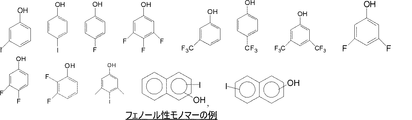
ポリマー主鎖中のフェノール性単位(A)の由来となるモノマーは構造(2)とすることができ、ここで、R1、R2およびR3は、前記のとおりである。 The monomer from which the phenolic unit (A) in the polymer main chain is derived can have the structure (2), wherein R 1 , R 2 and R 3 are as described above.
ポリマー主鎖中のフェノール性単位を形成するモノマー(2)のと規定の例は、図1に示すとおりである。 A specific example of the monomer (2) forming the phenolic unit in the polymer main chain is as shown in FIG.
本発明の新規ポリマーは、ここに示すヒドロキシ芳香族単位(A)およびアミノプラスト(B)を含む単位を含む。アミノプラストは、ポリマーを自己架橋もしくは他のポリマーと架橋させることができる。ある実施形態においては、新規ポリマーを含む組成物は自己架橋可能であり、他の架橋化合物を含まない。新規ポリマーは、アミノプラスト化合物と少なくとも一つのヨード部分またはフルオロ部分を含むヒドロキシ芳香族化合物と、トルエンスルホン酸などの強酸が触媒量存在する中で縮合重合した生成物である。アミノプラスト化合物は、反応性アミノメチレンアルコキシ部位(N−CH2−O−アルキル)を含む、そのいくつかは部分的に新規ポリマーを形成し、そして残りはポリマー中に存在し、膜の架橋を補助する。 The novel polymers of the present invention comprise units comprising the hydroxy aromatic units (A) and aminoplasts (B) shown here. Aminoplasts can crosslink polymers with other polymers or with other polymers. In some embodiments, the composition comprising the novel polymer is self-crosslinkable and free of other crosslinking compounds. The novel polymer is a product of condensation polymerization in the presence of a catalytic amount of an aminoplast compound, a hydroxyaromatic compound containing at least one iodo or fluoro moiety, and a strong acid such as toluenesulfonic acid. Aminoplast compounds contain reactive aminomethylene alkoxy moieties (N—CH 2 —O-alkyl), some of which form partly new polymers, and the rest are present in the polymer to crosslink the membrane. Assist.
新規ポリマーを得るための反応中に使用されるアミノプラスト化合物は、二つか三つ以上のアルコキシ基を含むことができ、そして、例えば、グリコールウリル−アルデヒド樹脂、メラミン−アルデヒド樹脂、ベンゾグアナミン−アルデヒド樹脂、および尿素−アルデヒド樹脂が挙げられる。アルデヒドの例として、ホルムアルデヒド、アセトアルデヒドなどが挙げられる。いくつかの場合において、3個または4個のアルコキシ基が有用である。例えば、モノマー性のアルキル化グリコールウリル−ホルムアルデヒド樹脂がある。一例として、以下の構造(3)を有するテトラ(アルコキシアルキル)グリコールウリルがある、 The aminoplast compound used in the reaction to obtain the new polymer can contain two or more alkoxy groups and includes, for example, glycoluril-aldehyde resins, melamine-aldehyde resins, benzoguanamine-aldehyde resins And urea-aldehyde resins. Examples of aldehydes include formaldehyde and acetaldehyde. In some cases, 3 or 4 alkoxy groups are useful. For example, monomeric alkylated glycoluril-formaldehyde resins. An example is tetra (alkoxyalkyl) glycoluril having the following structure (3):
ここで、各R6は、(CH2)n─O─(CH2)m─CH3であり、各R7およびR7’は、独立して、水素またはC1−C6アルキルであり、nは1〜4、そしてmは0〜3であり;(3)中のその数は化合物の命名のための原子の番号を示している。R6のいくつかの例としては、CH2OCH3、CH2OC2H5、およびCH2OC4H9である。アミノプラストの例は、CYMELの商標でCytec Industriesから商業的に入手できるものや、RESIMENEの商標でMonsanto Chemical Co.から商業的に入手できるものなどである。他のアミン類およびアミド類の縮合生成物も使用でき、例えばトリアジン類、ジアジン類、ジアゾール類、グアニジン類、グアニミン類、およびこれらの化合物のアルキル−およびアリール置換誘導体、例えばアルキル−およびアリール置換メラミン類のアルデヒド縮合物などがある。このような化合物の一部の例は、N,N’−ジメチル尿素、ベンゾユリア、ジシアンジアミド、ホルムアグアナミン、アセトグアナミン、アンメリン、2−クロロ−4,6−ジアミノ−1,3,5−トリアジン、6−メチル−2,4−ジアミノ,1,3,5−トライジン、3,5−ジアミノトリアゾール、トリアミノピリミジン、2−メルカプト−4,6−ジアミノ−ピリミジン、3,4,6−トリス(エチルアミノ)−1,3,5−トリアジン、トリス(アルコキシカルボニルアミノ)トリアジン、N,N,N’,N’−テトラメトキシメチルユリアおよび類似物などである。他の可能なアミノプラストには、図3、構造4−11に示す化合物などが挙げられる。追加的なアミノプラストのモノマーとしては、エーテル化されたアミノ樹脂、例えばメチル化もしくはブチル化メラミン樹脂(それぞれN−メトキシメチル−もしくはN−ブトキシメチル−メラミン)またはメチル化/ブチル化グリコールウリル類の類似物および誘導体が挙げられる。様々なメラミンおよび尿素樹脂が、Nicalacs(Sanwa Chemical Co.)、Plastopal(BASF AG)、またはMaprenal(Clariant GmbH)の商標で商業的に入手することができ、使用し得る。 Where each R 6 is (CH 2 ) n —O— (CH 2 ) m —CH 3 , and each R 7 and R 7 ′ is independently hydrogen or C 1 -C 6 alkyl. , N is 1-4, and m is 0-3; the number in (3) indicates the number of atoms for the nomenclature of the compound. Some examples of R 6 are CH 2 OCH 3 , CH 2 OC 2 H 5 and CH 2 OC 4 H 9 . Examples of aminoplasts are those commercially available from Cytec Industries under the CYMEL trademark, and Monsanto Chemical Co. under the RESIMENE trademark. Commercially available from Condensation products of other amines and amides can also be used, such as triazines, diazines, diazoles, guanidines, guanidines, and alkyl- and aryl-substituted derivatives of these compounds, such as alkyl- and aryl-substituted melamines Aldehyde condensates. Some examples of such compounds are N, N′-dimethylurea, benzourea, dicyandiamide, formaguanamine, acetoguanamine, ammelin, 2-chloro-4,6-diamino-1,3,5-triazine, 6 -Methyl-2,4-diamino, 1,3,5-triidine, 3,5-diaminotriazole, triaminopyrimidine, 2-mercapto-4,6-diamino-pyrimidine, 3,4,6-tris (ethylamino) ) -1,3,5-triazine, tris (alkoxycarbonylamino) triazine, N, N, N ′, N′-tetramethoxymethylurea and the like. Other possible aminoplasts include compounds shown in FIG. 3, structures 4-11, and the like. Additional aminoplast monomers include etherified amino resins such as methylated or butylated melamine resins (N-methoxymethyl- or N-butoxymethyl-melamine, respectively) or methylated / butylated glycolurils. Analogs and derivatives are mentioned. A variety of melamine and urea resins are commercially available and can be used under the trademarks Nicolas (Sanwa Chemical Co.), Plastopal (BASF AG), or Maprenal (Clariant GmbH).
より具体的には、アミノプラストは、構造(3)を有するグリコールウリル類からなる群から選択し得る。グリコールウリル類の例は、テトラ(アルコキシメチル)グリコールウリルであり、例えば、テトラ(メトキシメチル)グリコールウリル、テトラ(エトキシメチル)グリコールウリル、テトラ(n−プロポキシメチル)グリコールウリル、テトラ(i−プロポキシメチル)グリコールウリル、テトラ(n−ブトキシメチル)グリコールウリル、テトラ(t−ブトキシメチル)グリコールウリル、置換されたテトラ(アルコキシメチル)グリコールウリル類、例えば7−メチルテトラ(メトキシメチル)グリコールウリル、7−エチルテトラ(メトキシメチル)グリコールウリル、7−(i−もしくはn−)プロピルテトラ(メトキシメチル)グリコールウリル、7−(i−もしくはsec−もしくはt−)ブチルテトラ(メトキシメチル)グリコールウリル、7,8−ジメチルテトラ(メトキシメチル)グリコールウリル、7,8−ジエチルテトラ(メトキシメチル)グリコールウリル、7,8−ジ(i−もしくはn−)プロピルテトラ(メトキシメチル)グリコールウリル、7,8−ジ(i−もしくはsec−もしくはt−)ブチルテトラ(メトキシメチル)グリコールウリル、7−メチル−8−(i−もしくはn−)プロピルテトラ(メトキシメチル)グリコールウリル、および類似物などが挙げられ得る。テトラ(メトキシメチル)グリコールウリルは、Cytec IndustriesからPOWDERLINKの商標で入手できる(例えばPOWDERLINK1174)。他の例としては、メチルプロピルテトラメトキシメチルグリコールウリル、およびメチルフェニルテトラメトキシメチルグリコールウリルなどが挙げられる。図3は、具体的なアミノプラスト材料の例を挙げるものである。グリコールウリルのテトラメトキシメチルグリコールウリル、アミノプラストのより具体的な例である。 More specifically, the aminoplast may be selected from the group consisting of glycolurils having the structure (3). Examples of glycolurils are tetra (alkoxymethyl) glycoluril, for example, tetra (methoxymethyl) glycoluril, tetra (ethoxymethyl) glycoluril, tetra (n-propoxymethyl) glycoluril, tetra (i-propoxy). Methyl) glycoluril, tetra (n-butoxymethyl) glycoluril, tetra (t-butoxymethyl) glycoluril, substituted tetra (alkoxymethyl) glycolurils such as 7-methyltetra (methoxymethyl) glycoluril, 7 -Ethyltetra (methoxymethyl) glycoluril, 7- (i- or n-) propyltetra (methoxymethyl) glycoluril, 7- (i- or sec- or t-) butyltetra (methoxymethyl) Recalluril, 7,8-dimethyltetra (methoxymethyl) glycoluril, 7,8-diethyltetra (methoxymethyl) glycoluril, 7,8-di (i- or n-) propyltetra (methoxymethyl) glycoluril, 7,8-di (i- or sec- or t-) butyltetra (methoxymethyl) glycoluril, 7-methyl-8- (i- or n-) propyltetra (methoxymethyl) glycoluril, and the like May be mentioned. Tetra (methoxymethyl) glycoluril is available from Cytec Industries under the trademark POWDERLINK (eg POWDERLINK 1174). Other examples include methylpropyltetramethoxymethylglycoluril and methylphenyltetramethoxymethylglycoluril. FIG. 3 gives examples of specific aminoplast materials. More specific examples of glycoluril, tetramethoxymethylglycoluril and aminoplast.
新規ポリマーは、単位(A)、単位(B)、および付加的なモノマー性単位を含むことができる。付加的なモノマー性単位としては、他の単位と重合できればよい。モノマー単位の例としては、ナフチル、アントラシルおよびフェニルおよびその混合物を含むモノマーでよい。付加的な単位を形成するのに使用されるモノマーの具体例としては、フェノール、ナフトール、アントラセンメタノールおよびヒドロキシアントラセンである。 The novel polymer can comprise units (A), units (B), and additional monomeric units. Any additional monomeric unit may be used as long as it can be polymerized with other units. Examples of monomer units may be monomers including naphthyl, anthracyl and phenyl and mixtures thereof. Specific examples of monomers used to form additional units are phenol, naphthol, anthracene methanol and hydroxyanthracene.
(A)および(B)以外に、新規ポリマーは、フェノール性の構造(12)のようなコモノマー性単位(C)をさらに含む。構造12はフッ素原子若しくはヨウ素原子を含まないもしくはフリーのフェノール性化合物の任意の第二タイプの構造を示し、ここで、R1’、R2’、およびR3’は、独立して、H、ヒドロキシル、(C1−C4)アルキル、ヒドロキシ(C1−C4)アルキル、OC1−C4アルキル、(C=O)(C1−C4)アルキル、C1−C4アルキルO(C1−C4)アルキル、C1−C4アルキル(C=O)(C1−C4)アルキル、およびC(O)O(C1−C4)アルキルからなる群から選択する。 In addition to (A) and (B), the novel polymer further comprises comonomer units (C) such as the phenolic structure (12). Structure 12 represents any second type of structure of a phenolic compound that does not contain or are free of fluorine or iodine atoms, where R 1 ′ , R 2 ′ , and R 3 ′ are independently H , Hydroxyl, (C 1 -C 4 ) alkyl, hydroxy (C 1 -C 4 ) alkyl, OC 1 -C 4 alkyl, (C═O) (C 1 -C 4 ) alkyl, C 1 -C 4 alkyl O It is selected from the group consisting of (C 1 -C 4 ) alkyl, C 1 -C 4 alkyl (C═O) (C 1 -C 4 ) alkyl, and C (O) O (C 1 -C 4 ) alkyl.
使用することができる構造(12)のフェノールの具体的な例を、図4に示す。R1’、R2’、およびR3’の具体的な例としては、独立して、H、CH3、OH、C2H5、OCH3、C(O)−CH3、CH2OCH3、CH2C(O)−CH3である。 A specific example of a phenol of structure (12) that can be used is shown in FIG. Specific examples of R 1 ′ , R 2 ′ , and R 3 ′ are independently H, CH 3 , OH, C 2 H 5, OCH 3 , C (O) —CH 3, CH 2 OCH. 3, CH 2 C (O) —CH 3 .
新規ポリマーの幾つかの例を、図5〜7にさらに示す。 Some examples of novel polymers are further shown in FIGS.
本発明の新規組成物のポリマーは、溶剤存在中のモノマーおよび酸触媒を反応させることで合成できる。典型的には、ポリマーは水への沈殿で再生でき、その後、乾燥させる。このようなポリマーを製造する場合、ヨードもしくはフルオロフェノール(Aのモノマー)に対するアミノプラスト(Bのモノマー)のモル比は、3:1〜1:2または2:1〜1:1のモル比を採用できる。フルオロもしくはヨード不含の置換基を持たない任意の第二のフェノール性化合物を重合化に使用することができる。この第二のフェノール性化合物(Cのモノマー)は、フェノールを含有するフルオロもしくはヨードに対して0〜100モル%、または10〜80モル%、30〜60モル%の範囲で含むことができる。典型的には、低分子部分は分離される。反応、分離および精製の既知の技術を使用することができる。ポリマーの重量平均分子量は約1000〜約25000、又は約1500〜約15000の範囲とすることができる。 The polymer of the novel composition of the present invention can be synthesized by reacting a monomer and an acid catalyst in the presence of a solvent. Typically, the polymer can be regenerated by precipitation into water and then dried. In preparing such polymers, the molar ratio of aminoplast (B monomer) to iodo or fluorophenol (A monomer) is 3: 1 to 1: 2 or 2: 1 to 1: 1. Can be adopted. Any second phenolic compound that does not have a fluoro or iodo free substituent can be used in the polymerization. The second phenolic compound (monomer of C) can be included in the range of 0 to 100 mol%, or 10 to 80 mol%, and 30 to 60 mol% with respect to the fluoro- or iodo containing phenol . Typically, small molecule portions are separated. Known techniques of reaction, separation and purification can be used. The weight average molecular weight of the polymer can range from about 1000 to about 25000, or from about 1500 to about 15000.
新規ポリマーが193nmで吸収性を有しnおよびkの値の13.5nmの測定がいまだ洗練されていないため、ポリマーの屈折率、n(屈折率)およびk(吸収)は、193nmの露光波長で屈折率が約1.3から約2.0および吸収が約0.05から約1.0の範囲であってよい。ポリマー中または組成物中のヨードもしくはフルオロ含分は、固体ポリマーまたは組成物の元素分析により決定される。ポリマーのフルオロもしくはヨード含分は、ポリマーに対して質量%で1%〜65%または2%〜35%の範囲とすることができる。ポリマーのフルオロ含分は、ポリマーに対して質量%で1〜20%または5%〜15%の範囲とすることができる。ポリマーのヨード含分は、ポリマーに対して質量%で5%〜65%または10%〜35%の範囲とすることができる。EUV吸収は、ポリマー中の各原子の文献中の既知の原子吸収値に基づき、ポリマーの元素分析をベースとして、1.5/gより大きいか、1.5/gから20/g、または1.5/gから10/gの範囲と算出されえる。 Since the new polymer has an absorptivity at 193 nm and the measurement of n and k values of 13.5 nm is not yet refined, the refractive index of the polymer, n (refractive index) and k (absorption) is the exposure wavelength of 193 nm. The refractive index may range from about 1.3 to about 2.0 and the absorption may range from about 0.05 to about 1.0. The iodo or fluoro content in the polymer or composition is determined by elemental analysis of the solid polymer or composition. The fluoro or iodo content of the polymer can range from 1% to 65% or from 2% to 35% by weight with respect to the polymer. The fluoro content of the polymer can range from 1 to 20% or from 5% to 15% by weight with respect to the polymer. The iodine content of the polymer can range from 5% to 65% or from 10% to 35% by weight with respect to the polymer. EUV absorption is based on known atomic absorption values in the literature for each atom in the polymer and is based on the elemental analysis of the polymer, greater than 1.5 / g, 1.5 / g to 20 / g, or 1 It can be calculated as a range of 5 / g to 10 / g.
例えば、架橋を促進させるポリマー、膜のエッチング速度を増加させるポリマーなどの他のポリマーを組成物に加えることができる。もし組成物中に存在させるなら、これらの第二のポリマーはヨードもしくはフルオロ基が不含であり、全ポリマー組成物に対して10〜90%、または、15〜75%、または、20〜50%の範囲である。架橋に有効なポリマーは新規ポリマー中の基を架橋させることができる基を有するポリマーであり;そのようなポリマーの一つは二無水物と、少なくとも二つのヒドロキシ基を有する化合物または少なくとも二つのカルボン酸基または少なくとも一つのヒドロキシルおよび少なくとも一つのカルボン酸基を有する化合物との反応から形成されたポリエステルポリマーである。この様なポリマーは、引例として組み込まれる米国特許第7,638,262号、米国特許第7,264,913号、および2009年10月30日に出願の米国特許出願第12/609,222号に開示されている。新規組成物に添加剤として有用であり、新規組成物の膜のドライエッチング速度を増大させることができる他のポリマーとしては、引例として組み込まれる米国特許第7,691,556号および米国特許出願第2010/0009297号に開示されている。このようなポリマーの例としては、ジオール、グリコール、シアヌル酸化合と反応したグルコールウリル化合物である。これらの第二のポリマーはヨードもしくはフルオロ基が不含であり、アミノプラストを反応させて形成されたコポリマーであるえる。図8は、新規ポリマーに加え組成部に加えることができるポリマーの例を示すものである。 Other polymers can be added to the composition, for example, polymers that promote crosslinking, polymers that increase the etch rate of the film, and the like. If present in the composition, these second polymers are free of iodo or fluoro groups and are 10 to 90%, or 15 to 75%, or 20 to 50% of the total polymer composition. % Range. Crosslinkable polymers are polymers having groups capable of crosslinking groups in the new polymer; one such polymer is a dianhydride and a compound having at least two hydroxy groups or at least two carboxylic acids. A polyester polymer formed from reaction with an acid group or a compound having at least one hydroxyl and at least one carboxylic acid group. Such polymers are described in U.S. Patent No. 7,638,262, U.S. Patent No. 7,264,913, and U.S. Patent Application No. 12 / 609,222 filed October 30, 2009, which are incorporated by reference. Is disclosed. Other polymers that are useful as additives in the new compositions and that can increase the dry etch rate of the films of the new compositions include US Pat. No. 7,691,556 and US Patent Application No. 2010/0009297. Examples of such polymers are glycoluril compounds reacted with diols, glycols, cyanuric oxides. These second polymers are free of iodo or fluoro groups and can be copolymers formed by reacting aminoplasts. FIG. 8 shows examples of polymers that can be added to the composition in addition to the new polymer.
新規ポリマーを含有する本発明の新規の組成物にさらに架橋剤を含有することができる。典型的には、架橋剤は、求電子試薬として機能することができ、単独で、または酸の存在下でカルボカチオンを形成することができる化合物である。したがって、複数の求電子性部位を含有するアルコール、エーテル、エステル、オレフィン、メトキシメチルアミノ、メトキシメチルフェニルおよび他の分子などの基を含有する化合物は、ポリマーと架橋し得る。グリコールウリル、メラミンのポリマーなどのポリマー性架橋剤を使用してもよい。架橋剤であり得る化合物の例は、1,3アダマンタンジオール、1,3,5アダマンタントリオール、多官能性反応性ベンジル系化合物、構造(13)のテトラメトキシメチル−ビスフェノール(TMOM−BP)、アミノプラスト架橋剤、グリコールウリル、Cymels、Powderlinksなどである。 The novel composition of the present invention containing the novel polymer can further contain a crosslinking agent. Typically, the cross-linking agent is a compound that can function as an electrophile and can form a carbocation alone or in the presence of an acid. Thus, compounds containing groups such as alcohols, ethers, esters, olefins, methoxymethylamino, methoxymethylphenyl and other molecules containing multiple electrophilic moieties can crosslink with the polymer. Polymeric crosslinking agents such as glycoluril and melamine polymers may be used. Examples of compounds that can be crosslinkers include 1,3 adamantanediol, 1,3,5 adamantanetriol, polyfunctional reactive benzylic compounds, tetramethoxymethyl-bisphenol (TMOM-BP) of structure (13), amino Plast crosslinkers, glycoluril, Cymels, Powderlinks and the like.
ポリマーを含む新規な組成物はまた、酸発生剤および場合によって架橋剤も含んでよい。酸発生剤は、加熱すると強酸を生じさせ得る熱酸発生剤であってよい。本発明で使用される熱酸発生剤(TAG)は、本発明で存在するポリマーと反応し、ポリマーの架橋を伝播し得る酸を、加熱すると生じさせる任意の1種または複数であってよく、スルホン酸などの強酸が特に好ましい。好ましくは、熱酸発生剤は、90℃を超える温度で、より好ましくは120℃を超える温度で、さらにより好ましくは150℃を超える温度で活性化する。熱酸発生剤の例は、強非求核酸のトリアリールスルホニウム、ジアルキルアリールスルホニウムおよびジアリールアルキルスルホニウム塩、強非求核酸のアルキルアリールヨードニウム、ジアリールヨードニウム塩などの金属不含のスルホニウム塩およびヨードニウム塩;ならびに強非求核酸のアンモニウム、アルキルアンモニウム、ジアルキルアンモニウム、トリアルキルアンモニウム、テトラアルキルアンモニウム塩である。また、共有熱酸発生剤も、有用な添加剤として考えられ、例えばアルキルまたはアリールスルホン酸の2−ニトロベンジルエステルおよび熱分解して遊離スルホン酸をもたらすスルホン酸の他のエステルである。例は、ジアリールヨードニウムペルフルオロアルキルスルホネート、ジアリールヨードニウムトリス(フルオロアルキルスルホニル)メチド、ジアリールヨードニウムビス(フルオロアルキルスルホニル)メチド、ジアリールヨードニウムビス(フルオロアルキルスルホニル)イミド、ジアリールヨードニウム第4級アンモニウムペルフルオロアルキルスルホネートである。不安定なエステルの例:トシル酸2−ニトロベンジル、トシル酸2,4−ジニトロベンジル、トシル酸2,6−ジニトロベンジル、トシル酸4−ニトロベンジル;2−トリフルオロメチル−6−ニトロベンジル4−クロロベンゼンスルホネート、2−トリフルオロメチル−6−ニトロベンジル4−ニトロベンゼンスルホネートなどのベンゼンスルホネート;フェニル、4−メトキシベンゼンスルホネートなどのフェノール系スルホン酸エステル;第4級アンモニウムトリス(フルオロアルキルスルホニル)メチドおよび第4級アルキルアンモニウムビス(フルオロアルキルスルホニル)イミド、10−カンファースルホン酸のトリエチルアンモニウム塩などの有機酸のアルキルアンモニウム塩。様々な芳香族(アントラセン、ナフタレンまたはベンゼン誘導体)スルホン酸アミン塩をTAGとして用いることができ、米国特許第3,474,054号、同第4,200,729号、同第4,251,665号および同第5,187,019号に開示されたものが包含される。好ましくは、TAGは、170〜220℃の間の温度で非常に低い揮発性を有する。TAGの例は、NacureおよびCDXという名称でKing Industriesから販売されているものである。そのようなTAGは、Nacure 5225およびCDX−2168Eであり、これは、King Industries、Norwalk、Conn.06852、USAからプロピレングリコールメチルエーテル中25〜30%の活性で提供されるドデシルベンゼンスルホン酸アミン塩である。
The novel composition comprising the polymer may also comprise an acid generator and optionally a crosslinking agent. The acid generator may be a thermal acid generator that can generate a strong acid when heated. The thermal acid generator (TAG) used in the present invention may be any one or more that, upon heating, generates an acid that can react with the polymer present in the present invention and propagate the crosslinking of the polymer, Strong acids such as sulfonic acids are particularly preferred. Preferably, the thermal acid generator is activated at a temperature above 90 ° C, more preferably above 120 ° C, and even more preferably above 150 ° C. Examples of thermal acid generators include metal-free sulfonium and iodonium salts such as strongly non-nucleophilic triarylsulfonium, dialkylarylsulfonium and diarylalkylsulfonium salts, strongly non-nucleophilic alkylaryliodonium, diaryliodonium salts; And ammonium, alkylammonium, dialkylammonium, trialkylammonium and tetraalkylammonium salts of strongly non-nucleophilic nucleic acids. Covalent thermal acid generators are also considered as useful additives, such as 2-nitrobenzyl esters of alkyl or aryl sulfonic acids and other esters of sulfonic acids that are thermally decomposed to give free sulfonic acids. Examples are diaryl iodonium perfluoroalkyl sulfonate, diaryl iodonium tris (fluoroalkylsulfonyl) methide, diaryl iodonium bis (fluoroalkylsulfonyl) methide, diaryl iodonium bis (fluoroalkylsulfonyl) imide, diaryl iodonium quaternary ammonium perfluoroalkyl sulfonate. . Examples of labile esters: 2-nitrobenzyl tosylate, 2,4-dinitrobenzyl tosylate, 2,6-dinitrobenzyl tosylate, 4-nitrobenzyl tosylate; 2-trifluoromethyl-6-
新規な組成物はさらに、任意で少なくとも1種の公知の光酸発生剤をさらに含有していてもよく、その例は、限定ではないが、オニウム塩、スルホネート化合物、ニトロベンジルエステル、トリアジンなどである。好ましい光酸発生剤は、オニウム塩およびヒドロキシイミドのスルホン酸エステル、特に、ジフェニルヨードニウム塩、トリフェニルスルホニウム塩、ジアルキルヨードニウム塩、トリアルキルスルホニウム塩およびこれらの混合物である。これらの光酸発生剤は、必ずしも光分解するとは限らないが、熱分解して酸を形成する。新規組成物は光酸発生剤を不含とすることができる。 The novel composition may optionally further contain at least one known photoacid generator, examples of which include, but are not limited to, onium salts, sulfonate compounds, nitrobenzyl esters, triazines and the like. is there. Preferred photoacid generators are onium salts and sulfonic acid esters of hydroxyimide, in particular diphenyliodonium salts, triphenylsulfonium salts, dialkyliodonium salts, trialkylsulfonium salts and mixtures thereof. These photoacid generators are not necessarily photodegraded, but thermally decompose to form acids. The new composition can be free of photoacid generators.
本発明の反射防止コーティング組成物は、組成物中の全固形分に対して新規ポリマー10質量%から約100質量%、好ましくは40質量%から約80質量%を含有してよい。組成物中で使用する場合、任意の架橋剤は、全固形分に対して約0.2質量%から約10質量%で存在してよい。熱酸発生剤は、反射防止コーティング組成物の全固形分に対して約0から約5質量%、好ましくは固形分に対して0.3から2質量%の範囲で組み込むことができる。 The antireflective coating composition of the present invention may contain from 10% to about 100%, preferably from 40% to about 80%, by weight of the novel polymer, based on the total solids in the composition. When used in the composition, the optional crosslinker may be present from about 0.2% to about 10% by weight relative to the total solids. The thermal acid generator can be incorporated in the range of about 0 to about 5% by weight, preferably 0.3 to 2% by weight, based on the total solids of the antireflective coating composition.
一実施形態においては、新規組成物は、新規ポリマー、本明細書中に示した第二のポリマー、架橋剤、熱酸発生剤、任意に界面活性剤、および溶剤を含む。 In one embodiment, the new composition comprises a new polymer, a second polymer as set forth herein, a crosslinker, a thermal acid generator, optionally a surfactant, and a solvent.
一実施形態においては、新規組成物は、新規ポリマー、本明細書中に示した第二のポリマー、光酸発生剤、熱酸発生剤、任意に界面活性剤、および溶剤を含む。 In one embodiment, the novel composition comprises a novel polymer, a second polymer as set forth herein, a photoacid generator, a thermal acid generator, optionally a surfactant, and a solvent.
一実施形態においては、新規組成物は、熱および/または光酸発生剤を含まず、そして新規ポリマーは自己架橋可能である。 In one embodiment, the new composition does not include a heat and / or photoacid generator and the new polymer is self-crosslinkable.
コーティング組成物のための溶剤の例としては、アルコール、エステル、グリム、エーテル、グリコールエーテル、グリコールエーテルエステル、ケトン、ラクトン、環式ケトン、およびこれらの混合物が挙げられる。このような溶剤の例として、限定されないが、プロピレングリコールメチルエーテル(PGME)、プロピレングリコールメチルエーテルアセテート(PGMEA)、シクロヘキサノン、2−ヘプタノン、3−エトキシプロピオン酸エチル、乳酸エチル、ガンマバレロラクトン、3−メトキシプロピオン酸メチル、およびこれらの混合物が挙げられる。溶剤は、典型的には約40〜約99.9質量%の量で存在する。ある一定の場合において、ラクトン溶剤の添加は、積層系において用いられるとき、反射防止コーティング組成物の流動特性を促進するのに有用である。ラクトン溶剤は、存在する場合、溶剤系の約1〜約10%を占める。γ−バレロラクトンは、有用なラクトン溶剤の一つである。 Examples of solvents for the coating composition include alcohols, esters, glymes, ethers, glycol ethers, glycol ether esters, ketones, lactones, cyclic ketones, and mixtures thereof. Examples of such solvents include, but are not limited to, propylene glycol methyl ether (PGME), propylene glycol methyl ether acetate (PGMEA), cyclohexanone, 2-heptanone, ethyl 3-ethoxypropionate, ethyl lactate, gamma valerolactone, 3 -Methyl methoxypropionate, and mixtures thereof. The solvent is typically present in an amount of about 40 to about 99.9% by weight. In certain cases, the addition of a lactone solvent is useful to promote the flow characteristics of the antireflective coating composition when used in a laminated system. The lactone solvent, if present, accounts for about 1 to about 10% of the solvent system. γ-valerolactone is one useful lactone solvent.
反射防止被膜を基板の頂部にコーティングし、またドライ・エッチングに掛けるので、この被膜は、十分に低い金属イオン・レベルを有し、半導体デバイスの特性に悪影響を与えないような十分な純度を有することが企図される。イオン交換カラムにポリマー溶液を通過させるプロセス、濾過プロセスおよび抽出プロセスなどの処理を使用して、金属イオンの濃度を低下させ、粒子を減らすことができる。 Since the anti-reflective coating is coated on top of the substrate and subjected to dry etching, the coating has a sufficiently low metal ion level and sufficient purity so as not to adversely affect the characteristics of the semiconductor device. It is contemplated. Processes such as passing polymer solutions through ion exchange columns, filtration processes, and extraction processes can be used to reduce the concentration of metal ions and reduce particles.
新規な組成物の193nmにおける吸収パラメータ(k)は、偏光解析測定によると、露光波長で約0.05から約1.0、好ましくは約0.1から約0.8の範囲である。一実施形態では、組成物は、露光波長で約0.2から約0.5の範囲のk値を有する。反射防止コーティングの屈折率(n)もまた最適化され、約1.3から約2.0、好ましくは1.5から約1.8の範囲であり得る。ここに示されるnおよびkの値は、J.A.Woollam WVASE VU−32(商標)Ellipsometerなどの楕円偏光計を使用して算出することができる。kおよびnに関する最適な範囲の正確な値は、使用される露光波長および塗布の種類に左右される。前述のとおり、193mnの測定は、EUVパラメータの示唆するものとして使用する。 The absorption parameter (k) at 193 nm of the novel composition ranges from about 0.05 to about 1.0, preferably from about 0.1 to about 0.8 at the exposure wavelength, according to ellipsometric measurements. In one embodiment, the composition has a k value in the range of about 0.2 to about 0.5 at the exposure wavelength. The refractive index (n) of the antireflective coating is also optimized and can range from about 1.3 to about 2.0, preferably from 1.5 to about 1.8. The values of n and k shown here are A. It can be calculated using an ellipsometer, such as a Woollam WVASE VU-32 ™ Ellipsometer. The exact value of the optimal range for k and n depends on the exposure wavelength used and the type of coating. As mentioned above, the 193 mn measurement is used as an indication of EUV parameters.
反射防止コーティング組成物を、浸漬、スピン・コーティングまたは噴霧など、当業者によく知られている技術を使用して、基板上にコーティングする。EUVリソグラフィのための反射防止コーティングの被膜の厚さは、約5nmから約100nmの範囲であり、好ましくは5〜25nmである。コーティングをさらに、残留溶剤をすべて除去し、架橋を誘発するのに十分に長い時間、ホットプレート上でまたは対流式炉内で加熱して、反射防止コーティングを不溶化させて、反射防止コーティングとその上にコーティングされる層とが混合することを防ぐ。温度の好ましい範囲は、約120℃から約280℃である。 The antireflective coating composition is coated on the substrate using techniques well known to those skilled in the art, such as dipping, spin coating or spraying. The coating thickness of the antireflective coating for EUV lithography is in the range of about 5 nm to about 100 nm, preferably 5-25 nm. The coating is further heated on a hot plate or in a convection oven for a long enough time to remove any residual solvent and induce cross-linking to insolubilize the anti-reflective coating, thereby preventing the anti-reflective coating and above. Prevents mixing with the layer to be coated. A preferred range of temperature is from about 120 ° C to about 280 ° C.
フォトレジストの被膜を、新規反射防止下層コーティングの頂部にコーティングし、ベーク処理して、フォトレジスト溶剤を実質的に除去する。エッジビード・リムーバを、コーティング・ステップ後に施与して、当分野でよく知られているプロセスを使用して基板の縁部を清浄にすることができる。 A photoresist film is coated on top of the new antireflective underlayer coating and baked to substantially remove the photoresist solvent. An edge bead remover can be applied after the coating step to clean the edge of the substrate using processes well known in the art.
反射防止コーティングがその上に形成される基板は、半導体産業で典型的に使用される任意のものであってよい。適当な基板には、限定ではないが、低誘電率材料、シリコン、金属面でコーティングされたシリコン基板、銅がコーティングされたシリコン・ウェハ、銅、アルミニウム、ポリマー樹脂、二酸化シリコン、金属、ドーピングされた二酸化シリコン、窒化シリコン、タンタル、ポリシリコン、セラミックス、アルミニウム/銅混合物;ガリウムヒ素および他のそのような第III/V族化合物が包含される。基板は、上記の材料から作製された任意の数の層を含んでよい。 The substrate on which the anti-reflective coating is formed may be any that is typically used in the semiconductor industry. Suitable substrates include, but are not limited to, low dielectric constant materials, silicon, silicon substrates coated with metal surfaces, silicon wafers coated with copper, copper, aluminum, polymer resins, silicon dioxide, metals, doped Silicon dioxide, silicon nitride, tantalum, polysilicon, ceramics, aluminum / copper mixtures; gallium arsenide and other such Group III / V compounds are included. The substrate may include any number of layers made from the materials described above.
フォトレジストは、半導体産業で使用される任意の種類であってよいが、但し、フォトレジスト中の光活性化合物および反射防止コーティングが、イメージング・プロセスで使用される露光波長で実質的に吸収することを条件とする。 The photoresist may be of any type used in the semiconductor industry, provided that the photoactive compound and antireflective coating in the photoresist absorb substantially at the exposure wavelength used in the imaging process. As a condition.
今日までに、微細化に著しい進歩をもたらしたいくつかの主な深紫外線(uv)露光技術が存在し、これらの放射線は248nm、193nm、157および13.5nmである。248nmのためのフォトレジストは典型的には、米国特許第4,491,628号および米国特許第5,350,660号に記載されているものなど、置換ポリヒドロキシスチレンおよびそのコポリマー/オニウム塩をベースとしている。他方で、193nmおよび157nmで露光するためのフォトレジストは、芳香族がこの波長では不透明であるので、非芳香族ポリマーを必要とする。米国特許第5,843,624号および米国特許第6,866,984号は、193nm露光に有用なフォトレジストを開示している。一般に、脂環式炭化水素を含有するポリマーは、100〜200nmで露光するためのフォトレジストに使用される。脂環式炭化水素は、多くの理由でポリマーに組み込まれるが、それというのも主に、これらはエッチング耐性を改善する比較的高い炭素と水素との比を有し、低波長でも透明性をもたらし、比較的高いガラス転移温度を有するためである。米国特許第5,843,624号は、無水マレイン酸と不飽和環式モノマーとのフリーラジカル重合により得られるフォトレジストのためのポリマーを開示している。米国特許第6,447,980号および米国特許第6,723,488号に記載されていて、参照により本明細書に組み込まれるものなどの、任意の知られている種類の193nmフォトレジストを使用することができる。157nmに感光性があり、懸垂フルオロアルコール基を有するフッ素化ポリマーをベースとするフォトレジストの2つの基本的なクラスは、その波長で実質的に透明であることが知られている。一方のクラスの157nmフルオロアルコール・フォトレジストは、フッ素化ノルボルネンなどの基を含有するポリマーに由来し、金属触媒またはラジカル重合を使用してテトラフルオロエチレンなどの他の透明なモノマーとホモ重合または共重合される(米国特許第6,790,587号および米国特許第6,849,377号)。一般に、これらの材料はより高い吸光度をもたらすが、それらの高い脂環式含分により、良好なプラズマ・エッチング耐性を有する。さらに最近では、ポリマー主鎖が、1,1,2,3,3−ペンタフルオロ−4−トリフルオロメチル−4−ヒドロキシ−1,6−ヘプタジエンなどの不斉ジエンの環化重合(米国特許第6,818,258号)またはフルオロジエンとオレフィンとの共重合(米国特許第6,916,590号)に由来する157nmフルオロアルコール・ポリマーの群が記載された。これらの材料は、157nmで許容可能な吸光度をもたらすが、フルオロ−ノルボルネン・ポリマーに比べてその脂環式含分が低いので、より低いプラズマ・エッチング耐性を有する。これら2つの群のポリマーは、第1の種類のポリマーの高いエッチング耐性と第2の種類のポリマーの157nmでの高い透明性とのバランスをもたらすために、ブレンドし得ることが多い。 To date, there are several major deep ultraviolet (uv) exposure technologies that have made significant progress in miniaturization, and these radiations are 248 nm, 193 nm, 157 and 13.5 nm. Photoresists for 248 nm typically contain substituted polyhydroxystyrene and its copolymers / onium salts, such as those described in US Pat. No. 4,491,628 and US Pat. No. 5,350,660. Based on. On the other hand, photoresists for exposure at 193 nm and 157 nm require non-aromatic polymers since aromatics are opaque at this wavelength. US Pat. No. 5,843,624 and US Pat. No. 6,866,984 disclose photoresists useful for 193 nm exposure. In general, polymers containing alicyclic hydrocarbons are used in photoresists for exposure at 100-200 nm. Cycloaliphatic hydrocarbons are incorporated into polymers for a number of reasons, primarily because they have a relatively high carbon to hydrogen ratio that improves etch resistance and are transparent at low wavelengths. Because it has a relatively high glass transition temperature. US Pat. No. 5,843,624 discloses polymers for photoresists obtained by free radical polymerization of maleic anhydride and unsaturated cyclic monomers. Use any known type of 193 nm photoresist, such as those described in US Pat. No. 6,447,980 and US Pat. No. 6,723,488, which are incorporated herein by reference. can do. Two basic classes of photoresists that are sensitive to 157 nm and are based on fluorinated polymers with pendant fluoroalcohol groups are known to be substantially transparent at that wavelength. One class of 157 nm fluoroalcohol photoresists is derived from polymers containing groups such as fluorinated norbornene and is homopolymerized or co-polymerized with other transparent monomers such as tetrafluoroethylene using metal catalysts or radical polymerization. Polymerized (US Pat. No. 6,790,587 and US Pat. No. 6,849,377). In general, these materials provide higher absorbance but have good plasma etch resistance due to their high alicyclic content. More recently, the polymer backbone has undergone cyclopolymerization of asymmetric dienes such as 1,1,2,3,3-pentafluoro-4-trifluoromethyl-4-hydroxy-1,6-heptadiene (US Pat. 6,818,258) or a group of 157 nm fluoroalcohol polymers derived from copolymerization of fluorodienes and olefins (US Pat. No. 6,916,590) have been described. These materials provide acceptable absorbance at 157 nm, but have lower plasma etch resistance due to their lower alicyclic content compared to fluoro-norbornene polymers. These two groups of polymers can often be blended to provide a balance between the high etch resistance of the first type of polymer and the high transparency at 157 nm of the second type of polymer.
13.5nmの極紫外線(EUV)を吸収するフォトレジストが特に有用であり、当分野で知られている。このようなEUVフォトレジストは現在開発中であり、しかしあらゆる安定なEUVフォトレジストを使用することができる。新規なコーティングはまた、電子線リソグラフィで使用することもでき、露光は電子線を使用して行う。 Photoresists that absorb extreme ultraviolet radiation (EUV) at 13.5 nm are particularly useful and are known in the art. Such EUV photoresists are currently under development, but any stable EUV photoresist can be used. The novel coating can also be used in electron beam lithography, and exposure is performed using an electron beam.
新規組成物の膜を形成するためのコーティング・プロセスの後に、フォトレジストをマスクもしくは電子線ともに像様露光する。露光は、典型的な露光装置を使用して行ってもよい。露光の波長源は、如何なるものも使用できるが、13.5nmである。次いで、露光されたフォトレジストを、水性現像液で現像して、処理されたフォトレジストを除去する。現像液は好ましくは、例えば水酸化テトラメチルアンモニウム(TMAH)を含むアルカリ水溶液である。現像液の例としては、0.26Nの水性水酸化テトラメチルアンモニウム(TMAH)溶液である。現像は60秒とすることができる。現像液はさらに、界面活性剤(複数可)を含んでもよい。任意選択の加熱ステップを、現像前および露光後のプロセスに組み込むことができる。現像により、現像段階で除去されていない新規下層膜上にフォトレジストパターンが形成される。 After the coating process to form a film of the new composition, the photoresist is imagewise exposed with a mask or electron beam. The exposure may be performed using a typical exposure apparatus. Any wavelength source for exposure can be used, but it is 13.5 nm. The exposed photoresist is then developed with an aqueous developer to remove the processed photoresist. The developer is preferably an alkaline aqueous solution containing, for example, tetramethylammonium hydroxide (TMAH). An example of a developer is a 0.26N aqueous tetramethylammonium hydroxide (TMAH) solution. Development can be for 60 seconds. The developer may further contain a surfactant (s). An optional heating step can be incorporated into the pre-development and post-exposure processes. By development, a photoresist pattern is formed on the new lower layer film that has not been removed in the development stage.
フォトレジストをコーティングおよびイメージングするプロセスは、当業者によく知られており、使用されるフォトレジストの特定の種類のために最適化される。次いで、パターニングされた基板を、適当なエッチング・チャンバ内でエッチング・ガスまたはガスの混合物でドライ・エッチングして、反射防止被膜または多数の層の反射防止コーティングの露光部分を除去することができるが、この際、残存しているフォトレジストがエッチング・マスクとして機能する。O2、CF4、CHF3、Cl2、HBr、SO2、COなどを含むものなど、様々なエッチング・ガスが、有機反射防止コーティングをエッチングするために当分野では知られている。 The process of coating and imaging the photoresist is well known to those skilled in the art and is optimized for the particular type of photoresist used. The patterned substrate can then be dry etched with an etching gas or mixture of gases in a suitable etching chamber to remove the exposed portions of the antireflective coating or multiple layers of antireflective coatings. At this time, the remaining photoresist functions as an etching mask. Various etching gases are known in the art for etching organic anti-reflective coatings, such as those including O 2 , CF 4 , CHF 3 , Cl 2 , HBr, SO 2 , CO, and the like.
上記で参照された文献はそれぞれ、その全体が、あらゆる目的で、参照により本明細書に組み込まれる。下記の具体的な例では、本発明の組成物を生成および利用する方法の詳細な説明を提供する。しかしながら、これらの例は、本発明の範囲を限定または制限することを何ら意図したものではなく、本発明を実施するために専ら利用しなければならない条件、パラメータまたは値を提供していると解釈すべきではない。 Each of the documents referred to above is hereby incorporated by reference in its entirety for all purposes. The specific examples below provide a detailed description of how to make and utilize the compositions of the present invention. However, these examples are not intended to limit or limit the scope of the invention in any way, and are interpreted as providing conditions, parameters or values that must be used exclusively to practice the invention. should not do.
下記の例における炭素ハードマスク反射防止コーティングの屈折率(n)および吸収度(k)の値は、J.A.Woollam VASE32楕円偏光計で測定した。 The values of the refractive index (n) and the absorbance (k) of the carbon hard mask antireflection coating in the following examples are as follows. A. Measured with a Woollam VASE32 ellipsometer.
ポリマーの分子量を、ゲル浸透クロマトグラフで測定した。 The molecular weight of the polymer was measured by gel permeation chromatography.
例1
30gのテトラメトキシメチルグルコールウリル、5.3gの4−フルオロフェノール,30mlのテトラヒドロフラン(THF)および40mlのプロピレングリコールメチルエーテルアセテート(PGMEA)を温度計、機械的攪拌機および冷水凝縮器を備えたフラスコ中に仕込んだ。触媒量のパラ−トルエンスルホン酸一水和物(0.35g)を添加後、反応物を80℃で約4時間保持した。その後、反応溶液を室温まで冷却し、そして濾過した。攪拌しながらポリマーが沈殿させつつ、濾液を蒸留水にゆっくり注いだ。ポリマーを濾過により集めた。乾燥後、ポリマーをTHF中に再溶解し、そして水中に沈殿させた。ポリマーを濾過し、水を通して洗浄し低圧オーブンで乾燥させた。重量平均分子量約8100g/molの13.2gのポリマー生成物を得た。元素分析によるとフッ素含有量はポリマー中2.0%であった。
Example 1
A flask equipped with 30 g tetramethoxymethylglycoluril, 5.3 g 4-fluorophenol, 30 ml tetrahydrofuran (THF) and 40 ml propylene glycol methyl ether acetate (PGMEA) with thermometer, mechanical stirrer and cold water condenser Prepared inside. After adding a catalytic amount of para-toluenesulfonic acid monohydrate (0.35 g), the reaction was held at 80 ° C. for about 4 hours. The reaction solution was then cooled to room temperature and filtered. The filtrate was slowly poured into distilled water as the polymer precipitated while stirring. The polymer was collected by filtration. After drying, the polymer was redissolved in THF and precipitated into water. The polymer was filtered, washed through water and dried in a low pressure oven. 13.2 g of polymer product with a weight average molecular weight of about 8100 g / mol was obtained. According to elemental analysis, the fluorine content was 2.0% in the polymer.
例2
30gのテトラメトキシメチルグルコールウリル、10.4gの4−ヨードフェノール、40mlのTHFおよび40mlのPGMEAを温度計、機械的攪拌機および冷水凝縮器を備えたフラスコ中に仕込んだ。触媒量のパラ−トルエンスルホン酸一水和物(0.35g)を添加後、反応物を80℃で約7時間保持した。その後、反応溶液を室温まで冷却し、そして濾過した。攪拌しながらポリマーが沈殿させつつ、濾液を蒸留水にゆっくり注いだ。ポリマーを濾過により集めた。乾燥後、ポリマーをTHF中に再溶解し、そして水中に沈殿させた。ポリマーを濾過し、水を通して洗浄し低圧オーブンで乾燥させた。重量平均分子量約2200g/molの18.0gのポリマー生成物を得た。元素分析によるとヨウ素含有量はポリマー中21.1%であった。
Example 2
30 g tetramethoxymethylglycoluril, 10.4 g 4-iodophenol, 40 ml THF and 40 ml PGMEA were charged into a flask equipped with a thermometer, mechanical stirrer and cold water condenser. After adding a catalytic amount of para-toluenesulfonic acid monohydrate (0.35 g), the reaction was held at 80 ° C. for about 7 hours. The reaction solution was then cooled to room temperature and filtered. The filtrate was slowly poured into distilled water as the polymer precipitated while stirring. The polymer was collected by filtration. After drying, the polymer was redissolved in THF and precipitated into water. The polymer was filtered, washed through water and dried in a low pressure oven. 18.0 g of polymer product with a weight average molecular weight of about 2200 g / mol was obtained. According to elemental analysis, the iodine content was 21.1% in the polymer.
例3
30gのテトラメトキシメチルグルコールウリル、10.4gの3−ヨードフェノール、40mlのTHFおよび40mlのPGMEAを温度計、機械的攪拌機および冷水凝縮器を備えたフラスコ中に仕込んだ。触媒量のパラ−トルエンスルホン酸一水和物(0.3g)を添加後、反応物を80℃で約7時間保持した。の後、反応溶液を室温まで冷却し、そして濾過した。攪拌しながらポリマーが沈殿させつつ、濾液を蒸留水にゆっくり注いだ。ポリマーを濾過により集めた。乾燥後、ポリマーをTHF中に再溶解し、そして水中に沈殿させた。ポリマーを濾過し、水を通して洗浄し低圧オーブンで乾燥させた。重量平均分子量約3500g/molの24.0gのポリマー生成物を得た。元素分析によるとヨウ素含有量はポリマー中21.7%であった。EUV吸収は、ポリマー中の各原子の文献中の既知の原子吸収値に基づき、ポリマーの元素分析をベースとして、7.7/gと算出された。
Example 3
30 g tetramethoxymethylglycoluril, 10.4 g 3-iodophenol, 40 ml THF and 40 ml PGMEA were charged into a flask equipped with a thermometer, mechanical stirrer and cold water condenser. After adding a catalytic amount of para-toluenesulfonic acid monohydrate (0.3 g), the reaction was held at 80 ° C. for about 7 hours. After that, the reaction solution was cooled to room temperature and filtered. The filtrate was slowly poured into distilled water as the polymer precipitated while stirring. The polymer was collected by filtration. After drying, the polymer was redissolved in THF and precipitated into water. The polymer was filtered, washed through water and dried in a low pressure oven. 24.0 g of polymer product with a weight average molecular weight of about 3500 g / mol was obtained. According to elemental analysis, the iodine content was 21.7% in the polymer. The EUV absorption was calculated as 7.7 / g based on the elemental analysis of the polymer based on the known atomic absorption values in the literature for each atom in the polymer.
例4
20gのテトラメトキシメチルグルコールウリル、6.9gの3−ヨードフェノール、2.9gの3,4,5−トリメトキシフェノール、30mlのTHFおよび30mlのPGMEAを温度計、機械的攪拌機および冷水凝縮器を備えたフラスコ中に仕込んだ。触媒量のパラ−トルエンスルホン酸一水和物(0.2g)を添加後、反応物を80℃で約5.5時間保持した。反応溶液を室温まで冷却し、そして濾過した。攪拌しながらポリマーが沈殿させつつ、濾液を蒸留水にゆっくり注いだ。ポリマーを濾過により集めた。乾燥後、ポリマーをTHF中に再溶解し、そして水中に沈殿させた。ポリマーを濾過し、水を通して洗浄し低圧オーブンで乾燥させた。重量平均分子量約2400g/molの18.0gのポリマー生成物を得た。
Example 4
20 g tetramethoxymethylglycoluril, 6.9 g 3-iodophenol, 2.9
例5
30gのテトラメトキシメチルグルコールウリル、8.2gの3,5−ジフルオロフェノール、40mlのTHFおよび40mlのPGMEAを温度計、機械的攪拌機および冷水凝縮器を備えたフラスコ中に仕込んだ。触媒量のパラ−トルエンスルホン酸一水和物(0.3g)を添加後、反応物を80℃で約8時間保持した。反応溶液を室温まで冷却し、そして濾過した。攪拌しながらポリマーが沈殿させつつ、濾液を蒸留水にゆっくり注いだ。ポリマーを濾過により集めた。乾燥後、ポリマーをTHF中に再溶解し、そして水中に沈殿させた。ポリマーを濾過し、水を通して洗浄し低圧オーブンで乾燥させた。重量平均分子量約6200g/molの18.0gのポリマー生成物を得た。元素分析によるとフッ素含有量はポリマー中7.1%であった。EUV吸収は、ポリマー中の各原子の文献中の既知の原子吸収値に基づき、ポリマーの元素分析をベースとして、1.57/gと算出された。
Example 5
30 g tetramethoxymethylglycoluril, 8.2 g 3,5-difluorophenol, 40 ml THF and 40 ml PGMEA were charged into a flask equipped with a thermometer, mechanical stirrer and cold water condenser. After adding a catalytic amount of para-toluenesulfonic acid monohydrate (0.3 g), the reaction was held at 80 ° C. for about 8 hours. The reaction solution was cooled to room temperature and filtered. The filtrate was slowly poured into distilled water as the polymer precipitated while stirring. The polymer was collected by filtration. After drying, the polymer was redissolved in THF and precipitated into water. The polymer was filtered, washed through water and dried in a low pressure oven. 18.0 g of polymer product with a weight average molecular weight of about 6200 g / mol was obtained. According to elemental analysis, the fluorine content was 7.1% in the polymer. The EUV absorption was calculated to be 1.57 / g based on the elemental analysis of the polymer based on the known atomic absorption values in the literature for each atom in the polymer.
例6
30gのテトラメトキシメチルグルコールウリル、7.6gの4−トリフルオロメチルフェノール、30mlのTHFおよび50mlのPGMEAを温度計、機械的攪拌機および冷水凝縮器を備えたフラスコ中に仕込んだ。触媒量のパラ−トルエンスルホン酸一水和物(0.3g)を添加後、反応物を80℃で約7時間保持した。反応溶液を室温まで冷却し、そして濾過した。攪拌しながらポリマーが沈殿させつつ、濾液を蒸留水にゆっくり注いだ。ポリマーを濾過により集めた。乾燥後、ポリマーをTHF中に再溶解し、そして水中に沈殿させた。ポリマーを濾過し、水を通して洗浄し低圧オーブンで乾燥させた。重量平均分子量約14500g/molの17.0gのポリマー生成物を得た。元素分析によるとフッ素含有量はポリマー中5.3%であった。
Example 6
30 g tetramethoxymethylglycoluril, 7.6 g 4-trifluoromethylphenol, 30 ml THF and 50 ml PGMEA were charged into a flask equipped with a thermometer, mechanical stirrer and cold water condenser. After adding a catalytic amount of para-toluenesulfonic acid monohydrate (0.3 g), the reaction was held at 80 ° C. for about 7 hours. The reaction solution was cooled to room temperature and filtered. The filtrate was slowly poured into distilled water as the polymer precipitated while stirring. The polymer was collected by filtration. After drying, the polymer was redissolved in THF and precipitated into water. The polymer was filtered, washed through water and dried in a low pressure oven. A 17.0 g polymer product with a weight average molecular weight of about 14500 g / mol was obtained. According to elemental analysis, the fluorine content was 5.3% in the polymer.
例7
20gのテトラメトキシメチルグルコールウリル、6.9gの3−ヨードフェノール、2.0gの2,5−ジメチルフェノール、30mlのTHFおよび30mlのPGMEAを温度計、機械的攪拌機および冷水凝縮器を備えたフラスコ中に仕込んだ。触媒量のパラ−トルエンスルホン酸一水和物(0.2g)を添加後、反応物を80℃で約4.5時間保持した。反応溶液を室温まで冷却し、そして濾過した。攪拌しながらポリマーが沈殿させつつ、濾液を蒸留水にゆっくり注いだ。ポリマーを濾過により集めた。乾燥後、ポリマーをTHF中に再溶解し、そして水中に沈殿させた。ポリマーを濾過し、水を通して洗浄し低圧オーブンで乾燥させた。重量平均分子量約5100g/molの17.7gのポリマー生成物を得た。EUV吸収は、ポリマー中の各原子の文献中の既知の原子吸収値に基づき、ポリマーの元素分析をベースとして、7.0/gと算出された。
Example 7
20 g tetramethoxymethylglycoluril, 6.9 g 3-iodophenol, 2.0
例8
30gのテトラメトキシメチルグルコールウリル、10.8gの3,5−bis(トリフルオロメチル)フェノール、2.9gの2,5−ジメチルフェノール、30mlのTHFおよび50mlのPGMEAを温度計、機械的攪拌機および冷水凝縮器を備えたフラスコ中に仕込んだ。触媒量のパラ−トルエンスルホン酸一水和物(0.25g)を添加後、反応物を80℃で約4.5時間保持した。反応溶液を室温まで冷却し、そして濾過した。攪拌しながらポリマーが沈殿させつつ、濾液を蒸留水にゆっくり注いだ。ポリマーを濾過により集めた。乾燥後、ポリマーをTHF中に再溶解し、そして水中に沈殿させた。ポリマーを濾過し、水を通して洗浄し低圧オーブンで乾燥させた。重量平均分子量約10000g/molの21.0gのポリマー生成物を得た。元素分析によるとフッ素含有量はポリマー中12.5%であった。
Example 8
30 g of tetramethoxymethyl glycoluril, 10.8 g of 3,5-bis (trifluoromethyl) phenol, 2.9 g of 2,5-dimethylphenol, 30 ml of THF and 50 ml of PGMEA were thermometer, mechanical stirrer And charged into a flask equipped with a cold water condenser. After adding a catalytic amount of para-toluenesulfonic acid monohydrate (0.25 g), the reaction was held at 80 ° C. for about 4.5 hours. The reaction solution was cooled to room temperature and filtered. The filtrate was slowly poured into distilled water as the polymer precipitated while stirring. The polymer was collected by filtration. After drying, the polymer was redissolved in THF and precipitated into water. The polymer was filtered, washed through water and dried in a low pressure oven. 21.0 g of polymer product with a weight average molecular weight of about 10,000 g / mol was obtained. According to elemental analysis, the fluorine content was 12.5% in the polymer.
例9
30gのテトラメトキシメチルグルコールウリル、10.4gの3−ヨードフェノール、3.7gの4−アセチルレゾルシノール、40mlのTHFおよび40mlのPGMEAを温度計、機械的攪拌機および冷水凝縮器を備えたフラスコ中に仕込んだ。触媒量のパラ−トルエンスルホン酸一水和物(0.3g)を添加後、反応物を80℃で約6時間保持した。反応溶液を室温まで冷却し、そして濾過した。攪拌しながらポリマーが沈殿させつつ、濾液を蒸留水にゆっくり注いだ。ポリマーを濾過により集めた。乾燥後、ポリマーをTHF中に再溶解し、そして水中に沈殿させた。ポリマーを濾過し、水を通して洗浄し低圧オーブンで乾燥させた。重量平均分子量約3900g/molの26.0gのポリマー生成物を得た。
Example 9
30 g tetramethoxymethylglycoluril, 10.4 g 3-iodophenol, 3.7 g 4-acetylresorcinol, 40 ml THF and 40 ml PGMEA in a flask equipped with a thermometer, mechanical stirrer and cold water condenser Was charged. After adding a catalytic amount of para-toluenesulfonic acid monohydrate (0.3 g), the reaction was held at 80 ° C. for about 6 hours. The reaction solution was cooled to room temperature and filtered. The filtrate was slowly poured into distilled water as the polymer precipitated while stirring. The polymer was collected by filtration. After drying, the polymer was redissolved in THF and precipitated into water. The polymer was filtered, washed through water and dried in a low pressure oven. 26.0 g of polymer product with a weight average molecular weight of about 3900 g / mol was obtained.
例10
20gのテトラメトキシメチルグルコールウリル、6.0gの3−ヨードフェノール、4.9gの3,5−ジメチル4−ヨードフェノール、30mlのTHFおよび30mlのPGMEAを温度計、機械的攪拌機および冷水凝縮器を備えたフラスコ中に仕込んだ。触媒量のパラ−トルエンスルホン酸一水和物(0.2g)を添加後、反応物を80℃で約5時間保持した。反応溶液を室温まで冷却し、そして濾過した。攪拌しながらポリマーが沈殿させつつ、濾液を蒸留水にゆっくり注いだ。ポリマーを濾過により集めた。乾燥後、ポリマーをTHF中に再溶解し、そして水中に沈殿させた。ポリマーを濾過し、水を通して洗浄し低圧オーブンで乾燥させた。重量平均分子量約3800g/molの21.0gのポリマー生成物を得た。
Example 10
20 g tetramethoxymethylglycoluril, 6.0 g 3-iodophenol, 4.9 g 3,5-dimethyl 4-iodophenol, 30 ml THF and 30 ml PGMEA thermometer, mechanical stirrer and cold water condenser In a flask equipped with After the addition of a catalytic amount of para-toluenesulfonic acid monohydrate (0.2 g), the reaction was held at 80 ° C. for about 5 hours. The reaction solution was cooled to room temperature and filtered. The filtrate was slowly poured into distilled water as the polymer precipitated while stirring. The polymer was collected by filtration. After drying, the polymer was redissolved in THF and precipitated into water. The polymer was filtered, washed through water and dried in a low pressure oven. 21.0 g of polymer product with a weight average molecular weight of about 3800 g / mol was obtained.
例11
10gのブタンテトラカルボン酸二無水物、7gのスチレングリコール、0.5gのベンジルトリブチル塩化アンモニウム、および35gのプロピレングリコールメチルエーテルアセテート(PGMEA)を凝縮器、熱コントローラおよび機械的攪拌機を備えたフラスコ中に仕込んだ。窒素雰囲気下、攪拌しながら、混合物を110℃に加熱した。1〜2時間後に透明な溶液が得られた。温度を110℃で3時間保持した。冷却後、60gのPGMEAおよび36gの酸化プロピレンを上記溶液と混合した。反応物を50℃で48時間保持した。反応溶液を室温まで冷却し高速ブレンダー中で大量の水にゆっくり注いだ。ポリマーを集め、水を通して洗浄した。最後に、ポリマーを低圧オーブンで乾燥させた。重量平均分子量(MW)約20000g/molの16gのポリマー生成物を得た。
Example 11
10 g butanetetracarboxylic dianhydride, 7 g styrene glycol, 0.5 g benzyltributylammonium chloride, and 35 g propylene glycol methyl ether acetate (PGMEA) in a flask equipped with a condenser, thermal controller and mechanical stirrer Was charged. The mixture was heated to 110 ° C. with stirring under a nitrogen atmosphere. A clear solution was obtained after 1-2 hours. The temperature was held at 110 ° C. for 3 hours. After cooling, 60 g PGMEA and 36 g propylene oxide were mixed with the above solution. The reaction was held at 50 ° C. for 48 hours. The reaction solution was cooled to room temperature and slowly poured into a large amount of water in a high-speed blender. The polymer was collected and washed through water. Finally, the polymer was dried in a low pressure oven. 16 g of polymer product having a weight average molecular weight (MW) of about 20000 g / mol was obtained.
例12
110gのテトラメトキシメチルグルコールウリルおよび61gのトリス(2−ヒドロキシエチル)シアヌル酸を350gのジオキサン中に添加した。温度を92〜94℃に上昇させ、透明な溶液が得られた。0.7gのパラトルエンスルホン酸(PTSA)を添加し、反応物を6時間還流させた。室温まで冷却後、0.5gのトリエチルアミンを添加した。溶液をn−ブチルアセタートを5℃で沈殿させた。ポリマーを濾過し、減圧下乾燥させた。得られたポリマーは約2200g/molの重量平均分子量を有していた。
Example 12
110 g tetramethoxymethylglycoluril and 61 g tris (2-hydroxyethyl) cyanuric acid were added to 350 g dioxane. The temperature was raised to 92-94 ° C. and a clear solution was obtained. 0.7 g of paratoluenesulfonic acid (PTSA) was added and the reaction was refluxed for 6 hours. After cooling to room temperature, 0.5 g of triethylamine was added. The solution was precipitated with n-butyl acetate at 5 ° C. The polymer was filtered and dried under reduced pressure. The resulting polymer had a weight average molecular weight of about 2200 g / mol.
例13
合成例1〜9のポリマーから得られた下層膜のための溶液および現像液に対する耐性の評価
PGMEA/PGME70/30中に合成例1からのポリマー溶液を作成した。溶液をケイ素ウェハ上にスピンコートし、200℃/60sベーク処理し膜を形成した。PGMEA/PGME70/30溶剤を、合成例1のポリマー溶液からの下層材料でコーティングしたケイ素ウェハ上に60sで施した。窒素を吹き込んで溶剤を除去した。有意なフィルムの損失は観察されなかった。同様の実験を現像剤としてAZ(登録商標)300MIF Developerを用いて行った。上記のEUV下層膜は、現像剤に対して良好な耐性を示した。
Example 13
Evaluation of Resistance to Solutions and Developers for Underlayer Films Obtained from Polymers of Synthesis Examples 1-9 Polymer solutions from Synthesis Example 1 were made in PGMEA / PGME 70/30. The solution was spin-coated on a silicon wafer and baked at 200 ° C./60 s to form a film. PGMEA / PGME 70/30 solvent was applied in 60 s on a silicon wafer coated with the underlayer material from the polymer solution of Synthesis Example 1. Nitrogen was blown to remove the solvent. No significant film loss was observed. A similar experiment was conducted using AZ® 300MIF Developer as the developer. The above EUV underlayer film showed good resistance to the developer.
上記の実験を、PGMEA/PGME70/30中で、合成例2〜9からのポリマーで製造されたポリマー溶液で繰り返した。上記のEUV下層膜は、キャスト溶剤および現像剤の両方に対して良好な耐性を示した。溶剤処理および現像液処理ののち、フィルムの損失は観察されなかった。 The above experiment was repeated in PGMEA / PGME 70/30 with polymer solutions made with the polymers from Synthesis Examples 2-9. The above EUV underlayer film showed good resistance to both cast solvent and developer. No film loss was observed after solvent treatment and developer treatment.
例14
1.71gの合成例12からのポリマー、0.73gの合成例11からの生成物および0.49gの合成例2からの生成物を、287gのPGMEA/PGME70/30溶剤および8.9gガンマ−バレロラクトンに溶解し、1.0質量%溶液を作成した。混合物を0.2μMのサイズの孔のマイクロフィルタで濾過した。溶液を同じ溶剤により希薄し所望の膜厚とし、その後40秒間ケイ素ウェハ上にスピンコートした。その後、コーティングされたウェハをホットプレート上で1分間200℃で加熱した。
Example 14
1.71 g of the polymer from Synthesis Example 12, 0.73 g of the product from Synthesis Example 11 and 0.49 g of the product from Synthesis Example 2 were mixed with 287 g of PGMEA / PGME 70/30 solvent and 8.9 g of gamma − Dissolved in valerolactone to prepare a 1.0 mass% solution. The mixture was filtered through a microfilter with a pore size of 0.2 μM. The solution was diluted with the same solvent to the desired film thickness and then spin coated on a silicon wafer for 40 seconds. The coated wafer was then heated on a hot plate for 1 minute at 200 ° C.
例15
0.6gの合成例11からの生成物および1.4gの合成例5からの生成物を、192gのPGMEA/PGME70/30溶剤および5.9gガンマ−バレロラクトンに溶解し、1.0質量%溶液を作成した。混合物を0.2μMのサイズの孔のマイクロフィルタで濾過した。溶液を同じ溶剤により希薄し所望の膜厚とし、その後40秒間ケイ素ウェハ上にスピンコートした。その後、コーティングされたウェハをホットプレート上で1分間200℃で加熱した。
Example 15
0.6 g of the product from Synthesis Example 11 and 1.4 g of the product from Synthesis Example 5 were dissolved in 192 g of PGMEA / PGME 70/30 solvent and 5.9 g of gamma-valerolactone, 1.0% by weight A solution was made. The mixture was filtered through a microfilter with a pore size of 0.2 μM. The solution was diluted with the same solvent to the desired film thickness and then spin coated on a silicon wafer for 40 seconds. The coated wafer was then heated on a hot plate for 1 minute at 200 ° C.
例16
0.6gの合成例12からのポリマー、0.6gの合成例11からの生成物および0.8gの合成例3からの生成物を、192gのPGMEA/PGME70/30溶剤および5.9gガンマ−バレロラクトンに溶解し、1.0質量%溶液を作成した。混合物を0.2μMのサイズの孔のマイクロフィルタで濾過した。溶液を同じ溶剤により希薄し所望の膜厚とし、その後40秒間ケイ素ウェハ上にスピンコートした。その後、コーティングされたウェハをホットプレート上で1分間200℃で加熱した。
Example 16
0.6 g of the polymer from Synthesis Example 12, 0.6 g of the product from Synthesis Example 11 and 0.8 g of the product from Synthesis Example 3 were mixed with 192 g of PGMEA / PGME 70/30 solvent and 5.9 g of gamma − Dissolved in valerolactone to prepare a 1.0 mass% solution. The mixture was filtered through a microfilter with a pore size of 0.2 μM. The solution was diluted with the same solvent to the desired film thickness and then spin coated on a silicon wafer for 40 seconds. The coated wafer was then heated on a hot plate for 1 minute at 200 ° C.
例17
0.6gの合成例11からの生成物および1.4gの合成例8からの生成物を、192gのPGMEA/PGME70/30溶剤および5.9gガンマ−バレロラクトンに溶解し、1.0質量%溶液を作成した。混合物を0.2μMのサイズの孔のマイクロフィルタで濾過した。溶液を同じ溶剤により希薄し所望の膜厚とし、その後40秒間ケイ素ウェハ上にスピンコートした。その後、コーティングされたウェハをホットプレート上で1分間200℃で加熱した。
Example 17
0.6 g of the product from Synthesis Example 11 and 1.4 g of the product from Synthesis Example 8 were dissolved in 192 g of PGMEA / PGME 70/30 solvent and 5.9 g of gamma-valerolactone, 1.0% by weight A solution was made. The mixture was filtered through a microfilter with a pore size of 0.2 μM. The solution was diluted with the same solvent to the desired film thickness and then spin coated on a silicon wafer for 40 seconds. The coated wafer was then heated on a hot plate for 1 minute at 200 ° C.
例18
0.6gの 合成例11からの生成物および1.4gの合成例9からの生成物を、192gのPGMEA/PGME70/30溶剤および5.9gガンマ−バレロラクトンに溶解し、1.0質量%溶液を作成した。混合物を0.2μMのサイズの孔のマイクロフィルタで濾過した。溶液を同じ溶剤により希薄し所望の膜厚とし、その後40秒間ケイ素ウェハ上にスピンコートした。その後、コーティングされたウェハをホットプレート上で1分間200℃で加熱した。
Example 18
0.6 g of the product from Synthesis Example 11 and 1.4 g of the product from Synthesis Example 9 were dissolved in 192 g of PGMEA / PGME 70/30 solvent and 5.9 g of gamma-valerolactone, 1.0 wt% A solution was made. The mixture was filtered through a microfilter with a pore size of 0.2 μM. The solution was diluted with the same solvent to the desired film thickness and then spin coated on a silicon wafer for 40 seconds. The coated wafer was then heated on a hot plate for 1 minute at 200 ° C.
例19
1.71gの合成例12からのポリマー、0.73gの合成例11からの生成物および0.49gの合成例2からの生成物を、287gのPGMEA/PGME70/30溶剤および8.9gガンマ−バレロラクトンに溶解し、1.0質量%溶液を作成した。ポリマー溶液に、0.073gの10%のPGMEA/PGME70/30中のドデシルベンゼンスルホン酸トリエチルアミン塩、0.073gの10%のPGMEA/PGME70/30中のノナフルオロブタンスルホン酸トリエチルアミン塩の混合物を添加した。混合物を0.2μMのサイズの孔のマイクロフィルタで濾過した。溶液を同じ溶剤により希薄し所望の膜厚とし、その後40秒間ケイ素ウェハ上にスピンコートした。その後、コーティングされたウェハをホットプレート上で1分間200℃で加熱した。測定された光学パラメータは、193nmにおいて屈折率(n)は1.83であり、そして吸光(k)は0.29であった。
Example 19
1.71 g of the polymer from Synthesis Example 12, 0.73 g of the product from Synthesis Example 11 and 0.49 g of the product from Synthesis Example 2 were mixed with 287 g of PGMEA / PGME 70/30 solvent and 8.9 g of gamma − Dissolved in valerolactone to prepare a 1.0 mass% solution. To the polymer solution is added 0.073 g of a mixture of 10% PGMEA / PGME 70/30 dodecylbenzenesulfonic acid triethylamine salt, 0.073 g of 10% PGMEA / PGME 70/30 nonafluorobutanesulfonic acid triethylamine salt. did. The mixture was filtered through a microfilter with a pore size of 0.2 μM. The solution was diluted with the same solvent to the desired film thickness and then spin coated on a silicon wafer for 40 seconds. The coated wafer was then heated on a hot plate for 1 minute at 200 ° C. The measured optical parameters were a refractive index (n) of 1.83 and an absorption (k) of 0.29 at 193 nm.
例20
0.6gの合成例11からの生成物および1.4gの合成例5からの生成物を、192gのPGMEA/PGME70/30溶剤および5.9gガンマ−バレロラクトンに溶解し、1.0質量%溶液を作成した。ポリマー溶液に、0.06gの10%のPGMEA/PGME70/30中のドデシルベンゼンスルホン酸トリエチルアミン塩、0.06gの10%のPGMEA/PGME70/30中のノナフルオロブタンスルホン酸トリエチルアミン塩の混合物を添加した。混合物を0.2μMのサイズの孔のマイクロフィルタで濾過した。溶液を同じ溶剤により希薄し所望の膜厚とし、その後40秒間ケイ素ウェハ上にスピンコートした。その後、コーティングされたウェハをホットプレート上で1分間200℃で加熱した。測定された光学パラメータは、193nmにおいて屈折率(n)は1.76であり、そして吸光(k)は0.37であった。
Example 20
0.6 g of the product from Synthesis Example 11 and 1.4 g of the product from Synthesis Example 5 were dissolved in 192 g of PGMEA / PGME 70/30 solvent and 5.9 g of gamma-valerolactone, 1.0% by weight A solution was made. To the polymer solution is added 0.06 g of a mixture of 10% PGMEA / PGME 70/30 dodecylbenzenesulfonic acid triethylamine salt, 0.06 g of 10% PGMEA / PGME 70/30 nonafluorobutanesulfonic acid triethylamine salt. did. The mixture was filtered through a microfilter with a pore size of 0.2 μM. The solution was diluted with the same solvent to the desired film thickness and then spin coated on a silicon wafer for 40 seconds. The coated wafer was then heated on a hot plate for 1 minute at 200 ° C. The measured optical parameters were 193 nm with a refractive index (n) of 1.76 and an absorbance (k) of 0.37.
例21
0.6gの合成例12からのポリマー、0.6gの合成例11からの生成物および0.8gの合成例3からの生成物を、192gのPGMEA/PGME70/30溶剤および 5.9gガンマ−バレロラクトンに溶解し、1.0質量%溶液を作成した。ポリマー溶液に、0.06gの10%のPGMEA/PGME70/30中のドデシルベンゼンスルホン酸トリエチルアミン塩、0.06gの10%のPGMEA/PGME70/30中のノナフルオロブタンスルホン酸トリエチルアミン塩の混合物を添加した。混合物を0.2μMのサイズの孔のマイクロフィルタで濾過した。溶液を同じ溶剤により希薄し所望の膜厚とし、その後40秒間ケイ素ウェハ上にスピンコートした。その後、コーティングされたウェハをホットプレート上で1分間200℃で加熱した。
Example 21
0.6 g of the polymer from Synthesis Example 12, 0.6 g of the product from Synthesis Example 11 and 0.8 g of the product from Synthesis Example 3 were mixed with 192 g of PGMEA / PGME 70/30 solvent and 5.9 g of gamma − Dissolved in valerolactone to prepare a 1.0 mass% solution. To the polymer solution is added 0.06 g of a mixture of 10% PGMEA / PGME 70/30 dodecylbenzenesulfonic acid triethylamine salt, 0.06 g of 10% PGMEA / PGME 70/30 nonafluorobutanesulfonic acid triethylamine salt. did. The mixture was filtered through a microfilter with a pore size of 0.2 μM. The solution was diluted with the same solvent to the desired film thickness and then spin coated on a silicon wafer for 40 seconds. The coated wafer was then heated on a hot plate for 1 minute at 200 ° C.
例22
0.6gの合成例11からの生成物および1.4gの合成例7からの生成物を、192gのPGMEA/PGME70/30溶剤および5.9gガンマ−バレロラクトンに溶解し、1.0質量%溶液を作成した。ポリマー溶液に、0.06gの10%のPGMEA/PGME70/30中のドデシルベンゼンスルホン酸トリエチルアミン塩、0.06gの10%のPGMEA/PGME70/30中のノナフルオロブタンスルホン酸トリエチルアミン塩の混合物を添加した。混合物を0.2μMのサイズの孔のマイクロフィルタで濾過した。溶液を同じ溶剤により希薄し所望の膜厚とし、その後40秒間ケイ素ウェハ上にスピンコートした。その後、コーティングされたウェハをホットプレート上で1分間200℃で加熱した。測定された光学パラメータは、193nmにおいて屈折率(n)は1.72であり、そして吸光(k)は0.33であった。
Example 22
0.6 g of the product from Synthesis Example 11 and 1.4 g of the product from Synthesis Example 7 were dissolved in 192 g of PGMEA / PGME 70/30 solvent and 5.9 g of gamma-valerolactone, 1.0% by weight A solution was made. To the polymer solution is added 0.06 g of a mixture of 10% PGMEA / PGME 70/30 dodecylbenzenesulfonic acid triethylamine salt, 0.06 g of 10% PGMEA / PGME 70/30 nonafluorobutanesulfonic acid triethylamine salt. did. The mixture was filtered through a microfilter with a pore size of 0.2 μM. The solution was diluted with the same solvent to the desired film thickness and then spin coated on a silicon wafer for 40 seconds. The coated wafer was then heated on a hot plate for 1 minute at 200 ° C. The measured optical parameters were a refractive index (n) of 1.72 and an absorbance (k) of 0.33 at 193 nm.
例23
0.6gの合成例11からの生成物および1.4gの合成例9からの生成物を、192gのPGMEA/PGME70/30溶剤および5.9gガンマ−バレロラクトンに溶解し、1.0質量%溶液を作成した。ポリマー溶液に、0.06gの10%のPGMEA/PGME70/30中のドデシルベンゼンスルホン酸トリエチルアミン塩、0.06gの10%のPGMEA/PGME70/30中のノナフルオロブタンスルホン酸トリエチルアミン塩の混合物を添加した。混合物を0.2μMのサイズの孔のマイクロフィルタで濾過した。溶液を同じ溶剤により希薄し所望の膜厚とし、その後40秒間ケイ素ウェハ上にスピンコートした。その後、コーティングされたウェハをホットプレート上で1分間200℃で加熱した。測定された光学パラメータは、193nmにおいて屈折率(n)は1.76であり、そして吸光(k)は0.30であった。
Example 23
0.6 g of the product from Synthesis Example 11 and 1.4 g of the product from Synthesis Example 9 were dissolved in 192 g of PGMEA / PGME 70/30 solvent and 5.9 g of gamma-valerolactone, 1.0 wt% A solution was made. To the polymer solution is added 0.06 g of a mixture of 10% PGMEA / PGME 70/30 dodecylbenzenesulfonic acid triethylamine salt, 0.06 g of 10% PGMEA / PGME 70/30 nonafluorobutanesulfonic acid triethylamine salt. did. The mixture was filtered through a microfilter with a pore size of 0.2 μM. The solution was diluted with the same solvent to the desired film thickness and then spin coated on a silicon wafer for 40 seconds. The coated wafer was then heated on a hot plate for 1 minute at 200 ° C. The measured optical parameters were 193 nm with a refractive index (n) of 1.76 and an extinction (k) of 0.30.
例24
0.6gの合成例11からの生成物および1.4gの合成例5からの生成物を、192gのPGMEA/PGME70/30溶剤および5.9gガンマ−バレロラクトンに溶解し、1.0質量%溶液を作成した。ポリマー溶液に、0.2gの10%のPGMEA/PGME70/30中のトリエチルアミンを添加した。混合物を0.2μMのサイズの孔のマイクロフィルタで濾過した。溶液を同じ溶剤により希薄し所望の膜厚とし、その後40秒間ケイ素ウェハ上にスピンコートした。その後、コーティングされたウェハをホットプレート上で1分間200℃で加熱した。
Example 24
0.6 g of the product from Synthesis Example 11 and 1.4 g of the product from Synthesis Example 5 were dissolved in 192 g of PGMEA / PGME 70/30 solvent and 5.9 g of gamma-valerolactone, 1.0% by weight A solution was made. To the polymer solution was added 0.2 g of triethylamine in 10% PGMEA / PGME 70/30. The mixture was filtered through a microfilter with a pore size of 0.2 μM. The solution was diluted with the same solvent to the desired film thickness and then spin coated on a silicon wafer for 40 seconds. The coated wafer was then heated on a hot plate for 1 minute at 200 ° C.
例25
0.6gの合成例11からの生成物および1.4gの合成例7からの生成物を、192gのPGMEA/PGME70/30溶剤および5.9gガンマ−バレロラクトンに溶解し、1.0質量%溶液を作成した。ポリマー溶液に、0.2gの10%のPGMEA/PGME70/30中のトリエチルアミンを添加した。混合物を0.2μMのサイズの孔のマイクロフィルタで濾過した。溶液を同じ溶剤により希薄し所望の膜厚とし、その後40秒間ケイ素ウェハ上にスピンコートした。その後、コーティングされたウェハをホットプレート上で1分間200℃で加熱した。
Example 25
0.6 g of the product from Synthesis Example 11 and 1.4 g of the product from Synthesis Example 7 were dissolved in 192 g of PGMEA / PGME 70/30 solvent and 5.9 g of gamma-valerolactone, 1.0% by weight A solution was made. To the polymer solution was added 0.2 g of triethylamine in 10% PGMEA / PGME 70/30. The mixture was filtered through a microfilter with a pore size of 0.2 μM. The solution was diluted with the same solvent to the desired film thickness and then spin coated on a silicon wafer for 40 seconds. The coated wafer was then heated on a hot plate for 1 minute at 200 ° C.
例26
製剤例14〜25のポリマーから得られた下層膜のための溶液および現像液に対する耐性の評価
PGMEA/PGME70/30溶剤を、それぞれ、例14〜25からコーティングされベークされたケイ素ウェハ上に施した。60sの施工の後、窒素を吹き込んで溶剤を除去した。溶剤中で有意なフィルムの損失は観察されなかった。同様の実験を現像剤としてAZ(登録商標)300MIF Developerを用いて行った。上記のEUV下層膜は、現像剤に対して良好な耐性を示した。現像液中で有意なフィルムの損失は観察されなかった。
Example 26
Evaluation of Resistance to Solutions and Developers for Underlayer Films Obtained from Polymers of Formulation Examples 14-25 PGMEA / PGME 70/30 solvents were applied onto the coated and baked silicon wafers from Examples 14-25, respectively. . After the construction for 60 seconds, nitrogen was blown to remove the solvent. No significant film loss was observed in the solvent. A similar experiment was conducted using AZ® 300MIF Developer as the developer. The above EUV underlayer film showed good resistance to the developer. No significant film loss was observed in the developer.
溶剤および現像液に対して膜は不溶であり、良好な架橋を支援した。また、下層は熱酸発生剤があってもなくても良好な架橋を示した。例24および25においては塩基が下層製剤に加えられており、塩基の存在にも関わらず、十分な架橋を示した。これは基材からの塩基の汚染が存在した場合でさえも、下層が十分に機能的であることを示している。 The film was insoluble in the solvent and developer, supporting good crosslinking. The lower layer showed good crosslinking with or without a thermal acid generator. In Examples 24 and 25, base was added to the underlying formulation and showed sufficient cross-linking despite the presence of base. This indicates that the lower layer is fully functional even in the presence of base contamination from the substrate.
例27
例20の下層溶液を0.2μmのナイロンシリンジフィルタを使用し、濾過した。サンプルを8”ケイ素ウェハにコーティングし、適用後、200℃/60秒でベークした。EUV SEVR−139 フォトレジスト(SEMATECH、University of Albany、New Yorkから利用可能)を、下層のトップにコーティングした。0.3NA (開口数)を使用してSEMATECH Albany Exitechマイクロ露光EUVツール(eMET)において、それをベークし露光した。現像後、リソグラフィ性能を、SEM顕微鏡下、CD走査型電子顕微鏡(CDSEM)のトップダウン測定および断面写真測定の両方で評価した。30nmのハーフピッチパターンが、最少のフッティングおよびスカムのない良好なラインを有する良好なフォトレジストパターンプロフィールを示した。11.7mJ/cm2においてEUVリソグラフィが30nm、1:1L/Sの良好な光感度を示した。また、パターンは、良好な崩壊縁、フォーカスの深さ、及びプロセスウインドウを示した。
Example 27
The lower layer solution of Example 20 was filtered using a 0.2 μm nylon syringe filter. Samples were coated on 8 "silicon wafers and baked at 200 ° C / 60 seconds after application. EUV SEVR-139 photoresist (available from SEMATECH, University of Albany, New York) was coated on the top of the bottom layer. It was baked and exposed in a SEMATECH Albany Exitech microexposure EUV tool (eMET) using 0.3 NA (numerical aperture) After development, the lithographic performance was measured under a SEM microscope under a CD scanning electron microscope (CDSEM). 10. Evaluated by both top-down measurements and cross-sectional photographic measurements, the 30 nm half-pitch pattern showed a good photoresist pattern profile with good lines with minimal footing and scum. EUV lithography in mJ / cm 2 is 30 nm, 1:. exhibited good light sensitivity of 1L / S The pattern is good disintegration edges, focus depth, and illustrates the process window.
例28
例22の下層溶液を0.2μmのナイロンシリンジフィルタを使用し、濾過した。サンプルを8”ケイ素ウェハにコーティングし、適用後、200℃/60秒でベークした。EUV SEVR−139 フォトレジストを、下層のトップにコーティングした。0.3NA (開口数)を使用してSEMATECH Albany Excimerマイクロ露光EUVツール(eMET)において、それをベークし露光した。現像後、リソグラフィ性能を、SEM顕微鏡下、CDSEMのトップダウン測定および断面写真測定の両方で評価した。30nmのハーフピッチが、最少のフッティングおよびスカムのない良好なラインを有する良好なフォトレジストパターンプロフィールを示した。11.7mJ/cm2においてEUVリソグラフィが30nm、1:1L/Sの良好な光感度を示した。また、パターンは、良好な崩壊縁、フォーカスの深さ、及びプロセスウインドウを示した。
Example 28
The lower layer solution of Example 22 was filtered using a 0.2 μm nylon syringe filter. Samples were coated on 8 "silicon wafers and baked at 200 ° C / 60 seconds after application. EUV SEVR-139 photoresist was coated on top of the bottom. SEMATECH Albany using 0.3NA (numerical aperture). It was baked and exposed in an Excimer micro-exposure EUV tool (eMET) After development, lithographic performance was evaluated both under CDEM scanning top-down and cross-sectional photographic measurements under a SEM microscope. A good photoresist pattern profile with good lines without footing and scum, EUV lithography at 11.7 mJ / cm 2 showed good photosensitivity of 30 nm, 1: 1 L / S. The pattern has a good collapse edge, Okasu depth, and showed process window.
Claims (15)
a)請求項1〜10のいずれか一つに記載の下層コーティング組成物の層を有する基板を提供し;
b)前記下層コーティングの上にフォトレジスト層をコーティングし;
c)フォトレジスト層を像様露光し;
d)水性アルカリ現像液でフォトレジスト層を現像する、ことを含む方法。 A method of manufacturing a microelectronic device, comprising:
a) providing a substrate having a layer of the lower coating composition according to any one of claims 1 to 10;
b) coating a photoresist layer on the underlying coating;
c) imagewise exposing the photoresist layer;
d) developing the photoresist layer with an aqueous alkaline developer.
Applications Claiming Priority (3)
| Application Number | Priority Date | Filing Date | Title |
|---|---|---|---|
| US13/023,291 US8465902B2 (en) | 2011-02-08 | 2011-02-08 | Underlayer coating composition and processes thereof |
| US13/023,291 | 2011-02-08 | ||
| PCT/IB2012/000213 WO2012107823A1 (en) | 2011-02-08 | 2012-02-07 | Underlayer coating composition and process for manufacturing a microelectronic device |
Publications (3)
| Publication Number | Publication Date |
|---|---|
| JP2014513312A JP2014513312A (en) | 2014-05-29 |
| JP2014513312A5 JP2014513312A5 (en) | 2016-11-04 |
| JP6109750B2 true JP6109750B2 (en) | 2017-04-05 |
Family
ID=45815912
Family Applications (1)
| Application Number | Title | Priority Date | Filing Date |
|---|---|---|---|
| JP2013553041A Active JP6109750B2 (en) | 2011-02-08 | 2012-02-07 | Underlayer coating composition and method for producing a microelectronic device |
Country Status (8)
| Country | Link |
|---|---|
| US (1) | US8465902B2 (en) |
| EP (1) | EP2673675B1 (en) |
| JP (1) | JP6109750B2 (en) |
| KR (1) | KR101824759B1 (en) |
| CN (1) | CN103370653B (en) |
| SG (1) | SG190992A1 (en) |
| TW (1) | TWI545161B (en) |
| WO (1) | WO2012107823A1 (en) |
Families Citing this family (18)
| Publication number | Priority date | Publication date | Assignee | Title |
|---|---|---|---|---|
| US8906590B2 (en) * | 2011-03-30 | 2014-12-09 | Az Electronic Materials Usa Corp. | Antireflective coating composition and process thereof |
| US8906592B2 (en) | 2012-08-01 | 2014-12-09 | Az Electronic Materials (Luxembourg) S.A.R.L. | Antireflective coating composition and process thereof |
| US9152051B2 (en) | 2013-06-13 | 2015-10-06 | Az Electronics Materials (Luxembourg) S.A.R.L. | Antireflective coating composition and process thereof |
| WO2015146523A1 (en) * | 2014-03-24 | 2015-10-01 | Jsr株式会社 | Pattern-forming method, resin, and resist underlayer forming composition |
| TWI659991B (en) * | 2015-08-31 | 2019-05-21 | Rohm And Haas Electronic Materials Llc | Coating compositions for use with an overcoated photoresist |
| TWI646397B (en) * | 2015-10-31 | 2019-01-01 | 南韓商羅門哈斯電子材料韓國公司 | Coating compositions for use with an overcoated photoresist |
| US10684546B2 (en) * | 2016-04-28 | 2020-06-16 | Nissan Chemical Corporation | Composition for forming resist underlayer film |
| JP6531723B2 (en) * | 2016-06-29 | 2019-06-19 | 信越化学工業株式会社 | Resist material and pattern formation method |
| US10203602B2 (en) * | 2016-09-30 | 2019-02-12 | Rohm And Haas Electronic Materials Korea Ltd. | Coating compositions for use with an overcoated photoresist |
| JP7435439B2 (en) * | 2018-05-25 | 2024-02-21 | 日産化学株式会社 | Resist underlayer film forming composition using cyclic carbonyl compound |
| KR102288386B1 (en) * | 2018-09-06 | 2021-08-10 | 삼성에스디아이 주식회사 | Resist underlayer composition, and method of forming patterns using the composition |
| CN109638156B (en) * | 2018-12-10 | 2020-09-01 | 武汉华星光电半导体显示技术有限公司 | Flexible display panel and manufacturing method thereof |
| KR102260811B1 (en) | 2018-12-26 | 2021-06-03 | 삼성에스디아이 주식회사 | Hardmask composition, hardmask layer and method of forming patterns |
| WO2020255984A1 (en) * | 2019-06-17 | 2020-12-24 | 日産化学株式会社 | Composition for forming resist underlayer film capable of wet etching, containing heterocyclic compound having dicyanostyryl group |
| TWI837443B (en) * | 2019-12-31 | 2024-04-01 | 南韓商羅門哈斯電子材料韓國公司 | Coating composition, coated substrate and method of forming electronic device |
| WO2024070786A1 (en) * | 2022-09-30 | 2024-04-04 | Jsr株式会社 | Resist underlayer film-forming composition, and method for manufacturing semiconductor substrate |
| WO2024181330A1 (en) * | 2023-02-27 | 2024-09-06 | 日産化学株式会社 | Resist underlayer film formation composition |
| WO2024204232A1 (en) * | 2023-03-27 | 2024-10-03 | 日産化学株式会社 | Resist underlayer film forming composition |
Family Cites Families (33)
| Publication number | Priority date | Publication date | Assignee | Title |
|---|---|---|---|---|
| US3474054A (en) | 1966-09-13 | 1969-10-21 | Permalac Corp The | Surface coating compositions containing pyridine salts or aromatic sulfonic acids |
| US4251665A (en) | 1978-05-22 | 1981-02-17 | King Industries, Inc. | Aromatic sulfonic acid oxa-azacyclopentane adducts |
| US4200729A (en) | 1978-05-22 | 1980-04-29 | King Industries, Inc | Curing amino resins with aromatic sulfonic acid oxa-azacyclopentane adducts |
| US4491628A (en) | 1982-08-23 | 1985-01-01 | International Business Machines Corporation | Positive- and negative-working resist compositions with acid generating photoinitiator and polymer with acid labile groups pendant from polymer backbone |
| DE69125634T2 (en) | 1990-01-30 | 1998-01-02 | Wako Pure Chem Ind Ltd | Chemically reinforced photoresist material |
| US5187019A (en) | 1991-09-06 | 1993-02-16 | King Industries, Inc. | Latent catalysts |
| US5843624A (en) | 1996-03-08 | 1998-12-01 | Lucent Technologies Inc. | Energy-sensitive resist material and a process for device fabrication using an energy-sensitive resist material |
| US6808859B1 (en) | 1996-12-31 | 2004-10-26 | Hyundai Electronics Industries Co., Ltd. | ArF photoresist copolymers |
| US6849377B2 (en) | 1998-09-23 | 2005-02-01 | E. I. Du Pont De Nemours And Company | Photoresists, polymers and processes for microlithography |
| US6790587B1 (en) | 1999-05-04 | 2004-09-14 | E. I. Du Pont De Nemours And Company | Fluorinated polymers, photoresists and processes for microlithography |
| JP4425405B2 (en) * | 2000-02-04 | 2010-03-03 | Jsr株式会社 | Positive radiation sensitive resin composition |
| WO2001098834A1 (en) | 2000-06-21 | 2001-12-27 | Asahi Glass Company, Limited | Resist composition |
| US6447980B1 (en) | 2000-07-19 | 2002-09-10 | Clariant Finance (Bvi) Limited | Photoresist composition for deep UV and process thereof |
| DE60223654T2 (en) | 2001-02-09 | 2008-10-30 | Asahi Glass Co., Ltd. | RESIST COMPOSITION |
| US6723488B2 (en) | 2001-11-07 | 2004-04-20 | Clariant Finance (Bvi) Ltd | Photoresist composition for deep UV radiation containing an additive |
| JP4084597B2 (en) * | 2002-05-07 | 2008-04-30 | 群栄化学工業株式会社 | Amino group-containing phenol derivatives |
| KR101026127B1 (en) * | 2002-10-09 | 2011-04-05 | 닛산 가가쿠 고교 가부시키 가이샤 | Composition For Forming Antireflection Film For Lithography |
| US7264913B2 (en) | 2002-11-21 | 2007-09-04 | Az Electronic Materials Usa Corp. | Antireflective compositions for photoresists |
| JP4105036B2 (en) * | 2003-05-28 | 2008-06-18 | 信越化学工業株式会社 | Resist underlayer film material and pattern forming method |
| JP4069025B2 (en) * | 2003-06-18 | 2008-03-26 | 信越化学工業株式会社 | Resist underlayer film material and pattern forming method |
| JP2005321752A (en) * | 2004-04-09 | 2005-11-17 | Nissan Chem Ind Ltd | Composition for formation of antireflection film containing reaction product of isocyanuric acid compound and benzoic acid compound |
| US7691556B2 (en) | 2004-09-15 | 2010-04-06 | Az Electronic Materials Usa Corp. | Antireflective compositions for photoresists |
| JP4575220B2 (en) * | 2005-04-14 | 2010-11-04 | 信越化学工業株式会社 | Resist underlayer film material and pattern forming method |
| US7875556B2 (en) | 2005-05-16 | 2011-01-25 | Air Products And Chemicals, Inc. | Precursors for CVD silicon carbo-nitride and silicon nitride films |
| WO2007036982A1 (en) * | 2005-09-27 | 2007-04-05 | Nissan Chemical Industries, Ltd. | Composition for antireflection film formation, comprising product of reaction between isocyanuric acid compound and benzoic acid compound |
| US7736822B2 (en) * | 2006-02-13 | 2010-06-15 | Hoya Corporation | Resist underlayer coating forming composition for mask blank, mask blank and mask |
| US7638262B2 (en) | 2006-08-10 | 2009-12-29 | Az Electronic Materials Usa Corp. | Antireflective composition for photoresists |
| US20080286689A1 (en) * | 2007-05-14 | 2008-11-20 | Hong Zhuang | Antireflective Coating Compositions |
| US20090035704A1 (en) * | 2007-08-03 | 2009-02-05 | Hong Zhuang | Underlayer Coating Composition Based on a Crosslinkable Polymer |
| US20090042133A1 (en) * | 2007-08-10 | 2009-02-12 | Zhong Xiang | Antireflective Coating Composition |
| US8329387B2 (en) | 2008-07-08 | 2012-12-11 | Az Electronic Materials Usa Corp. | Antireflective coating compositions |
| US20100119980A1 (en) * | 2008-11-13 | 2010-05-13 | Rahman M Dalil | Antireflective Coating Composition Comprising Fused Aromatic Rings |
| US8551686B2 (en) | 2009-10-30 | 2013-10-08 | Az Electronic Materials Usa Corp. | Antireflective composition for photoresists |
-
2011
- 2011-02-08 US US13/023,291 patent/US8465902B2/en active Active
-
2012
- 2012-02-07 WO PCT/IB2012/000213 patent/WO2012107823A1/en active Application Filing
- 2012-02-07 KR KR1020137018121A patent/KR101824759B1/en active IP Right Grant
- 2012-02-07 JP JP2013553041A patent/JP6109750B2/en active Active
- 2012-02-07 SG SG2013043054A patent/SG190992A1/en unknown
- 2012-02-07 CN CN201280005810.5A patent/CN103370653B/en active Active
- 2012-02-07 EP EP12708387.1A patent/EP2673675B1/en active Active
- 2012-02-08 TW TW101104081A patent/TWI545161B/en active
Also Published As
| Publication number | Publication date |
|---|---|
| KR101824759B1 (en) | 2018-02-01 |
| TWI545161B (en) | 2016-08-11 |
| SG190992A1 (en) | 2013-07-31 |
| KR20140032972A (en) | 2014-03-17 |
| US8465902B2 (en) | 2013-06-18 |
| EP2673675A1 (en) | 2013-12-18 |
| CN103370653A (en) | 2013-10-23 |
| TW201239047A (en) | 2012-10-01 |
| WO2012107823A1 (en) | 2012-08-16 |
| EP2673675B1 (en) | 2020-07-15 |
| JP2014513312A (en) | 2014-05-29 |
| US20120202155A1 (en) | 2012-08-09 |
| CN103370653B (en) | 2016-06-08 |
Similar Documents
| Publication | Publication Date | Title |
|---|---|---|
| JP6109750B2 (en) | Underlayer coating composition and method for producing a microelectronic device | |
| JP5765854B2 (en) | Anti-reflective coating composition | |
| JP5568791B2 (en) | Anti-reflective coating composition | |
| JP5332046B2 (en) | Composition for underlayer film based on crosslinkable polymer | |
| JP5815565B2 (en) | Anti-reflective composition and method using the same | |
| JP5822358B2 (en) | Anti-reflective coating composition containing fused aromatic rings | |
| JP4465528B2 (en) | Anti-reflective coating composition for photoresist | |
| JP2011520148A (en) | Anti-reflective coating composition | |
| US20100092894A1 (en) | Bottom Antireflective Coating Compositions | |
| JP5912170B2 (en) | Anti-reflective coating composition and method thereof | |
| WO2010143054A1 (en) | Spin on organic antireflective coating composition comprising polymer with fused aromatic rings | |
| JP2010535883A (en) | Anti-reflective coating composition | |
| TWI509037B (en) | Antireflective coating composition and process thereof | |
| US9170494B2 (en) | Antireflective compositions and methods of using same |
Legal Events
| Date | Code | Title | Description |
|---|---|---|---|
| A621 | Written request for application examination |
Free format text: JAPANESE INTERMEDIATE CODE: A621 Effective date: 20150109 |
|
| A711 | Notification of change in applicant |
Free format text: JAPANESE INTERMEDIATE CODE: A711 Effective date: 20150318 |
|
| A977 | Report on retrieval |
Free format text: JAPANESE INTERMEDIATE CODE: A971007 Effective date: 20150925 |
|
| A131 | Notification of reasons for refusal |
Free format text: JAPANESE INTERMEDIATE CODE: A131 Effective date: 20151007 |
|
| A601 | Written request for extension of time |
Free format text: JAPANESE INTERMEDIATE CODE: A601 Effective date: 20151225 |
|
| A521 | Request for written amendment filed |
Free format text: JAPANESE INTERMEDIATE CODE: A523 Effective date: 20160128 |
|
| A524 | Written submission of copy of amendment under article 19 pct |
Free format text: JAPANESE INTERMEDIATE CODE: A524 Effective date: 20160128 |
|
| A131 | Notification of reasons for refusal |
Free format text: JAPANESE INTERMEDIATE CODE: A131 Effective date: 20160615 |
|
| A524 | Written submission of copy of amendment under article 19 pct |
Free format text: JAPANESE INTERMEDIATE CODE: A524 Effective date: 20160909 |
|
| A521 | Request for written amendment filed |
Free format text: JAPANESE INTERMEDIATE CODE: A523 Effective date: 20160912 |
|
| TRDD | Decision of grant or rejection written | ||
| A01 | Written decision to grant a patent or to grant a registration (utility model) |
Free format text: JAPANESE INTERMEDIATE CODE: A01 Effective date: 20170301 |
|
| A61 | First payment of annual fees (during grant procedure) |
Free format text: JAPANESE INTERMEDIATE CODE: A61 Effective date: 20170308 |
|
| R150 | Certificate of patent or registration of utility model |
Ref document number: 6109750 Country of ref document: JP Free format text: JAPANESE INTERMEDIATE CODE: R150 |
|
| R250 | Receipt of annual fees |
Free format text: JAPANESE INTERMEDIATE CODE: R250 |
|
| R250 | Receipt of annual fees |
Free format text: JAPANESE INTERMEDIATE CODE: R250 |
|
| R250 | Receipt of annual fees |
Free format text: JAPANESE INTERMEDIATE CODE: R250 |
|
| R250 | Receipt of annual fees |
Free format text: JAPANESE INTERMEDIATE CODE: R250 |
|
| R250 | Receipt of annual fees |
Free format text: JAPANESE INTERMEDIATE CODE: R250 |