JP6108671B2 - Radiography equipment - Google Patents
Radiography equipment Download PDFInfo
- Publication number
- JP6108671B2 JP6108671B2 JP2012055717A JP2012055717A JP6108671B2 JP 6108671 B2 JP6108671 B2 JP 6108671B2 JP 2012055717 A JP2012055717 A JP 2012055717A JP 2012055717 A JP2012055717 A JP 2012055717A JP 6108671 B2 JP6108671 B2 JP 6108671B2
- Authority
- JP
- Japan
- Prior art keywords
- radiation
- ray
- imaging apparatus
- source
- detector
- Prior art date
- Legal status (The legal status is an assumption and is not a legal conclusion. Google has not performed a legal analysis and makes no representation as to the accuracy of the status listed.)
- Expired - Fee Related
Links
- 238000002601 radiography Methods 0.000 title claims 3
- 230000005855 radiation Effects 0.000 claims description 140
- 238000003384 imaging method Methods 0.000 claims description 45
- 239000000758 substrate Substances 0.000 claims description 30
- 238000010276 construction Methods 0.000 claims description 13
- 238000013519 translation Methods 0.000 claims description 9
- 125000006850 spacer group Chemical group 0.000 claims description 2
- 239000011521 glass Substances 0.000 description 55
- 238000013170 computed tomography imaging Methods 0.000 description 7
- 230000003287 optical effect Effects 0.000 description 7
- 238000000034 method Methods 0.000 description 6
- 238000010586 diagram Methods 0.000 description 5
- 238000010894 electron beam technology Methods 0.000 description 5
- 238000000560 X-ray reflectometry Methods 0.000 description 4
- 238000012545 processing Methods 0.000 description 4
- 230000005540 biological transmission Effects 0.000 description 2
- 239000010453 quartz Substances 0.000 description 2
- VYPSYNLAJGMNEJ-UHFFFAOYSA-N silicon dioxide Inorganic materials O=[Si]=O VYPSYNLAJGMNEJ-UHFFFAOYSA-N 0.000 description 2
- 238000013459 approach Methods 0.000 description 1
- 230000003247 decreasing effect Effects 0.000 description 1
- 238000001514 detection method Methods 0.000 description 1
- 239000000284 extract Substances 0.000 description 1
- 239000005340 laminated glass Substances 0.000 description 1
- 238000010030 laminating Methods 0.000 description 1
- 239000002184 metal Substances 0.000 description 1
- 238000002310 reflectometry Methods 0.000 description 1
- 230000035945 sensitivity Effects 0.000 description 1
- 238000005549 size reduction Methods 0.000 description 1
- 239000007787 solid Substances 0.000 description 1
- 238000012546 transfer Methods 0.000 description 1
- 230000004304 visual acuity Effects 0.000 description 1
- 230000000007 visual effect Effects 0.000 description 1
Images


Classifications
-
- G—PHYSICS
- G01—MEASURING; TESTING
- G01N—INVESTIGATING OR ANALYSING MATERIALS BY DETERMINING THEIR CHEMICAL OR PHYSICAL PROPERTIES
- G01N23/00—Investigating or analysing materials by the use of wave or particle radiation, e.g. X-rays or neutrons, not covered by groups G01N3/00 – G01N17/00, G01N21/00 or G01N22/00
- G01N23/02—Investigating or analysing materials by the use of wave or particle radiation, e.g. X-rays or neutrons, not covered by groups G01N3/00 – G01N17/00, G01N21/00 or G01N22/00 by transmitting the radiation through the material
- G01N23/04—Investigating or analysing materials by the use of wave or particle radiation, e.g. X-rays or neutrons, not covered by groups G01N3/00 – G01N17/00, G01N21/00 or G01N22/00 by transmitting the radiation through the material and forming images of the material
-
- G—PHYSICS
- G21—NUCLEAR PHYSICS; NUCLEAR ENGINEERING
- G21K—TECHNIQUES FOR HANDLING PARTICLES OR IONISING RADIATION NOT OTHERWISE PROVIDED FOR; IRRADIATION DEVICES; GAMMA RAY OR X-RAY MICROSCOPES
- G21K1/00—Arrangements for handling particles or ionising radiation, e.g. focusing or moderating
-
- G—PHYSICS
- G21—NUCLEAR PHYSICS; NUCLEAR ENGINEERING
- G21K—TECHNIQUES FOR HANDLING PARTICLES OR IONISING RADIATION NOT OTHERWISE PROVIDED FOR; IRRADIATION DEVICES; GAMMA RAY OR X-RAY MICROSCOPES
- G21K1/00—Arrangements for handling particles or ionising radiation, e.g. focusing or moderating
- G21K1/06—Arrangements for handling particles or ionising radiation, e.g. focusing or moderating using diffraction, refraction or reflection, e.g. monochromators
-
- G—PHYSICS
- G21—NUCLEAR PHYSICS; NUCLEAR ENGINEERING
- G21K—TECHNIQUES FOR HANDLING PARTICLES OR IONISING RADIATION NOT OTHERWISE PROVIDED FOR; IRRADIATION DEVICES; GAMMA RAY OR X-RAY MICROSCOPES
- G21K2201/00—Arrangements for handling radiation or particles
- G21K2201/06—Arrangements for handling radiation or particles using diffractive, refractive or reflecting elements
- G21K2201/064—Arrangements for handling radiation or particles using diffractive, refractive or reflecting elements having a curved surface
Landscapes
- Physics & Mathematics (AREA)
- Spectroscopy & Molecular Physics (AREA)
- Engineering & Computer Science (AREA)
- General Engineering & Computer Science (AREA)
- High Energy & Nuclear Physics (AREA)
- Health & Medical Sciences (AREA)
- Life Sciences & Earth Sciences (AREA)
- Chemical & Material Sciences (AREA)
- Analytical Chemistry (AREA)
- Biochemistry (AREA)
- General Health & Medical Sciences (AREA)
- General Physics & Mathematics (AREA)
- Immunology (AREA)
- Pathology (AREA)
- Analysing Materials By The Use Of Radiation (AREA)
- Apparatus For Radiation Diagnosis (AREA)
Description
本発明は、X線を被写体に照射して透過したX線を検出する放射線撮影装置に関し、特に、発散しながら進行するX線を平行化する光学素子を用いた放射線撮影装置に関する。 The present invention relates to a radiographic apparatus that irradiates a subject with X-rays and detects transmitted X-rays, and more particularly to a radiographic apparatus that uses an optical element that collimates X-rays that travel while diverging.
X線源とX線撮像素子あるいはX線撮影フィルムからなる従来のX線撮影装置では、被写体の大きさとX線源の焦点径により、X線源と被写体の距離を離す必要がある。しかし、必要な解像度を得るためにX線源と被写体の距離を増大させると、装置の大型化と輝度低下を招く。このため、キャピラリ等のX線光学素子を用いて効率的にX線を集めることで、高強度のX線を作りだし、短時間で撮影する技法が知られている。特許文献1には、微細な硝子細管(キャピラリと呼ばれる)を束ねた光学素子を用いた手法が開示されている。この手法によると、X線はキャピラリにより平行化されるため、被写体に到達するまでの距離増大に伴う輝度低下を抑えることができる。また、特許文献2には、X線源を二次元的に配置し、発生したX線の発散を制限するキャピラリと組み合わせて結像させることで、X線画像を得るCTが開示されている。
In a conventional X-ray imaging apparatus including an X-ray source and an X-ray imaging device or an X-ray imaging film, it is necessary to increase the distance between the X-ray source and the subject depending on the size of the subject and the focal diameter of the X-ray source. However, if the distance between the X-ray source and the subject is increased in order to obtain a necessary resolution, the apparatus becomes larger and the luminance is lowered. For this reason, a technique is known in which X-rays are efficiently collected using an X-ray optical element such as a capillary to produce high-intensity X-rays and imaged in a short time.
特許文献1に記載の技術では、キャピラリを束ねた光学素子が、熱間延伸によって製造され、1cm程度の直径のガラスユニットでは直径数μm〜数十μmを数万本束ねた微細ガラス管の集合体から構成されている。このため、人体を映し出すことが可能な外径数十センチメートル程度の大きなキャピラリ集合体をマイクロメートルオーダーのガラス管から束ねて作製することが難しかった。
In the technique described in
また、特許文献2に記載の技術では、数センチメートルオーダーの小型のキャピラリを複数個用いて二次元に配置している。しかし、この構成ではX線の発生源も2次元に配置する必要があるため、高電圧を用いるX線の発生源を2次元化して制御することになり、その制御が複雑になるという問題があった。
In the technique described in
このような事情から、簡易な構造で、X線を効率的に平行化でき、輝度低下も抑制でき、より少ない数のX線源と被写体の大きさに制限を受けない撮影光学系の実現が望まれていた。 Under such circumstances, an X-ray can be efficiently collimated with a simple structure, a reduction in luminance can be suppressed, and a smaller number of X-ray sources and an imaging optical system that is not limited by the size of the subject can be realized. It was desired.
そこで、本発明は、発生した放射線を効率的に平行化できる簡易な構造を有し、被写体の大きさに関係なく、輝度低下を抑制でき、装置を小型化できる放射線撮影装置の提供を目的とする。 Therefore, the present invention has a simple structure capable of efficiently collimating generated radiation, and can provide a radiation imaging apparatus that can suppress a decrease in luminance regardless of the size of a subject and can reduce the size of the apparatus. To do.
上記課題を解決するために、本発明は、放射線源と、
隙間を空けて配置された少なくとも3枚の放射線反射基板を有し、隣り合う前記放射線反射基板の間隙により放射線通路を規定し、前記放射線源から複数の前記放射線通路に入射した放射線のそれぞれが互いに平行化されて前記各放射線通路から出射される放射線反射構造体と、
放射線検出器と、
前記各放射線通路から出射され、前記放射線反射構造体と前記放射線検出器との間に配置された被写体を透過し前記放射線検出器で検出された放射線の強度に基づいて前記被写体の画像を構築する画像構築部とを備える放射線撮影装置であって、
前記放射線反射構造体の前記放射線が入射される一端面を入口、前記放射線が出射される他端面を出口としたときに、前記入口から前記出口に向かう方向において、複数の前記放射線反射基板の配列ピッチは増加しており、前記放射線反射基板の板厚は、前記配列ピッチの増加に対応して増加していることを特徴とする放射線撮影装置を提供するものである。
In order to solve the above problems, the present invention comprises a radiation source,
A radiation path is defined by a gap between adjacent radiation reflection boards, and each of the radiation incident on the plurality of radiation paths from the radiation source is mutually A radiation reflecting structure that is collimated and emitted from each of the radiation paths;
A radiation detector;
An image of the subject is constructed based on the intensity of the radiation emitted from each of the radiation paths and transmitted through the subject disposed between the radiation reflecting structure and the radiation detector. A radiographic apparatus comprising an image construction unit,
Arrangement of a plurality of radiation reflecting substrates in a direction from the inlet toward the outlet when the one end surface where the radiation is incident is an entrance and the other end surface where the radiation is emitted is an outlet The pitch is increased, and the thickness of the radiation reflecting substrate is increased in correspondence with the increase in the arrangement pitch.
本発明によれば、放射線の出口の放射線反射基板のピッチの方が放射線の入口のピッチよりも広くなっている放射線反射構造体を用いることで、従来の撮影光学系に比べて、発生した放射線を効率的に平行化できる。更に、放射線反射構造体を用いることで、X線源1とX線検出器4の距離を短くしても、被写体の大きさに関係なく、高輝度を実現できる。これにより、装置の小型化を実現でき、高速撮影、低消費電力も実現できる。
According to the present invention, by using the radiation reflecting structure in which the pitch of the radiation reflecting substrate at the exit of the radiation is wider than the pitch of the entrance of the radiation, the generated radiation is compared with the conventional imaging optical system. Can be efficiently collimated. Further, by using the radiation reflecting structure, high brightness can be realized regardless of the size of the subject even if the distance between the
以下、本発明に用いる放射線反射構造体(以下、「スリットレンズ」という。)と、スリットレンズによる放射線の平行化原理について説明する。また、本発明に用いる放射線源、放射線検出器及び画像構築部と、本発明の放射線撮影装置で撮影したときのシステム輝度についても説明する。 Hereinafter, the radiation reflecting structure (hereinafter referred to as “slit lens”) used in the present invention and the principle of parallelizing radiation by the slit lens will be described. Further, the radiation source, the radiation detector and the image construction unit used in the present invention, and the system brightness when imaged by the radiation imaging apparatus of the present invention will be described.
(1)スリットレンズ
図1に示すように、スリットレンズ3は、放射線反射基板11が間隔を空けて並べて配置された構造を有し、少なくとも3枚の放射線反射基板11で構成される。隣り合う放射線反射基板間の間隔はスペーサ等により形成される。放射線反射基板11に両側を挟まれた複数の通路(以下、「放射線通路」又は「X線通路」という。)にそれぞれ入射した放射線2は、各放射線通路の両側の放射線反射基板11で反射され平行化されて各放射線通路から出射される。スリットレンズ3の一端面を放射線の入口、他端面を放射線の出口としたときに出口の放射線反射基板11のピッチの方が入口のピッチよりも広くなっている。本発明における「平行化」とは、放射線反射基板11の積層方向(y方向)の放射線の成分を小さくして、放射線の出射方向をy方向と垂直な面(xz平面)に揃えることをいう。以下、本発明の放射線撮影装置の一例としてX線撮影装置を示すが、本発明はX線以外の放射線を用いる場合にも適用可能である。
(1) Slit Lens As shown in FIG. 1, the
(2)解像力
まず、本発明を適用したX線撮影装置において、X線源1からスリットレンズ3のX線通路に入射しX線通路を透過したX線を試料に照射して、その透過像をX線検出器4に投影したときの半影量(分解能)について図1及び図2(a)を用いて説明する。図1は本発明を適用したX線撮影装置の一例を示す図、図2(a)は図1のスリットレンズ3のX線源1を通るYZ平面である。
(2) Resolution First, in the X-ray imaging apparatus to which the present invention is applied, the sample is irradiated with X-rays that have entered the X-ray path of the
図2に示すように、スリットレンズ3の出口に無限小の物体Aがあって、そのボケを像の半影量Δpと定義すると、半影量Δpはスリットレンズ3の出口におけるX線の発散角θout、スリットレンズ3の出口とX線検出器4との対向方向の距離L3を用いて、
Δp=L3×θout (式1)
と表せる。上記式1は各X線通路から出射されるX線について成立する。
As shown in FIG. 2, when an infinitely small object A is present at the exit of the
Δ p = L 3 × θ out (Formula 1)
It can be expressed.
X線撮影装置の解像力は半影量Δpが大きいほど低くなる。従って、解像力を上げるためには、L3を一定とすると発散角θoutを小さくすること、即ちスリットレンズ3の各X線通路から出射されるX線の平行度を上げることが重要である。
Resolution of X-ray imaging device becomes lower the greater the penumbra amount delta p. Therefore, in order to increase the resolving power, it is important to decrease the divergence angle θ out when L 3 is constant, that is, to increase the parallelism of the X-rays emitted from the X-ray paths of the
しかしながら、X線撮影装置の解像力は、半影量Δpだけで決まるわけではなく、半影量ΔpとX線検出器4(例えばフラットパネルディテクタ(FPD)等)の画素サイズΔdのいずれか大きい方で決まる。画素サイズΔdを小さくすると、X線検出器4が高価になるほかデータ転送処理時間がかかる。一方、半影量Δpを小さくするのは、X線源1の光源サイズを小さくするなど後述のように光学系にかかる負荷が大きくなる。このため、画素サイズΔdと半影量Δpのバランスをとることが重要である。この両者の比が2倍を許容範囲とすると、以下の式が成立する。
0.5<Δp/Δd<2 (式2)
However, the resolution of the X-ray imaging apparatus, not determined only by penumbra amount delta p, any pixel size delta d of penumbra amount delta p and X-ray detector 4 (e.g. a flat panel detector (FPD), etc.) It depends on the larger one. A smaller pixel size delta d, X-ray detector 4 takes other data transfer processing time to be expensive. On the other hand, to reduce the penumbra amount delta p is the load on the optical system as described below such as to reduce the source size of the
0.5 <Δ p / Δ d <2 (Formula 2)
(3)平行化原理
次に、スリットレンズ3の各X線通路から出射されるX線を平行化する原理(平行化原理)について図2を用いて説明する。図2(b)は図2(a)のスリットレンズ3の二点鎖線で囲まれた領域の拡大図である。以下、X線反射基板11としてガラス薄板を用いた場合で説明するが、X線反射基板11はガラス薄板でなくても良く、金属等でも良い。
(3) Parallelism Principle Next, the principle (parallelism principle) for parallelizing X-rays emitted from the X-ray paths of the
図2(a)に示すように、X線源1から発せられたX線2は発散光であり全方位に放射される。X線源1としては、図3に示すX線源を用いることができる。X線源1の対向方向に距離L1だけ離れてスリットレンズ3が配置されている。スリットレンズ3は、緩やかな曲率を持つガラス薄板が、所定のピッチで間隔を空けて並べて配置されてなり、X線の出口のピッチの方がX線の入口のピッチよりも広くなっている。ピッチとは、隣接するガラス薄板の対応する面間の距離である。ガラス薄板は、1枚の厚さが数μm〜数十μmで、数十枚から数百枚重ねられており、両面でX線を反射することができる。ガラス薄板11aと11bの間のX線通路に入射したX線2は、ガラス薄板11aと11bの両方で反射されながら進んでいき、X線通路から出射される。ガラス薄板11bと11cの間のX線通路でも同様に、入射したX線がガラス薄板11bと11cの両方で反射されながら進んでいき、X線通路から出射される。他の隣り合うガラス薄板間のX線通路でも同様である。各X線通路に入射したX線2の多くは上述のようにして平行化されるが、各X線通路に入射したX線2のうち、平行な方向に進むX線は、ガラス薄板で反射されず、各X線通路からそのまま出射される。
As shown in FIG. 2A, the
このように、スリットレンズ3のX線通路をX線が進行するにつれて、進行方向が平行な方向ではないX線は、ガラス薄板で複数回反射されて、進行方向が徐々に平行に近づいていき、平行化されて各X線通路から出射される。また、平行な方向に進むX線は、各X線通路からそのまま出射される。よって、簡易な構造で、X線を効率的に平行化して出射させることができる。これにより、X線検出器4に形成される半影量Δpも小さくなる。
Thus, as the X-rays travel through the X-ray path of the
ここで、X線通路の両側のガラス薄板から等距離の位置に仮想面5を置き、スリットレンズ3の入口において仮想面5の接平面6を考える。X線源1が複数の仮想面5の入口側の接平面上に位置していると、より多くのX線を各X線通路に入射させることができる点で良い。図3のX線源1の場合、光源サイズsのX線を発生させる部分が、複数の仮想面5の入口側の接平面上に位置しているのが良い。図2(a)に示すように、隣り合うガラス薄板間に作製した複数の仮想面5の入口側の全ての接平面6が共通の直線で交わり、その直線上にX線源1が位置していると、X線源1の光源サイズを小さくすることができる点で好ましい。また、スリットレンズ3の出口においてガラス薄板が平行になっている、即ち複数の仮想面5の出口側の接平面6が略平行であると、各X線通路から出射されるX線の平行度を上げることができる点で良い。
Here, the
図4に波長0.071nmのX線に対する石英基板のX線反射率を示す。横軸は各X線通路にX線が入射するときの視射角θg、縦軸はX線反射率である。視射角θg=0.5mradでは、X線反射率が99.8%以上であり、50回の反射で90%以上透過することが分かる。また、図4より、視射角θg=1.8mradでX線反射率が急激に減衰しているが、このときの視射角θgを臨界角と呼びθcで表す。X線源1が複数の仮想面5の入口側の接平面上に位置する場合、各接平面6の角度ずれが大きくなると、X線源1を見込む各ガラス薄板の角度ずれが生じ、視射角θgが臨界角θcより大きくなる位置のX線源1から発せられたX線2がガラス薄板で反射しなくなる。このため、X線源1とスリットレンズ3の入口との対向方向の距離をL1、各X線通路にX線が入射するときの視射角θgの臨界角θcを用いて、X線源1とX線通路との前記対向方向に垂直な方向の距離Δsが、
Δs<L1×θc (式3)
となる必要がある。即ち、上記式3を満たすように、スリットレンズ3とX線源1の相対位置、ガラス薄板とX線源1の相対位置を決める必要がある。図3のX線源1の場合、L1は光源サイズsのX線を発生させる部分とスリットレンズ3の入口との対向方向の距離、Δsは前記X線を発生させる部分とX線通路との前記対向方向に垂直な方向の距離を指す。
FIG. 4 shows the X-ray reflectivity of the quartz substrate for X-rays having a wavelength of 0.071 nm. The horizontal axis represents the viewing angle θ g when X-rays enter each X-ray path, and the vertical axis represents the X-ray reflectivity. It can be seen that at a viewing angle θ g = 0.5 mrad, the X-ray reflectivity is 99.8% or more, and 90% or more is transmitted after 50 reflections. Further, from FIG. 4, the X-ray reflectivity abruptly attenuates at a viewing angle θ g = 1.8 mrad. The viewing angle θ g at this time is called a critical angle and is represented by θ c . When the
Δ s <L 1 × θ c (Formula 3)
It is necessary to become. That is, it is necessary to determine the relative position between the
ここで、図2に示すように、隣り合うガラス薄板間の間隔は一定で、全てのガラス薄板の厚さは出口側の方が入口側よりも厚いスリットレンズ3を考える。このようなスリットレンズ3は、楔形の厚さのガラス薄板を積層することで作製することができる。各X線通路にX線が入射しガラス薄板で反射する最大の視射角θgmaxは、
θgmax=(s+g)/2L1 (式4)
となる。ここで、sはX線源1の光源サイズ(光源の直径)であり、光源の強度分布がガウシアン分布に近似できる場合2σとする。gは隣り合うガラス薄板間の間隔とする。但し、θgmaxは臨界角θcより小さい角度でなければならない。
Here, as shown in FIG. 2, a
θ gmax = (s + g) / 2L 1 (Formula 4)
It becomes. Here, s is the light source size (the diameter of the light source) of the
スリットレンズ3の出口においてガラス薄板が平行になっていると、スリットレンズ3の各X線通路から出射されるX線の発散角θoutは、
θout=2×θgmax (式5)
となる。このとき、半影量Δpは、上記式1、式4及び式5より、
Δp=L3×(s+g)/L1 (式6)
となる。また、上記式2及び式6より、
0.5×Δd<L3×(s+g)/L1<2×Δd (式7)
となる。
When the glass thin plate is parallel at the exit of the
θ out = 2 × θ gmax (Formula 5)
It becomes. At this time, the penumbra amount Δ p is obtained from the above-described
Δp = L 3 × (s + g) / L 1 (Formula 6)
It becomes. From the
0.5 × Δ d <L 3 × (s + g) / L 1 <2 × Δ d (Formula 7)
It becomes.
ガラス薄板の平行度が下がると、X線の強度を検出するX線検出器4の画素にX線が到達しない、又は極端にX線の強度が低い画素が生じる。このため、全てのガラス薄板の平行度Δoutは、以下の式8aの許容値Δout-a又は式8bの許容値Δout-bのどちらか大きい方の許容値を満たす必要がある。ここで、ΔdはX線検出器4の画素サイズとする。
Δout-a<(s+g)/L1 (式8a)
Δout-b<Δd/L3 (式8b)
When the parallelism of the glass thin plate is lowered, the X-ray does not reach the pixel of the X-ray detector 4 for detecting the X-ray intensity, or a pixel having an extremely low X-ray intensity is generated. For this reason, the parallelism Δ out of all the glass thin plates needs to satisfy the larger allowable value of the allowable value Δ out-a of the following equation 8a or the allowable value Δ out-b of the equation 8b. Here, Δ d is the pixel size of the X-ray detector 4.
Δ out-a <(s + g) / L 1 (Formula 8a)
Δ out-b <Δ d / L 3 (Formula 8b)
続いて、全てのガラス薄板の厚さは一定で、隣り合うガラス薄板間の間隔は出口側の方が入口側よりも広いスリットレンズ3を考える。ここでは、簡単にするために、図5に示すように、ガラス薄板11aと11bが角度θaをなす直管の場合を考える。仮想面5とX線2のなす角を半発散角とすると、半発散角θ0(0.5×θa<θ0<θc)でガラス薄板11aと11bの間のX線通路に入射したX線はガラス薄板11bの点P0で反射した後、ガラス薄板11aの点P1で反射するものとする。1回目の反射後の半発散角θ1は、
θ1=θ0−θa (式9)
となる。従って、n回目の反射後の角度θnは、θ0−n×θa>0の範囲で、
θn=θ0−n×θa (式10)
となる。θn<0.5×θaとなると、X線2がガラス薄板に到達しないので、半発散角は変わらない。また、隣り合うガラス薄板間の出口側の間隔をgout、隣り合うガラス薄板間の入口側の間隔をginとし、ガラス薄板の長さをL2とすると、
θa=(gout−gin)/L2 (式11)
となる。このとき、θa<θoutなので、半影量Δpは、上記式1及び式11より、
(gout−gin)×L3/L2<Δp (式12)
となる。また、上記式2及び式12より、
0.5×Δd<L3×(gout−gin)/L2<2×Δd (式13)
となる。
Next, consider a
θ 1 = θ 0 −θ a (Formula 9)
It becomes. Therefore, the angle θ n after the nth reflection is in the range of θ 0 −n × θ a > 0,
θ n = θ 0 −n × θ a (Formula 10)
It becomes. When θ n <0.5 × θ a , the
θ a = (g out −g in ) / L 2 (formula 11)
It becomes. At this time, since θ a <θ out , the penumbra amount Δ p is obtained from the
(G out −g in ) × L 3 / L 2 <Δ p (Formula 12)
It becomes. From the
0.5 × Δ d <L 3 × (g out −g in ) / L 2 <2 × Δ d (Formula 13)
It becomes.
上述した図2に示す構成のスリットレンズ3と同じ理由から、全てのガラス薄板の厚さは一定で、隣り合うガラス薄板間の間隔は出口側の方が入口側よりも広いスリットレンズ3でも、スリットレンズ3の出口においてガラス薄板が平行になっているのが良い。このため、全てのガラス薄板の平行度Δoutは、以下の式14aの許容値Δout-a又は式14bの許容値Δout-bのどちらか大きい方の許容値を満たす必要がある。ここで、ΔdはX線検出器4の画素サイズとする。
Δout-a<(gout−gin)/L2 (式14a)
Δout-b<Δd/L3 (式14b)
For the same reason as the
Δ out-a <(g out −g in ) / L 2 (Formula 14a)
Δ out-b <Δ d / L 3 (Formula 14b)
一方、ガラス薄板が曲率を持たない次元、即ちX線源1とスリットレンズ3の入口との対向方向と、X線源1とX線通路との前記対向方向に垂直な方向とのいずれにも垂直な方向(x方向)の半影量Δxは、
Δx=s×L3/(L2+L1) (式15)
となり、スリットレンズ3、X線源1、X線検出器4の相対位置で決まる。
On the other hand, the glass thin plate has no curvature, that is, in the opposite direction between the
Δ x = s × L 3 / (L 2 + L 1 ) (Formula 15)
Thus, the relative position of the
尚、X線源1が複数の仮想面5の入口側の接平面上に位置しており、複数の仮想面の出口側の接平面が共通の直線で交差しているスリットレンズ3も本発明に適用でき、この構成でも平行化を実現できる。複数の仮想面5の入口側の全ての接平面6が共通の直線で交わり、その直線上にX線源1が位置していると、X線源1の光源サイズを小さくすることができる点で好ましい。この場合、入口側で交差する共通の直線は、出口側で交差する共通の直線とは別の直線である。
Note that the
(4)X線源
X線源1としては、陰極で発生した電子を陽極ターゲットに対して斜めに照射し、X線を電子入射方向からほぼ90度方向にX線を取り出す、反射型のX線源が一般的である。しかしながら、本発明ではスリットレンズ3の集光とボケに微細ビーム径が要求されることから、図3に示す透過型X線源を用いることがより好ましい。図3に示す透過型のX線源1では、電子線源12から放出された電子線13が、電子を収束させるための電子レンズ14で収束されてターゲット15上に集光される。電子線13のサイズは、電子レンズ14のパワーを変えることで容易に変えることができる。これにより、X線源1の光源サイズsを調整することができる。
(4) X-ray source The
静止画像の撮影においてはX線の発生電圧、発生時間及び電子電流量を制御するだけで良いが、CT撮影においてはX線発生のタイミングが重要である。このため、CT撮影では、X線の発生電圧、発生時間及び電子電流量だけでなく、発生タイミングを制御し得る構成を有するのが良い。 In capturing a still image, it is only necessary to control the X-ray generation voltage, generation time, and amount of electron current. In CT imaging, the timing of X-ray generation is important. For this reason, in CT imaging, it is preferable to have a configuration that can control not only the X-ray generation voltage, generation time, and electron current amount, but also the generation timing.
(5)X線検出器
本発明では一般に知られているX線検出器を用いることができる。静止画像では、X線フィルムやIIと呼ばれるX線イメージインテンシファイア、CRと呼ばれるX線の潜像をレーザで可視化、ディジタル化する方法がある。CT撮影では、FPDと呼ばれるフラットパネルディテクタやX線に感度を持つように構成されたエリアフォトセンサを用いるのが良い。
(5) X-ray detector In the present invention, a generally known X-ray detector can be used. For still images, there are X-ray film and X-ray image intensifiers called II, and X-ray latent images called CRs are visualized with a laser and digitized. In CT imaging, it is preferable to use a flat panel detector called FPD or an area photosensor configured to have sensitivity to X-rays.
(6)画像構築部
画像構築部は、各X線通路から出射され、被写体を透過しX線検出器で検出されたX線の強度に基づいて被写体の画像を構築する。X線発生のタイミングに合わせてX線検出器から信号を取り込み、画像として構築し、ノイズ除去などの画像処理を行った後、モニタへの出力制御も行う。
(6) Image construction unit The image construction unit constructs an image of the subject based on the intensity of the X-rays emitted from each X-ray path, transmitted through the subject, and detected by the X-ray detector. A signal is acquired from the X-ray detector in accordance with the generation timing of the X-ray, and is constructed as an image. After image processing such as noise removal is performed, output control to the monitor is also performed.
(7)システム輝度
本発明の構成によるおよそのシステム輝度について説明する。スリットレンズ3を用いない場合はX線源1からの出力を一定とした場合、X線の輝度は一般的に、X線源1からX線検出器4までの距離(図2(a):L1+L2+L3)での投影面積(図1:L4×L5)と相関する。L4は投影面積のy方向の長さ、L5は投影面積のx方向の長さである。しかし、本発明のようにスリットレンズ3を用いる場合の投影面積は、スリットレンズ3から出射後のX線がy方向に平行化されているため、スリットレンズ3に入射するときの強度がほぼ保存される。このため、投影面積は(L1×θin×L5)となる。この投影面積が小さいほど明るい像が得られる。従って、本発明のようにスリットレンズ3を用いた構成ではL1×θin<L4となる構成をとり得ることから、明るい撮影システムを構成できる。また、本発明のようにガラス薄板の板厚さtと隣り合うガラス薄板間の間隔gが同じオーダーである場合は、X線量と、開口率T=g/(t+g)による減衰率を掛け合わせたものがおよそのシステム輝度となる。
(7) System Brightness An approximate system brightness according to the configuration of the present invention will be described. When the
このように、本発明では、スリットレンズ3を用いることで、前記投影面積を小さくすることができる。このため、X線源1とX線検出器4の距離を短くしても、被写体の大きさに関係なく、高輝度を実現できる。これにより、装置の小型化を実現できる。
Thus, in the present invention, the projected area can be reduced by using the
[実施例1]
本実施例のX線撮影装置は図1に示すように静止画像を撮影するものである。図1において1はX線源、2はX線、3はスリットレンズ、4はFPD、5は被写体、11は積層されたガラスから構成されるガラス薄板である。本実施例のX線撮影装置では、X線の発生電圧と電流及びX線発生のタイミングを図1に示すX線発生部で制御している。画像構築部では、X線発生のタイミングに合わせてX線検出器から信号を取り込み、画像を構築し、ノイズ除去などの画像処理を行った後、モニタへの出力制御もしている。X線の発生と画像構築はタイミングの同期が必要であり、この同期処理を制御部が行っている。
[Example 1]
The X-ray imaging apparatus according to this embodiment captures a still image as shown in FIG. In FIG. 1, 1 is an X-ray source, 2 is an X-ray, 3 is a slit lens, 4 is an FPD, 5 is a subject, and 11 is a thin glass plate made of laminated glass. In the X-ray imaging apparatus of this embodiment, the X-ray generation voltage and current and the X-ray generation timing are controlled by the X-ray generation unit shown in FIG. The image construction unit captures a signal from the X-ray detector at the timing of X-ray generation, constructs an image, performs image processing such as noise removal, and then controls output to the monitor. X-ray generation and image construction require timing synchronization, and the controller performs this synchronization processing.
本実施例に用いるスリットレンズ3は、図2に示すように、隣り合うガラス薄板間の間隔gは10μmで一定、全てのガラス薄板の厚さは出口側が20μm、入口側が10μmのものである。
As shown in FIG. 2, the
X線源1から放射されたX線2は、ガラス薄板11aと11bの間のX線通路に入射し、ガラス薄板11aと11bの両方で反射されながら進む。他の隣り合うガラス薄板間のX線通路でも同様である。1個のX線通路に入射するX線の立体角Ω1は間隔gに比例するが、複数のガラス薄板が間隔gを空けて並ぶため、間隔gを小さくしても、全体として取り込めるX線量は、発散角θinと開口率に比例する。ここで、「開口率」とは、スリットレンズ3の入口において間隙が占める割合のことであり、本実施例では開口率は50%(=10μm/(10μm+10μm))となる。X線源1から発散角θin以下で放射されたX線2の50%が、X線通路に入射し、ガラス薄板で反射されながら進み、発散角θoutでX線通路から放射される。放射されたX線によって、スリットレンズ3の出口とFPDの間に置かれた物体の像がFPDに投影される。このとき、上記式1に従って、FPDには物体の像の半影量Δpが形成される、即ち分解能の低下が起こる。
The
ここで、分解能低下を所定の範囲に抑える方法について説明する。半影量Δpは上記式6のように表せるため、上記式2及び式6より、X線源1の光源サイズsは、
0.5×L1/L3×Δd−g<s<2×L1/L3×Δd−g (式16)
となる。X線源1とスリットレンズ3の入口との対向方向の距離L1=100mm、スリットレンズ3の出口とFPDとの対向方向の距離L3=200mm、FPDの画素サイズΔd=100μmのとき、光源サイズsの許容範囲は15μm<s<90μmとなる。この範囲に入るように、光源サイズsを調整すれば良い。
Here, a method for suppressing the reduction in resolution within a predetermined range will be described. For penumbra amount delta p is the expressed as the above equation 6, the
0.5 × L 1 / L 3 × Δ d −g <s <2 × L 1 / L 3 × Δ d −g (Formula 16)
It becomes. When the distance L 1 = 100 mm in the facing direction between the
一方、上記式15より、スリットレンズ3の長さL2=100mm、光源サイズs=90μmのとき、半影量Δxは90μmとなり、FPDの画素サイズΔdとほぼ同じ大きさとなる。
On the other hand, from the
以上より、X線源1とスリットレンズ3の入口との対向方向と、X線源1とX線通路との前記対向方向に垂直な方向とのいずれにも垂直な方向の分解能も、X線源1とスリットレンズ3の入口との対向方向の分解能と同等な分解能が得られる。よって、簡易な構造で、X線を効率的に平行化して出射させることができ、分解能の低下を所定の範囲に抑えることができる。
From the above, the resolution in the direction perpendicular to both the facing direction of the
L4、L5は撮影する被写体の大きさにより任意に決定されるが、本実施例ではL4は10mm、L5は50mmである。 L 4 and L 5 are arbitrarily determined depending on the size of the subject to be photographed. In this embodiment, L 4 is 10 mm and L 5 is 50 mm.
本発明のX線撮影装置においては、まず制御部がX線発生部、画像構築部に対して初期化を行い、次にX線発生部からの制御により所定時間X線を発生させ、FPDは発生終了までX線画像情報を蓄積する。X線発生終了のタイミングでFPDから信号を取り込み、画像として構築することで撮影画像が得られる。取り込んだ後は任意でノイズ除去等を行えば良い。 In the X-ray imaging apparatus of the present invention, the control unit first initializes the X-ray generation unit and the image construction unit, and then generates X-rays for a predetermined time under the control of the X-ray generation unit. X-ray image information is accumulated until the generation ends. A captured image is obtained by capturing a signal from the FPD at the end of X-ray generation and constructing it as an image. After the capture, noise removal or the like may be performed arbitrarily.
[実施例2]
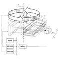
本実施例のX線撮影装置は、図6に示すように、実施例1の構成の、X線源1、スリットレンズ3及びFPDを一つのユニットとして、軸8を回転中心軸として回転させる機構を有するX線CT撮影装置である。回転の角度を精密に制御するための回転制御部が機構として加えられている。回転制御部によって制御される回転角に応じて、被写体を透過したX線の強度がFPDで検出される。画像構築部は、回転角に応じて得られたX線の強度に基づいて、被写体の3次元の画像を構築する。スリットレンズ3で平行化されたX線の出射方向に対する法線方向を回転軸としている。
[Example 2]
As shown in FIG. 6, the X-ray imaging apparatus of the present embodiment is a mechanism that rotates the
本実施例のX線撮影装置においては、まず制御部がX線発生部、画像構築部、回転制御部に対して初期化を行い、次にX線発生部からの制御により所定時間X線を発生させ、FPDは発生終了までX線画像情報を蓄積する。X線発生終了のタイミングでFPDから信号を取り込む。次のステップとして、前述のユニットを所定の角度だけ回転させる。1回の回転角度は必要とされる画像の構築に必要な任意の角度で決められるが、一般的に1回の回転角度は1〜10度程度である。所定角度移動後、再度、X線発生及び取り込みを必要数繰り返す。全ての画像を取り込んだ後、画像を3次元再構築することでCT撮影画像が得られる。 In the X-ray imaging apparatus of the present embodiment, the control unit first initializes the X-ray generation unit, the image construction unit, and the rotation control unit, and then generates X-rays for a predetermined time by control from the X-ray generation unit. The FPD accumulates X-ray image information until the generation ends. A signal is fetched from the FPD at the end of X-ray generation. As the next step, the aforementioned unit is rotated by a predetermined angle. One rotation angle is determined by an arbitrary angle necessary for constructing a required image. Generally, one rotation angle is about 1 to 10 degrees. After moving by a predetermined angle, X-ray generation and capture are repeated again as many times as necessary. After all the images are captured, a CT image is obtained by three-dimensional reconstruction of the images.
尚、本実施例では、被写体の体軸と前述のユニットの回転軸を合わせているが、CT撮影においては必ずしも両方の軸を一致させる必要はなく、本構成に限定されない。 In the present embodiment, the body axis of the subject and the rotation axis of the above-described unit are aligned. However, in CT imaging, it is not always necessary to match both axes, and the present invention is not limited to this configuration.
[実施例3]
本実施例のX線撮影装置は、図7に示すように、実施例2の構成に、並進機構を付与したX線CT撮影装置である。X線源1、スリットレンズ3、FPDを一つのユニットとして、軸8を回転中心軸として回転させる機構と、前述のユニットを被写体の体軸8と同じ方向に移動させる並進移動機構を有する。即ち、回転と並進移動を制御する回転・並進制御部を有する。回転の角度移動と同期して並進移動を行うことで、結果的にらせん状に移動する。回転・並進制御部によって制御される回転角と移動距離とに応じて、被写体を透過したX線の強度がFPDで検出される。画像構築部は、回転角と移動距離とに応じて得られたX線の強度に基づいて、被写体の3次元の画像を構築する。
[Example 3]
As shown in FIG. 7, the X-ray imaging apparatus of the present embodiment is an X-ray CT imaging apparatus in which a translation mechanism is added to the configuration of the second embodiment. The
本実施例のX線撮影装置においては、まず制御部がX線発生部、画像構築部、回転・並進制御部に対して初期化を行い、次にX線発生部からの制御により所定時間X線を発生させ、FPDは発生終了までX線画像情報を蓄積する。X線発生終了のタイミングでFPDから信号を取り込む。次のステップとして、前述のユニットを所定の角度だけ回転させるとともに軸方向に所定距離移動させる。1回の回転角度は必要とされる画像の構築に必要な任意の角度で決められるが、一般的に1回の回転角度は1〜10度程度である。また、1回の並進移動距離はスリットレンズ3の出口側の厚さに依存するが、必要とされる画像の構築に必要な任意の移動量で決められる。所定角度、所定量並進移動後、再度、X線発生及び取り込みを必要数繰り返す。全ての画像を取り込んだ後、画像を3次元再構築することでCT撮影画像が得られる。
In the X-ray imaging apparatus according to the present embodiment, the control unit first initializes the X-ray generation unit, the image construction unit, and the rotation / translation control unit, and then controls the X-ray generation unit for a predetermined time X. A line is generated, and the FPD accumulates X-ray image information until the generation ends. A signal is fetched from the FPD at the end of X-ray generation. As the next step, the aforementioned unit is rotated by a predetermined angle and moved in the axial direction by a predetermined distance. One rotation angle is determined by an arbitrary angle necessary for constructing a required image. Generally, one rotation angle is about 1 to 10 degrees. Further, the translational movement distance of one time depends on the thickness of the exit side of the
[実施例4]
本実施例のX線撮影装置は、図8に示すように、実施例2の構成において、X線源1とスリットレンズ3を一つの照射ユニットとして一体化し、この照射ユニットを回転軸方向に間隔を空けて複数配置したX線CT撮影装置である。複数の照射ユニットと1個のFPDを一体の検出系として、軸8を回転中心軸として回転させる機構を有する。
[Example 4]
As shown in FIG. 8, the X-ray imaging apparatus of the present embodiment integrates the
本実施例のX線撮影装置においては、まず制御部が複数のX線発生部、画像構築部、回転制御部に対して初期化を行い、次にX線発生部からの制御により複数のX線源1に対して同時に所定時間X線を発生させ、FPDは発生終了までX線画像情報を蓄積する。X線発生終了のタイミングでFPDから信号を取り込む。次のステップとして、前述の照射ユニットを所定の角度だけ回転させる。1回の回転角度は必要とされる画像の構築に必要な任意の角度で決められるが、一般的に1回の回転角度は1〜10度程度である。所定角度移動後、再度、X線発生及び取り込みを必要数繰り返す。全ての画像を取り込んだ後、画像を3次元再構築することでCT撮影画像が得られる。
In the X-ray imaging apparatus of the present embodiment, the control unit first initializes the plurality of X-ray generation units, the image construction unit, and the rotation control unit, and then controls the plurality of X-rays by control from the X-ray generation unit. X-rays are simultaneously generated for a predetermined time with respect to the
1、10、20、30、40、50:X線源、2:X線、3:X線反射構造体、4:X線検出器、5:仮想面、6:仮想面の入口側の接平面、7:被写体、8:被写体の体軸、11:X線反射基板、12:電子線源、13:電子線、14:電子レンズ、15:ターゲット 1, 10, 20, 30, 40, 50: X-ray source, 2: X-ray, 3: X-ray reflection structure, 4: X-ray detector, 5: Virtual plane, 6: Contact on the entrance side of the virtual plane Plane, 7: Subject, 8: Body axis of subject, 11: X-ray reflecting substrate, 12: Electron beam source, 13: Electron beam, 14: Electron lens, 15: Target
Claims (17)
隙間を空けて配置された少なくとも3枚の放射線反射基板を有し、隣り合う前記放射線反射基板の間隙により放射線通路を規定し、前記放射線源から複数の前記放射線通路に入射した放射線のそれぞれが互いに平行化されて前記各放射線通路から出射される放射線反射構造体と、
放射線検出器と、
前記各放射線通路から出射され、前記放射線反射構造体と前記放射線検出器との間に配置された被写体を透過し前記放射線検出器で検出された放射線の強度に基づいて前記被写体の画像を構築する画像構築部とを備える放射線撮影装置であって、
前記放射線反射構造体の前記放射線が入射される一端面を入口、前記放射線が出射される他端面を出口としたときに、前記入口から前記出口に向かう方向において、複数の前記放射線反射基板の配列ピッチは増加しており、前記放射線反射基板の板厚は、前記配列ピッチの増加に対応して増加している部分を有していることを特徴とする放射線撮影装置。 A radiation source;
A radiation path is defined by a gap between adjacent radiation reflection boards, and each of the radiation incident on the plurality of radiation paths from the radiation source is mutually A radiation reflecting structure that is collimated and emitted from each of the radiation paths;
A radiation detector;
An image of the subject is constructed based on the intensity of the radiation emitted from each of the radiation paths and transmitted through the subject disposed between the radiation reflecting structure and the radiation detector. A radiographic apparatus comprising an image construction unit,
Arrangement of a plurality of radiation reflecting substrates in a direction from the inlet toward the outlet when the one end surface where the radiation is incident is an entrance and the other end surface where the radiation is emitted is an outlet The radiation imaging apparatus according to claim 1, wherein the pitch is increased, and the thickness of the radiation reflecting substrate has a portion that increases corresponding to the increase in the arrangement pitch.
Δp=L3×(s+g)/L1
であることを特徴とする請求項1又は2に記載の放射線撮影装置。 The distance of the opposite direction L 3 of the radiation detector and the outlet, the source size s of the radiation source, between gap between the radiation reflective substrate adjacent g, the opposing direction of said inlet and said radiation source When the distance is L 1 , the penumbra amount Δ p of the subject formed on the radiation detector is
Δ p = L 3 × (s + g) / L 1
The radiation imaging apparatus according to claim 1, wherein the radiation imaging apparatus is a
0.5×Δd<L3×(s+g)/L1<2×Δd
であることを特徴とする請求項1又は2に記載の放射線撮影装置。 The radiation detector of the pixel size delta d, opposing direction of the distance L 3 between the radiation detector and the outlet, the source size s of the radiation source, between gap between the radiation reflective substrate adjacent g, When the distance between the opposing direction between the radiation source and the inlet to L 1,
0.5 × Δ d <L 3 × (s + g) / L 1 <2 × Δ d
The radiation imaging apparatus according to claim 1, wherein the radiation imaging apparatus is a
(s+g)/L1、Δd/L3
のうちの大きい方よりも小さいことを特徴とする請求項1又は2に記載の放射線撮影装置。 The source size s of the radiation source, g between gap between the radiation reflective substrate adjacent, L 1 the distance of the opposite direction of the radiation source and the inlet, the pixel size of the radiation detector delta d, wherein When the distance in the opposite direction between the exit and the radiation detector is L 3 , the parallelism Δ out of all the radiation reflecting substrates is
(S + g) / L 1 , Δ d / L 3
The radiation imaging apparatus according to claim 1, wherein the radiation imaging apparatus is smaller than a larger one of the two.
Δs<L1×θc
であることを特徴とする請求項3乃至5のいずれか1項に記載の放射線撮影装置。 When the distance in the facing direction between the radiation source and the entrance is L 1 , and the critical angle of the viewing angle when radiation is incident on each radiation path is θ c , the facing between the radiation source and the radiation path is The distance Δ s in the direction perpendicular to the direction is
Δ s <L 1 × θ c
The radiation imaging apparatus according to claim 3, wherein:
前記回転制御部によって制御される回転角に応じて、前記被写体を透過した前記放射線の強度が前記放射線検出器で検出されることを特徴とする請求項1乃至11のいずれか1項に記載の放射線撮影装置。 The subject is arranged at a position overlapping the rotation axis with the direction orthogonal to the emission direction of the collimated radiation as a rotation axis, and the radiation source, the radiation reflection structure, and the radiation detector are integrated. And a rotation control unit that rotates about the rotation axis.
The intensity of the radiation transmitted through the subject is detected by the radiation detector according to a rotation angle controlled by the rotation control unit. Radiography equipment.
前記回転・並進制御部によって制御される回転角と移動距離とに応じて、前記被写体を透過した前記放射線の強度が前記放射線検出器で検出されることを特徴とする請求項1乃至13のいずれか1項に記載の放射線撮影装置。 The subject is arranged at a position overlapping the rotation axis with the direction orthogonal to the emission direction of the collimated radiation as a rotation axis, and the radiation source, the radiation reflection structure, and the radiation detector are integrated. And a rotation / translation control unit that moves in the direction along the rotation axis while rotating around the rotation axis.
The intensity of the radiation transmitted through the subject is detected by the radiation detector according to a rotation angle and a movement distance controlled by the rotation / translation control unit. The radiation imaging apparatus of Claim 1.
Priority Applications (2)
| Application Number | Priority Date | Filing Date | Title |
|---|---|---|---|
| JP2012055717A JP6108671B2 (en) | 2012-03-13 | 2012-03-13 | Radiography equipment |
| US13/791,070 US9020098B2 (en) | 2012-03-13 | 2013-03-08 | Radiation imaging apparatus |
Applications Claiming Priority (1)
| Application Number | Priority Date | Filing Date | Title |
|---|---|---|---|
| JP2012055717A JP6108671B2 (en) | 2012-03-13 | 2012-03-13 | Radiography equipment |
Publications (3)
| Publication Number | Publication Date |
|---|---|
| JP2013190269A JP2013190269A (en) | 2013-09-26 |
| JP2013190269A5 JP2013190269A5 (en) | 2015-04-23 |
| JP6108671B2 true JP6108671B2 (en) | 2017-04-05 |
Family
ID=49157649
Family Applications (1)
| Application Number | Title | Priority Date | Filing Date |
|---|---|---|---|
| JP2012055717A Expired - Fee Related JP6108671B2 (en) | 2012-03-13 | 2012-03-13 | Radiography equipment |
Country Status (2)
| Country | Link |
|---|---|
| US (1) | US9020098B2 (en) |
| JP (1) | JP6108671B2 (en) |
Families Citing this family (3)
| Publication number | Priority date | Publication date | Assignee | Title |
|---|---|---|---|---|
| JP2013128661A (en) | 2011-12-21 | 2013-07-04 | Canon Inc | Stereo x-ray imaging apparatus and stereo x-ray imaging method |
| JP6016386B2 (en) | 2012-03-09 | 2016-10-26 | キヤノン株式会社 | X-ray optical device |
| JP6579652B2 (en) * | 2015-06-22 | 2019-09-25 | 幸則 永谷 | X-ray fluoroscope |
Family Cites Families (31)
| Publication number | Priority date | Publication date | Assignee | Title |
|---|---|---|---|---|
| JPH0219760Y2 (en) * | 1981-06-15 | 1990-05-30 | ||
| JPH02501338A (en) * | 1986-08-15 | 1990-05-10 | コモンウェルス サイエンティフィック アンド インダストリアル リサーチ オーガナイゼイション | Instrumentation for X-ray or neutron beam adjustment |
| EP0555376B1 (en) * | 1990-10-31 | 1998-03-18 | X-Ray Optical Systems, Inc. | Device for controlling radiation and uses thereof |
| EP0723272B1 (en) * | 1994-07-08 | 2001-04-25 | Muradin Abubekirovich Kumakhov | Method of guiding beams of neutral and charged particles and a device for implementing said method |
| US5570408A (en) * | 1995-02-28 | 1996-10-29 | X-Ray Optical Systems, Inc. | High intensity, small diameter x-ray beam, capillary optic system |
| US7104686B2 (en) | 2001-05-30 | 2006-09-12 | Canon Kabushiki Kaisha | Radiographic apparatus |
| US6782076B2 (en) * | 2001-12-07 | 2004-08-24 | Bede Scientific Instruments Limited | X-ray topographic system |
| JP3639826B2 (en) | 2002-04-03 | 2005-04-20 | キヤノン株式会社 | Radiation imaging apparatus, program, computer-readable storage medium, and radiation imaging system |
| JP2004089445A (en) | 2002-08-30 | 2004-03-25 | Konica Minolta Holdings Inc | X ray generating apparatus and x-ray image photographing system |
| JP4439882B2 (en) | 2003-11-14 | 2010-03-24 | キヤノン株式会社 | Radiation image processing apparatus and processing method |
| JP4549093B2 (en) | 2004-04-12 | 2010-09-22 | キヤノン株式会社 | Image processing apparatus and method, and program |
| JP4497997B2 (en) | 2004-04-21 | 2010-07-07 | キヤノン株式会社 | Radiation imaging apparatus and control method thereof |
| EP1922756B1 (en) * | 2005-08-26 | 2013-05-22 | Philips Intellectual Property & Standards GmbH | Electrically shielded through-wafer interconnect |
| JP4878311B2 (en) | 2006-03-03 | 2012-02-15 | キヤノン株式会社 | Multi X-ray generator |
| US7742566B2 (en) | 2007-12-07 | 2010-06-22 | General Electric Company | Multi-energy imaging system and method using optic devices |
| JP5294653B2 (en) | 2008-02-28 | 2013-09-18 | キヤノン株式会社 | Multi X-ray generator and X-ray imaging apparatus |
| JP5398157B2 (en) | 2008-03-17 | 2014-01-29 | キヤノン株式会社 | X-ray imaging apparatus and control method thereof |
| JP5361336B2 (en) | 2008-11-06 | 2013-12-04 | キヤノン株式会社 | X-ray mammography device |
| JP5247363B2 (en) | 2008-11-11 | 2013-07-24 | キヤノン株式会社 | X-ray equipment |
| JP5455446B2 (en) * | 2009-06-02 | 2014-03-26 | キヤノン株式会社 | Radiation imaging apparatus, control method and program for radiation imaging apparatus |
| JP5576631B2 (en) | 2009-09-09 | 2014-08-20 | キヤノン株式会社 | Radiographic apparatus, radiographic method, and program |
| JP2011122826A (en) * | 2009-12-08 | 2011-06-23 | Yokogawa Electric Corp | X-ray irradiation device |
| JP5416006B2 (en) | 2010-03-23 | 2014-02-12 | キヤノン株式会社 | X-ray generator and control method thereof |
| US8311184B2 (en) * | 2010-08-30 | 2012-11-13 | General Electric Company | Fan-shaped X-ray beam imaging systems employing graded multilayer optic devices |
| JP5661432B2 (en) | 2010-11-17 | 2015-01-28 | キヤノン株式会社 | X-ray generator |
| JP5800578B2 (en) | 2011-05-31 | 2015-10-28 | キヤノン株式会社 | X-ray tube |
| JP2013002887A (en) | 2011-06-14 | 2013-01-07 | Canon Inc | Radiation detection panel and radiographic device |
| JP5956727B2 (en) | 2011-06-29 | 2016-07-27 | キヤノン株式会社 | X-ray equipment |
| JP5804821B2 (en) | 2011-07-25 | 2015-11-04 | キヤノン株式会社 | Radiation imaging apparatus and control method thereof |
| JP2013128661A (en) | 2011-12-21 | 2013-07-04 | Canon Inc | Stereo x-ray imaging apparatus and stereo x-ray imaging method |
| JP5988598B2 (en) | 2012-01-31 | 2016-09-07 | キヤノン株式会社 | Subject information acquisition apparatus and subject information acquisition method |
-
2012
- 2012-03-13 JP JP2012055717A patent/JP6108671B2/en not_active Expired - Fee Related
-
2013
- 2013-03-08 US US13/791,070 patent/US9020098B2/en not_active Expired - Fee Related
Also Published As
| Publication number | Publication date |
|---|---|
| US20130243156A1 (en) | 2013-09-19 |
| US9020098B2 (en) | 2015-04-28 |
| JP2013190269A (en) | 2013-09-26 |
Similar Documents
| Publication | Publication Date | Title |
|---|---|---|
| TWI607288B (en) | Optical characterization systems employing compact synchrotron radiation sources | |
| US8073099B2 (en) | Differential interference phase contrast X-ray imaging system | |
| US6389101B1 (en) | Parallel x-ray nanotomography | |
| US6895080B2 (en) | X-ray measuring apparatus | |
| CN108369281A (en) | High DQE imaging devices | |
| JP6189294B2 (en) | Phase imaging | |
| JP6016389B2 (en) | X-ray optical apparatus adjustment method | |
| US11573392B2 (en) | Imaging device, image generating device, and imaging method | |
| JP6108671B2 (en) | Radiography equipment | |
| JP7252938B2 (en) | Focused X-ray Imaging Apparatus and Method | |
| CN110786874A (en) | X-ray system and method for operating an X-ray system | |
| US11000249B2 (en) | X-ray detector for grating-based phase-contrast imaging | |
| JP6016386B2 (en) | X-ray optical device | |
| US10925556B2 (en) | Imaging with modulated X-ray radiation | |
| Chai et al. | Extreme ultra-violet movie camera for imaging microsecond time scale magnetic reconnection | |
| CN107847200B (en) | Imaging apparatus and system with enhanced X-ray radiation | |
| WO2017002830A1 (en) | Radiation measuring apparatus | |
| Li et al. | Study on full-aperture intensity response measurement for x-ray Kirkpatrick–Baez microscope | |
| Nikitin et al. | Scattered radiation suppression by means of X-ray capillary systems | |
| Fisher | Summary of the 2014 Beam-Halo Monitoring Workshop | |
| JP2012170645A (en) | X-ray imaging apparatus, and x-ray imaging method |
Legal Events
| Date | Code | Title | Description |
|---|---|---|---|
| A521 | Request for written amendment filed |
Free format text: JAPANESE INTERMEDIATE CODE: A523 Effective date: 20150309 |
|
| A621 | Written request for application examination |
Free format text: JAPANESE INTERMEDIATE CODE: A621 Effective date: 20150309 |
|
| A977 | Report on retrieval |
Free format text: JAPANESE INTERMEDIATE CODE: A971007 Effective date: 20160112 |
|
| A131 | Notification of reasons for refusal |
Free format text: JAPANESE INTERMEDIATE CODE: A131 Effective date: 20160119 |
|
| A521 | Request for written amendment filed |
Free format text: JAPANESE INTERMEDIATE CODE: A523 Effective date: 20160318 |
|
| A131 | Notification of reasons for refusal |
Free format text: JAPANESE INTERMEDIATE CODE: A131 Effective date: 20160726 |
|
| A521 | Request for written amendment filed |
Free format text: JAPANESE INTERMEDIATE CODE: A523 Effective date: 20160923 |
|
| TRDD | Decision of grant or rejection written | ||
| A01 | Written decision to grant a patent or to grant a registration (utility model) |
Free format text: JAPANESE INTERMEDIATE CODE: A01 Effective date: 20170207 |
|
| A61 | First payment of annual fees (during grant procedure) |
Free format text: JAPANESE INTERMEDIATE CODE: A61 Effective date: 20170307 |
|
| R151 | Written notification of patent or utility model registration |
Ref document number: 6108671 Country of ref document: JP Free format text: JAPANESE INTERMEDIATE CODE: R151 |
|
| LAPS | Cancellation because of no payment of annual fees |