JP6108310B2 - Wireless power transmission device - Google Patents
Wireless power transmission device Download PDFInfo
- Publication number
- JP6108310B2 JP6108310B2 JP2013520657A JP2013520657A JP6108310B2 JP 6108310 B2 JP6108310 B2 JP 6108310B2 JP 2013520657 A JP2013520657 A JP 2013520657A JP 2013520657 A JP2013520657 A JP 2013520657A JP 6108310 B2 JP6108310 B2 JP 6108310B2
- Authority
- JP
- Japan
- Prior art keywords
- transmission
- power
- frequency
- antenna
- power transmission
- Prior art date
- Legal status (The legal status is an assumption and is not a legal conclusion. Google has not performed a legal analysis and makes no representation as to the accuracy of the status listed.)
- Active
Links
Images


Classifications
-
- B—PERFORMING OPERATIONS; TRANSPORTING
- B60—VEHICLES IN GENERAL
- B60L—PROPULSION OF ELECTRICALLY-PROPELLED VEHICLES; SUPPLYING ELECTRIC POWER FOR AUXILIARY EQUIPMENT OF ELECTRICALLY-PROPELLED VEHICLES; ELECTRODYNAMIC BRAKE SYSTEMS FOR VEHICLES IN GENERAL; MAGNETIC SUSPENSION OR LEVITATION FOR VEHICLES; MONITORING OPERATING VARIABLES OF ELECTRICALLY-PROPELLED VEHICLES; ELECTRIC SAFETY DEVICES FOR ELECTRICALLY-PROPELLED VEHICLES
- B60L53/00—Methods of charging batteries, specially adapted for electric vehicles; Charging stations or on-board charging equipment therefor; Exchange of energy storage elements in electric vehicles
- B60L53/10—Methods of charging batteries, specially adapted for electric vehicles; Charging stations or on-board charging equipment therefor; Exchange of energy storage elements in electric vehicles characterised by the energy transfer between the charging station and the vehicle
- B60L53/12—Inductive energy transfer
-
- H—ELECTRICITY
- H02—GENERATION; CONVERSION OR DISTRIBUTION OF ELECTRIC POWER
- H02J—CIRCUIT ARRANGEMENTS OR SYSTEMS FOR SUPPLYING OR DISTRIBUTING ELECTRIC POWER; SYSTEMS FOR STORING ELECTRIC ENERGY
- H02J50/00—Circuit arrangements or systems for wireless supply or distribution of electric power
- H02J50/10—Circuit arrangements or systems for wireless supply or distribution of electric power using inductive coupling
- H02J50/12—Circuit arrangements or systems for wireless supply or distribution of electric power using inductive coupling of the resonant type
-
- H—ELECTRICITY
- H02—GENERATION; CONVERSION OR DISTRIBUTION OF ELECTRIC POWER
- H02J—CIRCUIT ARRANGEMENTS OR SYSTEMS FOR SUPPLYING OR DISTRIBUTING ELECTRIC POWER; SYSTEMS FOR STORING ELECTRIC ENERGY
- H02J50/00—Circuit arrangements or systems for wireless supply or distribution of electric power
- H02J50/20—Circuit arrangements or systems for wireless supply or distribution of electric power using microwaves or radio frequency waves
-
- H—ELECTRICITY
- H02—GENERATION; CONVERSION OR DISTRIBUTION OF ELECTRIC POWER
- H02J—CIRCUIT ARRANGEMENTS OR SYSTEMS FOR SUPPLYING OR DISTRIBUTING ELECTRIC POWER; SYSTEMS FOR STORING ELECTRIC ENERGY
- H02J50/00—Circuit arrangements or systems for wireless supply or distribution of electric power
- H02J50/80—Circuit arrangements or systems for wireless supply or distribution of electric power involving the exchange of data, concerning supply or distribution of electric power, between transmitting devices and receiving devices
-
- H—ELECTRICITY
- H02—GENERATION; CONVERSION OR DISTRIBUTION OF ELECTRIC POWER
- H02J—CIRCUIT ARRANGEMENTS OR SYSTEMS FOR SUPPLYING OR DISTRIBUTING ELECTRIC POWER; SYSTEMS FOR STORING ELECTRIC ENERGY
- H02J7/00—Circuit arrangements for charging or depolarising batteries or for supplying loads from batteries
- H02J7/02—Circuit arrangements for charging or depolarising batteries or for supplying loads from batteries for charging batteries from ac mains by converters
-
- Y—GENERAL TAGGING OF NEW TECHNOLOGICAL DEVELOPMENTS; GENERAL TAGGING OF CROSS-SECTIONAL TECHNOLOGIES SPANNING OVER SEVERAL SECTIONS OF THE IPC; TECHNICAL SUBJECTS COVERED BY FORMER USPC CROSS-REFERENCE ART COLLECTIONS [XRACs] AND DIGESTS
- Y02—TECHNOLOGIES OR APPLICATIONS FOR MITIGATION OR ADAPTATION AGAINST CLIMATE CHANGE
- Y02T—CLIMATE CHANGE MITIGATION TECHNOLOGIES RELATED TO TRANSPORTATION
- Y02T10/00—Road transport of goods or passengers
- Y02T10/60—Other road transportation technologies with climate change mitigation effect
- Y02T10/70—Energy storage systems for electromobility, e.g. batteries
-
- Y—GENERAL TAGGING OF NEW TECHNOLOGICAL DEVELOPMENTS; GENERAL TAGGING OF CROSS-SECTIONAL TECHNOLOGIES SPANNING OVER SEVERAL SECTIONS OF THE IPC; TECHNICAL SUBJECTS COVERED BY FORMER USPC CROSS-REFERENCE ART COLLECTIONS [XRACs] AND DIGESTS
- Y02—TECHNOLOGIES OR APPLICATIONS FOR MITIGATION OR ADAPTATION AGAINST CLIMATE CHANGE
- Y02T—CLIMATE CHANGE MITIGATION TECHNOLOGIES RELATED TO TRANSPORTATION
- Y02T10/00—Road transport of goods or passengers
- Y02T10/60—Other road transportation technologies with climate change mitigation effect
- Y02T10/7072—Electromobility specific charging systems or methods for batteries, ultracapacitors, supercapacitors or double-layer capacitors
-
- Y—GENERAL TAGGING OF NEW TECHNOLOGICAL DEVELOPMENTS; GENERAL TAGGING OF CROSS-SECTIONAL TECHNOLOGIES SPANNING OVER SEVERAL SECTIONS OF THE IPC; TECHNICAL SUBJECTS COVERED BY FORMER USPC CROSS-REFERENCE ART COLLECTIONS [XRACs] AND DIGESTS
- Y02—TECHNOLOGIES OR APPLICATIONS FOR MITIGATION OR ADAPTATION AGAINST CLIMATE CHANGE
- Y02T—CLIMATE CHANGE MITIGATION TECHNOLOGIES RELATED TO TRANSPORTATION
- Y02T90/00—Enabling technologies or technologies with a potential or indirect contribution to GHG emissions mitigation
- Y02T90/10—Technologies relating to charging of electric vehicles
- Y02T90/12—Electric charging stations
-
- Y—GENERAL TAGGING OF NEW TECHNOLOGICAL DEVELOPMENTS; GENERAL TAGGING OF CROSS-SECTIONAL TECHNOLOGIES SPANNING OVER SEVERAL SECTIONS OF THE IPC; TECHNICAL SUBJECTS COVERED BY FORMER USPC CROSS-REFERENCE ART COLLECTIONS [XRACs] AND DIGESTS
- Y02—TECHNOLOGIES OR APPLICATIONS FOR MITIGATION OR ADAPTATION AGAINST CLIMATE CHANGE
- Y02T—CLIMATE CHANGE MITIGATION TECHNOLOGIES RELATED TO TRANSPORTATION
- Y02T90/00—Enabling technologies or technologies with a potential or indirect contribution to GHG emissions mitigation
- Y02T90/10—Technologies relating to charging of electric vehicles
- Y02T90/14—Plug-in electric vehicles
Landscapes
- Engineering & Computer Science (AREA)
- Power Engineering (AREA)
- Computer Networks & Wireless Communication (AREA)
- Transportation (AREA)
- Mechanical Engineering (AREA)
- Charge And Discharge Circuits For Batteries Or The Like (AREA)
- Near-Field Transmission Systems (AREA)
- Transmitters (AREA)
Description
本発明は、共振磁界結合を利用して電力を無線で伝送する共振磁界結合型の非接触電力技術に関する。 The present invention relates to a resonance magnetic field coupling type non-contact power technology that wirelessly transmits power using resonance magnetic field coupling.
特許文献1は、2つの共振器の間で空間を介してエネルギーを伝送する新しい無線エネルギー伝送装置を開示している。この無線エネルギー伝送装置では、共振器の周辺の空間に生じる共振周波数の振動エネルギーのしみ出し(エバネッセント・テール)を介して2つの共振器を結合することにより、振動エネルギーを無線(非接触)で伝送する。 Patent Document 1 discloses a new wireless energy transmission device that transmits energy between two resonators via a space. In this wireless energy transmission device, vibration energy is transmitted wirelessly (contactlessly) by coupling two resonators through the vibration energy exudation (evanescent tail) generated in the space around the resonator. To transmit.
一方で、古くから電磁誘導技術が存在する。これらの電力伝送技術が適用される電子機器の中には、一定電圧の電力の入力を受けて、何らかの電力変換や分圧、エネルギー伝送などのブロックを経た後に、機器へ供給する電圧を一定電圧とするよう要求するものが多い。例えばテレビなどのAV機器について説明すると、入力はほぼ一定電圧のAC電力を供給するコンセントから受け、最終的に電力を消費する機器内個別回路は所定の電圧を保って動作する。画面の輝度が変化した場合も電流量を変化させることで対応する。このように一定電圧の電力供給を電源から受け、一定電圧の電力を負荷に出力する動作のことを以後「定電圧動作」と記述することとする。 On the other hand, electromagnetic induction technology has existed for a long time. Some electronic devices to which these power transmission technologies are applied receive a constant voltage of power, and after passing through a block such as some power conversion, voltage division, and energy transmission, the voltage supplied to the device is a constant voltage. There are many things that require For example, an AV device such as a television will be described. An input is received from an outlet that supplies AC power of a substantially constant voltage, and an individual circuit within the device that eventually consumes power operates while maintaining a predetermined voltage. Even when the brightness of the screen changes, it can be dealt with by changing the amount of current. The operation of receiving a constant voltage power supply from the power source and outputting the constant voltage power to the load is hereinafter referred to as “constant voltage operation”.
特許文献1に記載の無線エネルギー伝送回路では、大電力伝送時から小電力伝送時まで定電圧動作を行う際に高効率伝送特性を維持することが困難である。 In the wireless energy transmission circuit described in Patent Document 1, it is difficult to maintain high-efficiency transmission characteristics when performing constant voltage operation from high power transmission to low power transmission.
本発明の実施形態は、大電力伝送時だけでなく小電力伝送時も高い効率を維持することが可能な無線電力伝送装置を提供する。 Embodiments of the present invention provide a wireless power transmission device capable of maintaining high efficiency not only during high power transmission but also during low power transmission.
本発明の無線電力伝送装置の実施形態は、共振磁界結合によって非接触で電力を伝送することができる一対のアンテナであって、一方は共振周波数がfsの直列共振回路であり、他方は共振周波数がfpの並列共振回路である一対のアンテナと、前記一対のアンテナのうち、高周波電力を送る側のアンテナに接続された発振器と、前記一対のアンテナ間を伝送される電力の大きさに応じて伝送周波数を制御する制御部とを備え、前記一対のアンテナ間の結合係数をkとするとき、fs/fp<−0.6074×k2+0.0466×k+0.9955の関係を満たすようにfsおよびfpが設定されている。An embodiment of the wireless power transmission device of the present invention is a pair of antennas that can transmit power in a contactless manner by resonant magnetic field coupling, one of which is a series resonant circuit having a resonant frequency of fs, and the other is a resonant frequency. Depending on the magnitude of the power transmitted between the pair of antennas, a pair of antennas that are parallel resonant circuits of fp, an oscillator connected to the antenna on the high-frequency power transmission side of the pair of antennas, and the pair of antennas And a control unit for controlling a transmission frequency, where fs / fp <−0.6074 × k 2 + 0.0466 × k + 0.9955 is satisfied so that the coupling coefficient between the pair of antennas is k. And fp are set.
本発明の無線電力伝送装置の実施形態によれば、共振磁界結合を利用してアンテナ間の伝送を行う際に、例えば広い伝送電力範囲において、電力伝送装置の高効率化を実現しうる。 According to the embodiment of the wireless power transmission device of the present invention, when performing transmission between antennas using resonant magnetic field coupling, for example, high efficiency of the power transmission device can be realized in a wide transmission power range.
本発明の無線電力伝送装置の実施形態は、図1に示されるように、共振磁界結合によって非接触で高周波(RF)電力を伝送することができる一対のアンテナ(送電アンテナ107および受電アンテナ109)と、高周波電力を送る側の送電アンテナ107に接続された発振器103とを備えている。送電アンテナ107および受電アンテナ109の一方は共振周波数がfsの直列共振回路であり、他方は共振周波数がfpの並列共振回路である。受電アンテナ109は、送電アンテナ107に接触しておらず、送電アンテナ107から例えば数ミリメートル〜数十センチメートル程度は離間している。
As shown in FIG. 1, the embodiment of the wireless power transmission apparatus of the present invention has a pair of antennas (a
この無線電力伝送装置は、さらに、アンテナ107、109間を伝送される高周波電力の周波数(伝送周波数)を制御する制御部(伝送周波数制御部)100を備えている。伝送周波数制御部100は、アンテナ107、109間を伝送される高周波電力の大きさ(伝送電力)に応じて伝送周波数を調整するように構成されている。伝送周波数は、例えば50Hz〜300GHzの範囲内で調整され得る。伝送周波数は、20kHz〜10GHzの範囲内に設定されてもよく、20kHz〜20MHzの範囲内に設定されてもよく、20kHz〜1MHzの範囲内に設定されてもよい。ある実施形態の伝送周波数は、6.78MHzに設定され得る。
The wireless power transmission apparatus further includes a control unit (transmission frequency control unit) 100 that controls the frequency (transmission frequency) of the high-frequency power transmitted between the
発振器103は、図示しない電源から供給される直流または交流のエネルギー(電力)を受け取り、供給されたエネルギーを伝送周波数のRFエネルギーに周波数変換する(DC/RF変換もしくはAC/RF変換)。発振器103は、伝送周波数制御部100に接続されており、伝送周波数制御部100の働きにより、伝送周波数を変化させる。以下、発振器103から出力されたRFエネルギーは送電アンテナ107に入力される。電力伝送時、送電アンテナ107と受電アンテナ109は、互いの共振器が周辺空間に形成する共振磁界を介して磁気的に結合される。受電アンテナ109の出力部は負荷に接続されるが、受電アンテナ109の後段に周波数変換回路が接続されてもよい。
The
本発明の無線電力伝送装置の実施形態における「アンテナ」は、放射電磁界の送受信を行うための通常のアンテナではなく、共振器の電磁界の近傍成分(エバネッセント・テール)の結合を利用して2つの物体間でエネルギー伝送を行うための要素である。共振磁界を利用した無線電力伝送によれば、電磁波を遠方に伝搬させるときに生じるエネルギー損失(放射損失)が生じないため、極めて高い効率で電力を伝送することが可能になる。このような共振電磁界(近接場)の結合を利用したエネルギー伝送では、ファラデーの電磁誘導の法則を利用した公知の無線電力伝送に比べて損失が少ないだけではなく、例えば数メートルも離れた2つの共振器(アンテナ)間で高効率にエネルギーを伝送することが可能になる。 The “antenna” in the embodiment of the wireless power transmission apparatus of the present invention is not a normal antenna for transmitting and receiving a radiated electromagnetic field, but utilizes coupling of components in the vicinity of the electromagnetic field of the resonator (evanescent tail). It is an element for performing energy transfer between two objects. According to wireless power transmission using a resonant magnetic field, energy loss (radiation loss) that occurs when electromagnetic waves are propagated far away does not occur, so that power can be transmitted with extremely high efficiency. The energy transmission using the resonance electromagnetic field (near field) coupling not only has a small loss but also has a distance of, for example, several meters, compared to the known wireless power transmission using Faraday's law of electromagnetic induction. It becomes possible to transmit energy with high efficiency between two resonators (antennas).
このような原理に基づく無線電力伝送を行うには、2つの共振アンテナ間で結合を生じさせる必要がある。fsおよび/またはfpは、伝送周波数と一致する必要は無い。本発明の実施形態では、fsをfpよりも小さな値に設定し、かつ、伝送周波数を伝送電力に応じて変化させる。 In order to perform wireless power transmission based on such a principle, it is necessary to cause coupling between two resonant antennas. fs and / or fp need not match the transmission frequency. In the embodiment of the present invention, fs is set to a value smaller than fp, and the transmission frequency is changed according to the transmission power.
図2は、共振周波数がfsの直列共振回路200と共振周波数がfpの並列共振回路300との間で、結合係数kの共振磁界結合が生じている様子を模式的に示している。
FIG. 2 schematically shows a state in which a resonant magnetic field coupling having a coupling coefficient k is generated between the series
一般的に、固有の共振周波数を有する二つの共振器が電気的に結合した場合、共振周波数が変化することが知られている。仮に2つの共振器の共振周波数が同一であったとしても、上記結合により共振器対としての共振周波数は2つの周波数に分離する。結合共振器対が示す2つの共振周波数の内、周波数が高いものを偶モードの共振周波数(fH)、周波数が低いものを奇モードの共振周波数(fL)と呼ぶ。このとき、共振器間の結合係数kは、以下の式1で表される。
k=(fH2−fL2)÷(fH2+fL2) ・・・(式1)Generally, it is known that when two resonators having a specific resonance frequency are electrically coupled, the resonance frequency changes. Even if the resonance frequencies of the two resonators are the same, the resonance frequency as the resonator pair is separated into two frequencies by the above coupling. Of the two resonance frequencies indicated by the coupled resonator pair, a higher frequency is called an even mode resonance frequency (fH), and a lower frequency is called an odd mode resonance frequency (fL). At this time, the coupling coefficient k between the resonators is expressed by the following Equation 1.
k = (fH 2 −fL 2 ) ÷ (fH 2 + fL 2 ) (Equation 1)
結合が強いほど、kは大きな値となり、2つの共振周波数の分離量が増大する。本発明の実施形態では、kの値を比較的低い値、すなわち、0<k≦0.5の範囲内に、好ましくは0.1≦k≦0.5の範囲内に設定する。kの値は0.5を超えてもよいが、kの値を0.5以下に設定することにより、送受アンテナ間の距離の増大や、送受アンテナ間のサイズ非対称性など、共振磁界結合方式ならではの効果を顕著に得ることが可能になる。 The stronger the coupling is, the larger k becomes, and the amount of separation between the two resonance frequencies increases. In the embodiment of the present invention, the value of k is set to a relatively low value, that is, in the range of 0 <k ≦ 0.5, preferably in the range of 0.1 ≦ k ≦ 0.5. The value of k may exceed 0.5, but by setting the value of k to 0.5 or less, the resonance magnetic field coupling method such as an increase in the distance between the transmitting and receiving antennas and the size asymmetry between the transmitting and receiving antennas A unique effect can be obtained remarkably.
図3Aは、送電アンテナ107が直列共振回路であり、受電アンテナ109が並列共振回路である構成例の等価回路図である。図3Aの構成例における送電アンテナ107は、第1インダクタ107aおよび第1容量素子107bが直列に接続された直列共振回路であり、受電アンテナ109は第2インダクタ109aおよび第2容量素子109bが並列に接続された並列共振回路である。送電アンテナ107の直列共振回路は寄生抵抗成分R1を有し、受電アンテナ109の並列共振回路は寄生抵抗成分R2を有している。本発明の無線電力伝送装置の実施形態では、送電アンテナ107および受電アンテナ109が、直列共振回路および並列共振回路、という非対称な組み合わせで構成されている。本発明は、図3Bに示すように、送電アンテナ107が並列共振回路であり、受電アンテナ109が直列共振回路であってもよい。kの値を0.5以下に設定し、送電アンテナを直列共振回路、受電アンテナを並列共振回路に構成することにより、電力伝送後の受電電圧を上昇させるという効果を顕著に得ることも可能となる。また、kの値を0.5以下に設定し、送電アンテナを並列共振回路、受電アンテナを直列共振回路に構成することにより、電力伝送後の受電電圧を降下させるという効果を顕著に得ることも可能となる。
FIG. 3A is an equivalent circuit diagram of a configuration example in which the
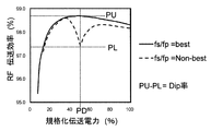
本明細書では、並列共振回路の共振周波数fpに対する直列共振回路の共振周波数fsの比率fs/fpを「共振周波数比」と称することにする。本発明者は、共振周波数比fs/fpを1.0に等しく設定した場合、伝送電力に依存して伝送効率が低下する問題が存在することを見出した。図4Aは、この問題を示すグラフである。このグラフは、fs/fp=1.0の場合において、伝送電力と伝送効率との関係を示している。図のグラフの横軸は、ある伝送電力の値によって規格化された伝送電力(規格化伝送電力:単位は%)である。規格化に用いる値は、任意であるが、例えば伝送される電力の最大値が使用され得る。本明細書では、この「規格化伝送電力」を簡単に「伝送電力」と称する場合がある。図4Aの例では、規格化された伝送電力が約50%のとき、伝送効率の顕著な低下が観察される。このような伝送効率の落ち込みをDipと称する。本発明者は、fs/fpを、結合係数kに応じて選択された最適値に設定することにより、伝送電力の変化に起因する伝送効率の低下を低減できることを見出した。更に、本発明者は、fs/fpが、結合係数kに応じて選択される上記の最適値よりも小さい値に設定された場合でも、伝送電力に応じて伝送周波数を適切に変化させると、伝送効率の低下を抑制できることを見出し、本発明を完成した。 In this specification, the ratio fs / fp of the resonance frequency fs of the series resonance circuit to the resonance frequency fp of the parallel resonance circuit is referred to as “resonance frequency ratio”. The inventor has found that when the resonance frequency ratio fs / fp is set equal to 1.0, there is a problem that the transmission efficiency is lowered depending on the transmission power. FIG. 4A is a graph showing this problem. This graph shows the relationship between transmission power and transmission efficiency when fs / fp = 1.0. The horizontal axis of the graph in the figure represents transmission power normalized by a certain transmission power value (normalized transmission power: unit is%). Although the value used for normalization is arbitrary, for example, the maximum value of transmitted power can be used. In the present specification, this “standardized transmission power” may be simply referred to as “transmission power”. In the example of FIG. 4A, when the normalized transmission power is about 50%, a significant decrease in transmission efficiency is observed. Such a drop in transmission efficiency is referred to as Dip. The present inventor has found that by setting fs / fp to an optimum value selected according to the coupling coefficient k, it is possible to reduce a decrease in transmission efficiency due to a change in transmission power. Further, the inventor appropriately changes the transmission frequency according to the transmission power even when fs / fp is set to a value smaller than the above-described optimum value selected according to the coupling coefficient k. The present inventors have found that the reduction in transmission efficiency can be suppressed and completed the present invention.
図4Bは、fs/fpを、結合係数kによって定まる最適値(kの関数)に設定した無線電力伝送装置について、伝送効率と伝送電力との関係の一例を示すグラフである。図4Bの例では、伝送電力によらず伝送周波数を一定に固定している。図4Aの曲線(破線)と図4Bの曲線(実線)との比較から明らかなように、fs/fpを結合係数kに応じて選択された最適値に設定することにより、伝送電力の変化に起因する伝送効率の低下を抑制することが可能になる。しかし、本発明者は、fs/fpが、結合係数kに応じて選択された最適値(kの関数)から外れている場合でも、伝送電力に応じて伝送周波数を調整することにより、伝送効率の低下を抑制できることを見出した。 FIG. 4B is a graph illustrating an example of a relationship between transmission efficiency and transmission power for a wireless power transmission apparatus in which fs / fp is set to an optimum value (a function of k) determined by a coupling coefficient k. In the example of FIG. 4B, the transmission frequency is fixed regardless of the transmission power. As is clear from the comparison between the curve in FIG. 4A (broken line) and the curve in FIG. 4B (solid line), by setting fs / fp to the optimum value selected according to the coupling coefficient k, the change in transmission power can be reduced. It is possible to suppress the resulting decrease in transmission efficiency. However, even when fs / fp deviates from the optimum value (a function of k) selected according to the coupling coefficient k, the present inventor adjusts the transmission frequency according to the transmission power to thereby improve the transmission efficiency. It was found that the decrease in the temperature can be suppressed.
以下、fs/fpと結合係数kとの関係を説明する。 Hereinafter, the relationship between fs / fp and the coupling coefficient k will be described.
まず、図5を参照する。図5は、横軸が結合係数k、縦軸が共振周波数比fs/fpのグラフである。実線の曲線は、以下の式2で表される二次式である。
fs/fp=F(k)
=−0.6074×k2+0.0466×k+0.9955 ・・・(式2)First, referring to FIG. FIG. 5 is a graph of the coupling coefficient k on the horizontal axis and the resonance frequency ratio fs / fp on the vertical axis. The solid curve is a quadratic expression expressed by the following Expression 2.
fs / fp = F (k)
= −0.6074 × k 2 + 0.0466 × k + 0.9955 (Expression 2)
上記の式2は、結合係数kが与えられたときの最適(best)なfs/fpを与える。ここで、「最適」の意味は、fs/fpを変化させたとき、図4Aに示されるような伝送効率の局所的低下が最も小さくなることである。「最適」は、伝送効率の局所的低下が全く生じないことを意味するわけではない。 Equation 2 above gives the best fs / fp when the coupling coefficient k is given. Here, “optimal” means that when fs / fp is changed, the local decrease in transmission efficiency as shown in FIG. 4A is minimized. “Optimal” does not mean that there is no local reduction in transmission efficiency.
ここで、伝送効率低下の程度を評価するため、「Dip率」という値を導入する。図6は、「Dip率」を説明するためのグラフであり、図4Aの曲線(破線)および図4Bの曲線(実線)の両方を記載している。伝送効率が局所的に低下するDip部分を有する曲線について、伝送効率が局所的に最小になる伝送電力をPD、伝送電力PDにおける伝送効率をPLとする。また、fs/fpが最適化された場合の曲線について、伝送電力PDにおける伝送効率をPUとする。このとき、Dip率は、PU−PLによって表現される。Dip率は0%であることが最も好ましい(best)が、0%である必要はない。 Here, in order to evaluate the degree of reduction in transmission efficiency, a value “Dip rate” is introduced. FIG. 6 is a graph for explaining the “Dip rate”, and describes both the curve (broken line) in FIG. 4A and the curve (solid line) in FIG. 4B. For a curve having a Dip portion where the transmission efficiency decreases locally, the transmission power at which the transmission efficiency is locally minimized is PD, and the transmission efficiency at the transmission power PD is PL. Further, regarding the curve when fs / fp is optimized, the transmission efficiency in the transmission power PD is PU. At this time, the Dip rate is expressed by PU-PL. The dip rate is most preferably 0%, but need not be 0%.
本発明の実施形態によれば、上記の式2で定まる基準値よりも、fs/fpが小さく設定され、伝送周波数を伝送電力に応じて後述するように変化させる。fs/fpが式2のF(k)よりも小さい場合であっても、伝送電力に応じて伝送周波数を適切に調整することにより、Dip率を小さくすることができる。ここで、与えられたkの大きさは、「設計によって予め設定されたkの大きさ」、「アンテナを設置した後、直接に測定されたkの大きさ」、および「アンテナを設置した後、kに依存して変化する物理的パラメータを測定または観測することによって推定されたkの大きさ」を含むものとする。 According to the embodiment of the present invention, fs / fp is set to be smaller than the reference value determined by Equation 2 above, and the transmission frequency is changed as described later according to the transmission power. Even when fs / fp is smaller than F (k) in Expression 2, the Dip rate can be reduced by appropriately adjusting the transmission frequency according to the transmission power. Here, the magnitude of k given is “the magnitude of k preset by design”, “the magnitude of k measured directly after installing the antenna”, and “after installing the antenna” , The magnitude of k estimated by measuring or observing physical parameters that vary depending on k.
図1に示される例では、発振器103に接続された伝送周波数制御部100が、アンテナ間の伝送電力の大きさに応じて伝送周波数を制御する。伝送周波数の変化を説明する際の分かりやすさのため、基準となる周波数f0を導入する。ここで、周波数f0は、fs/fpが最適化された場合において、伝送電力が最大値になるときの伝送周波数である。本実施形態では、前述したように、fs/fpの値が図5の曲線よりも下側に位置するように共振周波数fs、fpが設定されている。
In the example shown in FIG. 1, the transmission
本実施形態の伝送周波数制御部100は、アンテナ107、109間を伝送される電力が基準値P1よりも低いとき、伝送周波数を周波数f0よりも高い第1周波数範囲内の値に設定する。そして伝送電力が基準値P1よりも高いときは、伝送周波数を第1周波数範囲よりも低い第2周波数範囲内の値に設定する。この基準値P1は、最大伝送電力Pmaxよりも低く設定された値であり、好ましくは、最大伝送電力Pmaxの30%以上80%以下の範囲に設定され得る。送受アンテナ間の共振磁界の結合モードを切り替えることにより、伝送効率を高く維持することが可能になる。
When the power transmitted between the
伝送周波数制御部100は、例えば、発振器103の発振周波数を制御するための信号(例えば周波数可変のパルス列)を生成し、発振器103に入力する。本実施形態では、図7に示すように、受電アンテナ109の出力は負荷111に接続されている。この負荷111の状況(例えば消費される電力)に応じて、送電アンテナ107から受電アンテナ109に伝送すべき電力の大きさが変化し得る。図7の例では、負荷111が必要とする伝送電力の大きさを示す情報または信号が、負荷111から制御部100に与えられる。これに応答して、制御部100は発振器103の発振周波数を増減させることができる。この結果、伝送周波数が制御されることになる。
The transmission
また、本発明の別の実施形態では、図8に示すように、発振器103が発電部102に接続され、周波数制御部100は発電部102の状況に応じて発振器103の発振周波数を変化させることができる。発電部102は、例えば太陽電池などの発電素子を含んでいる。発電部102から発振器103に供給される電力は、発電部102の状況に応じて変化し得る。例えば、太陽電池が受ける太陽光の量に応じて発生する電力が変化し得る。このため、送電アンテナ107から受電アンテナ109に伝送すべき電力の大きさも変化し得る。図8の例では、発電部102で発電される電力、すなわち伝送電力の大きさを示す情報または信号が、発電部102から制御部100に与えられる。これに応答して、伝送周波数制御部100は発振器103の発振周波数を増減させることができる。この結果、伝送周波数が制御されることになる。
In another embodiment of the present invention, as shown in FIG. 8, the
後述するように、伝送効率を低下させないように伝送周波数を伝送電力に応じて変化させるときの伝送周波数の伝送電力依存性は、予め実験などに基づいて決定され、無線電力伝送装置または負荷に設けられたメモリに記録されていてもよい。また、伝送電力の大きさと伝送周波数との関係は、実際の電力伝送中に、伝送効率に基づいて決定されてもよい。一般に、fs/fpの値は、送電アンテナ107および受電アンテナ109を製造するときに所定の大きさ(設計値)に設定されるが、fs/fpの実際の値は、設計値からずれている可能性がある。したがって、無線電力伝送装置の設置後におけるfs/fpの正確な値は不明になることがあり得る。そのような場合は、無線電力伝送装置の設置後に、実際に無線で電力を伝送し、Dip率が充分に小さくなるような伝送電力と伝送周波数との関係を決定すればよい。
As will be described later, the transmission power dependency of the transmission frequency when changing the transmission frequency according to the transmission power so as not to reduce the transmission efficiency is determined based on experiments in advance and is provided in the wireless power transmission apparatus or the load. May be recorded in the recorded memory. Further, the relationship between the magnitude of transmission power and the transmission frequency may be determined based on transmission efficiency during actual power transmission. In general, the value of fs / fp is set to a predetermined size (design value) when manufacturing the
図9Aは、伝送電力と伝送周波数との関係の一例を示すグラフである。図示される例では、第1周波数範囲での周波数は周波数f0よりも高く設定される。この例では、第1周波数範囲は、周波数f0から偶モード共振周波数fHまでの範囲であり、第2周波数範囲は、奇モード共振周波数fLから周波数f0までの範囲である。偶モードおよび奇モードの共振周波数fH、fLは、前述した通りであり。 FIG. 9A is a graph showing an example of the relationship between transmission power and transmission frequency. In the illustrated example, the frequency in the first frequency range is set higher than the frequency f0. In this example, the first frequency range is a range from the frequency f0 to the even mode resonance frequency fH, and the second frequency range is a range from the odd mode resonance frequency fL to the frequency f0. The even-mode and odd-mode resonance frequencies fH and fL are as described above.
制御部100は、伝送電力が基準値P1よりも高い値から前記基準値P1よりも低い値に変化したとき、または、前記電力が前記基準値P1よりも低い値から前記基準値P1よりも高い値に変化したとき、伝送周波数を、第1周波数範囲内の値と前記第2周波数範囲内の値との間でホッピングさせる。制御部100は、伝送周波数をホッピングさせるとき、一対のアンテナ間を結合する共振磁界のモードを偶モードと奇モードとの間で切り替える。伝送電力と伝送周波数との関係は、図9Aの例に限定されない。図9Bは、より複雑な関係の一例を示している。この例では、基準値P1と基準値P2との間で伝送周波数は最も高い値を有している。基準値P1、P2は、結合係数kによって異なる値を有していてもよい。
When the transmission power changes from a value higher than the reference value P1 to a value lower than the reference value P1, or when the power is lower than the reference value P1 or higher than the reference value P1 When the value changes, the transmission frequency is hopped between a value in the first frequency range and a value in the second frequency range. When hopping the transmission frequency, the
伝送電力の大きさと伝送周波数との関係、および基準値P1、P2などの値は、与えられた伝送電力の大きさのもとで伝送効率を最適化する伝送周波数を決定することによって得られる。伝送電力の大きさと伝送周波数との関係の具体例については、後に詳しく説明する。なお、一対のアンテナの結合係数kは、電力伝送中に一定に維持され得る。 The relationship between the magnitude of the transmission power and the transmission frequency, and the values such as the reference values P1 and P2 are obtained by determining the transmission frequency that optimizes the transmission efficiency based on the given magnitude of the transmission power. A specific example of the relationship between the magnitude of transmission power and the transmission frequency will be described in detail later. Note that the coupling coefficient k of the pair of antennas can be kept constant during power transmission.
無線電力伝送装置においては、伝送電力Pが最大(Pmax)となる動作条件において、高い伝送効率が維持されるべきであることはいうまでもないが、伝送電力を低減した伝送条件においてもやはり効率は高く維持されるべきである。更に、伝送電力がP=Pmaxの場合も、P≠Pmaxの場合でも、定電圧動作を行うことができる。そこで、P=Pmaxの条件での入出力インピーダンスZin(P=Pmax)、Zout(P=Pmax)と任意の伝送電力P伝送時の入出力インピーダンスZin、Zoutの間には、以下の関係が成立する。
Zin=Zin(P=Pmax)×(Pmax÷P) ・・・(式4)
Zout=Zout(P=Pmax)×(Pmax÷P) ・・・(式5)In the wireless power transmission device, it is needless to say that high transmission efficiency should be maintained under the operating condition in which the transmission power P is maximum (Pmax), but it is also efficient under the transmission condition in which the transmission power is reduced. Should be kept high. Furthermore, the constant voltage operation can be performed both when the transmission power is P = Pmax and when P ≠ Pmax. Therefore, the following relationship is established between the input / output impedances Zin (P = Pmax) and Zout (P = Pmax) under the condition of P = Pmax and the input / output impedances Zin and Zout at an arbitrary transmission power P transmission. To do.
Zin = Zin (P = Pmax) × (Pmax ÷ P) (Formula 4)
Zout = Zout (P = Pmax) × (Pmax ÷ P) (Formula 5)
すなわち、定電圧動作中、入出力インピーダンスは伝送電力に反比例して変化する。この条件下において、広い伝送電力範囲で伝送効率を高く維持することが可能になる。この目的を達成するために、本発明の無線電力伝送装置の実施形態における伝送周波数ftrは、電力の伝送量に応じて周波数fLより大きくfHより小さい範囲内で可変制御される。 That is, during the constant voltage operation, the input / output impedance changes in inverse proportion to the transmission power. Under this condition, it is possible to maintain high transmission efficiency over a wide transmission power range. In order to achieve this object, the transmission frequency ftr in the embodiment of the wireless power transmission apparatus of the present invention is variably controlled within a range larger than the frequency fL and smaller than fH according to the amount of power transmission.
なお、この現象は、直列共振回路と並列共振回路という非対称な共振回路構造の組み合わせで送受アンテナを構成した場合に限られる。すなわち、送受アンテナが共に直列共振回路対や並列共振回路対で構成された場合は、本願発明の効果は発現しない。また、送受アンテナが共に、外部回路から電磁誘導原理を利用してエネルギー供給を受ける回路構成(「電磁誘導給電型」と以下記述)の場合も、本願発明の効果は発現しない。更には直列共振回路と電磁誘導給電型、並列共振回路と電磁誘導給電型、のハイブリッドな組み合わせの共振器対においても、本願発明の効果は発現しない。 This phenomenon is limited to the case where the transmission / reception antenna is configured by a combination of an asymmetric resonance circuit structure of a series resonance circuit and a parallel resonance circuit. That is, when both the transmitting and receiving antennas are constituted by a series resonant circuit pair or a parallel resonant circuit pair, the effect of the present invention is not exhibited. In addition, the effects of the present invention do not appear even when both the transmitting and receiving antennas have a circuit configuration that receives energy supply from an external circuit using the principle of electromagnetic induction (hereinafter referred to as “electromagnetic induction feeding type”). Further, the effect of the present invention is not exhibited even in a resonator combination of a hybrid combination of a series resonance circuit and an electromagnetic induction power supply type, and a parallel resonance circuit and an electromagnetic induction power supply type.
P1の値は、例えばPmaxの30%から80%程度の電力値に設定され得る。ただし、P1の値は、この範囲内に限定されず、状況に応じて上記の範囲から外れてもよい。 The value of P1 can be set to a power value of about 30% to 80% of Pmax, for example. However, the value of P1 is not limited to this range, and may be out of the above range depending on the situation.
伝送周波数の可変制御は、発振器103の発振周波数を制御することにより、容易に実現できる。
The variable control of the transmission frequency can be easily realized by controlling the oscillation frequency of the
電力伝送中、送電アンテナと受電アンテナ間の結合係数kがほぼ一定に維持されることが望ましい。電力伝送中に結合係数kが大きく変動すると、定電圧動作を高い効率で実現することが困難になるからである。 It is desirable that the coupling coefficient k between the power transmitting antenna and the power receiving antenna is maintained substantially constant during power transmission. This is because if the coupling coefficient k fluctuates greatly during power transmission, it is difficult to realize constant voltage operation with high efficiency.
発振器103には、D級、E級、F級などの、高効率且つ低歪な特性を実現できる増幅器を用いることができるし、ドハーティ増幅器を用いてもよい。インバータ回路など歪成分を含む出力信号を発生するスイッチング素子の後段に、低域通過フィルタ、帯域阻止フィルタ、または帯域通過フィルタを配置することにより、正弦波を高効率に生成してもよい。AC入力から高周波出力を行う周波数変換回路であってもかまわない。この際、無線伝送部が帯域通過フィルタの機能を兼用してもよい。いずれにしろ発振器に入力された電力はRFエネルギーに変換される。このRFエネルギーは、無線伝送部により、空間を介して非接触に伝送され、出力端子から出力される。
As the
回路ブロック間でのRFエネルギーの多重反射を抑圧し、総合伝送効率を改善するためには、受電アンテナ109の出力端子が負荷に接続された状態において、発振器103から出力されるRFエネルギーの出力インピ−ダンスZocと送電アンテナ107の入力インピーダンスZinとを等しくすることができる。また、同様に、発振器103が送電アンテナ107に接続された状態で、受電アンテナの出力インピーダンスZoutが、接続される負荷の抵抗値Rと等しくすることができる。
In order to suppress the multiple reflection of RF energy between circuit blocks and improve the overall transmission efficiency, the output impedance of the RF energy output from the
なお、本明細書において、2つのインピーダンスが「等しい」とは、インピーダンスが厳密に一致する場合に限られず、2つのインピーダンスの差異が、大きい方のインピーダンスの25%以下である場合を含むものと定義する。 In the present specification, “equal” of two impedances is not limited to the case where the impedances are exactly the same, and includes the case where the difference between the two impedances is 25% or less of the larger impedance. Define.
本実施形態における無線電力伝送の効率は、送電アンテナ107と受電アンテナ109との間隔(アンテナ間隔)や、送電アンテナ107と受電アンテナ109を構成する回路素子の損失の大きさに依存する。なお、「アンテナ間隔」とは、実質的に2つのインダクタ107a、109aの間隔である。アンテナ間隔は、アンテナの配置エリアの大きさを基準に評価することができる。
The efficiency of wireless power transmission in the present embodiment depends on the distance between the
実施形態において、第1インダクタ107aおよび第2インダクタ109aは、図10に斜視模式図を示したように、いずれも平面状に広がって形成される。インダクタの外形形状は任意に選択しうる。すなわち、正方形や円形だけでなく長方形、楕円形状なども選択しうる。ここで、アンテナの配置エリアの大きさとは、サイズが相対的に小さなアンテナの配置エリアの大きさを意味し、アンテナを構成するインダクタの外形が円形の場合はインダクタの直径、正方形の場合はインダクタの一辺の長さ、長方形の場合はインダクタの短辺の長さとする。
In the embodiment, the
本実施形態における第1インダクタ107aおよび第2インダクタ109aは、それぞれ、巻数N1、N2のスパイラル構造を有している(N1>1、N2>1)が、巻数が1のループ構造を有していてもよい。これらのインダクタ107a、109aは、一層の導電体パターンから構成されている必要は無く、積層された複数の導電体パターンを直列に接続した構成を有していてもよい。
The
第1インダクタ107a、第2インダクタ109aは、良好な導電率を有する銅や銀などの導電体から好適に形成され得る。RFエネルギーの高周波電流は、導電体の表面を集中して流れるため、発電効率を高めるため、導電体の表面を高導電率材料で被覆してもよい。導電体の断面中央に空洞を有する構成からインダクタ107a、109aを形成すると、軽量化を実現することができる。更に、リッツ線などの並列配線構造を採用してインダクタ107a、109aを形成すれば、単位長さ辺りの導体損失を低減できるため、直列共振回路、および並列共振回路のQ値を向上させることができ、より高い効率で電力伝送が可能になる。
The
製造コストを抑制するために、インク印刷技術を用いて、配線を一括して形成することも可能である。第1インダクタ107aおよび/または第2インダクタ109aの周辺に磁性体を配置してもよい。インダクタ107a、109aの間の結合係数を適度な値に設定できる空芯スパイラル構造を有するインダクタを用いることができる。
In order to suppress the manufacturing cost, it is also possible to form the wirings at a time using an ink printing technique. A magnetic material may be disposed around the
第1、第2容量素子107b、109bには、例えばチップ形状、リード形状を有する、あらゆるタイプのキャパシタを利用できる。空気を介した2配線間の容量を第1、第2容量素子107b、109bとして機能させることも可能である。第1、第2容量素子107b、109bをMIMキャパシタから構成する場合は、公知の半導体プロセスまたは多層基板プロセスを用いて低損失の容量回路を形成できる。
For the first and
送電アンテナ107および受電アンテナ109の各々を構成する共振器のQ値は、システムが要求するアンテナ間電力伝送の伝送効率、及び結合係数kの値にも依存するが、好ましくは100以上、更に好ましくは200以上、更に好ましくは500以上、更に好ましくは1000以上に設定される。高いQ値を実現するには、上述したようにリッツ線の採用が効果的である。
The Q value of the resonator constituting each of the
なお、送受アンテナの共振周波数設定に可変周波数制御機能を持たせると、fs/fpの比を調整することが可能である。以下、図25を参照しながら、送受アンテナの可変周波数制御の採用により、より高い効率で電力伝送を実現する方法を説明する。 If the variable frequency control function is added to the resonant frequency setting of the transmitting / receiving antenna, the ratio of fs / fp can be adjusted. Hereinafter, a method for realizing power transmission with higher efficiency by adopting variable frequency control of the transmission / reception antenna will be described with reference to FIG.
第一工程として、伝送電力を電力P1の近傍の値P3に固定し、試験的に無線電力伝送を行いながら、伝送周波数を細かく掃引する。こうして、電力値P3での最大伝送効率hmax(P3)を把握する。 As a first step, the transmission power is fixed at a value P3 in the vicinity of the power P1, and the transmission frequency is finely swept while performing wireless power transmission on a trial basis. Thus, the maximum transmission efficiency hmax (P3) at the power value P3 is grasped.
次に第二工程として、送受アンテナの共振周波数比fs/fpを初期値から変更する。送受アンテナの少なくともいずれかに共振周波数可変制御機能を与えておくことにより、無線電力伝送装置の設置後であっても、fs/fpを調整することができる。例えば、送受アンテナの少なくとも一方の共振周波数を変化させることにより、初期条件では図25の点A1に位置していたfs/fpが点A2へ移動したとする。第三工程では、fs/fp条件を点A2に固定したまま、上述の第一工程と同様の試験を行う。その結果、点A2に位置するfs/fpの条件で、電力値P3における最大伝送効率hmax(P3)を把握できる。 Next, as a second step, the resonance frequency ratio fs / fp of the transmitting / receiving antenna is changed from the initial value. By providing a resonance frequency variable control function to at least one of the transmitting and receiving antennas, fs / fp can be adjusted even after the wireless power transmission apparatus is installed. For example, it is assumed that fs / fp, which was located at the point A1 in FIG. 25 in the initial condition, has moved to the point A2 by changing the resonance frequency of at least one of the transmitting and receiving antennas. In the third step, the same test as in the first step is performed with the fs / fp condition fixed at point A2. As a result, the maximum transmission efficiency hmax (P3) at the power value P3 can be grasped under the condition of fs / fp located at the point A2.
第四工程では、第一工程と第三工程で得た、点Aと点B1におけるhmax(P3)を比較することで、点A1と点A2のどちらがより好ましい伝送条件に対応するのかを決定する。 In the fourth step, by comparing hmax (P3) at the point A and the point B1 obtained in the first step and the third step, it is determined which of the points A1 and A2 corresponds to a more preferable transmission condition. .
なお、第一工程や第三工程においてhmax(P3)を把握するための伝送電力の値は、1つに限定されず、複数であってもよい。図25に示される3点では、点A1よりも点A2の条件の方が、Dipが大きい。このため、無線電力伝送装置を点A1の条件で動作させることも可能である。追加第三工程として、更にfs/fpを点A3に変化させた後、追加第四工程として、点A1と点A3のfs/fpにおけるhmax(P3)を比較してもよい。こうすることにより、点A1と点A3のどちらがより好ましい伝送条件に対応するかを決定できる。 In addition, the value of the transmission power for grasping hmax (P3) in the first step or the third step is not limited to one, and may be plural. At the three points shown in FIG. 25, Dip is larger under the condition of point A2 than at point A1. For this reason, it is also possible to operate the wireless power transmission apparatus under the condition of point A1. As an additional third step, after fs / fp is further changed to point A3, hmax (P3) at fs / fp at points A1 and A3 may be compared as an additional fourth step. By doing so, it can be determined which point A1 or point A3 corresponds to a more preferable transmission condition.
fs/fpの値が異なる複数の条件で最大伝送効率を測定することにより、fs/fpのより好ましい値を求めることが可能になる。図25に示される3つの点A1、A2、A3の中では、点A3のfs/fpがDipを最も小さくする。 By measuring the maximum transmission efficiency under a plurality of conditions with different values of fs / fp, a more preferable value of fs / fp can be obtained. Among the three points A1, A2 and A3 shown in FIG. 25, fs / fp at the point A3 makes Dip the smallest.
次に、第五工程として、電力値を、一旦、他の値P4に固定し、伝送周波数を細かく掃引し、電力値P4における最大効率を導出する伝送周波数fhmax(P4)を決定する。更に、伝送電力をP4から変化させながら同様の試験を行い、fhmaxの電力依存性を取得する。 Next, as a fifth step, the power value is temporarily fixed to another value P4, the transmission frequency is finely swept, and the transmission frequency fhmax (P4) for deriving the maximum efficiency at the power value P4 is determined. Further, the same test is performed while changing the transmission power from P4, and the power dependency of fhmax is acquired.
伝送効率が最も高くなる伝送周波数の制御パターンは、無線電力伝送装置が取り得る伝送電力範囲の全てで動作させなくても、あらかじめ設定されたP1前後の一部の伝送電力範囲のみを用いた試験動作で判断しても良い。例えば、図9Aのパターンで伝送周波数を変化させることが最適である場合、伝送電力P1より例えば10%低い電力を送りながら伝送周波数を低減すると伝送効率の低下が確認できる。伝送電力範囲の全域を用いず、電力P1と異なる電力値で試験動作を行うことで調整工程がより簡便になる。試験動作を行う電力値を電力P1より低い値に設定することにより、省電力化できる。 The control pattern of the transmission frequency with the highest transmission efficiency is a test using only a part of the transmission power range around P1, which is set in advance, without operating in the entire transmission power range that the wireless power transmission device can take. You may judge by operation. For example, when it is optimal to change the transmission frequency in the pattern of FIG. 9A, a reduction in transmission efficiency can be confirmed by reducing the transmission frequency while sending power that is, for example, 10% lower than the transmission power P1. The adjustment process becomes simpler by performing the test operation with a power value different from the power P1 without using the entire transmission power range. By setting the power value for performing the test operation to a value lower than the power P1, it is possible to save power.
以下、本発明の実施例および比較例を説明する。 Examples of the present invention and comparative examples will be described below.
送電アンテナおよび受電アンテナは、その共振周波数を共に、主に0.25MHz付近の値となるように設計した。詳しい設計値は後述する。インダクタは、例えば、直径80μmの銅配線を300本ずつ互いに絶縁して並列に配置して構成したリッツ線により実現した。2つのインダクタの外形は、それぞれ、例えば、直径12cmの円形であり、巻数は20に設定され40uH程度のインダクタンスを実現しうる。なお、インダクタンス値の調整は、配線間の間隙幅と、インダクタの内径の値を調整することで実現し得るし、また、巻き数でも調整しうる。また、キャパシタは積層セラミックコンデンサにより実現しうる。なお、送電側回路を直列共振回路、受電側回路を並列共振回路として構成した。送電アンテナと受電アンテナは、互いの形成面を平行に対向して配置し、対抗面間の間隔gを調整することで所望の結合係数を実現した。例えば、5.5cmとすることで、結合係数0.1が実現できた。 Both the power transmission antenna and the power reception antenna were designed so that the resonance frequency was mainly a value around 0.25 MHz. Detailed design values will be described later. The inductor is realized by, for example, a litz wire configured by arranging in parallel 300 pieces of copper wiring each having a diameter of 80 μm and arranging them in parallel. Each of the two inductors has, for example, a circular shape with a diameter of 12 cm, the number of turns is set to 20, and an inductance of about 40 uH can be realized. The inductance value can be adjusted by adjusting the gap width between the wirings and the inner diameter of the inductor, and can also be adjusted by the number of turns. The capacitor can be realized by a multilayer ceramic capacitor. The power transmission side circuit was configured as a series resonance circuit, and the power reception side circuit was configured as a parallel resonance circuit. The power transmission antenna and the power reception antenna are arranged so that their formation surfaces face each other in parallel, and a desired coupling coefficient is realized by adjusting the interval g between the opposing surfaces. For example, a coupling coefficient of 0.1 could be realized by setting the length to 5.5 cm.
(実施例1)結合係数0.1の場合
(fs/fp=0.99の場合)
送電アンテナのインダクタンス:41.64uH
送電アンテナのキャパシタンス:9.83nF
送電アンテナの共振周波数fs:245.3kHz
受電アンテナのインダクタンス:41.23uH
受電アンテナのキャパシタンス:9.73nF
受電アンテナの共振周波数fp:250.3kHz
送受電アンテナ対の共振周波数fL:237.8kHz
送受電アンテナ対の共振周波数fH:263.1kHz
(fs/fp=0.985の場合)
送電アンテナのインダクタンス:41.74uH
送電アンテナのキャパシタンス:9.85nF
送電アンテナの共振周波数fs:244.2kHz
受電アンテナのインダクタンス:41.11uH
受電アンテナのキャパシタンス:9.7nF
受電アンテナの共振周波数fp:251.8kHz
送受電アンテナ対の共振周波数fL:237.9kHz
送受電アンテナ対の共振周波数fH:263.3kHz(Example 1) When the coupling coefficient is 0.1 (when fs / fp = 0.99)
Inductance of power transmission antenna: 41.64uH
Transmission antenna capacitance: 9.83 nF
Resonant frequency fs of power transmission antenna: 245.3 kHz
Receiving antenna inductance: 41.23uH
Capacitance of the receiving antenna: 9.73 nF
Receiving antenna resonance frequency fp: 250.3 kHz
Resonant frequency fL of power transmitting / receiving antenna pair: 237.8 kHz
Resonant frequency fH of power transmitting / receiving antenna pair: 263.1 kHz
(When fs / fp = 0.985)
Inductance of power transmission antenna: 41.74uH
Transmission antenna capacitance: 9.85 nF
Resonant frequency fs of power transmission antenna: 244.2 kHz
Inductance of power receiving antenna: 41.11uH
Receiving antenna capacitance: 9.7 nF
Receiving antenna resonance frequency fp: 251.8 kHz
Resonant frequency fL of power transmitting / receiving antenna pair: 237.9 kHz
Resonant frequency fH of power transmitting / receiving antenna pair: 263.3 kHz
図11Aは、k=0.1の場合における実施例1についての伝送効率と伝送電力との関係を示すグラフである。図11Bは、図11Aの伝送効率を得るときの伝送周波数と伝送電力との関係を示すグラフである。図における□はfs/fp=0.99の場合、△はfs/fp=0.985の場合を示す。いずれのfs/fpも、式2の関数F(k)で示される基準値よりも小さい。図11Aからわかるように、規格化された伝送電力が約50%で、伝送効率が局所的に低下するDipが観察される。しかし、いずれも、Dip率は1%以下である。伝送周波数は、図11Bに示されるように変化している。この変化のモードは、図9Bに示されるパターンを有している。 FIG. 11A is a graph showing the relationship between transmission efficiency and transmission power for Example 1 when k = 0.1. FIG. 11B is a graph showing the relationship between transmission frequency and transmission power when the transmission efficiency of FIG. 11A is obtained. In the figure, □ indicates the case where fs / fp = 0.99, and Δ indicates the case where fs / fp = 0.985. Either fs / fp is smaller than the reference value indicated by the function F (k) in Equation 2. As can be seen from FIG. 11A, Dip is observed in which the normalized transmission power is about 50% and the transmission efficiency is locally reduced. However, in both cases, the Dip rate is 1% or less. The transmission frequency changes as shown in FIG. 11B. This mode of change has the pattern shown in FIG. 9B.
(実施例2)結合係数0.2の場合
(fs/fp=0.957の場合)
送電アンテナのインダクタンス:41.94uH
送電アンテナのキャパシタンス:9.90nF
送電アンテナの共振周波数fs:241.9kHz
受電アンテナのインダクタンス:41.49uH
受電アンテナのキャパシタンス:9.15nF
受電アンテナの共振周波数fp:264.3kHz
送受電アンテナ対の共振周波数fL:229.6kHz
送受電アンテナ対の共振周波数fH:282.6kHz
(fs/fp=0.943の場合)
送電アンテナのインダクタンス:41.52uH
送電アンテナのキャパシタンス:9.8nF
送電アンテナの共振周波数fs:246.8kHz
受電アンテナのインダクタンス:40.51uH
受電アンテナのキャパシタンス:8.94nF
受電アンテナの共振周波数fp:277.3kHz
送受電アンテナ対の共振周波数fL:233.1kHz
送受電アンテナ対の共振周波数fH:287.8kHz(Example 2) When the coupling coefficient is 0.2 (when fs / fp = 0.957)
Inductance of power transmission antenna: 41.94uH
Transmission antenna capacitance: 9.90 nF
Resonant frequency fs of power transmission antenna: 241.9 kHz
Receiving antenna inductance: 41.49 uH
Capacitance of the receiving antenna: 9.15nF
Receiving antenna resonance frequency fp: 264.3 kHz
Resonant frequency fL of the power transmitting / receiving antenna pair: 229.6 kHz
Resonant frequency fH of power transmitting / receiving antenna pair: 282.6 kHz
(When fs / fp = 0.944)
Inductance of power transmission antenna: 41.52uH
Transmission antenna capacitance: 9.8 nF
Resonant frequency fs of power transmission antenna: 246.8 kHz
Inductance of power receiving antenna: 40.51uH
Capacitance of the receiving antenna: 8.94nF
Receiving antenna resonance frequency fp: 277.3 kHz
Resonant frequency fL of power transmitting / receiving antenna pair: 233.1 kHz
Resonant frequency fH of power transmitting / receiving antenna pair: 287.8 kHz
図12Aは、k=0.2の場合における実施例1についての伝送効率と伝送電力との関係を示すグラフである。図12Bは、図12Aの伝送効率を得るときの伝送周波数と伝送電力との関係を示すグラフである。図における□はfs/fp=0.957の場合、△はfs/fp=0.943の場合を示す。いずれのfs/fpも、式2の関数F(k)で示される基準値よりも小さい。図12Aからわかるように、規格化した伝送電力が約40〜50%で伝送効率が局所的に低下するDipが観察される。しかし、いずれも、Dip率は約3%以下である。伝送周波数は、図12Bに示されるように変化している。この変化のモードは、図9Bに示されるパターンを有している。 FIG. 12A is a graph showing the relationship between transmission efficiency and transmission power for Example 1 when k = 0.2. FIG. 12B is a graph showing the relationship between transmission frequency and transmission power when the transmission efficiency of FIG. 12A is obtained. In the figure, □ indicates the case where fs / fp = 0.957, and Δ indicates the case where fs / fp = 0.944. Either fs / fp is smaller than the reference value indicated by the function F (k) in Equation 2. As can be seen from FIG. 12A, Dip is observed in which the transmission efficiency is locally reduced when the normalized transmission power is about 40 to 50%. However, in both cases, the Dip rate is about 3% or less. The transmission frequency changes as shown in FIG. 12B. This mode of change has the pattern shown in FIG. 9B.
(実施例3)結合係数0.3の場合
(fs/fp=0.922の場合)
送電アンテナのインダクタンス:42.85uH
送電アンテナのキャパシタンス:10.11nF
送電アンテナの共振周波数fs:231.7kHz
受電アンテナのインダクタンス:39.5uH
受電アンテナのキャパシタンス:9.32nF
受電アンテナの共振周波数fp:272.6kHz
送受電アンテナ対の共振周波数fL:219.3kHz
送受電アンテナ対の共振周波数fH:302kHz
(fs/fp=0.894の場合)
送電アンテナのインダクタンス:44.53uH
送電アンテナのキャパシタンス:10.51nF
送電アンテナの共振周波数fs:214.6kHz
受電アンテナのインダクタンス:39.83uH
受電アンテナのキャパシタンス:9.4nF
受電アンテナの共振周波数fp:268.2kHz
送受電アンテナ対の共振周波数fL:194.9kHz
送受電アンテナ対の共振周波数fH:300.1kHz(Example 3) When the coupling coefficient is 0.3 (when fs / fp = 0.922)
Inductance of power transmission antenna: 42.85uH
Transmission antenna capacitance: 10.11 nF
Resonant frequency fs of power transmission antenna: 231.7 kHz
Inductance of power receiving antenna: 39.5uH
Receiving antenna capacitance: 9.32 nF
Receiving antenna resonance frequency fp: 272.6 kHz
Resonant frequency fL of the power transmitting / receiving antenna pair: 219.3 kHz
Resonant frequency fH of power transmitting / receiving antenna pair: 302 kHz
(When fs / fp = 0.894)
Inductance of power transmission antenna: 44.53uH
Capacitance of power transmission antenna: 10.51nF
Resonant frequency fs of power transmission antenna: 214.6 kHz
Inductance of power receiving antenna: 39.83 uH
Capacitance of the receiving antenna: 9.4 nF
Receiving antenna resonance frequency fp: 268.2 kHz
Resonant frequency fL of power transmitting / receiving antenna pair: 194.9 kHz
Resonant frequency fH of power transmitting / receiving antenna pair: 300.1 kHz
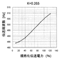
図13Aは、k=0.3の場合における実施例1についての伝送効率と伝送電力との関係を示すグラフである。図13Bは、図13Aの伝送効率を得るときの伝送周波数と伝送電力との関係を示すグラフである。図における□はfs/fp=0.922の場合、△はfs/fp=0.894の場合を示す。いずれのfs/fpも、式2の関数F(k)で示される基準値よりも小さい。図13Aからわかるように、規格化された伝送電力が約40〜50%で、伝送効率が局所的に低下するDipが観察される。Dip率は、fs/fp=0.894の場合、3%を超えている。伝送周波数は、図13Bに示されるように変化している。この変化のモードは、図9Bに示されるパターンを有している。 FIG. 13A is a graph showing the relationship between transmission efficiency and transmission power for Example 1 when k = 0.3. FIG. 13B is a graph showing the relationship between transmission frequency and transmission power when the transmission efficiency of FIG. 13A is obtained. In the figure, □ indicates the case where fs / fp = 0.922, and Δ indicates the case where fs / fp = 0.894. Either fs / fp is smaller than the reference value indicated by the function F (k) in Equation 2. As can be seen from FIG. 13A, Dip is observed where the normalized transmission power is about 40 to 50% and the transmission efficiency is locally reduced. The Dip rate exceeds 3% when fs / fp = 0.894. The transmission frequency changes as shown in FIG. 13B. This mode of change has the pattern shown in FIG. 9B.
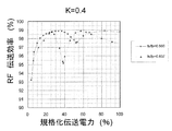
(実施例4)結合係数0.4の場合
(fs/fp=0.866の場合)
送電アンテナのインダクタンス:47.99uH
送電アンテナのキャパシタンス:11.32nF
送電アンテナの共振周波数fs:184.7kHz
受電アンテナのインダクタンス:41.56uH
受電アンテナのキャパシタンス:9.81nF
受電アンテナの共振周波数fp:246.4kHz
送受電アンテナ対の共振周波数fL:194.9kHz
送受電アンテナ対の共振周波数fH:300.1kHz
(fs/fp=0.837の場合)
送電アンテナのインダクタンス:43.02uH
送電アンテナのキャパシタンス:10.15nF
送電アンテナの共振周波数fs:229.9kHz
受電アンテナのインダクタンス:35.99uH
受電アンテナのキャパシタンス:8.49nF
受電アンテナの共振周波数fp:328.4kHz
送受電アンテナ対の共振周波数fL:220.1kHz
送受電アンテナ対の共振周波数fH:340.8kHz(Example 4) When the coupling coefficient is 0.4 (when fs / fp = 0.866)
Inductance of power transmission antenna: 47.9uH
Transmission antenna capacitance: 11.32 nF
Resonant frequency fs of power transmission antenna: 184.7 kHz
Receiving antenna inductance: 41.56 uH
Capacitance of the receiving antenna: 9.81 nF
Receiving antenna resonance frequency fp: 246.4 kHz
Resonant frequency fL of power transmitting / receiving antenna pair: 194.9 kHz
Resonant frequency fH of power transmitting / receiving antenna pair: 300.1 kHz
(When fs / fp = 0.737)
Inductance of power transmission antenna: 43.02uH
Capacitance of power transmission antenna: 10.15nF
Resonant frequency fs of power transmission antenna: 229.9 kHz
Inductance of power receiving antenna: 35.99uH
Receiving antenna capacitance: 8.49nF
Receiving antenna resonance frequency fp: 328.4 kHz
Resonant frequency fL of power transmitting / receiving antenna pair: 220.1 kHz
Resonant frequency fH of power transmitting / receiving antenna pair: 340.8 kHz
図14Aは、k=0.4の場合における実施例1についての伝送効率と伝送電力との関係を示すグラフである。図14Bは、図14Aの伝送効率を得るときの伝送周波数と伝送電力との関係を示すグラフである。図における□はfs/fp=0.866の場合、△はfs/fp=0.837の場合を示す。いずれのfs/fpも、式2の関数F(k)で示される基準値よりも小さい。図14Aからわかるように、規格化された伝送電力が約30〜60%で伝送効率が局所的に低下するDipが観察される。Dip率は、fs/fp=0.894の場合、3%を超えている。伝送周波数は、図14Bに示されるように変化している。この変化のモードは、図9Bに示されるパターンを有している。 FIG. 14A is a graph showing the relationship between transmission efficiency and transmission power for Example 1 when k = 0.4. FIG. 14B is a graph showing the relationship between transmission frequency and transmission power when the transmission efficiency of FIG. 14A is obtained. In the figure, □ indicates the case where fs / fp = 0.866, and Δ indicates the case where fs / fp = 0.737. Either fs / fp is smaller than the reference value indicated by the function F (k) in Equation 2. As can be seen from FIG. 14A, Dip is observed in which the transmission efficiency is locally reduced when the normalized transmission power is about 30 to 60%. The Dip rate exceeds 3% when fs / fp = 0.894. The transmission frequency changes as shown in FIG. 14B. This mode of change has the pattern shown in FIG. 9B.
(実施例5)結合係数0.5の場合
(fs/fp=0.854の場合)
送電アンテナのインダクタンス:15.86uH
送電アンテナのキャパシタンス:33.94nF
送電アンテナの共振周波数fs:186.5kHz
受電アンテナのインダクタンス:63.02uH
受電アンテナのキャパシタンス:6.23nF
受電アンテナの共振周波数fp:255.5kHz
送受電アンテナ対の共振周波数fL:190.2kHz
送受電アンテナ対の共振周波数fH:331.2kHz
(fs/fp=0.837の場合)
送電アンテナのインダクタンス:15.86uH
送電アンテナのキャパシタンス:33.94nF
送電アンテナの共振周波数fs:186.5kHz
受電アンテナのインダクタンス:61.71uH
受電アンテナのキャパシタンス:6.11nF
受電アンテナの共振周波数fp:266.5kHz
送受電アンテナ対の共振周波数fL:195.3kHz
送受電アンテナ対の共振周波数fH:335.1kHz(Example 5) When the coupling coefficient is 0.5 (when fs / fp = 0.854)
Inductance of power transmission antenna: 15.86uH
Transmission antenna capacitance: 33.94nF
Resonant frequency fs of power transmission antenna: 186.5 kHz
Inductance of power receiving antenna: 63.02uH
Capacitance of receiving antenna: 6.23 nF
Receiving antenna resonance frequency fp: 255.5 kHz
Resonant frequency fL of power transmitting / receiving antenna pair: 190.2 kHz
Resonant frequency fH of power transmitting / receiving antenna pair: 331.2 kHz
(When fs / fp = 0.737)
Inductance of power transmission antenna: 15.86uH
Transmission antenna capacitance: 33.94nF
Resonant frequency fs of power transmission antenna: 186.5 kHz
Inductance of power receiving antenna: 61.71 uH
Capacitance of the receiving antenna: 6.11 nF
Receiving antenna resonance frequency fp: 266.5 kHz
Resonant frequency fL of power transmitting / receiving antenna pair: 195.3 kHz
Resonant frequency fH of power transmitting / receiving antenna pair: 335.1 kHz
図15Aは、k=0.5の場合における実施例1についての伝送効率と伝送電力との関係を示すグラフである。図15Bは、図15Aの伝送効率を得るときの伝送周波数と伝送電力との関係を示すグラフである。図における□はfs/fp=0.854の場合、△はfs/fp=0.837の場合を示す。いずれのfs/fpも、式2の関数F(k)で示される基準値よりも小さい。図15Aからわかるように、いずれの場合も、Dipはほとんど観察されない。伝送周波数は、図15Bに示されるように変化している。この変化のモードは、図9Bに示されるパターンを有している。 FIG. 15A is a graph showing the relationship between transmission efficiency and transmission power for Example 1 when k = 0.5. FIG. 15B is a graph showing the relationship between transmission frequency and transmission power when the transmission efficiency of FIG. 15A is obtained. In the figure, □ indicates the case where fs / fp = 0.854, and Δ indicates the case where fs / fp = 0.737. Either fs / fp is smaller than the reference value indicated by the function F (k) in Equation 2. As can be seen from FIG. 15A, almost no Dip is observed in either case. The transmission frequency changes as shown in FIG. 15B. This mode of change has the pattern shown in FIG. 9B.
図16は、k=0.3、fs/fp=0.922の場合において、伝送周波数の制御を行うときの伝送効率(with f-ctrl)と、伝送周波数の制御を行わないときの伝送効率(w/o f-ctrl)とを示すグラフである。伝送周波数の制御を行わない場合、伝送電力が相対的に大きな領域で伝送効率の著しい低下がみられる。しかし、伝送周波数の制御を行って図9Bに示すように変化させると、大電力伝送時の伝送効率を著しく改善できることがわかる。 FIG. 16 shows the transmission efficiency when the transmission frequency is controlled (with f-ctrl) and the transmission efficiency when the transmission frequency is not controlled when k = 0.3 and fs / fp = 0.922. It is a graph which shows (w / of f-ctrl). When the transmission frequency is not controlled, the transmission efficiency is remarkably lowered in a region where the transmission power is relatively large. However, it can be seen that if the transmission frequency is controlled and changed as shown in FIG. 9B, the transmission efficiency during high power transmission can be significantly improved.
(比較例1〜2)
実施例1では送電側アンテナと受電側アンテナの共振回路構成を非対称としたが、送受アンテナを対称な共振回路構成とした比較例1、2を作製した。比較例1では送受アンテナは共に直列共振回路、比較例2では送受アンテナは共に並列共振回路で構成した。実施例1と同様の検討を行い、定電圧動作時の各伝送電力での最大伝送効率と、最大伝送効率を実現する伝送周波数(ピーク周波数)とを導出した。ここでは、k=0.3、fs/fp=0.922に設定した。比較例1の伝送効率の伝送電力依存性を図17に示す。図17から明らかなように、比較例1の伝送効率は狭い範囲でのみ高い。また、伝送周波数を制御しても、伝送効率の改善は小さい。(Comparative Examples 1-2)
In Example 1, the resonance circuit configuration of the power transmission side antenna and the power reception side antenna is asymmetric, but Comparative Examples 1 and 2 in which the transmission and reception antennas are symmetrical resonance circuit configurations were produced. In Comparative Example 1, the transmitting and receiving antennas are both configured as a series resonant circuit, and in Comparative Example 2, both the transmitting and receiving antennas are configured as a parallel resonant circuit. The same examination as in Example 1 was performed, and the maximum transmission efficiency at each transmission power during the constant voltage operation and the transmission frequency (peak frequency) for realizing the maximum transmission efficiency were derived. Here, k = 0.3 and fs / fp = 0.922 were set. FIG. 17 shows the transmission power dependence of the transmission efficiency of Comparative Example 1. As is apparent from FIG. 17, the transmission efficiency of Comparative Example 1 is high only in a narrow range. Even if the transmission frequency is controlled, the improvement in transmission efficiency is small.
図18は、比較例1の伝送周波数と伝送電力との関係を示すグラフである。図18から明らかなように、比較例1の伝送周波数は、電力伝送領域が小電力側に向かうにしたがって、偶モード共振周波数302kHzを大きく超えた値になっており、本願発明の実施形態の周波数制御条件にも従っていなかった。同様に、送受アンテナのいずれも並列共振器から構成した比較例2の伝送効率を図19に示し、伝送周波数の伝送電力依存性を図20に示す。これらの図から明らかなように、比較例2でも本発明の実施形態の効果は発現しなかった。 FIG. 18 is a graph showing the relationship between the transmission frequency and the transmission power in Comparative Example 1. As is clear from FIG. 18, the transmission frequency of Comparative Example 1 is a value that greatly exceeds the even mode resonance frequency of 302 kHz as the power transmission region moves toward the low power side, and is the frequency of the embodiment of the present invention. The control conditions were not followed. Similarly, FIG. 19 shows the transmission efficiency of Comparative Example 2 in which both of the transmitting and receiving antennas are constituted by parallel resonators, and FIG. 20 shows the transmission power dependence of the transmission frequency. As is clear from these figures, even in Comparative Example 2, the effect of the embodiment of the present invention did not appear.
(比較例3)
実施例1では送受アンテナに計測用の高周波入出力端子を直結することにより、外部回路から送受アンテナへの信号給電を行っていた。比較例3では、外部回路から送受アンテナへの信号給電を、電磁誘導原理を用いて行った。具体的には、それぞれ送受アンテナから3mm離間して対向した直径20cm、巻き数6の非共振コイルを用い、外部回路から非共振コイルを励振し、非共振コイルから非接触で送受アンテナを励振した。実施例1と同様の検討を行い、定電圧動作時の各伝送電力での最大伝送効率と最大伝送効率を実現する伝送周波数を導出した。比較例3、実施例1の伝送効率の伝送電力依存性を図21に示す。図21からわかるように、比較例3では、小電力伝送領域に向かうにつれ生じる最大伝送効率の劣化が激しい。また、図22より明らかなように、比較例3の伝送周波数は、伝送電力の増大に従い単調に増大しており、本願発明の実施形態の周波数制御条件にも従っていなかった。これは、比較例3の構成が、奇モード共振のみを利用して伝送電力の変動に対応していることを示しており、偶奇共振モードを最大限利用する本願発明の実施形態の動作原理とは異なることが実証された。(Comparative Example 3)
In the first embodiment, a signal is fed from an external circuit to the transmission / reception antenna by directly connecting a measurement high-frequency input / output terminal to the transmission / reception antenna. In Comparative Example 3, signal feeding from the external circuit to the transmission / reception antenna was performed using the electromagnetic induction principle. Specifically, a non-resonant coil having a diameter of 20 cm and a winding number of 6 facing each other 3 mm away from the transmitting and receiving antennas was used, the non-resonant coil was excited from an external circuit, and the transmitting and receiving antennas were excited from the non-resonant coil in a non-contact manner. . The same examination as in Example 1 was performed, and the maximum transmission efficiency at each transmission power during the constant voltage operation and the transmission frequency that realizes the maximum transmission efficiency were derived. FIG. 21 shows the transmission power dependence of the transmission efficiency of Comparative Example 3 and Example 1. As can be seen from FIG. 21, in Comparative Example 3, the maximum transmission efficiency is severely deteriorated toward the low power transmission region. Further, as is apparent from FIG. 22, the transmission frequency of Comparative Example 3 monotonously increases as the transmission power increases, and does not follow the frequency control conditions of the embodiment of the present invention. This indicates that the configuration of Comparative Example 3 uses only odd-mode resonance to cope with fluctuations in transmission power, and the operation principle of the embodiment of the present invention that uses the even-odd resonance mode to the maximum Proved to be different.
(比較例4、5)
比較例4と5では、送受アンテナの一方に対しては直結型の給電を行い、他方には電磁誘導給電を行った。直結型の給電については実施例1と同様の条件とした。また、電磁誘導給電については比較例3と同様の条件とした。表1に、実施例1と比較例1〜5の回路構成比較を示す。(Comparative Examples 4 and 5)
In Comparative Examples 4 and 5, direct connection type power supply was performed on one of the transmission and reception antennas, and electromagnetic induction power supply was performed on the other. The direct connection type power feeding was performed under the same conditions as in Example 1. Further, the electromagnetic induction power feeding was performed under the same conditions as in Comparative Example 3. Table 1 shows a circuit configuration comparison between Example 1 and Comparative Examples 1 to 5.
比較例4、5についても、実施例1と同様の検討を行い、定電圧動作時の各伝送電力での最大伝送効率と最大伝送効率を実現する伝送周波数を導出した。図23より明らかなように、比較例4の伝送周波数は、電力伝送領域が小電力側に向かうにしたがって、上昇する傾向を示しており、本願発明の周波数制御条件にも従っていなかった。同様に、比較例5の伝送周波数の伝送電力依存性を示した図24から明らかなように、比較例5も本発明の実施形態の周波数制御条件に従っていなかった。 For Comparative Examples 4 and 5, the same study as in Example 1 was performed, and the maximum transmission efficiency and the transmission frequency for realizing the maximum transmission efficiency at each transmission power during the constant voltage operation were derived. As is clear from FIG. 23, the transmission frequency of Comparative Example 4 shows a tendency to increase as the power transmission region moves toward the low power side, and does not follow the frequency control condition of the present invention. Similarly, as is clear from FIG. 24 showing the transmission power dependence of the transmission frequency of Comparative Example 5, Comparative Example 5 also did not comply with the frequency control conditions of the embodiment of the present invention.

本願発明の無線電力伝送装置の実施形態は、一定電圧を供給する電源回路からエネルギー供給を受けて動作することが可能な、AV機器白物家電などのさまざまな機器への給電システムに適用できる。AV機器は、例えばテレビを含み、白物家電は、例えば洗濯機、冷蔵庫、およびエアコンを含む。 The embodiment of the wireless power transmission device of the present invention can be applied to a power supply system to various devices such as AV appliance white goods that can operate by receiving energy supply from a power supply circuit that supplies a constant voltage. AV equipment includes, for example, a television, and white goods include, for example, a washing machine, a refrigerator, and an air conditioner.
また、本発明の無線電力伝送装置の実施形態は、充電池を用いる電子機器、電動バイク、電動アシスト自転車、電気自動車への充電システムとして適用することも可能である。これは、リチウムイオン電池などの充電池への充電制御の一つとして、定電圧での充電制御が要求される場合があるからである。また、一定電圧で駆動するモータを伴う全ての電子機器に対しても本願発明のシステムは適用しうる。 Further, the embodiment of the wireless power transmission device of the present invention can be applied as a charging system for an electronic device using a rechargeable battery, an electric motorcycle, an electric assist bicycle, and an electric vehicle. This is because charging control at a constant voltage may be required as one of charging control for a rechargeable battery such as a lithium ion battery. In addition, the system of the present invention can be applied to all electronic devices with a motor driven at a constant voltage.
また、太陽光発電システムにおいて太陽電池セルへの照射太陽光強度(照度)が変化した場合、最大電力点(最大電力を発電するための電流、電圧値)は、電流が照度にほぼ比例し、電圧はほぼ一定となることが知られている。よって、本願発明の無線電力伝送装置の実施形態は、太陽光発電装置が発電する電力を集電するシステムにも適用できる。 Moreover, when the irradiation solar light intensity (illuminance) to the solar battery cell changes in the solar power generation system, the maximum power point (current and voltage value for generating the maximum power) is substantially proportional to the illuminance, It is known that the voltage is almost constant. Therefore, the embodiment of the wireless power transmission device of the present invention can be applied to a system that collects the power generated by the solar power generation device.
100 伝送周波数制御部
102 発電部
103 発振器
107 送電アンテナ(送電側の共振器)
107a 第1インダクタ
107b 第1キャパシタ
109 受電アンテナ(受電側の共振器)
109a 第2インダクタ
109b 第2キャパシタ
111 負荷
161 周波数変換回路
200 直列共振回路
300 並列共振回路DESCRIPTION OF
107a
109a
Claims (14)
前記一対のアンテナのうち、高周波電力を送る側のアンテナに接続された発振器と、
前記一対のアンテナ間を伝送される電力の大きさに応じて伝送周波数を制御する制御部と、
を備え、
前記一対のアンテナ間の結合係数をkとするとき、
fs/fp<−0.6074×k2+0.0466×k+0.9955の関係を満たすようにfsおよびfpが設定されている、無線電力伝送装置。 A pair of antennas capable of transmitting power in a contactless manner by resonant magnetic field coupling, one of which is a series resonant circuit having a resonant frequency of fs and the other of which is a parallel resonant circuit having a resonant frequency of fp; ,
Of the pair of antennas, an oscillator connected to an antenna on the side that transmits high-frequency power; and
A control unit that controls a transmission frequency according to the magnitude of power transmitted between the pair of antennas;
With
When the coupling coefficient between the pair of antennas is k,
A wireless power transmission apparatus in which fs and fp are set so as to satisfy a relationship of fs / fp <−0.6074 × k 2 + 0.0466 × k + 0.9955.
前記電力が基準値P1よりも高いとき、前記伝送周波数を第1周波数範囲内の値に設定し、前記電力が前記基準値P1よりも低いときは、前記伝送周波数を、前記第1周波数範囲よりも高い第2周波数範囲内の値に設定する、請求項1に記載の無線電力伝送装置。 The controller is
When the power is higher than the reference value P1, the transmission frequency is set to a value within the first frequency range, and when the power is lower than the reference value P1, the transmission frequency is set to be lower than the first frequency range. The wireless power transmission device according to claim 1, wherein the wireless power transmission device is set to a value within a higher second frequency range.
前記伝送電力の少なくとも1つの値において、伝送周波数の増加または減少に伴って伝送効率が上昇するか低下するかを評価し、前記評価結果に基づいて伝送周波数の制御パターンを決定する、請求項1から8のいずれかに記載の無線電力伝送装置。 The controller is
The at least one value of the transmission power is evaluated as to whether the transmission efficiency increases or decreases as the transmission frequency increases or decreases, and a transmission frequency control pattern is determined based on the evaluation result. The wireless power transmission device according to any one of 1 to 8.
前記制御部は、無線電力伝送装置の設置後に、fs/fpの値を変化させる、請求項1から9のいずれかに記載の無線電力伝送装置。 The pair of antennas has a resonance frequency adjusting function for changing at least one of fs and fp,
The wireless power transmission device according to claim 1, wherein the control unit changes a value of fs / fp after the wireless power transmission device is installed.
前記一対のアンテナのうち高周波電力を送る側のアンテナと、
前記アンテナに接続された発振器と、
を備える、送電装置。 A power transmission device used in the wireless power transmission device according to any one of claims 1 to 11,
Of the pair of antennas, the antenna on the side that sends high-frequency power;
An oscillator connected to the antenna;
A power transmission device.
前記一対のアンテナのうち高周波電力を受け取る側のアンテナを備える、受電装置。 A power receiving device used in the wireless power transmission device according to any one of claims 1 to 11,
A power receiving device including an antenna on a side receiving high-frequency power among the pair of antennas.
前記一対のアンテナ間を伝送される電力の大きさに応じて伝送周波数を制御する、制御装置。
A control device used in the wireless power transmission device according to claim 1,
A control device that controls a transmission frequency according to the magnitude of power transmitted between the pair of antennas.
Applications Claiming Priority (3)
| Application Number | Priority Date | Filing Date | Title |
|---|---|---|---|
| US201161564370P | 2011-11-29 | 2011-11-29 | |
| US61/564,370 | 2011-11-29 | ||
| PCT/JP2012/007619 WO2013080530A1 (en) | 2011-11-29 | 2012-11-28 | Wireless power transmission device |
Publications (2)
| Publication Number | Publication Date |
|---|---|
| JPWO2013080530A1 JPWO2013080530A1 (en) | 2015-04-27 |
| JP6108310B2 true JP6108310B2 (en) | 2017-04-05 |
Family
ID=48466175
Family Applications (1)
| Application Number | Title | Priority Date | Filing Date |
|---|---|---|---|
| JP2013520657A Active JP6108310B2 (en) | 2011-11-29 | 2012-11-28 | Wireless power transmission device |
Country Status (5)
| Country | Link |
|---|---|
| US (1) | US9197101B2 (en) |
| EP (1) | EP2787601B1 (en) |
| JP (1) | JP6108310B2 (en) |
| CN (1) | CN103354970B (en) |
| WO (1) | WO2013080530A1 (en) |
Families Citing this family (6)
| Publication number | Priority date | Publication date | Assignee | Title |
|---|---|---|---|---|
| US9768643B2 (en) * | 2012-11-02 | 2017-09-19 | Panasonic Intellectual Property Management Co., Ltd. | Wireless power transmission system capable of continuing power transmission while suppressing heatup of foreign objects |
| KR102004541B1 (en) * | 2012-12-31 | 2019-07-26 | 지이 하이브리드 테크놀로지스, 엘엘씨 | Method for controlling wireless power transmission in resonat wireless power transmission system, wireless power transmitting apparatus using the same, and wireless power receiving apparatus using the same |
| CN105576715B (en) * | 2014-11-01 | 2018-12-04 | 松下知识产权经营株式会社 | Power transmission device, vehicle and Wireless power transmission system equipped with power transmission device |
| CN105576847B (en) * | 2014-11-01 | 2018-05-11 | 松下知识产权经营株式会社 | Power transmission device, the vehicle and Wireless power transmission system for being equipped with power transmission device |
| US20170085113A1 (en) * | 2015-09-22 | 2017-03-23 | Intel Corporation | Constant current radio frequency generator for a wireless charging system |
| CN110378007A (en) * | 2019-07-12 | 2019-10-25 | 天津大学 | A kind of circuit analysis method of multiple coupling LC resonance device |
Family Cites Families (10)
| Publication number | Priority date | Publication date | Assignee | Title |
|---|---|---|---|---|
| JP2002152997A (en) | 2000-11-09 | 2002-05-24 | Nippon Baruufu Kk | High-frequency remote power supply |
| US7825543B2 (en) | 2005-07-12 | 2010-11-02 | Massachusetts Institute Of Technology | Wireless energy transfer |
| DE112006002299T5 (en) * | 2005-09-01 | 2008-06-26 | National University Corporation Saitama University | Contact-free power supply device |
| WO2009089253A1 (en) | 2008-01-07 | 2009-07-16 | Access Business Group International Llc | Inductive power supply with duty cycle control |
| JP2010136464A (en) | 2008-12-02 | 2010-06-17 | Casio Computer Co Ltd | Power transmitter and power transmission method |
| JP4815499B2 (en) | 2009-02-27 | 2011-11-16 | 東光株式会社 | Non-contact power transmission circuit |
| WO2011019088A2 (en) | 2009-08-13 | 2011-02-17 | Panasonic Corporation | Wireless power transmission unit and power generator and power generation system with the wireless power unit |
| JP5016069B2 (en) | 2010-01-12 | 2012-09-05 | トヨタ自動車株式会社 | Power transmission system and vehicle power supply device |
| US9620995B2 (en) | 2011-04-26 | 2017-04-11 | Panasonic Intellectual Property Management Co., Ltd. | Wireless power transmission system |
| US9224533B2 (en) | 2011-11-29 | 2015-12-29 | Panasonic Intellectual Property Management Co., Ltd. | Wireless electric power transmission apparatus |
-
2012
- 2012-11-27 US US13/686,104 patent/US9197101B2/en active Active
- 2012-11-28 EP EP12852692.8A patent/EP2787601B1/en active Active
- 2012-11-28 CN CN201280003796.5A patent/CN103354970B/en active Active
- 2012-11-28 WO PCT/JP2012/007619 patent/WO2013080530A1/en active Application Filing
- 2012-11-28 JP JP2013520657A patent/JP6108310B2/en active Active
Also Published As
| Publication number | Publication date |
|---|---|
| US20130134796A1 (en) | 2013-05-30 |
| JPWO2013080530A1 (en) | 2015-04-27 |
| EP2787601B1 (en) | 2020-09-30 |
| EP2787601A1 (en) | 2014-10-08 |
| US9197101B2 (en) | 2015-11-24 |
| WO2013080530A1 (en) | 2013-06-06 |
| CN103354970A (en) | 2013-10-16 |
| EP2787601A4 (en) | 2015-11-11 |
| CN103354970B (en) | 2018-01-23 |
Similar Documents
| Publication | Publication Date | Title |
|---|---|---|
| JP6172607B2 (en) | Wireless power transmission device | |
| JP5172050B2 (en) | Wireless power transmission device | |
| US10186909B2 (en) | Wireless power transfer system for wirelessly transferring electric power in noncontact manner by utilizing resonant magnetic field coupling | |
| JP5934934B2 (en) | Wireless power transmission system | |
| JP6108310B2 (en) | Wireless power transmission device | |
| JP6094820B2 (en) | Wireless power transmission device | |
| JP2012191697A (en) | Non-contact power transmission apparatus |
Legal Events
| Date | Code | Title | Description |
|---|---|---|---|
| A621 | Written request for application examination |
Free format text: JAPANESE INTERMEDIATE CODE: A621 Effective date: 20150721 |
|
| A131 | Notification of reasons for refusal |
Free format text: JAPANESE INTERMEDIATE CODE: A131 Effective date: 20160913 |
|
| A521 | Request for written amendment filed |
Free format text: JAPANESE INTERMEDIATE CODE: A523 Effective date: 20161021 |
|
| TRDD | Decision of grant or rejection written | ||
| A01 | Written decision to grant a patent or to grant a registration (utility model) |
Free format text: JAPANESE INTERMEDIATE CODE: A01 Effective date: 20170214 |
|
| A61 | First payment of annual fees (during grant procedure) |
Free format text: JAPANESE INTERMEDIATE CODE: A61 Effective date: 20170227 |
|
| R151 | Written notification of patent or utility model registration |
Ref document number: 6108310 Country of ref document: JP Free format text: JAPANESE INTERMEDIATE CODE: R151 |