JP6107944B2 - Portable information processing apparatus, information processing system, and information processing method - Google Patents
Portable information processing apparatus, information processing system, and information processing method Download PDFInfo
- Publication number
- JP6107944B2 JP6107944B2 JP2015516802A JP2015516802A JP6107944B2 JP 6107944 B2 JP6107944 B2 JP 6107944B2 JP 2015516802 A JP2015516802 A JP 2015516802A JP 2015516802 A JP2015516802 A JP 2015516802A JP 6107944 B2 JP6107944 B2 JP 6107944B2
- Authority
- JP
- Japan
- Prior art keywords
- event
- transition
- sensing
- unit
- information processing
- Prior art date
- Legal status (The legal status is an assumption and is not a legal conclusion. Google has not performed a legal analysis and makes no representation as to the accuracy of the status listed.)
- Active
Links
Images


Classifications
-
- H—ELECTRICITY
- H04—ELECTRIC COMMUNICATION TECHNIQUE
- H04W—WIRELESS COMMUNICATION NETWORKS
- H04W4/00—Services specially adapted for wireless communication networks; Facilities therefor
- H04W4/02—Services making use of location information
- H04W4/029—Location-based management or tracking services
-
- H—ELECTRICITY
- H04—ELECTRIC COMMUNICATION TECHNIQUE
- H04W—WIRELESS COMMUNICATION NETWORKS
- H04W4/00—Services specially adapted for wireless communication networks; Facilities therefor
- H04W4/30—Services specially adapted for particular environments, situations or purposes
- H04W4/33—Services specially adapted for particular environments, situations or purposes for indoor environments, e.g. buildings
-
- H—ELECTRICITY
- H04—ELECTRIC COMMUNICATION TECHNIQUE
- H04W—WIRELESS COMMUNICATION NETWORKS
- H04W52/00—Power management, e.g. TPC [Transmission Power Control], power saving or power classes
- H04W52/02—Power saving arrangements
- H04W52/0209—Power saving arrangements in terminal devices
- H04W52/0251—Power saving arrangements in terminal devices using monitoring of local events, e.g. events related to user activity
- H04W52/0258—Power saving arrangements in terminal devices using monitoring of local events, e.g. events related to user activity controlling an operation mode according to history or models of usage information, e.g. activity schedule or time of day
-
- H—ELECTRICITY
- H04—ELECTRIC COMMUNICATION TECHNIQUE
- H04W—WIRELESS COMMUNICATION NETWORKS
- H04W88/00—Devices specially adapted for wireless communication networks, e.g. terminals, base stations or access point devices
- H04W88/02—Terminal devices
- H04W88/06—Terminal devices adapted for operation in multiple networks or having at least two operational modes, e.g. multi-mode terminals
-
- Y—GENERAL TAGGING OF NEW TECHNOLOGICAL DEVELOPMENTS; GENERAL TAGGING OF CROSS-SECTIONAL TECHNOLOGIES SPANNING OVER SEVERAL SECTIONS OF THE IPC; TECHNICAL SUBJECTS COVERED BY FORMER USPC CROSS-REFERENCE ART COLLECTIONS [XRACs] AND DIGESTS
- Y02—TECHNOLOGIES OR APPLICATIONS FOR MITIGATION OR ADAPTATION AGAINST CLIMATE CHANGE
- Y02D—CLIMATE CHANGE MITIGATION TECHNOLOGIES IN INFORMATION AND COMMUNICATION TECHNOLOGIES [ICT], I.E. INFORMATION AND COMMUNICATION TECHNOLOGIES AIMING AT THE REDUCTION OF THEIR OWN ENERGY USE
- Y02D30/00—Reducing energy consumption in communication networks
- Y02D30/70—Reducing energy consumption in communication networks in wireless communication networks
Landscapes
- Engineering & Computer Science (AREA)
- Computer Networks & Wireless Communication (AREA)
- Signal Processing (AREA)
- Telephone Function (AREA)
- Mobile Radio Communication Systems (AREA)
Description
本発明は、センシング部を制御する携帯型情報処理装置,情報処理システム,及び情報処理方法に関する。 The present invention relates to a portable information processing device, an information processing system, and an information processing method for controlling a sensing unit.
図1は、場所判定センシング部の一例を示す図である。場所判定センシング部には、大別して、絶対座標を取得するもの,設置機器の検出範囲内にいることを取得するもの,設置機器の設置場所の通過を取得するもの(通過型)がある。 FIG. 1 is a diagram illustrating an example of a place determination sensing unit. The location determination sensing unit is roughly classified into one that acquires absolute coordinates, one that acquires that it is within the detection range of the installed device, and one that acquires passage through the installation location of the installed device (passing type).
絶対座標を取得するセンシング部には、例えば、GPS受信機がある。GPS受信機は、GPS衛星からの信号を受信し、現在位置する緯度及び緯度を測定し、地図情報と比較して、場所の進入及び退出を検出する。緯度及び経度は絶対座標ともいう。 A sensing unit that acquires absolute coordinates includes, for example, a GPS receiver. The GPS receiver receives a signal from a GPS satellite, measures the latitude and latitude at which it is currently located, and compares it with map information to detect entry and exit of a place. Latitude and longitude are also called absolute coordinates.
設置機器の検出範囲内にいることを取得するセンシング部には、例えば、Wi−Fi(Wireless Fidelity)機器,Bluetooth(登録商標)機器,マイクロフォンがあ
る。Wi−Fi機器は、例えば、受信電波から取得されるWi−Fiアクセスポイントの識別情報であるSSID(Service Set Identifier)と、電波強度を示すRSSI(Received Signal Strength Indication)情報とから、該SSIDのアクセスポイントの検出
範囲への進入又は退出を検出する。Bluetooth機器は、例えば、受信電波から設置されたBluetooth(登録商標)機器のIDを検出することによって、該IDのBluetooth機器の検出範囲の進入又は退出を検出する。マイクロフォンは、例えば、収音した音波信号の中の、可聴範囲外の音波信号からIDを検出することによって、該IDの設置機器の検出範囲の進入又は退出を検出する。
Examples of the sensing unit that acquires that the device is within the detection range of the installed device include a Wi-Fi (Wireless Fidelity) device, a Bluetooth (registered trademark) device, and a microphone. The Wi-Fi device, for example, from the SSID (Service Set Identifier) that is identification information of the Wi-Fi access point acquired from the received radio wave and the RSSI (Received Signal Strength Indication) information indicating the radio wave intensity, Detect entry or exit of access point detection range. For example, the Bluetooth device detects the ID of the Bluetooth (registered trademark) device installed from the received radio wave, thereby detecting the entry or exit of the detection range of the Bluetooth device with the ID. For example, the microphone detects the ID from the sound wave signal outside the audible range in the collected sound wave signal, thereby detecting the entry or exit of the detection range of the installation device of the ID.
設置機器の設置場所の通過を取得するセンシング部には、例えば、NFC(Near Field Communication)機器,カメラがある。NFC機器には、例えば、NFCリーダ,ICカードがある。例えば、NFC機器としてのICカードを備える携帯端末は、NFCリーダへのタッチを検出することで、該NFCリーダの設置場所の通過を検出する。カメラは、例えば、所定の位置に設置されているQRコード(登録商標)等のマーカを撮像画像から認識することによって、該所定の位置の通過を検出する。 For example, there are NFC (Near Field Communication) devices and cameras in the sensing unit that acquires the passage of the installed device through the installation location. NFC devices include, for example, NFC readers and IC cards. For example, a portable terminal equipped with an IC card as an NFC device detects a touch on the NFC reader, thereby detecting passage of the NFC reader. For example, the camera detects a passage of the predetermined position by recognizing a marker such as a QR code (registered trademark) installed at the predetermined position from the captured image.
しかしながら、複数のセンシング部を常時動作させていると、携帯端末の消費電力が大きくなるという問題があった。 However, when a plurality of sensing units are always operated, there is a problem that power consumption of the mobile terminal increases.
本発明の一態様は、複数のセンシング部による消費電力を低減することが可能な携帯型情報処理装置,情報処理システム,及び情報処理方法を提供することを目的とする。 An object of one embodiment of the present invention is to provide a portable information processing device, an information processing system, and an information processing method capable of reducing power consumption by a plurality of sensing units.
本発明の態様の一つは、
携帯型情報処理装置の現在位置を示す場所情報に変換可能な情報を取得し、該情報から変換により得られる前記場所情報に関して発生するイベントを検出する複数のセンシング部と、
前記複数のセンシング部によって取得済みのイベント間の遷移の順序と前記遷移の間の経過時間との関係を示すイベント遷移情報を記憶する記憶部と、
前記複数のセンシング部のいずれかによって検出された最新のイベントを現在のイベントとして求め、前記イベント遷移情報中で前記現在のイベントに対応するイベントから遷移する遷移先のイベントへの遷移時間と、前記現在のイベントが検出された時からの経過時間との関係から、前記イベント遷移情報中の前記遷移先のイベントを検出したセンシング部の動作状態を制御する制御部と、
を備える携帯型情報処理装置である。One aspect of the present invention is:
A plurality of sensing units for acquiring information that can be converted into place information indicating a current position of the portable information processing device, and detecting an event that occurs with respect to the place information obtained by conversion from the information;
A storage unit for storing event transition information indicating a relationship between an order of transition between events acquired by the plurality of sensing units and an elapsed time between the transitions;
The latest event detected by any of the plurality of sensing units is determined as a current event, the transition time from the event corresponding to the current event in the event transition information to the transition destination event, and From the relationship with the elapsed time from the time when the current event is detected, a control unit that controls the operating state of the sensing unit that has detected the transition destination event in the event transition information;
A portable information processing apparatus.
本発明の他の態様の一つは、上述した携帯型情報処理装置が実行する情報処理方法である。また、本発明の他の態様は、コンピュータを上述した携帯型情報処理装置として機能させる情報処理プログラム、及び当該プログラムを記録したコンピュータ読み取り可能な記録媒体を含むことができる。コンピュータ等が読み取り可能な記録媒体には、データやプログラム等の情報を電気的、磁気的、光学的、機械的、または化学的作用によって蓄積し、コンピュータ等から読み取ることができる記録媒体をいう。 Another aspect of the present invention is an information processing method executed by the above-described portable information processing apparatus. Another aspect of the present invention can include an information processing program that causes a computer to function as the above-described portable information processing apparatus, and a computer-readable recording medium that records the program. The computer-readable recording medium refers to a recording medium in which information such as data and programs is accumulated by electrical, magnetic, optical, mechanical, or chemical action and can be read from the computer or the like.
開示の携帯型情報処理装置,情報処理システム,及び情報処理方法によれば、複数のセンシング部による消費電力を低減することができる。 According to the disclosed portable information processing apparatus, information processing system, and information processing method, power consumption by a plurality of sensing units can be reduced.
以下、図面に基づいて、本発明の実施の形態を説明する。以下の実施形態の構成は例示であり、本発明は実施形態の構成に限定されない。 Hereinafter, embodiments of the present invention will be described with reference to the drawings. The configuration of the following embodiment is an exemplification, and the present invention is not limited to the configuration of the embodiment.
<第1実施形態>
図2は、第1実施形態に係る携帯型情報処理装置の処理の一例を示す図である。第1実施形態では、携帯型情報処理装置は、複数の種別の異なるセンシング部を備える。例えば、携帯型情報処理装置は、センシング部として、GPS受信モジュール,NFCモジュール,Wi−Fiモジュール,マイクロフォン,カメラ,等を備える。<First Embodiment>
FIG. 2 is a diagram illustrating an example of processing of the portable information processing device according to the first embodiment. In the first embodiment, the portable information processing device includes a plurality of different types of sensing units. For example, the portable information processing device includes a GPS receiving module, an NFC module, a Wi-Fi module, a microphone, a camera, and the like as a sensing unit.
センシングとは、所定の手段から、例えば、GPS信号,所定の周波数の電波,所定の周波数の音波信号,所定のマーカ等を検知することである。所定の手段には、例えば、GPS衛星,Wi−Fiアクセスポイント,NFCリーダ,識別マーカ等がある。携帯型情報処理装置のセンシング部は、センシングを行うことによって、例えば、絶対座標,Wi−FiアクセスポイントのSSID,NFCリーダのID,識別マーカのID等を取得する。センシング部は、これらのセンシングから得られる情報に紐付けられた場所情報を保持しており、センシングによって、現在位置を示す場所情報を取得する。現在位置を示す場所情報は、例えば、地図上の公園,敷地等の領域,機器の検出範囲,設置場所等である。すなわち、第1実施形態において、センシングとは、現在位置を示す場所情報に変換可能な情報を所定の手段から取得すること、である。 Sensing is to detect, for example, a GPS signal, a radio wave with a predetermined frequency, a sound wave signal with a predetermined frequency, a predetermined marker, or the like from a predetermined means. Examples of the predetermined means include a GPS satellite, a Wi-Fi access point, an NFC reader, and an identification marker. The sensing unit of the portable information processing apparatus obtains, for example, absolute coordinates, Wi-Fi access point SSID, NFC reader ID, identification marker ID, and the like by sensing. The sensing unit holds location information associated with information obtained from the sensing, and acquires location information indicating the current position by sensing. The location information indicating the current position is, for example, a park, a site area, a device detection range, an installation location, or the like on a map. That is, in the first embodiment, sensing is to acquire information that can be converted into place information indicating the current position from a predetermined means.
センシング部は、センシングの検知状況に応じて、センシングによって得られる情報に紐付けられた場所情報に関するイベントの発生を検出する。また、場所情報に関するイベントとは、例えば、所定の場所、又は、領域、地理的範囲に対する進入(enter),退出(exit),又は存在(stay)である。第1実施形態では、イベントは、種別,場所,検出元のセンシング部の種別によって区別される。 The sensing unit detects an occurrence of an event related to location information linked to information obtained by sensing according to a sensing detection state. In addition, the event related to location information is, for example, an entry, an exit, or a stay for a predetermined location, area, or geographical range. In the first embodiment, events are distinguished by type, location, and type of sensing unit as a detection source.
なお、イベントは各センシング部によって検出されるため、センシング部の種別や仕様によって、検出されるイベントは異なる。例えば、絶対座標を取得するセンシング部及び設置機器の検出範囲内にいることを取得するセンシング部は、所定の場所の進入,退出,存在のイベントの種別を検出する。また、例えば、通過型のセンシング部では、所定の場所の通過、すなわち、所定の場所での存在のイベントを検出する。ただし、これに限られない。 Since the event is detected by each sensing unit, the detected event differs depending on the type and specification of the sensing unit. For example, a sensing unit that obtains absolute coordinates and a sensing unit that obtains being within the detection range of an installed device detect the types of events of entry, exit, and presence of a predetermined location. Further, for example, a passing type sensing unit detects an event of passing through a predetermined place, that is, an existence at a predetermined place. However, it is not limited to this.
また、イベントの種別の呼称は、進入(enter),退出(exit),又は存在(stay)に限られず、各センシング部によって異なる。例えば、図2に示される例では、通過型のセンシング部であるNFCは、NFC Bの設置場所の存在(stay)のイベントを、タッチイベントと称する。なお、イベントの種別の呼称は各センシング部によって異なるものの、第1実施形態では、イベントは、進入(enter),退出(exit),又は存在(stay)のいずれかの種別に分類されるものとする。 Also, the name of the event type is not limited to entry, exit, or stay, but varies depending on each sensing unit. For example, in the example shown in FIG. 2, NFC, which is a passing-type sensing unit, refers to a stay event of the installation location of NFC B as a touch event. In addition, although the name of the event type varies depending on each sensing unit, in the first embodiment, the event is classified as one of the types of entry (enter), exit (exit), or presence (stay). To do.
携帯型情報処理装置は、各センシング部によって検出されたイベントの履歴情報から生成されるイベント遷移情報を記憶する記憶部を保持する。イベント遷移情報は、各センシング部によって取得済みのイベント間の遷移の順序と、イベント間の遷移時間と、の関係を示す情報である。携帯型情報処理装置は、最新のイベントを現在のイベントとし、イベント遷移情報中で現在のイベントに対応するイベントから遷移する遷移先のイベントへの遷移時間と、最新のイベントの検出からの経過時間との関係から、遷移先のイベントを検出したセンシング部の動作状態を制御する。 The portable information processing apparatus holds a storage unit that stores event transition information generated from history information of events detected by each sensing unit. The event transition information is information indicating the relationship between the order of transition between events acquired by each sensing unit and the transition time between events. The portable information processing device uses the latest event as the current event, the transition time from the event corresponding to the current event in the event transition information to the transition destination event, and the elapsed time since the detection of the latest event From this relationship, the operating state of the sensing unit that detects the event at the transition destination is controlled.
より具体的には、携帯型情報処理装置は、最新のイベントを起点とするイベントの遷移を求める。第1実施形態では、該イベントの遷移は有向グラフを用いて表される。携帯型情報処理装置は、イベントをノード,イベントの遷移をアーク,イベントの発生間隔をアークの長さとし、最新のイベントを起点として有向グラフを作成する。 More specifically, the portable information processing device obtains event transitions starting from the latest event. In the first embodiment, the transition of the event is represented using a directed graph. The portable information processing apparatus creates a directed graph starting from the latest event, with the event as a node, the event transition as an arc, and the event occurrence interval as the arc length.
例えば、図2に示される例では、履歴データに、場所A enterイベント発生のt1時間後にNFC Bタッチイベント、及び、t2時間後に場所A exitイベントの発生の履歴が含まれる。すなわち、履歴データから、場所A enterイベント発生後のt1時間後にNFC Bタッチイベント、及び、t2時間後に場所A exitイベントの発生が予測される。 For example, in the example shown in FIG. 2, the history data includes an NFC B touch event after t1 time of the place A enter event occurrence, and a history of occurrence of the place A exit event after t2 time. That is, from the history data, it is predicted that an NFC B touch event will occur after time t1 after the occurrence of the place A enter event, and a place A exit event will occur after time t2.
したがって、最新イベントが場所A enterイベントである場合には、場所A enterイベント,NFC Bタッチイベント,場所A exitイベントは、それぞれ、起点ノード51,ノード52,ノード53と設定される。さらに、起点ノード51とノード52とは、起点ノード51からノード52に向かうt1の長さのアークで接続される。起点ノード51とノード53とは、起点ノード51からノード53に向かうt2の長さのアークで接続される。
Therefore, when the latest event is the location A enter event, the location A enter event, the NFC B touch event, and the location A exit event are set as the
さらに、履歴データからは、NFC Bタッチイベントの後に、場所A exitイベントと領域C enterイベントの発生が予測されるので、上述のように、有向グラフにノード53,54とアーク63,64とが追加される。このようにして、履歴データから有向グラフが作成される。
Furthermore, since the occurrence of the location A exit event and the area Center event is predicted from the history data after the NFC B touch event, the
携帯型情報処理装置は、最新のイベントの発生からの経過時間Tと、各ノードの起点ノードからのアークの長さの合計との関係から、各ノードのイベントを検出するセンシング部の動作状態を決定する。例えば、図2では、t2<t1とすると、起点ノード51からの経過時間Tが、起点ノード51とノード53とを接続するアーク62の長さt2以上になる場合に、携帯型情報処理装置はノード53を選択し、ノード53に対応するセンシング部をオンにする。さらにイベントの発生が検出されずに時間が経過した場合、経過時間Tが起点ノード51とノード52とを接続するアーク61の長さt1(>t2)以上になる場合に、携帯型情報処理装置は、ノード52とノード53とのそれぞれに対応するセンシング部をオンにする。
The portable information processing device determines the operating state of the sensing unit that detects the event of each node from the relationship between the elapsed time T from the occurrence of the latest event and the total arc length from the starting node of each node. decide. For example, in FIG. 2, when t2 <t1, the portable information processing device is used when the elapsed time T from the starting
すなわち、図2に示される例において、携帯型情報処理装置は、0<経過時間T<t2の間は全センシング部をオフにする。また、携帯型情報処理装置は、t2≦経過時間T<t1の間はノード53に対応するセンシング部をオン、それ以外のセンシング部をオフにする。また、携帯型情報処理装置は、t1≦経過時間T<t1+t4の間はノード53とノード52とに対応するセンシング部をオン、それ以外のセンシング部をオフにする。ただし、センシング部の動作状態の制御は、センシング部をオンまたはオフにすることに限られず、例えば、動作インターバルの制御も含まれる。
That is, in the example shown in FIG. 2, the portable information processing device turns off all the sensing units during 0 <elapsed time T <t2. The portable information processing device turns on the sensing unit corresponding to the
これによって、携帯型情報処理装置は、次に発生する可能性のあるイベントのセンシング部をオンにし、それ以外のセンシング部をオフにすることによって、並列に起動しているセンシング部の数を少なくし、消費電力を低減する。 As a result, the portable information processing device reduces the number of sensing units activated in parallel by turning on the sensing unit of an event that may occur next and turning off the other sensing units. And reduce power consumption.
なお、携帯型情報処理装置において、有向グラフは図2に示されるような形態で作成されるとは限らない。例えば、情報処理装置は、ノードとアークとをそれぞれ定義し、遷移の順でノードとアークとの識別情報を列挙することで有向グラフとして扱ってもよい。また、以降の説明においては、ノード、アーク、という文言を用いるが、携帯型情報処理装置においては、ノード、アークとして定義されておらずともよい。例えば、イベントは、イベントとして、アークは、遷移元のイベントから遷移先のイベントへの遷移として定義されてもよい。 In the portable information processing apparatus, the directed graph is not always created in the form as shown in FIG. For example, the information processing apparatus may define a node and an arc, and treat the identification information of the node and the arc in the order of transition as a directed graph. In the following description, the terms “node” and “arc” are used. However, in the portable information processing apparatus, the term “node” and “arc” may not be defined. For example, an event may be defined as an event, and an arc may be defined as a transition from a transition source event to a transition destination event.
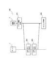
<システム構成>
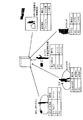
図3は、第1実施形態に係るセンシング制御システム100の構成とセンシング制御システム100における処理の流れとの一例を示す図である。センシング制御システム100は、サーバ1と複数の携帯端末2とを含む。ただし、図3では、便宜上、1台の携帯端末2が示される。携帯端末2は、「携帯型情報処理装置」の一例である。<System configuration>
FIG. 3 is a diagram illustrating an example of a configuration of the
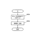
OP1では、各携帯端末2は、サーバ1にイベント履歴データを送信する。OP2では、サーバ1は、各携帯端末2から受信したイベント履歴データから、有向グラフデータを作成又は更新する。有向グラフデータの詳細については後述する。OP3では、サーバ1は、各携帯端末2に有向グラフデータを送信する。
In OP <b> 1, each
OP1−OP3の処理は、サーバ1及び各携帯端末2のそれぞれのタイミング、例えば、所定の周期で実行される。所定の周期は、例えば、1日に一回等の日単位、1週間に1回等の週単位、1カ月に1回等の月単位であり、システム管理者によって設定される。
The processing of OP1-OP3 is executed at each timing of the
OP4では、各携帯端末2は、サーバ1から受信した有向グラフデータを用いて、最新イベントを起点とする有向グラフを作成し、有向グラフに基づいて、センシング部の制御を行う。
In OP4, each
図4は、サーバ1と携帯端末2とのハードウェア構成の一例を示す図である。サーバ1は情報処理装置であり、例えば、専用のコンピュータ,パーソナルコンピュータ(PC)のような汎用のコンピュータである。サーバ1は、CPU(Central Processing Unit)101,RAM(Random Access Memory)102,ROM(Read Only Memory)103,補助記憶装置104,通信インタフェース105を備え、これらは、電気的に接続されている。
FIG. 4 is a diagram illustrating an example of a hardware configuration of the
通信インタフェース105は、例えば、有線又は無線でLANに接続するインタフェースである。サーバ1は、例えば、LANを経由して外部ネットワークに接続し、携帯端末2からのイベント履歴を受信したり、携帯端末2に有向グラフデータを送信したりする。通信インタース105は、例えば、NIC(Network Interface Card)、無線LAN(Local Area Network)である。
The
RAM 102及びROM 103は、主記憶装置として用いられ、CPU 101に、補助記憶装置104に格納されているプログラムをロードする記憶領域および作業領域を提供したり、バッファとして用いられたりする。RAM 102及びROM 103は、例えば、半導体メモリである。
The
補助記憶装置104は、例えば、EPROM(Erasable Programmable ROM)、又はハードディスクドライブ(Hard Disk Drive)等の不揮発性の記憶装置である。また、補助記憶装置104として、サーバ1に対して着脱可能に装着される可搬媒体が用いられてもよい。可搬媒体には、例えば、EEPROM等によるメモリーカード,CD(Compact Disc),DVD(Digital Versatile Disc)及びBD(Blu−ray(登録商標) Disc)等がある。可搬媒体による補助記憶装置104と、可搬型ではない補助記憶装置104とは、組み合わせて用いることも可能である。
The
補助記憶装置104は、例えば、オペレーティングシステム(OS),有向グラフデータ作成プログラム,その他様々なアプリケーションプログラムを保持する。有向グラフデータ作成プログラムは、各携帯端末2から受信したイベント履歴データから有向グラフデータを作成及び更新するためのプログラムである。有向グラフデータは、有向グラフを作成するためのデータであって、ノードやアークの定義情報である。
The
CPU 101は、補助記憶装置104に保持されるOS,有向グラフデータ作成プログラム,その他様々なアプリケーションプログラムを,RAM 102及びROM 103にロードして実行することによって、様々な処理を実行する。CPU 101は、1つに限られず、複数備えられてもよい。
The
サーバ1のハードウェア構成は、図4に示される例に限られず、適宜構成要素の省略や置換、追加が行われてよい。例えば、サーバ1は、キーボードやポインティングデバイス等の入力装置,ディスプレイやプリンタ等の出力装置を備えてもよい。
The hardware configuration of the
次に、携帯端末2は、携帯型情報処理装置であり、例えば、スマートフォン,携帯電話端末,タブレット端末,カーナビゲーションシステム,携帯型ゲーム装置等である。第1実施形態では、携帯端末2はスマートフォンと想定する。携帯端末2は、CPU 201,記憶部202,タッチパネル203,ディスプレイ204,無線部205,オーディオ入出力部206,スピーカー207,マイクロフォン208,センシング部209,アンテナ210を備え、これらは電気的に接続されている。
Next, the
記憶部202は、ROM 202A,RAM 202B,及び補助記憶装置202Cを含む。ROM 202A及びRAM 202Bは、主記憶装置として用いられ、CPU 201に、補助記憶装置202Cに格納されているプログラムをロードする記憶領域および作業領域を提供したり、バッファとして用いられたりする。ROM 202A及びRAM 202Bは、例えば、半導体メモリである。
The
補助記憶装置202Cは、例えば、EPROM等の不揮発性の記憶装置である。また、補助記憶装置202Cとして、携帯端末2に対して着脱可能に装着される可搬媒体が用いられてもよい。可搬媒体には、例えば、EEPROM等によるメモリーカード等がある。可搬媒体による補助記憶装置202Cと、可搬型ではない補助記憶装置202Cとは、組み合わせて用いることも可能である。
The
補助記憶装置202Cは、例えば、OS,センシング制御プログラム,その他様々なアプリケーションプログラムを保持する。センシング制御プログラムは、センシング部209を制御するためのプログラムである。センシング制御プログラムは、「情報処理プログラム」の一例である。
The
CPU 201は、補助記憶装置202Cに保持されるOS,センシング制御プログラム,その他様々なアプリケーションプログラムを,ROM 202A及びRAM 202Bにロードして実行することによって、様々な処理を実行する。CPU 201は、1つに限られず、複数備えられてもよい。
The
タッチパネル203は、位置入力装置の1つであって、ディスプレイ204の画面に対応する指の接触位置の座標を入力する。タッチパネル203は、抵抗膜方式,表面弾性波方式,赤外線方式,電磁誘導方式,静電容量方式等のいずれの方式のものでも良い。
The
ディスプレイ204は、例えば、液晶ディスプレイ(Liquid Crystal Display,LCD)である。ディスプレイ204は、CPU 201から入力される信号に従って、画面データを表示する。
The
無線部205は、アンテナ210と接続しており、アンテナ210を通じて受信した無線信号を電気信号に変換してCPU 201に出力したり、CPU 201から入力される電気信号を無線信号に変換してアンテナ210を通じて送信したりする。無線部205は、例えば、第3世代移動通信システム,Wi−Fi,LTE(Long Term Evolution)のうちのいずれか1つ又は複数に対応する電子回路である。
The
オーディオ入出力部206は、音声出力装置としてのスピーカー207と、音声入力装置としてのマイクロフォン208と、接続する。オーディオ入出力部206は、マイクロフォン208から入力された音声信号を電気信号に変換してCPU 201に出力したり、CPU 201から入力された電気信号を音声信号に変換してスピーカー207に出力したりする。
The audio input /
センシング部209は、センシングを行うセンサモジュールであって、複数備えられる。センシング部209には、GPS受信モジュール,Wi−Fiモジュール,Bluetooth(登録商標)モジュール,NFCモジュール,マイクロフォン,カメラ等が含まれる。第1実施形態では、NFCモジュールは、ICカードを含む。なお、センシング部209としてのWi−Fiモジュールは、無線部205に含まれるWi−Fiモジュールであってもよい。センシング部209としてのマイクロフォンは、マイクロフォン208と同一のものであってもよいし、異なるものであってもよい。
The
携帯端末2のハードウェア構成は、図4に示される例に限られず、適宜構成要素の省略や置換、追加が行われてよい。例えば、携帯端末2は、図4に示されるハードウェア構成に加えて、バッテリを備える。
The hardware configuration of the
図5は、第1実施形態に係るサーバ1及び携帯端末2の機能ブロックの一例を示す図である。サーバ1は、機能ブロックとして、履歴受信部11,データ作成部12,イベント履歴データ格納部13,有向グラフデータ格納部14を含む。
FIG. 5 is a diagram illustrating an example of functional blocks of the
サーバ1のCPU 101は、補助記憶装置104に格納される有向グラフデータ作成プログラムを実行することによって、履歴受信部11及びデータ作成部12の処理を行う。ただし、これらの機能ブロックは、例えば、FPGA(Field-Programmable Gate Array)等のハードウェアによって実現されてもよい。
The
履歴受信部11は、各携帯端末2から所定の周期で送信されるイベント履歴データを受信し、イベント履歴データ格納部13に格納する。データ作成部12は、所定の周期で、イベント履歴データ格納部13に新たに格納されたイベント履歴データから有向グラフデータを作成及び更新し、更新した有向グラフデータを各携帯端末2に送信する。有向グラフデータが更新される所定の周期は、例えば、日単位,週単位,月単位で設定される。履歴受信部11は、「サーバ」の「受信部」の一例である。データ作成部12は、「生成部」,「送信部」の一例である。
The
イベント履歴データ格納部13及び有向グラフデータ格納部14は、補助記憶装置104の記憶領域に、予め作成又は有向グラフデータ作成プログラムの実行を通じて動的に、作成される。イベント履歴データ格納部13及び有向グラフデータ格納部14に格納されるデータの詳細については、後述される。
The event history
次に、携帯端末2は、機能ブロックとして、センシング制御部21,履歴送信部22,有向グラフデータ格納部23,イベント履歴データ格納部24,イベント発生率格納部25,センシング部26A−26F,各センシング部26A−26Fに対応する場所データ格納部27A−27F,データ受信部28,サービス実行部29を含む。以降、センシング部26A−26F、場所データ格納部27A−27Fを特に区別しない場合には、それぞれ、センシング部26、場所データ格納部27と表記する。
Next, the
CPU 201は、記憶部202に格納されるセンシング制御プログラムを実行することによって、センシング制御部21,履歴送信部22,データ受信部28の処理を実行する。ただし、これらの機能ブロックは、例えば、FPGA等のハードウェアによって実現されてもよい。
The
センシング制御部21は、各センシング部26を制御する。具体的には、センシング制御部21は以下の処理を行う。センシング制御部21は、各センシング部26によって検出されるイベントをイベント履歴データ格納部24に格納する。また、センシング制御部21は、最新のイベントを起点として、有向グラフデータ格納部23に格納される情報から有向グラフを作成し、該有向グラフを用いて各センシング部26を制御する。センシング制御部21の処理の詳細については、後述する。センシング制御部21は、「制御部」の一例である。
The
履歴送信部22は、所定の周期で、該所定の周期の1周期の間にイベント履歴データ格納部24に新たに追加されたイベント履歴データを読出し、サーバ1に送信する。データ受信部28は、サーバ1から所定の周期で送信される有向グラフデータを受信し、有向グラフデータ格納部23に格納する。イベント履歴データをサーバ1に送信する所定の周期は、例えば、日単位,週単位,月単位で設定される。
The
センシング部26は、それぞれ、センサモジュールと、該モジュールを制御するプログラムとに相当する。センシング部26をオンまたはオフするとは、例えば、該当するセンサモジュールのプログラムを起動又は停止すること、又は、該当するセンサモジュールの電源をオンまたはオフすることのいずれか又は双方ともを示す。また、場所データ格納部27は、対応するセンシング部26の検知対象となる電波,音波信号を発信する設置機器、又はマーカの場所情報を格納する。より具体的には、以下の通りである。 Each of the sensing units 26 corresponds to a sensor module and a program for controlling the module. Turning on or off the sensing unit 26 indicates, for example, either starting or stopping the program of the corresponding sensor module, or turning on or off the power of the corresponding sensor module. In addition, the location data storage unit 27 stores location information of an installed device that transmits a radio wave or a sound wave signal to be detected by the corresponding sensing unit 26 or a marker. More specifically, it is as follows.
センシング部26Aは、Wi−Fiモジュールを通じて所定の周期でセンシングを行い、Wi−Fi電波を検知する。スキャンの周期は、例えば、秒単位,分単位で設定される。Wi−Fi場所データ格納部27Aには、Wi−FiアクセスポイントのSSIDと、該SSIDを含む無線信号の検出範囲の場所情報との対応が格納されている。
The
センシング部26Aは、センシングによって、無線信号に含まれるWi−FiアクセスポイントのSSIDを取得する。センシング部26Aは、例えば、無線信号のパワー強度の所定の閾値未満から該所定の閾値以上への変化を検出する場合に、該Wi−Fiアクセスポイントの検出範囲への進入(enter)イベントを検出する。また、センシング部26Aは、例えば、無線信号のパワー強度が所定時間連続して所定の閾値を超える場合に、該Wi−Fiアクセスポイントの検出範囲内の存在(stay)イベントを検出する。また、センシング部26Aは、例えば、検出する無線信号のパワー強度の所定の閾値以上から所定の閾値未満への変化を検出する場合に、該Wi−Fiアクセスポイントの検出範囲から退出(exit)イベントを検出する。
The
Wi−Fiアクセスポイントから発信される無線信号には、SSIDが含まれており、センシング部26Aは、SSIDをキーとして該Wi−Fiアクセスポイントの検出範囲の場所情報をWi−Fi場所データ格納部27Aから取得する。
The wireless signal transmitted from the Wi-Fi access point includes the SSID, and the
センシング部26Bは、Bluetooth(登録商標)モジュールを通じて所定の周期でセンシングを行い、Bluetooth機器からの電波を検知する。Bluetooth場所データ格納部27Bには、電波を発信するBluetooth機器のIDと、該Bluetooth機器が発信する電波の検出範囲の場所情報との対応が格納されている。スキャンの周期は、例えば、秒単位,分単位で設定される。
The
センシング部26Bのイベント検出処理については、Bluetooth規定の周波数の電波及び閾値に対して、センシング部26Aと同様に行われる。センシング部26Bは、所定の場所への進入(enter)、存在(stay)、退出(exit)イベントを検出する。
The event detection process of the
センシング部26Cは、GPS受信モジュールを通じてGPS信号をセンシングし、緯度経度を取得する。GPS場所データ格納部27Cには、緯度経度の絶対座標と場所との対応を含む地図情報が格納されている。センシング部26Cは、所定の周期で、GPS衛星の信号から緯度経度の絶対座標を取得し、GPS場所データ格納部27Cから取得した絶対座標に対応する場所を取得する。絶対座標を取得する周期は、例えば、秒単位,分単位で設定される。
The
センシング部26Cは、取得する緯度経度を継続して監視し、緯度経度の遷移から所定の場所への進入(enter)、存在(stay)、退出(exit)イベントを検出する。
The
センシング部26Dは、マイクロフォンを通じて所定の周期でセンシングし、例えば、音楽等の音声信号に重畳される可聴範囲外の所定の周波数の音波信号(超音波)を検出する。センシングの周期は、例えば、秒単位,分単位で設定される。音波場所データ格納部27Dには、可聴範囲外の音波の周波数と、該周波数の音波信号を発信する機器のIDと、該機器が発信する音波信号の検出範囲の場所情報との対応を格納する。センシング部26Dは、検出した音波信号の周波数をキーに、音波場所データ格納部27Dから、該音波信号を発信する機器のIDと該機器の検出範囲の場所情報とを取得する。
The
センシング部26Dのイベント検出処理については、可聴範囲外の所定の周波数の音波信号と該音波信号のパワー強度の所定の閾値に対して、センシング部26Aと同様に行わ
れる。センシング部26Dは、所定の場所への進入(enter)、存在(stay)、退出(exit)イベントを検出する。
The event detection process of the
センシング部26Eは、NFCモジュールを通じて所定の周期でセンシングを行い、電波を検知する。なお、第1実施形態では、センシング部26Eは、ICカード及び制御回路を有するモジュールと想定する。センシング部26Eは、例えば、NFCリーダ等に携帯端末2が所定距離内まで近づけられることによって導電し、NFCの電波を検出し、NFCリーダを検出する。センシング部26Eは、検出したNFCリーダと通信を行い、該NFCリーダのIDを取得する。NFC場所データ格納部27Eは、例えば、NFCリーダ等のNFC機器のIDと該NFC機器の設置されている場所情報との対応を格納する。
The
センシング部26Eは、NFCリーダを検出すると、該NFCリーダへのタッチイベントを検出する。タッチイベントは、例えば、NFCリーダの設置場所での存在(stay)イベントに分類されるイベントである。
When detecting the NFC reader, the
センシング部26Fは、ユーザによってカメラを通じて撮像された画像から識別マーカを検出する。識別マーカ場所データ格納部27Fには、識別マーカと該識別マーカの設置の場所情報との対応が格納されている。
The
センシング部26Fは、撮像画像から識別マーカを検出すると、該識別マーカの設置場所での存在(stay)イベントを検出する。識別マーカの設置の場所情報は、識別マーカ場所データ格納部27Fから取得される。
When the
各センシング部26は、イベントを検出すると、センシング制御部21にイベントデータを通知する。センシング制御部21には、イベントデータとして、例えば、イベント,イベントの発生時刻,イベントを検出したセンシング部26の種別,イベント発生の場所情報が通知される。場所データ格納部27に格納される場所情報は、例えば、場所名,コード化されたIDであってもよい。第1実施形態では、場所情報は、システム内で統一されたIDであるとする。イベントデータは、イベント履歴データとして、センシング制御部21によってイベント履歴データ格納部24に格納される。各センシング部26は、「センシング部」の一例である。
When each sensing unit 26 detects an event, it notifies the
サービス実行部29は、センシング制御部21によるセンシング部26の制御を利用するサービスを提供する。該サービスには、例えば、ショッピングセンタ内で携帯端末2のユーザの現在場所に応じた店舗情報や売り場情報を配信するサービスや、ショッピングセンタのスタッフの各エリアでの作業等を支援するサービスがある。サービス実行部29は、例えば、補助記憶装置202Cに格納されるサービス提供プログラムをCPU 201が実行することによって行われる処理である。
The
有向グラフデータ格納部23,イベント履歴データ格納部24,イベント発生率格納部25は、それぞれ、補助記憶装置202Cの記憶領域に、予め静的に又はセンシング制御プログラムの実行を通じて動的に、作成される。有向グラフデータ格納部23,イベント履歴データ格納部24に格納されるデータのデータ構造は、それぞれ、サーバ1の有向グラフデータ格納部14,イベント履歴データ格納部13に格納されるデータのデータ構造と同じである。
The directed graph
<データ>
センシング制御システム100において取り扱われる情報は、第1実施形態では、有向グラフデータ,イベント履歴データ,及びイベント発生率である。以下、これらのデータについて説明する。<Data>
In the first embodiment, the information handled in the
図6は、イベント履歴データの仕様の一例を示す図である。サーバ1のイベント履歴データ格納部13,携帯端末2のイベント履歴データ格納部24は、それぞれ、図6に示される仕様のイベント履歴データを保持する。ただし、サーバ1のイベント履歴データ格納部13には、センシング制御システム100内の全ての携帯端末2のイベント履歴データが保持されており、携帯端末2のイベント履歴データ格納部24には、携帯端末2自身のイベント履歴データが保持されている。
FIG. 6 is a diagram illustrating an example of the specification of event history data. The event history
イベント履歴データには、イベントの発生時刻,検出元のセンシング部,場所ID,イベント種別が含まれる。これらのデータはいずれも各センシング部26によって作成されたデータである。 The event history data includes an event occurrence time, a detection source sensing unit, a location ID, and an event type. These data are all data created by each sensing unit 26.
なお、図6に示されるイベント履歴データの仕様は、一例であって、イベント履歴データに含まれる情報は、適宜、追加,置換,省略されてもよい。例えば、各携帯端末2がイベント履歴データをサーバ1に送る際に、携帯端末2自身のIDを含めて送信することによって、サーバ1のイベント履歴データには、イベント履歴データの作成元の携帯端末2のIDが含まれてもよい。
The specification of the event history data shown in FIG. 6 is an example, and information included in the event history data may be added, replaced, or omitted as appropriate. For example, when each
図7は、有向グラフデータ格納部に含まれるデータの一例を示す図である。サーバ1の有向グラフデータ格納部14と携帯端末2の有向グラフデータ格納部23とは、同じデータを格納する。有向グラフデータ格納部14、23には、ノード表,第1アーク表,第2アーク表が格納される。
FIG. 7 is a diagram illustrating an example of data included in the directed graph data storage unit. The directed graph
ノード表は、センシング制御システム100内で用いられる有向グラフの全ノードを定義する表である。第1実施形態では、イベントは、発生場所,検出元のセンシング部の種別,イベント種別によって識別される。したがって、ノードは、発生場所,検出元のセンシング部の種別によって識別される。ノード表には、ノードID,場所ID,センシング部の種別,イベント種別,ログ発生個数が含まれる。ログ発生個数は、該ノードに対応するイベントの発生回数である。
The node table is a table that defines all nodes of the directed graph used in the
第1アーク表は、センシング制御システム100内で用いられる有向グラフの全アークを定義する表である。アークは、遷移元のノードと遷移先のノードとによって識別される。第1アーク表には、アークID,遷移元のノードID(図中、ノードID(From)),遷移先のノードID(図中、ノードID(To)),ノード間の長さ(経過時間),ログ発生個数が対応付けられている。第1アーク表に格納されるノード間の長さは、過去の履歴の中で最も短い値が格納される。ログ発生個数は、アークに対応するイベントの遷移の発生回数である。
The first arc table is a table that defines all arcs of the directed graph used in the
第2アーク表は、第1アーク表で定義されるアークの長さの分布を格納する表である。第2アーク表には、各アークについて、所定時間長の単位で区切られたグループでの発生回数が格納される。図7に示される例では、アークの長さ5分毎の区切りでグループ分けされている。有向グラフデータ格納部23は、「記憶部」の一例である。また、有向グラフデータ格納部23に格納される情報は、「イベント遷移情報」の一例である。
The second arc table is a table that stores the distribution of arc lengths defined in the first arc table. In the second arc table, the number of occurrences in a group divided by a unit of a predetermined time length is stored for each arc. In the example shown in FIG. 7, the arcs are grouped at intervals of 5 minutes. The directed graph
図8は、各携帯端末2のイベント発生率格納部25に格納されるイベント発生率表である。イベント発生率表は、携帯端末2におけるセンシング部26の種別毎のイベント発生率を格納する表である。イベント発生率表は、携帯端末2が有するセンシング部26の種別と、イベント発生率と、ログ発生個数とを格納する。ログ発生個数は、携帯端末2において各センシング部26によって検出されたイベントの発生個数である。イベント発生率格納部25は、「第2の記憶部」の一例である。また、イベント発生率は、「イベント検出率」の一例である。
FIG. 8 is an event occurrence rate table stored in the event occurrence
<処理の流れ>
(有向グラフデータの作成)
図9は、携帯端末2におけるイベント発生によるデータ更新の処理のフローチャートの一例である。図9に示されるフローチャートは、携帯端末2がイベント発生を検出した場合に開始される。<Process flow>
(Create directed graph data)
FIG. 9 is an example of a flowchart of a data update process when an event occurs in the
OP11では、センシング制御部21は、センシング部26から通知されたイベントデータをイベント履歴データ格納部24に格納する。次に処理がOP12に進む。
In OP <b> 11, the
OP12では、センシング制御部21は、発生したイベントのセンシング部26のイベント発生率を算出する。イベント発生率は、携帯端末2において発生したイベントの総個数に対する該当センシング部26のログ発生個数の割合で求められる。具体的には、センシング制御部21は、イベント発生率表の各センシング部26のログ発生個数を読み出し、全センシング部26のログ発生個数の総和に1加算した値で発生イベントのセンシング部26のログ発生個数に1加算した値を割って算出する。次に、OP13に処理が進む。
In OP12, the
OP13では、センシング制御部21は、イベント発生率表を更新する。具体的には、センシング制御部21は、イベント発生率表の該当センシング部26のログ発生個数をインクリメントし、イベント発生率をOP12で算出した値に更新する。その後、図9に示される処理が終了する。
In OP13, the
携帯端末2は、所定の周期で、該所定の周期の1周期の間に新たに格納されたイベント履歴データをサーバ1に送信する(図3、OP1)。次に、所定の周期で、サーバ1は、各携帯端末2から送信されたイベント履歴データから有向グラフデータを生成及び更新する(図3、OP2)。
The
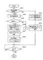
図10A及び図10Bは、サーバ1による有向グラフデータの作成処理のフローチャートの一例である。図10A及び図10Bに示されるフローチャートは、例えば、所定の周期で開始される。所定の周期は、例えば、分単位,時間単位,日単位,月単位で、センシング制御システム100の管理者によって設定される。
FIG. 10A and FIG. 10B are examples of a flowchart of directed graph data creation processing by the
OP21−OP28の処理は、各携帯端末2から受信される新規のイベント履歴データの総数に相当する回数実行される。変数Mは、1つの携帯端末2から受信した新規のイベント履歴データの処理対象を示すポインタであり、初期値は1である。変数Mが1であることは、該携帯端末2から受信した新規のイベント履歴データのうち、イベント発生時刻が最も古いものが処理対象であることを示す。以降、処理対象のイベント履歴データを、単に、M番目のイベント、と称する。
The processing of OP21-OP28 is executed a number of times corresponding to the total number of new event history data received from each
OP21では、データ作成部12は、M番目のイベントに該当するノードがノード表に登録されているか否かを判定する。M番目のイベントに該当するノードがノード表にある場合には(OP21:YES)、処理がOP23に進む。M番目のイベントに該当するノードがノード表にない場合には(OP21:NO)、処理がOP22に進む。
In OP21, the
OP22では、データ作成部12は、M番目のイベントにIDを割り当て、ノード表に追加する。次に処理がOP23に進む。
In OP22, the
OP23では、M番目のイベントが該当携帯端末2から受信された最後のイベント履歴データであるか否かを判定する。M番目のイベントが該当携帯端末2から受信された最後のイベント履歴データである場合には(OP23:YES)、データ作成部12は、次の携帯端末2のイベント履歴データの処理に移る。又は、全携帯端末2のイベント履歴データの処理が終了した場合には、処理がOP29に進む。
In OP23, it is determined whether or not the Mth event is the last event history data received from the
M番目のイベントが該当携帯端末2から受信された最後のイベント履歴データでない場合には(OP23:NO)、処理がOP24に進む。 If the Mth event is not the last event history data received from the mobile terminal 2 (OP23: NO), the process proceeds to OP24.
OP24では、データ作成部12は、M番目のイベントからM+1番目のイベントへの遷移に対応するアークが第1アーク表にあるか否かを判定する。M番目のイベントからM+1番目のイベントへの遷移に対応するアークが第1アーク表にある場合には(OP24:YES)、処理がOP25に進む。M番目のイベントからM+1番目のイベントへの遷移に対応するアークが第1アーク表にない場合には(OP24:NO)、処理がOP27に進み、データ作成部12は、第1及び第2アーク表に新規アークを追加する。次に処理がOP28に進む。
In OP24, the
OP25では、データ作成部12は、M番目のイベントとM+1番目のイベントとの時間間隔と、第1アーク表の対応アークの長さ(時間)とを比較する。M番目のイベントとM+1番目のイベントとの時間間隔が、第1アーク表の対応アークの長さ(時間)よりも短い場合には(OP25:YES)、処理がOP26に進む。OP26では、データ作成部12は、第1アーク表の対応アークの長さ(時間)をM番目のイベントとM+1番目のイベントとの時間間隔で上書きする。これによって、第1アーク表の長さは、最小値に更新される。次に処理がOP28に進む。
In OP25, the
M番目のイベントとM+1番目のイベントとの時間間隔が、第1アーク表の対応アークの長さ(時間)以上である場合には(OP25:NO)、第1アーク表の対応アークの長さ(時間)は更新されずに、処理がOP28に進む。 If the time interval between the Mth event and the M + 1th event is equal to or greater than the length (time) of the corresponding arc in the first arc table (OP25: NO), the length of the corresponding arc in the first arc table (Time) is not updated, and the process proceeds to OP28.
OP28では、データ作成部12は、ノード表,第1アーク表,第2アーク表のM番目のイベント及びM番目のイベントからM+1番目のイベントへの遷移に対応するアークに該当するログ発生個数をそれぞれインクリメントする。
In OP28, the
その後、変数Mはインクリメントされて、OP21−OP28の処理が繰り返し実行される。全携帯端末2の全イベント履歴データに対してOP21−OP28の処理が終了すると、処理がOP29に進む。
Thereafter, the variable M is incremented, and the processing of OP21 to OP28 is repeatedly executed. When the process of OP21-OP28 is completed for all event history data of all the
OP29では、データ作成部12は、全携帯端末2のOP21−OP28において処理した有向グラフデータをマージする。OP30では、データ作成部12は、有向グラフデータを各携帯端末2に送信する。その後、図10A及び図10Bに示される処理が終了する。
In OP29, the
サーバ1から有向グラフデータを受信すると、各携帯端末2は、有向グラフデータ格納部23に格納される有向グラフデータを受信したもので更新する。
When receiving the directed graph data from the
(イベント未検出状態でのセンシング制御処理)
第1実施形態では、最新のイベントのノードを有向グラフの起点とする。しかしながら、例えば、携帯端末2の起動時やセンシング制御プログラムの再起動時など、イベントが検出されていない状態では、起点となるノードが決定されていないため、有向グラフを作成することができない。そのため、最初にイベントが検出されるまでの間は、センシング制御を行うことができない。(Sensing control processing when no event is detected)
In the first embodiment, the node of the latest event is set as the starting point of the directed graph. However, for example, when the event is not detected, such as when the
そこで、第1実施形態では、携帯端末2は、絶対座標を取得可能なセンシング部26が携帯端末2に備えられる場合には、イベント未検出状態では、絶対座標を利用して有向グラフの起点となるノードを仮に設定して、有向グラフを作成し、センシング制御を行う。有向グラフの起点として仮に設定されるノードを、以降、仮ノード、と称する。絶対座標を取得可能なセンシング部26には、例えば、GPS受信モジュールを通じて絶対座標を取得するセンシング部26Cがある。
Therefore, in the first embodiment, when the
図11A及び図11Bは、絶対座標を利用する仮ノードの決定処理の一例を示す図である。図11Aでは、絶対座標より携帯端末2が領域A及び領域Bの範囲内に存在することが判定される場合の仮ノードの決定処理の一例が示される。
11A and 11B are diagrams illustrating an example of a provisional node determination process using absolute coordinates. FIG. 11A shows an example of a temporary node determination process in the case where it is determined from the absolute coordinates that the
複数の領域の範囲内に携帯端末2が存在する場合には、携帯端末2のセンシング制御部21は、領域の境界が近い方の領域内の存在(stay)イベントを仮ノードに決定する。各領域の境界の情報は、例えば、GPS場所データ27Cから取得することができる。
When the
例えば、図11Aに示される例では、絶対座標によって取得される携帯端末2の現在位置には、領域Aの境界の方が近いので、センシング制御部21は、領域Aの存在(stay)イベントに対応するノードを仮ノードに決定する。
For example, in the example shown in FIG. 11A, since the boundary of the region A is closer to the current position of the
仮ノードを決定すると、センシング制御部21は、仮ノードを起点に有向グラフを作成する。通常、領域内の存在(stay)イベントの後には、該領域からの退出(exit)イベントが発生する。そのため、仮ノードである、領域内の存在(stay)イベントのノードから、該領域からの退出(exit)イベントのノードまで、に含まれるノードのイベントは発生する確率が高い。したがって、センシング制御部21は、仮ノードから、仮ノードと同じ領域からの退出(exit)イベントに対応するノードまで、に含まれるノードに対応するセンシング部26をオンにする。
When the temporary node is determined, the
図11Aに示される例では、仮ノード55は、領域A内の存在(stay)イベントである。仮ノード55には、アーク65によってノード56が接続されており、ノード56にはアーク66によってノード57が接続されている。また、仮ノード55には、アーク67によってノード58が接続されており、ノード58にはアーク68によってノード57が接続されている。
In the example shown in FIG. 11A, the
ノード57は、領域Aの退出(exit)イベントである。したがって、図11Aに示される例では、仮ノード55からノード57までに含まれるノード56,ノード58,及びノード57に対応するセンシング部26がオンになる。
図11Bでは、絶対座標より携帯端末2がいずれの領域の範囲内にも存在していないことが判定される場合の仮ノードの決定処理の一例が示される。この場合には、携帯端末2のセンシング制御部21は、現在位置から領域境界が最も近い領域からの退出(exit)イベントに対応するノードを仮ノードに決定する。図11Bに示される例では、現在位置からは領域Bの境界が最も近いので、センシング制御部21は、領域Bからの退出(exit)イベントを仮ノードに決定する。
FIG. 11B shows an example of a provisional node determination process when it is determined from the absolute coordinates that the
仮ノードを決定すると、センシング制御部21は仮ノードを起点として有向グラフを作成する。以降は、イベントが検出されるまで、センシング制御部21は、時間経過につれて、仮ノードからのアークの長さの和が経過時間T+α以下のノードのセンシング部26をオンにする。Tは仮ノード決定からの経過時間である。αは、オフセット時間である。
When the temporary node is determined, the
図11Bに示される例では、仮ノード58Aは、領域Bからの退出(exit)イベントである。仮ノード58Aには、アーク69Aによってノード58Bが接続され、ノード58Bにはアーク69Bによってノード58Cが接続される。また、仮ノード58Aには、アーク69Cによってノード58Dが接続される。
In the example shown in FIG. 11B, the
図11Bにおいて、t3<t1であるとする。経過時間T+α<t3の場合には、いずれのセンシング部26もオフである。t3≦経過時間T+α<t1の場合には、ノード58Dに対応するセンシング部26がオンになる。t1≦経過時間T+α<t1+t2の場合には、ノード58Bとノード58Dとに対応するセンシング部26がオンになる。t1+t2≦経過時間T+αの場合には、ノード58B,ノード58C,ノード58Dに対応するセンシング部26がオンになる。
In FIG. 11B, it is assumed that t3 <t1. When the elapsed time T + α <t3, any sensing unit 26 is off. When t3 ≦ elapsed time T + α <t1, the sensing unit 26 corresponding to the
携帯端末2が絶対座標を取得可能なセンシング部26を備えていない場合には、センシング制御部21は、イベント未検出状態において、仮ノードを決定せず、また、有向グラフも生成せずに、センシング制御を行う。センシング制御部21は、携帯端末2が絶対座標を取得可能なセンシング部26を備えていない場合には、イベント未検出状態において、イベント発生率格納部25に格納されている各センシング部26のイベント発生率に応じて、各センシング部26の動作インターバルを設定する。
When the
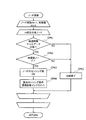
図12A及び図12Bは、携帯端末2によるイベント未検出状態でのセンシング制御処理のフローチャートの一例である。図12A及び図12Bに示されるフローチャートは、例えば、携帯端末2の起動に伴うセンシング制御プログラムの起動,センシング制御プログラムの再起動,等により開始される。
12A and 12B are an example of a flowchart of the sensing control process in the event non-detected state by the
OP31では、センシング制御部21は、携帯端末2に絶対座標を取得可能なセンシング部26が備えられているか否かを判定する。携帯端末2に絶対座標を取得可能なセンシング部26が備えられている場合には(OP31:YES)、処理がOP34に進む。携帯端末2に絶対座標を取得可能なセンシング部26が備えられていない場合には(OP31:NO)、処理がOP32に進む。
In OP31, the
OP32及びOP33は、携帯端末2に絶対座標を取得可能なセンシング部26が備えられていない場合のイベント未検出状態におけるセンシング制御処理である。OP32では、センシング制御部21は、イベント発生率格納部25から、各センシング部26のイベント発生率を読出し、イベント発生率の高い順に優先順位を設定する。
OP32 and OP33 are sensing control processes in the event non-detected state when the
OP33では、センシング制御部21は、優先順位毎にセンシング部26の動作モードを設定する。動作モードによって、センシング部26の動作インターバルが設定される。例えば、動作モードには優先モード,通常モード,待機モードがあり、それぞれ、動作インターバルは、30秒,1分,5分となる。なお、動作モードは、これに限られない。また、センシング部26の種別によって、動作モードのインターバルの値は異なる。
In OP33, the
例えば、センシング制御部21は、優先順位が1位のセンシング部26の動作モードを優先モードに設定する。例えば、センシング制御部21は、優先順位が2位のセンシング部26の動作モードを通常モードに設定する。例えば、センシング制御部21は、優先順位が3位以下のセンシング部26の動作モードを待機モードに設定する。
For example, the
なお、OP32及びOP33では、各センシング部26にイベント発生率に応じて優先順位を割り当てて、優先順位に応じて動作モードを決定するが、これに限られない。例えば、イベント発生率の閾値を設定し、該閾値とイベント発生率との関係に応じて、各センシング部26の動作モードが決定されてもよい。 In OP32 and OP33, priority is assigned to each sensing unit 26 according to the event occurrence rate, and the operation mode is determined according to the priority. However, the present invention is not limited to this. For example, an event occurrence rate threshold value may be set, and the operation mode of each sensing unit 26 may be determined according to the relationship between the threshold value and the event occurrence rate.
OP34では、センシング制御部21は、絶対座標を取得可能なセンシング部26に対して、絶対座標の取得を指示し、絶対座標を取得する。次に処理がOP35に進む。
In OP34, the
OP35では、センシング制御部21は、絶対座標から、携帯端末2がいずれかの領域内に存在しているか否かを判定する。携帯端末2がいずれかの領域内に存在している場合には(OP35:YES)、処理がOP36に進む。携帯端末2がいずれの領域内にも存在していない場合には(OP35:NO)、処理がOP40に進む。
In OP35, the
OP36からOP38の処理は、携帯端末2がいずれかの領域内に存在している場合のイベント未検出状態におけるセンシング制御処理である。OP36では、センシング制御部21は、現在位置から最も境界の近い領域内の存在(stay)イベントを仮ノードに設定する。次に、処理がOP37に進む。
The processes from OP36 to OP38 are sensing control processes in an event non-detected state when the
OP37では、センシング制御部21は、仮ノードを起点とする有向グラフに使用されるデータを有向グラフデータ格納部23から取得し、有向グラフを作成する。作成された有向グラフは、例えば、RAM 202Bの一時的な記憶領域に格納され、図12A及び図12Bの処理が終了すると削除される。次に処理がOP38に進む。
In OP37, the
OP38では、センシング制御部21は、有向グラフにおいて、仮ノードから仮ノードと同じ領域からの退出(exit)イベントのノードまでに含まれるノードに対応するセンシング部26をオンにする。次に処理がOP39に進む。
In OP38, the
OP39では、センシング制御部21は、センシング部26によるイベント発生の検出を待機する。いずれかのセンシング部26によってイベントの発生が検出された場合には(OP39:YES)、図12A及び図12Bに示される処理が終了し、次に、イベント検出状態におけるセンシング制御処理(後述図13)が開始される。
In OP39, the
OP40−OP45の処理は、携帯端末2がいずれの領域内にも存在していない場合のイベント未検出状態におけるセンシング制御処理である。OP40では、センシング制御部21は、現在位置から最も境界の近い領域からの退出(exit)イベントを仮ノードに設定する。次に、処理がOP41に進む。
The process of OP40-OP45 is a sensing control process in the event undetected state when the
OP41では、センシング制御部21は、仮ノードを起点とする有向グラフに使用されるデータを有向グラフデータ格納部23から取得し、有向グラフを作成する。作成された有向グラフは、例えば、RAM 202Bの一時的な記憶領域に格納され、図12A及び図12Bの処理が終了すると削除される。次に処理がOP42に進む。
In OP41, the
OP42では、センシング制御部21は、仮ノードからノード探索を行う。ノード探索は、各ノードが所定の条件を満たすか否かを判定する処理である。所定の条件は、例えば、仮ノード(起点ノード)からのアークの和が経過時間T+αより大きいこと、及び、ノード探索済みであること、である。所定の条件が満たされた場合には、該分岐においてノード探索は終了する。ノード探索処理の詳細については、図14において後述される。
In OP42, the
OP43では、センシング制御部21は、ノード探索の結果に従って、センシング制御を行う。ノード探索の結果に従ったセンシング制御の詳細については、後述される。例えば、OP42のノード探索処理によって、センシング制御部21は、アークの和が経過時間T+α以下であるノードのセンシング部26をオンにすることを判定する。OP43では、センシング制御部21は、ノード探索の結果、オンにすることを判定した経過時間T+α以下であるノードに対応するセンシング部26をオンにする。次に処理がOP44に進む。
In OP43, the
OP44では、センシング制御部21は、センシング部26によるイベント発生の検出を待機する。いずれかのセンシング部26によってイベントの発生が検出された場合には(OP44:YES)、図12A及び図12Bに示される処理が終了し、次に、イベント検出状態におけるセンシング制御処理(後述図13)が開始される。
In OP44, the
所定時間イベントの発生が検出されない場合には(OP44:NO)、処理がOP45に進む。OP45では、センシング制御部21は、経過時間Tを更新する。その後処理がOP42に戻り、更新された経過時間Tを用いてノード探索が行われる。
If the occurrence of an event for a predetermined time is not detected (OP44: NO), the process proceeds to OP45. In OP45, the
なお、上述の携帯端末2がいずれかの領域内に存在している場合のイベント未検出状態におけるセンシング制御処理では、仮ノード(起点ノード)から仮ノードと同じ領域からの退出(exit)イベントのノードまでに含まれる全てのノードのセンシング部26をオンにする処理が行われる。これによって、ノード探索処理にかかる負荷を低減することができる。ただし、これに限られず、携帯端末2がいずれかの領域内に存在している場合にも、携帯端末2がいずれの領域内にも存在していない場合と同様にして、ノード探索処理が行われてもよい。
In the sensing control process in the event undetected state when the above-described
(イベント検出状態におけるセンシング制御処理)
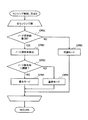
図13は、携帯端末2におけるイベント検出状態におけるセンシング制御処理のフローチャートの一例である。イベント検出状態とは、少なくとも1つのイベントの発生が検出されている状態である。図13に示されるフローチャートは、イベント発生の検出、又は所定の周期で開始される。所定の周期は、例えば、秒単位,分単位で設定される。(Sensing control process in event detection state)
FIG. 13 is an example of a flowchart of the sensing control process in the event detection state in the
OP51−OP53の処理は、イベントの発生が検出された場合の処理である。イベントの発生の検出は、各センシング部26によって行われる。 The processing from OP51 to OP53 is processing when occurrence of an event is detected. Detection of event occurrence is performed by each sensing unit 26.
OP51では、センシング制御部21は、経過時間Tをリセットする。ここでの経過時間Tは、起点ノードのイベントが発生してからの経過時間を示す。OP52では、センシング制御部21は、有向グラフの起点ノードを、最新のイベントのノードに変更する。OP53では、センシング制御部21は、有向グラフに使用されるデータを有向グラフデータ格納部23から取得し、有向グラフを作成する。作成された有向グラフは、例えば、RAM 202Bの一時的な記憶領域に格納され、図13の処理が終了すると削除される。次に処理がOP55に進む。
In OP51, the
OP54は、最新のイベントの検出後、次にイベントが検出されるまでの間に、所定の周期で行われる処理である。OP54では、センシング制御部21は、経過時間Tを更新する。次に処理がOP55に進む。
OP54 is a process performed at a predetermined cycle after the latest event is detected and until the next event is detected. In OP54, the
OP55では、センシング制御部21は、作成した有向グラフを起点ノードからノード探索する。ノード探索によって、起点ノードからのアークの和が経過時間以下のノードが抽出される。ノード探索の詳細は、後述する。
In OP55, the
OP56では、センシング制御部21は、ノード探索結果にしたがって、センシング制御を行う。センシング制御処理の詳細は、後述する。OP56の処理が終了すると、図13に示される処理が終了する。
In OP56, the
(ノード探索処理)
図14は、ノード探索処理のフローチャートの一例である。有向グラフは、起点ノードが決定されると、起点ノードを始点とするアークが第1アーク表から抽出され、抽出されたアークの終点に位置するノードが決定され、さらに決定されたノードを始点とするアークが第1アーク表から抽出されることが繰り返されることによって作成される。
(Node search process)
FIG. 14 is an example of a flowchart of the node search process. In the directed graph, when a starting node is determined, an arc starting from the starting node is extracted from the first arc table, a node located at the end point of the extracted arc is determined, and the determined node is the starting point . The arc is created by repeating the extraction from the first arc table.
図14に示される例では、起点ノードから1つのアークを介して接続されるノードを、1段目のノードとする。起点ノードからm個のアーク及びm−1個のノードを介して接続されるノードをm段目のノードとする。図14において、mは、ノードの段数を示す変数であり、正の整数である。変数mの初期値は、1である。 In the example shown in FIG. 14, a node connected from the starting node via one arc is a first-stage node. A node connected from the starting node via m arcs and m−1 nodes is defined as an m-th stage node. In FIG. 14, m is a variable indicating the number of stages of nodes, and is a positive integer. The initial value of the variable m is 1.
OP61からOP65の処理は、図12BのOP41,図13のOP53において作成される有向グラフ内の、m段目の全てのノードに対して実行される。以降、処理対象のノードを対象ノードとする。 Processing from OP61 OP65 is, OP 41 in FIG. 12B, in the directed graph created in OP53 in FIG 13, is performed for all nodes of the m-th stage. Hereinafter, the processing target node is set as a target node.
OP61では、センシング制御部21は、経過時間T+αが起点ノードから対象ノードまでに含まれるアークの長さの和以上であるか否かを判定する。経過時間T+αが起点ノードから対象ノードまでに含まれるアークの長さの和以上である場合には(OP61:YES)、処理がOP62に進む。経過時間T+αが起点ノードから対象ノードまでに含まれるアークの長さの和未満である場合には(OP61:NO)、処理がOP65に進む。
In OP61, the
OP62では、センシング制御部21は、対象ノードは未探索ノードであるか否かを判定する。対象ノードが未探索ノードである場合には(OP62:YES)、センシング制御部21は、対象ノードを探索済みとRAM 202Bの一時的な記憶領域に記録する。ノードの探索済みの記録は、ノード探索処理の終了とともに削除される。その後処理がOP63に進む。対象ノードが探索済みのノードである場合には(OP62:NO)、OP65に処理が進む。対象ノードが探索済みであるか否かは、RAM 202Bの一時的な記憶領域内の探索済みのノードの記録を参照することで判定される。
In OP62, the
OP63では、センシング制御部21は、対象ノードのセンシング部26をオンにすることを判定する。次に処理がOP64に進む。
In OP63, the
OP64では、センシング制御部21は、OP63でオンにすることを判定されたセンシング部26の探索回数をインクリメントする。各センシング部26の探索回数は、例えば、RAM 202Bの一時的な記憶領域に記録され、初期値は0であり、ノード探索処理開始時にリセットされる。
In OP64, the
OP65では、起点ノードから対象ノードまでに含まれるアークの長さの和が経過時間T+αよりも大きい、又は、対象ノードが探索済みのノードであるため、センシング制御部21は、対象ノードから先の分岐については、ノード探索を行わずに、分岐終了とする。対象ノードが探索済みである場合には、分岐終了にすることによって、探索処理のループの発生を低減することができる。
In OP65, since the sum of the lengths of arcs included from the starting node to the target node is greater than the elapsed time T + α, or the target node is a searched node, the
OP64又はOP65の処理が終了すると、m段目の次のノードについてOP61から処理が行われる。対象ノードがm段目の最後のノードである場合には、変数mがインクリメントされて、次の段の最初ノードについて、OP61から処理が行われる。有向グラフ内の対象ノードとなり得るノードについて、OP61−OP65の処理が終了すると、図14に示されるノード探索処理が終了する。このノード探索処理の結果に基づいて、次に、センシング制御処理が実行される。なお、図14に示されるフローチャートは、一例であって、これに限られない。 When the process of OP64 or OP65 ends, the process is performed from OP61 on the next node in the m-th stage. When the target node is the last node in the m-th stage, the variable m is incremented, and the process is performed from OP61 for the first node in the next stage. When the process of OP61-OP65 is completed for a node that can be a target node in the directed graph, the node search process illustrated in FIG. 14 is completed. Next, a sensing control process is executed based on the result of the node search process. Note that the flowchart shown in FIG. 14 is an example, and the present invention is not limited to this.
(センシング制御処理)
第1実施形態では、ノード探索処理の結果に従って行われるセンシング制御処理には、以下の4つの方法がある。いずれの方法が採用されてもよい。(Sensing control processing)
In the first embodiment, there are the following four methods for sensing control processing performed according to the result of the node search processing. Any method may be adopted.
1つ目の方法(方法1)は、ノード探索処理によってオンにすると判定されたセンシング部26をオンにし、それ以外のセンシング部26をオフにする方法である。 The first method (method 1) is a method in which the sensing unit 26 determined to be turned on by the node search process is turned on and the other sensing units 26 are turned off.
2つ目の方法(方法2)は、ノード探索処理によってオンにすると判定されたセンシング部26の動作モードを通常モードにし、それ以外のセンシング部26の動作モードを待機モードにする方法である。 The second method (method 2) is a method in which the operation mode of the sensing unit 26 determined to be turned on by the node search process is set to the normal mode, and the other operation modes of the sensing unit 26 are set to the standby mode.
3つ目の方法(方法3)は、ノード探索処理によってオンにすると判定されたセンシング部26の動作モードを、ノードが探索された割合に応じて、優先モード又は通常モードにし、それ以外のセンシング部26の動作モードを待機モードにする方法である。 In the third method (method 3), the operation mode of the sensing unit 26 determined to be turned on by the node search process is set to the priority mode or the normal mode according to the ratio of the node searched, and other sensing is performed. This is a method of setting the operation mode of the unit 26 to the standby mode.
4つ目の方法(方法4)は、ノード探索処理によってオンにすると判定されたセンシング部26の動作モードを、イベント(ノード)の発生間隔の分布に応じて、優先モード又は通常モードに設定し、それ以外のセンシング部26の動作モードを待機モードにする方法である。 In the fourth method (method 4), the operation mode of the sensing unit 26 determined to be turned on by the node search process is set to the priority mode or the normal mode according to the distribution of event (node) occurrence intervals. This is a method of setting the other operation mode of the sensing unit 26 to the standby mode.
図15は、ノード探索処理の結果に従って行われるセンシング制御処理の方法1及び方法2のフローチャートの一例である。まず、方法1のフローチャートについて説明する。
FIG. 15 is an example of a flowchart of the
OP71−OP73の処理は、携帯端末2が備える全センシング部26について実行される。OP71では、センシング制御部21は、ノード探索処理の結果、処理対象のセンシング部26はオンにすることを判定されたか否かを判定する。
The processes of OP71 to OP73 are executed for all the sensing units 26 included in the
処理対象のセンシング部26がノード探索処理によってオンにすることを判定されている場合には(OP71:YES)、処理がOP72に進む。OP72では、センシング制御部21は、処理対象のセンシング部26をオンにする。
If it is determined that the sensing unit 26 to be processed is turned on by the node search process (OP71: YES), the process proceeds to OP72. In OP72, the
処理対象のセンシング部26がノード探索処理によってオンにすることを判定されていない場合には(OP71:NO)、処理がOP73に進む。OP73では、センシング制御部21は、処理対象のセンシング部26をオフにする。
When the sensing unit 26 to be processed is not determined to be turned on by the node search process (OP71: NO), the process proceeds to OP73. In OP73, the
OP72又はOP73の処理が終了すると、次のセンシング部26についてOP71から処理が繰り返し行われる。処理対象のセンシング部26が最後のセンシング部である場合には、図15に示される処理が終了する。 When the process of OP72 or OP73 is completed, the process is repeated from OP71 for the next sensing unit 26. When the sensing unit 26 to be processed is the last sensing unit, the process illustrated in FIG. 15 ends.
方法2の場合には、処理対象のセンシング部26がノード探索処理によってオンにすることを判定されている場合には(OP71:YES)、OP72では、センシング制御部21は、処理対象のセンシング部26の動作モードを通常モードにする。一方、処理対象のセンシング部26がノード探索処理によってオンにすることを判定されていない場合には(OP71:NO)、OP73では、センシング制御部21は、処理対象のセンシング部26の動作モードを待機モードにする。
In the case of the
方法1の場合には、ノード探索処理の結果オンにすることが判定されたセンシング部26がオンになり、それ以外のセンシング部26はオフになる。そのため、オンになるセンシング部26の数を少なく抑えることができ、センシング部26による消費電力を低減することができる。
In the case of the
方法2の場合には、ノード探索処理の結果オンにすることが判定されたセンシング部26の動作モードが通常モードになり、それ以外のセンシング部26の動作モードは待機モードになる。待機モードの場合には、通常モードに比べてセンシング部26の動作インターバルが長い。そのため、方法2によれば、待機モードのセンシング26の動作回数を少なくすることができるため、センシング部26による消費電力を低減することができる。
In the case of the
図16は、ノード探索処理の結果に従って行われるセンシング制御処理の方法3のフローチャートの一例である。方法3では、各センシング部26について、対応するイベントのノードが探索された割合によって、動作モードが決定される。 FIG. 16 is an example of a flowchart of the method 3 of the sensing control process performed according to the result of the node search process. In the method 3, the operation mode is determined for each sensing unit 26 according to the rate at which the corresponding event node is searched.
OP81−OP86の処理は、携帯端末2が備える全センシング部26について実行される。OP81では、センシング制御部21は、ノード探索処理の結果、処理対象のセンシング部26はオンにすることを判定されたか否かを判定する。
The processing of OP81-OP86 is executed for all the sensing units 26 provided in the
処理対象のセンシング部26がノード探索処理によってオンにすることを判定されている場合には(OP81:YES)、処理がOP82に進む。OP82では、センシング制御部21は、処理対象のセンシング部26のノード探索率を算出する。
If it is determined that the sensing unit 26 to be processed is to be turned on by the node search process (OP81: YES), the process proceeds to OP82. In OP82, the
ノード探索率は、ノード探索処理における処理対象のセンシング部26の探索回数を全センシング部26の総探索回数で割った値である。ノード探索率は、各センシング部26によって検出されるイベントの発生の度合いを示す。各センシング部26の探索回数は、ノード探索処理内で、例えば、図14のOP64の処理においてカウントされる。次に処理がOP83に進む。 The node search rate is a value obtained by dividing the number of searches of the sensing unit 26 to be processed in the node search process by the total number of searches of all the sensing units 26. The node search rate indicates the degree of occurrence of an event detected by each sensing unit 26. The number of searches of each sensing unit 26 is counted in the process of OP64 in FIG. 14, for example, in the node search process. Next, the process proceeds to OP83.
OP83では、センシング制御部21は、算出した処理対象のセンシング部26のノード探索率が所定の閾値より大きいか否かを判定する。この閾値は、処理対象のセンシング部26の動作モードを優先モードまたは通常モードに決定するために使用され、例えば、0から1までの値である。処理対象のセンシング部26のノード探索率が所定の閾値より大きい場合には(OP83:YES)、処理がOP84に進み、OP84では、センシング制御部21は、処理対象のセンシング部26の動作モードを優先モードに設定する。処理対象のセンシング部26のノード探索率が所定の閾値以下の場合には(OP83:NO)、処理がOP85に進み、OP85では、センシング制御部21は、処理対象のセンシング部26の動作モードを通常モードに設定する。
In OP83, the
処理対象のセンシング部26がノード探索処理によってオンにすることを判定されていない場合には(OP81:NO)、処理がOP86に進む。OP86では、センシング制御部21は、処理対象のセンシング部26の動作モードを待機モードにする。
When it is not determined that the sensing unit 26 to be processed is turned on by the node search process (OP81: NO), the process proceeds to OP86. In OP86, the
OP84,OP85,またはOP86の処理が終了すると、次のセンシング部26についてOP81から処理が繰り返し行われる。処理対象のセンシング部26が最後のセンシング部である場合には、図16に示される処理が終了する。 When the process of OP84, OP85, or OP86 is completed, the process is repeated from OP81 for the next sensing unit 26. When the sensing unit 26 to be processed is the last sensing unit, the process illustrated in FIG. 16 ends.
方法3の場合には、処理対象のセンシング部26のノード探索率に応じて段階的に動作モードが決定される。ノード探索率は、各センシング部26によって検出されるイベントの発生する度合いを示すので、方法3によれば、イベントの発生の確率が高いセンシング部26を優先モードで動作させることができる。 In the case of the method 3, the operation mode is determined stepwise according to the node search rate of the sensing unit 26 to be processed. Since the node search rate indicates the degree of occurrence of the event detected by each sensing unit 26, according to the method 3, the sensing unit 26 having a high probability of event occurrence can be operated in the priority mode.
方法3では、ノード探索率はノード探索処理における各センシング部26の探索回数を用いて算出されるが、ノード探索率は、各アークの第1アーク表のログ発生個数を用いて算出されてもよい。例えば、図14のOP64において、処理対象ノードのセンシング部26の探索回数に、処理対象ノードと一段前のノードとを接続するアークの第1アーク表のログ発生個数を加算して、該センシング部26の探索回数をカウントする。ノード探索率は、この探索回数を用いて算出される。これによって、各センシング部26の探索率を、アークのログ発生個数によって重みづけして算出することができる。 In Method 3, the node search rate is calculated using the number of searches of each sensing unit 26 in the node search process, but the node search rate may be calculated using the number of logs generated in the first arc table of each arc. Good. For example, in OP64 of FIG. 14, the number of logs generated in the first arc table of the arc connecting the processing target node and the previous node is added to the number of searches of the sensing unit 26 of the processing target node, and the sensing unit 26 search times are counted. The node search rate is calculated using the number of searches. Accordingly, the search rate of each sensing unit 26 can be calculated by weighting the number of arc logs.
図17は、ノード探索処理の結果に従って行われるセンシング制御処理の方法4について説明するための図である。方法4は、イベントの発生間隔の分布(アークの長さの分布)に応じて、センシング部26の動作モードを設定する方法である。 FIG. 17 is a diagram for explaining a method 4 of the sensing control process performed according to the result of the node search process. Method 4 is a method of setting the operation mode of the sensing unit 26 in accordance with the distribution of event occurrence intervals (arc length distribution).
図17に示される有向グラフでは、起点ノード59Aには、アーク69Eによってノード59Bが接続されている。また、起点ノード59Aには、アーク69Fによってノード59Cが接続されている。
In the directed graph shown in FIG. 17, the
第1アーク表には、イベントの履歴の中で、イベントの発生間隔が最も短い時間が、アークの長さとして格納されているため、携帯端末2によって作成される有向グラフでは、アークの長さは、過去のログの中で最も短いイベント間隔である。しかしながら、実際には、ノードのイベントの発生間隔は、分布を持つ。
In the first arc table, since the time with the shortest event occurrence interval is stored as the arc length in the event history, in the directed graph created by the
例えば、ノード59Cは、起点ノード59Aの発生から最速でt4後に発生する履歴があるが、最もログ発生個数が多いのは、t4からさらにβ時間経過後である。例えば、ノード59Bは、起点ノード59Aの発生から最速でt2後に発生する履歴があるが、最もログ発生個数が多いのは、t2からさらにγ時間経過後である。
For example, the
したがって、方法4では、所定の単位で区切られた時間帯におけるログ発生個数の分布を考慮し、ログ発生個数が少ない時間帯にはセンシング部26の動作モードは通常モードに、ログ発生個数が多い時間帯にはセンシング部26の動作モードは優先モードに設定される。所定の単位に区切られた時間帯とは、例えば、1分,5分,10分等の単位で区切られた時間帯である。ログ発生個数の時間別の分布は、第2アーク表に格納されている(図7参照)。図7では、5分単位で区切られた時間帯のログ発生の分布が格納される。 Therefore, in the method 4, considering the distribution of the log generation number in the time zone divided by a predetermined unit, the operation mode of the sensing unit 26 is set to the normal mode and the log generation number is large in the time zone where the log generation number is small. In the time zone, the operation mode of the sensing unit 26 is set to the priority mode. The time zone divided into predetermined units is, for example, a time zone divided in units of 1 minute, 5 minutes, 10 minutes, and the like. The distribution of the number of logs generated by time is stored in the second arc table (see FIG. 7). In FIG. 7, the distribution of log occurrences in the time period divided in units of 5 minutes is stored.
図18は、ノード探索処理の結果に従って行われるセンシング制御処理の方法4のフローチャートの一例である。 FIG. 18 is an example of a flowchart of the method 4 of the sensing control process performed according to the result of the node search process.
OP91−OP98の処理は、携帯端末2が備える全センシング部26について実行される。OP91では、センシング制御部21は、ノード探索処理の結果、処理対象のセンシング部26はオンにすることを判定されたか否かを判定する。
The processes of OP91 to OP98 are executed for all the sensing units 26 included in the
処理対象のセンシング部26がノード探索処理によってオンにすることを判定されている場合には(OP91:YES)、処理がOP92に進む。OP92では、センシング制御部21は、経過時間T+αにおいて、有向グラフ内の起点ノードからノード探索済みのノードまでに含まれる全アークのログ発生回数の総和を第1アーク表から算出する。次に処理がOP93に進む。
When it is determined that the sensing unit 26 to be processed is turned on by the node search process (OP91: YES), the process proceeds to OP92. In OP92, the
OP93では、センシング制御部21は、有向グラフ内の処理対象のセンシング部26のノード探索済みのノードを遷移先(第1アーク表における“ノードID(to))とするアークの該当する時間帯のログ発生回数の総和を第2アーク表から算出する。該アークの該当する時間帯とは、該アークを含む起点ノードから該アークの遷移先のノードまでに含まれるアークの和を経過時間T+αから引いた時間が属する第2アーク表に定義される時間帯である。次に処理がOP94に進む。
In OP93, the
OP94では、センシング制御部21は、OP93で第2アーク表から算出した総和をOP92で第1アーク表から算出した総和で割った比率を算出する。この比率は、有向グラフでの、経過時間T+αにおける処理対象のセンシング部26が使用される割合を示す。次に処理がOP95に進む。
In OP94, sensing
OP95では、センシング制御部21は、算出した処理対象のセンシング部26の比率が所定の閾値より大きいか否かを判定する。この閾値は、処理対象のセンシング部26の動作モードを優先モードまたは通常モードに決定するために使用される。処理対象のセンシング部26の比率が所定の閾値より大きい場合には(OP95:YES)、処理がOP96に進み、OP96では、センシング制御部21は、処理対象のセンシング部26の動作モードを優先モードに設定する。処理対象のセンシング部26の比率が所定の閾値以下の場合には(OP95:NO)、処理がOP97に進み、OP97では、センシング制御部21は、処理対象のセンシング部26の動作モードを通常モードに設定する。
In OP95, the
処理対象のセンシング部26がノード探索処理によってオンにすることを判定されていない場合には(OP91:NO)、処理がOP98に進む。OP98では、センシング制御部21は、処理対象のセンシング部26の動作モードを待機モードにする。
When the sensing unit 26 to be processed is not determined to be turned on by the node search process (OP91: NO), the process proceeds to OP98. In OP98, the
OP96,OP97,またはOP98の処理が終了すると、次のセンシング部26についてOP91から処理が繰り返し行われる。処理対象のセンシング部26が最後のセンシング部である場合には、図18に示される処理が終了する。 When the process of OP96, OP97, or OP98 is completed, the process is repeated from OP91 for the next sensing unit 26. When the sensing unit 26 to be processed is the last sensing unit, the process illustrated in FIG. 18 ends.
方法4の場合には、経過時間T+αにおける処理対象のセンシング部26が使用される割合に応じて段階的に動作モードが決定される。所定のイベントから次のイベントが発生するまでの時間、すなわち、イベントの発生間隔には分布があり、時間経過によってイベントの発生する可能性は変化する。すなわち、経過時間によってセンシング部26が使用される割合は変化する。したがって、方法4によれば、イベントが発生する可能性の高い時間帯には、該イベントを検出するセンシング部26が優先モードで動作しているので、イベントをより精度よく検出できる。また、イベントが発生する可能性が低い時間帯には、該イベントを検出するセンシング部26は通常モードで動作しているので、消費電力を少なく抑えることができる。 In the case of the method 4, the operation mode is determined stepwise in accordance with the ratio of the processing target sensing unit 26 used in the elapsed time T + α. There is a distribution in the time from a predetermined event until the next event occurs, that is, the event occurrence interval, and the possibility of the event changing with the passage of time. That is, the rate at which the sensing unit 26 is used varies depending on the elapsed time. Therefore, according to the method 4, since the sensing unit 26 that detects the event operates in the priority mode in a time zone where the event is highly likely to occur, the event can be detected with higher accuracy. In addition, during a time period when an event is unlikely to occur, the sensing unit 26 that detects the event operates in the normal mode, so that power consumption can be reduced.
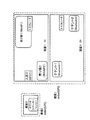
<適用例>
第1実施形態で説明されたセンシング制御処理は、例えば、顧客にショッピングセンタ内のエリアに応じた店舗情報や売り場情報を配信するサービスや、ショッピングエリアスタッフの各エリアでの作業や確認業務を支援するサービスがある。<Application example>
The sensing control process described in the first embodiment supports, for example, a service that distributes store information and sales floor information according to the area in the shopping center to customers, and work and confirmation work in each area of the shopping area staff There is a service to do.
図19は、ショッピングセンタにおける位置関係の例を示す図である。図19に示される例では、ショッピングセンタには、建屋1と建屋2とが存在する。この建屋1及び建屋2は、そのまま、GPSのセンシング部26Cによって検知される領域である。ショッピングセンタの敷地内の屋外では、GPSで位置を検出することができる。
FIG. 19 is a diagram illustrating an example of the positional relationship in the shopping center. In the example shown in FIG. 19, there are a
建屋1の入退口には、NFC1がユーザへのポイント加点のため設置されている。ポイント加点を所望するユーザは、携帯端末2をNFC1に接触又は所定距離まで近づける。建屋1の1階の売り場1は、Wi−Fiアクセスポイント1に紐づく場所IDが定義されている。建屋1の1階の売り場2は、Wi−Fiアクセスポイント2に紐づく場所IDが定義されている。
An
建屋1の2階のテナント1は、Bluetooth機器1に紐づく場所IDが定義されている。建屋1の2階のテナント4は、Bluetooth機器4に紐づく場所IDが定義されている。建屋2のイベントスペース1では、可聴範囲外の音波信号を出力する音波信号出力機器1に紐づく場所IDが定義されている。
The
なお、図19に示される例では、Wi−Fiアクセスポイント1,2,NFC1,Bluetooth機器1,4,音波信号出力機器1の絶対座標は管理されておらず、これらの位置関係は、システム上では不明であるとする。
In the example shown in FIG. 19, the absolute coordinates of the Wi-
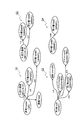
図20は、第1実施形態に係るセンシング制御において作成される有向グラフの例を示す図である。図20に示される有向グラフは、サーバ1によってイベント履歴データから作成されるものである。携帯端末2は、Wi−Fiアクセスポイント1,2,NFC1,Bluetooth機器1,2,音波信号出力機器1を検出可能なセンシング部26を備えていることとする。
FIG. 20 is a diagram illustrating an example of a directed graph created in the sensing control according to the first embodiment. The directed graph shown in FIG. 20 is created from the event history data by the
例えば、有向グラフG1では、起点ノードとしてのイベントノードと入退口通過イベントノードとは、長さ1分のアークで結合されている。また、有向グラフG1では、建屋1enterのイベントノードは、売り場2enterイベントノードとは長さ2分のアークで、売り場3enterイベントノードとは長さ4分のアークで、建屋1exitイベントノードとは長さ10秒のアークで結合されている。 For example, in the directed graph G1, the event node as the origin node and the entrance / exit passage event node are connected by an arc having a length of 1 minute. In the directed graph G1, the event node of the building 1enter is an arc of 2 minutes in length with the sales floor 2enter event node, an arc of 4 minutes in length with the sales floor 3enter event node, and is 10 in length with the building 1exit event node. Combined with arc of seconds.
例えば、有向グラフG2では、起点ノードとしての入退口通過イベントノードは、売り場2enterイベントノードとは長さ1分のアークで、売り場1enterイベントノードとは長さ3分のアークで結合されている。 For example, in the directed graph G2, the entrance / exit passing event node as the starting point node is connected to the sales floor 2enter event node by an arc of 1 minute in length and is connected to the sales floor 1enter event node by an arc of 3 minutes in length.
例えば、有向グラフG3では、起点ノードとしての売り場1exitイベントノードは、建屋1exitイベントノードとは長さ4分のアークで、テナント4enterイベントノードとは長さ2分のアークで、テナント1enterイベントノードとは長さ6分のアークで、売り場2enterイベントノードとは長さ2分のアークで、結合されている。 For example, in the directed graph G3, the sales floor 1exit event node as an origin node is an arc of 4 minutes in length with the building 1exit event node, an arc of 2 minutes in length with the tenant 4enter event node, and what is the tenant 1enter event node ? The arc is 6 minutes in length, and is connected to the sales floor 2enter event node by an arc of 2 minutes in length.
例えば、有向グラフG4では、起点ノードとしての売り場1enterイベントノードは、売り場1exitイベントノードと長さ10秒のアークで結合されている。 For example, the directed graph G4, sales 1enter event nodes as the source node is coupled with an arc of sales floor 1exit event node and the length 10 seconds.
方法4でセンシング制御が行われる場合には、以下のようにしてセンシング制御が行われる。なお、以下の説明では、便宜上センシング部を、単に、種別で記載する。 When sensing control is performed by method 4, sensing control is performed as follows. In the following description, the sensing unit is simply described by type for convenience.
建屋1enterイベントの発生時(T=0)には、有向グラフG1が生成され、有向グラフG1についてノード探索が行われる。経過時間のオフセット時間を1分(=α)とすると、建屋1enterイベントの発生時(T=0)には、アークの長さがT+α(=1分)以下となる入退口通過イベントノードのNFCと建屋1exitイベントノードのGPSとが優先モードで動作する。それ以外のセンシング部26は、待機モードで動作する。第2アーク表において、入退口通過イベントのログ発生個数は、時間の経過とともに少なくなっていくことが記録されているとすると、時間の経過とともに、NFCは、優先モードから通常モードへと動作モードが遷移する。
In the event of the building 1enter event (T = 0), the directed graph G1 is generated, the node search is performed for the directed
新たにイベントが検出されず経過時間が1分になる場合には、アークの長さがT+α(=2分)以下となる売り場2enterイベントノードのWi−Fiも優先モードで動作するようになる。 When no new event is detected and the elapsed time is 1 minute, the Wi-Fi of the sales floor 2enter event node whose arc length is equal to or shorter than T + α (= 2 minutes) also operates in the priority mode.
売り場1exitイベントが検出される場合には、1分経過後(経過時間T=1分)にはアークの長さが経過時間T+α(=2分)以下となるテナント4enterイベントノードのBluetoothと、売り場2enterイベントノードのWi−Fiとが優先モード又は通常モードで動作する。このとき、GPSは、ノード探索されずに待機モードで動作することになる。さらに2分経過すると(経過時間T=3分)、アークの長さが経過時間T+α(=4分)以下となり、建屋1exitイベントノードのGPSが優先モード又は通常モードで動作し始める。 If a sales floor 1exit event is detected, the tenant 4enter event node 's Bluetooth whose arc length is equal to or less than the elapsed time T + α (= 2 minutes) after 1 minute has elapsed (elapsed time T = 1 minute), and the sales floor The 2enter event node Wi-Fi operates in the priority mode or the normal mode. At this time, the GPS operates in a standby mode without searching for a node. When 2 minutes elapse (elapsed time T = 3 minutes), the arc length becomes equal to or less than the elapsed time T + α (= 4 minutes), and the GPS of the building 1exit event node starts to operate in the priority mode or the normal mode.
例えば、動作インターバルを優先モードで10秒、通常モードで1分、待機モードで3分とする場合、優先モードは、通常モードの6倍、待機モードの18倍の動作回数となる。したがって、上述のようにセンシング部が制御されることによって、1分間複数のセンシング部26が待機モードになることによっても、全センシング部26による動作回数を減らすことができ、省電力化が図れることがわかる。 For example, when the operation interval is 10 seconds in the priority mode, 1 minute in the normal mode, and 3 minutes in the standby mode, the priority mode is 6 times as many times as the normal mode and 18 times as many times as the standby mode. Therefore, by controlling the sensing unit as described above, the number of operations by all the sensing units 26 can be reduced even when the plurality of sensing units 26 are in the standby mode for one minute, and power saving can be achieved. I understand.
また、例えば、有向グラフG1に注目してみると、建屋1enterイベントノードに接続されるイベントノードは、建屋1の1階に含まれる場所のイベントノードであり、各場所の地理的位置関係と有向グラフG1のノードの位置関係とが類似していることが見て取れる。第1実施形態において、イベントは、携帯端末2の移動に起因して発生し、イベント発生間隔は、すなわち、場所間の移動時間である。移動時間と場所間の距離とは、速度について比例関係にあるため、イベント履歴データからイベントをノード、イベント発生間隔をアークの長さとして有向グラフを作成することによって、各設置機器又は場所のおおよその位置関係を検出することができる。
Further, for example, when paying attention to the directed graph G1, the event nodes connected to the building 1enter event node are event nodes of locations included in the first floor of the
各場所の位置関係が絶対座標によって定義される場合には、例えば、電波強度の測定などの大掛かりな処理が行われたりして、準備に労力、予算等のコストがかかる。一方、第1実施形態に係るセンシング制御システムでは、場所IDと設置機器のIDとを対応付けという比較的コストのかからない処理で、おおよその位置関係を取得することでき、該位置関係を用いたサービスを提供することができる。 When the positional relationship of each place is defined by absolute coordinates, for example, large-scale processing such as measurement of radio wave intensity is performed, and costs such as labor and budget are required for preparation. On the other hand, in the sensing control system according to the first embodiment, it is possible to obtain an approximate positional relationship by a relatively inexpensive process of associating the location ID with the ID of the installed device, and a service using the positional relationship. Can be provided.
<第1実施形態の作用効果>
第1実施形態によれば、携帯端末2は、イベント履歴データから、イベントをノード、イベント発生間隔をアークの長さ、最新イベントを起点ノードとして有向グラフを生成する。携帯端末2は、最新イベント発生からの経過時間とアークの長さの合計に応じてノードを抽出し、抽出したノードを検出するセンシング部を選択する。携帯端末2は、選択したセンシング部をオン又は優先モード又は通常モードに設定し、選択しなかったセンシング部をオフ又は待機モードに設定する。これによって、並列に起動するセンシング部26の数、または、センシング部26の動作回数を低減することができ、複数のセンシング部26による消費電力を低減することができる。<Operational effects of the first embodiment>
According to the first embodiment, the
また、第1実施形態によれば、携帯端末2は、自装置の現在位置,各設置機器の位置,設置機器の検出範囲(場所)等の情報を絶対座標で保持せずとも、設置機器と設置機器の検出範囲(場所)との対応付けの情報によって、有向グラフというおおよその位置関係を取得することができる。また、携帯端末2は、おおよその位置関係を示す有向グラフを用いて、次に発生する可能性が高いイベントのセンシング部26を選択し、制御することができる。これによって、センシングが所望される場合に携帯端末2は所望されるセンシングを行うことによって、消費電力を低減することができる。
In addition, according to the first embodiment, the
なお、第1実施形態では、サーバ1が各携帯端末2のイベント履歴データを収集し、有向グラフデータを作成したが、これに限られない。例えば、携帯端末2は、サーバ1のデータ作成部12を備え、携帯端末2単体で、携帯端末2自身のイベント履歴データから最新のイベントを起点とする有向グラフを作成してセンシング部26を制御してもよい。
In the first embodiment, the
1 サーバ
2 携帯端末
11 履歴受信部
12 データ作成部
13 イベント履歴データ格納部
14 有向グラフデータ格納部
21 センシング制御部
22 履歴送信部
23 有向グラフデータ格納部
24 イベント履歴データ格納部
25 イベント発生率格納部
26 センシング部
27 場所データ格納部DESCRIPTION OF
Claims (17)
前記複数のセンシング部によって取得済みのイベント間の遷移の順序と前記遷移にかかる遷移時間との関係を示すイベント遷移情報を記憶する記憶部と、
前記複数のセンシング部のいずれかによって検出された最新のイベントを現在のイベントとして求め、前記イベント遷移情報中で前記現在のイベントに対応するイベントから遷移する遷移先のイベントへの遷移時間と、前記現在のイベントが検出された時からの経過時間との関係から、前記イベント遷移情報中の前記遷移先のイベントを検出したセンシング部の動作状態を制御する制御部と、
を備える携帯型情報処理装置。 A plurality of sensing units for acquiring information that can be converted into place information indicating a current position of the portable information processing device, and detecting an event that occurs with respect to the place information obtained by conversion from the information;
A storage unit for storing event transition information indicating a relationship between a transition order between events acquired by the plurality of sensing units and a transition time required for the transition ;
The latest event detected by any of the plurality of sensing units is determined as a current event, the transition time from the event corresponding to the current event in the event transition information to the transition destination event, and From the relationship with the elapsed time from the time when the current event is detected, a control unit that controls the operating state of the sensing unit that has detected the transition destination event in the event transition information;
A portable information processing apparatus.
請求項1に記載の携帯型情報処理装置。 The control unit obtains a transition of an event starting from the latest event based on the event transition information, and extracts a first event in which the total transition time from the starting point is smaller than the elapsed time, The first sensing unit that has detected the first event in the event transition information is selected, and the second sensing unit that has not been selected is turned off, or the second sensing unit is more second than the first sensing unit . to increase the operating distance towards the sensing portion of, performs control of the plurality of sensing portions,
The portable information processing apparatus according to claim 1.
請求項2に記載の携帯型情報処理装置。 The control unit repeatedly executes the extraction of the event and the control of the plurality of sensing units at a predetermined period until an event is newly detected by any of the plurality of sensing units.
The portable information processing apparatus according to claim 2.
請求項2又は3に記載の携帯型情報処理装置。 In any event undetected state, when the absolute coordinate is acquired by one of the plurality of sensing units, and the current position obtained from the absolute coordinate is within a predetermined region, the control unit, A presence event indicating presence in the predetermined area in the event transition information is set at the starting point.
The portable information processing apparatus according to claim 2 or 3.
請求項4に記載の携帯型情報処理装置。 When the current position is within a plurality of areas, the control unit sets, as the starting point, a presence event that indicates presence in an area that is closest to the boundary of the area from the current position.
The portable information processing apparatus according to claim 4.
請求項2から5のいずれか一項に記載の携帯型情報処理装置。 In any event undetected state, when the absolute coordinate is acquired by one of the plurality of sensing units, and the current position obtained from the absolute coordinate is not in any region, the control unit, A departure event indicating exit from an area closest to the boundary of the area from the current position is set as the starting point;
The portable information processing apparatus according to any one of claims 2 to 5.
前記複数のセンシング部に絶対座標を取得可能なものが含まれない場合には、前記制御部は、いずれのイベントも未検出状態において、前記第2の記憶部から得られる各センシング部の前記イベントの検出率に応じて、各センシング部の動作間隔を決定する、
請求項2又は3に記載の携帯型情報処理装置。 For each of the plurality of sensing units, further comprising a second storage unit that stores an event detection rate,
When the plurality of sensing units do not include those capable of acquiring absolute coordinates, the control unit is configured to detect the event of each sensing unit obtained from the second storage unit in a state where none of the events is detected. The operation interval of each sensing unit is determined according to the detection rate of
The portable information processing apparatus according to claim 2 or 3.
請求項2から7のいずれか一項に記載の携帯型情報処理装置。 The control unit calculates a use probability based on the first event for each of the first sensing units , and determines an operation interval according to the use probability.
The portable information processing apparatus according to any one of claims 2 to 7.
請求項8に記載の携帯型情報処理装置。 Wherein, as each of the use probabilities of the first sensing unit, calculates a proportion of the total number of events detected by the first sensing unit respectively occupied in the total number of the first event,
The portable information processing apparatus according to claim 8.
前記制御部は、前記第1のセンシング部のそれぞれの前記使用確率として、前記イベント遷移情報に基づいて、前記最新のイベント及び前記第1のイベントのそれぞれの間の遷移のログ発生個数によって前記第1のイベントのそれぞれに重みづけを行い、前記第1のイベントそれぞれに付与された重みを用いて、前記第1のセンシング部のそれぞれによって検出される前記第1のイベントの総数と前記第1のイベントの総数とに重みづけを行い、前記第1のイベントの総数の重みづけ後の値に占める前記第1のセンシング部それぞれによって検出される前記第1のイベントの総数の重みづけ後の値の割合を算出する、
請求項8に記載の携帯型情報処理装置。 The event transition information includes the number of log occurrences of each transition between events acquired by the plurality of sensing units,
The control unit determines the usage probability of each of the first sensing units based on the event transition information according to the number of log occurrences of transitions between the latest event and the first event . performs weighting to each of the first event, the first event using the weights assigned to each of said first total number of events and the first of which is detected by each of the first sensing unit performs weighting on the total number of events, the value after weighting of the total number of the first event detected by each of the first sensing portion occupying the value after weighting of the total number of the first event Calculate percentage,
The portable information processing apparatus according to claim 8.
前記制御部は、前記第1のセンシング部それぞれについて、前記イベント遷移情報中の前記最新のイベント及び前記第1のイベントのそれぞれとの間の遷移のログ発生個数に占める、前記分布中の前記経過時間に該当する時間帯における、前記第1のセンシング部それぞれによって検出される第1のイベントを遷移先とする遷移のログ発生個数の割合を算出し、前記割合に応じて、動作間隔を決定する、
請求項2から7のいずれか一項に記載の携帯型情報処理装置。 The event transition information includes the number of log occurrences of each transition between events already acquired by the plurality of sensing units, and the distribution of the transition time of each transition between the events,
Wherein, for each of the first sensing portion, occupying the log generation number of the transition between the respective front Symbol the most recent event and the first event in the event transition information, in the distribution the elapsed in the time zone corresponding to the time, the first event to calculate the log generation number ratio of the number of transitions to the transition destination is detected by the first sensing unit, respectively, in accordance with the ratio, the operation interval To decide,
The portable information processing apparatus according to any one of claims 2 to 7.
、
前記サーバは、
前記複数の携帯型情報処理装置によって検出されたイベントの履歴情報を受信する受信部と、
前記履歴情報を集計し、前記複数のセンシング部によって取得済みのイベント間の遷移の順序と前記遷移にかかる遷移時間との関係を示すイベント遷移情報を生成する生成部と、
前記イベント遷移情報を前記複数の携帯型情報処理装置に送信する送信部と、
を備え、
前記複数の携帯型情報処理装置は、それぞれ、
前記イベント遷移情報を受信する受信部と、
前記イベント遷移情報を記憶する記憶部と、
前記複数のセンシング部のいずれかによって検出された最新のイベントを現在のイベントとして求め、前記イベント遷移情報中で前記現在のイベントに対応するイベントから遷移する遷移先のイベントへの遷移時間と、前記現在のイベントが検出された時からの経過時間との関係から、前記イベント遷移情報中の前記遷移先のイベントを検出したセンシング部の動作状態を制御する制御部と、
を備える、
情報処理システム。 A plurality of portable information processing systems including a plurality of sensing units that acquire information that can be converted into place information indicating a current position of the portable information processing apparatus and detect an event that occurs with respect to the place information obtained by the conversion from the information. An information processing system comprising an apparatus and a server,
The server
A receiving unit for receiving history information of events detected by the plurality of portable information processing devices;
Generating the event transition information indicating the relationship between the order of transition between events acquired by the plurality of sensing units and the transition time required for the transition ;
A transmission unit for transmitting the event transition information to the plurality of portable information processing devices;
With
Each of the plurality of portable information processing devices is
A receiving unit for receiving the event transition information;
A storage unit for storing the event transition information;
The latest event detected by any of the plurality of sensing units is determined as a current event, the transition time from the event corresponding to the current event in the event transition information to the transition destination event, and From the relationship with the elapsed time from the time when the current event is detected, a control unit that controls the operating state of the sensing unit that has detected the transition destination event in the event transition information;
Comprising
Information processing system.
請求項12に記載の情報処理システム。The information processing system according to claim 12.
請求項13に記載の情報処理システム。 Wherein the control unit of the portable information processing apparatus, each of the first sensing unit, and calculates a ratio of the total number of events detected by the first sensing unit respectively occupied in the total number of the first event, The operation interval is determined according to the ratio.
The information processing system according to claim 13 .
前記携帯型情報処理装置の前記制御部は、前記第1のセンシング部それぞれについて、前記イベント遷移情報に基づいて、前記最新のイベント及び前記第1のイベントのそれぞれの間の遷移のログ発生個数によって前記第1のイベントのそれぞれに重みづけを行い、前記第1のイベントそれぞれに付与された重みを用いて、前記第1のセンシング部のそれぞれによって検出される前記第1のイベントの総数及び前記第1のイベントの総数に重みづけを行い、前記第1のイベントの総数の重みづけ後の値に占める前記第1のセンシング部それぞれによって検出される前記第1のイベントの総数の重みづけ後の値の割合を算出し、前記割合に応じて動作間隔を決定する、
請求項13に記載の情報処理システム。 The generation unit of the server, for the history information, totals the number of log occurrences of transitions between events already acquired by the plurality of sensing units, includes in the event transition information,
The control unit of the portable information processing device, for each of the first sensing unit, based on the event transition information, depending on the number of log occurrences of the transition between each of the latest event and the first event Weighting each of the first events, and using the weight assigned to each of the first events, the total number of the first events detected by each of the first sensing units and the first A weighted value of the total number of one event, and a weighted value of the total number of first events detected by each of the first sensing units in the weighted value of the total number of first events And the operation interval is determined according to the ratio.
The information processing system according to claim 13 .
前記携帯型情報処理装置の前記制御部は、前記第1のセンシング部それぞれについて、前記イベント遷移情報中の前記最新のイベント及び前記第1のイベントのそれぞれとの間
の遷移のログ発生個数に占める、前記分布中の前記経過時間に該当する時間帯における、前記第1のセンシング部それぞれによって検出される第1のイベントを遷移先とする遷移のログ発生個数の割合を算出し、前記割合に応じて、動作間隔を決定する、
請求項13に記載の情報処理システム。 The generation unit of the server, for the history information, aggregates the number of log generations of transitions between events acquired by the plurality of sensing units and the distribution of transition times of the transitions between the events, Include in transition information,
The control unit of the portable information processing device, for each of the first sensing unit, between the latest event and the first event in the event transition information.
The ratio of the number of log occurrences of transitions with the first event detected by each of the first sensing units in the time zone corresponding to the elapsed time in the distribution to the number of log occurrences of transitions And determining the operation interval according to the ratio,
The information processing system according to claim 13 .
前記複数のセンシング部によって取得済みのイベント間の遷移の順序と前記遷移にかかる遷移時間との関係を示すイベント遷移情報を記憶し、
前記複数のセンシング部のいずれかによって検出された最新のイベントを現在のイベントとして求め、前記イベント遷移情報中で前記現在のイベントに対応するイベントから遷移する遷移先のイベントへの遷移時間と、前記現在のイベントが検出された時からの経過時間との関係から、前記イベント遷移情報中の前記遷移先のイベントを検出したセンシング部の動作状態を制御する、
情報処理方法。 A portable information processing apparatus including a plurality of sensing units that obtain information that can be converted into place information indicating a current position of the portable information processing apparatus and detect an event that occurs with respect to the place information obtained by the conversion from the information. ,
Storing event transition information indicating a relationship between a transition time between events already acquired by the plurality of sensing units and a transition time required for the transition ;
The latest event detected by any of the plurality of sensing units is determined as a current event, the transition time from the event corresponding to the current event in the event transition information to the transition destination event, and From the relationship with the elapsed time from when the current event is detected, control the operating state of the sensing unit that has detected the event of the transition destination in the event transition information,
Information processing method.
Applications Claiming Priority (1)
| Application Number | Priority Date | Filing Date | Title |
|---|---|---|---|
| PCT/JP2013/063451 WO2014184879A1 (en) | 2013-05-14 | 2013-05-14 | Mobile information processing device, information processing system, and information processing method |
Publications (2)
| Publication Number | Publication Date |
|---|---|
| JPWO2014184879A1 JPWO2014184879A1 (en) | 2017-02-23 |
| JP6107944B2 true JP6107944B2 (en) | 2017-04-05 |
Family
ID=51897900
Family Applications (1)
| Application Number | Title | Priority Date | Filing Date |
|---|---|---|---|
| JP2015516802A Active JP6107944B2 (en) | 2013-05-14 | 2013-05-14 | Portable information processing apparatus, information processing system, and information processing method |
Country Status (4)
| Country | Link |
|---|---|
| US (1) | US10111046B2 (en) |
| EP (1) | EP2999298B1 (en) |
| JP (1) | JP6107944B2 (en) |
| WO (1) | WO2014184879A1 (en) |
Families Citing this family (3)
| Publication number | Priority date | Publication date | Assignee | Title |
|---|---|---|---|---|
| US11476954B2 (en) * | 2017-01-23 | 2022-10-18 | Circuitiq Inc. | Methods and systems for wireless power source identification by generating one or more service set identifier (SSID) communication signals |
| US11606675B2 (en) | 2017-01-23 | 2023-03-14 | Circuitiq Inc. | Methods and systems for wireless power source identification by generating one or more service set identifier (SSID) communication signals |
| US20200029175A1 (en) * | 2017-03-29 | 2020-01-23 | Sharp Kabushiki Kaisha | Information processing system |
Family Cites Families (23)
| Publication number | Priority date | Publication date | Assignee | Title |
|---|---|---|---|---|
| JP3636696B2 (en) | 2002-03-06 | 2005-04-06 | エヌ・ティ・ティ・コムウェア株式会社 | Access point apparatus, roaming method, roaming management program, and recording medium in infrastructure type wireless LAN system |
| JP4407330B2 (en) * | 2004-03-18 | 2010-02-03 | 日本電気株式会社 | Portable mobile terminal |
| JP2006267057A (en) | 2005-03-25 | 2006-10-05 | Ntt Comware Corp | Position-detection system, portable terminal, position-detecting method and program thereof |
| JP2006303898A (en) | 2005-04-20 | 2006-11-02 | Matsushita Electric Ind Co Ltd | System and method for controlling appliance, and controller |
| JP2007121226A (en) | 2005-10-31 | 2007-05-17 | Mitsubishi Electric Corp | Mobile terminal device and program |
| JP4926649B2 (en) | 2006-10-30 | 2012-05-09 | セコム株式会社 | Location management system |
| JP4470944B2 (en) | 2007-01-24 | 2010-06-02 | トヨタ自動車株式会社 | Mobile positioning device |
| JP4757817B2 (en) | 2007-03-07 | 2011-08-24 | 三菱電機株式会社 | Positioning system, autonomous positioning device, and marker management device |
| JP2008226103A (en) * | 2007-03-15 | 2008-09-25 | Nec Fielding Ltd | Visitor monitoring system, visitor monitoring method, management server and program for management server |
| JP2008278300A (en) | 2007-05-01 | 2008-11-13 | Hitachi Kokusai Electric Inc | Radio equipment position detecting method |
| JP5265141B2 (en) * | 2007-06-15 | 2013-08-14 | オリンパス株式会社 | Portable electronic device, program and information storage medium |
| US8026808B2 (en) * | 2007-07-03 | 2011-09-27 | 3M Innovative Properties Company | Display of information related to data collected via wireless network sensors |
| US20090009339A1 (en) * | 2007-07-03 | 2009-01-08 | 3M Innovative Properties Company | Apparatus and method for locally processing data on wireless network sensors |
| JP2009126222A (en) * | 2007-11-20 | 2009-06-11 | Nec Corp | Portable electronic equipment, and alarm controlling method and program |
| US8761133B2 (en) * | 2008-01-14 | 2014-06-24 | Nokia Corporation | Use of movement information about a wireless client |
| JP2009218776A (en) * | 2008-03-10 | 2009-09-24 | Advanced Telecommunication Research Institute International | Sensor network system |
| JP5199152B2 (en) | 2009-03-12 | 2013-05-15 | 株式会社日立製作所 | Behavior prediction method and behavior prediction system |
| JP4834754B2 (en) | 2009-05-26 | 2011-12-14 | 株式会社東芝 | Mobile device |
| US20110071971A1 (en) * | 2009-09-22 | 2011-03-24 | Microsoft Corporation | Multi-level event computing model |
| WO2012038781A1 (en) * | 2010-09-23 | 2012-03-29 | Nokia Corporation | State change sensing based on individual location patterns |
| JP2012145482A (en) | 2011-01-13 | 2012-08-02 | Navitime Japan Co Ltd | Positioning switching control system, server device, terminal device, positioning switching control apparatus, positioning switching control method, and program |
| JP2012194149A (en) | 2011-03-18 | 2012-10-11 | Fujitsu Ltd | Position registration device and position registration program |
| WO2014055939A1 (en) | 2012-10-04 | 2014-04-10 | Huawei Technologies Co., Ltd. | User behavior modeling for intelligent mobile companions |
-
2013
- 2013-05-14 JP JP2015516802A patent/JP6107944B2/en active Active
- 2013-05-14 WO PCT/JP2013/063451 patent/WO2014184879A1/en active Application Filing
- 2013-05-14 EP EP13884814.8A patent/EP2999298B1/en not_active Not-in-force
-
2015
- 2015-11-13 US US14/941,154 patent/US10111046B2/en not_active Expired - Fee Related
Also Published As
| Publication number | Publication date |
|---|---|
| WO2014184879A1 (en) | 2014-11-20 |
| US20160073238A1 (en) | 2016-03-10 |
| EP2999298A1 (en) | 2016-03-23 |
| EP2999298A4 (en) | 2016-06-08 |
| US10111046B2 (en) | 2018-10-23 |
| EP2999298B1 (en) | 2018-12-26 |
| JPWO2014184879A1 (en) | 2017-02-23 |
Similar Documents
| Publication | Publication Date | Title |
|---|---|---|
| US9635500B1 (en) | Adaptive geolocation of users to facilitate use of geofences | |
| EP2533500B1 (en) | Mobile terminal and control method for a mobile terminal | |
| CN102498706A (en) | Mobile device battery management | |
| CN104285427A (en) | Configuring a terminal device according to a context determined by correlating different data sources | |
| US10064153B2 (en) | Position estimation apparatus, position estimation method, target terminal, communication method, communication terminal, recording medium, and position estimation system | |
| KR20180063538A (en) | Method for providing point of interest and electronic device supporting the same | |
| JP2015045573A (en) | Portable information processing device, information processing method, and information processing program | |
| JP6107944B2 (en) | Portable information processing apparatus, information processing system, and information processing method | |
| CN104937914A (en) | Information processing device, information processing method, and program | |
| JP6411669B2 (en) | Portable terminal, power consumption control program, and power consumption control method | |
| US20240013020A1 (en) | Apparatus for managing baggage, a method for managing baggage and a baggage management system | |
| JP2017032428A (en) | Portable terminal, route guidance method, and program | |
| KR20150044572A (en) | System and method for geo-fence establishment | |
| US9900674B2 (en) | Electronic device, control method, and control program | |
| KR20170114636A (en) | Electronic device and method for providing identification information | |
| US9544415B2 (en) | Mobile electronic device, position checking method, position checking program, and position checking system | |
| JP2019020170A (en) | Position search system, server, method for position search, and position search program | |
| KR102167825B1 (en) | A method for enhancing sensing information of a terminal for estimating an abnormal symptom from sensing information of a terminal and a disaster monitoring system using the same | |
| US10511677B2 (en) | Information processing method, information processing device, and information processing system | |
| JP2021009520A (en) | Information processing system, terminal device, information processing method, and program | |
| JP2014163907A (en) | Information transmission system, method, management server and portable terminal | |
| KR101573198B1 (en) | Apparatus, method and recording medium for automatic recognition of point of interest | |
| JP2019068305A (en) | Terminal device, output control method and output control program | |
| JP6530910B2 (en) | INFORMATION PROCESSING APPARATUS, PROGRAM, AND INFORMATION PROCESSING METHOD | |
| JP6321462B2 (en) | Server device |
Legal Events
| Date | Code | Title | Description |
|---|---|---|---|
| TRDD | Decision of grant or rejection written | ||
| A01 | Written decision to grant a patent or to grant a registration (utility model) |
Free format text: JAPANESE INTERMEDIATE CODE: A01 Effective date: 20170207 |
|
| A61 | First payment of annual fees (during grant procedure) |
Free format text: JAPANESE INTERMEDIATE CODE: A61 Effective date: 20170220 |
|
| R150 | Certificate of patent or registration of utility model |
Ref document number: 6107944 Country of ref document: JP Free format text: JAPANESE INTERMEDIATE CODE: R150 |