JP6105929B2 - Speech processing apparatus and control method thereof - Google Patents
Speech processing apparatus and control method thereof Download PDFInfo
- Publication number
- JP6105929B2 JP6105929B2 JP2012286160A JP2012286160A JP6105929B2 JP 6105929 B2 JP6105929 B2 JP 6105929B2 JP 2012286160 A JP2012286160 A JP 2012286160A JP 2012286160 A JP2012286160 A JP 2012286160A JP 6105929 B2 JP6105929 B2 JP 6105929B2
- Authority
- JP
- Japan
- Prior art keywords
- gain
- level
- amplitude level
- amplitude
- control means
- Prior art date
- Legal status (The legal status is an assumption and is not a legal conclusion. Google has not performed a legal analysis and makes no representation as to the accuracy of the status listed.)
- Active
Links
- 238000000034 method Methods 0.000 title claims description 21
- 230000005236 sound signal Effects 0.000 claims description 70
- 238000011084 recovery Methods 0.000 claims description 55
- 230000007423 decrease Effects 0.000 claims description 8
- 238000001514 detection method Methods 0.000 description 49
- 238000005070 sampling Methods 0.000 description 10
- 238000010586 diagram Methods 0.000 description 6
- 230000003321 amplification Effects 0.000 description 3
- 238000003199 nucleic acid amplification method Methods 0.000 description 3
- 238000006243 chemical reaction Methods 0.000 description 2
- 230000000694 effects Effects 0.000 description 2
- 230000006866 deterioration Effects 0.000 description 1
- 238000003384 imaging method Methods 0.000 description 1
- 230000000630 rising effect Effects 0.000 description 1
Images


Classifications
-
- H—ELECTRICITY
- H03—ELECTRONIC CIRCUITRY
- H03G—CONTROL OF AMPLIFICATION
- H03G3/00—Gain control in amplifiers or frequency changers
- H03G3/20—Automatic control
- H03G3/30—Automatic control in amplifiers having semiconductor devices
- H03G3/3005—Automatic control in amplifiers having semiconductor devices in amplifiers suitable for low-frequencies, e.g. audio amplifiers
- H03G3/301—Automatic control in amplifiers having semiconductor devices in amplifiers suitable for low-frequencies, e.g. audio amplifiers the gain being continuously variable
-
- H—ELECTRICITY
- H03—ELECTRONIC CIRCUITRY
- H03G—CONTROL OF AMPLIFICATION
- H03G7/00—Volume compression or expansion in amplifiers
- H03G7/002—Volume compression or expansion in amplifiers in untuned or low-frequency amplifiers, e.g. audio amplifiers
-
- H—ELECTRICITY
- H03—ELECTRONIC CIRCUITRY
- H03G—CONTROL OF AMPLIFICATION
- H03G7/00—Volume compression or expansion in amplifiers
- H03G7/007—Volume compression or expansion in amplifiers of digital or coded signals
Landscapes
- Engineering & Computer Science (AREA)
- Multimedia (AREA)
- Control Of Amplification And Gain Control (AREA)
- Circuit For Audible Band Transducer (AREA)
- Signal Processing Not Specific To The Method Of Recording And Reproducing (AREA)
Description
本発明は、音声処理装置及びその制御方法に関する。 The present invention relates to an audio processing apparatus and a control method thereof.
従来、入力した音声の大きさを適正なレベルに制御する自動レベル制御(ALC)機能を有する音声処理装置が知られている(例えば特許文献1参照。)。ALCは概略、入力音が過大であればレベルを抑圧し(リミット動作)、過小であればレベルを増幅させる(リカバリ動作)、という制御を行う。ここで、突発的な音、すなわち急激に立ち上がり、直後に急激に立ち下がるような音が入力された場合の対処が問題となる。このような音は一般に「アタック音」と呼ばれている。具体的には、アタック音の立ち上がり部が入力されると、リミット動作によりレベルが抑制される。その後、アタック音の立ち下がり部が入力されると、リカバリ動作によりレベルが増大されることになる。しかしアタック音の立ち下がりは急激であるためリカバリの反応が遅く、その立ち下がり部直後の音声のレベルが小さくて聞き取りにくくなるという問題がある。 2. Description of the Related Art Conventionally, a speech processing apparatus having an automatic level control (ALC) function for controlling the volume of input speech to an appropriate level is known (see, for example, Patent Document 1). In general, the ALC performs control of suppressing the level if the input sound is excessive (limit operation), and amplifying the level if the input sound is excessive (recovery operation). Here, there is a problem in dealing with a case where a sudden sound, that is, a sound that suddenly rises and falls abruptly immediately after that is input. Such a sound is generally called an “attack sound”. Specifically, when the rising portion of the attack sound is input, the level is suppressed by the limit operation. Thereafter, when the falling edge of the attack sound is input, the level is increased by the recovery operation. However, since the attack sound falls sharply, the recovery response is slow, and there is a problem that the sound level immediately after the fall part is small and difficult to hear.
そこで、アタック音検出時のリカバリ動作においては通常よりレベルの増幅率を上げることでリカバリの反応を速めることが考えられる。 Therefore, it is conceivable that in the recovery operation at the time of detecting the attack sound, the recovery reaction is accelerated by raising the level amplification factor than usual.
しかし、アタック音が短い周期で連続して入力された場合、1つアタック音でのリカバリ動作において通常よりレベルの増幅率を上げると、それ以降のアタック音の立ち上がり部で音声がクリップして歪んでしまうという問題がある。 However, when attack sounds are input continuously in a short cycle, if the amplification factor of the level is increased in the recovery operation with one attack sound, the sound will be clipped and distorted at the subsequent attack sound rise. There is a problem that it ends up.
本発明は、かかる問題を解決するためになされたものである。すなわち本発明は、アタック音が短い周期で連続して入力された場合でも歪みが生じない良好な自動レベル制御を実現する。 The present invention has been made to solve such problems. That is, the present invention realizes good automatic level control that does not cause distortion even when attack sounds are continuously input in a short cycle.
本発明の一側面によれば、入力された音声信号の振幅レベルを、ゲインを用いて調整する第1のレベル制御手段であって、前記第1のレベル制御手段からの音声信号の振幅レベルが所定範囲の上限値を超えた場合はゲインを低下させるリミット動作を行い、前記第1のレベル制御手段からの音声信号の振幅レベルが前記所定範囲の下限値より小さい場合はゲインを増加させるリカバリ動作を行う、第1のレベル制御手段と、前記第1のレベル制御手段からの音声信号の振幅レベルを、ゲインを用いて調整する第2のレベル制御手段であって、前記第2のレベル制御手段からの音声信号の振幅レベルが前記所定範囲の上限値を超えた場合はゲインを低下させるリミット動作を行い、前記第2のレベル制御手段からの音声信号の振幅レベルが前記所定範囲の下限値より小さい場合はゲインを増加させるリカバリ動作を行う、第2のレベル制御手段とを有し、前記第1のレベル制御手段でのリカバリ動作時のゲインの増加の時定数を、前記第2のレベル制御手段でのリカバリ動作時のゲインの増加の時定数より大きくすることを特徴とする音声処理装置が提供される。 According to one aspect of the present invention, the amplitude level of the input audio signal, a first level control means for adjusting using the gain, the amplitude level of the audio signal from said first level control means increased but if it exceeds the upper limit of the predetermined range performs a limit operation to lower the gain, the gain if the amplitude level is less than the lower limit of the predetermined range of the audio signal from said first level control means First level control means for performing recovery operation, and second level control means for adjusting an amplitude level of an audio signal from the first level control means using a gain , wherein the second level control means If the amplitude level of the audio signal from the level control means exceeds the upper limit of the predetermined range performs a limit operation to lower the gain, the amplitude level of the audio signal from the second level control means wherein If less than the lower limit value of the constant range to recover operation to increase the gain, and a second level control means, the time constant of the increase in the gain during the recovery operation in the first level control means , speech processing apparatus characterized by greater than the time constant of the increase in the gain during the recovery operation in the second level control means.
本発明によれば、アタック音が短い周期で連続して入力された場合でも歪みが生じない良好な自動レベル制御を実現することができる。 According to the present invention, it is possible to realize good automatic level control that does not cause distortion even when an attack sound is continuously input in a short cycle.
以下、添付の図面を参照して、本発明の実施形態を詳しく説明する。なお、以下の実施形態において示す構成は一例に過ぎず、本発明は図示された構成に限定されるものではない。 Hereinafter, exemplary embodiments of the present invention will be described in detail with reference to the accompanying drawings. The configurations shown in the following embodiments are merely examples, and the present invention is not limited to the illustrated configurations.
以下の実施形態では音声処理装置について説明を行うが、音声を処理することができる装置であればどのような装置であってもよい。音声処理装置は例えば、撮像装置、携帯電話、スマートフォン、パーソナルコンピュータ、ICレコーダ、カーナビゲーションシステム、音声認識機能を備えた車などでありうる。これらの音声処理装置には、例えばマイクロホンなどの集音部により集音された音声信号を制御するブロックが含まれる。 In the following embodiments, a voice processing apparatus will be described, but any apparatus may be used as long as it can process voice. The voice processing device can be, for example, an imaging device, a mobile phone, a smartphone, a personal computer, an IC recorder, a car navigation system, a car equipped with a voice recognition function, or the like. These audio processing devices include a block for controlling an audio signal collected by a sound collection unit such as a microphone.
<アタック音検出時のリカバリ動作の説明>
本発明は、入力された音声信号の振幅レベルが所定範囲内に収まるように振幅レベルを調整する自動レベル制御(ALC)の機能を有する音声処理装置に関する。本発明の実施形態を詳しく説明する前に、音声処理装置の自動レベル制御における、アタック音検出時のリカバリ動作について説明しておく。
<Description of recovery operation when attack sound is detected>
The present invention relates to an audio processing apparatus having an automatic level control (ALC) function for adjusting an amplitude level so that an amplitude level of an input audio signal is within a predetermined range. Before describing the embodiment of the present invention in detail, a recovery operation at the time of attack sound detection in automatic level control of a sound processing device will be described.
図14に音声処理装置のALC部の構成の一例を示す。図14において、音声入力部1501は、マイクロホンまたは音声再生装置等の音声取込部からの音声信号を入力する。音声入力部1501には、DC成分を除去された音声信号が入力される。従って0を中心に正負の値の音声信号が入力される。なお、本明細書において「音声信号」とは、人の声に限らず様々な音を含むものとする。振幅調整部1502は、入力した音声信号をゲイン1507ゲインによって振幅を調整し音声出力部1503へ出力する。振幅レベル判定部1509は、音声出力部1503の音声信号の振幅レベルを判定する。ゼロクロス検出部1504は、音声入力部1501の音声信号の値のゼロクロスを検出する。アタック音判定部1510は、振幅レベル判定部1509から出力される振幅レベル1508が急に大きくなってから小さくなるまでの期間を測定し、それがアタック音かどうかを判定する。振幅ゲイン決定部1506は、ゼロクロス検出結果1505、振幅レベル1508、アタック音判定結果1511により、振幅レベル1508が下限値TH_MIN〜上限値TH_MAXの間になるように制御を行う。この制御により振幅ゲイン決定部1506は、振幅調整部1502のゲインを決定して、ゲイン1507を出力する。
FIG. 14 shows an example of the configuration of the ALC unit of the speech processing apparatus. In FIG. 14, a
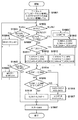
以下、図14のALC部の動作について説明する。ここでは音声をサンプリング周波数Fsでデジタル信号に変換した場合について説明するが、アナログ信号であっても同様である。図15は、図14のALC部の動作を示すフローチャートである。まず、現在時刻がサンプリングタイミングであるか否かを判定し(S1601)、サンプリングタイミングである場合には、音声入力部1501からの音声信号の入力及び音声出力部1503への音声信号の出力を行う(S1602)。次に振幅レベル判定部1509で音声信号の振幅レベル判定を行い(S1603)、ゼロクロス検出部1504で音声信号のゼロクロス検出を行う(S1604)。次にアタック音判定部1510でアタック音の判定を行い(S1605)、振幅ゲイン決定部1506で振幅ゲインを決定(S1606)する。その後、振幅調整部1502で、振幅ゲイン決定部1506の出力であるゲイン1507を用いて音声信号の振幅調整を行い(S1607)、次のサンプルタイミングが来るまで待機する。
Hereinafter, the operation of the ALC unit in FIG. 14 will be described. Here, a case where audio is converted into a digital signal at the sampling frequency Fs will be described, but the same applies to an analog signal. FIG. 15 is a flowchart showing the operation of the ALC unit of FIG. First, it is determined whether or not the current time is the sampling timing (S1601). If it is the sampling timing, the audio signal is input from the
図3は、ゼロクロス検出部1504の動作を示すフローチャートである。まず、音声入力部1501を介して入力された音声信号のサンプル値をDINとする(S301)。DINが、前回のサンプリングタイミングの入力であるDIN_Dと符号が異なる場合、すなわち、DIN>0かつDIN_D<0である場合(S302YES)、ゼロクロス検出結果として、ゼロクロス検出を示す値1を出力する(S305)。また、DIN<0かつDIN_D>0である場合(S303YES)も、ゼロクロス検出を示す値1を出力する(S305)。DINが0である場合も、同様に、ゼロクロス検出結果としてゼロクロス検出を示す値1を出力する(S305)。それ以外の場合はゼロクロス検出結果としてゼロクロス非検出を示す値0を出力する(S305)。こうして得られたゼロクロス検出結果1505は、振幅ゲイン決定部1506に伝達される。そして次の処理のために現在のDINをDIN_Dに代入して(S307)、処理を終了する。
FIG. 3 is a flowchart showing the operation of the zero
図4は、振幅レベル判定部1509の動作を示すフローチャートである。まず、振幅調整部1502から音声出力部1503へと出力される音声サンプルの絶対値をDINとする(S401)。DINが前回の判定結果である振幅レベルDLEVEL以上かどうかを判定する(S402)。DINがDLEVEL以上の場合、DLEVELにDINを代入する(S404)。S402でDINがDLEVEL以上でなければ、DINが前回の判定結果である振幅レベルDLEVELからK1を減じた値以下かどうかを判定する(S403)。その判定がNOであれば、DLEVELにDINを代入する(S404)。その判定がYESであれば、DLEVELからK1を減じた値をDLEVELに代入する(S405)。このときDLEVELがDINより小さくならないように制限する。そして、こうして得たDLEVELを今回の振幅レベル1508として出力する(S406)。以上のようにすることで、音声信号のエンベロープ値が得られるためこれを振幅レベルとする。S401では入力した音声サンプルはそのまま処理してもよいが絶対値をとった方が、正負が非対称の場合でも大きいレベルを反映できるため、ALCの性能が向上する。
FIG. 4 is a flowchart showing the operation of the amplitude
図16は、アタック音判定部1510の動作を示すフローチャートである。振幅調整部1502で振幅を調整する場合に、大きい音声から小さい音声になった場合のゲインの変化量を大きい音声の期間に応じて変えるために、短く大きい音声(アタック音)を判定する。まず、振幅レベル判定部1509で判定された振幅レベル1508をDLEVELとする(S1701)。DLEVELがしきい値TH_MAXより大きい場合(S1702YES)、ATT_CNTに固定値K2を加算する(S1703)。DLEVELがTH_MAXと等しいか小さい場合は(S1702NO)、ATT_CNTが0になるまで(S1704でYESとなるまで)、ATT_CNTから固定値K3を差し引く(S1705)。突然音声が大きくなった場合に、ALCが振幅レベルをTH_MAX以下にするまでATT_CNTがK2ずつ増加し続ける(S1703)。その後振幅レベルがTH_MAX以下であればATT_CNTがK3ずつ減少する(S1705)。したがって、ATT_CNTが0か否かを判定し(S1706)、ここでATT_CNTが0であればアタック音非検出を表す0を出力し(S1707)、ATT_CNTが0でなければアタック音検出を表す1を出力する(S1708)。
FIG. 16 is a flowchart showing the operation of the attack
図17は、振幅ゲイン決定部1506の動作を示すフローチャートである。振幅ゲイン決定部1506では振幅レベル1508がTH_MIN〜TH_MAX(ただしTH_MIN<TH_MAX)の間になるように制御を行う。振幅レベル1508がTH_MINより小さい場合にゲイン1507を増加させる動作の場合をリカバリ動作、振幅レベル1508がTH_MAXより大きい場合にゲイン1507を低下させる動作の場合をリミット動作と呼ぶ。図17のフローチャートにおいて、変数GAINは出力されるゲイン1507を表す。また、S_CNTはサンプル周波数タイミングのカウンタを表す変数である。M_LIMITモードまたはM_RECOVモードの開始時はゼロであり、サンプル周波数タイミング毎にカウントアップする。
FIG. 17 is a flowchart showing the operation of the amplitude
振幅ゲイン決定部1506はまず、ゼロクロス検出結果1505、振幅レベル1508、アタック音判定結果1511をそれぞれ、変数Z_DET、DLEVEL、ATT_DETに入力する(S1801)。その後、モード(MODE)の判定を行いその判定に応じた処理を行う。MODEは、M_IDLE、M_LIMIT、M_RECOVの3つのモードをもつ。リカバリ動作の時はMODE=M_RECOV、リミット動作の時はMODE=M_LIMITとなる。また、振幅レベルがTH_MIN〜TH_MAXの範囲内の場合はMODE=M_IDLEとして、ゲインを保つ。M_LIMIT、M_RECOVは、1サンプル〜複数サンプル期間をかけて処理を行う。
The amplitude
MODE=M_IDLEの場合において、現在の音声の振幅レベルDLEVEL>TH_MAXの場合は(S1803YES)、MODE=M_LIMITに変更し(S1804)、再度、S1802に戻る。一方、DLEVEL<TH_MINの場合は(S1805YES)、MODE=M_RECOVに変更し、再度S1802に戻る。DLEVELがTH_MIN〜TH_MAXの範囲にある場合は(S1803NOかつS1805NO)、GAINの値をそのままゲイン1507として出力して(S1807)、処理を終了する。 In the case of MODE = M_IDLE, if the amplitude level of the current voice DLEVEL> TH_MAX (YES in S1803), the mode is changed to MODE = M_LIMIT (S1804), and the process returns to S1802. On the other hand, if DLEVEL <TH_MIN (YES in S1805), the mode is changed to MODE = M_RECOV, and the process returns to S1802. If DLEVEL is in the range of TH_MIN to TH_MAX (NO in S1803 and S1805), the GAIN value is output as it is as the gain 1507 (S1807), and the process is terminated.
MODE=M_RECOVの場合、リカバリ動作を行うが、DLEVELがTH_MAXを超えた場合は(S1808YES)、MODEをM_LIMITに変更してリミット動作を行う(S1809)。これは、リカバリ動作が終了するまでリミット動作をいっさい行わないとすると音声信号が大きくなりすぎて歪む可能性があるからである。また、MODEをM_RECOVからM_LIMITに変更した場合はS_CNTを0にリセットする(S1809)。 When MODE = M_RECOV, the recovery operation is performed. When DLEVEL exceeds TH_MAX (YES in S1808), the MODE is changed to M_LIMIT and the limit operation is performed (S1809). This is because if the limit operation is not performed until the recovery operation is completed, the audio signal may become too large and distort. If MODE is changed from M_RECOV to M_LIMIT, S_CNT is reset to 0 (S1809).
MODE=M_LIMITの場合、C_MIN、C_MAX、ADD_GAINをそれぞれ、L_C_MAIN、L_C_MAX、L_ADD_GAINに設定する(S1810)。 When MODE = M_LIMIT, C_MIN, C_MAX, and ADD_GAIN are set to L_C_MAIN, L_C_MAX, and L_ADD_GAIN, respectively (S1810).
MODE=M_RECOVの場合で、DLEVELがTH_MAXを超えなければ(S1808NO)、アタック音の検出結果を判定する(S1811)。ここでアタック音未検出(ATT_DET=0)の場合は(S1811NO)、C_MIN、C_MAX、ADD_GAINをそれぞれ、R_C_MAIN、R_C_MAX、R_ADD_GAINに設定する(S1812)。一方、アタック音検出(ATT_DET=1)の場合は(S1811YES)、C_MIN、C_MAX、ADD_GAINをそれぞれ、ATT_C_MAIN、ATT_C_MAX、ATT_ADD_GAINに設定する(S1813)。アタック音検出時のリカバリ動作を「ファーストリカバリ動作」と呼ぶ。C_MINはゲインを変更する最小のサンプル期間を設定するパラメータであり、通常C_MIN<C_MAXの条件で設定するが、ゼロクロス検出結果を使用しない場合、C_MINはどのような値でもかまわない。 If MODE = M_RECOV and DLEVEL does not exceed TH_MAX (NO in S1808), the detection result of the attack sound is determined (S1811). If no attack sound is detected (ATT_DET = 0) (NO in S1811), C_MIN, C_MAX, and ADD_GAIN are set to R_C_MAIN, R_C_MAX, and R_ADD_GAIN, respectively (S1812). On the other hand, in the case of attack sound detection (ATT_DET = 1) (YES in S1811), C_MIN, C_MAX, and ADD_GAIN are set to ATT_C_MAIN, ATT_C_MAX, and ATT_ADD_GAIN, respectively (S1813). The recovery operation at the time of detecting the attack sound is called “first recovery operation”. C_MIN is a parameter for setting the minimum sample period for changing the gain, and is normally set under the condition of C_MIN <C_MAX. However, when the zero cross detection result is not used, C_MIN may be any value.
S_CNT>C_MAXのときは(S1814YES)は、GAINの値を、現在のGAINの値にADD_GAINを加算した値に更新する(S1815)。S_CNT>C_MINかつZ_DET=1(ゼロクロス検出)のとき(S1816YES)も、同様に、GAINの値を、現在のGAINの値にADD_GAINを加算した値に更新する(S1815)。その後、S_CNTを0にリセットするとともに、MODEをM_IDLEにして(S1817)、GAINを出力して(S1807)、処理を終了する。それ以外のときはS_CNTを1インクリメントして(S1818)、MODEを維持したまま、GAINを出力して(S1807)、処理を終了する。 When S_CNT> C_MAX (YES in S1814), the GAIN value is updated to a value obtained by adding ADD_GAIN to the current GAIN value (S1815). Similarly, when S_CNT> C_MIN and Z_DET = 1 (zero cross detection) (YES in S1816), the GAIN value is updated to a value obtained by adding ADD_GAIN to the current GAIN value (S1815). Thereafter, S_CNT is reset to 0, MODE is set to M_IDLE (S1817), GAIN is output (S1807), and the process ends. In other cases, S_CNT is incremented by 1 (S1818), GAIN is output while maintaining MODE (S1807), and the process is terminated.
以上の処理において、C_MINは、GAIN変更の時定数に相当する。C_MINが大きくなるとDLEVELがTH_MIN〜TH_MAXの範囲に収まるまでの時間がかかるようになる。これは、GAIN変更の時定数が大きくなることに相当する。C_MAXは低周波数の音声の場合に、GAIN変更の時定数が大きくなりすぎないようにするリミッタの働きをしている。GAINの変更はGAINにADD_GAINを加算することで行われる(S1815)。従ってM_LIMIT(リミット動作)時、ADD_GAINはマイナス値、M_RECOV(リカバリ動作)時、ADD_GAINはプラス値となる。 In the above processing, C_MIN corresponds to the time constant for changing GAIN. As C_MIN increases, it takes time until DLEVEL falls within the range of TH_MIN to TH_MAX. This corresponds to an increase in the time constant for changing GAIN. C_MAX acts as a limiter to prevent the GAIN change time constant from becoming too large for low frequency audio. GAIN is changed by adding ADD_GAIN to GAIN (S1815). Therefore, ADD_GAIN is a negative value during M_LIMIT (limit operation), and ADD_GAIN is a positive value during M_RECOV (recovery operation).
ゲインの変化分はできるだけ小さくした方が音質に与える影響が少ない。そこで、ここでは以下のようにする。 Making the gain change as small as possible has less effect on the sound quality. Therefore, here is as follows.
R_ADD_GAIN = −L_ADD_GAIN1 = ATT_ADD_GAIN2
なお、R_ADD_GAINは正の値である。リミット動作時は音声信号のレベルが大きくなって歪むので、できるだけ速くゲインを減らした方がよい。一方、リカバリ動作時はレベルの変動が目立たないようにできるだけゲインをゆっくり増加させた方がよい。そこで、
R_C_MIN > L_C_MIN
とする。さらに、アタック音の場合は、リカバリ動作の時定数を小さくして、アタック音直後の音声レベルをできるだけ早く適正レベルにすることが望まれる。そこで、
R_C_MIN > ATT_C_MIN
とする。
R_ADD_GAIN = −L_ADD_GAIN1 = ATT_ADD_GAIN2
R_ADD_GAIN is a positive value. During limit operation, the level of the audio signal increases and distortion occurs, so it is better to reduce the gain as quickly as possible. On the other hand, during the recovery operation, it is better to increase the gain as slowly as possible so that level fluctuations are not noticeable. there,
R_C_MIN> L_C_MIN
And Furthermore, in the case of an attack sound, it is desirable to reduce the time constant of the recovery operation so that the sound level immediately after the attack sound becomes an appropriate level as soon as possible. there,
R_C_MIN> ATT_C_MIN
And
図18において、(a)はアタック音の時のALC動作、(b)はアタック音ではないときのALC動作を示す図である。「入力音エンベロープ」は、音声入力部1501に入力された音声信号のエンベロープ波形であり、(a)は、急に振幅レベルが大きくなりすぐに振幅レベルが小さくなるアタック音を示す。これに対し、(b)は、急に振幅レベルが大きくなるがしばらくしてから振幅レベルが小さくなる、アタック音ではない音声を示す。「出力音エンベロープ」は、音声出力部1503の音声信号のエンベロープ波形であり、ALC実行後の出力である。「ゲイン」は、振幅ゲイン決定部1506で決定されたゲイン1507の変化を示す。「ATT_CNT」は、アタック音判定部1510により図16のフローに従い算出されたATT_CNTの変化を示している。前述したように、アタック音検出時のリカバリ動作を「ファーストリカバリ動作」という。ATT_CNT>0の時にアタック音検出とされるので(S1708)、図18(a)において、T3a〜T4aの期間にファーストリカバリ動作が行われ、T4a〜T5aの期間に通常のリカバリ動作が行われる。(b)においては、T3b〜T4bの期間中はATT_CNT=0であるため、通常のリカバリ動作が行われ、ファーストリカバリ動作は行われない。
In FIG. 18, (a) is an ALC operation at the time of an attack sound, and (b) is a diagram showing an ALC operation at a time when it is not an attack sound. The “input sound envelope” is an envelope waveform of an audio signal input to the
図19は、複数のアタック音が連続的に入力された場合のALC動作を示す図である。図19に示したファーストリカバリ期間ではファーストリカバリ動作が実行されるため、入力が小さくなった場合のゲイン変化の時定数が小さく復帰が早い。このため次のアタック音が来るまでにリカバリ動作が終了しているので、アタック音が連続した場合、複数のアタック音の応答は図示の如く、同じになる。 FIG. 19 is a diagram illustrating an ALC operation when a plurality of attack sounds are continuously input. Since the fast recovery operation is executed in the fast recovery period shown in FIG. 19, the time constant of the gain change when the input becomes small is small and the recovery is quick. For this reason, since the recovery operation is completed before the next attack sound comes, when the attack sounds continue, the responses of the plurality of attack sounds are the same as shown in the figure.
しかし、アタック音が短い周期で連続して入力された場合、1つアタック音でのリカバリ動作において通常よりレベルの増幅率を上げると、それ以降のアタック音の立ち上がり部で音声がクリップして歪んでしまうという問題がある。 However, when attack sounds are input continuously in a short cycle, if the amplification factor of the level is increased in the recovery operation with one attack sound, the sound will be clipped and distorted at the subsequent attack sound rise. There is a problem that it ends up.
そこで以下では、このような問題を解決するための実施形態を説明する。 Therefore, an embodiment for solving such a problem will be described below.
<第1実施形態>
図1は、本実施形態に係る音声処理装置のALC部の構成を示す図である。図1において、音声入力部101は、マイクロホンまたは音声再生装置等からの音声信号を入力する。音声入力部101には、DC成分を除去された音声信号が入力される。従って0を中心に正負の値の音声信号が入力される。本実施形態におけるALC部は、図示の如く、第1のALC機能部11と、その後段に設けられた第2のALC機能部12とを含む。音声出力部105からは、振幅レベルがTH_MIN〜TH_MAX(ただしTH_MIN<TH_MAX)の間になるように調整された音声信号が出力される。
<First Embodiment>
FIG. 1 is a diagram illustrating the configuration of the ALC unit of the speech processing apparatus according to the present embodiment. In FIG. 1, an
第1のレベル制御手段としての第1のALC機能部11は、第1振幅調整部102、第1振幅ゲイン決定部108、第1振幅レベル判定部110を有する。第2のレベル制御手段としての第2のALC機能部12は、第2振幅調整部104、第2振幅ゲイン決定部112、第2振幅レベル判定部114を有する。本実施形態におけるALC部は更に、ゼロクロス検出部106も備える。なお、ゼロクロス検出部106を設けることは音質向上のために有利であるが、必須ではない。
The first
まず、第1のALC機能部11について説明する。第1振幅調整部102は、音声入力部101からの音声信号を第1振幅ゲイン決定部108で決定されたゲイン111に応じて増幅又は減衰させる。第1振幅レベル判定部110は、第1振幅調整部102の出力信号103の振幅レベルを判定する。第1振幅ゲイン決定部108は、第1振幅レベル判定部110で判定された振幅レベル109とゼロクロス検出部106からのゼロクロス検出結果107に応じて、第1振幅調整部102に提供するゲイン111を決定する。
First, the first
第1振幅ゲイン決定部108がゲイン111を変更する場合、音声入力部101からの音声信号の振幅レベルの絶対値が大きいタイミングで変更すると、音声波形に段差ができてしまい、音質が劣化する。そこで本実施形態では、ゼロクロス検出部106で、音声入力部101からの音声信号の振幅レベルが0レベルと交差する点(以下「ゼロクロス」という。)を検出し、第1振幅ゲイン決定部108はそのタイミングでゲイン111を変更する。これにより音質の劣化を少なくすることができる。これは、ゼロクロスのタイミングでは音声信号の振幅レベルの絶対値が小さくなる傾向があることを利用している。ゼロクロス検出結果107は、第1振幅ゲイン決定部108に提供される。第1振幅ゲイン決定部108はそのゼロクロス検出結果107に基づいてゲイン111を変更する。また、第1振幅ゲイン決定部108は、第1振幅レベル判定部110から受信した振幅レベル109がTH_MIN〜TH_MAX(ただしTH_MIN<TH_MAX)の間になるようにゲイン111を制御する。
When the first amplitude
次に、第2のALC機能部12について説明する。第2振幅調整部104は、第1振幅調整部102の出力信号103を第2振幅ゲイン決定部112で決定されたゲイン115に応じて増幅又は減衰させる。第2振幅レベル判定部114は、第2振幅調整部104の出力信号の振幅レベルを判定する。第2振幅ゲイン決定部112は、第2振幅レベル判定部114で判定された振幅レベル113とゼロクロス検出結果107とに基づいて、第2振幅調整部104に提供するゲイン115を決定する。
Next, the second
第1のALC機能部11と同様に、第2振幅ゲイン決定部112は例えば、ゼロクロス検出部106で検出されたゼロクロスのタイミングでゲイン115を変更する。第1振幅調整部102の出力信号103は、音声入力部101に入力された音声信号の振幅が調整されただけであり、出力信号103のゼロクロスのタイミングと音声入力部101に入力された音声信号のゼロクロスのタイミングは同一である。そこで、第1のALC機能部11で使用したゼロクロス検出結果107を活用している。すなわち、ゼロクロス検出結果107は、第2振幅ゲイン決定部112にも伝達される。第2振幅ゲイン決定部112はそのゼロクロス検出結果107に基づいてゲイン115を変更する。また、第2振幅ゲイン決定部112は、第2振幅レベル判定部114から受信した振幅レベル113がTH_MIN〜TH_MAX(ただしTH_MIN<TH_MAX)の間になるようにゲイン115を制御する。
Similar to the first
以下、各部の動作をフローチャート用いて説明する。本実施形態におけるALC部の処理は、デジタル信号処理、アナログ信号処理どちらでも実現可能であるが、ここでは、アナログ音声信号をサンプリング周波数Fsでデジタル信号に変換した場合について説明する。従って、音声入力部101に入力されるのはデジタル化された音声信号であり、音声出力部105からはデジタル音声信号が出力される。
Hereinafter, the operation of each unit will be described with reference to flowcharts. The processing of the ALC unit in this embodiment can be realized by either digital signal processing or analog signal processing. Here, a case where an analog audio signal is converted into a digital signal at the sampling frequency Fs will be described. Accordingly, a digital audio signal is input to the
図2は、図1のALC部の動作を示すフローチャートである。まず、現在時刻がサンプリングタイミングであるか否かを判定し(S201)、サンプリングタイミングである場合には、音声入力部101からの音声信号の入力、及び音声出力部105への音声信号の出力を行う(S202)。次に、第1振幅レベル判定部110及び第2振幅レベル判定部114で振幅レベルの判定を行い(S203)、ゼロクロス検出部106でゼロクロス検出を行う(S204)。次に、第1振幅ゲイン決定部108及び第2振幅ゲイン決定部112で振幅ゲインを決定する(S205)。その後、第1振幅調整部102で、決定されたゲイン111を用いて振幅調整を行うとともに、第2振幅調整部104で、決定されたゲイン115を用いて振幅調整を行い(S206)、次のサンプルタイミングが来るまで待機する。
FIG. 2 is a flowchart showing the operation of the ALC unit of FIG. First, it is determined whether or not the current time is the sampling timing (S201). If the current time is the sampling timing, the input of the audio signal from the
ゼロクロス検出部106の動作は、ゼロクロス検出部1504の動作と同様であり、図3のフローチャートに従い動作する。また、第1及び第2振幅レベル判定部110、114の動作は、振幅レベル判定部1509の動作と同様であり、図4のフローチャートに従い動作する。
The operation of the zero
図5は、第1及び第2振幅調整部102、104の動作を示すフローチャートである。ここでは第1振幅調整部102の動作を説明する。第2振幅調整部104の動作も同様である。まず、入力した音声信号のサンプル値を変数DINとし、ゲイン111を変数GAINに入力する(S501)。次に、DIN*GAINを演算し、その結果を出力する(S502)。GAINがLOGスケールのデシベルである場合は、比率(10^(GAIN/20))に変換する。変換方法はテーブルとシフト演算の組み合わせなど様々な方法があるがどのような方法でもよい。
FIG. 5 is a flowchart showing the operation of the first and second
図6は、第1振幅ゲイン決定部108の動作を示すフローチャートである。第1振幅ゲイン決定部108では振幅レベル109がTH_MIN〜TH_MAX(ただしTH_MIN<TH_MAX)の間になるように制御を行う。上述のように、振幅レベル109がTH_MINより小さい場合にゲイン111を増加させる動作の場合をリカバリ動作、振幅レベル109がTH_MAXより大きい場合にゲイン111を低下させる動作の場合をリミット動作と呼ぶ。図6のフローチャートの中において、変数GAINは出力されるゲイン111を表す。また、S_CNTはサンプル周波数タイミングのカウンタを表す変数である。M_LIMITモードまたはM_RECOVモードの開始時はゼロであり、サンプル周波数タイミング毎にカウントアップする。
FIG. 6 is a flowchart showing the operation of the first amplitude
第1振幅ゲイン決定部108はまず、ゼロクロス検出結果107及び振幅レベル109をそれぞれ、変数Z_DET、DLEVELに入力する(S601)。その後、モード(MODE)の判定を行いその判定に応じた処理を行う。MODEは、M_IDLE、M_LIMIT、M_RECOVの3つのモードをもつ。リカバリ動作の時はMODE=M_RECOV、リミット動作の時はMODE=M_LIMITとなる。また、振幅レベルがTH_MIN〜TH_MAXの範囲内の場合はMODE=M_IDLEとして、ゲインを保つ。M_LIMIT、M_RECOVは、1サンプル〜複数サンプル期間をかけて処理を行う。
First, the first amplitude
MODE=M_IDLEの場合において、現在の音声の振幅レベルDLEVEL>TH_MAXの場合は(S603YES)、MODE=M_LIMITに変更し(S604)、再度、S602に戻る。一方、DLEVEL<TH_MINの場合は(S605YES)、MODE=M_RECOVに変更し、再度、S602に戻る。DLEVELがTH_MIN〜TH_MAXの範囲にある場合は(S603NOかつS605NO)、GAINの値をそのままゲイン111として出力して(S607)、処理を終了する。 If MODE = M_IDLE and the current audio amplitude level DLEVEL> TH_MAX (YES in S603), the mode is changed to MODE = M_LIMIT (S604), and the process returns to S602 again. On the other hand, if DLEVEL <TH_MIN (S605 YES), the mode is changed to MODE = M_RECOV, and the process returns to S602 again. If DLEVEL is in the range of TH_MIN to TH_MAX (S603 NO and S605 NO), the GAIN value is output as it is as the gain 111 (S607), and the process is terminated.
MODE=M_RECOVの場合はリカバリ動作を行うが、DLEVELがTH_MAXを超えた場合は(S608YES)、MODEをM_LIMITに変更してリミット動作を行う(S609)。これは、リカバリ動作が終了するまでリミット動作をいっさい行わないとすると音声信号が大きくなりすぎて歪む可能性があるからである。また、MODEをM_RECOVからM_LIMITに変更した場合はS_CNTを0にリセットする(S609)。 When MODE = M_RECOV, the recovery operation is performed. When DLEVEL exceeds TH_MAX (YES in S608), the MODE is changed to M_LIMIT to perform the limit operation (S609). This is because if the limit operation is not performed until the recovery operation is completed, the audio signal may become too large and distort. When MODE is changed from M_RECOV to M_LIMIT, S_CNT is reset to 0 (S609).
MODE=M_LIMITの場合、C_MIN、C_MAX、ADD_GAINをそれぞれ、L_C_MAIN、L_C_MAX、L_ADD_GAINに設定する(S610)。 When MODE = M_LIMIT, C_MIN, C_MAX, and ADD_GAIN are set to L_C_MAIN, L_C_MAX, and L_ADD_GAIN, respectively (S610).
MODE=M_RECOVの場合で、DLEVELがTH_MAXを超えなければ(S608NO)、C_MIN、C_MAX、ADD_GAINをそれぞれ、R_C_MAIN、R_C_MAX、R_ADD_GAINに設定する(S613)。 If MODEL = M_RECOV and DLEVEL does not exceed TH_MAX (NO in S608), C_MIN, C_MAX, and ADD_GAIN are set to R_C_MAIN, R_C_MAX, and R_ADD_GAIN, respectively (S613).
C_MINはゲインを変更する最小のサンプル期間を設定するパラメータであり、通常C_MIN<C_MAXの条件で設定するが、ゼロクロス検出結果を使用しない場合、C_MINはどのような値でもかまわない。 C_MIN is a parameter for setting the minimum sample period for changing the gain, and is normally set under the condition of C_MIN <C_MAX. However, when the zero cross detection result is not used, C_MIN may be any value.
S_CNT>C_MAXのときは(S614YES)は、GAINの値を、現在のGAINの値にADD_GAINを加算した値に更新する(S615)。S_CNT>C_MINかつZ_DET=1(ゼロクロス検出)のとき(S616YES)も、同様に、GAINの値を、現在のGAINの値にADD_GAINを加算した値に更新する(S615)。その後、S_CNTを0にリセットするとともに、MODEをM_IDLEにして(S617)、処理を終了する。それ以外のときはS_CNTを1インクリメントして(S618)、MODEを維持したまま、GAINを出力して(S607)、処理を終了する。 When S_CNT> C_MAX (YES in S614), the GAIN value is updated to a value obtained by adding ADD_GAIN to the current GAIN value (S615). Similarly, when S_CNT> C_MIN and Z_DET = 1 (zero cross detection) (YES in S616), the GAIN value is updated to a value obtained by adding ADD_GAIN to the current GAIN value (S615). Thereafter, S_CNT is reset to 0, MODE is set to M_IDLE (S617), and the process is terminated. Otherwise, S_CNT is incremented by 1 (S618), GAIN is output while maintaining MODE (S607), and the process is terminated.
以上の処理において、C_MINは、GAIN変更の時定数に相当する。C_MINが大きくなるとDLEVELがTH_MIN〜TH_MAXの範囲に収まるまでの時間がかかるようになる。これは、GAIN変更の時定数が大きくなることに相当する。C_MAXは低周波数の音声の場合に、GAIN変更の時定数が大きくなりすぎないようにするリミッタの働きをしている。GAINの変更はGAINにADD_GAINを加算することで行われる(S615)。従ってM_LIMIT(リミット動作)時、ADD_GAINはマイナス値、M_RECOV(リカバリ動作)時、ADD_GAINはプラス値となる。 In the above processing, C_MIN corresponds to the time constant for changing GAIN. As C_MIN increases, it takes time until DLEVEL falls within the range of TH_MIN to TH_MAX. This corresponds to an increase in the time constant for changing GAIN. C_MAX acts as a limiter to prevent the GAIN change time constant from becoming too large for low frequency audio. GAIN is changed by adding ADD_GAIN to GAIN (S615). Therefore, ADD_GAIN is a negative value during M_LIMIT (limit operation), and ADD_GAIN is a positive value during M_RECOV (recovery operation).
以上が、第1振幅ゲイン決定部108の動作フローである。第2振幅ゲイン決定部112の動作フローも第1振幅ゲイン決定部108と同様である。
The operation flow of the first amplitude
ただし、R_C_MIN、R_C_MAX、R_ADD_GAIN、L_C_MIN、L_C_MAX、L_ADD_GAINは、第1のALC機能部11と第2のALC機能部12との間で異なる値に設定する。ここで、第1のALC機能部11側の値を、R_C_MIN1、R_C_MAX1、R_ADD_GAIN1、L_C_MIN1、L_C_MAX1、L_ADD_GAIN1とする。一方、第2のALC機能部12側の値を、R_C_MIN2、R_C_MAX2、R_ADD_GAIN2、L_C_MIN2、L_C_MAX2、L_ADD_GAIN2とする。この場合に、例えば以下のような設定とすることで、アタック音が連続した場合でも良好なALC動作を実現できる。
However, R_C_MIN, R_C_MAX, R_ADD_GAIN, L_C_MIN, L_C_MAX, and L_ADD_GAIN are set to different values between the first
ゲインの変化分はできるだけ小さくした方が音質に与える影響が少ないため、本実施形態では、
R_ADD_GAIN1 = −L_ADD_GAIN1 = R_ADD_GAIN2 = −L_ADD_GAIN2
とする。なお、R_ADD_GAIN1は正の値である。
Since the change in gain is as small as possible has less effect on sound quality, in this embodiment,
R_ADD_GAIN1 = −L_ADD_GAIN1 = R_ADD_GAIN2 = −L_ADD_GAIN2
And R_ADD_GAIN1 is a positive value.
リミット動作時は、音声信号のレベルが大きくなって歪むので、できるだけ速くゲインを減らした方がよい。一方、リカバリ動作時はレベルの変動が目立たないようにできるだけゲインをゆっくり増加させた方がよいそこで、
R_C_MIN1 > L_C_MIN1、
R_C_MIN2 > L_C_MIN2
とする。
During the limit operation, the audio signal level increases and distortion occurs, so it is better to reduce the gain as quickly as possible. On the other hand, at the time of recovery operation, it is better to increase the gain as slowly as possible so that the level fluctuation is not noticeable,
R_C_MIN1> L_C_MIN1,
R_C_MIN2> L_C_MIN2
And
また、第1のALC機能部11のリカバリ動作時のゲイン増加の時定数を、第2のALC機能部12のゲイン増加の時定数より大きくすることで、アタック音が連続した場合に良好な特性を得ることができる。従って以下のような関係を設定する。
Further, by making the time constant of gain increase during the recovery operation of the first
R_C_MIN1 > R_C_MIN2
リミット動作時におけるゲイン変化については、設定値によって動作が変わるが、概ね以下の関係にあれば問題はない。(L_C_MIN1 < L_C_MIN2でもかまわない。)
L_C_MIN1 ≧ L_C_MIN2
ゼロクロス検出を行わない場合は、
R_C_MIN1=R_C_MAX1、
L_C_MIN1=L_C_MAX1、
R_C_MIN2=R_C_MAX2、
L_C_MIN2=L_C_MAX2
とする。これにより、Z_DETに関係なく動作する。
R_C_MIN1> R_C_MIN2
Regarding the gain change during the limit operation, the operation varies depending on the set value, but there is no problem as long as the relationship is generally as follows. (L_C_MIN1 <L_C_MIN2 may also be used.)
L_C_MIN1 ≧ L_C_MIN2
When zero cross detection is not performed,
R_C_MIN1 = R_C_MAX1,
L_C_MIN1 = L_C_MAX1,
R_C_MIN2 = R_C_MAX2,
L_C_MIN2 = L_C_MAX2
And Thereby, it operates regardless of Z_DET.
本実施形態において、
L_C_MIN1 > L_C_MIN2
とした場合に、複数のアタック音が連続的に入力された場合の動作を図7に示す。図7において、「入力音エンベロープ」は、音声入力部101に入力された音声信号のエンベロープ波形であり、複数のアタック音が連続して入力されている。「出力音エンベロープ」は、音声出力部105に出力される音声信号のエンベロープ波形であり、本実施形態のALC実行後の音声信号のエンベロープ波形である。「ゲイン1」は、第1振幅ゲイン決定部108で決定されたゲイン111の変化を示し、「ゲイン2」は、第2振幅ゲイン決定部112で決定されたゲイン115の変化を示している。「合計ゲイン」は、ゲイン1とゲイン2との合計値であり、ALC部全体のゲインに相当する。
In this embodiment,
L_C_MIN1> L_C_MIN2
FIG. 7 shows the operation when a plurality of attack sounds are continuously input. In FIG. 7, “input sound envelope” is an envelope waveform of an audio signal input to the
R_C_MIN1>R_C_MIN2であるため、アタック音が連続した場合にゲイン1が減少していき、応答の速い第2のALC機能部12側のゲイン2の値は、入力音エンベロープの振幅が急に大きくなる部分で変更される割合が減っていく。このため、アタック音が連続した場合に、アタック音の突入部分での出力音声の歪みを抑制することができる。なお、アタック音が1回だけであった場合は、第2のALC機能部12側の速い時定数によってリカバリが行われるので、従来と同等の特性を得ることができる。
Since R_C_MIN1> R_C_MIN2, the
<第2実施形態>
図8は、第2実施形態に係る音声処理装置のALC部の構成を示す図である。図8において、音声入力部801は、マイクロホンまたは音声再生装置等からの音声信号を入力する。音声入力部801には、DC成分を除去された音声信号が入力される。従って0を中心に正負の値の音声信号が入力される。音声出力部803からは、振幅レベルがTH_MIN〜TH_MAX(ただしTH_MIN<TH_MAX)の間になるように調整された音声信号が出力される。
Second Embodiment
FIG. 8 is a diagram illustrating the configuration of the ALC unit of the speech processing apparatus according to the second embodiment. In FIG. 8, a
本実施形態は、第1実施形態と等価な動作を提供するものである。本実施形態におけるALC部は、振幅レベル判定部804、振幅調整部802、ゼロクロス検出部810、第1及び第2振幅ゲイン決定部812,814を含む。本実施形態におけるALC部は更に、第1の予測手段としての第1振幅レベル予測部806、第2の予測手段としての第2振幅レベル予測部808、振幅ゲイン演算部816を含む。
This embodiment provides an operation equivalent to that of the first embodiment. The ALC unit in the present embodiment includes an amplitude level determination unit 804, an
図9は、図8のALC部の動作を示すフローチャートである。まず、現在時刻がサンプリングタイミングであるか否かを判定し(S901)、サンプリングタイミングである場合には、音声入力部801からの音声信号の入力、及び音声出力部803への音声信号の出力を行う(S902)。次に、振幅レベル判定部804で振幅レベルの判定を行い(S903)、ゼロクロス検出部810でゼロクロス検出を行う(S904)。次に、第1振幅レベル予測部806で振幅レベル予測を行った後、更に第2振幅レベル予測部808で振幅レベル予測を行う(S905)。次に、第1のゲイン制御手段としての第1振幅ゲイン決定部812及び第2のゲイン制御手段としての第2振幅ゲイン決定部814で振幅ゲインを決定する(S906)。その後、振幅ゲイン演算部816で、第1振幅ゲイン決定部812で決定された第1ゲイン813と、第2振幅ゲイン決定部814で決定された第2ゲイン815とを加算する(S907)。そして、振幅調整部802で、加算結果である合計ゲイン817を用いて振幅調整を行い(S908)、次のサンプルタイミングが来るまで待機する。
FIG. 9 is a flowchart showing the operation of the ALC unit of FIG. First, it is determined whether or not the current time is the sampling timing (S901). If it is the sampling timing, the input of the audio signal from the
ゼロクロス検出部810の動作は、ゼロクロス検出部1504の動作と同様であり、図3のフローチャートに従い動作する。また、振幅レベル判定部804の動作は、振幅レベル判定部1509の動作と同様であり、図4のフローチャートに従い動作する。振幅調整部802の動作は、第1実施形態における第1及び第2振幅調整部102、104の動作と同様であり、図5のフローチャートに従い動作する。第1及び第2振幅ゲイン決定部812,814の動作は、第1及び第2振幅ゲイン決定部108,112の動作と同様であり、図6のフローチャートに従い動作する。
The operation of the zero
R_C_MIN、R_C_MAX、R_ADD_GAIN、L_C_MIN、L_C_MAX、L_ADD_GAINは、第1振幅ゲイン決定部812と第2振幅ゲイン決定部814との間で異なる値に設定する。ここで、第1振幅ゲイン決定部812側の値を、R_C_MIN1、R_C_MAX1、R_ADD_GAIN1、L_C_MIN1、L_C_MAX1、L_ADD_GAIN1とする。一方、第2振幅ゲイン決定部814側の値を、R_C_MIN2、R_C_MAX2、R_ADD_GAIN2、L_C_MIN2、L_C_MAX2、L_ADD_GAIN2とする。これらの値を第1実施形態と同様にすることで、第1実施形態と同様にアタック音が連続した場合でも良好なALC動作を実現できる。
R_C_MIN, R_C_MAX, R_ADD_GAIN, L_C_MIN, L_C_MAX, and L_ADD_GAIN are set to different values between the first amplitude
<第3実施形態>
上述の第2実施形態において、合計ゲイン817は、図7の期間1〜4では一定であることが望ましい。しかし、ゲイン1とゲイン2は独立に動作しているため、合計ゲインがゲイン可変幅の最小単位で変動する可能性がある。本実施形態は、その対策を施すものである。
<Third Embodiment>
In the second embodiment described above, the
図10は、第3実施形態における音声処理装置のALC部の構成を示す図である。図10の構成は、図8の構成に対して、第1振幅ゲイン決定部812で決定されたゲインを調整する振幅ゲイン調整部850が付加された構成となっている。図8の構成要素と同一の構成要素については共通の参照符号を付し、それらの説明は省略する。ただし、第2振幅ゲイン決定部814は、振幅ゲイン調整部850で調整されたゲインに基づいてゲインを決定する構成となっている。
FIG. 10 is a diagram illustrating the configuration of the ALC unit of the speech processing apparatus according to the third embodiment. The configuration of FIG. 10 is a configuration in which an amplitude
図11は、図10のALC部の動作を示すフローチャートである。図9のフローチャートにおけるステップと同一のステップについては共通の参照符号を付し、それらの説明は省略する。図11において、図10との違いは、S906の代わりにS1101が実行される点である。S1101では、まず、第1振幅ゲイン決定部812が振幅ゲインを決定する。次に、振幅ゲイン調整部850が、後述する図12のフローに従う動作により、その決定された振幅ゲインを調整する。その後、第2振幅ゲイン決定部814でその調整結果を用いて振幅ゲインを決定する。
FIG. 11 is a flowchart showing the operation of the ALC unit of FIG. Steps that are the same as the steps in the flowchart of FIG. 9 are given common reference numerals, and descriptions thereof are omitted. In FIG. 11, the difference from FIG. 10 is that S1101 is executed instead of S906. In S1101, first, the first amplitude
図12は、振幅ゲイン調整部850の動作を示すフローチャートである。まず、第1振幅レベル予測部806で予測された振幅レベルを変数DINに入力し、第1振幅ゲイン決定部812で決定されたゲイン813を変数GAINに入力する(S1201)。DINの値が、TH_MIN〜TH_MAX(ただしTH_MIN<TH_MAX)の間の場合(S1202,S1203ともにNOの場合)、変数ADJ_GAINにGAIN_D−GAINを代入する(S1204)。そうでなければ、変数ADJ_GAINに0を代入する(S1205)。GAIN_Dは前回のサンプルタイミングで入力されたゲイン813である。次のサンプリングタイミングの処理のためにGAIN_DにGAINを代入する(S1206)。そして、ADJ_GAINを第2振幅ゲイン決定部814に出力する(S1207)。
FIG. 12 is a flowchart showing the operation of the amplitude
図13は、第2振幅ゲイン決定部814の動作を示すフローチャートである。図6のフローチャートにおけるステップと同一のステップについては共通の参照符号を付し、それらの説明は省略する。図13において、図6との違いは、S601の代わりにS1301が実行される点、及び、S607の代わりにS1302が実行される点である。S1301では、ゼロクロス検出部810でのゼロクロス検出結果を変数Z_DETに入力し、振幅レベル判定部804で判定された振幅レベルを変数DLEVELに入力する。更に、振幅ゲイン調整部850で調整された振幅ゲイン(調整ゲイン)を変数ADV_GAINに入力する。また、S1302では、現在のGAINにADJ_GAINを加算した値を新たなGAINに更新し、その更新後のGAINを出力する。
FIG. 13 is a flowchart showing the operation of the second amplitude
第3実施形態によれば、第2振幅レベル予測部808で予測された振幅レベルがTH_MIN〜TH_MAXの範囲にある場合、第1振幅ゲイン決定部812で決定されたゲインが変化すると、その変化分が振幅ゲイン調整部850で調整される。この調整により、ゲイン1+ゲイン2が変化しない。これにより図7の期間1〜4でゲイン可変幅の最小単位での変動を抑制することができる。
According to the third embodiment, when the amplitude level predicted by the second amplitude
<他の実施形態>
また、本発明は、以下の処理を実行することによっても実現される。即ち、上述した実施形態の機能を実現するソフトウェア(プログラム)を、ネットワーク又は各種記憶媒体を介してシステム或いは装置に供給し、そのシステム或いは装置のコンピュータ(またはCPUやMPU等)がプログラムを読み出して実行する処理である。この場合、そのプログラム、及び該プログラムを記憶した記憶媒体は本発明を構成することになる。
<Other embodiments>
The present invention can also be realized by executing the following processing. That is, software (program) that realizes the functions of the above-described embodiments is supplied to a system or apparatus via a network or various storage media, and a computer (or CPU, MPU, or the like) of the system or apparatus reads the program. It is a process to be executed. In this case, the program and the storage medium storing the program constitute the present invention.
Claims (9)
前記第1のレベル制御手段からの音声信号の振幅レベルを、ゲインを用いて調整する第2のレベル制御手段であって、前記第2のレベル制御手段からの音声信号の振幅レベルが前記所定範囲の上限値を超えた場合はゲインを低下させるリミット動作を行い、前記第2のレベル制御手段からの音声信号の振幅レベルが前記所定範囲の下限値より小さい場合はゲインを増加させるリカバリ動作を行う、第2のレベル制御手段と、を有し、
前記第1のレベル制御手段でのリカバリ動作時のゲインの増加の時定数を、前記第2のレベル制御手段でのリカバリ動作時のゲインの増加の時定数より大きくすることを特徴とする音声処理装置。 The amplitude level of the input audio signal, a first level control means for adjusting using the gain, the amplitude level of the audio signal from said first level control means exceeds the upper limit of the predetermined range If performs limit operation to lower the gain, when the amplitude level of the audio signal from said first level control means is smaller than the lower limit of the predetermined range to recover operation to increase the gain, the first Level control means;
Second level control means for adjusting the amplitude level of the audio signal from the first level control means using a gain , wherein the amplitude level of the audio signal from the second level control means is within the predetermined range. When the upper limit value is exceeded, a limit operation is performed to reduce the gain. When the amplitude level of the audio signal from the second level control means is smaller than the lower limit value of the predetermined range, a recovery operation is performed to increase the gain And second level control means,
The time constant of increase in gain at the time of recovery operation in the first level control means, characterized by greater than the time constant of the increase in the gain during the recovery operation in the second level control means Audio processing device.
前記第1のレベル制御手段及び前記第2のレベル制御手段はそれぞれ、前記ゼロクロスが検出されたタイミングで前記ゲインを変化させることを特徴とする請求項1に記載の音声処理装置。 A zero cross detecting means for detecting a zero cross where the amplitude level of the input audio signal crosses the zero level;
Audio processing apparatus of claim 1, wherein each said first level control means and the second level control means, said zero crossing and wherein the varying the gain in detected timing.
入力された音声信号の振幅レベルを判定する判定手段と、
前記判定された振幅レベルに第1ゲインを乗じて得た振幅レベルを予測する第1の予測手段と、
前記第1の予測手段で予測された振幅レベルに第2ゲインを乗じて得た振幅レベルを予測する第2の予測手段と、
前記第1の予測手段で予測された振幅レベルが前記所定範囲の上限値を超えた場合は前記第1ゲインを低下させるリミット動作を行い、前記第1の予測手段で予測された振幅レベルが前記所定範囲の下限値より小さい場合は前記第1ゲインを増加させるリカバリ動作を行う、第1のゲイン制御手段と、
前記第2の予測手段で予測された振幅レベルが前記所定範囲の上限値を超えた場合は前記第2ゲインを低下させるリミット動作を行い、前記第2の予測手段で予測された振幅レベルが前記所定範囲の下限値より小さい場合は前記第2ゲインを増加させるリカバリ動作を行う、第2のゲイン制御手段と、
前記第1のゲイン制御手段により制御された前記第1ゲインと前記第2のゲイン制御手段により制御された前記第2ゲインとを合計した合計ゲインにより、前記入力された音声信号の振幅レベルを調整する調整手段と、を有し、
前記第1のゲイン制御手段でのリカバリ動作時の前記第1ゲインの増加の時定数を、前記第2のゲイン制御手段でのリカバリ動作時の前記第2ゲインの増加の時定数より大きくすることを特徴とする音声処理装置。 An audio processing device that adjusts the amplitude level so that the amplitude level of an input audio signal is within a predetermined range,
Determining means for determining the amplitude level of the input audio signal;
First prediction means for predicting an amplitude level obtained by multiplying the determined amplitude level by a first gain;
Second prediction means for predicting an amplitude level obtained by multiplying the amplitude level predicted by the first prediction means by a second gain;
When the amplitude level predicted by the first prediction means exceeds the upper limit value of the predetermined range, a limit operation is performed to reduce the first gain, and the amplitude level predicted by the first prediction means is A first gain control means for performing a recovery operation for increasing the first gain when it is smaller than a lower limit value of a predetermined range;
When the amplitude level predicted by the second prediction means exceeds the upper limit value of the predetermined range, a limit operation is performed to reduce the second gain , and the amplitude level predicted by the second prediction means is A second gain control means for performing a recovery operation to increase the second gain when it is smaller than a lower limit value of a predetermined range ;
The amplitude level of the input audio signal is adjusted by a total gain obtained by summing the first gain controlled by the first gain control means and the second gain controlled by the second gain control means. Adjusting means to perform,
The time constant for increasing the first gain during the recovery operation by the first gain control means is made larger than the time constant for increasing the second gain during the recovery operation by the second gain control means. A voice processing apparatus characterized by the above.
前記第1のゲイン制御手段及び前記第2のゲイン制御手段はそれぞれ、前記ゼロクロスが検出されたタイミングで前記第1ゲイン及び前記第2ゲインを変化させることを特徴とする請求項4又は5に記載の音声処理装置。 A zero cross detecting means for detecting a zero cross where the amplitude level of the input audio signal crosses a zero level;
According to claim 4 or 5, characterized in that changing the first gain control means and said second respective gain control means, said first gain and said second gain at a timing at which the zero crossing has been detected Voice processing device.
第2のレベル制御手段が、前記第1のレベル制御手段からの音声信号の振幅レベルを、ゲインを用いて調整する第2のレベル制御ステップであって、前記第2のレベル制御手段からの音声信号の振幅レベルが前記所定範囲の上限値を超えた場合はゲインを低下させるリミット動作を行い、前記第2のレベル制御手段からの音声信号の振幅レベルが前記所定範囲の下限値より小さい場合はゲインを増加させるリカバリ動作を行う、第2のレベル制御ステップと、を有し、
前記第1のレベル制御ステップでのリカバリ動作時のゲインの増加の時定数を、前記第2のレベル制御ステップでのリカバリ動作時のゲインの増加の時定数より大きくすることを特徴とする音声処理装置の制御方法。 The first level control means is a first level control step for adjusting the amplitude level of the input audio signal using a gain, and the amplitude level of the audio signal from the first level control means is predetermined. If it exceeds the upper limit of the range subjected to limit operation to lower the gain, recovery amplitude level of the audio signal from said first level control means for increasing the gain is smaller than the lower limit of the predetermined range A first level control step for performing an operation;
The second level control means is a second level control step in which the amplitude level of the audio signal from the first level control means is adjusted using a gain, and the audio from the second level control means When the amplitude level of the signal exceeds the upper limit value of the predetermined range, a limit operation is performed to reduce the gain. When the amplitude level of the audio signal from the second level control means is smaller than the lower limit value of the predetermined range, A second level control step for performing a recovery operation to increase the gain , and
The time constant of increase the recovery operation when the gain in the first level control step, characterized by greater than the time constant of the gain increase during recovery operation in the second-level control step A method for controlling a speech processing apparatus.
判定手段が、入力された音声信号の振幅レベルを判定する判定ステップと、
第1の予測手段が、前記判定された振幅レベルに第1ゲインを乗じて得た振幅レベルを予測する第1の予測ステップと、
第2の予測手段が、前記第1の予測ステップで予測された振幅レベルに第2ゲインを乗じて得た振幅レベルを予測する第2の予測ステップと、
第1のゲイン制御手段が、前記第1の予測ステップで予測された振幅レベルが前記所定範囲の上限値を超えた場合は前記第1ゲインを低下させるリミット動作を行い、前記第1の予測ステップで予測された振幅レベルが前記所定範囲の下限値より小さい場合は前記第1ゲインを増加させるリカバリ動作を行う、第1のゲイン制御ステップと、
第2のゲイン制御手段が、前記第2の予測ステップで予測された振幅レベルが前記所定範囲の上限値を超えた場合は前記第2ゲインを低下させるリミット動作を行い、前記第2の予測ステップで予測された振幅レベルが前記所定範囲の下限値より小さい場合は前記第2ゲインを増加させるリカバリ動作を行う、第2のゲイン制御ステップと、
調整手段が、前記第1のゲイン制御ステップで制御された前記第1ゲインと前記第2のゲイン制御ステップで制御された前記第2ゲインとを合計した合計ゲインにより、前記入力された音声信号の振幅レベルを調整する調整ステップと、を有し、
前記第1のゲイン制御ステップでのリカバリ動作時の前記第1ゲインの増加の時定数を、前記第2のゲイン制御ステップでのリカバリ動作時の前記第2ゲインの増加の時定数より大きくすることを特徴とする音声処理装置の制御方法。 A method for controlling a speech processing apparatus that adjusts the amplitude level so that the amplitude level of an input speech signal falls within a predetermined range,
A determining step for determining an amplitude level of the input audio signal;
A first prediction step, wherein a first prediction means predicts an amplitude level obtained by multiplying the determined amplitude level by a first gain;
A second prediction step, wherein the second prediction means predicts an amplitude level obtained by multiplying the amplitude level predicted in the first prediction step by a second gain;
The first gain control means performs a limit operation to reduce the first gain when the amplitude level predicted in the first prediction step exceeds the upper limit value of the predetermined range, and the first prediction step. A first gain control step for performing a recovery operation to increase the first gain when the amplitude level predicted in step (b) is smaller than a lower limit value of the predetermined range;
The second gain control means performs a limit operation to reduce the second gain when the amplitude level predicted in the second prediction step exceeds the upper limit value of the predetermined range , and the second prediction step. A second gain control step for performing a recovery operation for increasing the second gain when the amplitude level predicted in step (b) is smaller than a lower limit value of the predetermined range ;
The adjusting means uses the total gain obtained by summing the first gain controlled in the first gain control step and the second gain controlled in the second gain control step, to adjust the input audio signal. An adjusting step for adjusting the amplitude level,
The time constant for increasing the first gain during the recovery operation in the first gain control step is made larger than the time constant for increasing the second gain during the recovery operation in the second gain control step. A method for controlling a speech processing apparatus.
Priority Applications (3)
| Application Number | Priority Date | Filing Date | Title |
|---|---|---|---|
| JP2012286160A JP6105929B2 (en) | 2012-12-27 | 2012-12-27 | Speech processing apparatus and control method thereof |
| US14/139,058 US9319015B2 (en) | 2012-12-27 | 2013-12-23 | Audio processing apparatus and method |
| CN201310741393.7A CN103905008B (en) | 2012-12-27 | 2013-12-27 | Audio processing equipment and audio-frequency processing method |
Applications Claiming Priority (1)
| Application Number | Priority Date | Filing Date | Title |
|---|---|---|---|
| JP2012286160A JP6105929B2 (en) | 2012-12-27 | 2012-12-27 | Speech processing apparatus and control method thereof |
Publications (3)
| Publication Number | Publication Date |
|---|---|
| JP2014126854A JP2014126854A (en) | 2014-07-07 |
| JP2014126854A5 JP2014126854A5 (en) | 2016-02-18 |
| JP6105929B2 true JP6105929B2 (en) | 2017-03-29 |
Family
ID=50996186
Family Applications (1)
| Application Number | Title | Priority Date | Filing Date |
|---|---|---|---|
| JP2012286160A Active JP6105929B2 (en) | 2012-12-27 | 2012-12-27 | Speech processing apparatus and control method thereof |
Country Status (3)
| Country | Link |
|---|---|
| US (1) | US9319015B2 (en) |
| JP (1) | JP6105929B2 (en) |
| CN (1) | CN103905008B (en) |
Families Citing this family (12)
| Publication number | Priority date | Publication date | Assignee | Title |
|---|---|---|---|---|
| JP2015130547A (en) * | 2014-01-06 | 2015-07-16 | パナソニックIpマネジメント株式会社 | Recorder |
| WO2016179647A1 (en) * | 2015-05-08 | 2016-11-17 | Barratt Lachlan | Normalised attack in digital signal processing |
| EP3133736A1 (en) * | 2015-08-17 | 2017-02-22 | Nxp B.V. | Gain control apparatus |
| WO2017047000A1 (en) | 2015-09-14 | 2017-03-23 | パナソニックIpマネジメント株式会社 | Sound signal processing apparatus and image pickup apparatus using same |
| CN106504765B (en) * | 2016-10-20 | 2019-08-13 | 广州视源电子科技股份有限公司 | Automatic gain control method and device for audio signal |
| JP2019062514A (en) * | 2016-12-26 | 2019-04-18 | キヤノン株式会社 | Audio processing apparatus and method of controlling same |
| JP6878137B2 (en) | 2017-05-19 | 2021-05-26 | キヤノン株式会社 | Audio processor, audio processing method and program |
| JP6570577B2 (en) * | 2017-05-19 | 2019-09-04 | キヤノン株式会社 | Audio processing apparatus, audio processing method, and program |
| JP6887315B2 (en) * | 2017-06-05 | 2021-06-16 | キヤノン株式会社 | Speech processing device and its control method, program and storage medium |
| WO2019033440A1 (en) * | 2017-08-18 | 2019-02-21 | 广东欧珀移动通信有限公司 | Volume adjustment method and apparatus, terminal device, and storage medium |
| CN114915275A (en) * | 2021-02-08 | 2022-08-16 | 祖玛视频通讯公司 | Two-stage digital automatic gain control |
| CN113872529A (en) * | 2021-10-09 | 2021-12-31 | 深圳市创成微电子有限公司 | Audio equipment and control method of amplifier power supply voltage thereof |
Family Cites Families (24)
| Publication number | Priority date | Publication date | Assignee | Title |
|---|---|---|---|---|
| KR100286006B1 (en) * | 1993-03-31 | 2001-04-16 | 윤종용 | Automatic gain controller |
| JPH07193446A (en) * | 1993-12-24 | 1995-07-28 | Nec Corp | Automatic predictive gain switching circuit |
| JPH08274558A (en) * | 1995-03-28 | 1996-10-18 | Kokusai Electric Co Ltd | Agc circuit for mobile communication equipment |
| JPH09258782A (en) * | 1996-03-08 | 1997-10-03 | Sony United Kingdom Ltd | Digital voice processor |
| US6535846B1 (en) * | 1997-03-19 | 2003-03-18 | K.S. Waves Ltd. | Dynamic range compressor-limiter and low-level expander with look-ahead for maximizing and stabilizing voice level in telecommunication applications |
| US7058188B1 (en) * | 1999-10-19 | 2006-06-06 | Texas Instruments Incorporated | Configurable digital loudness compensation system and method |
| JP2001298340A (en) * | 2000-04-17 | 2001-10-26 | Sanyo Electric Co Ltd | Automatic level control circuit |
| US7248702B2 (en) * | 2003-01-06 | 2007-07-24 | Thomas Nelson Packard | Sound enhancement system |
| US7353169B1 (en) * | 2003-06-24 | 2008-04-01 | Creative Technology Ltd. | Transient detection and modification in audio signals |
| JP4578169B2 (en) * | 2004-07-23 | 2010-11-10 | 三洋電機株式会社 | Automatic level adjustment circuit |
| CN100581052C (en) * | 2004-08-13 | 2010-01-13 | 深圳赛意法微电子有限公司 | Automatic gain control system with self-adaptive climb and decay time |
| US8290181B2 (en) * | 2005-03-19 | 2012-10-16 | Microsoft Corporation | Automatic audio gain control for concurrent capture applications |
| US8488811B2 (en) * | 2006-08-09 | 2013-07-16 | Dolby Laboratories Licensing Corporation | Audio-peak limiting in slow and fast stages |
| JP4123486B2 (en) * | 2006-10-02 | 2008-07-23 | 日本ビクター株式会社 | Digital audio processing method, digital audio processing apparatus, and computer program |
| JP2008129107A (en) | 2006-11-17 | 2008-06-05 | Sanyo Electric Co Ltd | Automatic gain control device, audio recording device, video/audio recording device and telephone call device |
| EP1923994B1 (en) * | 2006-11-17 | 2008-11-19 | AKG Acoustics GmbH | Audio compressor |
| GB2455742B (en) * | 2007-12-19 | 2011-11-02 | Wolfson Microelectronics Plc | Dynamic range controller |
| AU2009313780A1 (en) * | 2008-11-14 | 2010-05-20 | That Corporation | Dynamic volume control and multi-spatial processing protection |
| JP5394905B2 (en) * | 2009-01-14 | 2014-01-22 | ローム株式会社 | Automatic level control circuit, audio digital signal processor and variable gain amplifier gain control method using the same |
| JP5120288B2 (en) | 2009-02-16 | 2013-01-16 | ソニー株式会社 | Volume correction device, volume correction method, volume correction program, and electronic device |
| JP5556673B2 (en) * | 2011-01-11 | 2014-07-23 | 株式会社Jvcケンウッド | Audio signal correction apparatus, audio signal correction method and program |
| EP2512157B1 (en) | 2011-04-13 | 2013-11-20 | Oticon A/s | Hearing device with automatic clipping prevention and corresponding method |
| US8582786B2 (en) | 2011-06-15 | 2013-11-12 | Alpine Electronics, Inc. | Automatic gain control of amplifier by dynamic suppressing and output control at multiple stages |
| CN202334444U (en) | 2011-10-31 | 2012-07-11 | 四川和芯微电子股份有限公司 | Adjustable-gain audio power amplifying circuit |
-
2012
- 2012-12-27 JP JP2012286160A patent/JP6105929B2/en active Active
-
2013
- 2013-12-23 US US14/139,058 patent/US9319015B2/en not_active Expired - Fee Related
- 2013-12-27 CN CN201310741393.7A patent/CN103905008B/en active Active
Also Published As
| Publication number | Publication date |
|---|---|
| JP2014126854A (en) | 2014-07-07 |
| US9319015B2 (en) | 2016-04-19 |
| US20140185833A1 (en) | 2014-07-03 |
| CN103905008A (en) | 2014-07-02 |
| CN103905008B (en) | 2017-03-01 |
Similar Documents
| Publication | Publication Date | Title |
|---|---|---|
| JP6105929B2 (en) | Speech processing apparatus and control method thereof | |
| US9064497B2 (en) | Method and apparatus for audio intelligibility enhancement and computing apparatus | |
| US9614489B2 (en) | Sound producing system and audio amplifying method thereof | |
| WO2010131470A1 (en) | Gain control apparatus and gain control method, and voice output apparatus | |
| JP5381982B2 (en) | Voice detection device, voice detection method, voice detection program, and recording medium | |
| US10200000B2 (en) | Handheld electronic apparatus, sound producing system and control method of sound producing thereof | |
| US20110051953A1 (en) | Calibrating multiple microphones | |
| JP6011880B2 (en) | Howling suppression device, hearing aid, howling suppression method, and integrated circuit | |
| US8600078B2 (en) | Audio signal amplitude adjusting device and method | |
| US20230164480A1 (en) | Audio processing method and electronic device | |
| CN102610232B (en) | Method for adjusting self-adaptive audio sensing loudness | |
| JP5975290B2 (en) | Howling suppression device, hearing aid, howling suppression method, and integrated circuit | |
| JP2011150060A (en) | Recording device | |
| JPWO2006093256A1 (en) | Audio reproduction apparatus and method, and computer program | |
| JP5147420B2 (en) | Amplifier circuit | |
| JP5762797B2 (en) | Signal processing apparatus and signal processing method | |
| JP4814861B2 (en) | Volume control apparatus, method, and program | |
| JP6887315B2 (en) | Speech processing device and its control method, program and storage medium | |
| US20180183399A1 (en) | Audio processing apparatus and method of controlling same | |
| JP5857216B2 (en) | Automatic gain controller | |
| US20230262389A1 (en) | Acoustic processing device and acoustic processing method | |
| US9407231B2 (en) | Apparatus and method of multi-sensor sound recording | |
| JP5346350B2 (en) | Echo canceling apparatus, method and program | |
| JP2006279157A (en) | Howling suppression system | |
| CN117499838A (en) | Audio processing method and device and non-volatile computer readable storage medium |
Legal Events
| Date | Code | Title | Description |
|---|---|---|---|
| A521 | Written amendment |
Free format text: JAPANESE INTERMEDIATE CODE: A523 Effective date: 20151221 |
|
| A621 | Written request for application examination |
Free format text: JAPANESE INTERMEDIATE CODE: A621 Effective date: 20151221 |
|
| A977 | Report on retrieval |
Free format text: JAPANESE INTERMEDIATE CODE: A971007 Effective date: 20170126 |
|
| TRDD | Decision of grant or rejection written | ||
| A01 | Written decision to grant a patent or to grant a registration (utility model) |
Free format text: JAPANESE INTERMEDIATE CODE: A01 Effective date: 20170203 |
|
| A61 | First payment of annual fees (during grant procedure) |
Free format text: JAPANESE INTERMEDIATE CODE: A61 Effective date: 20170303 |
|
| R151 | Written notification of patent or utility model registration |
Ref document number: 6105929 Country of ref document: JP Free format text: JAPANESE INTERMEDIATE CODE: R151 |