JP6105164B2 - Concentrator - Google Patents
Concentrator Download PDFInfo
- Publication number
- JP6105164B2 JP6105164B2 JP2016525655A JP2016525655A JP6105164B2 JP 6105164 B2 JP6105164 B2 JP 6105164B2 JP 2016525655 A JP2016525655 A JP 2016525655A JP 2016525655 A JP2016525655 A JP 2016525655A JP 6105164 B2 JP6105164 B2 JP 6105164B2
- Authority
- JP
- Japan
- Prior art keywords
- side wall
- antenna
- concentrator
- communication unit
- housing
- Prior art date
- Legal status (The legal status is an assumption and is not a legal conclusion. Google has not performed a legal analysis and makes no representation as to the accuracy of the status listed.)
- Active
Links
Images


Classifications
-
- H—ELECTRICITY
- H04—ELECTRIC COMMUNICATION TECHNIQUE
- H04Q—SELECTING
- H04Q9/00—Arrangements in telecontrol or telemetry systems for selectively calling a substation from a main station, in which substation desired apparatus is selected for applying a control signal thereto or for obtaining measured values therefrom
-
- G—PHYSICS
- G08—SIGNALLING
- G08C—TRANSMISSION SYSTEMS FOR MEASURED VALUES, CONTROL OR SIMILAR SIGNALS
- G08C15/00—Arrangements characterised by the use of multiplexing for the transmission of a plurality of signals over a common path
-
- G—PHYSICS
- G08—SIGNALLING
- G08C—TRANSMISSION SYSTEMS FOR MEASURED VALUES, CONTROL OR SIMILAR SIGNALS
- G08C17/00—Arrangements for transmitting signals characterised by the use of a wireless electrical link
-
- H—ELECTRICITY
- H01—ELECTRIC ELEMENTS
- H01Q—ANTENNAS, i.e. RADIO AERIALS
- H01Q1/00—Details of, or arrangements associated with, antennas
- H01Q1/42—Housings not intimately mechanically associated with radiating elements, e.g. radome
-
- H—ELECTRICITY
- H04—ELECTRIC COMMUNICATION TECHNIQUE
- H04B—TRANSMISSION
- H04B7/00—Radio transmission systems, i.e. using radiation field
- H04B7/02—Diversity systems; Multi-antenna system, i.e. transmission or reception using multiple antennas
-
- H—ELECTRICITY
- H04—ELECTRIC COMMUNICATION TECHNIQUE
- H04Q—SELECTING
- H04Q2209/00—Arrangements in telecontrol or telemetry systems
- H04Q2209/40—Arrangements in telecontrol or telemetry systems using a wireless architecture
-
- H—ELECTRICITY
- H04—ELECTRIC COMMUNICATION TECHNIQUE
- H04Q—SELECTING
- H04Q2209/00—Arrangements in telecontrol or telemetry systems
- H04Q2209/60—Arrangements in telecontrol or telemetry systems for transmitting utility meters data, i.e. transmission of data from the reader of the utility meter
Description
ここに記載された実施形態は、概して、コンセントレータに関する。 The embodiments described herein generally relate to concentrators.
電力使用量をデジタルで計測し、計測された電力使用量を、通信回線を利用して電力会社に通知するための通信機能を持たせた電力量計(所謂、スマートメータ)が導入されようとしている。 Electricity meters (so-called smart meters) that have a communication function for measuring electric power consumption digitally and notifying electric power companies of the measured electric power consumption are about to be introduced. Yes.
スマートメータは、計測された電力使用量をコンセントレータに通知する。コンセントレータは、数百台程度のスマートメータから電力使用量を通知される。コンセントレータは、各スマートメータの電力使用量を電力会社に通知する。 The smart meter notifies the concentrator of the measured power usage. The concentrator is notified of the amount of power used by several hundred smart meters. The concentrator notifies the power company of the power usage of each smart meter.
コンセントレータは、例えばセルラー方式の無線通信によって、各家庭の電力使用量をサーバに通知する。スマートメータの背面にコンセントレータを配置するタイプがある。スマートメータはトランス等の金属性部品をもつので、アンテナ性能の劣化が発生することが予想される。 The concentrator notifies the server of the power usage of each home, for example, by cellular wireless communication. There is a type that places a concentrator on the back of a smart meter. Since the smart meter has metallic parts such as a transformer, the antenna performance is expected to deteriorate.
本発明の目的は、アンテナ性能の劣化を抑制することが可能なコンセントレータを提供することにある。 The objective of this invention is providing the concentrator which can suppress degradation of antenna performance.
実施形態によれば、第1の面上に電力使用量を測定する測定装置が配置されるコンセントレータは、筐体と、通信部と、無線通信部と、制御部と、第1のアンテナと、第2のアンテナとを具備する。筐体は、前記測定装置と前記コンセントレータとの配置方向に対して直交する方向に対向配置された第1の側壁と第2の側壁とを有する。前記第1の側壁と前記第2の側壁は前記第1の面に接続している。通信部は、前記筐体内に設けられ、前記測定装置を含む複数の測定装置から複数の電力使用量を受信する。無線通信部は、前記筐体内に設けられている。制御部は、前記無線通信部を用いて、前記受信した前記複数の電力使用量をデータ収集サーバに通知する。第1のアンテナは、前記第1の側壁の近傍で、前記無線通信部と前記制御部とを含む電子回路が配置される制御基板上の前記第1の側壁側に沿って設けられ、前記無線通信部と接続されている。第2のアンテナは、前記筐体内の電源回路基板と第2の側壁との間で、前記第2の側壁の近傍に沿って設けられ、前記無線通信部と接続される前記第1のアンテナと異なる形状である。 According to the embodiment, a concentrator in which a measurement device that measures power usage is arranged on the first surface includes a housing, a communication unit, a wireless communication unit, a control unit, a first antenna, And a second antenna. The housing has a first sidewall and a second sidewall opposed in the direction you orthogonal to the arrangement direction of the concentrator and the measuring device. The first side wall and the second side wall are connected to the first surface. The communication unit is provided in the housing and receives a plurality of power usage amounts from a plurality of measurement devices including the measurement device. The wireless communication unit is provided in the housing. The control unit notifies the data collection server of the received power usage amounts using the wireless communication unit. The first antenna is provided along the first side wall on a control board on which an electronic circuit including the wireless communication unit and the control unit is disposed in the vicinity of the first side wall , It is connected to the communication unit . The second antenna is provided along the vicinity of the second side wall between the power circuit board in the housing and the second side wall, and connected to the wireless communication unit. different shapes der Ru.
添付図面を参照して以下に様々な実施形態を説明する。 Various embodiments are described below with reference to the accompanying drawings.
図1は、スマートメータシステムの構成を示す図である。 FIG. 1 is a diagram illustrating a configuration of a smart meter system.
家庭等の電力受給所に設けられたスマートメータ(測定装置)1001、1002、1003、...、100nは、各電力受給所の電力使用量を測定する。各スマートメータ1001、1002、1003、...、100nは、30分間の電力使用量をコンセントレータ200に通知する。コンセントレータ200は、通知された電力使用量をデータ収集サーバ300に通知する。データ収集サーバ300は、通知された電力使用量を分析することによって、電力料金の設定や、効率的なエネルギー利用を促すためのサービスを提供する。Smart meters (measuring devices) 100 1 , 100 2 , 100 3 ,. . . , 100 n measure the power usage of each power receiving station. Each
なお、当該スマートメータシステムをガスメータシステムが利用しても良い。その場合、ガス使用量を測定するガスメータ4001、4002、4003、...、400nに無線通信機4011、4012、4013、...、401nが設けられる。そして当該無線通信機4011、4012、4013、...、401nは、ガス使用量の測定値(検針データ)をコンセントレータ200に送信する。なお、ガスメータ又は無線通信機4011、4012、4013、...、401nは、ガス使用量のデータを暗号化することが好ましい。そしてコンセントレータ200は、ガス使用量と電力使用量とをデータ収集サーバ300に送信する。データ収集サーバ300は、取得したガス使用量と電力使用量からガス使用量のデータを抽出して、ガス会社が運用するガス使用量管理サーバ500に送信する。なお、ガスの使用量データが暗号化されている場合、ガス使用量管理サーバ又はガス使用量管理サーバにアクセスするクライアント装置において、該暗号を復号する。The smart meter system may be used by a gas meter system. In that case, gas meters 400 1 , 400 2 , 400 3 ,. . . , 400 n to wireless communication devices 401 1 , 401 2 , 401 3 ,. . . , 401 n are provided. Then, the wireless communication devices 401 1 , 401 2 , 401 3 ,. . . , 401 n transmits the measured value (meter reading data) of the gas usage amount to the
図2は、スマートメータの構成を示す図である。 FIG. 2 is a diagram illustrating a configuration of the smart meter.
図2に示すように、スマートメータ100は、端子部101と、計量器102と、通信ユニット103と、端子カバー104とを備えている。
As shown in FIG. 2, the
端子部101には、電力線が接続される。計量器102は、電力受給所内の電力消費量を測定する。通信ユニット103は、測定された電力消費量を例えば30分毎にコンセントレータ200に通知する。通信ユニット103は、例えば、Power Line Communications(PLC)方式や無線マルチホップ方式(Wi-SUNやZigBee(登録商標)等)により、電力使用量をコンセントレータ200に通知する。
A power line is connected to the
計量器102には、係合部材110が設けられている。係合部材110には、スマートメータ100をコンセントレータに固定するためのねじ穴101Aが設けられている。
The
端子部101には、スマートメータ100をコンセントレータに固定するためのねじが貫通するねじ穴101Aが設けられている。
The
端子カバー104は、端子部101を覆い、端子部101が露出することを防止する。
The
コンセントレータは、例えば500軒のつき1軒の割合で、電力受給所内のスマートメータがコンセントレータに設けられる。 The concentrator is provided with a smart meter in the power receiving station at a ratio of, for example, one per 500.
図3は、スマートメータ100およびコンセントレータ200の外観を示す図である。
FIG. 3 is a view showing the appearance of the
図3に示すように、コンセントレータ200の第1の面(例えば、上面200A)にスマートメータ100が設けられている。スマートメータ100には、三線式の電力線が接続されている。
As shown in FIG. 3, the
コンセントレータ200の水平方向の略中央とスマートメータ100の略中央とが一致し、スマートメータ100の上端部がコンセントレータ200の上端付近になるように、スマートメータ100が、ねじ600やその他の固定部材によってコンセントレータ200に固定される。なお、コンセントレータ200には、スマートメータ100と異なるサイズのスマートメータが設けられることもあるが、その場合にも、コンセントレータ200の水平方向の略中央とスマートメータの略中央とが一致し、該スマートメータの上端部がコンセントレータ200の上端付近となるように、スマートメータが固定される。
The
ところで、コンセントレータ200は、セルラー方式の無線通信により基地局を介してデータ収集サーバ300等と通信を行う。図3に示すように、コンセントレータ200とスマートメータ100とが重なる場合、スマートメータ100はトランス等の金属性部品を多数有するので、コンセントレータ200内に設けられたアンテナ性能の劣化が発生することが予想される。なお、金属製の端子部101もアンテナ性能の劣化の大きな要因となる。
By the way, the
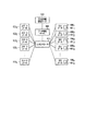
図4は、コンセントレータ200の構成を示す図である。
FIG. 4 is a diagram illustrating a configuration of the
コンセントレータ200は、筐体210を有する。筐体210は、樹脂によって構成されている。筐体210は、スマートメータ100とコンセントレータ200との配置方向に直交する方向、例えば水平方向に対向配置された第1の側壁211と第2の側壁212とを有する。第1の側壁211と第2の側壁212とは、第1の面200Aに接続する。
The
筐体210内に、電源回路基板221、通信部(第2通信部)222、無線通信部223、第1のアンテナ224、および第2のアンテナ225、制御部226等が設けられている。
In the
電源回路基板221は、通信部222、無線通信部223、および制御部226を駆動するための電力を生成するための回路領域221Aを有する。電源回路基板221は、筐体210内の、第1及び第2の側壁211,212のうちの第2の側壁212に近い側に設けられている。
The power
通信部222は、各電力受給所に設置されたスマートメータと通信を行う。通信部は、Power Line Communications(PLC)方式や無線マルチホップ方式(Wi-SUNやZigBee等)により、スマートメータと通信を行う。もし通信部222が無線通信によりスマートメータ100と通信を行うよう構成されている場合には、コンセントレータ200内に通信部200用のアンテナ(第3のアンテナ)222Bが更に設けられる。なお当該無線の通信範囲は、セルラー方式の無線通信よりも狭い。通信部222は、通信基板222Aに設けられている。アンテナ222Bは、通信基板222Aのグランド層222Dをアンテナの導体板として利用するモノポールタイプである。
The
無線通信部223は、データ収集サーバ300と無線通信を行う。無線通信部223は、セルラー方式で無線通信を行う。第1のアンテナ224および第2のアンテナ225は、無線通信部223に接続されている。第1のアンテナ224は、第1の側壁211近傍に固定されている。第1のアンテナ224の長手方向は、第1の側壁211に沿う方向となるよう設けられている。第2のアンテナ225は、第2の側壁212近傍に固定されている。第2のアンテナ225は、回路基板221の回路領域221Aよりも第2の側壁212側に設けられている。第2アンテナ225の長手方向は、第2の側壁212に沿う方向となるよう設けられている。
The
第1のアンテナ224は、無線通信部223および制御部226等を含む電子回路が配置されている制御基板227上の電子回路領域227Aより第1の側壁211側に設けられている。言い換えると、第1の側壁211と電子回路領域227Aとの間に、第1のアンテナ224が設けられている。制御基板227は、筐体210内の、第1及び第2の側壁211,212のうちの第1の側壁211に近い側に設けられている。制御基板227と通信基板222とは、第1の側壁211と第2の側壁212とに接続する第3の側壁213に直交する方向に配列されている。つまり、制御基板227と通信基板222とは、垂直方向に並んで配置されている。また、制御基板227と電源回路基板221とは、第2の側壁212に直交する方向に配列されている。つまり、制御基板227と電源回路基板221とは、水平方向に並んで配置されている。
The
そして、電源回路基板221の第2の側壁に平行した方向の長さは、制御基板227のそれよりも長い、かつ、通信部222のそれよりも長い。
The length in the direction parallel to the second side wall of the power
第1のアンテナ224と制御部226は、同一基板227上に実装されている。第1のアンテナ224と第2のアンテナ225によって、ダイバーシティアンテナが構成されている。第1のアンテナ224は、基板227のグランド層227Bをアンテナの導体板として利用するモノポールタイプである。第2のアンテナは、ダイポールタイプである。
The
なお、導体板は基板227に設けられていなくても良い。例えば、基板227以外の基板に設けられたグランド層、あるいは基板227以外の金属板金を導体板として用いても良い。また、第1のアンテナ224は、基板227上でなくスマートメータ200の筐体に設けられても良い。つまり、第1のアンテナ224は、例えば第1の側壁211の側壁面に設けられても良い。
Note that the conductor plate may not be provided on the
第2のアンテナ225は、第2の側壁212に設けられており、電源回路基板221より第2の側壁212側に位置している。言い換えると、第2の側壁212と電源回路基板221との間に、第2のアンテナ225が設けられている。電源回路基板221は、基板及び基板に設けられた各種電子部品・電子回路を有する。即ち、第2のアンテナは、電源回路基板221の電子回路領域より第2の側壁212側に設けられており、言い換えると、第2の側壁212と電源回路基板221の電子回路領域との間に、第2のアンテナ225が設けられている。第2のアンテナ225を第2の側壁212に設けても良い。なお図4において第2のアンテナ225は電源回路基板221の基板の外に設けられているが、第2のアンテナ225は電源回路基板221上に設けられても良い。
The
無線通信部223には、二本の給電線が接続される二つのアンテナポート2231、2232が設けられている。第1のアンテナ224が、給電線224FLを介してアンテナポート2231に接続されている。第2のアンテナ225が、給電線225FLを介してアンテナポート2232に接続されている。
The
第1のアンテナ224は、給電点224FPから、水平方向に直交する方向(設置されたときの垂直方向)、かつ設置されたときの下方向(以下、下方向)に延びている。即ち、第1のアンテナ224は、給電点224FPから、第1の側壁211と平行に通信部222と反対方向に延びている。なお第1のアンテナ224は、基板227上において給電点224FPから図4と反対方向に延びたものであっても良い。The
なお図4において、第1のアンテナ224の開放端2241は、下方向に向いているが、紙面上方向に向いていても良い。つまりアンテナ224は途中で曲がっていても良い。 第2のアンテナ225は、給電点225FPから、水平方向に直交する方向(設置されたときの垂直方向)、即ち第2の側壁212と平行に延びている。第2のアンテナ225の一方の開放端2251は、設置箇所に設置されたとき上方向に向いており、第2のアンテナ225の他方の開放端2252は、設置箇所に設置されたとき下方向に向いている。なお、第2のアンテナ225の開放端2251、2252が、同じ方向(上方向、あるいは下方向)を向くように、第2のアンテナ225の素子が曲がっていても良い。In FIG. 4, the
制御部226は、通信部222を用いて、各設置箇所のスマートメータ100から電力使用量を取得する。また、制御部226は、取得された電力使用量をデータ収集サーバ300に通知する。
The
第1のアンテナ224を第1の側壁211近傍に配置し、第2のアンテナ225を第2の側壁212近傍に配置することで、第1のアンテナ224および第2のアンテナ225がスマートメータ100内に設けられた金属部品による影響を受けづらくなる。その結果、第1のアンテナ224および第2のアンテナ225のアンテナ性能の劣化を抑制することが可能になる。
By arranging the
図5は、スマートメータ100およびコンセントレータ200を正面から見た図である。図5に示すように、スマートメータ100およびコンセントレータ200を正面から見ると、アンテナ224、225は、端子部101及び電力線から外れた位置に設けられている。
FIG. 5 is a front view of the
図6は、スマートメータ100およびコンセントレータ200を側面から見た図である。図6に示すように、スマートメータ100およびコンセントレータ200を側面から見ると、アンテナ224、225は、端子部101及び電力線から外れた位置に設けられている。
FIG. 6 is a side view of the
図5において、筐体210の水平方向の長さは、スマートメータ100の水平方向の長さより長いが、同じ長さであっても良い。図5のように筐体210の水平方向の長さがスマートメータ100の水平方向の長さよりも長い場合は、コンセントレータ200の筐体の蓋に設けられるねじ穴(ねじ穴101Aと重なるねじ穴)の位置は第1及び第2のアンテナよりも内側となる。言い換えると、ねじ穴101Aのうち第1の側壁211寄りに位置するねじ穴は、第1のアンテナ224を基準にして第2の側壁212側に設けられており、ねじ穴101Aのうち第2の側壁212寄りに位置するねじ穴は、第2のアンテナ225を基準にして第1の側壁211側に設けられている。筐体210の水平方向の長さがスマートメータ100の水平方向の長さと同程度の場合は、コンセントレータ200の筐体の蓋に設けられるねじ穴の位置は第1及び第2のアンテナの近傍となる。
In FIG. 5, the horizontal length of the
なお、第1のアンテナ224や第2のアンテナ225は、スマートメータ100とコンセントレータ200との配置方向に、スマートメータ100と重ならない位置に配置されていることが好ましいが、第1のアンテナ224や第2のアンテナ225がスマートメータ100と重なる位置に設けられた場合であっても、これらのアンテナが樹脂性の側壁近傍に設けられているため、良好な無線品質を保つことができる。
Note that the
モノポールタイプの第1のアンテナ224と、ダイポールタイプの第2のアンテナ225では、放射パターンが異なるものとなるため、アンテナ間の相関を落とすことが可能となり、ダイバーシティ効果を向上させることができる。
Since the monopole type
次に、図7のフローチャートを参照して、ガス使用量のデータ収集の処理の手順を説明する。なお、以下の方法においては、コンセントレータは、セルラー方式の無線通信を用いずに、電気使用量データをデータ収集サーバ300に通知しても良い。
Next, with reference to the flowchart of FIG. 7, the procedure of the data collection process of gas usage will be described. In the following method, the concentrator may notify the
先ず、各ガスメータ4001、4002、4003、...、400nがガス使用量を測定する(ステップB11)。各ガスメータ4001、4002、4003、...、400nは、測定により得られたガス使用量データを暗号化する(ステップB12)。各ガスメータ4001、4002、4003、...、400nは、暗号化されたガス使用量データを無線通信機を用いてコンセントレータ200に送信する(ステップB13)。コンセントレータ200は、。各ガスメータ4001、4002、4003、...、400nをデータ収集サーバ300に送信する(ステップB14)。データ収集サーバ300は、ガス使用量データを収集する(ステップB15)。データ収集サーバ300は、収集されたデータ(電気使用量データを含む)からガス使用量データを抽出する(ステップB16)。データ収集サーバ300は、抽出されたガス使用量データをガス使用量管理サーバ500に送信することによって、各設置箇所のガス使用量データをガス使用量管理サーバ500に提供する(ステップB17)。ガス使用量管理サーバ500は、提供されたガス使用量を受信することによって、ガス使用量データを取得する(ステップB18)。First, each gas meter 400 1 , 400 2 , 400 3 ,. . . 400 n measure the amount of gas used (step B11). Each gas meter 400 1 , 400 2 , 400 3 ,. . . , 400 n encrypts the gas usage data obtained by the measurement (step B12). Each gas meter 400 1 , 400 2 , 400 3 ,. . . , 400 n transmits the encrypted gas consumption data to the
図8は、コンセントレータ200の変形例を示す図である。図8に示すように、コンセントレータ200は、ダイポールタイプのアンテナを有していない。また、電源回路基板221は、垂直方向に対向する第3の側壁213と第4の側壁214のうちの第3の側壁213側に設けられている。第3の側壁213は、設置されたときに下になる。通信部222と制御基板227とは、第3の側壁213と第4の側壁214のうちの第4の側壁214側に設けられている。第4の側壁214は、設置されたときの上になる。通信部222と制御基板227は、水平方向に並んで配置されている。第1のアンテナ224は、第1の側壁211の近傍に設けられている。アンテナ222Bは、第2の側壁212の近傍に設けられている。
FIG. 8 is a diagram illustrating a modification of the
図9は、コンセントレータ200の変形例を示す図である。図9に示すように、電源回路基板221と通信部222と制御基板227との配置関係は、図8のコンセントレータと同様である。コンセントレータ200は、ダイポールタイプの第2のアンテナ225を有している。
FIG. 9 is a diagram illustrating a modification of the
図10は、コンセントレータ200の変形例を示す図である。図9に示すように、ダイポールタイムの第2のアンテナを有していない。電源回路基板221と通信部222と制御基板227との配置関係は、図4のコンセントレータと同様である。 第1のアンテナ224を第1の側壁211の近傍に設け、第2のアンテナ225を第2の側壁212の近傍に設けることで、第1のアンテナ224および第2のアンテナ225がスマートメータ100内に設けられた金属部品による影響を受けづらくなり、アンテナ性能の劣化を抑制することが可能になる。
FIG. 10 is a diagram illustrating a modification of the
本発明のいくつかの実施形態を説明したが、これらの実施形態は、例として提示したものであり、発明の範囲を限定することは意図していない。これら新規な実施形態は、その他の様々な形態で実施されることが可能であり、発明の要旨を逸脱しない範囲で、種々の省略、置き換え、変更を行うことができる。これら実施形態やその変形は、発明の範囲や要旨に含まれるとともに、特許請求の範囲に記載された発明とその均等の範囲に含まれる。 Although several embodiments of the present invention have been described, these embodiments are presented by way of example and are not intended to limit the scope of the invention. These novel embodiments can be implemented in various other forms, and various omissions, replacements, and changes can be made without departing from the scope of the invention. These embodiments and modifications thereof are included in the scope and gist of the invention, and are included in the invention described in the claims and the equivalents thereof.
Claims (11)
前記測定装置と前記コンセントレータとの配置方向に対して直交する方向に対向配置された第1の側壁と第2の側壁とを有する筐体であって、前記第1の側壁と前記第2の側壁は前記第1の面に接続した筐体と、
前記筐体内に設けられ、前記測定装置を含む複数の測定装置から複数の電力使用量を受信するための通信部と、
前記筐体内に設けられた、無線通信部と、
前記無線通信部を用いて、前記受信した前記複数の電力使用量をデータ収集サーバに通知する制御部と、
前記第1の側壁の近傍で、前記無線通信部と前記制御部とを含む電子回路が配置される制御基板上の前記第1の側壁側に沿って設けられ、前記無線通信部と接続される第1のアンテナと、
前記筐体内の電源回路基板と第2の側壁との間で、前記第2の側壁の近傍に沿って設けられ、前記無線通信部と接続される前記第1のアンテナと異なる形状の第2のアンテナと
を具備するコンセントレータ。 A concentrator in which a measuring device for measuring power usage is arranged on a first surface,
It said measuring device and said A housing having a first sidewall and a second sidewall opposed in the direction you orthogonal to the arrangement direction of the concentrator, the said first side wall second A side wall of the housing connected to the first surface;
A communication unit provided in the housing for receiving a plurality of power usage amounts from a plurality of measuring devices including the measuring device;
A wireless communication unit provided in the housing;
A controller that notifies the data collection server of the plurality of received power consumptions using the wireless communication unit;
Near the first side wall, provided along the first side wall on a control board on which an electronic circuit including the radio communication unit and the control unit is disposed, and connected to the radio communication unit A first antenna;
The second antenna having a shape different from that of the first antenna provided along the vicinity of the second side wall between the power circuit board in the housing and the second side wall and connected to the wireless communication unit . A concentrator comprising an antenna.
前記第2のアンテナは、ダイポールアンテナであり、
前記第1のアンテナと前記第2のアンテナとでダイバーシティアンテナを構成する請求項1に記載のコンセントレータ。 Said first antenna, Ri monopole antenna der,
The second antenna is a dipole antenna;
The concentrator according to claim 1 , wherein the first antenna and the second antenna constitute a diversity antenna .
前記制御基板と前記通信基板とは、前記第1の側壁と前記第2の側壁に接続する第3の側壁に直交する方向に並んで配列されている請求項1に記載のコンセントレータ。 The communication unit is provided on a communication board in the housing ,
The control board and the communication board, concentrator of claim 1 which are arranged side by side in a direction perpendicular to the third side wall of which connected to the first sidewall to the second sidewall.
前記測定装置と前記コンセントレータとの配置方向に対して直交する方向に対向配置された第1の側壁と第2の側壁とを有する筐体であって、前記第1の側壁と前記第2の側壁は前記第1の面に接続した筐体と、
前記筐体内の通信基板に設けられ、前記測定装置を含む複数の測定装置から複数の電力使用量を無線により受信するための通信部と、
前記筐体内の制御基板に設けられた無線通信部と、
前記筐体内の電源回路基板に設けられた電源回路と、
前記筐体内の前記制御基板に設けられ、前記無線通信部を用いて、前記受信した前記複数の電力使用量をデータ収集サーバに通知する制御部と、
前記第1の側壁の近傍で、前記制御基板上の前記第1の側壁側に沿って設けられ、前記無線通信部と接続される第1モノポールタイプアンテナと、
前記通信基板上の前記第2の側壁の近傍に沿って設けられた第2モノポールタイプアンテナと、
を具備し、
前記通信基板と前記制御基板は、前記第1の側壁と前記第2の側壁の間に並べて配置され、前記筐体が設置されたときの前記通信基板と前記制御基板の下側に前記電源回路基板が配置されているコンセントレータ。 A concentrator in which a measuring device for measuring power usage is arranged on a first surface,
It said measuring device and said A housing having a first sidewall and a second sidewall opposed in the direction you orthogonal to the arrangement direction of the concentrator, the said first side wall second A side wall of the housing connected to the first surface;
A communication unit that is provided on a communication board in the housing and wirelessly receives a plurality of power usage amounts from a plurality of measurement devices including the measurement device;
A radio communications unit provided in the housing of the control board,
A power supply circuit provided on a power supply circuit board in the housing;
A control unit provided on the control board in the housing, and notifying the data collection server of the plurality of received power consumptions using the wireless communication unit;
A first monopole antenna provided near the first side wall along the first side wall on the control board and connected to the wireless communication unit ;
A second monopole antenna provided along the vicinity of the second side wall on the communication board;
Equipped with,
The communication board and the control board are arranged side by side between the first side wall and the second side wall, and the power supply circuit is provided below the communication board and the control board when the housing is installed. Concentrator where the board is placed .
前記ガスメータが、ガス使用量を測定して、測定により得られたガス使用量データを暗号化して前記コンセントレータに送信し、
前記第2収集サーバが、前記第1収集サーバによって抽出された前記ガス使用量データを取得する、
データ取得方法。 A gas meter having the wireless communication device, a concentrator measuring device is arranged for measuring the power consumption on the first surface, in the direction you orthogonal to the arrangement direction of the concentrator and the measuring device a housing having a first sidewall and a second sidewall opposed, said first sidewall and said second sidewall is connected to the first surface, it is provided before Kikatami body the used communication unit for receiving a plurality of power usage from a plurality of measuring devices including a measuring device, and a radio communications unit provided in the housing, the wireless communication unit, the received the The first side wall on the control board on which an electronic circuit including the control unit for notifying the collection server of a plurality of power consumptions and the wireless communication unit and the control unit is disposed in the vicinity of the first side wall provided along the side, which is connected to the radio communication unit A first antenna, said the housing of the power supply circuit board between said second side wall, provided along the vicinity of the second side wall, said wireless said communication unit and Ru is connected to the first antenna A concentrator comprising second antennas of different shapes, a first collection server for collecting power usage data and gas usage data transmitted from the concentrator, and extracting the gas usage data, and the first collection A data acquisition method in a data acquisition system including a second collection server that receives data from a server,
The gas meter measures the gas usage, encrypts the gas usage data obtained by the measurement and sends it to the concentrator,
The second collection server acquires the gas usage data extracted by the first collection server;
Data acquisition method.
Applications Claiming Priority (1)
| Application Number | Priority Date | Filing Date | Title |
|---|---|---|---|
| PCT/JP2014/065118 WO2015186252A1 (en) | 2014-06-06 | 2014-06-06 | Concentrator |
Publications (2)
| Publication Number | Publication Date |
|---|---|
| JP6105164B2 true JP6105164B2 (en) | 2017-03-29 |
| JPWO2015186252A1 JPWO2015186252A1 (en) | 2017-04-20 |
Family
ID=54766345
Family Applications (1)
| Application Number | Title | Priority Date | Filing Date |
|---|---|---|---|
| JP2016525655A Active JP6105164B2 (en) | 2014-06-06 | 2014-06-06 | Concentrator |
Country Status (4)
| Country | Link |
|---|---|
| US (1) | US9888299B2 (en) |
| EP (2) | EP3154207B1 (en) |
| JP (1) | JP6105164B2 (en) |
| WO (1) | WO2015186252A1 (en) |
Families Citing this family (2)
| Publication number | Priority date | Publication date | Assignee | Title |
|---|---|---|---|---|
| US11009922B2 (en) * | 2015-02-27 | 2021-05-18 | Electro Industries/Gaugetech | Wireless intelligent electronic device |
| US9897461B2 (en) | 2015-02-27 | 2018-02-20 | Electro Industries/Gauge Tech | Intelligent electronic device with expandable functionality |
Family Cites Families (22)
| Publication number | Priority date | Publication date | Assignee | Title |
|---|---|---|---|---|
| JP3519507B2 (en) * | 1995-07-13 | 2004-04-19 | 松下電器産業株式会社 | Wireless device for automatic meter reading |
| JP3617218B2 (en) | 1996-11-11 | 2005-02-02 | 松下電器産業株式会社 | Antenna for equipment |
| US5986574A (en) * | 1997-10-16 | 1999-11-16 | Peco Energy Company | System and method for communication between remote locations |
| JP2002374112A (en) | 2001-06-13 | 2002-12-26 | Matsushita Electric Ind Co Ltd | Information communication device antenna |
| EP2203911A4 (en) * | 2007-10-25 | 2011-12-28 | Trilliant Networks Inc | Gas meter having ultra-sensitive magnetic material retrofitted onto meter dial and method for performing meter retrofit |
| JP2009253788A (en) | 2008-04-09 | 2009-10-29 | Ricoh Elemex Corp | Wireless communication unit and flowmeter equipped with the same |
| US8228209B2 (en) * | 2009-04-07 | 2012-07-24 | Rf Savvy Llc | Smart meter cover with integral untethered antenna elements for AMI communications |
| JP2011081518A (en) * | 2009-10-05 | 2011-04-21 | Panasonic Electric Works Co Ltd | Remote meter reading device |
| US9231730B2 (en) * | 2010-09-30 | 2016-01-05 | Panasonic Intellectual Property Management Co., Ltd. | Radio communication device |
| JP5711601B2 (en) * | 2011-04-28 | 2015-05-07 | 株式会社東芝 | Usage measurement system |
| JP2013021516A (en) * | 2011-07-11 | 2013-01-31 | Toshiba Corp | Consumed quantity measurement system, radio communication center device and program for the same measurement system |
| JP5701715B2 (en) * | 2011-08-12 | 2015-04-15 | 株式会社東芝 | Energy management device, power management system and program |
| JP2013106335A (en) * | 2011-11-17 | 2013-05-30 | Panasonic Corp | Radio equipment |
| EP2973928A4 (en) * | 2013-03-14 | 2016-11-02 | Powerwise Group Inc | Autonomous smart grid demand measurement system and method |
| FR3005228B1 (en) * | 2013-04-30 | 2016-11-25 | Electricite De France | COMMUNICATION INTERFACE BETWEEN EQUIPMENT AND A FLUID COUNTING SYSTEM |
| EP3072308B1 (en) * | 2013-11-22 | 2018-01-31 | Kamstrup A/S | Consumption meter with error-correction |
| WO2015136893A1 (en) * | 2014-03-11 | 2015-09-17 | 日本電気株式会社 | Metering device and communication control method |
| JP5976028B2 (en) * | 2014-03-27 | 2016-08-23 | 京セラドキュメントソリューションズ株式会社 | Electronics |
| US10243364B2 (en) * | 2014-05-19 | 2019-03-26 | Nec Corporation | Control device, control method, and program |
| US9612133B2 (en) * | 2014-07-14 | 2017-04-04 | International Technological University | Smart meter system communication methods |
| TWI579791B (en) * | 2015-11-30 | 2017-04-21 | 財團法人資訊工業策進會 | Advanced metering infrastructure system |
| CN205862557U (en) * | 2016-01-18 | 2017-01-04 | 国网山东省电力公司巨野县供电公司 | A kind of electric energy meter centralized automatic meter-reading device |
-
2014
- 2014-06-06 WO PCT/JP2014/065118 patent/WO2015186252A1/en active Application Filing
- 2014-06-06 JP JP2016525655A patent/JP6105164B2/en active Active
- 2014-06-06 EP EP14893755.0A patent/EP3154207B1/en active Active
- 2014-06-06 EP EP20190141.0A patent/EP3771113B1/en active Active
-
2016
- 2016-12-05 US US15/369,451 patent/US9888299B2/en active Active
Also Published As
| Publication number | Publication date |
|---|---|
| WO2015186252A1 (en) | 2015-12-10 |
| US20170085969A1 (en) | 2017-03-23 |
| EP3154207A1 (en) | 2017-04-12 |
| US9888299B2 (en) | 2018-02-06 |
| EP3154207B1 (en) | 2020-09-16 |
| EP3771113B1 (en) | 2022-07-27 |
| JPWO2015186252A1 (en) | 2017-04-20 |
| EP3771113A1 (en) | 2021-01-27 |
| EP3154207A4 (en) | 2018-01-31 |
Similar Documents
| Publication | Publication Date | Title |
|---|---|---|
| MX2014007272A (en) | Radio frequency identification tag. | |
| WO2015121758A3 (en) | Conductive loop antennas | |
| IN2014MN02070A (en) | ||
| JP6105164B2 (en) | Concentrator | |
| ATE417382T1 (en) | PLANAR ANTENNA | |
| JP6411026B2 (en) | Remote meter reading device | |
| RU2015104670A (en) | METHOD OF MEASUREMENT IN THE RANGE OF ULTRA-HIGH PARTIAL DISCHARGE FREQUENCIES AND THE RELATED DEVICE | |
| IN2014DN07909A (en) | ||
| MX360482B (en) | System and method for an antenna on a cable. | |
| EP3106842B1 (en) | Flow rate measurement device and wireless communication device | |
| CN104752825B (en) | The wireless communication device of antenna structure and the application antenna structure | |
| KR20100002855U (en) | Antenna mounting arrangement for cell phone with a metal casing | |
| EP2128931A4 (en) | Antenna arranging method and mounting device for communication device, and antenna device | |
| JP2009253788A (en) | Wireless communication unit and flowmeter equipped with the same | |
| MX2016009509A (en) | Remote monitoring system of the gas level content in stationary tanks. | |
| CN104200622B (en) | Mobile kilowatt meter reading-out system | |
| CN103682637B (en) | Radio communication device | |
| Herbert et al. | Assessment of a low‐profile planar antenna for a wireless sensor network monitoring the local water distribution network | |
| WO2019242953A1 (en) | Filter in a wireless charger for use in a vehicle, wireless charger and vehicle | |
| GB2529783A (en) | An electricity meter and an insulating carrier for a sensor component of an electricity meter | |
| CN112424997B (en) | Well lid and method for installing antenna assembly | |
| Kumar et al. | π-shape slotted microstrip patch antenna for ZigBee applications | |
| Jain et al. | Mobile tower radiation–Affects, Assessments and Monitoring of IIT Roorkee Campus | |
| EP2704251A1 (en) | Assembly comprising a device with a planar antenna | |
| Rezer et al. | Wireless sensor system for electrical cabinet monitoring |
Legal Events
| Date | Code | Title | Description |
|---|---|---|---|
| A131 | Notification of reasons for refusal |
Free format text: JAPANESE INTERMEDIATE CODE: A131 Effective date: 20161122 |
|
| A521 | Request for written amendment filed |
Free format text: JAPANESE INTERMEDIATE CODE: A523 Effective date: 20170119 |
|
| TRDD | Decision of grant or rejection written | ||
| A01 | Written decision to grant a patent or to grant a registration (utility model) |
Free format text: JAPANESE INTERMEDIATE CODE: A01 Effective date: 20170131 |
|
| A61 | First payment of annual fees (during grant procedure) |
Free format text: JAPANESE INTERMEDIATE CODE: A61 Effective date: 20170301 |
|
| R151 | Written notification of patent or utility model registration |
Ref document number: 6105164 Country of ref document: JP Free format text: JAPANESE INTERMEDIATE CODE: R151 |