JP6101047B2 - Information processing apparatus, control method therefor, and program - Google Patents
Information processing apparatus, control method therefor, and program Download PDFInfo
- Publication number
- JP6101047B2 JP6101047B2 JP2012245635A JP2012245635A JP6101047B2 JP 6101047 B2 JP6101047 B2 JP 6101047B2 JP 2012245635 A JP2012245635 A JP 2012245635A JP 2012245635 A JP2012245635 A JP 2012245635A JP 6101047 B2 JP6101047 B2 JP 6101047B2
- Authority
- JP
- Japan
- Prior art keywords
- temperature
- information
- processing apparatus
- memory chip
- temperature distribution
- Prior art date
- Legal status (The legal status is an assumption and is not a legal conclusion. Google has not performed a legal analysis and makes no representation as to the accuracy of the status listed.)
- Expired - Fee Related
Links
Images


Classifications
-
- G—PHYSICS
- G05—CONTROLLING; REGULATING
- G05D—SYSTEMS FOR CONTROLLING OR REGULATING NON-ELECTRIC VARIABLES
- G05D23/00—Control of temperature
- G05D23/19—Control of temperature characterised by the use of electric means
-
- G—PHYSICS
- G11—INFORMATION STORAGE
- G11C—STATIC STORES
- G11C11/00—Digital stores characterised by the use of particular electric or magnetic storage elements; Storage elements therefor
- G11C11/21—Digital stores characterised by the use of particular electric or magnetic storage elements; Storage elements therefor using electric elements
- G11C11/34—Digital stores characterised by the use of particular electric or magnetic storage elements; Storage elements therefor using electric elements using semiconductor devices
- G11C11/40—Digital stores characterised by the use of particular electric or magnetic storage elements; Storage elements therefor using electric elements using semiconductor devices using transistors
- G11C11/401—Digital stores characterised by the use of particular electric or magnetic storage elements; Storage elements therefor using electric elements using semiconductor devices using transistors forming cells needing refreshing or charge regeneration, i.e. dynamic cells
- G11C11/406—Management or control of the refreshing or charge-regeneration cycles
- G11C11/40611—External triggering or timing of internal or partially internal refresh operations, e.g. auto-refresh or CAS-before-RAS triggered refresh
-
- G—PHYSICS
- G05—CONTROLLING; REGULATING
- G05B—CONTROL OR REGULATING SYSTEMS IN GENERAL; FUNCTIONAL ELEMENTS OF SUCH SYSTEMS; MONITORING OR TESTING ARRANGEMENTS FOR SUCH SYSTEMS OR ELEMENTS
- G05B15/00—Systems controlled by a computer
- G05B15/02—Systems controlled by a computer electric
-
- G—PHYSICS
- G11—INFORMATION STORAGE
- G11C—STATIC STORES
- G11C11/00—Digital stores characterised by the use of particular electric or magnetic storage elements; Storage elements therefor
- G11C11/21—Digital stores characterised by the use of particular electric or magnetic storage elements; Storage elements therefor using electric elements
- G11C11/34—Digital stores characterised by the use of particular electric or magnetic storage elements; Storage elements therefor using electric elements using semiconductor devices
- G11C11/40—Digital stores characterised by the use of particular electric or magnetic storage elements; Storage elements therefor using electric elements using semiconductor devices using transistors
- G11C11/401—Digital stores characterised by the use of particular electric or magnetic storage elements; Storage elements therefor using electric elements using semiconductor devices using transistors forming cells needing refreshing or charge regeneration, i.e. dynamic cells
- G11C11/406—Management or control of the refreshing or charge-regeneration cycles
- G11C11/40626—Temperature related aspects of refresh operations
Landscapes
- Engineering & Computer Science (AREA)
- Microelectronics & Electronic Packaging (AREA)
- Computer Hardware Design (AREA)
- Physics & Mathematics (AREA)
- General Physics & Mathematics (AREA)
- Automation & Control Theory (AREA)
- General Engineering & Computer Science (AREA)
- Dram (AREA)
- Memory System (AREA)
Description
本発明は、CPUを含むSOCダイに積層されるWideIOメモリデバイスを具備する情報処理装置及びその制御方法、並びにプログラムに関するものである。 The present invention relates to an information processing apparatus including a WideIO memory device stacked on an SOC die including a CPU, a control method thereof, and a program.
マイクロプロセッサ等のCPUを備えた情報処理装置では、OSや各種アプリケーションを実行するためのデータの保存や、画像処理を実行するためのデータの一時保存のためにDRAMを用いることが多い。このDRAMは、CPUやSOC(System on a Chip)等に接続されて使用される。また近年、情報処理装置の多機能化・高機能化に伴って、必要となるDRAMのメモリ帯域が増加している。このため、DDR3やDDR4等の規格では、メモリのアクセス時のクロックの周波数を高くすることで、メモリ帯域を増加させている。またそれ以外に、CPUやASIC(Application Specific Integrated Circuit)に接続するDRAMチャネルを複数備えることでメモリ帯域を確保している。しかし、クロック周波数の高周波数化や複数のメモリチャネルの採用によって、消費電力が増加するという新たな問題が発生する。 In an information processing apparatus including a CPU such as a microprocessor, a DRAM is often used for storing data for executing an OS and various applications and temporarily storing data for executing image processing. This DRAM is used by being connected to a CPU, an SOC (System on a Chip) or the like. In recent years, the required memory bandwidth of DRAMs has increased with the increase in functionality and functionality of information processing apparatuses. For this reason, in standards such as DDR3 and DDR4, the memory bandwidth is increased by increasing the frequency of the clock when accessing the memory. In addition, a memory band is secured by providing a plurality of DRAM channels connected to a CPU and an ASIC (Application Specific Integrated Circuit). However, there is a new problem that power consumption increases due to an increase in clock frequency and the use of a plurality of memory channels.
そこで現在注目されているのが次世代DRAM規格であるWideIOである。WideIOは、TSV(Through Silicon Via)による3D積層技術を使い、SOCダイの上にDRAMチップを重ねて構成される。この特徴としては、512ビットの広いデータ幅で最大12.8GB/s(Gバイト/秒)以上の広帯域が得られるとともに、アクセス周波数を低く抑えているので低消費電力であることが挙げられる。また、TSVを採用したことで、従来のPoP(Package on Package)に比べてパッケージサイズを薄く小さくできる。更に、512ビットのデータ幅を、それぞれ128ビットのデータ幅の4つのチャネルに分割し、各チャネルを独立して制御できるように構成されている。例えば、チャネル1とチャネル2とをセルフリフレッシュ状態にし、チャネル3とチャネル4とを、通常のメモリアクセスに使用する等の使い方ができる。特許文献1には、このようなWideIOの基本的な構造や基本的なアクセス方法が記載されている。
In view of this, WideIO, which is the next generation DRAM standard, is currently attracting attention. WideIO uses a 3D stacking technique based on TSV (Through Silicon Via) and is configured by stacking DRAM chips on an SOC die. This feature includes a wide data width of 512 bits and a wide bandwidth of 12.8 GB / s (GB / sec) or more, and low power consumption because the access frequency is kept low. Further, by adopting TSV, the package size can be made thinner and smaller than conventional PoP (Package on Package). Further, the 512-bit data width is divided into four channels each having a 128-bit data width, and each channel can be controlled independently. For example,
WideIOの積層化構造では、SOCパッケージ内にチップを積層することで、構造的に熱の影響を受けやすくなるため、発熱に関連する問題が従来のDRAMよりも顕在化する。WideIOでは、その対策として、メモリの温度を検知する温度センサをチップに内蔵させることが規格化されており、温度センサによって検知された温度に応じてセルフリフレッシュ・レートを制御できる。 In the stacked structure of WideIO, the chip is stacked in the SOC package, so that it is structurally susceptible to heat, so that a problem related to heat generation becomes more obvious than in the conventional DRAM. In WideIO, as a countermeasure, it is standardized that a temperature sensor for detecting the temperature of the memory is built in the chip, and the self-refresh rate can be controlled according to the temperature detected by the temperature sensor.
また、WideIO規格に準拠して積層されたチップでは、チップ上で最も温度が高くなっている位置(以下、「ホットスポット」と称する。)の温度が、従来型のチップの場合よりも高くなる。これにより、ホットスポットの温度と非ホットスポットの温度との温度差が大きくなることが知られている。このため、例えば、チップ上で温度センサの位置と異なる位置にホットスポットが生じた場合、温度センサで検知される温度とホットスポットの温度との間に大きな差異が生じる可能性がある。その結果、温度センサによって検知された温度に応じてセルフリフレッシュ・レートを設定した場合、ホットスポットに起因して、DRAMに記憶された内容の消失や消費電力の増大を招く可能性がある。 In addition, in a chip stacked in conformity with the WideIO standard, the temperature at a position where the temperature is highest on the chip (hereinafter referred to as “hot spot”) is higher than that in the case of a conventional chip. . This is known to increase the temperature difference between the hot spot temperature and the non-hot spot temperature. For this reason, for example, when a hot spot is generated at a position different from the position of the temperature sensor on the chip, there is a possibility that a large difference occurs between the temperature detected by the temperature sensor and the temperature of the hot spot. As a result, when the self-refresh rate is set according to the temperature detected by the temperature sensor, the content stored in the DRAM may be lost or the power consumption may be increased due to the hot spot.
このような現象に対処するために、ホットスポットと、温度センサが設けられた位置との間の温度差を示す「サーマルオフセット」と称される値が、規格として定められている。サーマルオフセット値は、ホットスポットと、温度センサが設けられた位置との温度差に合わせて段階的に設定される。この規格では、設定されたサーマルオフセット値に基づいてセルフリフレッシュ・レートを設定することで、このような温度差を考慮したセルフリフレッシュ・レートの制御を実現する。 In order to cope with such a phenomenon, a value called “thermal offset” indicating a temperature difference between the hot spot and the position where the temperature sensor is provided is defined as a standard. The thermal offset value is set stepwise in accordance with the temperature difference between the hot spot and the position where the temperature sensor is provided. In this standard, the self-refresh rate is controlled in consideration of such a temperature difference by setting the self-refresh rate based on the set thermal offset value.
しかし、ホットスポットの温度と温度センサによって検知される温度との間との温度差を適切に推定し、サーマルオフセットを適切に設定することは容易ではない。これは、チップ上のホットスポットの位置及び温度が、WideIOメモリデバイスに対するメモリアクセスの状態やSOCダイの処理状態等に応じた、WideIOメモリデバイスの動作状態に依存して、時々刻々と変化するためである。このため、WideIOメモリデバイスの動作状態を考慮して、適切にサーマルオフセットを設定することが必要である。 However, it is not easy to appropriately estimate the temperature difference between the temperature of the hot spot and the temperature detected by the temperature sensor and set the thermal offset appropriately. This is because the position and temperature of the hot spot on the chip change from moment to moment depending on the operating state of the WideIO memory device according to the memory access state to the WideIO memory device, the processing state of the SOC die, and the like. It is. For this reason, it is necessary to appropriately set the thermal offset in consideration of the operation state of the WideIO memory device.
本発明は、上述の課題に鑑みてなされたものである。本発明は、情報処理装置でWideIOメモリデバイスを使用する場合に、SOCダイ及びWideIOメモリデバイスの動作状況を考慮して、適切にサーマルオフセット値を設定する技術を提供することを目的としている。 The present invention has been made in view of the above-described problems. An object of the present invention is to provide a technique for appropriately setting a thermal offset value in consideration of the operating conditions of an SOC die and a WideIO memory device when a WideIO memory device is used in an information processing apparatus.
上記目的を達成するために、本発明の一態様に係る情報処理装置は以下のような構成を備える。即ち、
CPUを含むSOCダイに積層されるWideIOメモリデバイスを具備する情報処理装置であって、
前記WideIOメモリデバイスに含まれるメモリチップに設けられた温度センサから、前記温度センサの位置における前記メモリチップの温度を示すセンサ情報を取得する取得手段と、
予め実行される解析によって生成された、前記メモリチップ内の温度分布に関する情報を含む既定温度情報であって、前記SOCダイ及び前記WideIOメモリデバイスの動作状況に対応する前記既定温度情報と、前記取得手段によって取得されたセンサ情報とに基づいて、前記メモリチップ内の現在の温度分布を示す温度分布情報を生成する生成手段と、
前記温度分布情報が示す温度分布に含まれる、前記温度センサの位置における温度と、前記メモリチップ内で最も温度が高くなっている位置における温度との差分に応じて、前記メモリチップのリフレッシュ動作に用いるサーマルオフセット値を設定する設定手段と
を備えることを特徴とする。
In order to achieve the above object, an information processing apparatus according to an aspect of the present invention includes the following arrangement. That is,
An information processing apparatus comprising a WideIO memory device stacked on an SOC die including a CPU,
Obtaining means for obtaining sensor information indicating a temperature of the memory chip at a position of the temperature sensor from a temperature sensor provided in a memory chip included in the WideIO memory device;
Pre-determined temperature information generated by a pre-executed analysis and including information related to a temperature distribution in the memory chip, the predetermined temperature information corresponding to operating states of the SOC die and the WideIO memory device, and the acquisition Generating means for generating temperature distribution information indicating the current temperature distribution in the memory chip based on the sensor information acquired by the means;
The refresh operation of the memory chip is performed according to the difference between the temperature at the position of the temperature sensor included in the temperature distribution indicated by the temperature distribution information and the temperature at the highest temperature position in the memory chip. Setting means for setting a thermal offset value to be used.
本発明によれば、情報処理装置でWideIOメモリデバイスを使用する場合に、SOCダイ及びWideIOメモリデバイスの動作状況を考慮して、適切にサーマルオフセット値を設定する技術を提供できる。 ADVANTAGE OF THE INVENTION According to this invention, when using a WideIO memory device with an information processing apparatus, the technique which sets a thermal offset value appropriately can be provided in consideration of the operating condition of an SOC die and a WideIO memory device.
以下、本発明を実施するための形態について図面を用いて説明する。尚、以下の実施形態は特許請求の範囲に係る発明を限定するものでなく、また実施形態で説明されている特徴の組み合わせの全てが発明の解決手段に必須のものとは限らない。以下の実施形態では、本発明を適用した情報処理装置の一例として、スキャン、プリンタ、コピーなどの複数の機能を有するMFP(デジタル複合機)を例に説明する。 Hereinafter, embodiments for carrying out the present invention will be described with reference to the drawings. The following embodiments do not limit the invention according to the claims, and all combinations of features described in the embodiments are not necessarily essential to the solution means of the invention. In the following embodiments, an MFP (digital multifunction peripheral) having a plurality of functions such as scan, printer, and copy will be described as an example of an information processing apparatus to which the present invention is applied.
<MFP100の構成>
図1は、本実施形態に係るMFP(デジタル複合機)の全体構成を示すブロック図である。
<Configuration of
FIG. 1 is a block diagram showing an overall configuration of an MFP (digital multifunction peripheral) according to the present embodiment.
MFP100は、画像入力デバイスであるスキャナ116と画像出力デバイスであるプリンタエンジン117とを有し、これらはデバイスインターフェース(I/F)107を介してシステムバス118に接続されている。MFP100は、CPU101の制御の下に、スキャナ116による原稿の画像の読み取りや、プリンタエンジン117による印刷を行うことができる。またMFP100は、LAN114や公衆回線(PSTN)115と接続しており、これらを介してLANや公衆回線に接続された外部機器のデバイス情報や画像データの入出力を行うことができる。
The MFP 100 includes a
CPU101は、ROM106に記憶されたブートプログラムによりHDD105からWideIO−SDRAM113に展開されたプログラムを実行することにより、このMFP100の動作を制御している。
The
操作部102は、キーボードやタッチパネル等の入力部や表示部を有し、ユーザからの指示を受付け、また表示部によりユーザへのメッセージや処理の結果などを表示する。ネットワークI/F103は、例えばLANカード等で実現され、LAN114を介して外部機器との間でデバイス情報や画像データの入出力を行う。モデム104は、公衆回線115を介して外部機器との間で制御情報や画像データの入出力を行う。HDD(ハードディスクドライブ)105は、OSや各種アプリケーションプログラム等を記憶し、また入力された画像データ等を格納する。ROM106は、ブートプログラムや各種データを記憶している。デバイスI/F107は、スキャナ116やプリンタエンジン117と接続し、これらスキャナ116やプリンタエンジン117とシステムバス118との間で画像データの転送処理を行う。
The
MFP100は、図1に示すように、それぞれ個別の画像処理機能を実行する複数の画像処理部108〜111(編集用画像処理部108、プリント画像処理部109、スキャン画像処理部110、及びRIP(ラスタイメージプロセッサ)111)を備えている。編集用画像処理部108は、画像データの回転や変倍、色処理、トリミング・マスキング、2値変換、多値変換、白紙判定等の各種画像処理を行う。プリント画像処理部109は、プリンタエンジン117に出力する画像データに対して、そのプリンタエンジン117に応じた画像処理等を行う。スキャン画像処理部110は、スキャナ116から入力される画像データに対して、補正、加工、編集等の各種処理を行う。RIP111は、ページ記述言語(PDL)コードをイメージデータに展開する。尚、本実施形態では、画像処理部108〜111は、それぞれが個別の機能を実行する複数の機能モジュールの一例である。
As shown in FIG. 1, the
WideIOコントローラ112は、例えばCPU101、画像処理部108〜111等からのメモリアクセスコマンドを、WideIO−SDRAM113が解釈可能なコマンドに変換して、WideIO−SDRAM113に対してアクセスを行う。WideIO−SDRAM113は、CPU101により実行されるプログラムを格納し、またCPU101が動作するためのシステムワークメモリを提供している。また、WideIO−SDRAM113は、入力された画像データを一時記憶するための画像メモリでもある。システムバス118は、図1に示すように、上述した各デバイスとCPU101とを接続し、制御信号やデータ等を転送している。
The
<WideIO−SDRAM113の構造>
図2は、本実施形態に係るWideIO−SDRAM113の構造を示す模式図で、図2(A)はWideIO−SDRAMとSOCダイを側面から見た側面図であり、図2(B)は上側から見た上面図である。
<Structure of WideIO-
FIG. 2 is a schematic view showing the structure of the WideIO-
SOCダイ201は、本実施形態では、例えば、CPU101、デバイスI/F107、画像処理部108〜111等を備えている。WideIO−SDRAMチップ(メモリチップ)202〜205は、SOCダイ201の上に積層され、シリコン貫通ビア(TSV)206によりSOCダイ201と接続されている。WideIO−SDRAMチップは、必要とするメモリ容量に応じて最大4層まで積層することができ、図2(A)は4層を積層した例を示す。SOCパッケージ207は、SOCダイ201とWideIO−SDRAMチップ202〜205とを1つのパッケージに収容したものである。WideIO−SDRAM I/F208は、図2(B)に示されるように、SOCダイ201及びWideIO−SDRAMチップ202〜205の中央部に配置される。
In the present embodiment, the SOC die 201 includes, for example, a
<WideIOコントローラ112の構成>
図3は、本実施形態に係るWideIOコントローラ112の内部構成を示すブロック図である。
<Configuration of
FIG. 3 is a block diagram showing an internal configuration of the
図3において、WideIOコントローラ112は、図1に示したようにシステムバス118とWideIO−SDRAM113との間に接続されている。WideIOコントローラ112は、図1では図示していない温度センサ309〜312と接続されている。
In FIG. 3, the
SDRAM301〜304は、WideIO−SDRAM113に設けられた4つのメモリであり、図3に示すように、各々が専用のインターフェース(I/F)を備える。これらの専用I/Fは、上述したようにSOCダイ201に積層されるWideIO−SDRAMチップ202〜205の4つのチャネル(メモリチャネル)に相当する。また、これらの専用I/Fは、図2(B)のWideIO−SDRAM I/F208に相当している。メモリコントローラ305〜308は、SDRAM301〜304に対して、個別に電源電圧及びクロック信号の供給及び停止等の制御を実行可能である。メモリコントローラ305〜308のそれぞれは、システムバス118からのメモリアクセスコマンドを、接続されている対応するSDRAMに対して、そのSDRAMが解釈可能なコマンドに変換してアクセスする。尚、本実施形態において、WideIO−SDRAM113(SDRAM301〜304)は、CPUを含むSOCダイに積層されるWideIOメモリデバイスの一例である。
The
温度センサ309〜312は、SDRAM301〜304のうち、対応するSDRAMの温度を計測している。温度取得I/F315は、SDRAM301〜304の温度を示す温度情報を、温度センサ309〜312から取得する。
The
レジスタI/F313は、不図示のレジスタ専用バスを経由して、CPU101からのアクセスを受け付ける。レジスタ314は、温度取得I/F315が温度センサ309〜312から取得した各温度情報(センサ情報)や、CPU101から設定されるメモリコントローラ305〜308の各動作モードの設定情報を記憶する。温度取得I/F315は、後述する温度情報格納レジスタ402(図4)からの温度情報の取得要求を検知すると、後述する温度センサ指定レジスタ401(図4)で指定された温度センサに対して、温度情報を取得するためのコマンドを発行する。これにより、温度取得I/F315は、当該温度センサから温度情報を取得する。温度取得I/F315は、取得した温度情報を、後述する温度情報格納レジスタ402へ出力(格納)する。
The register I /
<WideIOコントローラ112内のレジスタ314の構成>
図4は、本実施形態に係るレジスタ314の構成を説明する図である。
<Configuration of
FIG. 4 is a diagram illustrating the configuration of the
レジスタ314は、温度センサ指定レジスタ401、温度情報格納レジスタ402、及びメモリコントローラ動作モード設定レジスタ403〜406を有している。レジスタ314は、更に、サーマルオフセットステータスレジスタ407〜410、及びサーマルオフセットレジスタ411〜414を有している。
The
温度センサ指定レジスタ401は、CPU101が温度センサの温度情報(センサ情報)を取得したい場合に、その対象となる温度センサを指定するための情報を格納するレジスタである。本実施形態においては、4個の温度センサを備える例を用いて説明しているため、2ビットのレジスタで構成され、2ビットの各状態によって4個の温度センサのそれぞれを特定することができる。
The temperature
温度情報格納レジスタ402は、CPU101からの温度情報の取得要求が入力されると、温度センサ指定レジスタ401で指定された温度センサの温度情報を取得するように温度取得I/F315に対して要求する。また、温度情報格納レジスタ402は、温度取得I/F315から取得した温度情報を格納し、CPU101からの温度情報の読み出し要求に応じて、そこに格納している温度情報を出力する。
When the temperature information acquisition request from the
メモリコントローラ動作モード設定レジスタ403〜406は、メモリコントローラ305〜308の動作モードをそれぞれ設定するためのレジスタである。メモリコントローラ動作モード設定レジスタ403〜406のそれぞれには、SDRAM301〜304のそれぞれのメモリ制御に関する設定値が格納される。ここでメモリ制御に関する設定値としては、例えば、SDRAM301〜304のリフレッシュ動作の時間間隔(リフレッシュ周期)、メモリアクセスに関するタイミングパラメータ等がある。
The memory controller operation mode setting registers 403 to 406 are registers for setting the operation modes of the
サーマルオフセットステータスレジスタ407〜410は、メモリコントローラ305〜308がそれぞれSDRAM301〜304に対して設定したサーマルオフセット値を保持しておくためのレジスタである。なお、サーマルオフセット値は、後述するように、SDRAM301〜304のそれぞれのリフレッシュ動作に用いられる。メモリコントローラ305〜308は、SDRAM301〜304に対してサーマルオフセット値を設定した後、SDRAM301〜304に、確認のためのリードアクセスをすることで、設定したサーマルオフセット値をそれぞれ読み出す。メモリコントローラ305〜308は、読み出したサーマルオフセット値をサーマルオフセットステータスレジスタ407〜410にそれぞれ記憶させる。尚、CPU101からサーマルオフセットステータスレジスタ407〜410へのライトアクセスは無効である。
The thermal offset status registers 407 to 410 are registers for holding thermal offset values set by the
サーマルオフセットレジスタ411〜414は、メモリコントローラ305〜309がそれぞれSDRAM301〜304に対して新たに設定すべきサーマルオフセット値を保持しておくためのレジスタである。CPU101は、後述するように、SDRAM301〜304に対して新たに設定すべきサーマルオフセット値を決定するとともに、決定した値をサーマルオフセットレジスタ411〜414に設定する。
The thermal offset
<SOCパッケージ207と温度センサ309〜312の配置>
図5は、図2のWideIO−SDRAMチップ202〜205とSOCダイ201の物理的な位置関係を、よりわかり易く説明するSOCパッケージ207の俯瞰図である。
<Arrangement of
FIG. 5 is an overhead view of the
SOCダイ201は、CPU101、デバイスI/F107、前述の画像処理部108〜111等を備えている。SOCパッケージ207の平面を4分割した時の左上、右上、右下、左下が、それぞれ図2(B)のメモリチャネル1〜4に相当する。また同様に、4分割した領域は、図3のSDRAM301〜304にも相当している。前述したように、WideIO−SDRAM113は、SOCダイ201の上に積層されるメモリである。また、本実施形態においては、SDRAM301〜304の各デバイスは、図5のようにSOCダイ201を4分割した領域の各上部にそれぞれ4層で積層されているものとする。SDRAM301〜304の各デバイスには、それぞれのメモリの内部温度が計測できるように、温度センサ309〜312が内蔵されている。ただし、各SDRAMの配置や温度センサの配置は図5に限定されるものではなく、一例に過ぎない。また、温度センサ309〜312は、SOCダイ201の内部に設けられていてもよいし、あるいは、WideIO−SDRAM113のメモリ内部に設けられていてもよい。
The SOC die 201 includes a
このように、本実施形態では、WideIO−SDRAMチップ(メモリチップ)202〜205は、図2(B)に示すように、複数のメモリチャネル1〜4にそれぞれ対応する複数のチップ領域(SDRAM301〜304)に分割して使用される。また、複数のチップ領域には、個別に温度センサ309〜312が設けられている。
Thus, in this embodiment, as shown in FIG. 2B, the WideIO-SDRAM chips (memory chips) 202 to 205 have a plurality of chip regions (
<既定温度情報の内容>
本実施形態では、CPU101は、SDRAM301〜304のそれぞれについて、メモリチップ内の現在の温度分布を示す温度分布情報を生成し、生成した温度分布情報に基づいて、それぞれのリフレッシュ動作に用いるサーマルオフセット値を設定する。具体的には、CPU101は、温度センサ309〜312からそれぞれ取得される温度情報(センサ情報)と、予め実行された解析によって生成された「既定温度情報」とに基づいて、サーマルオフセット値の設定に用いる「温度分布情報」を生成する。この既定温度情報は、SDRAM301〜304のそれぞれについて予め生成された、メモリチップ内の温度分布を含む情報であり、SOCダイ201及びWideIO−SDRAM113の個別の動作状況に対応している。なお、後述する「更新温度情報」は、センサ情報と既定温度情報とに基づいて生成される温度分布情報の一例である。
<Contents of preset temperature information>
In the present embodiment, the
ここでは、上述の既定温度情報の具体例について説明する。本実施形態では、SDRAM301〜304のそれぞれについて、平面状のメモリチップ内の領域を複数の領域に分割して得られる各領域の温度の分布を、メモリチップ内の温度分布として評価する。図6は、SDRAM301の(平面状の)領域全体600を、X軸方向に8分割、Y軸方向に8分割して、合計64個の領域に分割した例を示している。本実施形態では、SDRAM301〜304のそれぞれの領域全体600を、図6に示すように64分割する場合を想定し、各領域を座標(X,Y)((0,0)〜(7,7))で特定するものとする。なお、以下では、SDRAM301〜304のうち、主としてSDRAM301について説明するが、SDRAM302〜304についても同様である。
Here, a specific example of the above-described predetermined temperature information will be described. In the present embodiment, for each of the
図7(A)及び(B)は、本実施形態で用いる既定温度情報の内容の一例を示す図である。本実施形態で用いる既定温度情報は、SDRAM301上の所定位置(図6に示す、分割された各領域に相当。)の温度を示す温度情報をテーブル化したものである。既定温度情報は、SOCダイ201の設計時及び製造時に予め実行される、熱シミュレーション等の数値解析によって生成され、MFP100の出荷前にHDD105またはROM106に予め格納される。なお、図7では、環境温度が25℃である場合の既定温度情報を示しているが、異なる環境温度に対応した既定温度情報を予め生成し、利用可能としてもよい。
FIGS. 7A and 7B are diagrams illustrating an example of the contents of the predetermined temperature information used in the present embodiment. The predetermined temperature information used in the present embodiment is a table of temperature information indicating the temperature at a predetermined position on the SDRAM 301 (corresponding to each divided area shown in FIG. 6). The predetermined temperature information is generated by numerical analysis such as thermal simulation that is executed in advance when the SOC die 201 is designed and manufactured, and is stored in the
既定温度情報は、予め実行される数値解析によって、SOCダイ201及びWideIO−SDRAM113の個別の動作状況に対応して予め個別に生成されればよい。これは、MFP100が実行する動作に依存して、SOCダイ201の動作状況、及びSOCダイ201の動作に応じたWideIO−SDRAM113へのメモリアクセスの状況が変化する結果、SDRAM301の温度分布が変化するためである。MFP100が実行する異なる複数の処理に対応して個別に既定温度情報を用意することによって、SOCダイ201及びWideIO−SDRAM113の動作状況に応じた、SDRAM301の温度分布の変化を、精度良く推定することが可能になる。
The predetermined temperature information may be generated individually in advance corresponding to individual operation states of the SOC die 201 and the WideIO-
上述の数値解析では、MFP100がプリント処理、スキャン処理等の個別の処理を実行する際の、SOCダイ201(CPU101)の動作状況と、SOCダイ201の動作に応じたWideIO−SDRAM113へのメモリアクセスの状況とを解析すればよい。更に、SOCダイ201の動作状況及びWideIO−SDRAM113へのメモリアクセスの状況に応じた、メモリチップ(SDRAM301〜304)内の温度分布の時間変化を解析すればよい。なお、メモリチップ内の温度分布は、例えば、メモリチップの表面の温度の分布を示す情報である。
In the numerical analysis described above, the operation state of the SOC die 201 (CPU 101) when the
図7(A)は、MFP100がプリント処理を実行する場合の、SDRAM301の既定温度情報の例を示している。一方、図7(B)は、MFP100がスキャン処理を実行する場合の、SDRAM301の既定温度情報の例を示している。本実施形態では、プリント処理及びスキャン処理に対応する既定温度情報のみを図7に示している。しかし、MFP100が実行する他の処理に対応して、更に別の既定温度情報を予め生成し、利用可能としてもよい。例えば、画像編集、FAX送信/受信、電子メール送信、各種のアプリケーション処理等の処理をMFP100が実行する際の、SOCダイ201及びWideIO−SDRAM113の動作状況に対応する既定温度情報を、予め生成してもよい。あるいは、MFP100の特定の動作状態(例えば、待機状態(アイドリング状態)またはスリープ状態)におけるCPU101の動作率に応じたSOCダイ201及びWideIO−SDRAM113の動作状況に対応する既定温度情報を予め生成してもよい。
FIG. 7A shows an example of the default temperature information of the
図7に示すX座標及びY座標は、図6に示すX座標及びY座標にそれぞれ対応している。また、温度C0〜C4は、MFP100でプリント処理またはスキャン処理が一定時間継続した際の、各領域(X,Y)((0,0)〜(7,7))における時間別の温度をそれぞれ示している。即ち、温度C0〜C4は、SDRAM301の各領域における温度の時間変化を示している。
The X coordinate and Y coordinate shown in FIG. 7 correspond to the X coordinate and Y coordinate shown in FIG. 6, respectively. The temperatures C0 to C4 are the time-dependent temperatures in the respective regions (X, Y) ((0, 0) to (7, 7)) when the printing process or the scanning process is continued for a certain time in the
ここで、図8は、MFP100でプリント処理が実行される場合の、SDRAM301の温度分布についての熱シミュレーションの結果の一例を示す図である。図8に示すグラフ801は、SDRAM301の特定の領域(7,7)についての温度の変化(温度特性)を表している。なお、X軸は時間、Y軸は温度を示し、温度C0〜C4は、図7(A)に示す領域(7,7)の温度C0〜C4に対応している。
Here, FIG. 8 is a diagram illustrating an example of a result of a thermal simulation of the temperature distribution of the
図8において、温度C0は、SOCダイ201が非動作状態であり、メモリチップ(SDRAM301)内の温度が位置によらず一様である場合の温度を示している。温度C1は、メモリチップ内の領域(7,7)が温度C0の状態で、SOCダイ201がプリント処理のための動作を開始し、当該動作を時間t_C01だけ継続した時点における、領域(7,7)の温度を示している。同様に、温度C2、C3及びC4は、温度C1、C2及びC3を起点として、プリント処理のための動作を時間t_C12、t_C23及びt_C34だけ継続した時点における、領域(7,7)の温度をそれぞれ示している。図8に示すように、本実施形態で用いる既定温度情報は、メモリチップ内を複数の領域に分割して得られる各領域の温度を、異なる複数の時点においてサンプリングした情報を含んでいる。即ち、既定温度情報は、SOCダイ201が特定の動作を開始した後の、異なる複数の時点における各領域の温度を示す情報を、テーブル化した情報として含んでいる。 In FIG. 8, a temperature C0 indicates a temperature when the SOC die 201 is in a non-operating state and the temperature in the memory chip (SDRAM 301) is uniform regardless of the position. The temperature C1 is the region (7, 7) when the SOC die 201 starts an operation for print processing in a state where the region (7, 7) in the memory chip is the temperature C0 and the operation is continued for the time t_C01. The temperature of 7) is shown. Similarly, the temperatures C2, C3, and C4 are the temperatures of the regions (7, 7) when the operations for the printing process are continued for the times t_C12, t_C23, and t_C34, respectively, starting from the temperatures C1, C2, and C3. Show. As shown in FIG. 8, the predetermined temperature information used in the present embodiment includes information obtained by sampling the temperature of each region obtained by dividing the memory chip into a plurality of regions at a plurality of different time points. That is, the predetermined temperature information includes information indicating the temperature of each region at a plurality of different time points after the SOC die 201 starts a specific operation as tabulated information.
なお、図8では、時間t_C01、t_C12、T_C23及びt_C34はそれぞれ異なる長さに設定されている。即ち、図7に示す既定温度情報に含まれる各領域の温度には、非一様な時間間隔でサンプリングされた温度が用いられている。しかし、サンプリングの時間間隔は、非一様な時間間隔であっても等間隔であってもよい。また、既定温度情報に含まれる各領域の温度のサンプル数は、図8に示すように5個であってもよいし、5個より少ない、または5個よりも多いサンプル数であってもよい。このように、本実施形態を変形した場合にも、後述する本実施形態の処理と同等の処理を実現し、かつ、同様の効果を得ることが可能である。 In FIG. 8, the times t_C01, t_C12, T_C23, and t_C34 are set to different lengths. That is, the temperature sampled at non-uniform time intervals is used as the temperature of each region included in the predetermined temperature information shown in FIG. However, the sampling time interval may be a non-uniform time interval or an equal interval. Further, the number of samples of the temperature of each region included in the predetermined temperature information may be five as shown in FIG. 8, or may be less than five or more than five. . Thus, even when the present embodiment is modified, it is possible to realize a process equivalent to the process of the present embodiment to be described later and obtain the same effect.
<更新温度情報(温度分布情報)の内容>
次に、上述のように、温度センサ309〜312からそれぞれ取得される温度情報(センサ情報)と、予め実行された解析によって生成された既定温度情報とに基づいて生成される、温度分布情報(更新温度情報)の具体例について説明する。
<Contents of updated temperature information (temperature distribution information)>
Next, as described above, the temperature distribution information (sensor information) acquired from each of the
図9は、本実施形態で用いる更新温度情報の内容の一例を示す図である。本実施形態では、CPU101は、SOCダイ201及びWideIO−SDRAM113の動作状況に応じて、SDRAM301〜304のそれぞれの現在の温度分布を推定し、テーブル化した情報として、推定した温度分布を保持する。更新温度情報は、既定温度情報に基づいてリアルタイムに(例えば、予め設定された更新間隔で)更新されうる。
FIG. 9 is a diagram illustrating an example of the content of the updated temperature information used in the present embodiment. In the present embodiment, the
本実施形態で用いる更新温度情報は、SDRAM301上の所定位置(図6に示す、分割された各領域に相当。)における、更新済みの温度(更新温度)を示す温度情報を、図9に示すようにテーブル化したものである。なお、図9に示すX座標及びY座標は、図7と同様、図6に示すX座標及びY座標にそれぞれ対応している。 The update temperature information used in this embodiment is temperature information indicating the updated temperature (update temperature) at a predetermined position on the SDRAM 301 (corresponding to each divided area shown in FIG. 6). It is a table. Note that the X and Y coordinates shown in FIG. 9 correspond to the X and Y coordinates shown in FIG. 6, respectively, as in FIG.
図9に示す更新温度情報は、図7に示す既定温度情報に基づいて生成できる。更新温度情報は、例えば、温度センサ309からの温度情報が示す、温度センサ309の位置におけるSDRAM301の温度を基準として、SOCダイ201及びWideIO−SDRAM113の動作状況に対応する既定温度情報に基づいて生成される。なお、このような更新温度情報の生成処理の具体例については、図10を用いて後述する。
The updated temperature information shown in FIG. 9 can be generated based on the predetermined temperature information shown in FIG. The updated temperature information is generated based on predetermined temperature information corresponding to the operating conditions of the SOC die 201 and the WideIO-
図9において、温度情報901は、メモリチップ(SDRAM301)内で、温度センサ309が設けられた位置(領域)における温度を示している。本実施形態では、一例として、温度センサ309が設けられた位置を、(X,Y)=(4,5)としている。ただし、温度センサ309の位置がその位置のみに限定されることはなく、メモリチップ内の任意の位置に温度センサ309を設けることが可能である。また、温度情報902は、更新温度情報が示す現在のメモリチップ内の温度分布に含まれる、メモリチップ内で最も温度が高くなっている位置(ホットスポット)における温度を示している。即ち、図9に示す更新温度情報は、メモリチップ内の領域(7,7)にホットスポットが存在することを示している。本実施形態は、後述するように、CPU101は、更新温度情報が示す温度分布に含まれる、温度センサの位置における温度(温度情報901)と、ホットスポットにおける温度(温度情報902)との差分に応じて、サーマルオフセット値を設定する。
In FIG. 9,
<更新温度情報(温度分布情報)の生成及び更新>
次に、図10のフローチャートを参照して、本実施形態における更新温度情報の生成及び更新処理の手順について説明する。尚、この処理を実行するためのプログラムは、HDD105に予めインストールされている。この処理は、CPU101がHDD105からSDRAM301にプログラムを展開し、展開したプログラムを実行することによって、MFP100上で実現される。以下ではSDRAM301についての処理を説明するが、CPU101は、SDRAM302〜304についても同様の処理を実行する。
<Generation and update of updated temperature information (temperature distribution information)>
Next, with reference to the flowchart of FIG. 10, the procedure of the update temperature information generation and update process in this embodiment will be described. Note that a program for executing this process is installed in the
まず、S1001で、電源オフ状態からのMFP100の起動後、CPU101は、更新温度情報が既に生成されているか否かを判定する。ここでは、CPU101は、更新フラグ(Updflag)が「true」に設定されている否かを判定する。本実施形態では、CPU101は、更新温度情報を最初に作成した際に、更新フラグを「true」に設定する。また、CPU101は、また、MFP100の電源がオフ状態となるか、リセットされるかのいずれかに応じて、更新フラグを「false」に設定する。これにより、CPU101は、MFP100が電源オフ状態から起動するごとに、更新温度情報を初期化して新たに生成する。なお、更新フラグは、HDD105に格納されてもよいし、WideIO−SDRAM113(例えばSDRAM301)に格納されてもよい。
First, in step S <b> 1001, after the
S1001で、CPU101は、更新フラグが「false」である(即ち、更新温度情報が生成されていない)と判定した場合、処理をS1004に進める。一方、CPU101は、更新フラグが「true」である(即ち、更新温度情報が既に生成されている)と判定した場合、処理をS1002に進める。
If the
S1002で、CPU101は、タイムカウンタ(Cnt)を増加させる。なお、タイムカウンタは、CPU101のタイマ機能によって実現できる。なお、図10に示す処理の開始時には、タイムカウンタは0に初期化された状態(Cnt=0)にある。続いて、S1003で、CPU101は、タイムカウンタが所定のカウンタ値(Th_cnt)に達したか否かを判定することで、更新温度情報の前回の更新から所定時間が経過してか否かを判定する。ここで、所定のカウンタ値(Th_cnt)は、予め設定された、更新温度情報の更新間隔に基づいて定められる。本実施形態では、所定のカウンタ値(Th_cnt)を一定の値に定め、更新温度情報の更新間隔を一定の時間間隔に設定している。しかし、更新温度情報の更新間隔は、例えば、SOCダイ201及びWideIO−SDRAM113の動作状況等に応じて変更されてもよい。
In S1002, the
S1003で、CPU101は、タイムカウンタが所定のカウンタ値以下である(Cnt≦Th_cnt)と判定する限り、S1002に処理を戻す。一方、CPU101は、タイムカウンタが所定のカウンタ値より大きくなった(Cnt>Th_cnt)と判定すると、処理をS1004に進める。
In S1003, as long as the
S1004で、CPU101は、HDD105またはROM106に予め格納された既定温度情報を読み出して、処理をS1005に進める。ここで、CPU101は、読み出しの時点でMFP100で実行中の処理に対応する既定温度情報を、HDD105またはROM106から読み出す。これにより、CPU101は、SOCダイ201及びWideIO−SDRAM113の動作状況に対応する既定温度情報を、更新温度情報(温度分布情報)の生成に用いることになる。なお、以下では、図7(A)に示す、プリント処理に対応した既定温度情報が読み出される場合を例に説明する。
In step S1004, the
次に、S1005〜S1010で、CPU101は更新温度情報を生成または更新する。具体的には、CPU101は、MFP100で実行中の処理に対応する、読み出した既定温度情報が示す、温度センサ309の位置におけるメモリチップ(SDRAM301)の温度の変化(温度特性)と、温度センサ309からの温度情報が示す温度とを比較する。これにより、CPU101は、SOCダイ201が特定の動作(即ち、プリント処理のための動作)を開始してからの経過時間を特定する。更に、CPU101は、特定した経過時間に対応するメモリチップ内の温度分布を示す情報を、メモリチップ内の現在の温度分布を示す更新温度情報として生成する。
Next, in S1005 to S1010, the
具体的には、まずS1005で、CPU101は、S1004で読み出した既定温度情報に基づいて、SDRAM301の各領域の温度変化(温度特性)を示す近似曲線を作成する。図11は、図7(A)に示す、温度センサ309が位置する領域(4,5)についての既定温度情報に基づいて作成した近似曲線の一例を示す図である。図11において、X軸は時間、Y軸は温度を示し、1101〜1105の5点は、図7(A)における、温度C0〜温度C4に相当する。CPU101は、これらの点に基づいて、所定の近似方法で近似曲線1110を計算する。なお、近似方法は、上述の熱シミュレーションによって得られた離散値から、温度特性を再現するのに適した方法であればよく、例えば、線形近似や対数近似によって実現できる。なお、図11では、対数近似を用いた場合を一例として示している。
Specifically, first, in S1005, the
S1005で近似曲線1102を生成した後、CPU101は、S1006で、S1001と同様にして、電源オフ状態からのMFP100の起動後、更新温度情報が既に生成されているか否かを再び判定する。S1006で、CPU101は、更新フラグが「false」である(即ち、更新温度情報が生成されていない)と判定した場合、処理をS1007に進める。一方、CPU101は、更新フラグが「true」である(即ち、更新温度情報が既に生成されている)と判定した場合、処理をS1008に進める。
After generating the
S1007及びS1008では、CPU101は、更新温度情報の生成に用いる初期温度を導出する。S1007では、CPU101は、温度センサ309から温度情報を、図12に示す手順に従って取得することで、取得した温度情報が示す、温度センサ309の位置におけるSDRAM301の温度を、初期温度として導出する。一方、S1008では、CPU101は、既に生成されている、生成または前回更新された更新温度情報に含まれる温度情報が示す、温度センサ309の位置におけるSDRAM301の温度を、初期温度として導出する。
In S1007 and S1008, the
(温度情報の取得処理)
ここで、図12を参照して、本実施形態に係るMFP100において、CPU101が、温度センサ309〜312で計測したSDRAM301〜304の温度を示す温度情報を取得するための処理の手順について説明する。本実施形態では、MFP100は、4個の温度センサを備えているため、図12のフローチャートでは、4個の温度センサ309〜312から温度情報を取得する処理について示している。尚、この処理を実行するためのプログラムは、HDD105に予めインストールされている。この処理は、CPU101がHDD105からSDRAM301にプログラムを展開し、展開したプログラムを実行することによって、MFP100上で実現される。
(Temperature information acquisition process)
Here, with reference to FIG. 12, in the
先ずS1201で、CPU101は、温度センサ指定レジスタ401に「00」を書き込む。本実施形態では、SOCパッケージ207は4個の温度センサを備える。このため、CPU101は、各温度センサを指定するために、次のように各温度センサと温度センサ指定レジスタ401の設定値とを対応付けるものとする。即ち、温度センサ指定レジスタ401の値「00」、「01」、「10」及び「11」は、それぞれ温度センサ309〜312に対応付けられるものとする。したがって、S1201では、温度センサ309を指定するために、CPU101は温度センサ指定レジスタ401に「00」を書き込む。
First, in step S <b> 1201, the
次にS1202に進み、CPU101は、温度情報格納レジスタ402に対して温度情報の読み出し要求を発行して、温度センサ309で計測されたSDRAM301の温度を示す温度情報を取得する。ここで、上述したように、温度情報格納レジスタ402は、CPU101からの読み出し要求を検知すると、温度センサ指定レジスタ401で指定されている温度センサから温度情報を取得する。更に、温度情報格納レジスタ402は、取得した温度情報を、CPU101からの読み出し要求に対する応答データとして、CPU101に出力する。このようにして、S1202でCPU101は、温度センサ309からの温度情報を取得することになる。
In step S <b> 1202, the
次にS1203に進み、CPU101は、温度センサ310で計測されたSDRAM302の温度を示す温度情報を取得するために、温度センサ指定レジスタ401に「01」を書き込む。その後S1204に進み、CPU101は、温度情報格納レジスタ402に対して温度情報の読み出し要求を発行して、温度センサ310からの温度情報を取得する。
In step S1203, the
次にS1205に進み、CPU101は、温度センサ311で計測されたSDRAM303の温度を示す温度情報を取得するために、温度センサ指定レジスタ401に「10」を書き込む。その後S1206に進み、CPU101は、温度情報格納レジスタ402に対して温度情報の読み出し要求を発行して、温度センサ311からの温度情報を取得する。
In step S1205, the
次にS1207に進み、CPU101は、温度センサ312で計測されたSDRAM304の温度を示す温度情報を取得するために、温度センサ指定レジスタ401に「11」を書き込む。その後S1208に進み、CPU101は、温度情報格納レジスタ402に対して温度情報の読み出し要求を発行して、温度センサ312からの温度情報を取得する。
In step S <b> 1207, the
以上の処理により、CPU101は、温度センサ309〜312で計測された、SDRAM301〜304の温度を示す温度情報を、温度センサ309〜312から取得できる。
Through the above processing, the
(更新温度情報の生成処理の続き)
再び図10の説明に戻り、次に、S1009で、CPU101は、S1007またはS1008で得られた初期温度とS1005で作成した近似曲線1110とに基づいて、更新温度情報の生成に用いるオフセット時間を導出する。
(Continuation of update temperature information generation process)
Returning to the description of FIG. 10 again, in step S1009, the
更新温度情報が未だ生成されていない場合、S1009で、CPU101は、温度センサ309の位置に対応する近似曲線に基づいて、以下の処理を実行する。CPU101は、SOCダイ201が特定の動作を開始してから、温度センサ309の位置の温度が、S1007で取得した初期温度(温度センサ309の温度情報が示す温度)に変化するまでの経過時間を、オフセット時間T_ofsとして特定する。ここでは、図11に示す、温度センサ309が位置する領域(4,5)についての近似曲線1110を用いることで、オフセット時間T_ofsを導出できる。例えば、初期温度が36℃である場合、近似曲線1110において温度が36℃となる時間としてオフセット時間T_ofsを導出できる。
If the updated temperature information has not yet been generated, the
一方、更新温度情報が既に生成されている場合、S1009で、CPU101は、温度センサ309の位置に対応する近似曲線に基づいて、以下の処理を実行する。CPU101は、SOCダイ201が特定の動作を開始してから、温度センサ309の位置の温度が、S1008で取得した初期温度に変化するまでの経過時間を、オフセット時間T_ofsとして特定する。即ち、CPU101は、前回更新(または生成)された更新温度情報に含まれる、温度センサ309の位置の温度に基づいて、オフセット時間T_ofsを導出する。例えば、前回生成された更新温度情報から得られた初期温度が36℃である場合、図11に示すように、近似曲線1110において温度が36℃となる時間としてオフセット時間T_ofsを導出できる。
On the other hand, if the updated temperature information has already been generated, the
次に、S1010で、CPU101は、S1009で特定したオフセット時間T_ofsに基づいて、更新温度情報を生成または更新する。具体的には、オフセット時間T_ofsから、カウンタ値Cntに相当する期間の経過後の時間T_nに対応する、メモリチップ(SDRAM301)内の各領域の温度を特定し、特定した温度を用いて更新温度情報を生成または更新する。
Next, in S1010, the
更新温度情報が未だ生成されていない場合、カウンタ値Cnt=0である。この場合、CPU101は、メモリチップ(SDRAM301)内の各領域について計算した近似曲線から、オフセット時間T_ofs(=T_n)に対応する温度を特定することになる。これにより、CPU101は、SOCダイ201が特定の動作を開始してからオフセット時間T_ofsが経過した時点における、メモリチップ(SDRAM301)内の温度分布を示す情報を、更新温度情報として生成する。また、CPU101は、更新フラグを、更新温度情報が生成されたことを示す「true」に設定する。このようにして、CPU101は、メモリチップ内の複数の領域に対応する、温度についての複数の近似曲線から、SOCダイ201が特定の動作を開始してからの経過時間に対応する、メモリチップ内の温度分布を示す情報を、更新温度情報として生成する。
If the updated temperature information has not yet been generated, the counter value Cnt = 0. In this case, the
一方、更新温度情報が既に生成されている場合、CPU101は、オフセット時間T_ofsから、カウンタ値Cntに相当する期間の経過後の時間T_n(>T_ofs)に対応する温度を、各領域について計算した近似曲線から特定することになる。例えば、温度センサ309が位置する領域における温度(更新温度)は、図11に示すように、近似曲線1110から48℃と特定される。これにより、CPU101は、SOCダイ201が特定の動作を開始してから時間T_nが経過した時点における、メモリチップ(SDRAM301)内の温度分布を示す情報で、更新温度情報を更新する。
On the other hand, when the update temperature information has already been generated, the
S1010で生成または更新された更新温度情報は、図9に示すようにテーブル化された情報として、HDD105またはWideIO−SDRAM113に格納される。最後に、S1011で、CPU101は、タイムカウンタのカウンタ値Cntをリセット(Cnt=0に設定)して、処理を終了する。
The updated temperature information generated or updated in S1010 is stored in the
<サーマルオフセット値の設定>
次に、図13のフローチャートを参照して、本実施形態におけるサーマルオフセット値の設定処理の手順について説明する。尚、この処理を実行するためのプログラムは、HDD105に予めインストールされている。この処理は、CPU101がHDD105からSDRAM301にプログラムを展開し、展開したプログラムを実行することによって、MFP100上で実現される。
<Setting of thermal offset value>
Next, the procedure of the thermal offset value setting process in this embodiment will be described with reference to the flowchart of FIG. Note that a program for executing this process is installed in the
図13に示す処理は、MFP100が電源オフ状態から起動する際に実行される、一連の起動シーケンスにおいて最初に実行されるとともに、その後は定期的に実行され続ける。まず、S1301で、CPU101は、SDRAM301〜304のそれぞれについて、図10に示す手順に従って、更新温度情報の生成(更新)処理を実行する。
The process shown in FIG. 13 is first executed in a series of startup sequences that are executed when
次に、S1302で、CPU101は、S1301で生成または更新された更新温度情報に基づいて、温度センサ309〜312の位置における温度と、ホットスポットにおける温度とを比較して、それらの差分(温度差)を導出する。例えば、更新温度情報が図9に示す情報である場合、温度センサ309が位置する領域(4,5)における温度が48℃(温度情報901)、ホットスポットに相当する領域(7,7)における温度が60℃(温度情報902)である。この場合、温度差として12℃が導出される。
In step S1302, the
次に、S1303で、CPU101は、S1302で導出した温度差に応じて、SDRAM301〜304のそれぞれについて、リフレッシュ動作に用いるサーマルオフセット値を設定する。例えば、CPU101は、温度センサ309〜312の位置における温度と、ホットスポットにおける温度との差分が大きいほど、サーマルオフセット値を大きな値に設定する。
In step S1303, the
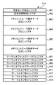
ここで、図14は、本実施形態で用いる、温度差と設定すべきサーマルオフセット値との関係の一例を示す図である。図14に示す関係は、“JESD229 Wide I/O Single Data Rate”として既に規格化されている。図14に示すように、温度差1400(Thermal Gradient)が5℃未満である場合、サーマルオフセット値1401(Thermal Offset)は0に決定される。一方、温度差1400が5〜15℃である場合、サーマルオフセット値1401は1に決定される。
Here, FIG. 14 is a diagram illustrating an example of the relationship between the temperature difference and the thermal offset value to be used, which is used in the present embodiment. The relationship shown in FIG. 14 has already been standardized as “JESD229 Wide I / O Single Data Rate”. As shown in FIG. 14, when the temperature difference 1400 (Thermal Gradient) is less than 5 ° C., the thermal offset value 1401 (Thermal Offset) is determined to be zero. On the other hand, when the
CPU101は、決定したサーマルオフセット値をそれぞれサーマルオフセットレジスタ411〜414に書き込むことで、SDRAM301〜304についてサーマルオフセット値を設定する。
The
<セルフリフレッシュ・モードの設定>
次に、図15を参照して、セルフリフレッシュ・モードの設定処理の手順について説明する。尚、この処理を実行するためのプログラムは、HDD105に予めインストールされている。この処理は、CPU101がHDD105からSDRAM301にプログラムを展開し、展開したプログラムを実行することによって、MFP100上で実現される。図15に示す処理は、WideIO−SDRAM113のSDRAM301〜304のそれぞれをセルフリフレッシュ状態にする際に、CPU101によって実行される。以下ではSDRAM301について説明するが、CPU101は、SDRAM302〜304についても同様の処理を実行する。
<Setting the self-refresh mode>
Next, the procedure for setting the self-refresh mode will be described with reference to FIG. Note that a program for executing this process is installed in the
まずS1501で、CPU101は、メモリコントローラ305によって、レジスタ314内のメモリコントローラ動作モード設定レジスタ403についての確認を行う。具体的には、CPU101は、メモリコントローラ動作モード設定レジスタ403に格納された設定値に基づいて、メモリコントローラ305の動作モードがセルフリフレッシュ・モードに設定されているか否かを判定する。ここで、メモリコントローラ305がセルフリフレッシュ・モードに設定されていない場合、CPU101は、S1501の判定処理を繰り返す。一方、メモリコントローラ305がセルフリフレッシュ・モードに設定されている場合、CPU101は、処理をS1502に進める。
First, in step S <b> 1501, the
S1502で、CPU101は、メモリコントローラ305が待機状態(アイドル状態)であるか否かを判定する。何らかのデータ処理を行っており、メモリコントローラ305が待機状態ではない場合、CPU101は、S1502の判定処理を繰り返す。一方、メモリコントローラ305が待機状態である場合、処理をS1503へ進める。
In step S1502, the
S1503で、CPU101は、サーマルオフセット値を含むサーマルオフセット設定コマンドを、メモリコントローラ305からSDRAM301に対して発行させる。サーマルオフセット設定コマンドには、サーマルオフセットレジスタ411に格納されている設定値が含まれている。
In step S1503, the
次に、S1504で、CPU101は、SDRAM301内に格納されたサーマルオフセット値の設定値を読み出すためのコマンドを、メモリコントローラ305からSDRAM301に対して発行させる。その結果、メモリコントローラ305は、読み出した値を、レジスタ314内のサーマルオフセットステータスレジスタ407に書き込む。これにより、S1503でSDRAM301に設定しようとしたサーマルオフセット値が、正しいか否かを確認できる。
Next, in step S <b> 1504, the
設定されたサーマルオフセット値が正しいことが確認されると、S1505で、CPU101は、セルフリフレッシュ設定コマンドを、メモリコントローラ305からSDRAM301に発行させる。これにより、CPU101は、SDRAM301をセルフリフレッシュ・モードに移行(セルフリフレッシュ状態に移行)させる。即ち、CPU101は、設定されているサーマルオフセット値に対応したリフレッシュ周期で、SDRAM301にリフレッシュ動作を実行させる。
If it is confirmed that the set thermal offset value is correct, in step S1505, the
なお、S1503、S1504及びS1505で発行される各コマンドに関連するプロトコルは、“JESD229 Wide I/O Single Data Rate”として既に規格化されている。 Note that the protocol related to each command issued in S1503, S1504, and S1505 has already been standardized as “JESD229 Wide I / O Single Data Rate”.
以上説明したように、本実施形態に係るMFP100は、予め実行される解析によって生成された既定温度情報と、温度センサ309〜312によって得られた温度情報とに基づいて、メモリチップ内の現在の温度分布を示す温度分布情報(更新温度情報)を生成する。既定温度情報は、SOCダイ201及びWideIO−SDRAM113の動作状況に対応した、メモリチップ内の温度分布に関する情報を含んでいる。MFP100は、更に、更新温度情報が示す温度分布に含まれる、温度センサ309〜312の位置における温度と、メモリチップ内のホットスポットにおける温度との差分に応じて、メモリチップのリフレッシュ動作に用いるサーマルオフセット値を設定する。
As described above, the
本実施形態によれば、SOCダイ201及びWideIO−SDRAM113の動作状況に応じたメモリチップ内の温度分布の変化を、精度良く推定することが可能である。更に、推定した温度分布に応じて、サーマルオフセット値をより適切に設定することが可能である。このように、サーマルオフセット値を適切に設定することで、ホットスポットと温度センサの位置の温度差に起因した、消費電力の増大やメモリチップの記憶内容の消失を防ぐことが可能である。
According to the present embodiment, it is possible to accurately estimate a change in the temperature distribution in the memory chip according to the operating conditions of the SOC die 201 and the WideIO-
また、本実施形態に係るMFP100では、SOCダイ201及びWideIO−SDRAM113の動作状況に応じて、更新温度情報を適切な更新間隔で更新し、更新後の更新温度情報に基づいて、サーマルオフセット値の設定を定期的に実行してもよい。これにより、SOCダイ201及びWideIO−SDRAM113の動作状況の変化に合わせて、サーマルオフセット値を適切に制御して使用することが可能である。
Further, in the
[第2の実施形態]
第1の実施形態では、SOCダイ201及びWideIO−SDRAM113の動作状況の変化に合わせて、予め設定された更新間隔で更新温度情報を更新する場合について説明している。この場合、更新温度情報を更新する際に、実際のメモリチップ(SDRAM301〜304)内の温度分布と、更新温度情報が示す温度分布との間に誤差が生じている可能性がある。第2の実施形態では、このような誤差が生じた場合にもサーマルオフセット値を適切に行うことを可能にする例について説明する。なお、以下では、説明の簡略化のため、第1の実施形態と共通する部分については説明を省略し、主に第1の実施形態と異なる部分を説明する。
[Second Embodiment]
In the first embodiment, a case has been described in which the update temperature information is updated at preset update intervals in accordance with changes in the operating conditions of the SOC die 201 and the WideIO-
<更新温度情報(温度分布情報)の生成及び更新>
図16を参照して、本実施形態における更新温度情報の生成及び更新処理の手順について説明する。尚、この処理を実行するためのプログラムは、HDD105に予めインストールされている。この処理は、CPU101がHDD105からSDRAM301にプログラムを展開し、展開したプログラムを実行することによって、MFP100上で実現される。以下ではSDRAM301について処理を説明するが、CPU101は、SDRAM302〜304についても同様の処理を実行する。
<Generation and update of updated temperature information (temperature distribution information)>
With reference to FIG. 16, the procedure of the production | generation and update process of the update temperature information in this embodiment is demonstrated. Note that a program for executing this process is installed in the
図16では、第1の実施形態(図10)と同一の処理を実行するステップ(S1001〜S1011)に第1の実施形態と同一の参照符号を付している。本実施形態では、更新温度情報が既に生成されている場合、CPU101は、S1008で初期温度を導出した後、処理をS1601に進める。
In FIG. 16, steps (S1001 to S1011) for executing the same processing as in the first embodiment (FIG. 10) are denoted by the same reference numerals as in the first embodiment. In the present embodiment, if the updated temperature information has already been generated, the
S1601で、CPU101は、S1007(図12)と同様の処理によって、温度センサ309から、当該温度センサの位置におけるSDRAM301の温度を示す温度情報を取得する。更に、S1602で、CPU101は、S1601で取得した温度情報が示す温度と、S1008で取得した更新温度情報に含まれる温度情報が示す、温度センサ309の位置における温度(初期温度)との差分を計算し、所定の閾値を上回るか否かを判定する。所定の閾値は、更新温度情報に含まれる、温度センサ309の位置における温度と実際の温度との誤差を評価するために予め設定される閾値である。本実施形態では、当該誤差が比較的大きい場合には、サーマルオフセット値を、更新温度情報に基づいて設定せず、取り得る値のうちの最大値に設定する。
In S1601, the
S1602で、CPU101は、計算した差分が所定の閾値以下であると判定した場合、処理をS1603へ進め、計算した差分が所定の閾値を上回ると判定した場合、処理をS1604へ進める。S1604では、CPU101は、サーマルオフセット・ワーストフラグ(Worstflag)を「true」に設定する。当該フラグは、「true」の場合、更新温度情報の内容によらず、サーマルオフセット値を、取り得る値のうちの最大値に強制的に設定すべきことを示す。
If the
一方、S1603では、CPU101は、S1602で計算した差分に応じて、生成または前回更新された更新温度情報を補正する。具体的には、CPU101は、生成または前回更新された更新温度情報に含まれる、SDRAM301の各領域の温度(更新温度)に、S1602で計算した差分をそれぞれ加算する。
On the other hand, in S1603, the
図18は、S1603における補正前後の更新温度情報の内容の一例を示す図である。温度センサ309の値1800は、温度センサ309から取得された温度情報が示す温度であり、温度センサ309が位置する領域(4,5)の温度は52℃である。補正前の更新温度1801は、S1008で参照した更新温度情報に含まれる、各領域(X,Y)の更新温度であり、温度センサ309が位置する領域(4,5)の温度は48℃である。このように、更新温度情報に含まれる、温度センサ309の位置における温度は、実際の温度に対して+4℃の誤差が生じている。このため、S1603では、CPU101は、更新温度情報に含まれる、全ての領域の更新温度に対して+4℃を加算することで、図18で補正後の更新温度1802として示すように更新温度情報を補正する。
FIG. 18 is a diagram illustrating an example of the content of the updated temperature information before and after correction in S1603. The
本実施形態では、S1009及びS1010において、既に生成されている更新温度情報を更新する場合には、CPU101は、S1603による補正後の更新温度情報を用いた処理を実行する。
In this embodiment, when updating the update temperature information that has already been generated in S1009 and S1010, the
<サーマルオフセット値の設定>
次に、図17のフローチャートを参照して、本実施形態におけるサーマルオフセット値の設定処理の手順について説明する。尚、この処理を実行するためのプログラムは、HDD105に予めインストールされている。この処理は、CPU101がHDD105からSDRAM301にプログラムを展開し、展開したプログラムを実行することによって、MFP100上で実現される。
<Setting of thermal offset value>
Next, the procedure of the thermal offset value setting process in this embodiment will be described with reference to the flowchart of FIG. Note that a program for executing this process is installed in the
図17に示す処理は、第1の実施形態(図13)と同様、MFP100が電源オフ状態から起動する際に実行される、一連の起動シーケンスにおいて最初に実行されるとともに、その後は定期的に実行され続ける。また、図17に示す処理は、SDRAM301〜304のそれぞれについて実行される。ここでは、SDRAM301についての処理を説明するが、SDRAM302〜304についての処理も同様である。
The process shown in FIG. 17 is first executed in a series of startup sequences executed when the
まず、S1701では、CPU101は、SDRAM301について、図16に示す手順に従って、更新温度情報の生成(更新)処理を実行する。
First, in S <b> 1701, the
次に、S1702で、CPU101は、サーマルオフセット・ワーストフラグ(Worstflag)が設定されているか(即ち、「true」に設定されているか)否かを判定する。CPU101は、当該フラグが設定されていない(「false」に設定されている)と判定した場合、処理をS1703へ進め、当該フラグが設定されている(「true」に設定されている)と判定した場合、処理をS1704に進める。
In step S <b> 1702, the
S1703で、CPU101は、S1302と同様、S1701で生成または更新された更新温度情報に基づいて、温度センサ309〜312の位置における温度と、ホットスポットにおける温度とを比較して、それらの差分(温度差)を導出する。例えば、更新温度情報が図18に示す情報である場合、温度センサ309が位置する領域(4,5)における(補正後の)温度が52℃(温度情報1811)、ホットスポットに相当する領域(7,7)における(補正後の)温度が64℃(温度情報1812)である。この場合、温度差として12℃が導出される。
In S1703, as in S1302, the
S1703の後、S1704で、CPU101は、S1703で導出した温度差に応じて、SDRAM301について、リフレッシュ動作に用いるサーマルオフセット値を、S1303と同様に設定し、処理を終了する。一方、S1702からS1704に処理を進めた場合、CPU101は、更新温度情報によらず、サーマルオフセット値を、取り得る値のうちの最大値(図14の場合「1」)に設定し、処理を終了する。
After S1703, in S1704, in accordance with the temperature difference derived in S1703, the
<セルフリフレッシュ・モードの設定>
本実施形態におけるセルフリフレッシュ・モードの設定処理は、第1の実施形態(図15)と同様である。
<Setting the self-refresh mode>
The self-refresh mode setting process in this embodiment is the same as that in the first embodiment (FIG. 15).
以上説明したように、本実施形態では、温度センサ309〜312が位置する領域における、更新温度情報が示す温度と実際の温度との差分を計算し、計算した差分に応じて、更新温度情報の補正またはサーマルオフセット値の設定を行う。具体的には、計算した差分が所定の閾値以下である場合には、当該差分に応じて更新温度情報を補正する。これにより、更新温度情報に生じた誤差を適切に補正して、より精度よくサーマルオフセット値の設定を行うことが可能である。また、計算した差分が所定の閾値を上回る場合には、サーマルオフセット値を強制的に、取り得る値のうちの最大値に設定する。これにより、更新温度情報に大幅に誤差が生じた場合にも、ホットスポットに起因したメモリチップの記憶内容の消失を極力防ぐことが可能である。
As described above, in the present embodiment, the difference between the temperature indicated by the update temperature information and the actual temperature in the region where the
[その他の実施形態]
また、本発明は、以下の処理を実行することによっても実現される。即ち、上述した実施形態の機能を実現するソフトウェア(プログラム)を、ネットワークまたは各種記憶媒体を介してシステム或いは装置に供給し、そのシステム或いは装置のコンピュータ(またはCPUやMPU等)がプログラムを読み出して実行する処理である。
[Other Embodiments]
The present invention can also be realized by executing the following processing. That is, software (program) that realizes the functions of the above-described embodiments is supplied to a system or apparatus via a network or various storage media, and a computer (or CPU, MPU, etc.) of the system or apparatus reads the program. It is a process to be executed.
Claims (18)
前記WideIOメモリデバイスに含まれるメモリチップに設けられた温度センサから、前記温度センサの位置における前記メモリチップの温度を示すセンサ情報を取得する取得手段と、
予め実行される解析によって生成された、前記メモリチップ内の温度分布に関する情報を含む既定温度情報であって、前記SOCダイ及び前記WideIOメモリデバイスの動作状況に対応する前記既定温度情報と、前記取得手段によって取得されたセンサ情報とに基づいて、前記メモリチップ内の現在の温度分布を示す温度分布情報を生成する生成手段と、
前記温度分布情報が示す温度分布に含まれる、前記温度センサの位置における温度と、前記メモリチップ内で最も温度が高くなっている位置における温度との差分に応じて、前記メモリチップのリフレッシュ動作に用いるサーマルオフセット値を設定する設定手段と
を備えることを特徴とする情報処理装置。 An information processing apparatus comprising a WideIO memory device stacked on an SOC die including a CPU,
Obtaining means for obtaining sensor information indicating a temperature of the memory chip at a position of the temperature sensor from a temperature sensor provided in a memory chip included in the WideIO memory device;
Pre-determined temperature information generated by a pre-executed analysis and including information related to a temperature distribution in the memory chip, the predetermined temperature information corresponding to operating states of the SOC die and the WideIO memory device, and the acquisition Generating means for generating temperature distribution information indicating the current temperature distribution in the memory chip based on the sensor information acquired by the means;
The refresh operation of the memory chip is performed according to the difference between the temperature at the position of the temperature sensor included in the temperature distribution indicated by the temperature distribution information and the temperature at the highest temperature position in the memory chip. An information processing apparatus comprising: setting means for setting a thermal offset value to be used.
前記SOCダイが特定の動作を開始した後の、前記SOCダイ及び前記WideIOメモリデバイスの動作状況に対応した、前記メモリチップ内の温度分布の時間変化を示す情報を含み、
前記生成手段は、
前記既定温度情報が示す、前記温度センサの位置における、前記特定の動作に応じた前記メモリチップの温度の変化と、前記センサ情報が示す温度とを比較することで、前記SOCダイが前記特定の動作を開始してからの経過時間を特定するとともに、
前記経過時間に対応する前記メモリチップ内の温度分布を示す情報を、前記温度分布情報として生成する
ことを特徴とする請求項1または2に記載の情報処理装置。 The predetermined temperature information is:
Including information indicating a time change of a temperature distribution in the memory chip corresponding to an operating state of the SOC die and the WideIO memory device after the SOC die starts a specific operation;
The generating means includes
By comparing the change in the temperature of the memory chip according to the specific operation at the position of the temperature sensor indicated by the predetermined temperature information with the temperature indicated by the sensor information, the SOC die In addition to specifying the elapsed time since the start of operation,
The information processing apparatus according to claim 1, wherein information indicating a temperature distribution in the memory chip corresponding to the elapsed time is generated as the temperature distribution information.
前記SOCダイが前記特定の動作を開始してから、前記温度センサの位置における前記メモリチップの温度が、前記特定の動作に応じて、前記センサ情報が示す温度に変化するまでの時間を、前記経過時間として特定することを特徴とする請求項3に記載の情報処理装置。 The generating means includes
The time from when the SOC die starts the specific operation until the temperature of the memory chip at the position of the temperature sensor changes to the temperature indicated by the sensor information according to the specific operation, The information processing apparatus according to claim 3, wherein the information processing apparatus is specified as an elapsed time.
前記メモリチップ内を複数の領域に分割して得られる各領域についての、前記SOCダイが前記特定の動作を開始した後の、異なる複数の時点における温度を示す情報を含み、
前記生成手段は、
前記複数の領域のそれぞれについて、前記既定温度情報に含まれる、前記複数の時点における温度から、前記SOCダイの前記特定の動作に応じた温度の変化を表す近似曲線を計算するとともに、
前記温度センサが含まれる領域について計算した前記近似曲線に基づいて、前記経過時間を特定する
ことを特徴とする請求項3または4に記載の情報処理装置。 The predetermined temperature information is:
For each region obtained by dividing the inside of the memory chip into a plurality of regions, including information indicating temperatures at different points in time after the SOC die starts the specific operation,
The generating means includes
For each of the plurality of regions, an approximate curve representing a change in temperature according to the specific operation of the SOC die is calculated from the temperatures at the plurality of time points included in the predetermined temperature information,
The information processing apparatus according to claim 3, wherein the elapsed time is specified based on the approximate curve calculated for a region including the temperature sensor.
前記設定手段は、前記生成手段によって生成された、または前記更新手段によって更新された前記温度分布情報に基づいて、前記サーマルオフセット値の設定を定期的に実行する
ことを特徴とする請求項1乃至6のいずれか1項に記載の情報処理装置。 Updating means for updating the temperature distribution information generated by the generating means based on the predetermined temperature information at a preset update interval;
The setting unit periodically executes the setting of the thermal offset value based on the temperature distribution information generated by the generating unit or updated by the updating unit. The information processing apparatus according to any one of 6.
前記生成手段によって生成された、または前回更新した前記温度分布情報に含まれる、前記温度センサの位置における温度を基準として、前記SOCダイ及び前記WideIOメモリデバイスの動作状況に対応する前記既定温度情報に基づいて前記温度分布情報を更新することを特徴とする請求項7に記載の情報処理装置。 The updating means includes
The predetermined temperature information corresponding to the operating state of the SOC die and the WideIO memory device with reference to the temperature at the position of the temperature sensor included in the temperature distribution information generated by the generating unit or updated last time. The information processing apparatus according to claim 7, wherein the temperature distribution information is updated based on the information.
前記更新手段によって更新された前記温度分布情報に含まれる、前記温度センサの位置における温度と、前記センサ情報が示す温度との差分が、所定の閾値を上回ると、前記サーマルオフセット値を、取り得る値のうちの最大値に設定することを特徴とする請求項7または8に記載の情報処理装置。 The setting means includes
When the difference between the temperature at the position of the temperature sensor included in the temperature distribution information updated by the updating unit and the temperature indicated by the sensor information exceeds a predetermined threshold, the thermal offset value can be obtained. The information processing apparatus according to claim 7, wherein the information processing apparatus is set to a maximum value among the values.
前記温度分布情報が示す温度分布に含まれる、前記温度センサの位置における温度と、前記メモリチップ内で最も温度が高くなっている位置における温度との差分が大きいほど、前記サーマルオフセット値を大きな値に設定することを特徴とする請求項1乃至10のいずれか1項に記載の情報処理装置。 The setting means includes
The larger the difference between the temperature at the position of the temperature sensor included in the temperature distribution indicated by the temperature distribution information and the temperature at the highest temperature position in the memory chip, the larger the thermal offset value. The information processing apparatus according to any one of claims 1 to 10, wherein the information processing apparatus is set.
前記生成手段は、前記複数のチップ領域のそれぞれについて、個別に前記温度分布情報を生成し、
前記設定手段は、前記複数のチップ領域のそれぞれについて、個別に前記サーマルオフセット値を設定する
ことを特徴とする請求項1乃至11のいずれか1項に記載の情報処理装置。 The memory chip is used by being divided into a plurality of chip regions corresponding to each of a plurality of memory channels included in the WideIO memory device and individually provided with the temperature sensor,
The generating means generates the temperature distribution information individually for each of the plurality of chip regions,
The information processing apparatus according to claim 1, wherein the setting unit individually sets the thermal offset value for each of the plurality of chip regions.
前記メモリチップをセルフリフレッシュ状態に移行させる場合には、前記設定手段によって設定されている前記サーマルオフセット値に対応したリフレッシュ周期で、前記メモリチップに前記リフレッシュ動作を実行させることを特徴とする請求項1乃至14のいずれか1項に記載の情報処理装置。 The CPU
The memory chip is caused to execute the refresh operation in a refresh cycle corresponding to the thermal offset value set by the setting means when the memory chip is shifted to a self-refresh state. The information processing apparatus according to any one of 1 to 14.
前記情報処理装置が電源オフ状態から起動するごとに、前記温度分布情報を初期化して新たに生成することを特徴とする請求項1乃至15のいずれか1項に記載の情報処理装置。 The generating means includes
The information processing apparatus according to any one of claims 1 to 15, wherein the temperature distribution information is initialized and newly generated every time the information processing apparatus is started from a power-off state.
取得手段が、前記WideIOメモリデバイスに含まれるメモリチップに設けられた温度センサから、前記温度センサの位置における前記メモリチップの温度を示すセンサ情報を取得する取得工程と、
生成手段が、予め実行される解析によって生成された、前記メモリチップ内の温度分布に関する情報を含む既定温度情報であって、前記SOCダイ及び前記WideIOメモリデバイスの動作状況に対応する前記既定温度情報と、前記取得工程で取得されたセンサ情報とに基づいて、前記メモリチップ内の現在の温度分布を示す温度分布情報を生成する生成工程と、
設定手段が、前記温度分布情報が示す温度分布に含まれる、前記温度センサの位置における温度と、前記メモリチップ内で最も温度が高くなっている位置における温度との差分に応じて、前記メモリチップのリフレッシュ動作に用いるサーマルオフセット値を設定する設定工程と
を有することを特徴とする情報処理装置の制御方法。 A method for controlling an information processing apparatus including a WideIO memory device stacked on an SOC die including a CPU,
An obtaining step for obtaining sensor information indicating a temperature of the memory chip at a position of the temperature sensor from a temperature sensor provided in a memory chip included in the WideIO memory device;
The predetermined temperature information including information related to the temperature distribution in the memory chip, which is generated by an analysis performed in advance by the generation unit, and the predetermined temperature information corresponding to the operating state of the SOC die and the WideIO memory device And a generation step of generating temperature distribution information indicating a current temperature distribution in the memory chip based on the sensor information acquired in the acquisition step;
In accordance with the difference between the temperature at the position of the temperature sensor included in the temperature distribution indicated by the temperature distribution information and the temperature at the highest temperature position in the memory chip, the setting unit And a setting step for setting a thermal offset value used for the refresh operation of the information processing apparatus.
Priority Applications (3)
| Application Number | Priority Date | Filing Date | Title |
|---|---|---|---|
| JP2012245635A JP6101047B2 (en) | 2012-11-07 | 2012-11-07 | Information processing apparatus, control method therefor, and program |
| PCT/JP2013/080058 WO2014073584A1 (en) | 2012-11-07 | 2013-10-30 | Information processing apparatus, method for controlling the same and program |
| US14/374,506 US9703298B2 (en) | 2012-11-07 | 2013-10-30 | Information processing apparatus, method for controlling the same and program |
Applications Claiming Priority (1)
| Application Number | Priority Date | Filing Date | Title |
|---|---|---|---|
| JP2012245635A JP6101047B2 (en) | 2012-11-07 | 2012-11-07 | Information processing apparatus, control method therefor, and program |
Publications (3)
| Publication Number | Publication Date |
|---|---|
| JP2014096188A JP2014096188A (en) | 2014-05-22 |
| JP2014096188A5 JP2014096188A5 (en) | 2015-12-24 |
| JP6101047B2 true JP6101047B2 (en) | 2017-03-22 |
Family
ID=50684686
Family Applications (1)
| Application Number | Title | Priority Date | Filing Date |
|---|---|---|---|
| JP2012245635A Expired - Fee Related JP6101047B2 (en) | 2012-11-07 | 2012-11-07 | Information processing apparatus, control method therefor, and program |
Country Status (3)
| Country | Link |
|---|---|
| US (1) | US9703298B2 (en) |
| JP (1) | JP6101047B2 (en) |
| WO (1) | WO2014073584A1 (en) |
Families Citing this family (11)
| Publication number | Priority date | Publication date | Assignee | Title |
|---|---|---|---|---|
| US9490003B2 (en) * | 2011-03-31 | 2016-11-08 | Intel Corporation | Induced thermal gradients |
| US9658678B2 (en) | 2011-03-31 | 2017-05-23 | Intel Corporation | Induced thermal gradients |
| US9396787B2 (en) | 2011-12-23 | 2016-07-19 | Intel Corporation | Memory operations using system thermal sensor data |
| JP2014106917A (en) * | 2012-11-29 | 2014-06-09 | Canon Inc | Information processing unit, control method thereof and program |
| JP2015041395A (en) | 2013-08-20 | 2015-03-02 | キヤノン株式会社 | Information processor and control method therefor and program therefor and storage medium |
| JP6425462B2 (en) * | 2014-08-27 | 2018-11-21 | ルネサスエレクトロニクス株式会社 | Semiconductor device |
| US11321008B2 (en) | 2018-11-15 | 2022-05-03 | Micron Technology, Inc. | Temperature-based memory management |
| KR102252572B1 (en) * | 2019-05-14 | 2021-05-17 | 어보브반도체 주식회사 | Grip Sensing Method and Apparatus |
| US11593244B2 (en) * | 2020-02-21 | 2023-02-28 | Dell Products L.P. | System and method for determining physical orientation of a memory module using on-board thermal sensors |
| KR20220062756A (en) * | 2020-11-09 | 2022-05-17 | 삼성전자주식회사 | Memory Device, Storage Module, Host and Operating Methods thereof |
| KR102410958B1 (en) * | 2021-11-15 | 2022-06-22 | 삼성전자주식회사 | Memory module and memory system including the same |
Family Cites Families (21)
| Publication number | Priority date | Publication date | Assignee | Title |
|---|---|---|---|---|
| JP3618884B2 (en) | 1996-03-18 | 2005-02-09 | キヤノン株式会社 | Information processing apparatus, information processing method, printing system, and memory |
| US5784328A (en) * | 1996-12-23 | 1998-07-21 | Lsi Logic Corporation | Memory system including an on-chip temperature sensor for regulating the refresh rate of a DRAM array |
| JP4477429B2 (en) * | 2003-11-05 | 2010-06-09 | 富士通マイクロエレクトロニクス株式会社 | Semiconductor integrated circuit |
| JP3781758B2 (en) * | 2004-06-04 | 2006-05-31 | 株式会社ソニー・コンピュータエンタテインメント | Processor, processor system, temperature estimation device, information processing device, and temperature estimation method |
| US7214910B2 (en) * | 2004-07-06 | 2007-05-08 | International Business Machines Corporation | On-chip power supply regulator and temperature control system |
| US20060236027A1 (en) * | 2005-03-30 | 2006-10-19 | Sandeep Jain | Variable memory array self-refresh rates in suspend and standby modes |
| DE102005025168B4 (en) * | 2005-06-01 | 2013-05-29 | Qimonda Ag | Electronic storage device and method for operating an electronic storage device |
| JP2007250591A (en) * | 2006-03-13 | 2007-09-27 | Toshiba Corp | Temperature control system |
| DE102006018921A1 (en) * | 2006-04-24 | 2007-11-08 | Infineon Technologies Ag | Integrated semiconductor memory with refreshment of memory cells |
| JP5065618B2 (en) * | 2006-05-16 | 2012-11-07 | 株式会社日立製作所 | Memory module |
| US20080284609A1 (en) * | 2007-05-17 | 2008-11-20 | Broadcom Corporation, A California Corporation | RF Integrated circuit having an on-chip thermal sensing circuit |
| US8175545B2 (en) * | 2007-05-17 | 2012-05-08 | Broadcom Corporation | Communication devices with integrated thermal sensing circuit and methods for use therewith |
| TWI470762B (en) * | 2007-07-27 | 2015-01-21 | 尼康股份有限公司 | Laminated semiconductor device |
| KR101007988B1 (en) * | 2008-01-02 | 2011-01-14 | 주식회사 하이닉스반도체 | Thermal data output circuit and multi chip package using the same |
| KR101683814B1 (en) | 2010-07-26 | 2016-12-08 | 삼성전자주식회사 | Semiconductor apparatus having through vias |
| KR101796116B1 (en) * | 2010-10-20 | 2017-11-10 | 삼성전자 주식회사 | Semiconductor device, memory module and memory system having the same and operating method thereof |
| KR101817156B1 (en) * | 2010-12-28 | 2018-01-10 | 삼성전자 주식회사 | Semiconductor device of stacked structure having through electrode, semiconductor memory device, semiconductor memory system and operating method thereof |
| JP5932236B2 (en) | 2011-04-13 | 2016-06-08 | ピーエスフォー ルクスコ エスエイアールエルPS4 Luxco S.a.r.l. | Semiconductor device and system |
| KR101872297B1 (en) * | 2011-05-11 | 2018-07-02 | 에스케이하이닉스 주식회사 | Semiconductor memory apparatus |
| US9396787B2 (en) * | 2011-12-23 | 2016-07-19 | Intel Corporation | Memory operations using system thermal sensor data |
| US9355704B2 (en) * | 2012-12-28 | 2016-05-31 | Mediatek Inc. | Refresh method for switching between different refresh types based on at least one parameter of volatile memory and related memory controller |
-
2012
- 2012-11-07 JP JP2012245635A patent/JP6101047B2/en not_active Expired - Fee Related
-
2013
- 2013-10-30 US US14/374,506 patent/US9703298B2/en not_active Expired - Fee Related
- 2013-10-30 WO PCT/JP2013/080058 patent/WO2014073584A1/en active Application Filing
Also Published As
| Publication number | Publication date |
|---|---|
| WO2014073584A1 (en) | 2014-05-15 |
| JP2014096188A (en) | 2014-05-22 |
| US9703298B2 (en) | 2017-07-11 |
| US20140371945A1 (en) | 2014-12-18 |
Similar Documents
| Publication | Publication Date | Title |
|---|---|---|
| JP6101047B2 (en) | Information processing apparatus, control method therefor, and program | |
| JP2015041395A (en) | Information processor and control method therefor and program therefor and storage medium | |
| US9442551B2 (en) | Information processing apparatus, control method for the same and storage medium | |
| JP2014075002A (en) | Information processor, control method thereof, and program | |
| US7395176B2 (en) | Memory controller for controlling a refresh cycle of a memory and a method thereof | |
| JP2014078128A (en) | Information processor and the control method thereof, and the program thereof and storage medium | |
| US9110707B2 (en) | Assigning wideio memories to functions based on memory access and acquired temperature information | |
| JP2014106917A (en) | Information processing unit, control method thereof and program | |
| US10268257B2 (en) | Memory control device that control semiconductor memory, memory control method, information device equipped with memory control device, and storage medium storing memory control program | |
| JP2014115791A (en) | Information processor, method of controlling the same, and program | |
| JPH11224221A (en) | Unit and method for memory control | |
| US8218389B2 (en) | Semiconductor storage device and control method of the same | |
| JP6274774B2 (en) | Memory interface device and control method thereof | |
| JP2004171678A (en) | Apparatus, method, and program for storing information | |
| US20090070358A1 (en) | Apparatus, method, and computer program product for processing information | |
| JP6041610B2 (en) | Information processing apparatus, control method therefor, program, and storage medium | |
| JP2010124076A (en) | Image processor, control method for image processor, and program of the same | |
| JP2008152315A (en) | Signal processing circuit | |
| US20170153688A1 (en) | Control apparatus for controlling memory and control method for power saving of memory | |
| US11289148B2 (en) | Memory control apparatus and control method therefor | |
| US11604717B2 (en) | Processor performance measurement apparatus and processor performance measurement method | |
| JP4203337B2 (en) | Memory arbiter and memory control device | |
| JP2007115357A (en) | Device and method for recording data | |
| JP3674670B2 (en) | Bus control device and semiconductor device | |
| JP2022164050A (en) | Information processing device and control method for the same |
Legal Events
| Date | Code | Title | Description |
|---|---|---|---|
| A521 | Request for written amendment filed |
Free format text: JAPANESE INTERMEDIATE CODE: A523 Effective date: 20151104 |
|
| A621 | Written request for application examination |
Free format text: JAPANESE INTERMEDIATE CODE: A621 Effective date: 20151104 |
|
| TRDD | Decision of grant or rejection written | ||
| A01 | Written decision to grant a patent or to grant a registration (utility model) |
Free format text: JAPANESE INTERMEDIATE CODE: A01 Effective date: 20170127 |
|
| A61 | First payment of annual fees (during grant procedure) |
Free format text: JAPANESE INTERMEDIATE CODE: A61 Effective date: 20170224 |
|
| R151 | Written notification of patent or utility model registration |
Ref document number: 6101047 Country of ref document: JP Free format text: JAPANESE INTERMEDIATE CODE: R151 |
|
| LAPS | Cancellation because of no payment of annual fees |