JP6100177B2 - Synchronous motor for the operation of pumps and related motor pumps - Google Patents
Synchronous motor for the operation of pumps and related motor pumps Download PDFInfo
- Publication number
- JP6100177B2 JP6100177B2 JP2013558575A JP2013558575A JP6100177B2 JP 6100177 B2 JP6100177 B2 JP 6100177B2 JP 2013558575 A JP2013558575 A JP 2013558575A JP 2013558575 A JP2013558575 A JP 2013558575A JP 6100177 B2 JP6100177 B2 JP 6100177B2
- Authority
- JP
- Japan
- Prior art keywords
- rotor
- cylindrical element
- pump
- electric motor
- cavity
- Prior art date
- Legal status (The legal status is an assumption and is not a legal conclusion. Google has not performed a legal analysis and makes no representation as to the accuracy of the status listed.)
- Expired - Fee Related
Links
Images


Classifications
-
- F—MECHANICAL ENGINEERING; LIGHTING; HEATING; WEAPONS; BLASTING
- F04—POSITIVE - DISPLACEMENT MACHINES FOR LIQUIDS; PUMPS FOR LIQUIDS OR ELASTIC FLUIDS
- F04D—NON-POSITIVE-DISPLACEMENT PUMPS
- F04D13/00—Pumping installations or systems
- F04D13/02—Units comprising pumps and their driving means
- F04D13/06—Units comprising pumps and their driving means the pump being electrically driven
- F04D13/0606—Canned motor pumps
- F04D13/064—Details of the magnetic circuit
-
- F—MECHANICAL ENGINEERING; LIGHTING; HEATING; WEAPONS; BLASTING
- F04—POSITIVE - DISPLACEMENT MACHINES FOR LIQUIDS; PUMPS FOR LIQUIDS OR ELASTIC FLUIDS
- F04D—NON-POSITIVE-DISPLACEMENT PUMPS
- F04D29/00—Details, component parts, or accessories
- F04D29/04—Shafts or bearings, or assemblies thereof
- F04D29/046—Bearings
- F04D29/047—Bearings hydrostatic; hydrodynamic
-
- H—ELECTRICITY
- H02—GENERATION; CONVERSION OR DISTRIBUTION OF ELECTRIC POWER
- H02K—DYNAMO-ELECTRIC MACHINES
- H02K9/00—Arrangements for cooling or ventilating
- H02K9/19—Arrangements for cooling or ventilating for machines with closed casing and closed-circuit cooling using a liquid cooling medium, e.g. oil
- H02K9/193—Arrangements for cooling or ventilating for machines with closed casing and closed-circuit cooling using a liquid cooling medium, e.g. oil with provision for replenishing the cooling medium; with means for preventing leakage of the cooling medium
Landscapes
- Engineering & Computer Science (AREA)
- Mechanical Engineering (AREA)
- General Engineering & Computer Science (AREA)
- Physics & Mathematics (AREA)
- Fluid Mechanics (AREA)
- Power Engineering (AREA)
- Structures Of Non-Positive Displacement Pumps (AREA)
- Connection Of Motors, Electrical Generators, Mechanical Devices, And The Like (AREA)
- Motor Or Generator Frames (AREA)
Description
本発明は、ポンプの動作のための同期電動機に関する。 The present invention relates to a synchronous motor for the operation of a pump.
本発明はまた、ポンプに連結された同期電動機を備える電動機ポンプに関する。 The invention also relates to a motor pump comprising a synchronous motor coupled to the pump.
水槽用のポンプ、例えば洗濯機および食器洗い機などの家電製品用ポンプなどのポンプの動作のために同期電動機を使用することは周知である。 It is well known to use synchronous motors for the operation of pumps for aquariums, for example pumps for household appliances such as washing machines and dishwashers.
同期電動機は、固定子および回転子をその中に収容する電動機本体を備える。 The synchronous motor includes a motor body that houses a stator and a rotor therein.
固定子は、通常磁石の積層体の積み重ねであり、1つ以上の電気的な巻き線がその上に巻かれている固定子パックを備える。固定子パックは、回転子がその内側に位置する、少なくとも2つの磁極片を有する。次いで、固定子は電動機の誘導子を形成する。 The stator is usually a stack of magnet stacks and comprises a stator pack on which one or more electrical windings are wound. The stator pack has at least two pole pieces on which the rotor is located. The stator then forms the inductor of the motor.
回転子は、通常円筒形の永久磁石からなり、電動機の電機子を構成する。 The rotor is usually composed of a cylindrical permanent magnet and constitutes an armature of the motor.
電気的な巻き線に電力を供給することによって、固定子パックに磁束が生成され、したがって磁極片において磁極が生成され、これが回転子の磁界と相互作用して、ひいては回転子の回転を起こす。 By supplying power to the electrical windings, magnetic flux is generated in the stator pack, and thus magnetic poles are generated in the pole pieces, which interact with the rotor magnetic field and thus cause rotation of the rotor.
回転子は、通常中央に穴があいており、その内側にシャフトが強固に挿入されかつ固定される。シャフトは、その2つの端部において、電動機本体内に形成された空洞の内側に強固に取り付けられたそれぞれのブッシュによって支持される。ポンプの羽根車は、シャフトの2つの端部のうちの1つに固定される。 The rotor usually has a hole in the center, and the shaft is firmly inserted and fixed inside thereof. The shaft is supported at its two ends by respective bushings that are firmly attached inside the cavity formed in the motor body. The impeller of the pump is fixed to one of the two ends of the shaft.
図1に示すような先行技術のいくつかの電動機では、固定子部分を回転子部分から絶縁するために円筒要素が使用され、これにより固定子の電気的な巻き線が送出される液体に接触するのを妨げる。この図では、ポンプ50に連結された電動機20を備える先行技術の電動機ポンプ10が示される。
In some prior art motors, such as shown in FIG. 1, a cylindrical element is used to insulate the stator portion from the rotor portion, so that the stator electrical windings contact the liquid being delivered. Prevent you from doing. In this figure, a prior art
電動機20は、壁によって区切られた電動機本体22を備える。円筒要素24は、電動機本体22の上壁22Aから開始して内側に向かって延在し、2つの端部、すなわち、壁22Aに面し、外側にむかって開く第1の端部24aと、電動機本体22の内側に面し、底部26によって閉止される第2の端部24bとを有する。したがって、円筒要素24は、2つの空洞、すなわち円筒要素24の内側の第1の空洞28と、円筒要素24の外側であるが、電動機本体22の内側に含まれる第2の空洞30とを画定する。
The
磁石を含む回転子32は、第1の空洞28内に収容されるが、一方で固定子は、第2の空洞30内に収容され、その磁極片34が、図1に示される。
The
回転子32は、回転子32の中心に作成された穴の内側に挿入されかつ固定される、シャフト36を備える。シャフト36は、2つの端部、すなわちポンプ50の羽根車52がその上に固定される第1の端部36aと、円筒要素24の底部26の上に形成される座26aの内側に収容される第2の端部36bとを有する。
The
シャフト36の回転子32と羽根車52との間の部分は、ブッシュ38内に挿入され、シャフト36は自由に回転できる。ブッシュ38は、円筒要素24の内側に、ガスケット40(例えば、Oリング)によって固定される。
The portion of the
ポンプ50は、電動機本体22の上に載置されたポンプ本体54を備え、羽根車52はその内側に収容される。
The
固定子の電気的な巻き線に電力を供給することによって、磁極片34において磁極が生成され、回転子磁石32の磁界と相互作用することにより、これは回転子32に回転を与え、したがって羽根車52にも回転を与える。
By supplying power to the stator's electrical windings, a magnetic pole is created in the
示されるように、円筒要素24のおかげで、固定子を収容する第2の空洞30は、完全に閉鎖され、したがって電気的な巻き線は完全に絶縁される。
この出願の発明に関連する先行技術文献情報としては、以下のものがある(国際出願日以降国際段階で引用された文献及び他国に国内移行した際に引用された文献を含む)。
(先行技術文献)
(特許文献)
(特許文献1) 独国特許出願公開第1811430号明細書
(特許文献2) 仏国追加特許発明第69944号明細書
As shown, thanks to the
Prior art document information related to the invention of this application includes the following (including documents cited in the international phase after the international filing date and documents cited when entering the country in other countries).
(Prior art documents)
(Patent Literature)
(Patent Document 1) German Patent Application Publication No. 1811430
(Patent Document 2) French Patent Additive Patent No. 69944 Specification
しかしながら、まさに記述したこの先行技術の実施形態は、いくつかの欠点を有する。 However, this prior art embodiment just described has several disadvantages.
まず最初に、回転子から羽根車へ運動を伝達するためのシャフト、シャフトをその内側に挿入し固定する穴付きの回転子、シャフトの一端を支持するためのブッシュ、およびシャフトの他端を支持するための筐体座を構築しなければならないため、この実施形態は大変複雑である。加えて、これらの要素すべてを構築した後、これらを互いに載置する必要がある。次いで、個々の部品を得るための製造コスト、およびこれらの組み立てコストの両方が高価である。 First, a shaft for transmitting motion from the rotor to the impeller, a rotor with a hole for inserting and fixing the shaft inside, a bush for supporting one end of the shaft, and supporting the other end of the shaft This embodiment is very complicated because a housing seat must be constructed. In addition, after all these elements have been constructed, they need to be mounted on each other. Then, both the manufacturing costs for obtaining the individual parts and their assembly costs are expensive.
次いで、時間とともに、および摩耗に起因して、一部の構成要素は故障する場合があり、かつ電動機ポンプの正しい動作を中断する場合があることは避けられず、特別な人員の介入のためのコストも必要になる。 Then, over time and due to wear, it is inevitable that some components may fail and may interrupt the correct operation of the electric pump, for special personnel intervention Cost is also required.
特に、ガスケット40は、ポンプ本体と接触するので、場合によっては汚れており、または攻撃的でさえある、送出される流体とも接触する。事実、洗濯機の排水は、ガスケットを容易に攻撃し、浸食する、化学的に攻撃的な洗剤を含み、したがってこれらを頻繁に交換しなければならず、明白に不便を生じる。
In particular, because the
さらに、第1の円筒空洞28と回転子32との間に、空間、すなわち空気室が画定され、これはより詳細には回転子32と円筒要素24の底部26との間の第1の空気室と、回転子32とブッシュ38との間の第2の空気室とである。
In addition, a space, i.e., an air chamber, is defined between the first
次いで、第2の空気室は、円筒要素24と回転子32との間に画定された空間を通して相互に連通する。
The second air chamber then communicates with each other through a space defined between the
これらの空気室は、
電動機の絶え間ない起動および停止と、
送出される液体の温度の変動(例えば、洗濯機または食器洗い機の電動機ポンプの場合、液体は、室温か、加熱されているかのいずれかである可能性がある)と、
に起因して、羽根車本体に含まれる液体を吸い込むミニポンプとして機能することが、出願者らによって確立された。しかし、ガスケット40が使用されるという事実にもかかわらず、上記のように、シールが摩耗することおよび送出される液体により攻撃されることに特に考慮しなければならない場合、これらの空気室は、羽根車本体に含まれる液体を吸い込む可能性がある。
These air chambers
With constant start and stop of the motor,
Fluctuations in the temperature of the delivered liquid (for example, in the case of a washing machine or dishwasher electric pump, the liquid may be either room temperature or heated);
Due to the above, it has been established by the applicants that it functions as a mini pump that sucks in the liquid contained in the impeller body. However, in spite of the fact that
したがって、洗剤、洗浄剤などの液体に含まれる不純物、および洗濯機または食器洗い機のための電動機ポンプの場合の様々な不純物は、回転子を収容する空洞の内側に入り込み、時間とともに蓄積し、空洞の内側の回転子の正しい回転を妨げ、ひいては回転子に、詰まりまたは修理不可能な損傷を生じさせる。 Therefore, impurities contained in liquids such as detergents, cleaning agents, and various impurities in the case of an electric motor pump for a washing machine or dishwasher, enter inside the cavity containing the rotor and accumulate over time, Prevents proper rotation of the inner rotor of the rotor and thus causes clogging or irreparable damage to the rotor.
これは、電動機の停止に起因する問題を生じさせ、その結果、損傷した電動機ポンプの保守またはさらには交換のために、高いコストが発生する。 This creates problems due to motor shutdown, resulting in high costs for maintenance or even replacement of damaged motor pumps.
本発明の目的は、引用した先行技術を参照して上述した欠点を除去することであり、特に電動機を形成する様々な構成要素の急速な摩耗を回避することであるが、特には、空洞内に入り込む可能性がある不純物に起因して、回転子が正しくなく機能すること、またはさらに詰まる、または故障することを避けることである。 The object of the present invention is to eliminate the disadvantages mentioned above with reference to the cited prior art, in particular to avoid rapid wear of the various components forming the motor, but in particular in the cavity. It is to avoid the rotor from functioning improperly, or even clogging or failing due to impurities that can get into.
これらの目的は、請求項1による電動機ポンプによって達成される。 These objects are achieved by an electric motor pump according to claim 1.
このようにして、先行技術の電動機と比較すると、駆動シャフトがなく、シャフトを挿入するために回転子に穴をあける必要がなく、シャフトの端部がその中で回転する、ブッシュまたは他の支持体を構築する必要がないので、電動機の構築設計は、相当に単純化される。 In this way, compared to prior art motors, there is no drive shaft, there is no need to drill the rotor to insert the shaft, and the end of the shaft rotates within it, a bush or other support Since there is no need to construct a body, the construction design of the motor is considerably simplified.
単に、回転子のみを実現し、これを羽根車に軸方向で直接連結する必要があるだけである。 It is only necessary to realize only the rotor and to connect it directly to the impeller in the axial direction.
事実、少なくともその長さの一部に対して、回転子は、その内側に回転子が収容される円筒要素の円筒形の空洞に対応する部分を有し、回転子は、その内側に回転子が挿入される円筒要素によって直接支持されるので、いかなる支持も必要ないことに留意されたい。 In fact, for at least a part of its length, the rotor has a portion corresponding to the cylindrical cavity of the cylindrical element in which the rotor is housed, and the rotor has a rotor inside it. Note that no support is required since is supported directly by the inserted cylindrical element.
換言すれば、回転子自体がシャフトとして動作し、ブッシュは、回転子がその内側で回転する円筒要素によって置き換えられる。 In other words, the rotor itself acts as a shaft, and the bushing is replaced by a cylindrical element on which the rotor rotates.
この構造の単純さのおかげで、かかる電動機の生産時間は相当短縮され、製造コストも相当抑えられる。 Thanks to the simplicity of this structure, the production time of such an electric motor is considerably shortened and the manufacturing costs are considerably reduced.
さらに、回転子と円筒要素との間の接触部の直径は、先行技術の電動機の駆動シャフトとブッシュとの間の接触部の直径よりもずっと大きく、したがって接触面はずっと広い。 Furthermore, the diameter of the contact between the rotor and the cylindrical element is much larger than the diameter of the contact between the drive shaft and the bush of the prior art electric motor, and therefore the contact surface is much wider.
その結果、接触圧力はごく限られ、このため摩耗が著しく低減する。このようにして、電動機の耐用年数は著しく延びる。 As a result, the contact pressure is very limited, so that wear is significantly reduced. In this way, the service life of the motor is significantly increased.
さらに、回転子の長さの少なくとも一部に対して、回転子と円筒要素との間に直接接触があるという事実により、流体は回転子を収容する空洞の内側に入り込むことができない。したがって、回転子は、送出される流体に含まれる不純物に起因する機能不全または詰まりを受ける可能性があるというリスクがない。 Furthermore, due to the fact that there is direct contact between the rotor and the cylindrical element for at least part of the length of the rotor, fluid cannot enter inside the cavity containing the rotor. Thus, there is no risk that the rotor may suffer from malfunctions or clogging due to impurities contained in the delivered fluid.
好ましくは、前記円筒要素内に収容される回転子のすべての部分は、前記円筒要素の内部断面に対応する円形断面を有し、これにより、前記円筒要素の内側に収容される回転子のすべての部分は、前記円筒要素に接触する。 Preferably, all parts of the rotor housed in the cylindrical element have a circular cross section corresponding to the internal cross section of the cylindrical element, whereby all of the rotor housed inside the cylindrical element This part contacts the cylindrical element.
特に、前記回転子は、前記円筒要素の長さと同じまたはそれより長い長さを有し、それにより回転子は前記円筒要素の内部空洞全体と実質的に組み合わせられ、それにより前記円筒要素と前記回転子との間には空間または空洞はなく、回転子と円筒要素との間の摩擦接触が前記円筒要素の第1の内部空洞の全長に対して生じる。 In particular, the rotor has a length equal to or longer than the length of the cylindrical element, whereby the rotor is substantially combined with the entire internal cavity of the cylindrical element, whereby the cylindrical element and the There is no space or cavity between the rotor and the frictional contact between the rotor and the cylindrical element occurs for the entire length of the first internal cavity of the cylindrical element.
回転子が収容されている空洞と完全に組み合わせられる場合、まず最初にたいへん広い表面上で接触が生じ、上述の利点が増加するが、とりわけ不純物が空洞の内側に入り込む可能性はないことが明白である。 Obviously, when the rotor is fully combined with the cavity in which it is housed, contact will first occur on a very large surface, increasing the above-mentioned advantages, but in particular there is no possibility for impurities to get inside the cavity. It is.
これは、空洞全体が回転子に組み合わせられるためだけでなく、とりわけ回転子と空洞との間に空気室がなく、上述のようにポンプ効果が、空洞内に送出される不純物を含んだ流体を引き戻す可能性がある効果をもはや発生しないことにもよる。流体はもはや内側に引き戻されないので、回転子と収容する空洞との間に不燃物の堆積はない。 This is not only because the entire cavity is combined with the rotor, but also, in particular, there is no air chamber between the rotor and the cavity, and as described above, the pumping effect causes the fluid containing impurities to be delivered into the cavity. It is also due to the fact that there is no longer any effect that can be pulled back. Since the fluid is no longer drawn back inward, there is no non-combustible deposit between the rotor and the containing cavity.
電動機は、もはや損傷を受けず、またはさらなる機能不全がなく、耐用年数は相当延長される。 The motor is no longer damaged or has further malfunctions and the service life is extended considerably.
本発明のこれらおよび他の有利な特徴は、例示としてのみ提供され、限定ではない実施形態の以下の記述からより明白になり、これは以下の図面を参照する。 These and other advantageous features of the present invention will become more apparent from the following description of non-limiting embodiments, provided by way of example only, with reference to the following drawings.
図2で、100で一般的に示されるのは、ポンプ150に連結された同期電動機120を備える、水槽用ポンプまたは洗濯機および食器洗い機などの家電製品用ポンプなどの電動機ポンプである。
In FIG. 2, generally indicated at 100 is an electric motor pump, such as an aquarium pump or a home appliance pump such as a washing machine and dishwasher, comprising a
電動機120は、図5により良好に図示される電動機本体122を備え、これは壁、特に円形開口部123が形成される上壁122Aによって区切られる。
The
図7および図10は、電動機本体122の内側に挿入される円筒要素124を詳細に示し、円筒要素は、2つの対向する端部、すなわち第1の開放端125aと、底部126によって閉鎖された第2の端部125bとを有する、管状要素125によって形成される。
7 and 10 show in detail a
カラー127は、上壁122Aに作成された円形開口部123に対応する寸法で管状要素125の第1の端部125a上に載置され、よって、円筒要素124を電動機本体122内に挿入することによって、カラー127は円形開口部123を閉鎖する。カラー127の上に周囲の陥凹部129が作製され、その機能は、以下に記述される。
The
ポンプ本体122の内側の円筒要素124は、したがって2つの空洞、すなわち円筒要素124の内側の第1の空洞128と、円筒要素124の外側だが電動機本体122の内側である第2の空洞130とを画定する。
The
回転子132は、第1の空洞128の内側に収容され(図4を参照のこと)、一方で固定子140は第2の空洞130内に収容される(図8を参照のこと)。
The
図4および図6により良好に図示されるように回転子132は、円筒要素124の形状に対応する形状を有し、これにより回転子132を円筒要素124内側に挿入して第1の空洞128を完全に充填することができる。したがって、回転子132は、その回転の間、その外側の円筒状表面全体に沿って円筒要素124によって支持される。
As better illustrated in FIGS. 4 and 6, the
回転子132は、磁石134を含み、かつその一端部132aで、ポンプ150の羽根車152に軸方向で直接連結される。端部132aにおいて羽根車152に連結された回転子132は、円周状の陥凹部129の寸法に対応する寸法の、円筒要素124上に形成された円周状の突起部136を有する。円筒要素124内に回転子132を挿入することにより、円周状の突起部136は、円周状の陥凹部129内に入り、これはしたがって、回転子132と円筒要素124との間の相対的な回転に対する案内部として機能する。
The
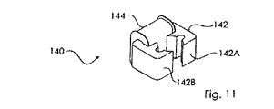
図11に示すように、固定子140は、2つの磁極片142A、142Bと、巻かれた電気的な巻き線144を有する磁性材料の固定子パック142とを備える。
As shown in FIG. 11, the
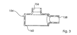
ポンプ150は、羽根車152がその内側に収容されるポンプ本体154を備える。
The
図3により明確に見ることができるように、ポンプ本体154は、送出される液体がそこを通って吸い込まれる入口すなわち吸い込み口156と、送出される液体がそこを通って排出される出口158とを含む。
As can be seen more clearly in FIG. 3, the
ポンプ本体154は、円筒要素124のカラー127に対応する寸法を有する円形開口部160も含む。これにより、ポンプ本体154を電動機本体122上に載置することによって、円形開口部160はカラー127によって閉鎖される。
The
羽根車152が内側に挿入されたとき、ポンプ本体154の内側には、吸い込み口156を出口158へ接続し、かつ吸い込み口156および出口158の寸法と等しいかまたはそれより大きい寸法を有する液体の流路162(図2を参照のこと)が画定される。このようにして、吸い込み口156を通してポンプ本体154の内側に入り込む場合がある任意の異物は、流路162を横切って、出口158から排出することができる。
When the
電動機ポンプの組み立てのためには、
固定子140を電動機本体122内に挿入し、
円筒要素124を電動機本体122内に挿入し、これによりカラー127は電動機本体122の円形開口部123を閉鎖し、
羽根車152付きの回転子132を、円筒要素124の内側に挿入し、これにより円周状の突起部136が円周状の陥凹部129の内側に挿入され、
ポンプ本体154を電動機本体122の上に載置し、これにより、ポンプ本体154の円形開口部160は円筒要素124のカラー127によって閉鎖されれば十分である。
For assembling the electric motor pump,
Insert the
The
The
It is sufficient to place the
留意されるように、電気的な巻き線144付きの固定子140は、完全に絶縁された、電動機本体122の第2の空洞130の内側に収容され、これにより、液体が入り込み、かつ電気的な巻き線144に接触する可能性がない。
As noted, the
固定子140の電気的な巻き線144に電源を供給することによって、磁極片142A、142Bにおいて磁極が発生し、これらは回転子132の磁石134の磁界と相互作用して回転子132を回転させ、したがって羽根車152を回転させる。
By supplying power to the electrical winding 144 of the
回転子132は、平坦な軸受として作用する円筒要素124の内側で回転する。円筒要素124は、高分子材料などの自己潤滑で耐摩耗な材料から作成されるのが好ましい。
The
かかる電動機の構築は、その実現のために必要な構成要素数が少ないことに起因して大変単純である。したがって、構築の時間およびコストは、相当減少する。 The construction of such a motor is very simple due to the small number of components required for its realization. Thus, the construction time and costs are significantly reduced.
回転子132は、円筒要素124の第1の空洞128に完全に組み合わせられ、これによって、回転子132と円筒要素124との間の接触表面が顕著になり、次いで回転子が円筒要素124の内側に適切に支持されることを、留意することができる。この特徴のおかげで、回転子の動作は、より整然とし、かつ摩耗は減少される。
The
さらに、以下の大変重要な特徴、すなわち円筒要素124と回転子132との間に、空間または空気室がないため、上述のいわゆるポンプ効果が生じず、したがって、前に説明したように機能不全および故障のもとである、送出される液体に含まれる不純物が円筒要素124内に入り込むのを回避することが留意されなければならない。
In addition, the following very important features, i.e., there is no space or air chamber between the
構築の単純性のおかげで、回転子と円筒要素との間の大きい接触面、および回転子を収容する空洞内に空気室がないために、電動機は、極めて信頼性が高く、かつその耐用年数は先行技術の電動機に対して相当増加する。 Thanks to the simplicity of construction, the motor is extremely reliable and has a long service life due to the large contact surface between the rotor and the cylindrical element and the absence of an air chamber in the cavity that houses the rotor. Significantly increases over prior art motors.
回転子132と円筒要素124との間の接触に起因して、固定子140と回転子132との間に存在するエアギャップが、可能な最小限まで減少し、かかる条件では固定子140の磁界および回転子132の磁界が、緊密に結合することも、考慮されるべきである。その結果、固定子140の電気的な巻き線に供給される電圧とその間を通過する電流との間の位相角φはごくわずかであり、これは0に極めて近く、その結果いわゆる力率cosφは、本質的に1に等しい。このようにして、巻線144内の電流は、可能な最小限であり、したがって、ジュール効果による電気的な損失は、最小限に減少される。このようにすることにより、電動機の効率は高く、既知の電動機と同一の電力により、より多くの電力を吸収するポンプを動作することができる。
Due to the contact between the
図12は、本発明の変形を示し、特に円筒要素224の内側に挿入された回転子232を示す。
FIG. 12 shows a variation of the present invention, in particular showing the
図13および図14により良好に示されるように、円筒要素224は円筒要素124と同様であり、すなわちカラー227を備える管状要素225を有する。管状のダクト22が管状要素225のそばに配置され、かつこれは同じ長さだがより小さい断面を有する。管状要素225の内側をダクト229の内側に接触させる、長手方向のスロット228が、管状要素225とダクト229との間の接触領域に2つの要素の全長にわたって形成される。
As better shown in FIGS. 13 and 14, the
図12、図15、および図16から見られるように、回転子232は、磁石234がその上に載置される中央ピン233を備える一方で、羽根車152がピン233の自由端233Aに載置される。ピン233は、軸方向の貫通穴237を有する。
As seen from FIGS. 12, 15 and 16, the
図12に示すように、回転子232の長さは管状要素225の長さより短く、したがって、回転子232は、管状要素225の底部226から離間される。
As shown in FIG. 12, the length of the
図12では、円筒要素224を外部で包囲する固定子240が示される。
In FIG. 12, a
ポンプが動作されるとき、回転子232は管状要素225の内側で回転し、回転子232に連結された羽根車152は、送出される液体をダクト229内へと押し、長手方向のスロット228のおかげで、液体は回転子232に接触し、回転子232と管状要素225との間の接触領域の冷却および潤滑の両方を可能にする。
When the pump is operated, the
回転子232は管状要素225の底部から離間されているため、スロット228を通る液体は、回転子232の下の領域内で管状要素225の内側へ進み、次いで回転子232の貫通穴237に沿って上がり、最終的にピン233の自由端233Aから排出される。このようにして、液体の強制的な循環が作り出され、これは長手方向のスロット228の中へ、そして回転子232と管状要素225との間の接触領域内に入る液体の量を相当に増加させる。これは、回転子と管状要素との間に摩擦がある領域を、効果的に冷却および潤滑する。
Since the
最後に、機能的にまたは概念的に同等であるいかなる変形または修正も、本発明の範囲に包含されることは明白である。 Finally, it is apparent that any variation or modification that is functionally or conceptually equivalent is included in the scope of the present invention.
例えば、異なる数の磁極片付きの、またはより多くの電気的な巻き線または異なる形状の固定子パックを有する固定子を有することが可能である。 For example, it is possible to have a stator with a different number of pole pieces or with more electrical windings or different shaped stator packs.
Claims (10)
前記電動機(120)は、さらに、前記電動機本体の外壁のうちの1つ(122A)から前記電動機本体(122)の内側に向かって延在し、これにより前記電動機本体(122)の内側を2つの空洞に分離するものである円筒要素(124、224)を有し、当該空洞は、前記回転子(132、232)を収容することができる円筒要素(124、224)の内側の第1の円筒空洞(128)と、前記固定子(140)を収容することができる前記円筒要素(124、224)の外側の第2の空洞(130)とを含むのであり、
前記円筒要素(124、224)は、第2の端部(125b)に対向する第1の開放端部(125a)を有し、前記円筒要素(124、224)は前記電動機本体(122)の外壁(122A)に位置し、これにより前記第1の円筒空洞(128)は前記円筒要素(124、224)の内側に前記回転子(132、232)を挿入するように外側に解放されるものであり、
前記電動機ポンプ(100)において、前記回転子(132、232)は少なくともその長さの一部に対して、前記円筒要素(124、224)の内部断面に本質的に対応する円形断面を有し、これにより前記回転子(132、232)は前記円筒要素(124、224)に接触し、その結果前記回転子(132、232)と前記円筒要素(124、224)との間に摩擦が生じるものであり、
前記回転子(132、232)が回転するとき、前記回転子(132、232)はシャフトレスとなり、かつ前記ポンプ(150)の羽根車(152)に軸方向に直接連結されるものであり、
前記電動機ポンプは、前記円筒要素(224)の側面上に位置付けられたダクトであって、前記円筒要素(224)と前記ダクト(229)との間の連通の長手方向のスロット(228)を画定するものである前記ダクト(229)をさらに有し、前記ダクト(229)は前記ポンプ(150)と連通し、これにより前記ポンプ(150)によって送出される流体は、前記ダクト(229)内に入り、前記回転子(232)と前記円筒要素(224)との間の接触領域を潤滑および/または冷却することが可能なものである
ことを特徴とする電動機ポンプ(100)。 An electric motor pump (100) comprising an electric motor (120) coupled to the pump (150), the electric motor (120) comprising an electric motor body (122), a stator (140), and a blade of the pump (150) A rotor (132, 232) coupled to a car (152),
The electric motor (120) further extends from one of the outer walls (122A) of the electric motor main body toward the inside of the electric motor main body (122), thereby extending the inner side of the electric motor main body (122) by two. A cylindrical element (124, 224) that is separated into two cavities, the cavity being the first inside the cylindrical element (124, 224) that can accommodate the rotor (132, 232). A cylindrical cavity (128) and a second cavity (130) outside the cylindrical element (124, 224) capable of accommodating the stator (140);
The cylindrical element (124, 224) has a first open end (125a) facing the second end (125b), and the cylindrical element (124, 224) is formed on the electric motor body (122). Located on the outer wall (122A), whereby the first cylindrical cavity (128) is released outward to insert the rotor (132, 232) inside the cylindrical element (124, 224) And
In the electric motor pump (100), the rotor (132, 232) has a circular cross section essentially corresponding to the internal cross section of the cylindrical element (124, 224) for at least part of its length. This causes the rotor (132, 232) to contact the cylindrical element (124, 224), resulting in friction between the rotor (132, 232) and the cylindrical element (124, 224). Is,
When the rotor (132, 232) rotates, the rotor (132, 232) becomes shaftless and is directly connected to the impeller (152) of the pump (150) in the axial direction;
The motor pump is a duct positioned on a side of the cylindrical element (224), defining a longitudinal slot (228) in communication between the cylindrical element (224) and the duct (229). The duct (229) is in communication with the pump (150) so that the fluid delivered by the pump (150) is contained in the duct (229). An electric motor pump (100), characterized in that it can lubricate and / or cool the contact area between the rotor (232) and the cylindrical element (224).
Applications Claiming Priority (3)
| Application Number | Priority Date | Filing Date | Title |
|---|---|---|---|
| ITVE2011A000015 | 2011-03-15 | ||
| IT000015A ITVE20110015A1 (en) | 2011-03-15 | 2011-03-15 | SYNCHRONOUS ELECTRIC MOTOR FOR THE OPERATION OF A PUMP AND ITS ELECTROPUMP. |
| PCT/IT2012/000070 WO2012123978A2 (en) | 2011-03-15 | 2012-03-13 | Synchronous electric motor for the operation of a pump and the related motor pump |
Publications (3)
| Publication Number | Publication Date |
|---|---|
| JP2014509702A JP2014509702A (en) | 2014-04-21 |
| JP2014509702A5 JP2014509702A5 (en) | 2015-04-30 |
| JP6100177B2 true JP6100177B2 (en) | 2017-03-29 |
Family
ID=43977571
Family Applications (1)
| Application Number | Title | Priority Date | Filing Date |
|---|---|---|---|
| JP2013558575A Expired - Fee Related JP6100177B2 (en) | 2011-03-15 | 2012-03-13 | Synchronous motor for the operation of pumps and related motor pumps |
Country Status (7)
| Country | Link |
|---|---|
| US (2) | US20140003977A1 (en) |
| EP (1) | EP2686558A2 (en) |
| JP (1) | JP6100177B2 (en) |
| CN (1) | CN103443467B (en) |
| CA (1) | CA2826336C (en) |
| IT (1) | ITVE20110015A1 (en) |
| WO (1) | WO2012123978A2 (en) |
Families Citing this family (7)
| Publication number | Priority date | Publication date | Assignee | Title |
|---|---|---|---|---|
| CN104747458A (en) * | 2013-12-27 | 2015-07-01 | 博西华电器(江苏)有限公司 | Liquid draining pump and household appliance with pump |
| EP3114351B1 (en) | 2014-03-06 | 2020-05-06 | Pierburg Pump Technology GmbH | Automotive electric liquid pump |
| IT201700018662A1 (en) * | 2017-02-20 | 2018-08-20 | Baruffaldi Spa | RECIRCULATION PUMP OF A THERMAL MOTOR FLUID WITH ELECTRIC MOTOR CONTROL |
| IT201800000658A1 (en) * | 2018-01-10 | 2019-07-10 | Dab Pumps Spa | PUMP ASSEMBLY WITH PERFECTED AIR GUN SLEEVE AND COUPLING BETWEEN ROTOR AND IMPROVED AIR GAP SLEEVE |
| EP3751711A4 (en) | 2018-02-08 | 2021-11-03 | LG Innotek Co., Ltd. | Motor |
| IT201800009502A1 (en) * | 2018-10-16 | 2020-04-16 | Eurosets Srl | CENTRIFUGAL PUMP WITH MAGNETIC LEVITATION |
| IT201800009506A1 (en) * | 2018-10-16 | 2020-04-16 | Eurosets Srl | CENTRIFUGAL PUMP WITH MAGNETIC LEVITATION |
Family Cites Families (21)
| Publication number | Priority date | Publication date | Assignee | Title |
|---|---|---|---|---|
| GB821609A (en) * | 1955-01-28 | 1959-10-14 | Sigmund Pumps Ltd | A pump and driving electric motor unit |
| FR69944E (en) * | 1956-06-18 | 1959-01-09 | Electric motor with free rotor for electro-pump unit | |
| DE1811430A1 (en) * | 1968-11-25 | 1970-06-11 | Gummi Jaeger Kg Gmbh & Cie | Hydraulic flow machine |
| DE1815088C3 (en) * | 1968-12-17 | 1974-11-07 | Klein, Schanzlin & Becker Ag, 6710 Frankenthal | Axial thrust compensation in canned motor pumps |
| JPS4869107U (en) * | 1971-12-03 | 1973-09-01 | ||
| FR2649450A1 (en) * | 1989-07-07 | 1991-01-11 | Rena Sa | ROTARY PUMP WITH ELECTRICAL DRIVE |
| JP3118336B2 (en) * | 1992-11-13 | 2000-12-18 | 日機装株式会社 | Canned motor pump |
| IT1259848B (en) * | 1992-11-27 | 1996-03-28 | Hydor Srl | SYNCHRONOUS ELECTRIC MOTOR, PARTICULARLY FOR IMMERSIBLE PUMPS AND INCORPORATING PUMP SUCH MOTOR |
| US6254361B1 (en) * | 1999-07-29 | 2001-07-03 | Itt Manufacturing Enterprises, Inc. | Shaftless canned rotor inline pipe pump |
| CN2477869Y (en) * | 2000-11-28 | 2002-02-20 | 金河银 | Non-axle water pump |
| JP2003269362A (en) * | 2002-03-12 | 2003-09-25 | Aisin Seiki Co Ltd | Water pump |
| JP2004092610A (en) * | 2002-09-04 | 2004-03-25 | Ee C Ii Tec Kk | Axial-flow pump of liquid-cooled system |
| JP2004293362A (en) * | 2003-03-26 | 2004-10-21 | Asmo Co Ltd | Motor pump |
| ITMI20030364U1 (en) * | 2003-07-30 | 2005-01-31 | Ind Saleri Italo Spa | ELECTRIC PUMP FOR COOLING CIRCUITS |
| US7048495B2 (en) * | 2003-11-19 | 2006-05-23 | Itt Manufacturing Enterprises, Inc. | Rotating machine having a shaft including an integral bearing surface |
| JP2005201054A (en) * | 2004-01-13 | 2005-07-28 | Koyo Seiko Co Ltd | Pump |
| ATE402343T1 (en) * | 2005-05-07 | 2008-08-15 | Grundfos Management As | PUMP UNIT |
| US7692353B2 (en) * | 2006-08-11 | 2010-04-06 | Askoll Holding S.R.L. | Permanent-magnet two-phase synchronous electric motor with mechanical start-up for washing machines and similar household appliances, in particular for washing pumps |
| CN201080915Y (en) * | 2007-06-08 | 2008-07-02 | 谭军 | Axis-free magnetic force pump |
| JP2010011591A (en) * | 2008-06-25 | 2010-01-14 | Panasonic Electric Works Co Ltd | Claw pole type motor and pump |
| CN201297259Y (en) * | 2008-12-01 | 2009-08-26 | 张良光 | High-temperature high-pressure magnetic pump |
-
2011
- 2011-03-15 IT IT000015A patent/ITVE20110015A1/en unknown
-
2012
- 2012-03-13 EP EP12720974.0A patent/EP2686558A2/en not_active Withdrawn
- 2012-03-13 JP JP2013558575A patent/JP6100177B2/en not_active Expired - Fee Related
- 2012-03-13 CN CN201280011958.XA patent/CN103443467B/en not_active Expired - Fee Related
- 2012-03-13 US US14/005,501 patent/US20140003977A1/en not_active Abandoned
- 2012-03-13 WO PCT/IT2012/000070 patent/WO2012123978A2/en active Application Filing
- 2012-03-13 CA CA2826336A patent/CA2826336C/en not_active Expired - Fee Related
-
2017
- 2017-05-22 US US15/601,108 patent/US10174761B2/en active Active
Also Published As
| Publication number | Publication date |
|---|---|
| CA2826336C (en) | 2019-03-12 |
| JP2014509702A (en) | 2014-04-21 |
| US10174761B2 (en) | 2019-01-08 |
| US20140003977A1 (en) | 2014-01-02 |
| US20170321703A1 (en) | 2017-11-09 |
| WO2012123978A2 (en) | 2012-09-20 |
| CA2826336A1 (en) | 2012-09-20 |
| WO2012123978A3 (en) | 2012-11-01 |
| CN103443467A (en) | 2013-12-11 |
| CN103443467B (en) | 2016-08-17 |
| EP2686558A2 (en) | 2014-01-22 |
| ITVE20110015A1 (en) | 2012-09-16 |
Similar Documents
| Publication | Publication Date | Title |
|---|---|---|
| JP6100177B2 (en) | Synchronous motor for the operation of pumps and related motor pumps | |
| KR101204344B1 (en) | Hot water circulating pump | |
| KR101481627B1 (en) | Water pump | |
| JP2015226465A (en) | Electric pump | |
| US20090015084A1 (en) | Rotor Cover and Electric Motor | |
| ES2785377T3 (en) | Rotor, motor, pump and cleaning device | |
| CN213540732U (en) | Electric water pump | |
| KR20090102909A (en) | Amphibious pump | |
| JP2015059434A (en) | Fuel pump | |
| KR20220070623A (en) | Electric water pump | |
| JP2019011745A (en) | Electric oil pump | |
| KR101236884B1 (en) | rising type underwater motor pump using a magnetic field | |
| JP4630123B2 (en) | Fluid pump | |
| US10995759B2 (en) | Water pump | |
| JP4939412B2 (en) | Fuel supply device | |
| JP5867723B2 (en) | Self-priming pump | |
| CN105829720A (en) | Pump device | |
| JP2014118949A (en) | Self-priming centrifugal pump | |
| JP2010540823A (en) | Fuel pump for pumping fuel from the tank to the internal combustion engine | |
| US11885346B2 (en) | Water pump | |
| KR102166718B1 (en) | Motor integrated with control unit and water pump having the same | |
| JP2004308562A (en) | Motor pump | |
| JP6357766B2 (en) | Liquid pump | |
| JP2023024031A (en) | Rotary machine | |
| JP5310520B2 (en) | Fuel pump |
Legal Events
| Date | Code | Title | Description |
|---|---|---|---|
| A521 | Request for written amendment filed |
Free format text: JAPANESE INTERMEDIATE CODE: A523 Effective date: 20150307 |
|
| A621 | Written request for application examination |
Free format text: JAPANESE INTERMEDIATE CODE: A621 Effective date: 20150307 |
|
| A977 | Report on retrieval |
Free format text: JAPANESE INTERMEDIATE CODE: A971007 Effective date: 20151215 |
|
| A131 | Notification of reasons for refusal |
Free format text: JAPANESE INTERMEDIATE CODE: A131 Effective date: 20151222 |
|
| A521 | Request for written amendment filed |
Free format text: JAPANESE INTERMEDIATE CODE: A523 Effective date: 20160208 |
|
| A131 | Notification of reasons for refusal |
Free format text: JAPANESE INTERMEDIATE CODE: A131 Effective date: 20160802 |
|
| A521 | Request for written amendment filed |
Free format text: JAPANESE INTERMEDIATE CODE: A523 Effective date: 20160929 |
|
| TRDD | Decision of grant or rejection written | ||
| A01 | Written decision to grant a patent or to grant a registration (utility model) |
Free format text: JAPANESE INTERMEDIATE CODE: A01 Effective date: 20170207 |
|
| A61 | First payment of annual fees (during grant procedure) |
Free format text: JAPANESE INTERMEDIATE CODE: A61 Effective date: 20170222 |
|
| R150 | Certificate of patent or registration of utility model |
Ref document number: 6100177 Country of ref document: JP Free format text: JAPANESE INTERMEDIATE CODE: R150 |
|
| LAPS | Cancellation because of no payment of annual fees |