JP6099755B2 - Apparatus and method for managing hyperframe number (HFN) asynchrony in radio link control (RLC) unacknowledged mode (UM) - Google Patents
Apparatus and method for managing hyperframe number (HFN) asynchrony in radio link control (RLC) unacknowledged mode (UM) Download PDFInfo
- Publication number
- JP6099755B2 JP6099755B2 JP2015536775A JP2015536775A JP6099755B2 JP 6099755 B2 JP6099755 B2 JP 6099755B2 JP 2015536775 A JP2015536775 A JP 2015536775A JP 2015536775 A JP2015536775 A JP 2015536775A JP 6099755 B2 JP6099755 B2 JP 6099755B2
- Authority
- JP
- Japan
- Prior art keywords
- transmitter
- rlc
- hfn
- receiver
- pdu
- Prior art date
- Legal status (The legal status is an assumption and is not a legal conclusion. Google has not performed a legal analysis and makes no representation as to the accuracy of the status listed.)
- Expired - Fee Related
Links
Images


Classifications
-
- H—ELECTRICITY
- H04—ELECTRIC COMMUNICATION TECHNIQUE
- H04W—WIRELESS COMMUNICATION NETWORKS
- H04W56/00—Synchronisation arrangements
- H04W56/001—Synchronization between nodes
-
- H—ELECTRICITY
- H04—ELECTRIC COMMUNICATION TECHNIQUE
- H04L—TRANSMISSION OF DIGITAL INFORMATION, e.g. TELEGRAPHIC COMMUNICATION
- H04L1/00—Arrangements for detecting or preventing errors in the information received
- H04L1/12—Arrangements for detecting or preventing errors in the information received by using return channel
- H04L1/16—Arrangements for detecting or preventing errors in the information received by using return channel in which the return channel carries supervisory signals, e.g. repetition request signals
- H04L1/18—Automatic repetition systems, e.g. Van Duuren systems
- H04L1/1867—Arrangements specially adapted for the transmitter end
- H04L1/1896—ARQ related signaling
-
- H—ELECTRICITY
- H04—ELECTRIC COMMUNICATION TECHNIQUE
- H04W—WIRELESS COMMUNICATION NETWORKS
- H04W56/00—Synchronisation arrangements
- H04W56/001—Synchronization between nodes
- H04W56/002—Mutual synchronization
Description
米国特許法第119条に基づく優先権の主張
本特許出願は、いずれも本出願の譲受人に譲渡され、参照により本明細書に明確に組み込まれる、2012年10月10日に出願された米国仮出願番号第61/712,120号、および2013年9月11日に出願された非仮出願番号第14/024,156号の優先権を主張する。
Priority claim under 35 USC 119 This patent application is a U.S. application filed on 10 October 2012, both assigned to the assignee of this application and expressly incorporated herein by reference. Claims priority of provisional application number 61 / 712,120 and non-provisional application number 14 / 024,156 filed on September 11, 2013.
本開示の態様は、一般に、ワイヤレス通信システムに関し、より詳細には、無線リンク制御(RLC:radio link control)非確認応答モード(UM:unacknowledged mode)でのハイパーフレーム番号(HFN)非同期を管理することに関する。 Aspects of the present disclosure generally relate to wireless communication systems, and more particularly, manage hyperframe number (HFN) asynchronization in radio link control (RLC) unacknowledged mode (UM). About that.
電話、ビデオ、データ、メッセージング、放送などの様々な通信サービスを提供するために、ワイヤレス通信ネットワークが広範囲に展開されている。そのようなネットワークは、たいていは多元接続ネットワークであり、利用可能なネットワークリソースを共有することによって、複数のユーザ向けの通信をサポートする。そのようなネットワークの一例は、UMTS Terrestrial Radio Access Network(UTRAN)である。UTRANは、第3世代パートナーシッププロジェクト(3GPP)によってサポートされる第3世代(3G)モバイルフォン技術である、Universal Mobile Telecommunications System(UMTS)の一部として定義される無線アクセスネットワーク(RAN)である。UMTSは、Global System for Mobile Communications(GSM(登録商標))技術の後継であり、広帯域符号分割多元接続(W-CDMA)、時分割符号分割多元接続(TD-CDMA)、および時分割同期符号分割多元接続(TD-SCDMA)などの様々なエアインターフェース規格を現在サポートしている。UMTSは、関連するUMTSネットワークのデータ転送の速度および容量を向上させる、High Speed Packet Access(HSPA)のような改良型の3Gデータ通信プロトコルもサポートする。 Wireless communication networks are widely deployed to provide various communication services such as telephone, video, data, messaging, broadcast, and so on. Such networks are often multi-access networks and support communication for multiple users by sharing available network resources. An example of such a network is the UMTS Terrestrial Radio Access Network (UTRAN). UTRAN is a radio access network (RAN) defined as part of the Universal Mobile Telecommunications System (UMTS), a third generation (3G) mobile phone technology supported by the Third Generation Partnership Project (3GPP). UMTS is the successor to Global System for Mobile Communications (GSM) technology, wideband code division multiple access (W-CDMA), time division code division multiple access (TD-CDMA), and time division synchronous code division. Various air interface standards such as multiple access (TD-SCDMA) are currently supported. UMTS also supports advanced 3G data communication protocols such as High Speed Packet Access (HSPA) that improve the speed and capacity of data transfer in the associated UMTS network.
W-CDMAでは、RLC非確認応答モード(UM)は、受信されたプロトコルデータユニット(PDU)の成功または失敗が確認応答されない無線リンクプロトコルである。RLC UMは、リアルタイムアプリケーションまたは準リアルタイムアプリケーションならびに遅延敏感アプリケーションのために使用され得る。RLC UMでは、短シーケンス番号(SN:sequence number)と長SNとの組合せである、カウント-Cと呼ばれる時間変動パラメータ値またはカウントを利用することによって送信パケットに対して暗号化および解読が実行され得る。短SNは、RLC UMプロトコルデータユニット(PDU)ヘッダの一部である7ビットRLC SNである。長SNは、RLC SNサイクルごとに増分される25ビットRLC UM HFNである。したがって、127個の連続するRLC UM PDUを送信するごとに、送信RLC UMエンティティにおけるRLC SNサイクルが完了し、送信RLC UMエンティティにおけるRLC SNがラップアラウンドし、送信RLC UMエンティティにおけるHFNが増分される。一方、受信RLC UMエンティティが逃したPDUに気づかず、受信RLC UMエンティティが127個以上の連続するPDUを逃す場合、受信RLC UMエンティティにおけるHFNが増分されず、送信および受信RLC UMエンティティにおけるHFN間の非同期を生じる。その後、さらなるRLC UM PDUが正しく送信および受信される場合、送信および受信RLC UMエンティティにおけるHFN間の非同期により、受信RLC UM PDU中のデータが受信RLC UMエンティティにおいて間違って解読されることになり、送信および受信RLC UMエンティティはそのような誤りを検出することが可能でないので、破損したPDUが上位レイヤにただ転送されることになる。したがって、RLC UMでは、HFN非同期は、たとえば、ボイスオーバーHSPAアプリケーションにおいて不正確なサービスデータユニット(SDU)生成または聞き取りにくい音声を生じ得る。 In W-CDMA, RLC unacknowledged mode (UM) is a radio link protocol in which the success or failure of a received protocol data unit (PDU) is not acknowledged. RLC UM can be used for real-time or near real-time applications as well as delay sensitive applications. In RLC UM, transmission packets are encrypted and decrypted by using a time-variable parameter value or count called count-C, which is a combination of short sequence number (SN) and long SN. obtain. The short SN is a 7-bit RLC SN that is part of the RLC UM protocol data unit (PDU) header. The long SN is a 25-bit RLC UM HFN that is incremented every RLC SN cycle. Thus, for every 127 consecutive RLC UM PDUs transmitted, the RLC SN cycle at the transmitting RLC UM entity is completed, the RLC SN at the transmitting RLC UM entity wraps around, and the HFN at the transmitting RLC UM entity is incremented. . On the other hand, if the receiving RLC UM entity is unaware of the missed PDU and the receiving RLC UM entity misses 127 or more consecutive PDUs, the HFN in the receiving RLC UM entity is not incremented, and the HFN between the transmitting and receiving RLC UM entities Asynchronous results. Later, if further RLC UM PDUs are correctly transmitted and received, the asynchronousness between the HFNs at the transmitting and receiving RLC UM entities will cause the data in the received RLC UM PDUs to be incorrectly decoded at the receiving RLC UM entity, Since the sending and receiving RLC UM entities are not capable of detecting such errors, the corrupted PDU will simply be forwarded to higher layers. Thus, in RLC UM, HFN asynchrony can result in inaccurate service data unit (SDU) generation or voice that is difficult to hear in, for example, voice over HSPA applications.
モバイルブロードバンドアクセスに対する要望が増え続けるにつれて、研究開発は、モバイルブロードバンドアクセスに対する高まる要望を満たすためだけでなく、モバイル通信によるユーザ経験を進化させ拡張させるためにも、UMTS技術を進化させ続けている。したがって、この場合、RLC UMでのHFN非同期を管理するための改善された装置および方法が望まれる。 As the demand for mobile broadband access continues to increase, R & D continues to evolve UMTS technology not only to meet the growing demand for mobile broadband access, but also to evolve and expand the user experience with mobile communications. Therefore, in this case, an improved apparatus and method for managing HFN asynchrony in RLC UM is desired.
以下で、1つまたは複数の態様の基本的理解を与えるために、そのような態様の簡略化された概要を提示する。この概要は、すべての企図された態様の包括的な概観ではなく、すべての態様の主要または重要な要素を特定するものでも、いずれかまたはすべての態様の範囲を定めるものでもない。その唯一の目的は、後で提示するより詳細な説明の導入として、1つまたは複数の態様のいくつかの概念を簡略化された形で提示することである。 The following presents a simplified summary of such aspects in order to provide a basic understanding of one or more aspects. This summary is not an extensive overview of all contemplated aspects and does not identify key or critical elements of all aspects or delineate the scope of any or all aspects. Its sole purpose is to present some concepts of one or more aspects in a simplified form as a prelude to the more detailed description that is presented later.
本開示の態様は、一般に、ワイヤレス通信システムに関し、より詳細には、RLC UMでのHFN非同期を管理するための装置および方法に関する。 Aspects of the present disclosure relate generally to wireless communication systems, and more particularly to an apparatus and method for managing HFN asynchrony in RLC UM.
一態様では、送信機によって、HFN非同期条件を判断するステップであって、複数の連続するPDUのうちの少なくとも1つのPDUが受信機に送信機によって正常に送信されたとき、HFN非同期条件が偽となり、複数の連続するPDUのすべてが失われたとき、HFN非同期条件が真となる、判断するステップと、HFN非同期条件が真であるとき、送信機によって送信機の送信機HFNを調整するステップであって、調整された送信機HFNが送信されるべき新しいPDUのために使用される、調整するステップとを含む、RLC UMでの送信機と受信機との間のデータ通信の方法を提供する。 In one aspect, the step of determining an HFN asynchronous condition by a transmitter, wherein the HFN asynchronous condition is false when at least one PDU of a plurality of consecutive PDUs is successfully transmitted to the receiver by the transmitter. And determining that the HFN asynchronous condition is true when all of the multiple consecutive PDUs are lost and adjusting the transmitter HFN of the transmitter by the transmitter when the HFN asynchronous condition is true. Providing a method of data communication between a transmitter and a receiver in the RLC UM, including a step of adjusting, wherein the adjusted transmitter HFN is used for a new PDU to be transmitted To do.
一態様では、送信機によって、HFN非同期条件を判断するためのコードであって、複数の連続するPDUのうちの少なくとも1つのPDUが受信機に送信機によって正常に送信されたとき、HFN非同期条件が偽となり、複数の連続するPDUのすべてが失われたとき、HFN非同期条件が真となる、判断するためのコードと、HFN非同期条件が真であるとき、送信機によって送信機の送信機HFNを調整するためのコードであって、調整された送信機HFNが送信されるべき新しいPDUのために使用される、調整するためのコードとを含む、コンピュータ可読媒体を含む、RLC UMでの送信機と受信機との間のデータ通信のためのコンピュータプログラム製品を提供する。 In one aspect, a code for determining an HFN asynchronous condition by a transmitter when at least one PDU of a plurality of consecutive PDUs is successfully transmitted to the receiver by the transmitter. Is false, and when all consecutive PDUs are lost, the code to determine that the HFN asynchronous condition is true, and the transmitter transmitter HFN by the transmitter when the HFN asynchronous condition is true Transmission on the RLC UM, including a computer readable medium, including a code for adjusting, wherein the adjusted transmitter HFN is used for a new PDU to be transmitted A computer program product for data communication between a receiver and a receiver is provided.
一態様では、送信機によって、HFN非同期条件を判断するための手段であって、複数の連続するPDUのうちの少なくとも1つのPDUが受信機に送信機によって正常に送信されたとき、HFN非同期条件が偽となり、複数の連続するPDUのすべてが失われたとき、HFN非同期条件が真となる、判断するための手段と、HFN非同期条件が真であるとき、送信機によって送信機の送信機HFNを調整するための手段であって、調整された送信機HFNが送信されるべき新しいPDUのために使用される、調整するための手段とを含む、RLC UMでの送信機と受信機との間のデータ通信のための装置を提供する。 In one aspect, means for determining an HFN asynchronous condition by a transmitter when an at least one PDU of a plurality of consecutive PDUs is successfully transmitted by a transmitter to a receiver. Means to determine that the HFN asynchronous condition is true when all of the multiple consecutive PDUs are lost, and the transmitter transmitter HFN by the transmitter when the HFN asynchronous condition is true Between the transmitter and receiver in the RLC UM, including means for adjusting, wherein the adjusted transmitter HFN is used for new PDUs to be transmitted. Provide a device for data communication between.
一態様では、少なくとも1つのプロセッサと、少なくとも1つのプロセッサに結合されたメモリとを含み、少なくとも1つのプロセッサが、送信機によって、HFN非同期条件を判断することであって、複数の連続するPDUのうちの少なくとも1つのPDUが受信機に送信機によって正常に送信されたとき、HFN非同期条件が偽となり、複数の連続するPDUのすべてが失われたとき、HFN非同期条件が真となる、判断することと、HFN非同期条件が真であるとき、送信機によって送信機の送信機HFNを調整することであって、調整された送信機HFNが送信されるべき新しいPDUのために使用される、調整することとを行うように構成された、RLC UMでの送信機と受信機との間のデータ通信のための装置を提供する。 In one aspect, comprising at least one processor and a memory coupled to the at least one processor, the at least one processor determining by the transmitter an HFN asynchronous condition, wherein the plurality of consecutive PDUs Determine that when at least one of the PDUs is successfully transmitted by the transmitter to the receiver, the HFN asynchronous condition is false, and when all consecutive PDUs are lost, the HFN asynchronous condition is true And adjusting the transmitter HFN of the transmitter by the transmitter when the HFN asynchronous condition is true, the adjusted transmitter HFN being used for new PDUs to be transmitted An apparatus for data communication between a transmitter and a receiver in an RLC UM configured to perform the above is provided.
本開示のこれらの態様および他の態様は、以下の発明を実施するための形態を概観することによってより完全に理解されるだろう。 These and other aspects of the disclosure will be more fully understood by reviewing the following detailed description.
開示される態様を限定するためではなく例示するために提供される添付の図面とともに、開示される態様が以下に記載され、同様の記号表示は同様の要素を示している。 The disclosed aspects are described below with reference to the accompanying drawings, which are provided to illustrate, but not limit, the disclosed aspects, with like designations indicating like elements.
添付の図面に関する下記の詳細な説明は、様々な構成の説明として意図されており、本明細書で説明される概念が実行され得る唯一の構成を表すように意図されているわけではない。詳細な説明は、様々な概念の完全な理解をもたらす目的で、具体的な詳細を含んでいる。しかし、これらの概念がこれらの具体的な詳細なしに実行され得ることが、当業者には明らかであろう。場合によっては、そのような概念を曖昧にするのを回避する目的で、周知の構造および構成要素がブロック図の形式で示されている。 The following detailed description of the accompanying drawings is intended as a description of various configurations and is not intended to represent the only configurations in which the concepts described herein can be practiced. The detailed description includes specific details for the purpose of providing a thorough understanding of various concepts. However, it will be apparent to those skilled in the art that these concepts may be practiced without these specific details. In some instances, well-known structures and components are shown in block diagram form in order to avoid obscuring such concepts.
本開示のいくつかの態様によれば、RLC UMでのHFN非同期を検出し補正する方法および装置を提供する。RLC UMで受信機と通信している送信機は、HFN非同期の条件を判断し得、HFN非同期が存在する場合、送信機は、暗号化パラメータが受信機と同期することを保証するために送信機HFNを更新または調整し得る。したがって、RLC UMでのHFN非同期検出ならびに拡張HFN更新および同期を用いて、送信機は、正しいSDUが受信機において受信されたRLC UM PDUの中から解読され得るように、送信機HFNが受信機HFNと同じであることを保証することができる。一態様では、これにより、パケット呼中の間違ったSDU(インターネットプロトコル(IP)フレーム)による通話途切れが低減し得、また、HSPAチャネルを介してRLC UMエンティティが使用されるか、またはHSPAチャネルを介してボイスオーバーIP(VoIP)が使用されるとき回路交換(CS)呼中の聞き取りにくい音声を回避することになり得る。本明細書をHSPA無線技術に関して主に提示するが、本明細書は、他の無線技術(たとえば、ロングタームエボリューション(LTE))がRLC UMにあるとき、それらの他の技術にも適用され得る。 According to some aspects of the present disclosure, a method and apparatus for detecting and correcting HFN asynchrony in RLC UM is provided. A transmitter communicating with a receiver with RLC UM can determine the condition of the HFN asynchronous, and if HFN asynchronous is present, the transmitter transmits to ensure that the encryption parameters are synchronized with the receiver. The machine HFN can be updated or adjusted. Thus, using HFN asynchronous detection in RLC UM and extended HFN update and synchronization, the transmitter can ensure that the transmitter HFN receives the receiver so that the correct SDU can be decoded from among the RLC UM PDUs received at the receiver. Can be guaranteed to be the same as HFN. In one aspect, this may reduce call interruptions due to incorrect SDU (Internet Protocol (IP) frames) in packet calls, and RLC UM entities may be used over HSPA channels or When voice over IP (VoIP) is used, it may be possible to avoid unintelligible voice during circuit switched (CS) calls. Although this specification is primarily presented with respect to HSPA radio technology, this specification may also apply to other technologies when other radio technologies (e.g., Long Term Evolution (LTE)) are in RLC UM. .
図1を参照すると、一態様では、システム1000は、第2の通信装置1004と通信している第1の通信装置1002を含む。第1の通信装置1002と第2の通信装置1004とは、RLC UMで両方とも動作し、それぞれ、送信RLC UMエンティティ1006および受信RLC UMエンティティ1018を含む。RLC UMでの動作に従って、送信RLC UMエンティティ1006は、受信RLC UMエンティティ1018にパケットを送信し、送信機RLC UM SN 1010と送信機HFN 1012とを利用することによって送信パケットに対して暗号化を実行する。相応して、RLC UMでの動作に従って、受信RLC UMエンティティ1018は、受信機RLC UM SN 1024と受信機HFN 1020とを利用することによって受信パケットを解読する。したがって、受信RLC UMエンティティ1018において受信パケットの解読に成功するために、受信機RLC UM SN 1024は、受信パケット中のRLC UM PDUヘッダの一部である送信機RLC UM SN 1010に基づいて判断されるが、受信機HFN 1020は、送信機HFN 1012に関する明示的情報なしに送信機HFN 1012と同期されなければならない。
Referring to FIG. 1, in one aspect,
いくつかの態様では、送信RLC UMエンティティ1006において、利用可能なRLC SN数の総数に対応する複数の連続するRLC UM PDUを送信すると、RLC SNサイクルが完了し、送信機RLC UM SN 1010がラップアラウンドし、送信機HFN 1012が増分される。たとえば、HSPA使用事例の一態様では、利用可能なRLC SN数の総数に対応する複数の連続するRLC UM PDUは、127個の連続するRLC UM PDUである。一方、受信RLC UMエンティティ1018が、利用可能なRLC SN数の総数よりも多く、たとえば、HSPAの例において127個以上の連続するPDUよりも多く逃す場合、受信RLC UMエンティティ1018は、逃した連続するPDUに気づかないので、受信機HFN 1020は増分されず、送信機HFN 1012と受信機HFN 1020との間の非同期を生じる。その後、さらなるRLC UM PDUが正しく送信および受信される場合、送信機HFN 1012と受信機HFN 1020との間の非同期により、受信されたRLC UM PDU中のデータが受信RLC UMエンティティ1018において間違って解読されることになる。
In some aspects, when the transmitting
RLC UMでの送信側と受信側との間の通信は非確認応答動作であるが、3GPP規格は、送信パケットの成功または失敗について知るために送信RLC UMエンティティ1006内にレイヤ間通信の機構を与えている。たとえば、25.321 MAC仕様では、プリミティブを使用することによってPDU送信ごとのステータスを示すための規定がある。プリミティブは、順序またはデータ形式を有し、上位レイヤと下位レイヤとの間の送信または受信情報を交換するために使用される。Table 1(表1)に、MACレイヤとRLCレイヤとの間のプリミティブの1つの非限定的な構成を示すが、他の構成も可能であり得る。
While communication between the sender and receiver in RLC UM is an unacknowledged operation, the 3GPP standard provides a mechanism for inter-layer communication within the sending

Table 1(表1)に示すように、各論理チャネルおよびトランスポートチャネルは、MACサブレイヤとRLCサブレイヤとの間でMAC_DATAプリミティブとMAC_STATUSプリミティブとを交換し得る。Table 1(表1)のパラメータヘッダの下に示すように、プリミティブは、上位レイヤと下位レイヤとの間に要求、指示、応答、確認などを与え得る。たとえば、MACトランスポートフォーマット組合せ(TFC:transport format combination)選択プロセスが実行された後、選択された論理チャネルの現在のバッファ中のデータが送信されるように要求されるとき、MAC_DATA_INDプリミティブが使用され得る。論理チャネルは、要求に従ってMAC_DATA_REQプリミティブを使用してトランスポートチャネルにPDUを送信し得る。MAC_STATUS_INDプリミティブは、トランスポートチャネルが論理チャネル中で送信可能なPDUのサイズおよび数を各論理チャネルに通知するように使用され得る。 As shown in Table 1, each logical channel and transport channel may exchange MAC_DATA and MAC_STATUS primitives between the MAC sublayer and the RLC sublayer. As shown below the parameter header in Table 1, the primitive may provide a request, indication, response, confirmation, etc. between the upper and lower layers. For example, the MAC_DATA_IND primitive is used when the data in the current buffer for the selected logical channel is required to be transmitted after the MAC transport format combination (TFC) selection process has been performed. obtain. The logical channel may send PDUs to the transport channel using the MAC_DATA_REQ primitive according to the request. The MAC_STATUS_IND primitive can be used to inform each logical channel of the size and number of PDUs that the transport channel can transmit in the logical channel.
いくつかの態様によれば、送信(TX)ステータスプリミティブは、RLCサブレイヤにPDU送信ごとのステータスを示すためにMACサブレイヤによって使用され得る。たとえば、TXステータスは、前の送信時間間隔(TTI)においてRLC PDUの送信が失敗したことをRLCに示すために、「送信不成功」の値に設定され得る。TXステータスはまた、要求されたRLC PDUが物理レイヤによる送信のためにサブミットされたことをRLCに示すために、「送信成功」の値に設定され得る。いくつかの態様では、PDUの送信ステータスは、MACサブレイヤとは異なるプロトコルサブレイヤから取得され得る。 According to some aspects, a transmission (TX) status primitive may be used by the MAC sublayer to indicate status per PDU transmission to the RLC sublayer. For example, the TX status may be set to a “transmission unsuccessful” value to indicate to the RLC that the transmission of the RLC PDU failed in the previous transmission time interval (TTI). The TX status may also be set to a “transmission successful” value to indicate to the RLC that the requested RLC PDU has been submitted for transmission by the physical layer. In some aspects, the transmission status of the PDU may be obtained from a protocol sublayer that is different from the MAC sublayer.
概して、いくつかの態様では、無線ベアラがRLC UMを使用しているとき、暗号化は、RLCサブレイヤ中で実行され得る。これらの態様では、暗号化誤りは、32ビット暗号化パラメータである暗号化シーケンス番号カウント-Cに関係し得る。RLC UMを使用して、アップリンク無線ベアラごとに1つのカウント-C値があり、ダウンリンク無線ベアラごとに1つのカウント-C値がある。Table 2(表2)に、RLC UMでのカウント-C構成を示す。 In general, in some aspects, encryption may be performed in the RLC sublayer when the radio bearer is using RLC UM. In these aspects, the encryption error may relate to encryption sequence number count-C, which is a 32-bit encryption parameter. Using RLC UM, there is one count-C value per uplink radio bearer and one count-C value per downlink radio bearer. Table 2 shows the count-C configuration in RLC UM.
Table 2(表2)に示すように、RLC UMでのカウント-Cは、「短」シーケンス番号と「長」シーケンス番号との2つの部分から構成される。「短」シーケンス番号は、カウント-Cの最下位ビットを形成し、RLC UM PDUヘッダの一部である7ビットRLC UM SNである。「長」シーケンス番号は、カウント-Cの最上位ビットを形成し、RLC SNサイクルごとに増分される25ビットRLC UM HFNである。HFNは、パラメータSTARTによって初期化され得、たとえば、ワイヤレス送信/受信ユニット(WTRU:wireless transmit/receive unit)および無線ネットワークコントローラ(RNC:radio network controller)は、RLC UM HFNの20の最上位ビットをSTARTに初期化し得、RLC UM HFNの残りのビットは、0に初期化され得る。HFNは、パケットとともに明示的に送信されないことがある。 As shown in Table 2, the count-C in RLC UM is composed of two parts, a “short” sequence number and a “long” sequence number. The “short” sequence number is a 7-bit RLC UM SN that forms the least significant bit of Count-C and is part of the RLC UM PDU header. The “long” sequence number is a 25-bit RLC UM HFN that forms the most significant bits of Count-C and is incremented every RLC SN cycle. The HFN can be initialized with the parameter START, e.g. the wireless transmit / receive unit (WTRU) and the radio network controller (RNC) have the 20 most significant bits of the RLC UM HFN. It can be initialized to START and the remaining bits of RLC UM HFN can be initialized to 0. The HFN may not be sent explicitly with the packet.
さらに、一態様では、送信RLC UMエンティティ1006は、MACサブレイヤの機能を実行するMACエンティティ1014をさらに含む。TTIごとに、MACエンティティ1014は、ハイブリッド自動再送要求(HARQ)エンティティ1016によって受信された現在のHARQの様々なファクタ(バッファ占有、優先度、利用可能な電力、利用可能な許可など)に基づいて、複数のPDUを各論理チャネルから送信するように要求し得る。MACエンティティ1014は、HARQエンティティ1016によって受信されたピアフィードバック(ACK/NAK)に基づいてHARQエンティティ1016の送信ステータスについての知識を有し得る。いくつかの態様では、送信RLC UMエンティティ1006は、HARQエンティティ1016の送信ステータスに基づいてMACエンティティ1014から各PDUの成功/不成功送信ステータスを取得し得る。したがって、送信RLC UMエンティティ1006は、PDU送信ステータスの履歴1008を記憶し得、複数の連続するPDUが失われたこと、たとえば、128個の連続するPDUが失われたことをPDU送信ステータスの履歴1008が示すときはいつでもHFN非同期条件1022を真に設定するHFN非同期条件判断構成要素1024を含み得る。HFN非同期条件1022は、そのような複数のPDUのうちの少なくとも1つのPDUが正常に送信されたこと、たとえば、最後の128個のPDUのうちの少なくとも1つのPDUが正常に送信されたことをPDU送信ステータスの履歴1008が示すときはいつでも偽に設定され得る。いくつかの態様では、たとえば、HFN非同期条件判断構成要素1024は、HARQエンティティ1016の送信ステータスに基づいて各PDUの成功/不成功送信ステータスを判断する送信ステータス判断構成要素1028を含み得る。
Further, in an aspect, the transmitting
いくつかの態様では、送信RLC UMエンティティ1006および/またはHFN非同期条件判断構成要素1024は、真のHFN非同期条件1022を生じたHFN非同期の値を判断し得る。HFN非同期の値を判断するために、MACエンティティ1014と送信RLC UMエンティティ1006との間のレイヤ間通信が使用され得る。たとえば、MACエンティティ1014は、HARQ送信ごとにHARQ演算結果を与え得、第1の通信装置1002内のレイヤ間通信インターフェースを介して送信機RLC UMエンティティ1006に「失敗/成功」フィードバックをも与え得る。送信RLC UMエンティティ1006は、次いで、対応する送信機RLC UM SN 1010を用いて各HARQ失敗/成功のマッピングを追跡し得る。たとえば、一態様では、HFN非同期条件判断構成要素1024は、対応する送信機RLC UM SN 1010を用いて各HARQ失敗/成功のマッピングを追跡する送信ステータスマッピング構成要素1030を含み得る。一例によれば、送信RLC UMエンティティ1006、HFN非同期条件判断構成要素1024、および/または送信ステータスマッピング構成要素1030は、各MAC HARQ(再)送信結果(たとえば、失敗/成功)に基づいて、少なくとも直近の128個のRLC UM PDU SNに関係する失敗/成功を記録するビットマップのアレイを維持し得る。いくつかの態様では、送信RLC UMエンティティ1006、HFN非同期条件判断構成要素1024、および/または送信ステータスマッピング構成要素1030は、RLC PDUサイズが「固定サイズ」になるように構成されたか、「フレキシブルなサイズ」になるように構成されたかにかかわらず、このマッピングを追跡し得る。これらの態様では、RLC PDUサイズ構成を仮定して、2つのレイヤ(たとえば、MACおよびRLC)間のPDUマッピングが固定とフレキシブルの両方のRLC PDUサイズに対して行われ得る。いくつかの態様では、論理チャネルと物理チャネル(たとえば、オーバージエア無線チャネル)との間のマッピングがネットワークによって構成され得る場合、送信機RLC UMエンティティ1006、HFN非同期条件判断構成要素1024、および/または送信ステータスマッピング構成要素1030は、追加または代替として、オーバージエア送信のために論理チャネルがどのように多重化されるかにかかわらず、PDUマッピングを追跡し得る。
In some aspects, the transmitting
いくつかの態様では、第1の通信装置1002は、基地局またはノードBなどのネットワークエンティティであり得る第2の通信装置1004にアップリンクパケットを送信するUEまたはモバイルデバイスであり得る。これらの態様では、MACおよびRLCはモバイルデバイス中にコロケートされるので、レイヤ間通信/シグナリングは、本明細書で説明するTXステータスプリミティブなどのプリミティブの実装を通して行われ得る。
In some aspects, the
いくつかの態様では、第1の通信装置1002は、UEまたはモバイルデバイスであり得る第2の通信装置1004にダウンリンクパケットを送信するネットワークエンティティであり得る。これらの態様では、MACレイヤとRLCレイヤとの間のレイヤ間通信は、ノードB(MACエンティティ1014とHARQエンティティ1016とが位置する場所)とRNC(送信RLC UMエンティティ1006が位置する場所)との間のインターフェースまたはシグナリングを介するものであり得る。このインターフェースまたはシグナリングは、既存のIuインターフェースの強化(たとえば、コアネットワークにRNCを接続する外部インターフェース)であり得る。このインターフェースまたはシグナリングは、RNC中の送信RLC UMエンティティ1006が、本明細書で説明するように、HFN非同期条件1022を判断することができるように、ノードBからRNCにMAC/HARQ「失敗/成功」フィードバックを与え得る。
In some aspects, the
いくつかの態様では、HFN非同期条件1022が真であると判断されたとき、送信機HFN 1012は、送信機HFN 1012が受信機HFN 1020と同期し、送信RLC UMエンティティ1006と受信RLC UMエンティティ1018とが暗号化/解読のためにカウント-C中の同じHFNを使用するように、送信RLC UMエンティティ1006および/またはHFN調整構成要素1026によって調整、たとえば、減分され得る。
In some aspects, when the HFN
以下は、送信RLC UMエンティティ1006および/またはHFN調整構成要素1026によって送信機HFN 1012がどのように調整され得るかについて示す一例である。送信機HFN 1012と受信機HFN 1020はどちらも1に等しく、送信RLC UMエンティティ1006および受信RLC UMエンティティ1018が、RLC PDU SN0〜25に正常に交換すると仮定する。また、送信RLC UMエンティティ1006の後にHFN 1を使用したRLC UM PDU SN 26〜127の送信が続き、そのとき、送信機RLC UM SN 1010が0にロールオーバすると仮定し、さらに、RLC UM PDU SN 26〜127が送信に失敗する(102個の失敗したPDU)、たとえば、これらの送信について否定応答(NACK)がHARQエンティティ1016によって受信されると仮定する。このNACK情報は、HARQエンティティ1016においてHARQ ACK/NACKステータスに基づいて抽出され得、MACエンティティ1014から送信RLC UMエンティティ1006に送信され得る。送信機RLC UM SN 1010が0で再開する(またはロールオーバする)とき、送信機HFN 1012は2に増分される。ここで、この再開されたRLC UM SN 1010で、別のRLC UM PDU SN0〜25がHFN 2を使用して送信されるが、送信に失敗する(26個の失敗したPDU)と仮定する。したがって、合計128個の連続するPDUの送信に失敗した。この状況では、HFN非同期の検出がない場合、送信RLC UMエンティティ1006はHFN 2を使用するが、受信RLC UMエンティティ1018はHFN 1を使用し、HFN非同期が生じ、ボイスオーバーHSPAアプリケーションの場合音声が聞き取りにくくなる。しかしながら、128個の連続するPDUの送信に失敗したという指示に基づいてHFN非同期が真として検出された場合、送信機HFN 1012が調整(たとえば、減分)され得、送信されるべき新しいPDUのためにHFN 1が使用され得る。一方、受信RLC UMエンティティ1018において、最後の128個のRLC UM PDUのいずれも受信されず、受信機RLC UM SN 1024がロールオーバしなかったので、受信機HFN 1020は1に等しいままである。したがって、送信機と受信機の両方が同じHFN 1を使用しており、カウント-Cパラメータが同じであり、その結果、暗号化/解読パラメータの同期が保証される。
The following is an example illustrating how the
ある態様では、HFN非同期条件1022を判断するために使用される複数の連続するPDUのサイズ(たとえば、複数のPDU内のPDUの数)は、1つの全RLC SNサイクル以上になり得る。一態様では、たとえば、HFN非同期条件1022を判断するために使用される複数の連続するPDUのサイズは、1つの全RLC SNサイクルの倍数になり得る。この態様では、送信機HFN 1012は、1つの全RLC SNサイクルの倍数に従って調整され得る。たとえば、1つの全RLC SNサイクルの倍数が3つの全RLC SNサイクルである場合、真のHFN非同期条件1022の判断時に、送信機HFN 1012は、HFNを再同期するために送信RLC UMエンティティ1006において3だけ減算され得る。一例によれば、1つの全RLC SNサイクルの長さは128である。
In an aspect, the size of multiple consecutive PDUs used to determine the HFN asynchronous condition 1022 (eg, the number of PDUs in the multiple PDUs) may be one full RLC SN cycle or more. In one aspect, for example, the size of multiple consecutive PDUs used to determine the HFN
図2を参照すると、一態様では、RLC UMでのHFN非同期を管理するための方法2000が示されている。方法2000の1つまたは複数の態様によれば、送信機は、HFN非同期を検出し、送信機がRLC UMで動作しているときでも修正アクションを取り得る。説明のため、上記の図1を参照して方法2000について説明する。他の実装形態では、図2の方法2000を実施する際に、図1に示した構成要素とは異なる構成要素を含む他のシステムおよび/あるいは通信装置、UE、ノードB、または他の装置が使用され得ることを理解されたい。
Referring to FIG. 2, in one aspect, a
ブロック2002において、方法2000は、複数の連続するPDUのうちの少なくとも1つのPDUが正常に送信されたとき偽となり、複数の連続するPDUのすべてが失われたとき真となるHFN非同期条件を判断するステップを含む。たとえば、一態様では、第1の通信装置1002および/またはHFN非同期条件判断構成要素1024は、HARQエンティティ1016から取得されたPDU送信ステータスの履歴1008に基づいてHFN非同期条件1022を判断し得る。HFN非同期条件1022は、複数の連続するPDU(たとえば、128個の連続するPDU)のすべてが失われたとき真に設定され得、複数の連続するPDUのうちの少なくとも1つのPDUが正常に送信されたとき偽に設定され得る。いくつかの態様によれば、TXステータスプリミティブは、RLCサブレイヤにPDU送信ごとのステータスを示すためにMACサブレイヤによって使用され得る。
At
たとえば、ブロック2002の実行の一態様では、TTIごとに、MACエンティティは、現在のHARQの様々なファクタ(たとえば、バッファ占有、優先度、利用可能な電力、利用可能な許可など)に基づいて、複数のPDUを各論理チャネルから送信するように要求し得る。いくつかの態様では、MACエンティティはまた、ピアフィードバック(たとえば、ACK/NAK)に基づいてHARQエンティティ送信ステータスを知り得る。いくつかの態様では、たとえば、RLCエンティティは、MACエンティティからのHARQステータスに基づいて各PDUの成功/不成功送信ステータスを入手し得る。したがって、これらの態様では、複数の連続するPDU(たとえば、128個の連続するPDU)の損失が送信機によって識別されたとき、HFN非同期は真に設定され得る。また、最後の複数の連続するPDU(たとえば、最後の128個の連続するPDU)のうちの少なくとも1つのPDUが正常に送信されたと識別されたとき、HFN非同期は偽に設定され得る。
For example, in one aspect of the execution of
いくつかの態様では、MACサブレイヤがRLCサブレイヤにHARQ送信のHARQ演算結果を与えることができるように、RLC UM送信機は、2つのプロトコルレイヤ(たとえば、MACサブレイヤおよびRLCサブレイヤ)間のレイヤ間通信を使用し得る。したがって、これらの態様では、送信機自体内で、MACサブレイヤは、レイヤ間通信インターフェースを介してRLC UMエンティティに失敗/成功フィードバックを与える。いくつかの態様では、RLCサブレイヤは、対応するRLC UM SNを用いてHARQ失敗/成功のマッピングを追跡する。一態様では、たとえば、RLC UMエンティティは、各MAC HARQ送信または再送信結果(たとえば、失敗または成功)に基づいて、少なくとも、いくつかの直近のRLC UM PDUシーケンス番号(たとえば、少なくとも128個の直近のRLC UM PDUシーケンス番号)の失敗/成功を記録するビットマップのアレイを維持し得る。いくつかの態様では、RLCサブレイヤは、RLC PDUサイズがフレキシブルに構成されたか、固定に構成されたかにかかわらず、対応するRLC UM SNを用いてHARQ失敗/成功のマッピングを追跡し得る。ある態様では、代替または追加として、RLCサブレイヤは、オーバージエアでの送信のために論理チャネルがどのように多重化されるにかかわらず、HARQ失敗/成功マッピングを追跡し得る。 In some aspects, the RLC UM transmitter can communicate between two protocol layers (e.g., MAC sublayer and RLC sublayer) so that the MAC sublayer can provide the HALC operation result of HARQ transmission to the RLC sublayer. Can be used. Thus, in these aspects, within the transmitter itself, the MAC sublayer provides failure / success feedback to the RLC UM entity via the inter-layer communication interface. In some aspects, the RLC sublayer tracks the HARQ failure / success mapping with the corresponding RLC UM SN. In one aspect, for example, the RLC UM entity may, based on each MAC HARQ transmission or retransmission result (e.g., failure or success), at least some recent RLC UM PDU sequence numbers (e.g., at least 128 most recent An RLC UM PDU sequence number) failure / success may be maintained. In some aspects, the RLC sublayer may track the HARQ failure / success mapping with the corresponding RLC UM SN regardless of whether the RLC PDU size is configured flexibly or fixedly. In an aspect, as an alternative or addition, the RLC sublayer may track HARQ failure / success mapping regardless of how logical channels are multiplexed for transmission over the air.
いくつかの態様では、送信機がダウンリンク通信を送信している(たとえば、ネットワークからモバイルデバイスに送信している)とき、ネットワークレイヤ間通信は、たとえば、MAC/HARQ機能が位置するノードBから、たとえば、RLC UM送信機が位置するRNC(無線ネットワークコントローラ)へのインターフェースまたはシグナリングによって実行され得る。これらの態様では、そのようなインターフェースは、たとえば、強化された既存のIuインターフェースの一部であり得、RNC中のRLC UMエンティティがHFN非同期条件を判断することができるように、ノードBからRNCにMAC/HARQ失敗/成功フィードバックを与え得る。 In some aspects, when the transmitter is transmitting downlink communication (e.g., transmitting from the network to the mobile device), network layer communication is e.g. from Node B where the MAC / HARQ function is located. For example, by an interface or signaling to an RNC (Radio Network Controller) where the RLC UM transmitter is located. In these aspects, such an interface may be part of an enhanced existing Iu interface, for example, from Node B to RNC so that the RLC UM entity in the RNC can determine the HFN asynchronous condition. Can give MAC / HARQ failure / success feedback.
いくつかの態様では、送信機がアップリンク通信を送信しているとき(たとえば、送信機がモバイルデバイスであるとき)、MACおよびRLCが送信機(たとえば、モバイルデバイス)中にコロケートされるので、本明細書で説明するように、ビットマップ追跡のためにレイヤ間通信/シグナリングが実行され得る。 In some aspects, when the transmitter is transmitting uplink communications (e.g., when the transmitter is a mobile device), the MAC and RLC are collocated in the transmitter (e.g., mobile device), so Interlayer communication / signaling may be performed for bitmap tracking as described herein.
ブロック2004において、方法2000は、HFN非同期条件が真であるとき、送信機HFNを調整するステップを含む。したがって、HFN非同期条件が真であるとき、RLC UM送信機は、暗号化パラメータ同期を保証するために送信機HFNを更新し得る。たとえば、一態様では、HFN非同期条件が真であるとき、HFN調整構成要素1026は、送信機HFN 1012を調整し得る。
In
たとえば、ブロック2004の実行のいくつかの態様では、HFN非同期が検出されるとき、両方のピアエンティティが暗号化/解読のためにカウント-C中で同じHFNを使用していることを保証するために、送信機HFNがRLC UM送信機によって減分され得る。以下は、HFNがRLC UM送信機によってどのように調整され得るかの非限定的な一例である。この例では、ステップaにおいて、送信機と受信機とは、HFN 1を用いてRLC UM PDU SN 0〜25を交換する。次いで、ステップbにおいて、RLC UM PDU SN 26〜SN 127がHFN 1を使用して送信される。この時点で、SNが0にロールオーバされ得る。ステップcにおいて、SNロールオーバ時に、HFNが2に増分され、RLC UM PDU SN 0〜SN 25が、HFN 2を使用して送信される(たとえば、標準プロトコルに従って、SNが再開するか、または0からロールオーバし、HFNが1だけ増加される)。この例のステップdでは、ステップbおよびcのすべてのPDU(連続的に128個のPDU)が送信に失敗し(たとえば、受信機はHARQ演算を介してすべてのそれらの遷移をNAKし)、「HFN非同期」が検出される。このNAK情報は、MACからRLCへのHARQ ACK/NAKステータスに基づいて抽出され得る。いかなるHFN調整もなければ、この例のこの段階で、送信機はHFN 2を使用しており、一方、受信機はHFN 1を使用しており、これは、HFN非同期を生じ、ボイスオーバーHSPAアプリケーションの場合音声が聞き取りにくくなる問題につながり得る。しかしながら、「HFN非同期」を真として検出することによって、ステップeにおいて、HFNが送信機側で減分され、送信されるべき新しいPDUのためにHFN 1が使用される。一方、受信機側において、最後の128個のRLC UM PDUのいずれも受信されず、RLC UM SNがロールオーバしなかったので、HFNは1に保たれる。したがって、送信機と受信機の両方が同じHFNを使用しており、カウント-Cパラメータが同じであり、その結果、暗号/解読パラメータの同期が保証される。128個の連続するPDUに基づく誤り検出は、一般性の損失なしに一例にすぎず、誤り検出は、検出サイクルとして128個の連続するPDUの任意の倍数に延長され得、HFNは、HFNを再同期させるためにRLC UM送信機において相応して調整され得る。
For example, in some aspects of the execution of
したがって、本装置および方法は、送信機RLC UMエンティティにおいてHFN非同期の条件を判断し、そのような条件が真であると判断されるとき、本装置および方法は、送信機においてHFN更新を実行する。 Accordingly, the apparatus and method determine HFN asynchronous conditions at the transmitter RLC UM entity, and when such conditions are determined to be true, the apparatus and method perform HFN updates at the transmitter. .
図3は、たとえば、第1の通信装置1002、第2の通信装置1004、送信RLC UMエンティティ1006、MACエンティティ1014、受信RLC UMエンティティ1018、および/またはそれらのそれぞれの構成要素(図1参照)を動作させるために処理システム114を採用する装置100のためのハードウェア実装形態の一例を示すブロック図である。たとえば、一態様では、装置100は、第1の通信装置1002を動作させ得、それぞれ、送信RLC UMエンティティ1006およびMACエンティティ1014と同じまたは類似のものであり得るRLC/MAC UMエンティティ116とMACエンティティ118とを含み得る。別の態様では、たとえば、装置100は、第2の通信装置1004を動作させ得、受信RLC UMエンティティ1018と同じまたは類似のものであり得るRLC/MAC UMエンティティ116を含み得る。本開示の様々な態様によれば、要素または要素の任意の一部分または要素の任意の組合せを、1つまたは複数のプロセッサ104を含む処理システム114で実装できる。プロセッサ104の例として、マイクロプロセッサ、マイクロコントローラ、デジタルシグナルプロセッサ(DSP)、フィールドプログラマブルゲートアレイ(FPGA)、プログラマブルロジックデバイス(PLD)、状態機械、ゲート論理、個別ハードウェア回路、および本開示全体にわたって説明される様々な機能を実行するように構成された他の適切なハードウェアがある。
FIG. 3 illustrates, for example, a
この例では、処理システム114は、バス102によって全般的に表されるバスアーキテクチャで実装され得る。バス102は、処理システム114の具体的な用途および全体的な設計制約に応じて、任意の数の相互接続するバスおよびブリッジを含み得る。バス102は、(プロセッサ104によって全般に表される)1つまたは複数のプロセッサ、メモリ105、および(コンピュータ可読媒体106によって全般に表される)コンピュータ可読媒体を含む、様々な回路を互いにつなぐ。バス102は、タイミングソース、周辺機器、電圧調整器、および電力管理回路など、様々な他の回路をつなぐこともでき、これらの回路は当技術分野で知られているのでこれ以上は説明しない。バスインターフェース108は、バス102とトランシーバ110との間にインターフェースを提供する。トランシーバ110は、送信媒体上の様々な他の装置と通信するための手段を提供する。また、装置の性質に応じて、ユーザインターフェース112(たとえば、キーパッド、ディスプレイ、スピーカー、マイクロフォン、ジョイスティックなど)が設けられてもよい。
In this example,
プロセッサ104は、バス102の管理、およびコンピュータ可読媒体106上に記憶されたソフトウェアの実行を含む全般的な処理を受け持つ。ソフトウェアは、プロセッサ104によって実行されると、任意の特定の装置の以下で説明される様々な機能を処理システム114に実行させる。コンピュータ可読媒体106は、ソフトウェアを実行するときにプロセッサ104によって操作されるデータを記憶するために使用されてもよい。代替または追加として、装置100は、プロセッサ104によって実行されたとき、RLC/MAC UMエンティティ116およびMACエンティティ118が、第1の通信装置1002、第2の通信装置1004、送信RLC UMエンティティ1006、MACエンティティ1014、または受信RLC UMエンティティ1018(図1参照)のうちのそれぞれの1つについて以下で説明する様々な機能を実行するような、RLC/MAC UMエンティティ116とMACエンティティ118とを含み得る。
The
処理システム内の1つまたは複数のプロセッサ104は、ソフトウェアを実行することができる。ソフトウェアは、ソフトウェア、ファームウェア、ミドルウェア、マイクロコード、ハードウェア記述言語と呼ばれるか、他の名称で呼ばれるかを問わず、命令、命令セット、コード、コードセグメント、プログラムコード、プログラム、サブプログラム、ソフトウェアモジュール、アプリケーション、ソフトウェアアプリケーション、ソフトウェアパッケージ、ルーチン、サブルーチン、オブジェクト、実行可能ファイル、実行スレッド、手順、機能などを意味するよう広く解釈されるべきである。ソフトウェアはコンピュータ可読媒体106上に常駐し得る。コンピュータ可読媒体106は、非一時的コンピュータ可読媒体であってよい。非一時的コンピュータ可読媒体は、例として、磁気記憶デバイス(たとえば、ハードディスク、フロッピー(登録商標)ディスク、磁気ストリップ)、光ディスク(たとえば、コンパクトディスク(CD)またはデジタル多目的ディスク(DVD))、スマートカード、フラッシュメモリデバイス(たとえば、カード、スティック、またはキードライブ)、ランダムアクセスメモリ(RAM)、読取り専用メモリ(ROM)、プログラマブルROM(PROM)、消去可能PROM(EPROM)、電気的消去可能PROM(EEPROM)、レジスタ、取り外し可能ディスク、ならびに、コンピュータがアクセスし読み取ることができるソフトウェアおよび/または命令を保存するための任意の他の適切な媒体を含む。また、コンピュータ可読媒体は、例として、搬送波、伝送路、ならびに、コンピュータがアクセスし読み取ることができるソフトウェアおよび/または命令を送信するための任意の他の適切な媒体も含み得る。コンピュータ可読媒体106は、処理システム114の中に常駐してもよく、処理システム114の外に常駐してもよく、または処理システム114を含む複数のエンティティに分散してもよい。コンピュータ可読媒体106は、コンピュータプログラム製品において具現化され得る。例として、コンピュータプログラム製品は、パッケージング材料内のコンピュータ可読媒体を含み得る。当業者は、具体的な用途およびシステム全体に課せられた全体的な設計制約に応じて、本開示全体にわたって示され説明される機能を最善の形で実装する方法を認
識するだろう。
One or
本開示全体にわたって提示される様々な概念は、広範な遠隔通信システム、ネットワークアーキテクチャ、および通信規格にわたって実装され得る。ここで図4を参照すると、限定ではなく例として、本開示の様々な態様は、Universal Mobile Telecommunications System(UMTS)システム200に関して示されている。UMTSネットワークは、コアネットワーク204、無線アクセスネットワーク(RAN)(たとえば、UMTS地上波無線アクセスネットワーク(UTRAN)202)、およびユーザ機器(UE)210という3つの対話する領域を含む。デバイスの任意の送信および受信ペア、たとえば、UE 210およびUTRAN 202は、それぞれ、第1の通信装置1002および第2の通信装置1004、ならびに/またはそれらのそれぞれの構成要素、たとえば、送信RLC UMエンティティ1006、MACエンティティ1014、受信RLC UMエンティティ1018、装置100、および/またはそれらの任意の他の構成要素(図1および図3参照)を含むか、またはそれらと同様のものであり得る。
Various concepts presented throughout this disclosure may be implemented across a wide range of telecommunications systems, network architectures, and communication standards. Referring now to FIG. 4, by way of example and not limitation, various aspects of the present disclosure are illustrated with respect to a Universal Mobile Telecommunications System (UMTS)
UTRAN 202のために利用可能ないくつかのオプションの中で、本例では、図示のUTRAN 202は、電話、ビデオ、データ、メッセージング、ブロードキャスト、および/または他のサービスを含む様々なワイヤレスサービスを可能にするためのW-CDMAエアインターフェースを使用することができる。UTRAN 202は、無線ネットワークコントローラ(RNC)206などのそれぞれの無線ネットワークコントローラ(RNC)によって各々制御される、無線ネットワークサブシステム(RNS)207などの複数の無線ネットワークサブシステム(RNS)を含み得る。ここで、UTRAN 202は、示されるRNC 206およびRNS 207に加えて、任意の数のRNC 206およびRNS 207を含み得る。RNC 206は、とりわけ、RNS 207内の無線リソースを割り当て、再構成し、解放することを受け持つ装置である。RNC 206は、任意の適切なトランスポートネットワークを使用する、直接の物理接続、仮想ネットワークなど様々なタイプのインターフェースを介して、UTRAN 202中の他のRNC(図示せず)に相互接続され得る。
Among the several options available for
RNS 207によってカバーされる地理的領域は、いくつかのセルに分けることができ、無線トランシーバ装置が各セルにサービスする。無線トランシーバ装置は、通常、UMTS用途ではノードBと呼ばれるが、当業者によって、基地局(BS)、送受信基地局(BTS)、無線基地局、無線トランシーバ、トランシーバ機能、基本サービスセット(BSS)、拡張サービスセット(ESS)、アクセスポイント(AP)、または何らかの他の適切な用語で呼ばれることもある。明快にするために、各RNS 207に3つのノードB 208が示されているが、RNS 207は、任意の数のワイヤレスノードBを含んでもよい。ノードB 208は、ワイヤレスアクセスポイントを任意の数のモバイル装置のためのコアネットワーク204に提供する。モバイル装置の例には、携帯電話、スマートフォン、セッション開始プロトコル(SIP)電話、ラップトップ、ノートブック、ネットブック、スマートブック、携帯情報端末(PDA)、衛星ラジオ、全地球測位システム(GPS)デバイス、マルチメディアデバイス、ビデオデバイス、デジタルオーディオプレーヤ(たとえば、MP3プレーヤ)、カメラ、ゲーム機、または任意の他の類似の機能デバイスなどがある。モバイル装置は、通常、UMTS用途ではユーザ機器(UE)と呼ばれるが、当業者によって、移動局(MS)、加入者局、モバイルユニット、加入者ユニット、ワイヤレスユニット、遠隔ユニット、モバイルデバイス、ワイヤレスデバイス、ワイヤレス通信デバイス、遠隔デバイス、モバイル加入者局、アクセス端末(AT)、モバイル端末、ワイヤレス端末、遠隔端末、ハンドセット、端末、ユーザエージェント、モバイルクライアント、クライアント、または何らかの他の適切な用語で呼ばれることもある。UMTSシステムでは、UE 210は、ネットワークへのユーザの加入情報を含む汎用加入者識別モジュール(USIM)211をさらに含み得る。説明のために、1つのUE 210がいくつかのノードB 208と通信しているように示される。順方向リンクとも呼ばれるダウンリンク(DL)は、ノードB 208からUE 210への通信リンクを指し、逆方向リンクとも呼ばれるアップリンク(UL)は、UE 210からノードB 208への通信リンクを指す。
The geographic area covered by the
コアネットワーク204は、UTRAN 202のような1つまたは複数のアクセスネットワークとインターフェースをとることができる。示されるように、コアネットワーク204は、UMTSコアネットワークである。しかしながら、当業者が認識するように、UMTSネットワーク以外のタイプのコアネットワークへのアクセスをUEに提供するために、本開示全体にわたって提示される様々な概念を、RANまたは他の適切なアクセスネットワークにおいて実装することができる。
The
示されるUMTSコアネットワーク204は、回線交換(CS)領域およびパケット交換(PS)領域を含む。回線交換要素のいくつかは、モバイルサービス交換センタ(MSC)、ビジターロケーションレジスタ(VLR)、およびゲートウェイMSC(GMSC)である。パケット交換要素は、サービングGPRSサポートノード(SGSN)、およびゲートウェイGPRSサポートノード(GGSN)を含む。EIR、HLR、VLR、およびAuCのようないくつかのネットワーク要素は、回線交換領域とパケット交換領域の両方によって共有され得る。
The depicted
図示の例では、コアネットワーク204は、MSC 212およびGMSC 214によって回線交換サービスをサポートする。いくつかの用途では、GMSC 214は、メディアゲートウェイ(MGW)とも呼ばれ得る。RNC 206のような1つまたは複数のRNCが、MSC 212に接続され得る。MSC 212は、呼設定、呼ルーティング、およびUEモビリティ機能を制御する装置である。MSC 212は、UEがMSC 212のカバレージエリア内にある間、加入者関連の情報を格納する、ビジターロケーションレジスタ(VLR)も含む。GMSC 214は、UEが回線交換ネットワーク216にアクセスするためのゲートウェイを、MSC 212を通じて提供する。GMSC 214は、特定のユーザが加入したサービスの詳細を反映するデータのような加入者データを格納する、ホームロケーションレジスタ(HLR)215を含む。HLRは、加入者に固有の認証データを格納する、認証センタ(AuC)とも関連付けられている。特定のUEについて、呼が受信されると、GMSC 214は、UEの位置を決定するためにHLR 215に問い合わせ、その位置でサービスする特定のMSCに呼を転送する。
In the illustrated example, the
示されるコアネットワーク204はまた、サービングGPRSサポートノード(SGSN)218およびゲートウェイGPRSサポートノード(GGSN)220によって、パケット交換データサービスをサポートする。汎用パケット無線サービス(GPRS)は、標準の回線交換データサービスで可能なものより速い速度でパケットデータサービスを提供するよう設計されている。GGSN 220は、パケットベースネットワーク222へのUTRAN 202の接続を提供する。パケットベースネットワーク222は、インターネット、プライベートデータネットワーク、または何らかの他の適切なパケットベースネットワークであってもよい。GGSN 220の主要機能は、UE 210にパケットベースネットワーク接続を提供することである。データパケットは、MSC 212が回線交換領域において実行するのと同じ機能をパケットベース領域において主に実行するSGSN 218を介して、GGSN 220とUE 210との間で転送され得る。
The
UTRANエアインターフェースは、W-CDMA規格を使用するような、スペクトラム拡散直接シーケンス符号分割多元接続(DS-CDMA)システムであってよい。スペクトラム拡散DS-CDMAは、チップと呼ばれる疑似ランダムビットの列との乗算によって、ユーザデータを拡散させる。UTRAN 202のW-CDMAエアインターフェースは、そのようなDS-CDMA技術に基づいており、さらに周波数分割複信(FDD)を必要とする。FDDは、ノードB 208とUE 210との間のアップリンク(UL)およびダウンリンク(DL)に異なるキャリア周波数を使用する。DS-CDMAを利用し、時分割複信(TDD)を使用するUMTSの別のエアインターフェースは、TD-SCDMAエアインターフェースである。本明細書で説明する様々な例は、W-CDMAエアインターフェースを指し得るが、基礎をなす原理はTD-SCDMAエアインターフェースまたは任意の他の適切なエアインターフェースに等しく適用可能であり得ることを、当業者は理解するだろう。
The UTRAN air interface may be a spread spectrum direct sequence code division multiple access (DS-CDMA) system, such as using the W-CDMA standard. Spread spectrum DS-CDMA spreads user data by multiplication with a sequence of pseudo-random bits called a chip. The UTRAN 202 W-CDMA air interface is based on such DS-CDMA technology and further requires frequency division duplex (FDD). FDD uses different carrier frequencies for uplink (UL) and downlink (DL) between
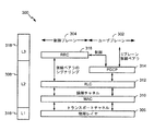
ワイヤレス遠隔通信システムでは、通信プロトコルアーキテクチャは、特定のアプリケーションに応じて様々な形態をとることができる。たとえば、3GPP UMTSシステムでは、シグナリングプロトコルスタックは、非アクセス層(NAS)とアクセス層(AS)とに分けられる。NASは、UE 210とコアネットワーク204との間のシグナリングのために上位層を提供し(図2参照)、回線交換プロトコルとパケット交換プロトコルとを含むことができる。ASは、UTRAN 202とUE 210との間のシグナリングのために下位層を提供し、ユーザプレーンと制御プレーンとを含むことができる。ここで、ユーザプレーンまたはデータプレーンはユーザのトラフィックを搬送し、一方、制御プレーンは、制御情報(すなわちシグナリング)を搬送する。
In a wireless telecommunications system, the communication protocol architecture can take a variety of forms depending on the particular application. For example, in a 3GPP UMTS system, the signaling protocol stack is divided into a non-access layer (NAS) and an access layer (AS). The NAS provides an upper layer for signaling between the
図5を参照すると、ユーザ機器(UE)またはノードB/基地局のユーザプレーン302と制御プレーン304とに関する例示的な無線プロトコルアーキテクチャ300におけるL1 316と、L2 308と、L3 318との3つのレイヤをもつアクセス層(AS:access stratum)が示されている。たとえば、アーキテクチャ300は、第1の通信装置1002、第2の通信装置1004、または装置100(図1および図3参照)中に含まれるか、あるいはUE 210またはノードB 208(図4参照)中に含まれ得る。
Referring to FIG. 5, the three layers of
層1 316は最下層であり、様々な物理層の信号処理機能を実装する。層1 316は、本明細書では物理層306と呼ばれる。層2 308と呼ばれるデータリンク層は、物理層306の上にあり、物理層306を通じたUE 210とノードB 208との間のリンクを担う。
Layer 1 316 is the lowest layer and implements various physical layer signal processing functions. Layer 1 316 is referred to herein as
層3において、RRC層316は、UE 210とノードB 208との間の制御プレーンのシグナリングを取り扱う。RRC層316は、高次層のメッセージのルーティング、ブロードキャスト機能および呼び出し機能の取り扱い、無線ベアラの確立および構成などのための、いくつかの機能的なエンティティを含む。
At layer 3, the
示されるエアインターフェースでは、L2層308はサブレイヤに分割される。制御プレーンでは、L2層308は、メディアアクセス制御(MAC)サブレイヤ310および無線リンク制御(RLC)サブレイヤ312という、2つのサブレイヤを含む。ユーザプレーンでは、L2層308はさらに、パケットデータコンバージェンスプロトコル(PDCP)サブレイヤ314を含む。示されないが、UEは、ネットワーク側のPDNゲートウェイで終端するネットワーク層(たとえばIP層)と、接続の他の端部(たとえば、遠端のUE、サーバなど)で終端するアプリケーション層とを含めて、L2層308より上にいくつかの上位層を有し得る。
In the air interface shown, the
PDCPサブレイヤ314は、異なる無線ベアラと論理チャネルとの間の多重化を行う。PDCPサブレイヤ314はまた、無線送信のオーバーヘッドを低減するための上位層データパケットのヘッダ圧縮、データパケットの暗号化によるセキュリティ、および、ノードB間のUEのハンドオーバーのサポートを実現する。
The
RLCサブレイヤ312は、一般に、確認型モード(AM)(肯定応答および再送信処理がエラー訂正のために使用され得る)、非確認型モード(UM)、およびデータ転送のための透過型モードをサポートし、上位層のデータパケットのセグメント化およびリアセンブリと、MAC層におけるハイブリッド自動反復要求(HARQ)による順序の乱れた受信を補償するためのデータパケットの並べ替え(reordering)を提供する。確認型モードでは、RNCおよびUEなどのRLCピアエンティティは、特にRLCデータPDU、RLCステータスPDU、およびRLCリセットPDUを含む様々なRLCプロトコルデータユニット(PDU)を交換することができる。本開示では、「パケット」という用語は、RLCピアエンティティ間で交換される任意のRLC PDUを指すことがある。
MACサブレイヤ310は、論理チャネルとトランスポートチャネルとの間の多重化を行う。MACサブレイヤ310はまた、1つのセルの中の様々な無線リソース(たとえばリソースブロック)を複数のUE間で割り当てる役割を担う。MACサブレイヤ310はまた、HARQ動作も担う。
The
MACサブレイヤ310は、限定はされないが、MAC-dエンティティおよびMAC-hs/ehsエンティティを含む、様々なMACエンティティを含む。無線ネットワークコントローラ(RNC:Radio Network Controller)は、MAC-dおよび上記からのプロトコルレイヤを収容する。高速チャネルについて、MAC-hs/ehsレイヤがノードBに収容される。
The
UE側から、MAC-dエンティティは、すべての専用トランスポートチャネル、MAC-c/sh/mエンティティ、およびMAC-hs/ehsエンティティへのアクセスを制御するように構成される。さらに、UE側から、MAC-hs/ehsエンティティは、HSDPA特有の機能を扱い、HS-DSCHトランスポートチャネルへのアクセスを制御するように構成される。上位レイヤは、HS-DSCH機能を扱うのにMAC-hsとMAC-ehsという2つのエンティティのどちらが適用されるかを設定する。 From the UE side, the MAC-d entity is configured to control access to all dedicated transport channels, MAC-c / sh / m entities, and MAC-hs / ehs entities. In addition, from the UE side, the MAC-hs / ehs entity handles HSDPA specific functions and is configured to control access to the HS-DSCH transport channel. The upper layer sets which of two entities, MAC-hs and MAC-ehs, is applied to handle the HS-DSCH function.
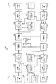
図6を参照すると、ワイヤレス通信エンティティのうちの1つまたは複数、たとえば、UEおよび/または基地局が、たとえば、第1の通信装置1002、第2の通信装置1004、UE 210、ノードB 208、送信RLC UMエンティティ1006、MACエンティティ1014、受信RLC UMエンティティ1018、または装置100(図1、図3、および図4参照)を含み得る、UTRANアーキテクチャ中のアクセスネットワーク300が示されている。
Referring to FIG. 6, one or more of the wireless communication entities, e.g., the UE and / or the base station, are e.g., a
システムは、セル302、304、および306を含む複数のセルラー領域(セル)を含み、セルの各々は、1つまたは複数のセクタを含み得る。セルは、(たとえばカバレージエリアによって)地理的に定義することができ、かつ/または、周波数、スクランブリングコードなどに従って定義することもできる。つまり、図示される地理的に定義されたセル302、304、および306は各々、たとえば異なるスクランブリングコードを利用することによって、複数のセルにさらに分割され得る。たとえば、セル304aは、第1のスクランブリングコードを利用することができ、セル304bは、同じ地理的な領域内にあり同じノードB 344によってサービスされているとき、第2のスクランブリングコードを利用することによって区別され得る。
The system includes a plurality of cellular regions (cells) that include
セクタに分割されるセルでは、セル内の複数のセクタはアンテナのグループによって形成されてよく、各々のアンテナがセルの一部にあるUEとの通信を担う。たとえば、セル302において、アンテナグループ312、314、および316は、各々異なるセクタに対応し得る。セル304において、アンテナグループ318、320、および322は、各々異なるセクタに対応することができる。セル306において、アンテナグループ324、326、および328は、各々異なるセクタに対応することができる。
In a cell divided into sectors, a plurality of sectors in the cell may be formed by a group of antennas, each antenna responsible for communication with UEs that are part of the cell. For example, in
セル302、304、および306は、各セル302、304、または306の1つまたは複数のセクタと通信中であり得る、いくつかのUEを含み得る。たとえば、UE330および332はノードB342と通信していることがあり、UE334および336はノードB344と通信していることがあり、UE338および340はノードB346と通信していることがある。ここで、各ノードB342、344、および346は、それぞれのセル302、304、および306の中のすべてのUE330、332、334、336、338、および340のために、コアネットワーク204(図4参照)へのアクセスポイントを提供するように構成され得る。
ソースセルとの呼の間、または任意の他の時間において、UE 336は、近隣のセルの様々なパラメータとともに、ソースセルの様々なパラメータを監視することができる。さらに、これらのパラメータの品質に応じて、UE 336は、近隣セルの1つまたは複数との通信を保つことができる。この期間において、UE 336は、UE 336が同時に接続されるセルのリストであるアクティブセットを保持することができる(すなわち、ダウンリンク専用物理チャネルDPCHまたはフラクショナルダウンリンク専用物理チャネルF-DPCHを現在UE 336に割り当てているUTRANセルが、アクティブセットを構成し得る)。
During a call with the source cell, or at any other time, the
図7は、UE 750と通信しているノードB 710を含む電気通信システム700のブロック図であり、ここで、ノードB 710とUE 750とは、第1の通信装置1002、第2の通信装置1004、UE 210、ノードB 208、送信RLC UMエンティティ1006、受信RLC UMエンティティ1018、MACエンティティ1014、または装置100(図1、図3、および図4参照)を含み得る。
FIG. 7 is a block diagram of a
ダウンリンク通信では、送信プロセッサ720は、データ源712からデータを受信し、コントローラ/プロセッサ740から制御信号を受信することができる。送信プロセッサ720は、参照信号(たとえばパイロット信号)とともに、データ信号および制御信号のための様々な信号処理機能を提供する。たとえば、送信プロセッサ720は、誤り検出のための巡回冗長検査(CRC)コード、順方向誤り訂正(FEC)を支援するための符号化およびインターリービング、様々な変調方式(たとえば、二位相偏移変調(BPSK)、四位相偏移変調(QPSK)、M-位相偏移変調(M-PSK)、M-直角位相振幅変調(M-QAM)など)に基づいた信号配列へのマッピング、直交可変拡散率(OVSF)による拡散、および、一連のシンボルを生成するためのスクランブリングコードとの乗算を、提供することができる。送信プロセッサ720のための、符号化方式、変調方式、拡散方式および/またはスクランブリング方式を決定するために、チャネルプロセッサ744からのチャネル推定が、コントローラ/プロセッサ740によって使われ得る。これらのチャネル推定は、UE 750によって送信される参照信号から、またはUE 750からのフィードバックから、導出され得る。送信プロセッサ720によって生成されたシンボルは、フレーム構造を作成するために、送信フレームプロセッサ730に与えられる。送信フレームプロセッサ730は、コントローラ/プロセッサ740からの情報とシンボルとを多重化することによって、このフレーム構造を作成し、一連のフレームが得られる。次いでこれらフレームは送信機732に与えられ、送信機732は、アンテナ734を通じたワイヤレス媒体によるダウンリンク送信のために、増幅、フィルタリング、およびフレームのキャリア上への変調を含む、様々な信号調整機能を提供する。アンテナ734は、たとえば、ビームステアリング双方向適応アンテナアレイまたは他の同様のビーム技術を含む、1つまたは複数のアンテナを含み得る。
For downlink communication, the transmit
UE 750において、受信機754は、アンテナ752を通じてダウンリンク送信を受信し、その送信を処理してキャリア上へ変調されている情報を回復する。受信機754によって回復された情報は、受信フレームプロセッサ760に与えられ、受信フレームプロセッサ760は、各フレームを解析し、フレームからの情報をチャネルプロセッサ794に提供し、データ信号、制御信号、および参照信号を受信プロセッサ770に提供する。受信プロセッサ770は次いで、ノードB 710中の送信プロセッサ720によって実行される処理の逆を実行する。より具体的には、受信プロセッサ770は、シンボルを逆スクランブルおよび逆拡散し、次いで変調方式に基づいて、ノードB 710によって送信された、最も可能性の高い信号配列点を求める。これらの軟判定は、チャネルプロセッサ794によって計算されるチャネル推定に基づき得る。そして軟判定は、データ信号、制御信号、および参照信号を回復するために、復号されてデインターリーブされる。そして、フレームの復号が成功したかどうか判定するために、CRCコードが確認される。次いで、復号に成功したフレームによって搬送されるデータがデータシンク772に与えられ、データシンク772は、UE 750および/または様々なユーザインターフェース(たとえばディスプレイ)において実行されているアプリケーションを表す。復号に成功したフレームが搬送する制御信号は、コントローラ/プロセッサ790に与えられる。受信プロセッサ770によるフレームの復号が失敗すると、コントローラ/プロセッサ790は、確認応答(ACK)プロトコルおよび/または否定応答(NACK)プロトコルを用いて、そうしたフレームの再送信要求をサポートすることもできる。
At
アップリンクでは、データ源778からのデータおよびコントローラ/プロセッサ790からの制御信号が、送信プロセッサ780に与えられる。データ源778は、UE 750で実行されているアプリケーションおよび様々なユーザインターフェース(たとえばキーボード)を表し得る。ノードB 710によるダウンリンク送信に関して説明される機能と同様に、送信プロセッサ780は、CRCコード、FECを支援するための符号化およびインターリービング、信号配列へのマッピング、OVSFによる拡散、および、一連のシンボルを生成するためのスクランブリングを含む、様々な信号処理機能を提供する。ノードB 710によって送信される参照信号から、または、ノードB 710によって送信されるミッドアンブル中に含まれるフィードバックから、チャネルプロセッサ794によって導出されるチャネル推定が、適切な符号化方式、変調方式、拡散方式、および/またはスクランブリング方式を選択するために、使われ得る。送信プロセッサ780によって生成されたシンボルは、フレーム構造を作成するために、送信フレームプロセッサ782に与えられる。送信フレームプロセッサ782は、コントローラ/プロセッサ790からの情報とシンボルとを多重化することによって、このフレーム構造を作成し、一連のフレームが得られる。次いでこのフレームは送信機756に与えられ、送信機756は、アンテナ752を通じたワイヤレス媒体によるアップリンク送信のために、増幅、フィルタリング、およびフレームのキャリア上への変調を含む、様々な信号調整機能を提供する。
On the uplink, data from
アップリンク送信は、UE 750において受信機能に関して説明されたのと同様の方式で、ノードB 710において処理される。受信機735は、アンテナ734を通じてアップリンク送信を受信し、その送信を処理してキャリア上へ変調されている情報を回復する。受信機735によって回復された情報は、受信フレームプロセッサ736に与えられ、受信フレームプロセッサ736は、各フレームを解析し、フレームからの情報をチャネルプロセッサ744に提供し、データ信号、制御信号、および参照信号を受信プロセッサ738に提供する。受信プロセッサ738は、UE 750中の送信プロセッサ780によって実行される処理の逆を実行する。次いで、復号に成功したフレームによって搬送されるデータ信号および制御信号が、データシンク739およびコントローラ/プロセッサにそれぞれ与えられ得る。フレームの一部が、受信プロセッサによる復号に失敗すると、コントローラ/プロセッサ740は、確認応答(ACK)プロトコルおよび/または否定応答(NACK)プロトコルを用いて、そうしたフレームの再送信要求をサポートすることもできる。
Uplink transmissions are processed at
コントローラ/プロセッサ740および790は、それぞれノードB 710およびUE 750における動作を指示するために使われ得る。たとえば、コントローラ/プロセッサ740および790は、タイミング、周辺インターフェース、電圧調整、電力管理、および他の制御機能を含む、様々な機能を提供することができる。メモリ742および792のコンピュータ可読媒体は、それぞれ、ノードB 710およびUE 750のためのデータおよびソフトウェアを記憶することができる。ノードB 710におけるスケジューラ/プロセッサ746は、リソースをUEに割り当て、UEのダウンリンク送信および/またはアップリンク送信をスケジューリングするために、使われ得る。
Controllers /
高速パケットアクセス(HSPA)エアインターフェースは、ユーザに対してスループットの向上および待ち時間の低減を支援する、UE 750とノードB 710との間の3G/W-CDMAエアインターフェースに対する一連の強化を含む。前の規格に対する他の修正の中でも、HSPAは、ハイブリッド自動再送要求(HARQ)、チャネル送信の共有、ならびに適応変調および適応符号化を利用する。HSPAを定義する規格は、HSDPA(高速ダウンリンクパケットアクセス)およびHSUPA(高速アップリンクパケットアクセス、改良型アップリンクまたはEULとも呼ばれる)を含む。
The High Speed Packet Access (HSPA) air interface includes a series of enhancements to the 3G / W-CDMA air interface between the
たとえば、3GPP規格ファミリーのリリース5では、HSDPAが導入された。HSDPAは、いくつかのUEによって共有され得る高速ダウンリンク共有チャネル(HS-DSCH)を、トランスポートチャネルとして利用する。HS-DSCHは、高速物理ダウンリンク共有チャネル(HS-PDSCH)、高速共有制御チャネル(HS-SCCH)、および高速専用物理制御チャネル(HS-DPCCH)という、3つの物理チャネルによって実装される。 For example, Release 5 of the 3GPP standard family introduced HSDPA. HSDPA utilizes a high speed downlink shared channel (HS-DSCH) that can be shared by several UEs as a transport channel. HS-DSCH is implemented by three physical channels: a high-speed physical downlink shared channel (HS-PDSCH), a high-speed shared control channel (HS-SCCH), and a high-speed dedicated physical control channel (HS-DPCCH).
HS-SCCHは、HS-DSCHの送信に関連するダウンリンク制御情報を搬送するために利用され得る、物理チャネルである。ここで、HS-DSCHは、1つまたは複数のHS-SCCHと関連付けられ得る。UEは、いつHS-DSCHからデータを読み取るべきかを決定するため、および、割り当てられる物理チャネルにおいて用いられる変調方式を決定するために、HS-SCCHを継続的に監視することができる。 HS-SCCH is a physical channel that can be utilized to carry downlink control information related to transmission of HS-DSCH. Here, the HS-DSCH may be associated with one or more HS-SCCHs. The UE can continuously monitor the HS-SCCH to determine when to read data from the HS-DSCH and to determine the modulation scheme used in the assigned physical channel.
HS-PDSCHは、いくつかのUEによって共有され得、かつ高速ダウンリンクに対するダウンリンクデータを搬送することができる物理チャネルである。HS-PDSCHは、四位相偏移変調(QPSK)、16-直角位相振幅変調(16-QAM)、およびマルチコード送信をサポートすることができる。 HS-PDSCH is a physical channel that can be shared by several UEs and can carry downlink data for high speed downlink. HS-PDSCH can support quadrature phase shift keying (QPSK), 16-quadrature amplitude modulation (16-QAM), and multi-code transmission.
HS-DPCCHは、そのスケジューリングアルゴリズムにおいてノードBを支援するためにUEからのフィードバックを搬送することができる、アップリンク物理チャネルである。フィードバックは、チャネル品質インジケータ(CQI)と、前のHS-DSCH送信の肯定応答または否定応答(ACK/NAK)とを含み得る。 HS-DPCCH is an uplink physical channel that can carry feedback from the UE to assist Node B in its scheduling algorithm. The feedback may include a channel quality indicator (CQI) and an acknowledgment or negative acknowledgment (ACK / NAK) of the previous HS-DSCH transmission.
リリース5のHSDPAと、前に規格化された回線交換エアインターフェースとの、ダウンリンクにおける1つの違いは、HSDPAにはソフトハンドオーバがないことである。このことは、HSDPAチャネルが、HSDPAサービングセルと呼ばれる単一のセルからUEに送信されることを意味する。ユーザが移動すると、またはあるセルが別のセルよりも好ましくなると、HSDPAサービングセルは変わり得る。それでも、UEは関連するDPCH上でソフトハンドオーバの状態にあることがあり、複数のセルから同じ情報を受信する。 One difference in the downlink between Release 5 HSDPA and the previously standardized circuit switched air interface is that HSDPA has no soft handover. This means that the HSDPA channel is transmitted to the UE from a single cell called the HSDPA serving cell. The HSDPA serving cell may change as the user moves or when one cell becomes more favorable than another. Still, the UE may be in soft handover on the associated DPCH and receives the same information from multiple cells.
リリース5のHSDPAでは、任意の瞬間において、UE 210は1つのサービングセルを有し、Ec/I0のUE測定によれば、そのサービングセルがアクティブセット中で最強のセルである。3GPP TS 25.331のリリース5で定められるモビリティ手順によれば、HSPDAサービングセルを変更するための無線リソース制御(RRC)シグナリングメッセージが、より強いセルであるとUEが報告するセル(すなわちターゲットセル)からではなく、現在のHSDPAサービングセル(すなわちソースセル)から送信される。
In Release 5 HSDPA, at any moment, the
3GPPのリリース6の規格は、拡張アップリンク(EUL)または高速アップリンクパケットアクセス(HSUPA)と呼ばれる、アップリンクの拡張を導入した。HSUPAは、EUL専用チャネル(E-DCH)をトランスポートチャネルとして利用する。E-DCHは、リリース99のDCHとともに、アップリンクで送信される。DCHの制御部分、すなわちDPCCHは、パイロットビットおよびダウンリンク電力制御命令を、アップリンク送信で搬送する。 The 3GPP Release 6 standard introduced an uplink extension called Enhanced Uplink (EUL) or High Speed Uplink Packet Access (HSUPA). HSUPA uses an EUL dedicated channel (E-DCH) as a transport channel. The E-DCH is transmitted on the uplink along with the Release 99 DCH. The control part of DCH, ie DPCCH, carries pilot bits and downlink power control commands in uplink transmission.
E-DCHは、E-DCH専用物理データチャネル(E-DPDCH)およびE-DCH専用物理制御チャネル(E-DPCCH)を含む物理チャネルによって実装される。加えて、HSUPAは、E-DCH HARQインジケータチャネル(E-HICH)、E-DCH絶対許可チャネル(E-AGCH)、およびE-DCH相対許可チャネル(E-RGCH)を含む、追加の物理チャネルを利用する。 E-DCH is implemented by physical channels including E-DCH dedicated physical data channel (E-DPDCH) and E-DCH dedicated physical control channel (E-DPCCH). In addition, HSUPA provides additional physical channels, including E-DCH HARQ indicator channel (E-HICH), E-DCH absolute grant channel (E-AGCH), and E-DCH relative grant channel (E-RGCH). Use.
W-CDMAシステムを参照して、遠隔通信システムのいくつかの態様を示してきた。当業者が容易に諒解するように、本開示全体にわたって説明される様々な態様は、他の遠隔通信システム、ネットワークアーキテクチャおよび通信規格に拡張され得る。 Several aspects of telecommunications systems have been shown with reference to W-CDMA systems. As those skilled in the art will readily appreciate, the various aspects described throughout this disclosure can be extended to other telecommunications systems, network architectures and communication standards.
例として、様々な態様は、TD-SCDMAおよびTD-CDMAのような、他のUMTSシステムに拡張され得る。様々な態様はまた、(FDD、TDD、またはこれら両方のモードの)Long Term Evolution(LTE)、(FDD、TDD、またはこれら両方のモードの)LTE-Advanced(LTE-A)、CDMA2000、Evolution-Data Optimized(EV-DO)、Ultra Mobile Broadband(UMB)、IEEE 802.11(Wi-Fi)、IEEE 802.16(WiMAX)、IEEE 802.20、Ultra-Wideband(UWB)、Bluetooth(登録商標)、および/または他の適切なシステムを利用する、システムに拡張され得る。実際の利用される遠隔通信規格、ネットワークアーキテクチャ、および/または通信規格は、具体的な用途およびシステム全体に課される設計制約に依存する。 As an example, various aspects can be extended to other UMTS systems, such as TD-SCDMA and TD-CDMA. Various aspects also include Long Term Evolution (LTE) (for FDD, TDD, or both modes), LTE-Advanced (LTE-A) (for FDD, TDD, or both modes), CDMA2000, Evolution- Data Optimized (EV-DO), Ultra Mobile Broadband (UMB), IEEE 802.11 (Wi-Fi), IEEE 802.16 (WiMAX), IEEE 802.20, Ultra-Wideband (UWB), Bluetooth, and / or other It can be extended to a system using an appropriate system. The actual telecommunication standard, network architecture, and / or communication standard utilized will depend on the specific application and design constraints imposed on the overall system.
開示した方法におけるステップの特定の順序または階層は例示的な処理を示していることを理解されたい。設計上の選好に基づいて、方法におけるステップの特定の順序または階層は再構成可能であることを理解されたい。添付の方法クレームは、サンプル的順序で様々なステップの要素を提示しており、クレーム内で明記していない限り、提示した特定の順序または階層に限定されるように意図されているわけではない。 It should be understood that the specific order or hierarchy of steps in the disclosed methods represents an exemplary process. It should be understood that the specific order or hierarchy of steps in the method is reconfigurable based on design preferences. The accompanying method claims present elements of the various steps in a sample order, and are not intended to be limited to the specific order or hierarchy presented unless explicitly stated in the claims. .
上記の説明は、本明細書で説明される様々な態様を当業者が実施できるようにするために与えられる。これらの態様への様々な変更は当業者には容易に明らかであり、本明細書で定義した一般的原理は他の態様に適用され得る。したがって、請求項は本明細書で示す態様に限定されるよう意図されているわけではなく、請求項の文言と整合するすべての範囲を許容するように意図されており、単数の要素への言及は、そのように明記されていない限り、「唯一無二の」ではなく、「1つまたは複数の」を意味するよう意図されている。別段に明記されていない限り、「いくつかの」という用語は「1つまたは複数の」を意味する。項目の列挙「のうちの少なくとも1つ」という語句は、単一の要素を含め、それらの項目の任意の組合せを意味する。たとえば、「a、bまたはcのうちの少なくとも1つ」は、「a」、「b」、「c」、「aおよびb」、「aおよびc」、「bおよびc」、「a、bおよびc」を含むことが意図されている。当業者が知っているか、後に知ることになる、本開示全体にわたって説明された様々な態様の要素と構造的かつ機能的に同等のものはすべて、参照により本明細書に明確に組み込まれ、請求項によって包含されることが意図される。また、本明細書で開示する内容は、そのような開示が請求項で明記されているか否かに関わりなく、公に供することは意図されていない。請求項のいかなる要素も、「のための手段」という語句を使用して要素が明記されている場合、または方法クレームで「のためのステップ」という語句を使用して要素が記載されている場合を除き、米国特許法第112条第6項の規定に基づき解釈されることはない。 The above description is provided to enable any person skilled in the art to implement various aspects described herein. Various modifications to these aspects will be readily apparent to those skilled in the art, and the generic principles defined herein may be applied to other aspects. Thus, the claims are not intended to be limited to the embodiments shown herein, but are intended to allow the full scope consistent with the language of the claims and reference to a singular element. Is intended to mean "one or more", not "one and only one", unless so specified. Unless otherwise specified, the term “several” means “one or more”. The phrase “at least one of” a list of items means any combination of those items, including a single element. For example, “at least one of a, b or c” means “a”, “b”, “c”, “a and b”, “a and c”, “b and c”, “a, It is intended to include “b and c”. All structurally and functionally equivalent elements of the various aspects described throughout this disclosure that will be known or later known by those skilled in the art are expressly incorporated herein by reference and are claimed. It is intended to be covered by the terms. Also, the content disclosed herein is not intended to be publicly available regardless of whether such disclosure is expressly recited in the claims. Any element of a claim is specified using the phrase “means for” or the element is described using the phrase “steps for” in a method claim Except for the above, no interpretation shall be made under the provisions of Article 112 (6) of the US Patent Act.
100 装置
102 バス
104 プロセッサ
105 メモリ
106 コンピュータ可読媒体
108 バスインターフェース
110 トランシーバ
112 ユーザインターフェース
114 処理システム
116 RLC/MAC UMエンティティ
118 MACエンティティ
200 Universal Mobile Telecommunications System(UMTS)システム
202 UMTS地上波無線アクセスネットワーク(UTRAN)
204 コアネットワーク
206 無線ネットワークコントローラ(RNC)
207 無線ネットワークサブシステム(RNS)
208 ノードB
210 ユーザ機器(UE)
211 汎用加入者識別モジュール(USIM)
212 モバイルサービス交換センタ(MSC)
214 ゲートウェイMSC(GMSC)
215 ホームロケーションレジスタ(HLR)
216 回線交換ネットワーク
218 サービングGPRSサポートノード(SGSN)
220 ゲートウェイGPRSサポートノード(GGSN)
222 パケットベースネットワーク
300 無線プロトコルアーキテクチャ、アーキテクチャ
302 ユーザプレーン
302 セル
304 制御プレーン
304、304a、304b セル
306 セル
306 物理層
308 L2、層2、L2層、データリンク層
310 メディアアクセス制御(MAC)サブレイヤ、MACサブレイヤ
312 無線リンク制御(RLC)サブレイヤ
312 アンテナグループ
314 パケットデータコンバージェンスプロトコル(PDCP)サブレイヤ
314 アンテナグループ
316 L1、RRC層
316 アンテナグループ
318 L3
318 アンテナグループ
320 アンテナグループ
322 アンテナグループ
324 アンテナグループ
326 アンテナグループ
328 アンテナグループ
330 UE
332 UE
334 UE
336 UE
338 UE
340 UE
342 ノードB
344 ノードB
346 ノードB
700 電気通信システム
710 ノードB
712 データ源
720 送信プロセッサ
730 送信フレームプロセッサ
732 送信機
734 アンテナ
735 受信機
736 受信フレームプロセッサ
738 受信プロセッサ
739 データシンク
740 コントローラ/プロセッサ
742 メモリ
744 チャネルプロセッサ
746 スケジューラ/プロセッサ
750 ユーザ機器(UE)
752 アンテナ
754 受信機
756 送信機
760 受信フレームプロセッサ
770 受信プロセッサ
772 データシンク
778 データ源
780 送信プロセッサ
782 送信フレームプロセッサ
790 コントローラ/プロセッサ
792 メモリ
794 チャネルプロセッサ
1000 システム
1002 第1の通信装置
1004 第2の通信装置
1006 送信RLC UMエンティティ
1008 PDU送信ステータスの履歴
1010 送信機RLC UM SN
1012 送信機HFN
1014 MACエンティティ
1016 HARQエンティティ
1018 受信RLC UMエンティティ
1020 受信機HFN
1022 HFN非同期条件
1024 受信機RLC UM SN
1024 HFN非同期条件判断構成要素
1026 HFN調整構成要素
1028 送信ステータス判断構成要素
1030 送信ステータスマッピング構成要素
100 devices
102 bus
104 processor
105 memory
106 Computer-readable media
108 Bus interface
110 transceiver
112 User interface
114 treatment system
116 RLC / MAC UM entity
118 MAC entity
200 Universal Mobile Telecommunications System (UMTS) system
202 UMTS Terrestrial Radio Access Network (UTRAN)
204 Core network
206 Radio Network Controller (RNC)
207 Radio Network Subsystem (RNS)
208 Node B
210 User equipment (UE)
211 Universal Subscriber Identification Module (USIM)
212 Mobile Service Exchange Center (MSC)
214 Gateway MSC (GMSC)
215 Home Location Register (HLR)
216 circuit switched network
218 Serving GPRS Support Node (SGSN)
220 Gateway GPRS support node (GGSN)
222 packet-based network
300 Wireless protocol architecture, architecture
302 User plane
302 cells
304 control plane
304, 304a, 304b cells
306 cells
306 Physical layer
308 L2, Layer 2, L2 layer, Data link layer
310 Media Access Control (MAC) sublayer, MAC sublayer
312 Radio Link Control (RLC) sublayer
312 Antenna group
314 Packet Data Convergence Protocol (PDCP) sublayer
314 Antenna group
316 L1, RRC layer
316 Antenna group
318 L3
318 Antenna group
320 Antenna group
322 Antenna group
324 Antenna group
326 Antenna Group
328 Antenna group
330 UE
332 UE
334 UE
336 UE
338 UE
340 UE
342 Node B
344 Node B
346 Node B
700 Telecommunications system
710 Node B
712 data sources
720 transmit processor
730 Transmit frame processor
732 transmitter
734 antenna
735 receiver
736 Receive frame processor
738 Receive processor
739 Data sync
740 controller / processor
742 memory
744 channel processor
746 Scheduler / Processor
750 User equipment (UE)
752 antenna
754 receiver
756 transmitter
760 receive frame processor
770 receive processor
772 Data Sync
778 Data Source
780 transmit processor
782 Transmit frame processor
790 Controller / Processor
792 memory
794 channel processor
1000 system
1002 First communication device
1004 Second communication device
1006 Outgoing RLC UM entity
1008 PDU transmission status history
1010 Transmitter RLC UM SN
1012 Transmitter HFN
1014 MAC entity
1016 HARQ entity
1018 Incoming RLC UM entity
1020 receiver HFN
1022 HFN asynchronous condition
1024 receiver RLC UM SN
1024 HFN asynchronous condition determination component
1026 HFN adjustment components
1028 Transmission status determination component
1030 Transmission status mapping component
Claims (18)
前記RLC UMで動作している前記送信機によって、ハイパーフレーム番号(HFN)非同期条件を判断するステップであって、複数の連続するプロトコルデータユニット(PDU)のうちの少なくとも1つのPDUが前記受信機に前記送信機によって正常に送信されたときに前記HFN非同期条件が偽となり、前記複数の連続するPDUのすべてが失われたときに前記HFN非同期条件が真となり、前記複数の連続するPDUの数がRLC UMシーケンス番号の全周期の2以上の倍数に等しい、判断するステップと、
前記HFN非同期条件が真であることに応答して、前記RLC UMで動作している前記送信機が送信機HFNの値から前記倍数の値を減算することによって前記送信機の送信機HFNを調整するステップであって、前記調整された送信機HFNが前記RLC UMにおいて送信されるべき新しいPDUのために使用される、調整するステップと
を含む、方法。 A method of data communication between a transmitter and a receiver in radio link control (RLC) unacknowledged mode (UM),
Determining a hyperframe number (HFN) asynchronous condition by the transmitter operating in the RLC UM, wherein at least one PDU of a plurality of consecutive protocol data units (PDUs) is the receiver the number of the said HFN un-synchronization condition when it is successfully transmitted by the transmitter becomes false, the HFN un-synchronization condition is true when all of the plurality of consecutive PDU is lost, the plurality of consecutive PDU to There is equal to a multiple of 2 or more of the total period of the R LC UM sequence number, and determining,
In response to the HFN asynchronous condition being true, the transmitter operating in the RLC UM adjusts the transmitter HFN of the transmitter by subtracting the multiple value from the value of the transmitter HFN. Adjusting, wherein the adjusted transmitter HFN is used for a new PDU to be transmitted in the RLC UM.
前記送信機のRLCサブレイヤによって、メディアアクセス制御(MAC)サブレイヤ中のPDUの送信ステータスに基づいて前記PDUの成功または不成功の送信ステータスを判断するステップと、
前記RLCサブレイヤによって、前記複数の連続するPDUに前記成功または不成功の送信ステータスをマッピングするステップと
を含む、請求項1に記載の方法。 The step of determining comprises:
Determining, by the RLC sublayer of the transmitter, the successful or unsuccessful transmission status of the PDU based on the transmission status of the PDU in a Media Access Control (MAC) sublayer;
Mapping the successful or unsuccessful transmission status to the plurality of consecutive PDUs by the RLC sublayer.
前記受信機の受信機HFNと前記送信機HFNを同期させるように前記送信機HFNを調整するステップであって、前記送信機と前記受信機とが、同じHFNと、同じRLC UMシーケンス番号とを使用するとき、前記送信機および前記受信機の暗号化および解読パラメータが同期される、調整するステップ
を含む、請求項1に記載の方法。 The step of adjusting the transmitter HFN comprises:
Adjusting the transmitter HFN to synchronize the receiver HFN and the transmitter HFN of the receiver, wherein the transmitter and the receiver have the same HFN and the same RLC UM sequence number; The method of claim 1, comprising adjusting, when used, encryption and decryption parameters of the transmitter and the receiver are synchronized.
前記送信機HFNの値から前記倍数の値を減算するステップ
を含む、請求項1に記載の方法。 The step of adjusting the transmitter HFN comprises:
The method of claim 1, comprising subtracting the multiple value from the transmitter HFN value .
前記RLC UMで動作している前記送信機によって、ハイパーフレーム番号(HFN)非同期条件を判断するためのコードであって、複数の連続するプロトコルデータユニット(PDU)のうちの少なくとも1つのPDUが前記受信機に前記送信機によって正常に送信されたときに前記HFN非同期条件が偽となり、前記複数の連続するPDUのすべてが失われたときに前記HFN非同期条件が真となり、前記複数の連続するPDUの数がRLC UMシーケンス番号の全周期の2以上の倍数に等しい、判断するためのコードと、
前記HFN非同期条件が真であるとき、前記RLC UMで動作している前記送信機によって前記送信機の送信機HFNを調整するためのコードであって、前記調整された送信機HFNが前記RLC UMにおいて送信されるべき新しいPDUのために使用される、調整するためのコードと
を含む、コンピュータ可読記録媒体。 A computer-readable recording medium storing computer-executable code for data communication between a transmitter and a receiver in radio link control (RLC) unacknowledged mode (UM),
A code for determining a hyperframe number (HFN) asynchronous condition by the transmitter operating in the RLC UM, wherein at least one PDU of a plurality of consecutive protocol data units (PDUs) is the wherein when it is successfully transmitted by said transmitter to a receiver HFN un-synchronization condition becomes false, the HFN un-synchronization condition when all of the plurality of consecutive PDU is lost is true and the plurality of consecutive PDU the number is equal to 2 or more times the number of full cycle of R LC UM sequence number, code for determining,
A code for adjusting the transmitter HFN of the transmitter by the transmitter operating in the RLC UM when the HFN asynchronous condition is true, wherein the adjusted transmitter HFN is the RLC UM A computer readable recording medium comprising: a coordinating code used for a new PDU to be transmitted at.
実行可能命令を記憶した少なくとも1つのプロセッサに結合されたメモリと、
前記メモリと通信する前記少なくとも1つのプロセッサと
を含み、
前記少なくとも1つのプロセッサが、
前記RLC UMで動作している前記送信機によって、ハイパーフレーム番号(HFN)非同期条件を判断することであって、複数の連続するプロトコルデータユニット(PDU)のうちの少なくとも1つのPDUが前記受信機に前記送信機によって正常に送信されたときに前記HFN非同期条件が偽となり、前記複数の連続するPDUのすべてが失われたときに前記HFN非同期条件が真となり、前記複数の連続するPDUの数がRLC UMシーケンス番号の全周期の2以上の倍数に等しい、判断することと、
前記HFN非同期条件が真であるとき、前記RLC UMで動作している前記送信機によって前記送信機の送信機HFNを調整することであって、前記調整された送信機HFNが前記RLC UMにおいて送信されるべき新しいPDUのために使用される、調整することと
を行うための命令を実行するように構成される、装置。 An apparatus for data communication between a transmitter and a receiver in radio link control (RLC) unacknowledged mode (UM),
A memory coupled to at least one processor storing executable instructions;
The at least one processor in communication with the memory;
The at least one processor is:
Determining a hyperframe number (HFN) asynchronous condition by the transmitter operating in the RLC UM, wherein at least one PDU of a plurality of consecutive protocol data units (PDUs) is the receiver the number of the said HFN un-synchronization condition when it is successfully transmitted by the transmitter becomes false, the HFN un-synchronization condition is true when all of the plurality of consecutive PDU is lost, the plurality of consecutive PDU to There is equal to a multiple of 2 or more of the total period of the R LC UM sequence number, and to determine,
Adjusting the transmitter HFN of the transmitter by the transmitter operating in the RLC UM when the HFN asynchronous condition is true, wherein the adjusted transmitter HFN transmits in the RLC UM A device configured to execute instructions for coordinating and used for a new PDU to be performed.
前記RLC UMで動作している前記送信機によって、ハイパーフレーム番号(HFN)非同期条件を判断するための手段であって、複数の連続するプロトコルデータユニット(PDU)のうちの少なくとも1つのPDUが前記受信機に前記送信機によって正常に送信されたときに前記HFN非同期条件が偽となり、前記複数の連続するPDUのすべてが失われたときに前記HFN非同期条件が真となり、前記複数の連続するPDUの数がRLC UMシーケンス番号の全周期の2以上の倍数に等しい、判断するための手段と、
前記HFN非同期条件が真であるとき、前記RLC UMで動作している前記送信機によって前記送信機の送信機HFNを調整するための手段であって、前記調整された送信機HFNが前記RLC UMにおいて送信されるべき新しいPDUのために使用される、調整するための手段と
を含む、装置。 An apparatus for data communication between a transmitter and a receiver in radio link control (RLC) unacknowledged mode (UM),
Means for determining a hyperframe number (HFN) asynchronous condition by the transmitter operating in the RLC UM, wherein at least one PDU of a plurality of consecutive protocol data units (PDUs) is the wherein when it is successfully transmitted by said transmitter to a receiver HFN un-synchronization condition becomes false, the HFN un-synchronization condition when all of the plurality of consecutive PDU is lost is true and the plurality of consecutive PDU the number is equal to 2 or more times the number of full cycle of R LC UM sequence number, means for determining,
Means for adjusting a transmitter HFN of the transmitter by the transmitter operating in the RLC UM when the HFN asynchronous condition is true, wherein the adjusted transmitter HFN is the RLC UM Means for coordinating, used for new PDUs to be transmitted at.
前記送信機のRLCサブレイヤによって、メディアアクセス制御(MAC)サブレイヤ中のPDUの送信ステータスに基づいて前記PDUの成功または不成功の送信ステータスを判断することと、
前記RLCサブレイヤによって、前記複数の連続するPDUに前記成功または不成功の送信ステータスをマッピングすることと
を行うためのものである、請求項11に記載の装置。 The means for determining further comprises:
Determining by the RLC sublayer of the transmitter a successful or unsuccessful transmission status of the PDU based on the transmission status of the PDU in a Media Access Control (MAC) sublayer;
12. The apparatus according to claim 11, wherein the RLC sublayer is configured to perform mapping of the successful or unsuccessful transmission status to the plurality of consecutive PDUs.
Applications Claiming Priority (5)
| Application Number | Priority Date | Filing Date | Title |
|---|---|---|---|
| US201261712120P | 2012-10-10 | 2012-10-10 | |
| US61/712,120 | 2012-10-10 | ||
| US14/024,156 | 2013-09-11 | ||
| US14/024,156 US9313756B2 (en) | 2012-10-10 | 2013-09-11 | Apparatus and methods for managing hyper frame number (HFN) de-synchronization in radio link control (RLC) unacknowledged mode (UM) |
| PCT/US2013/059429 WO2014058560A1 (en) | 2012-10-10 | 2013-09-12 | Apparatus and methods for managing hyper frame number (hfn) de-synchronization in radio link control (rlc) unacknowledged mode (um) |
Publications (3)
| Publication Number | Publication Date |
|---|---|
| JP2015537432A JP2015537432A (en) | 2015-12-24 |
| JP2015537432A5 JP2015537432A5 (en) | 2016-08-25 |
| JP6099755B2 true JP6099755B2 (en) | 2017-03-22 |
Family
ID=50432629
Family Applications (1)
| Application Number | Title | Priority Date | Filing Date |
|---|---|---|---|
| JP2015536775A Expired - Fee Related JP6099755B2 (en) | 2012-10-10 | 2013-09-12 | Apparatus and method for managing hyperframe number (HFN) asynchrony in radio link control (RLC) unacknowledged mode (UM) |
Country Status (5)
| Country | Link |
|---|---|
| US (1) | US9313756B2 (en) |
| EP (1) | EP2907255A1 (en) |
| JP (1) | JP6099755B2 (en) |
| CN (1) | CN104718716B (en) |
| WO (1) | WO2014058560A1 (en) |
Families Citing this family (23)
| Publication number | Priority date | Publication date | Assignee | Title |
|---|---|---|---|---|
| US20140219451A1 (en) * | 2013-02-07 | 2014-08-07 | Mediatek Inc. | Adaptive security apparatus and method for updating security parameter |
| US9414399B2 (en) | 2013-02-07 | 2016-08-09 | Commscope Technologies Llc | Radio access networks |
| US9380466B2 (en) | 2013-02-07 | 2016-06-28 | Commscope Technologies Llc | Radio access networks |
| US9936470B2 (en) | 2013-02-07 | 2018-04-03 | Commscope Technologies Llc | Radio access networks |
| KR102265454B1 (en) * | 2014-04-11 | 2021-06-15 | 삼성전자 주식회사 | Apparatus and method for improving communication quality in mobile communication network |
| US10057916B2 (en) | 2014-06-09 | 2018-08-21 | Commscope Technologies Llc | Radio access networks in which mobile devices in the same communication cell can be scheduled to use the same airlink resource |
| US20150382395A1 (en) * | 2014-06-30 | 2015-12-31 | Alcatel-Lucent Usa Inc. | Method For Recovering From PDCP HFN De-Synchronization For VoLTE Call And Data Failure In RLC Layer |
| KR102202894B1 (en) * | 2014-08-28 | 2021-01-14 | 삼성전자 주식회사 | Apparatus and method for handling packet loss in a mobile communication system |
| US9532268B2 (en) * | 2014-11-19 | 2016-12-27 | Qualcomm Incorporated | Methods and apparatus for synchronizing a user equipment with an HFN offset |
| US10560842B2 (en) | 2015-01-28 | 2020-02-11 | Verint Systems Ltd. | System and method for combined network-side and off-air monitoring of wireless networks |
| US20160248908A1 (en) * | 2015-02-24 | 2016-08-25 | Qualcomm Incorporated | Voice garbling detection using silence insertion descriptor frames |
| US10470141B2 (en) | 2015-02-26 | 2019-11-05 | Telefonaktiebolaget Lm Ericsson (Publ) | Handling of hyper frame number de-synchronization incidents |
| US10785791B1 (en) * | 2015-12-07 | 2020-09-22 | Commscope Technologies Llc | Controlling data transmission in radio access networks |
| IL245299B (en) | 2016-04-25 | 2021-05-31 | Verint Systems Ltd | System and method for decrypting communication exchanged on a wireless local area network |
| CN107466111B (en) * | 2016-06-06 | 2020-11-06 | 华为技术有限公司 | Media access control method and wireless access equipment |
| KR20180049888A (en) | 2016-11-04 | 2018-05-14 | 삼성전자주식회사 | Method and apparatus to efficiently support both PDCP and DRX operations in the mobile communication system |
| WO2018098687A1 (en) * | 2016-11-30 | 2018-06-07 | 华为技术有限公司 | Method and device for security processing |
| KR20180096370A (en) | 2017-02-21 | 2018-08-29 | 삼성전자주식회사 | Apparatus and method for determining value of ciphering parameter in wireless communication system |
| IL254438B (en) * | 2017-09-07 | 2021-12-01 | Verint Systems Ltd | System and method for decrypting communication over a umts network |
| CN110099448B (en) * | 2018-01-31 | 2023-01-13 | 华为技术有限公司 | Communication method and device |
| WO2020022849A1 (en) * | 2018-07-27 | 2020-01-30 | Samsung Electronics Co., Ltd. | Method and apparatus for wireless communication of wireless node in wireless communication system |
| GB2576204B (en) | 2018-07-27 | 2021-02-17 | Samsung Electronics Co Ltd | Operation of automatic repeat request (ARQ) |
| WO2022197288A1 (en) * | 2021-03-16 | 2022-09-22 | Zeku, Inc. | Hyper frame number handling mechanisms and methods for early start packet processing |
Family Cites Families (8)
| Publication number | Priority date | Publication date | Assignee | Title |
|---|---|---|---|---|
| US20030147370A1 (en) | 2002-02-05 | 2003-08-07 | Chih-Hsiang Wu | Inter Node B serving HS-DSCH cell change mechanism in a high speed wireless communication system |
| US20060050679A1 (en) * | 2004-09-09 | 2006-03-09 | Sam Shiaw-Shiang Jiang | Method for On-Line Recovery of Parameter Synchronization for Ciphering Applications |
| JP4671776B2 (en) * | 2005-06-15 | 2011-04-20 | 株式会社エヌ・ティ・ティ・ドコモ | Confidential processing apparatus and confidential processing method |
| US8335189B2 (en) | 2007-09-28 | 2012-12-18 | Interdigital Patent Holdings, Inc. | Operation of control protocol data units in packet data convergence protocol |
| WO2009057941A2 (en) | 2007-10-29 | 2009-05-07 | Lg Electronics Inc. | A method for repairing an error depending on a radion bearer type |
| KR101525252B1 (en) | 2007-12-31 | 2015-06-02 | 삼성전자주식회사 | Method to prevent hyper frame number de-synchronization in a wireless communication system |
| TW200931868A (en) * | 2008-01-04 | 2009-07-16 | Interdigital Patent Holdings | Method and apparatus for performing an enhanced random access channel procedure in a Cell_FACH state |
| US8050292B2 (en) * | 2008-06-30 | 2011-11-01 | Htc Corporation | Method of performing transmission and prioritization for radio link control packets for a medium access control layer of a wireless communications system |
-
2013
- 2013-09-11 US US14/024,156 patent/US9313756B2/en not_active Expired - Fee Related
- 2013-09-12 CN CN201380052789.9A patent/CN104718716B/en not_active Expired - Fee Related
- 2013-09-12 WO PCT/US2013/059429 patent/WO2014058560A1/en active Application Filing
- 2013-09-12 JP JP2015536775A patent/JP6099755B2/en not_active Expired - Fee Related
- 2013-09-12 EP EP13767188.9A patent/EP2907255A1/en not_active Withdrawn
Also Published As
| Publication number | Publication date |
|---|---|
| JP2015537432A (en) | 2015-12-24 |
| US20140098797A1 (en) | 2014-04-10 |
| US9313756B2 (en) | 2016-04-12 |
| CN104718716A (en) | 2015-06-17 |
| CN104718716B (en) | 2018-09-28 |
| EP2907255A1 (en) | 2015-08-19 |
| WO2014058560A1 (en) | 2014-04-17 |
Similar Documents
| Publication | Publication Date | Title |
|---|---|---|
| JP6099755B2 (en) | Apparatus and method for managing hyperframe number (HFN) asynchrony in radio link control (RLC) unacknowledged mode (UM) | |
| EP2606593B1 (en) | Timing control in a multi-point high speed downlink packet access network | |
| JP5933819B2 (en) | Apparatus and method for scheduling cell broadcast messages | |
| JP5833773B2 (en) | Apparatus and method for link imbalance power regulation | |
| JP5774227B2 (en) | Channel quality reporting using dynamically adjusted measured power offsets | |
| JP6240792B2 (en) | Improved timer handling mechanism | |
| EP2974104B1 (en) | Method and apparatus for improving re-transmission of reconfiguration messages | |
| TWI573431B (en) | Method and apparatus for utilizing the smart blanking feature of thermal mitigation in telecommunication | |
| US20150085749A1 (en) | Mechanism to exchange proprietary signaling messages between a ue and a network | |
| JP5795123B2 (en) | Apparatus and method for maintaining circuit switched voice calls in a multi-RAB wireless communication system in an area with low coverage | |
| JP6385945B2 (en) | Apparatus and method for enhanced mobility management | |
| US20150245214A1 (en) | Enhanced polling for security mode procedures | |
| US9331818B2 (en) | Method and apparatus for optimized HARQ feedback with configured measurement gap | |
| EP3008945A1 (en) | Apparatus and methods for modem assisted video telephony | |
| US20160316373A1 (en) | Techniques for managing security mode command (smc) integrity failures at a user equipment (ue) | |
| JP2017518669A (en) | Synchronization in radio link control (RLC) layer entities | |
| JP2016526809A (en) | Method and apparatus for improving call performance and data throughput | |
| US20170078177A1 (en) | Methods and apparatus for validating reconfiguration messages based on sdu lifetime | |
| US9084280B2 (en) | Apparatus and method for resolving a serving grant deadlock at a mobile station configured for enhanced uplink (EUL) | |
| US20160066289A1 (en) | Hyperframe number desynchronization recovery mechanism |
Legal Events
| Date | Code | Title | Description |
|---|---|---|---|
| A521 | Written amendment |
Free format text: JAPANESE INTERMEDIATE CODE: A523 Effective date: 20160706 |
|
| A621 | Written request for application examination |
Free format text: JAPANESE INTERMEDIATE CODE: A621 Effective date: 20160706 |
|
| A871 | Explanation of circumstances concerning accelerated examination |
Free format text: JAPANESE INTERMEDIATE CODE: A871 Effective date: 20160706 |
|
| A975 | Report on accelerated examination |
Free format text: JAPANESE INTERMEDIATE CODE: A971005 Effective date: 20160727 |
|
| A131 | Notification of reasons for refusal |
Free format text: JAPANESE INTERMEDIATE CODE: A131 Effective date: 20160815 |
|
| A601 | Written request for extension of time |
Free format text: JAPANESE INTERMEDIATE CODE: A601 Effective date: 20161115 |
|
| A521 | Written amendment |
Free format text: JAPANESE INTERMEDIATE CODE: A523 Effective date: 20161118 |
|
| TRDD | Decision of grant or rejection written | ||
| A01 | Written decision to grant a patent or to grant a registration (utility model) |
Free format text: JAPANESE INTERMEDIATE CODE: A01 Effective date: 20170123 |
|
| A61 | First payment of annual fees (during grant procedure) |
Free format text: JAPANESE INTERMEDIATE CODE: A61 Effective date: 20170221 |
|
| R150 | Certificate of patent or registration of utility model |
Ref document number: 6099755 Country of ref document: JP Free format text: JAPANESE INTERMEDIATE CODE: R150 |
|
| LAPS | Cancellation because of no payment of annual fees |