JP2017518669A - Synchronization in radio link control (RLC) layer entities - Google Patents
Synchronization in radio link control (RLC) layer entities Download PDFInfo
- Publication number
- JP2017518669A JP2017518669A JP2016562857A JP2016562857A JP2017518669A JP 2017518669 A JP2017518669 A JP 2017518669A JP 2016562857 A JP2016562857 A JP 2016562857A JP 2016562857 A JP2016562857 A JP 2016562857A JP 2017518669 A JP2017518669 A JP 2017518669A
- Authority
- JP
- Japan
- Prior art keywords
- status pdu
- pdu
- network entity
- status
- rlc
- Prior art date
- Legal status (The legal status is an assumption and is not a legal conclusion. Google has not performed a legal analysis and makes no representation as to the accuracy of the status listed.)
- Pending
Links
Images


Classifications
-
- H—ELECTRICITY
- H04—ELECTRIC COMMUNICATION TECHNIQUE
- H04L—TRANSMISSION OF DIGITAL INFORMATION, e.g. TELEGRAPHIC COMMUNICATION
- H04L1/00—Arrangements for detecting or preventing errors in the information received
- H04L1/12—Arrangements for detecting or preventing errors in the information received by using return channel
- H04L1/16—Arrangements for detecting or preventing errors in the information received by using return channel in which the return channel carries supervisory signals, e.g. repetition request signals
- H04L1/18—Automatic repetition systems, e.g. Van Duuren systems
- H04L1/1867—Arrangements specially adapted for the transmitter end
- H04L1/187—Details of sliding window management
-
- H—ELECTRICITY
- H04—ELECTRIC COMMUNICATION TECHNIQUE
- H04J—MULTIPLEX COMMUNICATION
- H04J3/00—Time-division multiplex systems
- H04J3/02—Details
- H04J3/06—Synchronising arrangements
- H04J3/0635—Clock or time synchronisation in a network
- H04J3/0638—Clock or time synchronisation among nodes; Internode synchronisation
- H04J3/0658—Clock or time synchronisation among packet nodes
-
- H—ELECTRICITY
- H04—ELECTRIC COMMUNICATION TECHNIQUE
- H04L—TRANSMISSION OF DIGITAL INFORMATION, e.g. TELEGRAPHIC COMMUNICATION
- H04L1/00—Arrangements for detecting or preventing errors in the information received
- H04L1/12—Arrangements for detecting or preventing errors in the information received by using return channel
- H04L1/16—Arrangements for detecting or preventing errors in the information received by using return channel in which the return channel carries supervisory signals, e.g. repetition request signals
- H04L1/1607—Details of the supervisory signal
- H04L1/1614—Details of the supervisory signal using bitmaps
-
- H—ELECTRICITY
- H04—ELECTRIC COMMUNICATION TECHNIQUE
- H04L—TRANSMISSION OF DIGITAL INFORMATION, e.g. TELEGRAPHIC COMMUNICATION
- H04L1/00—Arrangements for detecting or preventing errors in the information received
- H04L1/12—Arrangements for detecting or preventing errors in the information received by using return channel
- H04L1/16—Arrangements for detecting or preventing errors in the information received by using return channel in which the return channel carries supervisory signals, e.g. repetition request signals
- H04L1/1607—Details of the supervisory signal
- H04L1/1628—List acknowledgements, i.e. the acknowledgement message consisting of a list of identifiers, e.g. of sequence numbers
-
- H—ELECTRICITY
- H04—ELECTRIC COMMUNICATION TECHNIQUE
- H04L—TRANSMISSION OF DIGITAL INFORMATION, e.g. TELEGRAPHIC COMMUNICATION
- H04L1/00—Arrangements for detecting or preventing errors in the information received
- H04L1/12—Arrangements for detecting or preventing errors in the information received by using return channel
- H04L1/16—Arrangements for detecting or preventing errors in the information received by using return channel in which the return channel carries supervisory signals, e.g. repetition request signals
- H04L1/18—Automatic repetition systems, e.g. Van Duuren systems
- H04L1/1809—Selective-repeat protocols
Abstract
たとえば無線リンク制御(RLC)層エンティティにおいて、ユーザ機器(UE)および少なくとも1つのネットワークエンティティを同期するための態様について説明する。本態様は、第1のステータスパケットデータユニット(PDU)を受信することを含むことができる。いくつかの態様では、第1のステータスPDUは、最新の誤っていないステータスPDUであってよい。さらに、本態様は、第2のステータスPDUを受信することを含むことができる。いくつかの態様では、第2のステータスPDUは、第1のステータスPDUを受信することに続いて受信されてよい。さらに、本態様は、第1のステータスPDUおよび第2のステータスPDUが、同じネットワークエンティティから送信されるかどうかを決定することを含むことができる。また、本態様は、第1のステータスPDUおよび第2のステータスPDUが同じネットワークエンティティから送信されるという決定が行われることに少なくとも部分的に基づいてRLCリセットを実行することを含むことができる。For example, an aspect for synchronizing a user equipment (UE) and at least one network entity in a radio link control (RLC) layer entity is described. This aspect can include receiving a first status packet data unit (PDU). In some aspects, the first status PDU may be the latest non-false status PDU. Further, this aspect can include receiving a second status PDU. In some aspects, the second status PDU may be received subsequent to receiving the first status PDU. Further, this aspect can include determining whether the first status PDU and the second status PDU are transmitted from the same network entity. This aspect may also include performing an RLC reset based at least in part on a determination that the first status PDU and the second status PDU are transmitted from the same network entity.
Description
優先権の主張
本特許出願は、2014年8月5日に出願された、「SYNCHRONIZATION AT A RADIO LINK CONTROL (RLC) LAYER ENTITY」という名称の非仮出願第14/452,319号、および2014年4月21日に出願された、「METHOD AND APPARATUS FOR SYNCHRONIZATION AT A RADIO LINK CONTROL (RLC) LAYER」という名称の仮出願第61/982,076号の優先権を主張し、上記出願の各々は本明細書の譲受人に譲渡され、参照により本明細書に明確に組み込まれる。
Claim of priority Claiming the priority of provisional application 61 / 982,076 entitled “METHOD AND APPARATUS FOR SYNCHRONIZATION AT A RADIO LINK CONTROL (RLC) LAYER” filed on the 21st. Assigned to humans and expressly incorporated herein by reference.
本開示の態様は、一般に、ワイヤレス通信システムに関し、より詳細には、たとえば無線リンク制御(RLC)層エンティティにおいて、ユーザ機器(UE)およびネットワークエンティティを同期させることに関する。 Aspects of the present disclosure relate generally to wireless communication systems, and more particularly to synchronizing user equipment (UE) and network entities, eg, in a radio link control (RLC) layer entity.
電話、ビデオ、データ、メッセージング、放送などの様々な通信サービスを提供するために、ワイヤレス通信ネットワークが広範囲に展開されている。そのようなネットワークは、たいていは多元接続ネットワークであり、利用可能なネットワークリソースを共有することによって、複数のユーザ向けの通信をサポートする。そのようなネットワークの一例は、UMTS Terrestrial Radio Access Network(UTRAN)である。UTRANは、第3世代パートナーシッププロジェクト(3GPP)によってサポートされる第3世代(3G)モバイルフォン技術である、Universal Mobile Telecommunications System(UMTS)の一部として定義される無線アクセスネットワーク(RAN)である。UMTSは、Global System for Mobile Communications(GSM(登録商標))技術の後継であり、広帯域符号分割多元接続(W-CDMA)、時分割符号分割多元接続(TD-CDMA)、および時分割同期符号分割多元接続(TD-SCDMA)などの様々なエアインターフェース規格を現在サポートしている。UMTSは、関連するUMTSネットワークのデータ転送の速度および容量を向上させる高速パケットアクセス(HSPA)のような拡張3Gデータ通信プロトコルもサポートする。 Wireless communication networks are widely deployed to provide various communication services such as telephone, video, data, messaging, broadcast, and so on. Such networks are often multi-access networks and support communication for multiple users by sharing available network resources. An example of such a network is the UMTS Terrestrial Radio Access Network (UTRAN). UTRAN is a radio access network (RAN) defined as part of the Universal Mobile Telecommunications System (UMTS), a third generation (3G) mobile phone technology supported by the Third Generation Partnership Project (3GPP). UMTS is the successor to Global System for Mobile Communications (GSM) technology, wideband code division multiple access (W-CDMA), time division code division multiple access (TD-CDMA), and time division synchronous code division. Various air interface standards such as multiple access (TD-SCDMA) are currently supported. UMTS also supports enhanced 3G data communication protocols such as High Speed Packet Access (HSPA) that improve the data transfer speed and capacity of the associated UMTS network.
モバイルブロードバンドアクセスに対する要望が増し続けるにつれて、研究開発は、モバイルブロードバンドアクセスに対する高まる要望を満たすためだけでなく、モバイル通信によるユーザ経験を進化させ拡張させるためにも、UMTS技術を進化させ続けている。 As the demand for mobile broadband access continues to increase, R & D continues to evolve UMTS technology not only to meet the growing demand for mobile broadband access, but also to evolve and extend the mobile communications user experience.
いくつかのワイヤレス通信ネットワークでは、利用可能な通信リソースの非効率的および/または非効果的な利用、特にアップリンクおよび/またはダウンリンク上の同期外れの通信は、ワイヤレス通信の劣化につながることがある。さらに、前述の非効率的リソース利用は、ユーザ機器および/またはワイヤレスデバイスがより高いワイヤレス通信品質を実現することを妨げる。したがって、通信ネットワークにおける同期を改善することが望ましい。 In some wireless communication networks, inefficient and / or inefficient use of available communication resources, especially out-of-sync communication on the uplink and / or downlink, can lead to wireless communication degradation. is there. Further, the inefficient resource utilization described above prevents user equipment and / or wireless devices from achieving higher wireless communication quality. It is therefore desirable to improve synchronization in a communication network.
以下で、1つまたは複数の態様の基本的理解を与えるために、そのような態様の簡略化された概要を提示する。この概要は、すべての企図された態様の包括的な概観ではなく、すべての態様の主要または重要な要素を識別するものでも、いずれかまたはすべての態様の範囲を定めるものでもない。その唯一の目的は、後で提示するより詳細な説明の導入として、1つまたは複数の態様のいくつかの概念を簡略化された形で提示することである。 The following presents a simplified summary of such aspects in order to provide a basic understanding of one or more aspects. This summary is not an exhaustive overview of all contemplated aspects and does not identify key or critical elements of all aspects or delineate the scope of any or all aspects. Its sole purpose is to present some concepts of one or more aspects in a simplified form as a prelude to the more detailed description that is presented later.
一態様によれば、無線リンク制御(RLC)層においてユーザ機器(UE)および少なくとも1つのネットワークエンティティを同期させるための方法が、第1のステータスパケットデータユニット(PDU)を受信するステップを含み、第1のステータスPDUは、最新の誤っていない(non-erroneous)ステータスPDUである。さらに、方法は、第2のステータスPDUを受信するステップを含み、第2のステータスPDUは、第1のステータスPDUを受信するステップに続いて受信される。その上、方法は、第1のステータスPDUに少なくとも部分的に基づいて、第2のステータスPDUが誤ったシーケンス番号(SN)を含むことを識別するステップを含む。また、方法は、第2のステータスPDUが誤ったSNを含むと決定することに少なくとも部分的に基づいて、無線リンク制御(RLC)リセットを実行するかどうかを決定するステップを含む。 According to one aspect, a method for synchronizing user equipment (UE) and at least one network entity at a radio link control (RLC) layer includes receiving a first status packet data unit (PDU); The first status PDU is the latest non-erroneous status PDU. Further, the method includes receiving a second status PDU, wherein the second status PDU is received subsequent to receiving the first status PDU. Moreover, the method includes identifying, based at least in part on the first status PDU, that the second status PDU includes an incorrect sequence number (SN). The method also includes determining whether to perform a radio link control (RLC) reset based at least in part on determining that the second status PDU includes an incorrect SN.
別の態様では、通信ネットワークにおける同期のためのコンピュータ実行可能コードを記憶するコンピュータ可読媒体が、第1のステータスパケットデータユニット(PDU)を受信するように実行可能なコードを含み、第1のステータスPDUは、最新の誤っていないステータスPDUである。コンピュータ可読媒体はさらに、第2のステータスPDUを受信するように実行可能なコードを含み、第2のステータスPDUは、第1のステータスPDUを受信することに続いて受信される。また、コンピュータ可読媒体は、第1のステータスPDUに少なくとも部分的に基づいて、第2のステータスPDUが誤ったシーケンス番号(SN)を含むことを識別するように実行可能なコードを含む。さらに、コンピュータ可読媒体は、第2のステータスPDUが誤ったSNを含むと決定することに少なくとも部分的に基づいて、無線リンク制御(RLC)リセットを実行するかどうかを決定するように実行可能なコードを含む。 In another aspect, a computer-readable medium storing computer-executable code for synchronization in a communication network includes code executable to receive a first status packet data unit (PDU), the first status The PDU is the latest non-incorrect status PDU. The computer readable medium further includes code executable to receive the second status PDU, the second status PDU being received subsequent to receiving the first status PDU. The computer-readable medium also includes code executable to identify that the second status PDU includes an incorrect sequence number (SN) based at least in part on the first status PDU. Further, the computer readable medium is executable to determine whether to perform a radio link control (RLC) reset based at least in part on determining that the second status PDU includes an incorrect SN. Contains code.
さらなる態様では、通信ネットワークにおける同期のための装置が、第1のステータスパケットデータユニット(PDU)を受信するための手段を含み、第1のステータスPDUは、最新の誤っていないステータスPDUである。装置は、第2のステータスPDUを受信するための手段をさらに含み、第2のステータスPDUは、第1のステータスPDUを受信することに続いて受信される。加えて、装置は、第1のステータスPDUに少なくとも部分的に基づいて、第2のステータスPDUが誤ったシーケンス番号(SN)を含むことを識別するための手段を含む。その上、装置は、第2のステータスPDUが誤ったSNを含むと決定することに少なくとも部分的に基づいて、無線リンク制御(RLC)リセットを実行するかどうかを決定するための手段を含む。 In a further aspect, an apparatus for synchronization in a communication network includes means for receiving a first status packet data unit (PDU), wherein the first status PDU is the latest non-error status PDU. The apparatus further includes means for receiving a second status PDU, wherein the second status PDU is received subsequent to receiving the first status PDU. In addition, the apparatus includes means for identifying that the second status PDU includes an incorrect sequence number (SN) based at least in part on the first status PDU. Moreover, the apparatus includes means for determining whether to perform a radio link control (RLC) reset based at least in part on determining that the second status PDU includes an incorrect SN.
追加の態様では、通信ネットワークにおける同期のための装置が、第1のステータスパケットデータユニット(PDU)を受信するように構成された通信構成要素を含み、第1のステータスPDUは、最新の誤っていないステータスPDUである。さらに、通信構成要素は、第2のステータスPDUを受信するようにさらに構成され、第2のステータスPDUは、第1のステータスPDUを受信することに続いて受信される。また、装置は、第1のステータスPDUに少なくとも部分的に基づいて、第2のステータスPDUが誤ったシーケンス番号(SN)を含むことを識別するように構成された識別構成要素を含む。その上、装置は、第2のステータスPDUが誤ったSNを含むと決定することに少なくとも部分的に基づいて、無線リンク制御(RLC)リセットを実行するかどうかを決定するように構成された無線リンク制御(RLC)リセット決定構成要素を含む。 In an additional aspect, an apparatus for synchronization in a communication network includes a communication component configured to receive a first status packet data unit (PDU), wherein the first status PDU is the latest erroneous There is no status PDU. Further, the communication component is further configured to receive a second status PDU, and the second status PDU is received subsequent to receiving the first status PDU. The apparatus also includes an identification component configured to identify that the second status PDU includes an incorrect sequence number (SN) based at least in part on the first status PDU. Moreover, the apparatus is configured to determine whether to perform a radio link control (RLC) reset based at least in part on determining that the second status PDU includes an incorrect SN. Includes a link control (RLC) reset decision component.
上記の目的および関連の目的の達成のために、1つまたは複数の態様は、以下で十分に説明され特許請求の範囲で具体的に指摘される特徴を含む。以下の説明および添付の図面は、1つまたは複数の態様のいくつかの例示的な特徴を詳細に説明する。しかしながら、これらの特徴は、様々な態様の原理が利用され得る様々な方法のうちのいくつかを示すものにすぎず、この説明は、そのようなすべての態様およびそれらの等価物を含むものとする。 To the accomplishment of the above and related ends, one or more aspects include the features fully described below and specifically pointed out in the claims. The following description and the annexed drawings set forth in detail certain illustrative features of the one or more aspects. However, these features are merely illustrative of some of the various ways in which the principles of various aspects may be utilized, and this description is intended to include all such aspects and their equivalents.
本開示の特徴、性質、および利点は、下記の詳細な説明を図面と併せ読めばより明らかになろう。図面中、同様の参照符号は、全体を通じて同様の対象を表し、破線は、随意の構成要素または動作を示すことができる。 The features, nature, and advantages of the present disclosure will become more apparent from the following detailed description when taken in conjunction with the drawings. In the drawings, like reference numbers indicate like objects throughout, and dashed lines may indicate optional components or operations.
添付の図面に関する下記の詳細な説明は、様々な構成の説明として意図されており、本明細書で説明する概念が実行され得る唯一の構成を表すように意図されているわけではない。詳細な説明は、様々な概念の完全な理解をもたらす目的で、具体的な詳細を含んでいる。しかし、これらの概念がこれらの具体的な詳細なしに実行され得ることが、当業者には明らかであろう。場合によっては、そのような概念を曖昧にするのを回避する目的で、周知の構成要素がブロック図の形式で示されている。一態様では、本明細書で使用する「構成要素」という用語は、システムを構成するパーツのうちの1つであってもよく、ハードウェアまたはソフトウェアであってもよく、他の構成要素に分割されてもよい。 The following detailed description of the accompanying drawings is intended as a description of various configurations and is not intended to represent the only configurations in which the concepts described herein can be practiced. The detailed description includes specific details for the purpose of providing a thorough understanding of various concepts. However, it will be apparent to those skilled in the art that these concepts may be practiced without these specific details. In some instances, well known components are shown in block diagram form in order to avoid obscuring such concepts. In one aspect, the term “component” as used herein may be one of the parts that make up the system, may be hardware or software, and is divided into other components. May be.
本態様は、一般に、ワイヤレス通信ネットワークにおいてUEおよび少なくとも1つのネットワークエンティティを同期させることに関する。詳細には、ネットワークエンティティによってUEに送られたダウンリンクステータスパケットデータユニット(PDU)が、それらが2つの物理的に分離された(または別の様態で離れた)ネットワークエンティティに送られ、その後UEに転送されたとき、同じ順序でUEに届かない場合がある可能性があり得る。たとえば、非限定的な態様では、UEが、0から100までのシーケンス番号(SN)を有するPDUをネットワークエンティティに送信する場合がある。それに応答して、ネットワークは、5、10、および15のSNを有するPDUの再送信を要求するステータスPDUならびに20のSNまでの確認応答(ACK)を送信する場合がある。UEは次いで、ステータスPDUに応答して、5、10、および15のSNを有するPDUを再送信する場合がある。再送信されたPDUがネットワークによって受信される前に、ネットワークは、異なるフローで、場合によってはハイブリッド自動再送要求(HARQ)再送信またはスケジューリング遅延により、動作が遅くなっている別のネットワークエンティティ(NodeB)から、5、10、および15のSNを有するPDUの再送信を要求する別のステータスPDUを送信する場合がある。 This aspect generally relates to synchronizing a UE and at least one network entity in a wireless communication network. Specifically, downlink status packet data units (PDUs) sent by a network entity to a UE are sent to two physically separated (or otherwise separated) network entities, and then the UE May be delivered to the UE in the same order. For example, in a non-limiting aspect, the UE may send a PDU with a sequence number (SN) from 0 to 100 to the network entity. In response, the network may send a status PDU requesting retransmission of PDUs with 5, 10, and 15 SNs and an acknowledgment (ACK) up to 20 SNs. The UE may then retransmit PDUs with SNs of 5, 10, and 15 in response to the status PDU. Before the retransmitted PDU is received by the network, the network may receive another network entity (NodeB) that is slowing down in different flows, possibly due to hybrid automatic repeat request (HARQ) retransmissions or scheduling delays. ) May send another status PDU requesting retransmission of PDUs with SNs of 5, 10, and 15.
5、10、および15のSNを有する再送信されたPDUは、ネットワークによって受信される可能性があり、ネットワークはその結果、SN101までのACK中のPDU(ACKing PDU)を有するステータスPDUを送信する。これは、UEがSNを101に移すことをトリガし、このことは、UEは101のSNを有するステータスPDUを受信することを期待することを意味する。しかしながら、UEは、次に、通常の動作と比べて遅い動作である場合がある別のNodeBから第2のステータスPDUを受信する場合がある。この結果、1つまたは複数のPDUの表示(ACK)がネットワークエンティティによって適切に受信されたことを以前に示した後に、同じPDUの否定応答(NACK)を示すステータスPDUがUEで受信されるなど、ステータスPDUに誤ったSNの事例を生じる可能性がある。 Retransmitted PDUs with SNs of 5, 10, and 15 may be received by the network, which results in a status PDU having an ACK in the ACK up to SN101 (ACKing PDU) . This triggers the UE to move the SN to 101, which means that the UE expects to receive a status PDU with 101 SN. However, the UE may then receive a second status PDU from another NodeB that may be slower than normal operation. As a result, a status PDU indicating a negative acknowledgment (NACK) of the same PDU is received at the UE after previously indicating that an indication (ACK) of one or more PDUs was properly received by the network entity, etc. , May cause false SN cases in status PDUs.
したがって、(たとえば、UEにおける)確認応答モード(AM)RLCエンティティが、誤ったSNを含んだステータスPDUを受信する場合、それ(たとえば、UE)は、ステータスPDUを廃棄するように構成されてよく、NodeB間のマルチフロー動作が現在構成されていない場合、UEはRLCリセット手順を開始してよい。しかしながら、この構成は、NodeB間のマルチフロー構成において、機能を断念し、UEおよびネットワークが同期外れであって、誤ったステータスPDUを受信しているときでも是正動作が行われない。 Thus, if an acknowledgment mode (AM) RLC entity (e.g., at the UE) receives a status PDU containing the wrong SN, it (e.g., the UE) may be configured to discard the status PDU. If multi-flow operation between NodeBs is not currently configured, the UE may initiate an RLC reset procedure. However, this configuration gives up functionality in a multi-flow configuration between NodeBs and corrective action is not taken even when the UE and network are out of synchronization and receiving an incorrect status PDU.
したがって、いくつかの態様では、本方法および装置は、ワイヤレス通信システムにおいてUEおよび少なくとも1つのネットワークエンティティを同期させることによって、現在の解決策と比較して効率的な解決策を提供し、したがって、選択的にある場合には誤ったシーケンス番号を有するステータスPDUを廃棄し、他の場合には受け入れて是正動作を実行することができる可能性がある。 Thus, in some aspects, the methods and apparatus provide an efficient solution compared to current solutions by synchronizing the UE and at least one network entity in a wireless communication system, and thus It may be possible to discard the status PDU with the wrong sequence number in some cases and accept it in other cases to perform corrective action.
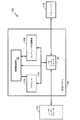
図1を参照すると、一態様では、ワイヤレス通信システム10が、RLC層エンティティにおいてUEおよび少なくとも1つのネットワークエンティティの同期を容易にするように構成される。ワイヤレス通信システム10は、限定はしないが、第1のネットワークエンティティ12および/または第2のネットワークエンティティ14を含む、1つまたは複数のネットワークエンティティを介して1つまたは複数のネットワーク(たとえば、ネットワーク16)とワイヤレス通信することができる少なくとも1つのUE11を含む。たとえば、UE11は、第1のネットワークエンティティ12および第2のネットワークエンティティ14の一方または両方に含まれているか、または配置されている1つまたは複数のセルと通信することができる。一態様では、第1のネットワークエンティティ12は代替的に、UE11が通信セッション(たとえば、RRC接続状態)を維持する第1のセルと呼ばれることがある。別の態様では、第2のネットワークエンティティ14は代替的に、UE11が通信セッション(たとえば、RRC接続状態)を維持する第2のセルと呼ばれることがある。
Referring to FIG. 1, in one aspect, a
さらにUE11は、第1のネットワークエンティティ12および/または第2のネットワークエンティティ14を介してネットワーク16と通信することができる。たとえば、一態様では、第1のネットワークエンティティ12および第2のネットワークエンティティ14は、それぞれ1つまたは複数の通信チャネル18および/または20を介して1つまたは複数の信号(たとえば、パケット/プロトコルデータユニット(PDU))を、それぞれ、UE11へ送信する/UE11から受信するように構成されてよい。たとえば、1つまたは複数の信号は、第1のネットワークエンティティ12および第2のネットワークエンティティ14の一方または両方から送信される第1のステータスPDU32および第2のステータスPDU34であってよい。
Furthermore, the
いくつかの態様では、第1のステータスPDU32および第2のステータスPDU34は、RLCウィンドウに前のすべてのPDU(たとえば、UE11によるネットワークエンティティへの送信されたPDU)の成功(たとえば、ACK)および/または失敗(たとえば、NACK)に関する情報を含んでよい。ACKは、送信された1つまたは複数のPDUを受信したことの確認応答または確認を示すまたは表すことができる。一方では、否定応答(NACK)は、少なくとも1つの送信されたPDUが受信されなかったことを示すまたは表すことができる。さらに、各通信チャネル(たとえば、1つまたは複数の通信チャネル18および/または20)に対する物理チャネル(たとえば、周波数および/またはプライマリスクランブリングコード(PSC)組合せ)は異なる可能性がある。したがって、UE11は、どの通信チャネル(たとえば、通信チャネル18および/または20)、ならびに結果としてどのネットワークエンティティ(たとえば、第1のネットワークエンティティ12および/または第2のネットワークエンティティ14)から、各ステータスPDUが受信されるかを決定するように構成されてよい。
In some aspects, the first status PDU 32 and the second status PDU 34 are the success (e.g., ACK) and / or success of all previous PDUs (e.g., PDUs sent to the network entity by the UE 11) in the RLC window. Or it may include information about failure (eg, NACK). The ACK may indicate or represent an acknowledgment or confirmation that the transmitted one or more PDUs have been received. On the other hand, a negative acknowledgment (NACK) may indicate or indicate that at least one transmitted PDU was not received. Further, the physical channel (eg, frequency and / or primary scrambling code (PSC) combination) for each communication channel (eg, one or
そのような態様では、PSCは、システムおよびセル固有のブロードキャスト制御チャネル(BCH)情報を取得するために使用される一次共通制御物理チャネル(P-CCPCH:Primary Common Control Physical Channel)を検出するのに役立つことができる。また、ステータスPDUは、送信側RLCエンティティ(たとえば、UE11)に、RLC AM(確認応答モード)PDUが第1のネットワークエンティティ12または第2のネットワークエンティティ14で受信されたという確認応答情報を知らせるために送信されてよい。たとえば、情報に基づいてUE11は、否定応答PDUを再送信すること、またはその送信ウィンドウを前に進めることを決定してよい。
In such aspects, the PSC detects the primary common control physical channel (P-CCPCH) used to obtain system and cell-specific broadcast control channel (BCH) information. Can be helpful. The status PDU also informs the transmitting RLC entity (e.g., UE11) of acknowledgment information that the RLC AM (acknowledgment mode) PDU has been received by the
本態様によれば、UE11は、同期構成要素30を含んでよく、同期構成要素30は、限定はしないが、ワイヤレス通信システム10におけるRLC層エンティティなどのプロトコル層エンティティにおいて、UE11および少なくとも1つのネットワークエンティティ(たとえば、第1のネットワークエンティティ12および/または第2のネットワークエンティティ14)を同期するように構成されてよい。詳細には、一態様では、UE11の同期構成要素30は、通信構成要素40を介して第1のステータスPDU32を受信するように構成されてよい。いくつかの態様では、第1のステータスPDU32は、最新の誤っていないステータスPDUであってよい。さらに、同期構成要素30は、通信構成要素40を介して第2のステータスPDU34を受信するように構成されてよい。そのような態様では、第2のステータスPDU34は、第1のステータスPDU32を受信することに続いて受信されてよい。いくつかの事例では、第2のステータスPDU34は、第1のステータスPDU32を受信した後に受信される任意のPDUであってよい。
In accordance with this aspect,
したがって、同期構成要素30は、たとえば第1のステータスPDU32に基づいて第2のステータスPDU34が誤ったシーケンス番号を含んでいることを識別するように構成することができる識別構成要素36を含んでよい。誤ったPDU(たとえば、誤ったステータスPDU)は、誤ったシーケンス番号を搬送するPDUであることがある。詳細には、誤ったシーケンス番号を含んだステータスPDUは、NACKされた少なくとも1つのAMD PDUのシーケンス番号が、間隔VT(A)<=シーケンス番号<VT(S)外であるリスト、ビットマップ、または相対リスト(RLIST:Relative List)スーパーフィールド(SUFI:Super Field)を含むステータスPDUであってよく、ただしVT(A)は確認状態変数とすることができ、VT(S)は送信状態変数とすることができる。また、誤ったシーケンス番号を含んだステータスPDUは、最後のシーケンス番号(LSN)が間隔VT(A)<=LSN<VT(S)外であるACK SUFIとすることができる。
Accordingly, the
一態様では、第2のステータスPDU34が誤ったSNを含むことを識別するために、識別構成要素36は、第1のステータスPDU32のSNおよび第2のステータスPDU34のSNを識別するように構成されてよい。識別構成要素36は、第2のステータスPDU34のSNがSN間隔範囲外であると決定するようにさらに構成されてよい。言い換えれば、識別構成要素36は、第2のステータスPDU34のSNが、SN間隔範囲の最小値よりも小さい(もしくはこれに等しい)、またはSN間隔範囲の最大値よりも大きい(もしくはこれに等しい)かどうかを決定するように構成されてよい。いくつかの態様では、SN間隔範囲は、第1のステータスPDU32のSNに基づいて決定されてよい。
In one aspect, to identify that the second status PDU 34 includes an incorrect SN, the
さらに、同期構成要素30は、RLCリセット決定構成要素38を含んでよく、RLCリセット決定構成要素38は、第1のステータスPDU32および第2のステータスPDU34が同じネットワークエンティティ(たとえば、第1のネットワークエンティティ12)から送信されるかどうかを決定するように構成されてよい。さらに、RLCリセット決定構成要素38は、第1のステータスPDU32および第2のステータスPDU34が同じネットワークエンティティ(たとえば、第1のネットワークエンティティ12)から送信されると決定することに少なくとも部分的に基づいて、RLCリセットを実行するように構成されてよい。いくつかの態様では、第1のステータスPDU32および第2のステータスPDU34が同じネットワークエンティティから(たとえば、第1のネットワークエンティティ12または第2のネットワークエンティティ14のいずれかから)送信されると決定することは、第1のステータスPDU32および第2のステータスPDU34から抽出されたまたは取得された情報に少なくとも部分的に基づいてよい。RLCリセットを実行することにより、UE11内のRLCエンティティ(たとえば、図7のRLCサブレイヤ411)およびネットワークがピアRLCエンティティを同期して運ぶようにすることができる。
Further, the
その上、RLCリセット決定構成要素38は、第1のステータスPDU32が第1のネットワークエンティティ12から送信され、第2のステータスPDU34が第2のネットワークエンティティ14から送信されると決定するように構成されてよい。加えて、RLCリセット決定構成要素38は、第1のネットワークエンティティ12および第2のネットワークエンティティ14が同期していると決定し、第1のネットワークエンティティ12および第2のネットワークエンティティ14が同期していると決定することに応答してRLCリセットを実行するように構成されてよい。いくつかの態様では、同期構成要素30は、第1のネットワークエンティティ12および第2のネットワークエンティティ14が同期していないと決定することに応答してRLCリセットを実行しないように構成されてよい。RLCリセット決定構成要素38は、第1のステータスPDU32および第2のステータスPDU34の内容および/またはタイミング情報(たとえば、到着時間)に少なくとも部分的に基づいて、第1のネットワークエンティティ12および第2のネットワークエンティティ14が同期外れであるまたは同期していないときを検出または識別するようにさらに構成されてよい。
In addition, the RLC reset determination component 38 is configured to determine that the first status PDU 32 is transmitted from the
一態様では、第1のネットワークエンティティ12と第2のネットワークエンティティ14の両方が、それぞれ同期している場合があり、UE11が同期を認識している場合、UE11は第1のネットワークエンティティ12および/または第2のネットワークエンティティ14のいずれかから誤ったステータスPDUを受信するとき、どちらのネットワークエンティティで前の誤っていないまたは誤ったPDUが受信されるかにかかわらず、RLCリセットを行ってよい。したがって、この状況は、非マルチフロー構成で動作するUE11と同様であってよい。
In one aspect, both the
さらに、代替的または追加の態様では、UE11は、通信構成要素40を含んでよく、通信構成要素40はUE11が、1つまたは複数の無線アクセス技術(RAT)によりまたはこれを使用して1つまたは複数の通信チャネル18を介した第1のネットワークエンティティ12、ならびに1つまたは複数のRATによりまたはこれを使用して1つまたは複数の通信チャネル20を介した第2のネットワークエンティティ14のうちの、一方または両方と通信することを容易にする、または別の様態で可能にするように構成されてよい。そのような態様では、1つまたは複数の通信チャネル18および20は、それぞれUE11と第1のネットワークエンティティ12および/または第2のネットワークエンティティ14との間でアップリンクとダウンリンクの両方で通信を可能にすることができる。
Further, in an alternative or additional aspect,
いくつかの態様では、通信構成要素40は、第1のネットワークエンティティ12および第2のネットワークエンティティ14の一方または両方からステータスPDU(たとえば、第1のステータスPDU32および第2のステータスPDU34)を受信するように構成されてよい。また、通信構成要素40は、UE11の構成要素および/または同期構成要素30間の通信を可能にするためのバスまたは他のリンクを含んでよい。一例では、通信構成要素40の態様は、UE11において送信機、受信機、および/または送受信機(たとえば、送受信機110、図4と同じまたは同様)によって実行または実装されてよい。
In some aspects, the
UE11は、モバイル装置を含むことができる、および/または本開示を通じてそのように呼ばれることがある。そのようなモバイル装置またはUE11は、当業者によって、移動局、加入者局、モバイルユニット、加入者ユニット、ワイヤレスユニット、リモートユニット、モバイルデバイス、ワイヤレスデバイス、ワイヤレス通信デバイス、リモートデバイス、モバイル加入者局、アクセス端末、モバイル端末、ワイヤレス端末、リモート端末、ハンドセット、端末、ユーザエージェント、モバイルクライアント、クライアント、モノのインターネット用のデバイス、または何らかの他の適切な用語で呼ばれることもある。
また、限定はしないが、ワイヤレス通信システム10の、それぞれ第1および第2のネットワークエンティティ12および/または14を含む1つまたは複数のワイヤレスノードは、基地局またはノードBを含むアクセスポイント、リレー、ピアツーピアデバイス、認証、許可、課金(AAA)サーバ、モバイル交換センター(MSC)、無線ネットワークコントローラ(RNC)などの任意のタイプのネットワーク構成要素のうちの1つまたは複数を含むことができる。さらなる態様では、ワイヤレス通信システム10の1つまたは複数のワイヤレスサービングノードは、限定はしないが、スモールセル、フェムトセル、ピコセル、マイクロセル、またはマクロ基地局と比較して、比較的小さい送信電力もしくは比較的小さいカバレージエリアを有する他の任意の基地局など、1つまたは複数の小規模セル基地局を含むことができる。
Also, but not limited to, one or more wireless nodes of the
図2および図3を参照すると、本発明の方法については、説明を簡単にするために、一連の行為として図示し説明している。しかし、いくつかの行為は、1つまたは複数の態様に従って、本明細書において図示し説明する順序とは異なる順序で行われ、および/または本明細書において図示し説明する以外の行為と同時に行われ得るので、本明細書の方法(さらにその方法に関連するさらなる方法)が、行為の順序によって制限されることがないことを理解し、諒解されたい。たとえば、方法は、代わりに、状態図などにおいて、一連の相互に関係する状態またはイベントとして表され得ることを諒解されたい。その上、本明細書で説明された1つまたは複数の特徴に従って方法を実施するために、示されたすべての動作が必要とされるとは限らない。 Referring to FIGS. 2 and 3, the method of the present invention is illustrated and described as a series of actions for ease of explanation. However, some acts may be performed in a different order than shown and described herein and / or concurrently with acts other than those shown and described herein, according to one or more aspects. It should be understood and understood that the methods herein (and further methods associated therewith) are not limited by the order of actions. For example, it should be appreciated that a method may alternatively be represented as a series of interrelated states or events, such as in a state diagram. Moreover, not all illustrated acts may be required to implement a methodology in accordance with one or more features described herein.
図2を参照すると、一動作態様において、UE11(図1)のようなUEは、RLC層でUEおよびネットワークエンティティを同期するための方法50の一態様を実行することができる。
Referring to FIG. 2, in one operational aspect, a UE such as UE 11 (FIG. 1) may perform one aspect of a
一態様では、ブロック52において方法50は、第1のステータスPDUを受信するステップを含むことができ、第1のステータスPDUは、最新の誤っていないステータスPDUである。たとえば、本明細書で説明するように、UE11(図1)は、第1のステータスPDU32(図1)を受信するために同期構成要素30(図1)および/または通信構成要素40(図1)を実行することができ、第1のステータスPDU32(図1)は、最新の誤っていないステータスPDUである。いくつかの態様では、第1のステータスPDU32(図1)は、第1のネットワークエンティティ12(図1)から通信チャネル18(図1)を介して受信される場合がある。
In an aspect, the
ブロック54において方法50は、第2のステータスPDUを受信するステップを含んでよく、第2のステータスPDUは、第1のステータスPDUを受信するステップに続いて受信される。たとえば、本明細書で説明するように、UE11(図1)は、第2のステータスPDU34(図1)を受信するために同期構成要素30(図1)および/または通信構成要素40(図1)を実行することができ、第2のステータスPDU34(図1)は、第1のステータスPDU32(図1)を受信するステップに続いて受信される。いくつかの事例では、第2のステータスPDU34(図1)は、第1のネットワークエンティティ12(図1)から通信チャネル18(図1)を介して受信される場合がある。他の事例では、第2のステータスPDU34(図1)は、第2のネットワークエンティティ14(図1)から通信チャネル20(図1)を介して受信される場合がある。
In
さらに、ブロック56において方法50は、第1のステータスPDUに少なくとも部分的に基づいて、第2のステータスPDUが誤ったSNを含むことを識別するステップを含むことができる。たとえば、本明細書で説明するように、UE11(図1)および/または同期構成要素30は、第1のステータスPDU32(図1)に少なくとも部分的に基づいて第2のステータスPDU34(図1)が誤ったSNを含むことを識別するために識別構成要素36(図1)を実行することができる。いくつかの事例では、第1のステータスPDU32(図1)および第2のステータスPDU34(図1)が同じネットワークエンティティから(たとえば、第1のネットワークエンティティ12(図1)または第2のネットワークエンティティ14(図1)のいずれかから)送信されると決定することは、第1のステータスPDU32(図1)および第2のステータスPDU34(図1)から抽出されたまたは取得された情報に少なくとも部分的に基づく。
Further, at
その後、ブロック58において方法50は、第2のステータスPDUが誤ったSNを含むと決定することに少なくとも部分的に基づいて、RLCリセットを実行するかどうかを決定するステップを含むことができる。たとえば、本明細書で説明するように、UE11(図1)および/または同期構成要素30(図1)は、第2のステータスPDU34(図1)が誤ったSNを含むと決定することに少なくとも部分的に基づいてRLCリセットを実行するかどうかを決定するためにRLCリセット決定構成要素38(図1)を実行することができる。
Thereafter, at
図3を参照すると、追加のおよび/または代替の動作態様において、UE11(図1)のようなUEは、RLC層においてUEおよび1つまたは複数のネットワークエンティティを同期するための方法60の一態様を実行することができる。方法60を形成する各ブロックに関して本明細書で説明する態様を実行するために、同期構成要素30(図1)の様々な構成要素および/またはサブ構成要素のうちの任意の1つまたは複数が実行されてよいことは理解されたい。
Referring to FIG. 3, in additional and / or alternative operational aspects, a UE, such as UE 11 (FIG. 1), may implement an aspect of a
一態様では、ブロック62において方法60は任意で、NodeB間のマルチフロー動作が構成されていることを決定するステップを含むことができる。たとえば、本明細書で説明するように、UE11(図1)は、NodeB間のマルチフロー動作が構成されていることを決定するために同期構成要素30を実行することができる。いくつかの事例では、第1のステータスPDU32を受信するステップは、UE(たとえば、UE11)がNodeB間のマルチフロー動作用に構成されているとき、第1のステータスPDU32を受信するステップを含み、第2のステータスPDU34を受信するステップは、UE(たとえば、UE11)がNodeB間のマルチフロー動作用に構成されているとき、第2のステータスPDU34を受信するステップを含む。
In one aspect, the
ブロック64において方法60は、第1のステータスPDUを受信するステップを含むことができる。たとえば、本明細書で説明するように、UE11(図1)は、第1のステータスPDU32を受信するために、同期構成要素30および/または通信構成要素40(図1)を実行することができる。いくつかの事例では、第1のステータスPDU32は、第1のネットワークエンティティ12から通信チャネル18を介して受信される場合がある。一態様では、同期構成要素30は、第1のステータスPDU32を受信することができ、第1のステータスPDU32は、最新の誤っていないステータスPDUである。
At
ブロック66において方法60は、第2のステータスPDUを受信するステップを含むことができる。たとえば、本明細書で説明するように、UE11(図1)は、第2のステータスPDU34を受信するために、同期構成要素30および/または通信構成要素40を実行することができる。いくつかの事例では、第2のステータスPDU34は、第1のネットワークエンティティ12から通信チャネル18を介して受信される場合がある。他の事例では、第2のステータスPDU34は、第2のネットワークエンティティ14から通信チャネル20を介して受信される場合がある。その上、第2のステータスPDU34は、第1のステータスPDU32を受信することに続いてUE11および/または同期構成要素30によって受信されてよい。一態様では、同期構成要素30は、第1のステータスPDU32に少なくとも部分的に基づいて、第2のステータスPDU34が誤ったSNを含むことを識別することができる。
At
さらに、ブロック68において方法60は、第1のステータスPDUおよび第2のステータスPDUが、同じネットワークエンティティから送信されるかどうかを決定するステップを含むことができる。たとえば、本明細書で説明するように、UE11(図1)および/または同期構成要素30は、第1のステータスPDU32および第2のステータスPDU34が同じネットワークエンティティから(たとえば、第1のネットワークエンティティ12または第2のネットワークエンティティ14のいずれかから)送信されるかどうかを決定するためにRLCリセット決定構成要素38を実行することができる。第1のステータスPDU32および第2のステータスPDU34が同じネットワークエンティティから送信されると決定される場合、方法60は、ブロック70に進むことができる。
Further, at
ブロック70において方法60は、RLCリセットを実行するステップを含むことができる。たとえば、本明細書で説明するように、UE11(図1)は、第1のステータスPDU32および第2のステータスPDU34が同じネットワークエンティティから(たとえば、第1のネットワークエンティティ12から)送信されると決定することに少なくとも部分的に基づいてRLCリセットを実行するために、同期構成要素30および/またはRLCリセット決定構成要素38を実行することができる。
At
その上、第1のステータスPDU32および第2のステータスPDU34が異なるネットワークエンティティから(たとえば、第1のネットワークエンティティ12および第2のネットワークエンティティ14から)送信されると決定される場合、方法60は、ブロック72に進むことができる。ブロック72において方法60は、第1のネットワークエンティティおよび第2のネットワークエンティティが同期しているかどうかを決定するステップを含むことができる。たとえば、本明細書で説明するように、UE11(図1)および/または同期構成要素30は、第1のネットワークエンティティ12および第2のネットワークエンティティ14が同期しているかどうかを決定するために、RLCリセット決定構成要素38を実行することができる。第1のネットワークエンティティ12および第2のネットワークエンティティ14が同期していると決定される場合、方法60は、ブロック70に進むことができ、UE11(図1)は、RLCリセットを実行するために同期構成要素30を実行することができる。しかしながら、第1のネットワークエンティティ12および第2のネットワークエンティティ14が同期していないと決定される場合、方法60は、ブロック74に進むことができる。
Moreover, if it is determined that the first status PDU 32 and the second status PDU 34 are transmitted from different network entities (e.g., from the
ブロック74において方法60は、RLCリセットを実行しないことを含むことができる。たとえば、本明細書で説明するように、UE11(図1)は、RLCリセットを実行しないように、同期構成要素30を実行することができる。
In
図4は、処理システム114を使用する装置100のハードウェア実装形態の一例を示すブロック図であり、装置100は、UE11(図1)であってよく、またはUE11内に含まれてもよく、装置100は、本明細書で説明する動作を実行するための同期構成要素30を備えて構成される。たとえば、同期構成要素30は、プロセッサ104内の1つもしくは複数のプロセッサモジュールとして、またはコンピュータ可読媒体106として記憶され、プロセッサ104によって実行されるコードもしくは命令として、または両方の何らかの組合せとして実装されてよい。この例では、処理システム114は、バス102によって全般的に表されるバスアーキテクチャを用いて実装され得る。バス102は、処理システム114の具体的な用途および全体的な設計制約に応じて、任意の数の相互接続するバスおよびブリッジを含み得る。バス102は、プロセッサ104によって全般的に表される1つまたは複数のプロセッサ、コンピュータ可読媒体106によって全般的に表されるコンピュータ可読媒体を含む、様々な回路を一緒につなぐ。
FIG. 4 is a block diagram illustrating an example of a hardware implementation of an
バス102は、タイミングソース、周辺機器、電圧調整器、および電力管理回路など、様々な他の回路をリンクさせることもでき、これらの回路は当技術分野でよく知られており、したがって、これ以上は説明しない。バスインターフェース108は、バス102とトランシーバ110との間にインターフェースを提供する。トランシーバ110は、送信媒体上の様々な他の装置と通信するための手段を提供する。また、装置の性質に応じて、ユーザインターフェース112(たとえば、キーパッド、ディスプレイ、スピーカー、マイクロフォン、ジョイスティックなど)が設けられてもよい。
プロセッサ104は、バス102の管理、およびコンピュータ可読媒体106上に記憶されたソフトウェアの実行を含む全般的な処理を受け持つ。ソフトウェアは、プロセッサ104によって実行されると、任意の特定の装置の以下で説明される様々な機能を処理システム114に実行させる。コンピュータ可読媒体106は、ソフトウェアを実行するときにプロセッサ104によって操作されるデータを記憶するために使用されてもよい。同期構成要素30は、プロセッサ104および/またはコンピュータ可読媒体106の一部であってよい。
The
本開示全体にわたって提示される様々な概念は、広範な電気通信システム、ネットワークアーキテクチャ、および通信規格にわたって実装され得る。 Various concepts presented throughout this disclosure may be implemented across a wide range of telecommunications systems, network architectures, and communication standards.
限定されるものではないが、例として、図5に示す本開示の態様は、W-CDMAエアインターフェースを採用するUMTSシステム200に関して提示されている。この事例では、ユーザ機器210は、図1のUE11と同じまたは同様であってよく、本明細書で説明するように同期構成要素30を含んでよい。UMTSネットワークは、コアネットワーク(CN)204、UMTS地上無線アクセスネットワーク(UTRAN)202、およびユーザ機器(UE)210という、3つの対話する領域を含む。この例では、UTRAN202は、電話、ビデオ、データ、メッセージング、ブロードキャスト、および/または他のサービスを含む様々なワイヤレスサービスを提供する。UTRAN202は、無線ネットワークコントローラ(RNC)206などのそれぞれのRNCによって各々制御される、無線ネットワークサブシステム(RNS)207などの複数のRNSを含み得る。ここで、UTRAN202は、本明細書で説明するRNC206およびRNS207に加えて、任意の数のRNC206およびRNS207を含むことができる。RNC206は、とりわけ、RNS207内の無線リソースの割り当て、再構成、および解放を担う装置である。RNC206は、任意の適切なトランスポートネットワークを使用する、直接の物理接続、仮想ネットワークなど様々なタイプのインターフェースを介して、UTRAN202中の他のRNC(図示せず)に相互接続され得る。
By way of example, and not limitation, the aspect of the present disclosure shown in FIG. 5 is presented with respect to a
UE210とNodeB208との間の通信は、物理(PHY)層および媒体アクセス制御(MAC)層を含むものと見なされ得る。さらに、それぞれのNodeB208によるUE210とRNC206との間の通信は、無線リソース制御(RRC)層を含むものと見なされ得る。本明細書では、PHY層は、層1と見なされ、MAC層は、層2と見なされ、RRC層は、層3と見なされ得る。情報は、参照により本明細書に組み込まれる、RRC Protocol Specification、3GPP TS 25.331 v9.1.0に述べられている用語を、以下、利用する。
Communication between
RNS207によってカバーされる地理的領域は、いくつかのセルに分けることができ、無線トランシーバ装置が各セルにサービスする。無線トランシーバ装置は、通常、UMTS適用例ではNodeBと呼ばれるが、当業者によって、基地局(BS)、送受信基地局(BTS)、無線基地局、無線トランシーバ、トランシーバ機能、基本サービスセット(BSS)、拡張サービスセット(ESS)、アクセスポイント(AP)、または何らかの他の適切な用語で呼ばれることもある。明快にするために、各RNS207に3つのNodeB208が示されているが、RNS207は、任意の数のワイヤレスNodeBを含んでもよい。NodeB208は、ワイヤレスアクセスポイントを任意の数のモバイル装置のためのCN204に提供する。モバイル装置の例には、携帯電話、スマートフォン、セッション開始プロトコル(SIP)電話、ラップトップ、ノートブック、ネットブック、スマートブック、携帯情報端末(PDA)、衛星ラジオ、全地球測位システム(GPS)デバイス、マルチメディアデバイス、ビデオ装置、デジタルオーディオプレーヤ(たとえば、MP3プレーヤなど)、カメラ、ゲーム機、または任意の他の類似の機能デバイスなどがある。
The geographical area covered by the
モバイル装置は、通常、UMTS適用例ではUEと呼ばれるが、当業者によって、移動局、加入者局、モバイルユニット、加入者ユニット、ワイヤレスユニット、遠隔ユニット、モバイルデバイス、ワイヤレスデバイス、ワイヤレス通信デバイス、遠隔デバイス、モバイル加入者局、アクセス端末、モバイル端末、ワイヤレス端末、遠隔端末、ハンドセット、端末、ユーザエージェント、モバイルクライアント、クライアント、またはいくつかの他の適切な用語で呼ばれることもある。UMTSシステムでは、UE210は、ネットワークへのユーザの加入情報を含む汎用加入者識別モジュール(USIM)211をさらに含み得る。説明のために、1つのUE210がいくつかのNodeB208と通信しているように示される。順方向リンクとも呼ばれるダウンリンク(DL)は、NodeB208からUE210への通信リンクを指し、逆方向リンクとも呼ばれるアップリンク(UL)は、UE210からNodeB208への通信リンクを指す。
A mobile device is commonly referred to as a UE in a UMTS application, but by a person skilled in the art, a mobile station, a subscriber station, a mobile unit, a subscriber unit, a wireless unit, a remote unit, a mobile device, a wireless device, a wireless communication device, a remote It may also be referred to as device, mobile subscriber station, access terminal, mobile terminal, wireless terminal, remote terminal, handset, terminal, user agent, mobile client, client, or some other appropriate terminology. In the UMTS system, the
CN204は、UTRAN202など1つまたは複数のアクセスネットワークとインターフェースをとる。図示のように、CN204は、GSM(登録商標)コアネットワークである。しかしながら、当業者が認識するように、GSM(登録商標)ネットワーク以外のタイプのCNへのアクセスをUEに提供するために、本開示全体にわたって提示される様々な概念を、RANまたは他の適切なアクセスネットワークにおいて実装することができる。
CN204は、回線交換(CS)領域およびパケット交換(PS)領域を含む。回線交換要素のいくつかは、モバイルサービス交換センター(MSC)、ビジターロケーションレジスタ(VLR)、およびゲートウェイMSCである。パケット交換要素は、サービングGPRSサポートノード(SGSN)、およびゲートウェイGPRSサポートノード(GGSN)を含む。EIR、HLR、VLR、およびAuCのようないくつかのネットワーク要素は、回線交換領域とパケット交換領域の両方によって共有され得る。図示の例では、CN204は、MSC212およびGMSC214によって回線交換サービスをサポートする。いくつかの用途では、GMSC214は、メディアゲートウェイ(MGW)とも呼ばれ得る。
The
RNC206のような1つまたは複数のRNCが、MSC212に接続され得る。MSC212は、呼設定、呼ルーティング、およびUEモビリティ機能を制御する装置である。MSC212は、UEがMSC212のカバレッジエリア内にある間に加入者関連の情報を格納するVLRも含む。GMSC214は、UEが回線交換ネットワーク216にアクセスするためのゲートウェイを、MSC212を通じて提供する。GMSC214は、特定のユーザが加入したサービスの詳細を反映するデータのような加入者データを格納するホームロケーションレジスタ(HLR)215を含む。HLRは、加入者に固有の認証データを格納する認証センター(AuC)とも関連付けられている。特定のUEについて、呼が受信されると、GMSC214は、UEの位置を判断するためにHLR215に問い合わせ、その位置でサービスする特定のMSCに呼を転送する。
One or more RNCs such as
CN204はまた、サービングGPRSサポートノード(SGSN)218およびゲートウェイGPRSサポートノード(GGSN)220によって、パケットデータサービスをサポートする。汎用パケット無線サービスを表すGPRSは、標準の回線交換データサービスで可能なものよりも速い速度でパケットデータサービスを提供するよう設計されている。GGSN220は、パケットベースネットワーク222へのUTRAN202の接続を提供する。パケットベースネットワーク222は、インターネット、プライベートデータネットワーク、または何らかの他の適切なパケットベースネットワークでもよい。GGSN220の一次機能は、UE210にパケットベースネットワーク接続を提供することである。データパケットは、MSC212が回線交換領域において実行するのと同じ機能をパケットベース領域において主に実行するSGSN218を介して、GGSN220とUE210との間で転送され得る。
UMTSのエアインターフェースは、スペクトラム拡散直接シーケンス符号分割多元接続(DS-CDMA)システムを利用してよい。スペクトラム拡散DS-CDMAは、チップと呼ばれる一連の疑似ランダムビットとの乗算によって、ユーザデータを拡散させる。UMTSの「広帯域」W-CDMAエアインターフェースは、そのような直接シーケンススペクトラム拡散技術に基づいており、さらに周波数分割複信(FDD)を必要とする。FDDは、NodeB208とUE210との間のULおよびDLに異なるキャリア周波数を使用する。DS-CDMAを利用し、時分割複信(TDD)を使用するUMTSの別のエアインターフェースは、TD-SCDMAエアインターフェースである。本明細書で説明される様々な例は、W-CDMAエアインターフェースを指し得るが、基礎をなす原理はTD-SCDMAエアインターフェースに等しく適用可能であり得ることを、当業者は理解するだろう。
The UMTS air interface may utilize a spread spectrum direct sequence code division multiple access (DS-CDMA) system. Spread spectrum DS-CDMA spreads user data by multiplication with a series of pseudo-random bits called chips. The UMTS “broadband” W-CDMA air interface is based on such direct sequence spread spectrum technology and further requires frequency division duplex (FDD). FDD uses different carrier frequencies for UL and DL between
HSPAエアインターフェースは、スループットの向上および遅延の低減を支援する、3G/W-CDMAエアインターフェースに対する一連の拡張を含む。前のリリースに対する他の修正には、HSPAが、ハイブリッド自動再送要求(HARQ)、チャネル送信の共有、ならびに適応変調および適応符号化を利用する。HSPAを定義する規格は、HSDPA(高速ダウンリンクパケットアクセス)およびHSUPA(高速アップリンクパケットアクセス、拡張アップリンクまたはEULとも呼ばれる)を含む。 The HSPA air interface includes a series of extensions to the 3G / W-CDMA air interface that help improve throughput and reduce latency. Other modifications to previous releases utilize HSPA hybrid automatic repeat request (HARQ), channel transmission sharing, and adaptive modulation and coding. Standards that define HSPA include HSDPA (High Speed Downlink Packet Access) and HSUPA (High Speed Uplink Packet Access, also called Enhanced Uplink or EUL).
HSDPAは、高速ダウンリンク共有チャネル(HS-DSCH)を、トランスポートチャネルとして利用する。HS-DSCHは、高速物理ダウンリンク共有チャネル(HS-PDSCH)、高速共有制御チャネル(HS-SCCH)、および高速専用物理制御チャネル(HS-DPCCH)という、3つの物理チャネルによって実装される。 HSDPA uses a high-speed downlink shared channel (HS-DSCH) as a transport channel. HS-DSCH is implemented by three physical channels: a high-speed physical downlink shared channel (HS-PDSCH), a high-speed shared control channel (HS-SCCH), and a high-speed dedicated physical control channel (HS-DPCCH).
これらの物理チャネルの中でも、HS-DPCCHは、対応するパケット送信の復号が成功したかどうかを示すための、HARQ ACK/NACKシグナリングをアップリンクで搬送する。つまり、ダウンリンクに関して、UE210は、ダウンリンク上のパケットを正常に復号したかどうかを示すために、HS-DPCCHを通じてフィードバックをノードB208に与える。
Among these physical channels, the HS-DPCCH carries HARQ ACK / NACK signaling on the uplink to indicate whether the corresponding packet transmission has been successfully decoded. That is, for the downlink, the
HS-DPCCHはさらに、変調方式と符号化方式の選択、およびプリコーディングの重みの選択に関して、ノードB208が正しい決定を行うのを支援するための、UE210からのフィードバックシグナリングを含み、このフィードバックシグナリングはCQIおよびPCIを含む。
The HS-DPCCH further includes feedback signaling from the
"HSPA Evolved"またはHSPA+は、MIMOおよび64-QAMを含むHSPA規格の進化形であり、スループットの増大およびパフォーマンスの向上を可能にする。つまり、本開示のある態様では、ノードB208および/またはUE210は、MIMO技術をサポートする複数のアンテナを有し得る。MIMO技術の使用により、ノードB208は空間領域を活用して、空間多重化、ビームフォーミング、および送信ダイバーシティをサポートすることができる。
“HSPA Evolved” or HSPA + is an evolution of the HSPA standard, including MIMO and 64-QAM, allowing increased throughput and improved performance. That is, in certain aspects of the present disclosure,
多入力多出力(MIMO)は、マルチアンテナ技術、すなわち複数の送信アンテナ(チャネルへの複数の入力)および複数の受信アンテナ(チャネルからの複数の出力)を指す際に一般に使用される用語である。MIMOシステムは一般にデータ伝送パフォーマンスを高め、ダイバーシティ利得がマルチパスフェージングを低減させて伝送品質を高めること、および空間多重化利得がデータスループットを向上させることを可能にする。 Multiple Input Multiple Output (MIMO) is a term commonly used to refer to multi-antenna technology, i.e. multiple transmit antennas (multiple inputs to a channel) and multiple receive antennas (multiple outputs from a channel). . MIMO systems generally increase data transmission performance, allowing diversity gain to reduce multipath fading and increase transmission quality, and spatial multiplexing gain to improve data throughput.
空間多重化を使用して、同じ周波数で同時に様々なデータストリームを送信することができる。データストリームを単一のUE210に送信してデータレートを上げること、または複数のUE210に送信して全体的なシステム容量を拡大することができる。これは、各データストリームを空間的にプリコーディングし、次いで空間的にプリコーディングされた各ストリームをダウンリンクで異なる送信アンテナを介して送信することによって達成される。空間的にプリコーディングされたデータストリームは、様々な空間シグネチャを伴いUE210に到着し、これによりUE210の各々は、当該UE210に向けられた1つまたは複数のデータストリームを回復することができる。アップリンク上では、各UE210は、1つまたは複数の空間的にプリコーディングされたデータストリームを送信することができ、これによりノードB208は空間的にプリコーディングされた各データストリームのソースを識別することができる。
Spatial multiplexing can be used to transmit different data streams simultaneously on the same frequency. Data streams can be sent to a
空間多重化は、チャネル状態が良好なときに使用できる。チャネル状態がさほど好ましくないときは、ビームフォーミングを使用して送信エネルギーを1つもしくは複数の方向に集中させること、またはチャネルの特性に基づいて送信を改善することができる。これは、複数のアンテナを介して送信するデータストリームを空間的にプリコーディングすることによって達成できる。セルの端において良好なカバレージを達成するために、シングルストリームビームフォーミング伝送を送信ダイバーシティと組み合わせて使用できる。 Spatial multiplexing can be used when channel conditions are good. When channel conditions are less favorable, beamforming can be used to concentrate transmission energy in one or more directions, or to improve transmission based on channel characteristics. This can be achieved by spatially precoding the data stream to be transmitted over multiple antennas. Single stream beamforming transmission can be used in combination with transmit diversity to achieve good coverage at the cell edge.
一般に、n個の送信アンテナを利用するMIMOシステムの場合、同じチャネル化コードを利用して同じキャリアでn個のトランスポートブロックが同時に送信され得る。n個の送信アンテナで送られる異なるトランスポートブロックは、互いに同じまたは異なる変調方式および符号化方式を有し得ることに留意されたい。 In general, in the case of a MIMO system using n transmit antennas, n transport blocks can be transmitted simultaneously on the same carrier using the same channelization code. Note that different transport blocks sent by n transmit antennas may have the same or different modulation and coding schemes.
一方、単入力多出力(SIMO)は一般に、単一の送信アンテナ(チャネルへの単一の入力)および複数の受信アンテナ(チャネルからの複数の出力)を利用するシステムを指す。それによって、SIMOシステムでは、単一のトランスポートブロックがそれぞれのキャリアで送られ得る。 Single input multiple output (SIMO), on the other hand, generally refers to a system that utilizes a single transmit antenna (single input to the channel) and multiple receive antennas (multiple outputs from the channel). Thereby, in a SIMO system, a single transport block can be sent on each carrier.
図6を参照すると、UTRANアーキテクチャにおけるアクセスネットワーク300が示されている。多元接続ワイヤレス通信システムは、セル302、304、および306を含む複数のセルラー領域(セル)を含み、セルの各々は、1つまたは複数のセクタを含み得る。複数のセクタはアンテナのグループによって形成されてよく、各々のアンテナがセルの一部にあるUEとの通信を担う。たとえば、セル302において、アンテナグループ312、314、および316は、各々異なるセクタに対応し得る。セル304において、アンテナグループ318、320、および322は、各々異なるセクタに対応する。セル306において、アンテナグループ324、326、および328は、各々異なるセクタに対応する。セル302、304、および306は、各セル302、304、または306の1つまたは複数のセクタと通信していてもよい、いくつかのワイヤレス通信デバイス、たとえばユーザ機器またはUEを含み得る。たとえば、UE330および332は、NodeB342と通信していてもよく、UE334および336は、NodeB344と通信していてもよく、UE338および340は、NodeB346と通信していてもよい。ここで、各NodeB342、344、346は、それぞれのセル302、304、および306の中のすべてのUE330、332、334、336、338、340のために、CN204(図2参照)へのアクセスポイントを提供するように構成される。UE330、332、334、336、338、340は、同期構成要素30を含むおよび/または実行するように構成されたUE11(図1)に対応してよい。
Referring to FIG. 6, an
UE334がセル304における図示された位置からセル306に移動するとき、サービングセル変更(SCC)またはハンドオーバが生じて、UE334との通信が、ソースセルと呼ばれ得るセル304からターゲットセルと呼ばれ得るセル306に移行することがある。UE334において、それぞれのセルに対応するNodeBにおいて、無線ネットワークコントローラ206(図5)において、またはワイヤレスネットワークにおける別の適切なノードにおいて、ハンドオーバプロシージャの管理が生じ得る。たとえば、ソースセル304との呼の間、または任意の他の時間において、UE334は、ソースセル304の様々なパラメータ、ならびに、セル306、および302のような近隣セルの様々なパラメータを監視することができる。さらに、これらのパラメータの品質に応じて、UE334は、近隣セルの1つまたは複数との通信を保つことができる。この期間において、UE334は、UE334が同時に接続されるセルのリストであるアクティブセットを保持することができる(すなわち、ダウンリンク専用物理チャネルDPCHまたはフラクショナルダウンリンク専用物理チャネルF-DPCHをUE334に現在割り当てているUTRAセルが、アクティブセットを構成し得る)。
When
アクセスネットワーク300によって用いられる変調方式および多元接続方式は、導入されている特定の電気通信規格に応じて異なり得る。例として、規格は、Evolution-Data Optimized(EV-DO)またはUltra Mobile Broadband(UMB)を含み得る。EV-DOおよびUMBは、CDMA2000規格ファミリーの一部として第3世代パートナーシッププロジェクト2(3GPP2)によって公表されたエアインターフェース規格であり、CDMAを用いて移動局にブロードバンドインターネットアクセスを提供する。規格は代替的に、広帯域CDMA(W-CDMA)およびTD-SCDMAなどのCDMAの他の変形態を用いるUniversal Terrestrial Radio Access(UTRA)、TDMAを用いるGlobal System for Mobile Communications(GSM(登録商標))、ならびにOFDMAを用いるEvolved UTRA(E-UTRA)、Ultra Mobile Broadband(UMB)、IEEE 802.11(Wi-Fi)、IEEE 802.16(WiMAX)、IEEE 802.20、およびFlash-OFDMであり得る。UTRA、E-UTRA、UMTS、LTE、LTE Advanced、およびGSM(登録商標)は、3GPP団体による文書に記述されている。CDMA2000およびUMBは、3GPP2団体による文書に記述されている。実際の利用されるワイヤレス通信規格、多元接続技術は、具体的な用途およびシステム全体に課される設計制約に依存する。
The modulation scheme and multiple access scheme used by
無線プロトコルアーキテクチャは、具体的な用途に応じて様々な形態をとり得る。ここで、図7を参照してHSPAシステムの例が提示される。 The radio protocol architecture may take various forms depending on the specific application. An example of an HSPA system is now presented with reference to FIG.
図7を参照すると、例示的な無線プロトコルアーキテクチャ400は、ユーザ機器(UE)またはノードB/基地局のユーザプレーン402および制御プレーン404に関係する。たとえば、アーキテクチャ400は、同期構成要素30を含むおよび/または実行するように構成されたUE11(図1)などのUEに含まれてもよい。UEおよびノードBの無線プロトコルアーキテクチャ400は、レイヤ1 406、レイヤ2 408、およびレイヤ3 410という3つの層で示される。レイヤ1 406は最も下のレイヤであり、様々な物理層の信号処理機能を実装する。したがって、レイヤ1 406は、物理層407を含む。レイヤ2(L2レイヤ)408は、物理層407の上にあり、物理層407を通じたUEとノードBとの間のリンクを担う。レイヤ3(L3レイヤ)410は、無線リソース制御(RRC)サブレイヤ415を含む。RRCサブレイヤ415は、UEとUTRANとの間のレイヤ3の制御プレーンシグナリングを扱う。
Referring to FIG. 7, an example
ユーザプレーンでは、L2層408は、媒体アクセス制御(MAC)サブレイヤ409、無線リンク制御(RLC)サブレイヤ411、およびパケットデータコンバージェンスプロトコル(PDCP)サブレイヤ413を含み、これらはネットワーク側のノードBで終端する。示されないが、UEは、ネットワーク側のPDNゲートウェイで終端するネットワーク層(たとえばIP層)と、接続の他の端部(たとえば、遠端のUE、サーバなど)で終端するアプリケーション層とを含めて、L2層408より上にいくつかの上位層を有し得る。
In the user plane, the
PDCPサブレイヤ413は、異なる無線ベアラと論理チャネルとの間の多重化を行う。PDCPサブレイヤ413はまた、無線送信のオーバーヘッドを低減するための上位層データパケットのヘッダ圧縮、データパケットの暗号化によるセキュリティ、および、ノードB間のUEのハンドオーバのサポートを実現する。RLCサブレイヤ411は、上位層のデータパケットのセグメント化および再構築、失われたデータパケットの再送信、ならびに、ハイブリッド自動再送要求(HARQ)による順序の狂った受信を補償するためのデータパケットの再順序付けを行う。MACサブレイヤ409は、論理チャネルとトランスポートチャネルとの間の多重化を行う。MACサブレイヤ409はまた、1つのセルの中の様々な無線リソース(たとえばリソースブロック)の複数のUEへの割り当てを担う。MACサブレイヤ409はまた、HARQ動作も担う。
The
図8は、UE850と通信しているNodeB810のブロック図であり、NodeB810は、図5のNodeB208であってよく、UE850は、どちらも本明細書で説明する動作を実行するための同期構成要素30を含む、図5のUE210、または図1のUE11であってよい。ダウンリンク通信では、送信プロセッサ820は、データソース812からデータを受信し、コントローラ/プロセッサ840から制御信号を受信することができる。送信プロセッサ820は、参照信号(たとえばパイロット信号)とともに、データ信号および制御信号のための様々な信号処理機能を提供する。たとえば、送信プロセッサ820は、誤り検出のための巡回冗長検査(CRC)コード、順方向誤り訂正(FEC)を支援するための符号化およびインターリービング、様々な変調方式(たとえば、二位相偏移変調(BPSK)、四位相偏移変調(QPSK)、M-位相偏移変調(M-PSK)、M-直角位相振幅変調(M-QAM)など)に基づいた信号配列へのマッピング、直交可変拡散率(OVSF)による拡散、および、一連のシンボルを生成するためのスクランブリングコードとの乗算を、提供することができる。
FIG. 8 is a block diagram of
送信プロセッサ820のための、符号化方式、変調方式、拡散方式および/またはスクランブリング方式を決定するために、チャネルプロセッサ844からのチャネル推定が、コントローラ/プロセッサ840によって使われ得る。これらのチャネル推定は、UE850によって送信される参照信号から、またはUE850からのフィードバックから、導出され得る。送信プロセッサ820によって生成されたシンボルは、フレーム構造を作成するために、送信フレームプロセッサ830に与えられる。送信フレームプロセッサ830は、コントローラ/プロセッサ840からの情報とシンボルとを多重化することによって、このフレーム構造を作成し、一連のフレームが得られる。次いでこのフレームは送信機832に与えられ、送信機832は、アンテナ834を通じたワイヤレス媒体によるダウンリンク送信のために、増幅、フィルタリング、およびフレームのキャリア上への変調を含む、様々な信号調整機能を提供する。アンテナ834は、たとえば、ビームステアリング双方向適応アンテナアレイまたは他の同様のビーム技術を含む、1つまたは複数のアンテナを含み得る。
Channel estimation from
UE850において、受信機854は、アンテナ852を通じてダウンリンク送信を受信し、その送信を処理してキャリア上へ変調されている情報を回復する。受信機854によって回復された情報は、受信フレームプロセッサ860に与えられ、受信フレームプロセッサ860は、各フレームを解析し、フレームからの情報をチャネルプロセッサ894に提供し、データ信号、制御信号、および参照信号を受信プロセッサ870に提供する。受信プロセッサ870は次いで、NodeB810中の送信プロセッサ820によって実行される処理の逆を実行する。より具体的には、受信プロセッサ870は、シンボルを逆スクランブルおよび逆拡散し、次いで変調方式に基づいて、NodeB810によって送信された、最も可能性の高い信号配列点を求める。これらの軟判定は、チャネルプロセッサ894によって計算されるチャネル推定に基づき得る。そして軟判定は、データ信号、制御信号、および参照信号を回復するために、復号されてデインターリーブされる。そして、フレームの復号が成功したかどうか判断するために、CRCコードが確認される。次いで、復号に成功したフレームによって搬送されるデータがデータシンク872に与えられ、データシンク872は、UE850および/または様々なユーザインターフェース(たとえばディスプレイ)において実行されているアプリケーションを表す。復号に成功したフレームが搬送する制御信号は、コントローラ/プロセッサ890に与えられる。受信プロセッサ870によるフレームの復号が失敗すると、コントローラ/プロセッサ890は、確認応答(ACK)プロトコルおよび/または否定応答(NACK)プロトコルを用いて、そうしたフレームの再送信要求をサポートすることもできる。
At
アップリンクでは、データ源878からのデータおよびコントローラ/プロセッサ890からの制御信号が、送信プロセッサ880に与えられる。データ源878は、UE850で実行されているアプリケーションおよび様々なユーザインターフェース(たとえばキーボード)を表し得る。NodeB810によるダウンリンク送信に関して説明する機能と同様に、送信プロセッサ880は、CRCコード、FECを支援するための符号化およびインターリービング、信号配列へのマッピング、OVSFによる拡散、および、一連のシンボルを生成するためのスクランブリングを含む、様々な信号処理機能を提供する。NodeB810によって送信される参照信号から、または、NodeB810によって送信されるミッドアンブル中に含まれるフィードバックから、チャネルプロセッサ894によって導出されるチャネル推定が、適切な符号化方式、変調方式、拡散方式、および/またはスクランブリング方式を選択するために、使われ得る。送信プロセッサ880によって生成されたシンボルは、フレーム構造を作成するために、送信フレームプロセッサ882に与えられる。送信フレームプロセッサ882は、コントローラ/プロセッサ890からの情報とシンボルとを多重化することによって、このフレーム構造を作成し、一連のフレームが得られる。次いでこのフレームは送信機856に与えられ、送信機856は、アンテナ852を通じたワイヤレス媒体によるアップリンク送信のために、増幅、フィルタリング、およびフレームのキャリア上への変調を含む、様々な信号調整機能を提供する。
On the uplink, data from
アップリンク送信は、UE850において受信機機能に関して説明されたのと同様の方式で、NodeB810において処理される。受信機835は、アンテナ834を通じてアップリンク送信を受信し、その送信を処理してキャリア上へ変調されている情報を回復する。受信機835によって回復された情報は、受信フレームプロセッサ836に与えられ、受信フレームプロセッサ836は、各フレームを解析し、フレームからの情報をチャネルプロセッサ844に提供し、データ信号、制御信号、および参照信号を受信プロセッサ838に提供する。受信プロセッサ838は、UE850中の送信プロセッサ880によって実行される処理の逆を実行する。次いで、復号に成功したフレームによって搬送されるデータ信号および制御信号が、データシンク839およびコントローラ/プロセッサにそれぞれ与えられ得る。フレームの一部が、受信プロセッサによる復号に失敗すると、コントローラ/プロセッサ840は、確認応答(ACK)プロトコルおよび/または否定応答(NACK)プロトコルを用いて、そうしたフレームの再送信要求をサポートすることもできる。
Uplink transmission is processed at
コントローラ/プロセッサ840および890は、それぞれNodeB810およびUE850における動作を指示するために使われ得る。たとえば、コントローラ/プロセッサ840および890は、タイミング、周辺インターフェース、電圧調整、電力管理、および他の制御機能を含む、様々な機能を提供することができる。メモリ842および892のコンピュータ可読媒体は、それぞれ、NodeB810およびUE850のためのデータおよびソフトウェアを記憶することができる。NodeB810におけるスケジューラ/プロセッサ846は、リソースをUEに割り振り、UEのダウンリンク送信および/またはアップリンク送信をスケジューリングするために、使われ得る。
Controllers /
W-CDMAシステムを参照して、電気通信システムのいくつかの態様を示してきた。当業者が容易に諒解するように、本開示全体にわたって説明する様々な態様は、他の電気通信システム、ネットワークアーキテクチャおよび通信規格に拡張され得る。 Several aspects of telecommunications systems have been shown with reference to W-CDMA systems. As those skilled in the art will readily appreciate, the various aspects described throughout this disclosure can be extended to other telecommunications systems, network architectures and communication standards.
例として、様々な態様は、他のUMTS、たとえばTD-SCDMA、高速ダウンリンクパケットアクセス(HSDPA)、高速アップリンクパケットアクセス(HSUPA)、高速パケットアクセスプラス(HSPA+)およびTD-CDMAに拡張され得る。様々な態様はまた、(FDDモード、TDDモード、またはその両方の)Long Term Evolution(LTE)、(FDDモード、TDDモード、またはその両方の)LTE-Advanced(LTE-A)、CDMA2000、Evolution-Data Optimized(EV-DO)、Ultra Mobile Broadband(UMB)、IEEE802.11(Wi-Fi)、IEEE802.16(WiMAX)、IEEE802.20、Ultra-Wideband(UWB)、Bluetooth(登録商標)、および/または他の適切なシステムを採用するシステムに拡張され得る。実際の利用される電気通信規格、ネットワークアーキテクチャ、および/または通信規格は、具体的な用途およびシステム全体に課される設計制約に依存する。 By way of example, various aspects may be extended to other UMTSs such as TD-SCDMA, high speed downlink packet access (HSDPA), high speed uplink packet access (HSUPA), high speed packet access plus (HSPA +) and TD-CDMA. . Various aspects also include Long Term Evolution (LTE) (in FDD mode, TDD mode, or both), LTE-Advanced (LTE-A) (in FDD mode, TDD mode, or both), CDMA2000, Evolution- Data Optimized (EV-DO), Ultra Mobile Broadband (UMB), IEEE802.11 (Wi-Fi), IEEE802.16 (WiMAX), IEEE802.20, Ultra-Wideband (UWB), Bluetooth (registered trademark), and / or Or it can be extended to systems employing other suitable systems. The actual telecommunication standard, network architecture, and / or communication standard utilized will depend on the specific application and design constraints imposed on the overall system.
本開示の様々な態様によれば、要素または要素の一部分または要素の組合せを、1つまたは複数のプロセッサを含む「処理システム」で実装できる。プロセッサの例として、マイクロプロセッサ、マイクロコントローラ、デジタル信号プロセッサ(DSP)、フィールドプログラマブルゲートアレイ(FPGA)、プログラマブルロジックデバイス(PLD)、状態機械、ゲート論理回路、個別ハードウェア回路、および本開示全体にわたって説明する様々な機能を実施するように構成された他の適切なハードウェアがある。処理システム内の1つまたは複数のプロセッサは、ソフトウェアを実行することができる。ソフトウェアは、ソフトウェア、ファームウェア、ミドルウェア、マイクロコード、ハードウェア記述言語と呼ばれるか、他の名称で呼ばれるかを問わず、命令、命令セット、コード、コードセグメント、プログラムコード、プログラム、サブプログラム、ソフトウェアモジュール、アプリケーション、ソフトウェアアプリケーション、ソフトウェアパッケージ、ルーチン、サブルーチン、オブジェクト、実行可能ファイル、実行スレッド、手順、機能などを意味するよう広く解釈されるべきである。ソフトウェアはコンピュータ可読媒体上に存在し得る。コンピュータ可読媒体は、非一時的コンピュータ可読媒体であってよい。非一時的コンピュータ可読媒体は、例として、磁気記憶デバイス(たとえば、ハードディスク、フロッピー(登録商標)ディスク、磁気ストリップ)、光ディスク(たとえば、コンパクトディスク(CD)、デジタル多目的ディスク(DVD))、スマートカード、フラッシュメモリデバイス(たとえば、カード、スティック、キードライブ)、ランダムアクセスメモリ(RAM)、読取り専用メモリ(ROM)、プログラマブルROM(PROM)、消去可能PROM(EPROM)、電気的消去可能PROM(EEPROM)、レジスタ、取り外し可能ディスク、ならびに、コンピュータがアクセスし読み取ることができるソフトウェアおよび/または命令を記憶するための任意の他の適切な媒体を含む。また、コンピュータ可読媒体は、例として、搬送波、伝送路、ならびに、コンピュータがアクセスし読み取ることができるソフトウェアおよび/または命令を送信するための任意の他の適切な媒体も含み得る。コンピュータ可読媒体は、処理システムの中に存在してもよく、処理システムの外に存在してもよく、または処理システムを含む複数のエンティティに分散してもよい。コンピュータ可読媒体は、コンピュータプログラム製品として具現化され得る。例として、コンピュータプログラム製品は、パッケージング材料内のコンピュータ可読媒体を含み得る。当業者は、具体的な用途およびシステム全体に課される全体的な設計制約に応じて、本開示全体にわたって示される説明する機能を最善の形で実装する方法を認識するだろう。 In accordance with various aspects of the disclosure, an element or a portion of an element or combination of elements can be implemented in a “processing system” that includes one or more processors. Examples of processors include microprocessors, microcontrollers, digital signal processors (DSPs), field programmable gate arrays (FPGAs), programmable logic devices (PLDs), state machines, gate logic circuits, discrete hardware circuits, and throughout this disclosure There are other suitable hardware configured to perform the various functions described. One or more processors in the processing system may execute software. Software, whether it is called software, firmware, middleware, microcode, hardware description language, or other names, instructions, instruction sets, codes, code segments, program codes, programs, subprograms, software modules , Applications, software applications, software packages, routines, subroutines, objects, executable files, execution threads, procedures, functions, etc. should be interpreted broadly. The software may reside on a computer readable medium. The computer readable medium may be a non-transitory computer readable medium. Non-transitory computer readable media include, by way of example, magnetic storage devices (eg, hard disks, floppy disks, magnetic strips), optical disks (eg, compact disks (CDs), digital versatile disks (DVDs)), smart cards Flash memory devices (e.g. cards, sticks, key drives), random access memory (RAM), read only memory (ROM), programmable ROM (PROM), erasable PROM (EPROM), electrically erasable PROM (EEPROM) , Registers, removable disks, and any other suitable medium for storing software and / or instructions that can be accessed and read by a computer. Computer-readable media can also include, by way of example, carrier waves, transmission lines, and any other suitable media for transmitting software and / or instructions that can be accessed and read by a computer. The computer readable medium may reside within the processing system, may reside outside the processing system, or may be distributed across multiple entities that include the processing system. The computer readable medium may be embodied as a computer program product. By way of example, a computer program product may include a computer readable medium in packaging material. Those skilled in the art will recognize how to best implement the described functionality presented throughout this disclosure, depending on the specific application and the overall design constraints imposed on the overall system.
開示した方法におけるブロックまたはステップの特定の順序または階層は例示的なプロセスを示していることを理解されたい。設計上の選好に基づいて、方法におけるステップの特定の順序または階層は再構成可能であることを理解されたい。添付の方法クレームは、サンプル的順序で様々なステップの要素を提示しており、クレーム内で明記していない限り、提示した特定の順序または階層に限定されるように意図されているわけではない。 It should be understood that the specific order or hierarchy of blocks or steps in the disclosed methods represents an exemplary process. It should be understood that the specific order or hierarchy of steps in the method is reconfigurable based on design preferences. The accompanying method claims present elements of the various steps in a sample order, and are not intended to be limited to the specific order or hierarchy presented unless explicitly stated in the claims. .
上記の説明は、本明細書で説明する様々な態様を当業者が実施できるようにするために与えられる。これらの態様への様々な変更は当業者には容易に明らかであり、本明細書で定義した一般的原理は他の態様に適用され得る。したがって、請求項は本明細書で示す態様に限定されるよう意図されているわけではなく、請求項の文言と整合するすべての範囲を許容するように意図されており、単数の要素への言及は、そのように明記されていない限り、「唯一無二の」ではなく、「1つまたは複数の」を意味するよう意図されている。別段に明記されていない限り、「いくつかの」という用語は「1つまたは複数の」を意味する。項目の列挙「のうちの少なくとも1つ」という語句は、単一の要素を含め、それらの項目の任意の組合せを意味する。たとえば、「a、bまたはcのうちの少なくとも1つ」は、「a」、「b」、「c」、「aおよびb」、「aおよびc」、「bおよびc」、「a、bおよびc」を含むことが意図されている。当業者が知っているか、後に知ることになる、本開示全体にわたって説明した様々な態様の要素と構造的かつ機能的に同等のものはすべて、参照により本明細書に明確に組み込まれ、請求項によって包含されることが意図される。また、本明細書で開示する内容は、そのような開示が請求項で明記されているか否かにかかわりなく、公に供することは意図されていない。請求項のいかなる要素も、「のための手段」という語句を使用して要素が明記されている場合、または方法クレームで「のためのステップ」という語句を使用して要素が記載されている場合を除き、米国特許法第112条第6項の規定に基づき解釈されることはない。 The above description is provided to enable any person skilled in the art to implement various aspects described herein. Various modifications to these aspects will be readily apparent to those skilled in the art, and the generic principles defined herein may be applied to other aspects. Thus, the claims are not intended to be limited to the embodiments shown herein, but are intended to allow the full scope consistent with the language of the claims and reference to a singular element. Is intended to mean "one or more", not "one and only one", unless so specified. Unless otherwise specified, the term “several” means “one or more”. The phrase “at least one of” a list of items means any combination of those items, including a single element. For example, “at least one of a, b or c” means “a”, “b”, “c”, “a and b”, “a and c”, “b and c”, “a, It is intended to include “b and c”. All structurally and functionally equivalent to the elements of the various aspects described throughout this disclosure that will be known or later known to those skilled in the art are expressly incorporated herein by reference and are It is intended to be covered by Also, the content disclosed herein is not intended to be publicly available regardless of whether such disclosure is specified in the claims. Any element of a claim is specified using the phrase “means for” or the element is described using the phrase “steps for” in a method claim Except for the above, no interpretation shall be made under the provisions of Article 112 (6) of the US Patent Act.
10 ワイヤレス通信システム
11 UE
12 第1のネットワークエンティティ
14 第2のネットワークエンティティ
16 ネットワーク
18 通信チャネル
20 通信チャネル
30 同期構成要素
32 第1のステータスPDU
34 第2のステータスPDU
36 識別構成要素
38 RLCリセット決定構成要素
40 通信構成要素
50 方法
60 方法
100 送受信機
102 バス
104 プロセッサ
106 コンピュータ可読媒体
108 バスインターフェース
110 トランシーバ
112 ユーザインターフェース
114 処理システム
200 UMTSシステム
202 UMTS Terrestrial Radio Access Network(UTRAN)
204 コアネットワーク(CN)
206 RNC、無線ネットワークコントローラ
207 RNS、無線ネットワークサブシステム
208 NodeB、ノードB
210 ユーザ機器(UE)
211 汎用加入者識別モジュール(USIM)
212 MSC
214 GMSC
215 ホームロケーションレジスタ(HLR)
216 回線交換ネットワーク
218 サービングGPRSサポートノード(SGSN)
220 ゲートウェイGPRSサポートノード(GGSN)
222 パケットベースネットワーク
300 アクセスネットワーク
302 セル
304 セル、ソースセル
306 セル
312 アンテナグループ
314 アンテナグループ
316 アンテナグループ
318 アンテナグループ
320 アンテナグループ
322 アンテナグループ
324 アンテナグループ
326 アンテナグループ
328 アンテナグループ
330 UE
332 UE
334 UE
336 UE
338 UE
340 UE
342 NodeB
344 NodeB
346 NodeB
400 無線プロトコルアーキテクチャ
402 ユーザプレーン
404 制御プレーン
406 レイヤ1
407 物理層
408 レイヤ2
409 媒体アクセス制御(MAC)サブレイヤ
410 レイヤ3
411 無線リンク制御(RLC)サブレイヤ
413 パケットデータコンバージェンスプロトコル(PDCP)サブレイヤ
810 NodeB
812 データソース
820 送信プロセッサ
830 送信フレームプロセッサ
832 送信機
834 アンテナ
835 受信機
836 受信フレームプロセッサ
838 受信プロセッサ
839 データシンク
840 コントローラ/プロセッサ
842 メモリ
844 チャネルプロセッサ
846 スケジューラ/プロセッサ
850 UE
852 アンテナ
854 受信機
856 送信機
860 受信フレームプロセッサ
870 受信プロセッサ
872 データシンク
878 データ源
880 送信プロセッサ
882 送信フレームプロセッサ
890 コントローラ/プロセッサ
892 メモリ
894 チャネルプロセッサ
10 Wireless communication system
11 UE
12 First network entity
14 Second network entity
16 network
18 communication channels
20 communication channels
30 synchronization components
32 First status PDU
34 Second status PDU
36 Identification components
38 RLC reset decision components
40 Communication components
50 methods
60 methods
100 transceiver
102 bus
104 processor
106 Computer-readable media
108 Bus interface
110 transceiver
112 User interface
114 treatment system
200 UMTS system
202 UMTS Terrestrial Radio Access Network (UTRAN)
204 Core network (CN)
206 RNC, wireless network controller
207 RNS, wireless network subsystem
208 NodeB, Node B
210 User equipment (UE)
211 Universal Subscriber Identification Module (USIM)
212 MSC
214 GMSC
215 Home Location Register (HLR)
216 circuit switched network
218 Serving GPRS Support Node (SGSN)
220 Gateway GPRS support node (GGSN)
222 packet-based network
300 access network
302 cells
304 cells, source cell
306 cells
312 Antenna group
314 Antenna group
316 Antenna group
318 Antenna group
320 Antenna group
322 Antenna group
324 Antenna group
326 Antenna Group
328 Antenna group
330 UE
332 UE
334 UE
336 UE
338 UE
340 UE
342 NodeB
344 NodeB
346 NodeB
400 wireless protocol architecture
402 User plane
404 control plane
406 Layer 1
407 Physical layer
408 Layer 2
409 Medium Access Control (MAC) sublayer
410 Layer 3
411 Radio Link Control (RLC) sublayer
413 Packet Data Convergence Protocol (PDCP) sublayer
810 NodeB
812 data source
820 transmit processor
830 Transmit frame processor
832 transmitter
834 Antenna
835 receiver
836 Receive frame processor
838 Receive processor
839 Data sync
840 controller / processor
842 memory
844 channel processor
846 Scheduler / Processor
850 UE
852 antenna
854 receiver
856 transmitter
860 receive frame processor
870 receive processor
872 Data Sync
878 Data Source
880 transmit processor
882 transmit frame processor
890 controller / processor
892 memory
894 channel processor
Claims (16)
最新の誤っていないステータスパケットデータユニット(PDU)である第1のステータスPDUを受信するステップと、
前記第1のステータスPDUを受信するステップに続いて受信される第2のステータスPDUを受信するステップと、
前記第1のステータスPDUに少なくとも部分的に基づいて、前記第2のステータスPDUが誤ったシーケンス番号(SN)を含むことを識別するステップと、
前記第2のステータスPDUが前記誤ったSNを含むと決定することに少なくとも部分的に基づいて、無線リンク制御(RLC)リセットを実行するかどうかを決定するステップと
を含む、方法。 A method of synchronization in a communication network,
Receiving a first status PDU that is the latest non-incorrect status packet data unit (PDU);
Receiving a second status PDU received subsequent to receiving the first status PDU;
Identifying, based at least in part on the first status PDU, that the second status PDU includes an incorrect sequence number (SN);
Determining whether to perform a radio link control (RLC) reset based at least in part on determining that the second status PDU includes the erroneous SN.
前記第2のステータスPDUが前記誤ったSNを含むと決定することに応答して、前記第1のステータスPDUおよび前記第2のステータスPDUが同じネットワークエンティティから送信されるかどうかを決定するステップと、
前記第1のステータスPDUおよび前記第2のステータスPDUが前記同じネットワークエンティティから送信されると決定することに少なくとも部分的に基づいて前記RLCリセットを実行するステップと
を含む、請求項1に記載の方法。 Determining whether to perform the RLC reset,
Responsive to determining that the second status PDU includes the incorrect SN, determining whether the first status PDU and the second status PDU are transmitted from the same network entity; ,
Performing the RLC reset based at least in part on determining that the first status PDU and the second status PDU are transmitted from the same network entity. Method.
前記第1のネットワークエンティティおよび前記第2のネットワークエンティティが同期しているという決定が行われるとき、前記RLCリセットを実行するステップと
をさらに含む、請求項2に記載の方法。 Determining whether the first network entity and the second network entity are synchronized when the first status PDU and the second status PDU are transmitted from different network entities;
3. The method of claim 2, further comprising: performing the RLC reset when a determination is made that the first network entity and the second network entity are synchronized.
前記第1のステータスPDUのSNおよび前記第2のステータスPDUのSNを識別するステップと、
前記第2のステータスPDUの前記SNがSN間隔範囲外であると決定するステップであって、前記SN間隔範囲が、前記第1のステータスPDUの前記SNに少なくとも部分的に基づいて決定される、ステップと
を含む、請求項1に記載の方法。 Identifying, based at least in part on the first status PDU, that the second status PDU includes the erroneous SN;
Identifying the SN of the first status PDU and the SN of the second status PDU;
Determining that the SN of the second status PDU is outside an SN interval range, wherein the SN interval range is determined based at least in part on the SN of the first status PDU; The method of claim 1 comprising the steps of:
最新の誤っていないステータスパケットデータユニット(PDU)である第1のステータスPDUを受信するための手段と、
前記第1のステータスPDUを受信することに続いて受信される第2のステータスPDUを受信するための手段と、
前記第1のステータスPDUに少なくとも部分的に基づいて、前記第2のステータスPDUが誤ったシーケンス番号(SN)を含むことを識別するための手段と、
前記第2のステータスPDUが前記誤ったSNを含むと決定することに少なくとも部分的に基づいて、無線リンク制御(RLC)リセットを実行するかどうかを決定するための手段と
を含む、装置。 A device for synchronization in a communication network,
Means for receiving a first status PDU that is the latest non-incorrect status packet data unit (PDU);
Means for receiving a second status PDU received subsequent to receiving the first status PDU;
Means for identifying, based at least in part on the first status PDU, that the second status PDU includes an incorrect sequence number (SN);
Means for determining whether to perform a radio link control (RLC) reset based at least in part on determining that the second status PDU includes the erroneous SN.
最新の誤っていないステータスパケットデータユニット(PDU)である第1のステータスPDUを受信するように構成され、さらに前記第1のステータスPDUを受信することに続いて受信される第2のステータスPDUを受信するように構成される、通信構成要素と、
前記第1のステータスPDUに少なくとも部分的に基づいて、前記第2のステータスPDUが誤ったシーケンス番号(SN)を含むことを識別するように構成された識別構成要素と、
前記第2のステータスPDUが前記誤ったSNを含むと決定することに少なくとも部分的に基づいて、無線リンク制御(RLC)リセットを実行するかどうかを決定するように構成された無線リンク制御(RLC)リセット決定構成要素と
を含む、装置。 A device for synchronization in a communication network,
A second status PDU configured to receive a first status PDU that is the latest non-error status packet data unit (PDU) and further received following receiving the first status PDU; A communication component configured to receive;
An identification component configured to identify, based at least in part on the first status PDU, that the second status PDU includes an incorrect sequence number (SN);
A radio link control (RLC) configured to determine whether to perform a radio link control (RLC) reset based at least in part on determining that the second status PDU includes the erroneous SN. A device comprising a reset decision component.
前記第2のステータスPDUが前記誤ったSNを含むと決定することに応答して、前記第1のステータスPDUおよび前記第2のステータスPDUが同じネットワークエンティティから送信されるかどうかを決定し、
前記第1のステータスPDUおよび前記第2のステータスPDUが前記同じネットワークエンティティから送信されると決定することに少なくとも部分的に基づいて前記RLCリセットを実行する
ようにさらに構成される、請求項9に記載の装置。 In order to determine whether to perform the RLC reset, the RLC reset determination component includes:
Responsive to determining that the second status PDU includes the incorrect SN, determining whether the first status PDU and the second status PDU are transmitted from the same network entity;
10. The apparatus of claim 9, further configured to perform the RLC reset based at least in part on determining that the first status PDU and the second status PDU are transmitted from the same network entity. The device described.
前記第1のステータスPDUおよび前記第2のステータスPDUが異なるネットワークエンティティから送信されるとき、第1のネットワークエンティティおよび第2のネットワークエンティティが同期しているかどうかを決定し、
前記第1のネットワークエンティティおよび前記第2のネットワークエンティティが同期しているという決定が行われるとき、前記RLCリセットを実行する
ようにさらに構成される、請求項10に記載の装置。 The RLC reset determination component is
Determining whether the first network entity and the second network entity are synchronized when the first status PDU and the second status PDU are transmitted from different network entities;
11. The apparatus of claim 10, further configured to perform the RLC reset when a determination is made that the first network entity and the second network entity are synchronized.
前記第1のステータスPDUのSNおよび前記第2のステータスPDUのSNを識別し、
前記第2のステータスPDUの前記SNがSN間隔範囲外であると決定する、ただし前記SN間隔範囲は、前記第1のステータスPDUの前記SNに少なくとも部分的に基づいて決定される、
ようにさらに構成される、請求項9に記載の装置。 In order to identify that the second status PDU includes the incorrect SN, the identification component includes:
Identifying the SN of the first status PDU and the SN of the second status PDU;
Determining that the SN of the second status PDU is outside an SN interval range, wherein the SN interval range is determined based at least in part on the SN of the first status PDU;
10. The apparatus of claim 9, further configured as follows.
最新の誤っていないステータスパケットデータユニット(PDU)である第1のステータスPDUを受信するように実行可能なコードと、
前記第1のステータスPDUを受信することに続いて受信される第2のステータスPDUを受信するように実行可能なコードと、
前記第1のステータスPDUに少なくとも部分的に基づいて、前記第2のステータスPDUが誤ったシーケンス番号(SN)を含むことを識別するように実行可能なコードと、
前記第2のステータスPDUが前記誤ったSNを含むと決定することに少なくとも部分的に基づいて、無線リンク制御(RLC)リセットを実行するかどうかを決定するように実行可能なコードと
を含む、コンピュータ可読記憶媒体。 A computer readable storage medium storing computer executable code for synchronization in a communication network,
Code executable to receive a first status PDU that is the latest non-false status packet data unit (PDU);
Code executable to receive a second status PDU received subsequent to receiving the first status PDU;
Code executable to identify that the second status PDU includes an incorrect sequence number (SN) based at least in part on the first status PDU;
Code executable to determine whether to perform a radio link control (RLC) reset based at least in part on determining that the second status PDU includes the erroneous SN. Computer-readable storage medium.
Applications Claiming Priority (5)
| Application Number | Priority Date | Filing Date | Title |
|---|---|---|---|
| US201461982076P | 2014-04-21 | 2014-04-21 | |
| US61/982,076 | 2014-04-21 | ||
| US14/452,319 US20150304061A1 (en) | 2014-04-21 | 2014-08-05 | Synchronization at a radio link control (rlc) layer entity |
| US14/452,319 | 2014-08-05 | ||
| PCT/US2015/021518 WO2015164005A1 (en) | 2014-04-21 | 2015-03-19 | Synchronization at a radio link control (rlc) layer entity |
Publications (2)
| Publication Number | Publication Date |
|---|---|
| JP2017518669A true JP2017518669A (en) | 2017-07-06 |
| JP2017518669A5 JP2017518669A5 (en) | 2018-04-12 |
Family
ID=54322910
Family Applications (1)
| Application Number | Title | Priority Date | Filing Date |
|---|---|---|---|
| JP2016562857A Pending JP2017518669A (en) | 2014-04-21 | 2015-03-19 | Synchronization in radio link control (RLC) layer entities |
Country Status (7)
| Country | Link |
|---|---|
| US (1) | US20150304061A1 (en) |
| EP (1) | EP3134989A1 (en) |
| JP (1) | JP2017518669A (en) |
| KR (1) | KR20160147746A (en) |
| CN (1) | CN106233655A (en) |
| BR (1) | BR112016024393A2 (en) |
| WO (1) | WO2015164005A1 (en) |
Families Citing this family (3)
| Publication number | Priority date | Publication date | Assignee | Title |
|---|---|---|---|---|
| EP3430752B1 (en) * | 2016-03-17 | 2022-05-04 | Telefonaktiebolaget LM Ericsson (publ) | Managing a sequence number range for radio link control entities in a radio access network during an on-going connection |
| KR102419381B1 (en) * | 2017-09-27 | 2022-07-11 | 텔레호낙티에볼라게트 엘엠 에릭슨(피유비엘) | Methods for managing downlink data forwarding status |
| CN109348491B (en) * | 2018-10-16 | 2021-11-02 | 京信网络系统股份有限公司 | Method, device and equipment for recovering state variable out-of-step of L2 |
Citations (1)
| Publication number | Priority date | Publication date | Assignee | Title |
|---|---|---|---|---|
| WO2013167339A1 (en) * | 2012-05-07 | 2013-11-14 | Nokia Siemens Networks Oy | Handling status data units from multiple data streams |
Family Cites Families (9)
| Publication number | Priority date | Publication date | Assignee | Title |
|---|---|---|---|---|
| CN1154305C (en) * | 2001-09-25 | 2004-06-16 | 华为技术有限公司 | Method and device for promoting quick sliding of radio link control layer data transmission window |
| US6987981B2 (en) * | 2001-11-13 | 2006-01-17 | Asustek Computer Inc. | Robust RLC reset procedure in a wireless communication system |
| US20030177437A1 (en) * | 2002-03-18 | 2003-09-18 | Wu Frank Chih-Hsiang | Erroneous packet data convergence protocol data unit handling scheme in a wireless communication system |
| US6717927B2 (en) * | 2002-04-05 | 2004-04-06 | Interdigital Technology Corporation | System for efficient recovery of node B buffered data following serving high speed downlink shared channel cell change |
| US7512112B2 (en) * | 2003-08-15 | 2009-03-31 | Innovative Sonic Limited | Method and apparatus of controlling a reset procedure in a wireless communication system |
| US8797879B2 (en) * | 2006-12-07 | 2014-08-05 | Lg Electronics Inc. | Method of transmitting and receiving status report in a mobile communication system |
| JP4625044B2 (en) * | 2007-04-06 | 2011-02-02 | 株式会社エヌ・ティ・ティ・ドコモ | Window control and retransmission control method, and transmission side apparatus |
| US20090175163A1 (en) * | 2008-01-04 | 2009-07-09 | Interdigital Patent Holdings, Inc. | Method and apparatus of performing packet data convergence protocol re-establishment |
| US20090175175A1 (en) * | 2008-01-04 | 2009-07-09 | Interdigital Patent Holdings, Inc. | Radio link control reset using radio resource control signaling |
-
2014
- 2014-08-05 US US14/452,319 patent/US20150304061A1/en not_active Abandoned
-
2015
- 2015-03-19 BR BR112016024393A patent/BR112016024393A2/en not_active IP Right Cessation
- 2015-03-19 CN CN201580020495.7A patent/CN106233655A/en active Pending
- 2015-03-19 EP EP15717302.2A patent/EP3134989A1/en not_active Withdrawn
- 2015-03-19 KR KR1020167028748A patent/KR20160147746A/en unknown
- 2015-03-19 JP JP2016562857A patent/JP2017518669A/en active Pending
- 2015-03-19 WO PCT/US2015/021518 patent/WO2015164005A1/en active Application Filing
Patent Citations (1)
| Publication number | Priority date | Publication date | Assignee | Title |
|---|---|---|---|---|
| WO2013167339A1 (en) * | 2012-05-07 | 2013-11-14 | Nokia Siemens Networks Oy | Handling status data units from multiple data streams |
Non-Patent Citations (2)
| Title |
|---|
| NOKIA SIEMENS NETWORKS: "RLC status PDU handling with HSDPA Multiflow[online]", 3GPP TSG-RAN WG2#79 R2-123281, JPN6018050486, 6 August 2012 (2012-08-06) * |
| QUALCOMM INCORPORATED: "Allowing RLC RESET due to erroneous RLC STATUS PDUs[online]", 3GPP TSG-RAN WG2#82 R2-132065, JPN6018050487, 11 May 2013 (2013-05-11) * |
Also Published As
| Publication number | Publication date |
|---|---|
| BR112016024393A2 (en) | 2017-08-15 |
| EP3134989A1 (en) | 2017-03-01 |
| US20150304061A1 (en) | 2015-10-22 |
| CN106233655A (en) | 2016-12-14 |
| WO2015164005A1 (en) | 2015-10-29 |
| KR20160147746A (en) | 2016-12-23 |
Similar Documents
| Publication | Publication Date | Title |
|---|---|---|
| JP6140193B2 (en) | Apparatus and method for communicating via multiple subscriptions | |
| JP5820063B2 (en) | Method and apparatus for user equipment based improvement of radio link control for multipoint wireless transmission | |
| JP6431071B2 (en) | Method and apparatus for maintaining reachability of user equipment in an idle state | |
| JP6239726B2 (en) | Method and apparatus for improving retransmission of reconfigured messages | |
| JP6240792B2 (en) | Improved timer handling mechanism | |
| JP6517208B2 (en) | Method and apparatus for improving uplink performance in user equipment | |
| JP5933819B2 (en) | Apparatus and method for scheduling cell broadcast messages | |
| JP6371828B2 (en) | Method and apparatus for improved reselection during mode transition | |
| JP6130083B1 (en) | Fast cell selection | |
| JP6385945B2 (en) | Apparatus and method for enhanced mobility management | |
| JP6138344B2 (en) | Apparatus and method for processing protocol data units | |
| US20150249940A1 (en) | Method and apparatus for performing call recovery after call drop | |
| JP2017518669A (en) | Synchronization in radio link control (RLC) layer entities | |
| JP2016526809A (en) | Method and apparatus for improving call performance and data throughput | |
| JP6144823B2 (en) | Method and apparatus for improved application signaling from wireless communication devices | |
| US20170078177A1 (en) | Methods and apparatus for validating reconfiguration messages based on sdu lifetime | |
| JP6203251B2 (en) | Method and apparatus for providing inter-radio network controller multiflow capability | |
| JP6226884B2 (en) | Method and apparatus for implementing multiple RAB minimum TFC decision algorithm based on transmit power | |
| JP6641046B2 (en) | Method and apparatus for dynamically transmitting a retransmission request | |
| JP5852260B2 (en) | Method and apparatus for PCI signaling design |
Legal Events
| Date | Code | Title | Description |
|---|---|---|---|
| A521 | Request for written amendment filed |
Free format text: JAPANESE INTERMEDIATE CODE: A523 Effective date: 20180226 |
|
| A621 | Written request for application examination |
Free format text: JAPANESE INTERMEDIATE CODE: A621 Effective date: 20180226 |
|
| A131 | Notification of reasons for refusal |
Free format text: JAPANESE INTERMEDIATE CODE: A131 Effective date: 20181221 |
|
| A977 | Report on retrieval |
Free format text: JAPANESE INTERMEDIATE CODE: A971007 Effective date: 20181219 |
|
| A02 | Decision of refusal |
Free format text: JAPANESE INTERMEDIATE CODE: A02 Effective date: 20190729 |