JP6099567B2 - Finger guard for injection device - Google Patents
Finger guard for injection device Download PDFInfo
- Publication number
- JP6099567B2 JP6099567B2 JP2013532210A JP2013532210A JP6099567B2 JP 6099567 B2 JP6099567 B2 JP 6099567B2 JP 2013532210 A JP2013532210 A JP 2013532210A JP 2013532210 A JP2013532210 A JP 2013532210A JP 6099567 B2 JP6099567 B2 JP 6099567B2
- Authority
- JP
- Japan
- Prior art keywords
- shutter
- needle
- syringe
- injection
- sleeve
- Prior art date
- Legal status (The legal status is an assumption and is not a legal conclusion. Google has not performed a legal analysis and makes no representation as to the accuracy of the status listed.)
- Active
Links
- 238000002347 injection Methods 0.000 title claims description 92
- 239000007924 injection Substances 0.000 title claims description 92
- 239000003814 drug Substances 0.000 claims description 32
- 229940079593 drug Drugs 0.000 claims description 26
- 230000004913 activation Effects 0.000 claims description 8
- 239000007788 liquid Substances 0.000 claims description 6
- 238000003780 insertion Methods 0.000 claims description 3
- 230000037431 insertion Effects 0.000 claims description 3
- 230000004888 barrier function Effects 0.000 claims description 2
- 230000007246 mechanism Effects 0.000 description 49
- 229940090047 auto-injector Drugs 0.000 description 29
- 230000001681 protective effect Effects 0.000 description 25
- 238000010586 diagram Methods 0.000 description 15
- 230000006835 compression Effects 0.000 description 12
- 238000007906 compression Methods 0.000 description 12
- 238000013519 translation Methods 0.000 description 10
- 210000002414 leg Anatomy 0.000 description 9
- 230000006378 damage Effects 0.000 description 8
- 208000027418 Wounds and injury Diseases 0.000 description 7
- 210000001217 buttock Anatomy 0.000 description 6
- 208000014674 injury Diseases 0.000 description 6
- 230000009471 action Effects 0.000 description 5
- 239000012530 fluid Substances 0.000 description 5
- NOESYZHRGYRDHS-UHFFFAOYSA-N insulin Chemical compound N1C(=O)C(NC(=O)C(CCC(N)=O)NC(=O)C(CCC(O)=O)NC(=O)C(C(C)C)NC(=O)C(NC(=O)CN)C(C)CC)CSSCC(C(NC(CO)C(=O)NC(CC(C)C)C(=O)NC(CC=2C=CC(O)=CC=2)C(=O)NC(CCC(N)=O)C(=O)NC(CC(C)C)C(=O)NC(CCC(O)=O)C(=O)NC(CC(N)=O)C(=O)NC(CC=2C=CC(O)=CC=2)C(=O)NC(CSSCC(NC(=O)C(C(C)C)NC(=O)C(CC(C)C)NC(=O)C(CC=2C=CC(O)=CC=2)NC(=O)C(CC(C)C)NC(=O)C(C)NC(=O)C(CCC(O)=O)NC(=O)C(C(C)C)NC(=O)C(CC(C)C)NC(=O)C(CC=2NC=NC=2)NC(=O)C(CO)NC(=O)CNC2=O)C(=O)NCC(=O)NC(CCC(O)=O)C(=O)NC(CCCNC(N)=N)C(=O)NCC(=O)NC(CC=3C=CC=CC=3)C(=O)NC(CC=3C=CC=CC=3)C(=O)NC(CC=3C=CC(O)=CC=3)C(=O)NC(C(C)O)C(=O)N3C(CCC3)C(=O)NC(CCCCN)C(=O)NC(C)C(O)=O)C(=O)NC(CC(N)=O)C(O)=O)=O)NC(=O)C(C(C)CC)NC(=O)C(CO)NC(=O)C(C(C)O)NC(=O)C1CSSCC2NC(=O)C(CC(C)C)NC(=O)C(NC(=O)C(CCC(N)=O)NC(=O)C(CC(N)=O)NC(=O)C(NC(=O)C(N)CC=1C=CC=CC=1)C(C)C)CC1=CN=CN1 NOESYZHRGYRDHS-UHFFFAOYSA-N 0.000 description 5
- 239000002184 metal Substances 0.000 description 5
- 230000001960 triggered effect Effects 0.000 description 5
- 238000003825 pressing Methods 0.000 description 4
- 239000003708 ampul Substances 0.000 description 3
- 238000012377 drug delivery Methods 0.000 description 3
- 238000002360 preparation method Methods 0.000 description 3
- 238000007789 sealing Methods 0.000 description 3
- 102000004877 Insulin Human genes 0.000 description 2
- 108090001061 Insulin Proteins 0.000 description 2
- 239000003146 anticoagulant agent Substances 0.000 description 2
- 229940127219 anticoagulant drug Drugs 0.000 description 2
- 230000008878 coupling Effects 0.000 description 2
- 238000010168 coupling process Methods 0.000 description 2
- 238000005859 coupling reaction Methods 0.000 description 2
- 229940125396 insulin Drugs 0.000 description 2
- DTHNMHAUYICORS-KTKZVXAJSA-N Glucagon-like peptide 1 Chemical class C([C@@H](C(=O)N[C@@H]([C@@H](C)CC)C(=O)N[C@@H](C)C(=O)N[C@@H](CC=1C2=CC=CC=C2NC=1)C(=O)N[C@@H](CC(C)C)C(=O)N[C@@H](C(C)C)C(=O)N[C@@H](CCCCN)C(=O)NCC(=O)N[C@@H](CCCNC(N)=N)C(N)=O)NC(=O)[C@H](CCC(O)=O)NC(=O)[C@H](CCCCN)NC(=O)[C@H](C)NC(=O)[C@H](C)NC(=O)[C@H](CCC(N)=O)NC(=O)CNC(=O)[C@H](CCC(O)=O)NC(=O)[C@H](CC(C)C)NC(=O)[C@H](CC=1C=CC(O)=CC=1)NC(=O)[C@H](CO)NC(=O)[C@H](CO)NC(=O)[C@@H](NC(=O)[C@H](CC(O)=O)NC(=O)[C@H](CO)NC(=O)[C@@H](NC(=O)[C@H](CC=1C=CC=CC=1)NC(=O)[C@@H](NC(=O)CNC(=O)[C@H](CCC(O)=O)NC(=O)[C@H](C)NC(=O)[C@@H](N)CC=1N=CNC=1)[C@@H](C)O)[C@@H](C)O)C(C)C)C1=CC=CC=C1 DTHNMHAUYICORS-KTKZVXAJSA-N 0.000 description 1
- HTTJABKRGRZYRN-UHFFFAOYSA-N Heparin Chemical compound OC1C(NC(=O)C)C(O)OC(COS(O)(=O)=O)C1OC1C(OS(O)(=O)=O)C(O)C(OC2C(C(OS(O)(=O)=O)C(OC3C(C(O)C(O)C(O3)C(O)=O)OS(O)(=O)=O)C(CO)O2)NS(O)(=O)=O)C(C(O)=O)O1 HTTJABKRGRZYRN-UHFFFAOYSA-N 0.000 description 1
- 208000019695 Migraine disease Diseases 0.000 description 1
- 208000012266 Needlestick injury Diseases 0.000 description 1
- 102000015731 Peptide Hormones Human genes 0.000 description 1
- 108010038988 Peptide Hormones Proteins 0.000 description 1
- 206010052428 Wound Diseases 0.000 description 1
- 229940035676 analgesics Drugs 0.000 description 1
- 239000000730 antalgic agent Substances 0.000 description 1
- 238000013459 approach Methods 0.000 description 1
- 238000005452 bending Methods 0.000 description 1
- 150000001720 carbohydrates Chemical class 0.000 description 1
- 235000014633 carbohydrates Nutrition 0.000 description 1
- 230000008859 change Effects 0.000 description 1
- 238000005520 cutting process Methods 0.000 description 1
- 230000001419 dependent effect Effects 0.000 description 1
- 238000013461 design Methods 0.000 description 1
- 206010012601 diabetes mellitus Diseases 0.000 description 1
- 238000006073 displacement reaction Methods 0.000 description 1
- 239000000122 growth hormone Substances 0.000 description 1
- 230000036541 health Effects 0.000 description 1
- 229960002897 heparin Drugs 0.000 description 1
- 229920000669 heparin Polymers 0.000 description 1
- 238000001794 hormone therapy Methods 0.000 description 1
- 239000007927 intramuscular injection Substances 0.000 description 1
- 238000010255 intramuscular injection Methods 0.000 description 1
- JEIPFZHSYJVQDO-UHFFFAOYSA-N iron(III) oxide Inorganic materials O=[Fe]O[Fe]=O JEIPFZHSYJVQDO-UHFFFAOYSA-N 0.000 description 1
- 238000004519 manufacturing process Methods 0.000 description 1
- 230000013011 mating Effects 0.000 description 1
- 238000000034 method Methods 0.000 description 1
- 206010027599 migraine Diseases 0.000 description 1
- 238000012986 modification Methods 0.000 description 1
- 230000004048 modification Effects 0.000 description 1
- 239000000813 peptide hormone Substances 0.000 description 1
- 230000002093 peripheral effect Effects 0.000 description 1
- 230000010363 phase shift Effects 0.000 description 1
- 102000004169 proteins and genes Human genes 0.000 description 1
- 108090000623 proteins and genes Proteins 0.000 description 1
- 230000009467 reduction Effects 0.000 description 1
- 230000035945 sensitivity Effects 0.000 description 1
- 238000004904 shortening Methods 0.000 description 1
- 239000007929 subcutaneous injection Substances 0.000 description 1
- 238000010254 subcutaneous injection Methods 0.000 description 1
- 238000002560 therapeutic procedure Methods 0.000 description 1
- 229960005486 vaccine Drugs 0.000 description 1
- 238000004804 winding Methods 0.000 description 1
Images


Classifications
-
- A—HUMAN NECESSITIES
- A61—MEDICAL OR VETERINARY SCIENCE; HYGIENE
- A61M—DEVICES FOR INTRODUCING MEDIA INTO, OR ONTO, THE BODY; DEVICES FOR TRANSDUCING BODY MEDIA OR FOR TAKING MEDIA FROM THE BODY; DEVICES FOR PRODUCING OR ENDING SLEEP OR STUPOR
- A61M5/00—Devices for bringing media into the body in a subcutaneous, intra-vascular or intramuscular way; Accessories therefor, e.g. filling or cleaning devices, arm-rests
- A61M5/178—Syringes
- A61M5/31—Details
- A61M5/32—Needles; Details of needles pertaining to their connection with syringe or hub; Accessories for bringing the needle into, or holding the needle on, the body; Devices for protection of needles
- A61M5/3205—Apparatus for removing or disposing of used needles or syringes, e.g. containers; Means for protection against accidental injuries from used needles
- A61M5/321—Means for protection against accidental injuries by used needles
- A61M5/322—Retractable needles, i.e. disconnected from and withdrawn into the syringe barrel by the piston
- A61M5/3221—Constructional features thereof, e.g. to improve manipulation or functioning
-
- A—HUMAN NECESSITIES
- A61—MEDICAL OR VETERINARY SCIENCE; HYGIENE
- A61M—DEVICES FOR INTRODUCING MEDIA INTO, OR ONTO, THE BODY; DEVICES FOR TRANSDUCING BODY MEDIA OR FOR TAKING MEDIA FROM THE BODY; DEVICES FOR PRODUCING OR ENDING SLEEP OR STUPOR
- A61M5/00—Devices for bringing media into the body in a subcutaneous, intra-vascular or intramuscular way; Accessories therefor, e.g. filling or cleaning devices, arm-rests
- A61M5/178—Syringes
- A61M5/20—Automatic syringes, e.g. with automatically actuated piston rod, with automatic needle injection, filling automatically
- A61M5/2033—Spring-loaded one-shot injectors with or without automatic needle insertion
-
- A—HUMAN NECESSITIES
- A61—MEDICAL OR VETERINARY SCIENCE; HYGIENE
- A61M—DEVICES FOR INTRODUCING MEDIA INTO, OR ONTO, THE BODY; DEVICES FOR TRANSDUCING BODY MEDIA OR FOR TAKING MEDIA FROM THE BODY; DEVICES FOR PRODUCING OR ENDING SLEEP OR STUPOR
- A61M5/00—Devices for bringing media into the body in a subcutaneous, intra-vascular or intramuscular way; Accessories therefor, e.g. filling or cleaning devices, arm-rests
- A61M5/178—Syringes
- A61M5/31—Details
- A61M5/315—Pistons; Piston-rods; Guiding, blocking or restricting the movement of the rod or piston; Appliances on the rod for facilitating dosing ; Dosing mechanisms
- A61M5/31501—Means for blocking or restricting the movement of the rod or piston
-
- A—HUMAN NECESSITIES
- A61—MEDICAL OR VETERINARY SCIENCE; HYGIENE
- A61M—DEVICES FOR INTRODUCING MEDIA INTO, OR ONTO, THE BODY; DEVICES FOR TRANSDUCING BODY MEDIA OR FOR TAKING MEDIA FROM THE BODY; DEVICES FOR PRODUCING OR ENDING SLEEP OR STUPOR
- A61M5/00—Devices for bringing media into the body in a subcutaneous, intra-vascular or intramuscular way; Accessories therefor, e.g. filling or cleaning devices, arm-rests
- A61M5/178—Syringes
- A61M5/31—Details
- A61M5/315—Pistons; Piston-rods; Guiding, blocking or restricting the movement of the rod or piston; Appliances on the rod for facilitating dosing ; Dosing mechanisms
- A61M5/31565—Administration mechanisms, i.e. constructional features, modes of administering a dose
- A61M5/3159—Dose expelling manners
- A61M5/31593—Multi-dose, i.e. individually set dose repeatedly administered from the same medicament reservoir
- A61M5/31595—Pre-defined multi-dose administration by repeated overcoming of means blocking the free advancing movement of piston rod, e.g. by tearing or de-blocking
-
- A—HUMAN NECESSITIES
- A61—MEDICAL OR VETERINARY SCIENCE; HYGIENE
- A61M—DEVICES FOR INTRODUCING MEDIA INTO, OR ONTO, THE BODY; DEVICES FOR TRANSDUCING BODY MEDIA OR FOR TAKING MEDIA FROM THE BODY; DEVICES FOR PRODUCING OR ENDING SLEEP OR STUPOR
- A61M5/00—Devices for bringing media into the body in a subcutaneous, intra-vascular or intramuscular way; Accessories therefor, e.g. filling or cleaning devices, arm-rests
- A61M5/178—Syringes
- A61M5/31—Details
- A61M5/32—Needles; Details of needles pertaining to their connection with syringe or hub; Accessories for bringing the needle into, or holding the needle on, the body; Devices for protection of needles
- A61M5/3205—Apparatus for removing or disposing of used needles or syringes, e.g. containers; Means for protection against accidental injuries from used needles
- A61M5/321—Means for protection against accidental injuries by used needles
- A61M5/3213—Caps placed axially onto the needle, e.g. equipped with finger protection guards
-
- A—HUMAN NECESSITIES
- A61—MEDICAL OR VETERINARY SCIENCE; HYGIENE
- A61M—DEVICES FOR INTRODUCING MEDIA INTO, OR ONTO, THE BODY; DEVICES FOR TRANSDUCING BODY MEDIA OR FOR TAKING MEDIA FROM THE BODY; DEVICES FOR PRODUCING OR ENDING SLEEP OR STUPOR
- A61M5/00—Devices for bringing media into the body in a subcutaneous, intra-vascular or intramuscular way; Accessories therefor, e.g. filling or cleaning devices, arm-rests
- A61M5/178—Syringes
- A61M5/31—Details
- A61M5/32—Needles; Details of needles pertaining to their connection with syringe or hub; Accessories for bringing the needle into, or holding the needle on, the body; Devices for protection of needles
- A61M5/3205—Apparatus for removing or disposing of used needles or syringes, e.g. containers; Means for protection against accidental injuries from used needles
- A61M5/321—Means for protection against accidental injuries by used needles
- A61M5/3243—Means for protection against accidental injuries by used needles being axially-extensible, e.g. protective sleeves coaxially slidable on the syringe barrel
- A61M5/326—Fully automatic sleeve extension, i.e. in which triggering of the sleeve does not require a deliberate action by the user
-
- A—HUMAN NECESSITIES
- A61—MEDICAL OR VETERINARY SCIENCE; HYGIENE
- A61M—DEVICES FOR INTRODUCING MEDIA INTO, OR ONTO, THE BODY; DEVICES FOR TRANSDUCING BODY MEDIA OR FOR TAKING MEDIA FROM THE BODY; DEVICES FOR PRODUCING OR ENDING SLEEP OR STUPOR
- A61M5/00—Devices for bringing media into the body in a subcutaneous, intra-vascular or intramuscular way; Accessories therefor, e.g. filling or cleaning devices, arm-rests
- A61M5/178—Syringes
- A61M5/20—Automatic syringes, e.g. with automatically actuated piston rod, with automatic needle injection, filling automatically
- A61M2005/206—With automatic needle insertion
-
- A—HUMAN NECESSITIES
- A61—MEDICAL OR VETERINARY SCIENCE; HYGIENE
- A61M—DEVICES FOR INTRODUCING MEDIA INTO, OR ONTO, THE BODY; DEVICES FOR TRANSDUCING BODY MEDIA OR FOR TAKING MEDIA FROM THE BODY; DEVICES FOR PRODUCING OR ENDING SLEEP OR STUPOR
- A61M5/00—Devices for bringing media into the body in a subcutaneous, intra-vascular or intramuscular way; Accessories therefor, e.g. filling or cleaning devices, arm-rests
- A61M5/178—Syringes
- A61M5/31—Details
- A61M5/32—Needles; Details of needles pertaining to their connection with syringe or hub; Accessories for bringing the needle into, or holding the needle on, the body; Devices for protection of needles
- A61M5/3202—Devices for protection of the needle before use, e.g. caps
- A61M5/3204—Needle cap remover, i.e. devices to dislodge protection cover from needle or needle hub, e.g. deshielding devices
-
- A—HUMAN NECESSITIES
- A61—MEDICAL OR VETERINARY SCIENCE; HYGIENE
- A61M—DEVICES FOR INTRODUCING MEDIA INTO, OR ONTO, THE BODY; DEVICES FOR TRANSDUCING BODY MEDIA OR FOR TAKING MEDIA FROM THE BODY; DEVICES FOR PRODUCING OR ENDING SLEEP OR STUPOR
- A61M5/00—Devices for bringing media into the body in a subcutaneous, intra-vascular or intramuscular way; Accessories therefor, e.g. filling or cleaning devices, arm-rests
- A61M5/46—Devices for bringing media into the body in a subcutaneous, intra-vascular or intramuscular way; Accessories therefor, e.g. filling or cleaning devices, arm-rests having means for controlling depth of insertion
Description
本発明は、注射針に指が届かないようにするための注射デバイス用指ガードに関する。 The present invention relates to a finger guard for an injection device for preventing a finger from reaching an injection needle.
注射物の投与は、ユーザおよび医療従事者に多くの危険と難題を精神的かつ物理的両面でもたらす方法である。 The administration of injections is a method that poses many risks and challenges to both users and health care workers, both mentally and physically.
注射デバイス(すなわち、薬剤容器から薬剤を送達し得る装置)は、典型的には、手動装置と自動注射器の2種類に分類される。 Injection devices (ie, devices that can deliver drugs from drug containers) are typically classified into two types: manual devices and automatic injectors.
手動装置では、ユーザは、針を介して流体を移動させるために機械的エネルギーを提供しなければならない。これは、典型的には、注射中にユーザが継続して押さなければならない何らかの形態のボタン/プランジャによってなされる。この手法はユーザにとって多くの欠点がある。ユーザがボタン/プランジャを押すのをやめると注射も停止する。これは、装置が適切に用いられない(すなわち、プランジャがその終端位置まで完全に押し込まれない)と、ユーザが送達し得る分量が1回分に満たないことを意味する。特に患者が高齢の場合または患者の器用さに問題がある場合には、注射に要する力がユーザにとって大き過ぎることがある。 In a manual device, the user must provide mechanical energy to move the fluid through the needle. This is typically done by some form of button / plunger that the user must continuously press during the injection. This approach has many drawbacks for the user. The injection stops when the user stops pressing the button / plunger. This means that if the device is not used properly (ie, the plunger is not fully pushed to its end position), the user can deliver less than a single dose. The force required for the injection may be too great for the user, especially when the patient is elderly or there is a problem with the patient's dexterity.
ボタン/プランジャの延長部が長過ぎることがある。そのため、ユーザはいっぱいに延ばされたボタンに届くのが不都合なことがある。注射に要する力とボタンの延長が組み合わされると、手が震える/揺れることになりかねず、そのために挿入された針が動くときに不快さが増すことになる。 Button / plunger extension may be too long. Therefore, it may be inconvenient for the user to reach a fully extended button. The combination of the force required for the injection and the extension of the button can cause the hand to shake / shake, which increases discomfort when the inserted needle moves.
自動注射器装置は、注射治療における自己投与を患者にとってより容易にすることを目的としている。現在、自己投与注射により提供される治療には、糖尿病用の薬(インシュリンおよびより新しいGLP−1クラスの薬物)、片頭痛、ホルモン治療、抗凝固剤などが含まれる。 The automatic injector device is intended to make it easier for patients to self-administer in injection therapy. Currently, the treatment provided by self-administration injections includes diabetes drugs (insulin and newer GLP-1 class drugs), migraine, hormonal therapy, anticoagulants and the like.
自動注射器は、標準シリンジからの非経口薬物送達に含まれる動作を完全にまたは部分的に置き換える装置である。これらの動作は、保護シリンジ・キャップの取り外し、患者の皮膚への針の挿入、薬剤の注射、針の取り出し、針の遮蔽、装置の再使用の防止を含み得る。これにより、手動装置の欠点の多くが克服される。注射力/ボタンの延長、手の揺れ、および1回分に満たない送達の可能性が軽減される。注射のトリガは、例えば、トリガ・ボタンまたは針をその注射深さに到達させることなど、様々な手段によって行い得る。いくつかの装置では、流体を送達するエネルギーはばねによって提供される。 An automatic injector is a device that completely or partially replaces the actions involved in parenteral drug delivery from a standard syringe. These operations may include removing the protective syringe cap, inserting the needle into the patient's skin, injecting the drug, removing the needle, shielding the needle, preventing reuse of the device. This overcomes many of the disadvantages of manual devices. Injection force / button extension, hand shaking, and less than a single delivery possibility are reduced. The injection can be triggered by a variety of means, for example, causing the trigger button or needle to reach its injection depth. In some devices, the energy to deliver the fluid is provided by a spring.
特許文献1には、引張ばねが解放されたときにあらかじめ測定された量の流体薬物を自動的に注射する自動注射デバイスが開示されている。引張ばねは、解放されると、格納位置から展開位置にアンプルおよび注射針を移動させる。次いで、アンプル内に向かってピストンを前方に押し込む引張ばねによってアンプルの内容物が吐き出される。流体薬物が注射された後で、引張ばねに蓄積されたねじれが解放され、注射針が自動的に後退してその元の格納位置に戻る。
通常、注射針には、針を無菌に保ち、かつ針を機械的な損傷から守るための保護ニードルシールドが設けられる。保護ニードルシールドは、シリンジが組み立てられる際に針に取り付けられる。注射に備えて、ユーザは保護ニードルシールドを取り外さなければならない。取り外しの最中およびその後で、針による突き刺し負傷の危険が、シリンジまたは注射デバイスの設計による程度の差はあるが増すことになる。 Usually, the injection needle is provided with a protective needle shield to keep the needle sterile and protect the needle from mechanical damage. The protective needle shield is attached to the needle when the syringe is assembled. In preparation for the injection, the user must remove the protective needle shield. During and after removal, the risk of needle puncture injury will increase, albeit to varying degrees depending on the design of the syringe or injection device.
本発明の目的は、針による突き刺し負傷からユーザの指を保護するための指ガードを提供することである。 An object of the present invention is to provide a finger guard for protecting a user's finger from a puncture injury by a needle.
この目的は、請求項1に記載の指ガードによって達成される。
This object is achieved by a finger guard according to
本発明の好ましい実施形態は従属請求項で与えられる。 Preferred embodiments of the invention are given in the dependent claims.
本明細書の文脈では、近位という用語は注射中に患者を指し示す方向を指し、遠位という用語は患者から離れる反対方向を指す。 In the context of this specification, the term proximal refers to the direction pointing to the patient during injection and the term distal refers to the opposite direction away from the patient.
本発明による指ガードは、使用前はオリフィスを備えた構成要素内に隠れ、オリフィスを通ってこの構成要素に対して相対的に前進して注射部位に挿入されるように配置された中空注射針を備えた注射デバイスにおいて適用されることを意図したものである。この指ガードは、この構成要素に取り付けられたばねワイヤを含み、ばねワイヤは、解放されたときに、内側に撓んで指が入らないようにオリフィスを本質的に塞ぐように偏倚した円弧状の横断線セクションを有するが、針がばねワイヤに触れずにオリフィスを通って前進し得るように十分に中心からずれたままである。このばねワイヤにより、使用前には針がオリフィスにできる限り近くなり、そのため、シリンジの移動量および自動注射器の全長が短くなるが、針による突き刺し負傷は依然として防止される。 The finger guard according to the present invention is a hollow injection needle arranged to be hidden in a component with an orifice before use and to be advanced relative to this component through the orifice and inserted into the injection site It is intended to be applied in an injection device comprising The finger guard includes a spring wire attached to the component that, when released, is an arcuate cross that is biased to deflect inward and essentially close the orifice so that the finger does not enter. It has a line section but remains sufficiently off-center so that the needle can be advanced through the orifice without touching the spring wire. This spring wire makes the needle as close as possible to the orifice before use, thus reducing the amount of syringe movement and the total length of the auto-injector, but still prevents needle stick injuries.
通常、中空針には、針を無菌に保ち、かつ針を機械的な損傷から守るための保護ニードルシールドが設けられる。 The hollow needle is usually provided with a protective needle shield to keep the needle sterile and protect the needle from mechanical damage.
この指ガードは、保護ニードルシールドに対しても、保護ニードルシールドの取外し装置、例えば注射デバイスのキャップの部品に対しても十分に広いオリフィスを保護し得る。指ガードがないと、保護ニードルシールドを取り外した後で、このような広いオリフィスに少なくとも子供の指が入り得る。この指ガードがあれば、オリフィスはほぼ2等分され、そのため指が入らない。 This finger guard can protect a sufficiently wide orifice both to the protective needle shield and to the removal device of the protective needle shield, for example the cap part of the injection device. Without a finger guard, at least a child's finger can enter such a wide orifice after removing the protective needle shield. With this finger guard, the orifice is almost divided into two, so that no finger can enter.
ノッチがオリフィスの近傍で構成要素の近位面に配置されて、円弧状の横断線セクションを、それが解放され内側に撓むのを可能とされたときに、ひっかけるように配置されることがある。こうすると、ユーザによってばねワイヤが容易にわきに押されることがなく、したがって、針に対する安全が増す。さらに、キャップは、取り外した後では自動注射器に再度取り付けることができず、そのため、注射前に針が損傷したり、針先が鈍ったりすることがない。 A notch may be placed on the proximal face of the component in the vicinity of the orifice to place the arcuate transverse section when it is released and allowed to flex inwardly. is there. In this way, the spring wire is not easily pushed aside by the user, thus increasing the safety for the needle. Furthermore, the cap cannot be reattached to the auto-injector after removal, so that the needle is not damaged or the tip of the needle is not blunted before injection.
キャップは、保護ニードルシールドを取り外すためにオリフィス内を延びるように配置された内部シリンダを含むことがある。内部シリンダは、キャップが自動注射器に取り付けられるときに円弧状の横断線セクションが内側に撓むのを妨げるように構成し得る。 The cap may include an inner cylinder arranged to extend through the orifice to remove the protective needle shield. The inner cylinder may be configured to prevent the arcuate transverse line section from deflecting inwardly when the cap is attached to the auto-injector.
指ガードが取り付けられる構成要素は、注射デバイスのシャシとして、または、前進して針を覆い、後退して針を露出させるように配置された筒状の遮壁として構成し得る。 The component to which the finger guard is attached can be configured as a chassis of the injection device or as a cylindrical barrier that is arranged to advance and cover the needle and retract to expose the needle.
この指ガードは、液体薬剤の用量を投与するためのあらゆるタイプの注射デバイスにおいて適用し得る。 This finger guard may be applied in any type of injection device for administering liquid drug doses.
一実施形態では、この指ガードは自動注射器において適用される。 In one embodiment, the finger guard is applied in an automatic syringe.
液体薬剤の用量を投与するための自動注射器は、
・中空針およびストッパを有するシリンジを含むように構成されたシャシを備えることができ、ストッパはシリンジを封止し薬剤を移動させるためのものであり、シリンジはシャシに対してスライド可能に配置され、自動注射器はさらに、
・駆動手段を備え、起動時、駆動手段は、
・針をシャシ内の覆われた位置からオリフィスを通り近位端を過ぎて前進位置に押すことができ、
・シリンジを操作して薬剤の用量を供給することができ、
・薬剤送達後、針とともにシリンジを覆われた位置に後退させることができ、自動注射器はさらに、
・手動操作前は駆動手段を圧力を受けた状態でロックするように構成され、手動操作後に駆動手段を解放して注射を行い得る起動手段を含む。
Automatic syringes for administering liquid drug doses
A chassis configured to include a syringe with a hollow needle and a stopper can be provided, the stopper is for sealing the syringe and moving the drug, and the syringe is slidably disposed with respect to the chassis And automatic syringes
・ Equipped with drive means.
The needle can be pushed from the covered position in the chassis through the orifice and past the proximal end to the advanced position;
・ You can operate the syringe to supply the drug dose.
-After drug delivery, the syringe can be retracted to a covered position with the needle,
-It is configured to lock the driving means under pressure before manual operation, and includes activation means that can release the driving means and perform injection after manual operation.
従来の自動注射器は、まず、装置の本体内に針をいくらかの距離後退させて保持することによって針に対する安全を確保する。作動後、針は、針を隠す距離と必要とされる注射深さとを合計した距離だけ前方に移動する。上述した指ガードを用いることによって、針を隠す距離を安全に短くし得る。そのため、自動注射器をより短く、より携帯しやすく、かつユーザがより使いやすくし得る。 Conventional auto-injectors first secure the safety of the needle by retracting and holding the needle back some distance within the body of the device. After actuation, the needle moves forward a distance that is the sum of the distance to hide the needle and the required injection depth. By using the finger guard described above, the distance to hide the needle can be safely shortened. Therefore, the automatic injector can be made shorter, easier to carry, and easier for the user to use.
駆動手段は、針を前進させ、薬剤の用量をプランジャを介して注射させるためにシャシ内の遠位端に基礎をおくように配置された圧縮ばねの形状の駆動ばねであることもある。駆動ばねは、シリンジを後退させるために、シャシ内での駆動ばねの基礎近位端に切り替わるように配置される。 The drive means may be a drive spring in the form of a compression spring arranged to base the distal end within the chassis for advancing the needle and injecting a dose of medicament through the plunger. The drive spring is arranged to switch to the base proximal end of the drive spring in the chassis to retract the syringe.
この単一の圧縮ばねは、針を挿入し、シリンジを完全に空にし、注射後にシリンジおよび針を安全な位置まで後退させために用いられる。そのため、シリンジおよび針を引き込むための、この動作はシリンジを前進させ薬剤の用量を注射する動作と比較すると反対の動作であるが、第2のばねは必要とされない。圧縮ばねの遠位端は固定され、近位端は、シリンジを前方に移動させて針を挿入し、ストッパを押し続けることによって注射に移行させる。注射が少なくともほぼ完了すると、圧縮ばねは、その近位端が底に達し、その結果、近位端がシャシ内で固定される。この時点で、圧縮ばねの遠位端はシャシ内での固定から解放される。この時点で、圧縮ばねはシリンジを反対方向に引っ張る。 This single compression spring is used to insert the needle, completely empty the syringe, and retract the syringe and needle to a safe position after injection. Thus, this action for retracting the syringe and needle is the opposite action compared to the action of advancing the syringe and injecting a dose of drug, but no second spring is required. The distal end of the compression spring is fixed and the proximal end is moved to injection by moving the syringe forward to insert the needle and continuing to push the stopper. When the injection is at least nearly complete, the compression spring reaches its bottom at its proximal end so that the proximal end is secured within the chassis. At this point, the distal end of the compression spring is released from fixation in the chassis. At this point, the compression spring pulls the syringe in the opposite direction.
圧縮ばねを1つだけ用いることにより、必要とされる金属の量が少なくなり、その結果、重量および製造コストが減少する。 By using only one compression spring, the amount of metal required is reduced, resulting in a reduction in weight and manufacturing costs.
後退スリーブはシリンジの周りに軸方向に可動に配置され得る。後退スリーブは、駆動ばねの遠位端で基礎を提供するように最大近位位置でシャシに固定可能である。後退スリーブは、解放され遠位方向に並進移動するときに、後退スリーブの中にシリンジを持ち込むように配置される。圧縮ばねは、圧縮ばねの遠位端が後退スリーブのスラスト面にもたれかかった状態で、かつ、圧縮ばねの近位端がプランジャにカップリングするように配置されたスラスト・カラーにもたれかかった状態で後退スリーブ全体にわたって巻き付けられ、それによってジョイント軸方向並進運動して針を前進させ薬剤の用量を注射する。スラスト・カラーは、後退のためプランジャからデカップルされるように配置される。 The retracting sleeve can be axially movable around the syringe. The retracting sleeve can be secured to the chassis in a maximum proximal position to provide a foundation at the distal end of the drive spring. The retracting sleeve is arranged to bring the syringe into the retracting sleeve when released and translated in the distal direction. The compression spring is in a state in which the distal end of the compression spring leans against the thrust surface of the retreating sleeve, and in a state in which the proximal end of the compression spring leans against the thrust collar arranged to couple to the plunger. Is wrapped around the retraction sleeve, thereby translating joint axially to advance the needle and inject a dose of drug. The thrust collar is arranged to be decoupled from the plunger for retraction.
駆動ばねはプランジャおよび後退スリーブ全体に巻き付くので、駆動ばねの長さは自動注射器の全長には加えられない。そのため、本発明による自動注射器を短くすることができる。 Since the drive spring wraps around the plunger and the retracting sleeve, the length of the drive spring does not add to the overall length of the auto-injector. Therefore, the automatic injector according to the present invention can be shortened.
本発明の一実施形態では、起動手段は、自動注射器の遠位端全体に配置される巻付けスリーブ・ボタンの形状のトリガ・ボタンとして配置される。トリガ・ボタンは、自動注射器の少なくともほぼ全長にわたって延びる。トリガ・ボタンは、近位方向への並進運動時、駆動ばねを解放するように配置される。注射のトリガとするために、自動注射器は注射部位、例えば患者の皮膚に押しつけられなければならない。ユーザ、例えば患者または介護者は、手全体で巻付けスリーブ・ボタンをつかみ、注射部位に押しつける。その結果、トリガ・ボタンは、近位方向に並進移動し駆動ばねを解放して注射サイクルを開始させる。本実施形態は、指1本による小さなボタンの操作を必要とせずにトリガをかけることができるので、器用さに問題がある人々に特によく適している。1本の指ではなく、手全体が用いられる。 In one embodiment of the invention, the activation means is arranged as a trigger button in the form of a wound sleeve button which is arranged over the distal end of the auto-injector. The trigger button extends over at least approximately the entire length of the auto-injector. The trigger button is arranged to release the drive spring during translation in the proximal direction. In order to trigger an injection, the auto-injector must be pressed against the injection site, eg the patient's skin. A user, such as a patient or caregiver, grasps the wrap sleeve button with his entire hand and presses it against the injection site. As a result, the trigger button translates proximally and releases the drive spring to initiate the injection cycle. This embodiment is particularly well suited for people with dexterity because it can be triggered without the need to operate a small button with one finger. Instead of one finger, the entire hand is used.
連動スリーブがシャシの近位端およびトリガ・ボタンとはめ込み式にされることがある。連動スリーブは、トリガ・ボタンに対して近位側の位置とシャシに対して遠位側の位置との間で縦方向に並進運動可能であり、かつ、近位側の位置に向かって、例えば連動ばねによって偏倚される。連動スリーブは、近位側の位置にありかつトリガ・ボタンが近位方向に並進移動した状態にあるとき、すなわち、トリガ・ボタンを作動させることによって注射のトリガがかけられており、その後、自動注射器が注射部位から外されて連動スリーブが最終的な近位側位置まで並進移動すると、後退スリーブを解放するように配置される。そうでない場合には、連動スリーブは後退スリーブの並進移動を妨げるように構成され、そのため、注射サイクルがすでに開始されており、ユーザが注射部位から自動注射器を外すと、シリンジは単に後退する。連動スリーブの近位側位置はトリガ・ボタンまたはトリガ・ボタンに取り付けられた構成要素によって制限されるので、トリガ・ボタンを作動させた後の連動スリーブの最終的な近位側位置は、トリガ・ボタンを作動させる前の初期近位側位置としてのシャシに対してより前方にある。 An interlocking sleeve may be snapped into the proximal end of the chassis and the trigger button. The interlocking sleeve is translatable longitudinally between a position proximal to the trigger button and a position distal to the chassis, and towards the proximal position, for example It is biased by the interlocking spring. The interlocking sleeve is in the proximal position and is triggered when the trigger button is translated proximally, i.e. by actuating the trigger button and then automatically When the syringe is removed from the injection site and the interlocking sleeve is translated to its final proximal position, it is positioned to release the retracting sleeve. Otherwise, the interlocking sleeve is configured to prevent translation of the retracting sleeve so that when the injection cycle has already begun and the user removes the automatic injector from the injection site, the syringe simply retracts. Since the proximal position of the interlocking sleeve is limited by the trigger button or components attached to the trigger button, the final proximal position of the interlocking sleeve after actuating the trigger button is More forward than the chassis as the initial proximal position before actuating the button.
後退スリーブを保持または解放するために、連動スリーブは遠位側に配置された少なくとも1つの脚部を備える。少なくとも1つの第3の弾性クリップが後退スリーブの近位端に配置され、各第3の弾性クリップ毎のそれぞれの突起がシャシ上に配置される。第3の弾性クリップおよび/または突起は、駆動ばねの負荷の下で第3の弾性クリップを突起から離れるように撓ませて両者の係合を解除して後退スリーブを解放するための傾斜部を示す。脚部は、連動スリーブが最終的な近位位置にありトリガ・ボタンが近位方向に並進移動した状態にあるときこの係合解除を可能にするように配置される。そうでない場合には、脚部は、第3の弾性クリップが突起から離れる方向に撓まないように第3の弾性クリップを支持して、両者の係合を保ち、後退スリーブを妨げて後退スリーブを並進移動させないように配置される。 To hold or release the retracting sleeve, the interlocking sleeve comprises at least one leg disposed distally. At least one third elastic clip is disposed at the proximal end of the retracting sleeve, and a respective protrusion for each third elastic clip is disposed on the chassis. The third elastic clip and / or the protrusion has a slope for releasing the retracting sleeve by deflecting the third elastic clip away from the protrusion under the load of the drive spring to release the engagement between them. Show. The legs are arranged to allow this disengagement when the interlocking sleeve is in its final proximal position and the trigger button is translated proximally. Otherwise, the leg supports the third elastic clip so that the third elastic clip does not bend in the direction away from the projection, keeps the engagement between them, and prevents the retraction sleeve from retreating. Are arranged so as not to translate.
後退スリーブは少なくとも1つの移動シャッタを示し、シャシは固定シャッタを備えることがあり、これらのシャッタはプランジャの並進移動を制御するシャッタ機構を形成する。移動シャッタおよび固定シャッタは多数の規則的に離間したキャスタレーションを有する。後退スリーブが最大近位位置で固定されたときに移動シャッタのキャスタレーションが固定シャッタのキャスタレーションと位相がずれ、そのため、両シャッタの交互のキャスタレーションによる表面を生成してそれぞれの第1のクリップがその表面に沿って走行する。第1のクリップは、その表面の高さに保持されているとき、プランジャに結合され、スラスト・カラーをプランジャに結合させたままにするように配置される。後退スリーブの遠位方向への並進運動で、移動シャッタは固定シャッタと位相が合って連続したキャスタレーション間の隙間によりその表面を規則的に中断し、それによって、これらの隙間内または最も近位側のキャスタレーションの背後に向かって第1のクリップが内側に撓む。駆動ばねの負荷の下で、第1のクリップおよび/またはスラスト・カラーの少なくとも1つの傾斜部によって第1のクリップが内側に撓む。第1のクリップが内側に撓むことによって、スラスト・カラーがプランジャからデカップルする。その結果、プランジャは、もはや近位方向に押されず、シリンジおよび針の後退を妨げず、そのため、シリンジおよび針はプランジャとともに後退し得る。 The retraction sleeve shows at least one moving shutter, and the chassis may comprise fixed shutters, which form a shutter mechanism that controls the translational movement of the plunger. The moving shutter and the fixed shutter have a number of regularly spaced castellations. When the retracting sleeve is fixed in the maximum proximal position, the caster of the moving shutter is out of phase with the caster of the fixed shutter, so that a surface is created by alternating castellations of both shutters to produce each first clip. Runs along its surface. The first clip, when held at its surface level, is coupled to the plunger and arranged to leave the thrust collar coupled to the plunger. With the translational movement of the retracting sleeve in the distal direction, the moving shutter regularly interrupts its surface by a gap between the castellations that are in phase with the stationary shutter, thereby allowing the movement of the shutter in or near the gap. The first clip bends inward toward the back of the side castellation. Under the load of the drive spring, the first clip is deflected inward by the first clip and / or at least one ramp of the thrust collar. The first collar deflects inward, causing the thrust collar to decouple from the plunger. As a result, the plunger is no longer pushed in the proximal direction and does not prevent the syringe and needle from retracting, so that the syringe and needle can be retracted with the plunger.
デカップリングスリーブが、駆動ばねの内側で後退スリーブの周りに配置されることがある。デカップリングスリーブは、遠位端でプランジャに取り付けられる。したがって、デカップリングスリーブはプランジャの一部とみなし得る。しかし、2つの異なる部品を有することが組立ての目的から好ましい。起動手段の手動操作前に、スラスト・カラーは、第1のクリップおよびデカップリングスリーブを介して後退スリーブにカップリングされる。起動手段は、起動前はデカップリングスリーブと後退スリーブとのデカップリングを妨げ、起動でデカップリングが可能にされるように配置される。この状況では後退スリーブはシャシに結合されているので、起動手段を作動させる前に注射を開始することはできない。 A decoupling sleeve may be disposed around the retracting sleeve inside the drive spring. The decoupling sleeve is attached to the plunger at the distal end. Thus, the decoupling sleeve can be considered part of the plunger. However, it is preferred for assembly purposes to have two different parts. Prior to manual operation of the activation means, the thrust collar is coupled to the retraction sleeve via the first clip and the decoupling sleeve. The activation means is arranged so as to prevent decoupling between the decoupling sleeve and the retraction sleeve before activation and to enable decoupling upon activation. In this situation, the retraction sleeve is coupled to the chassis so that an injection cannot be started before the activation means is activated.
駆動手段、例えばトリガ・ボタンと相互作用させるために、デカップリングスリーブが遠位方向に突出する弾性アームを示すことがあり、弾性アームはくさびを有し、くさびはトリガ・ボタンの作動前には後退スリーブの傾斜部とトリガ・ボタンの遠位面から近位方向に突出するバーとの間に保持されるように構成される。トリガ・ボタンの作動後、駆動ばねの負荷の下でバーが並進移動してくさびを撓ませて後退スリーブの傾斜部によってバーの凹部に入れる。 In order to interact with the drive means, e.g. the trigger button, the decoupling sleeve may show a resilient arm projecting in the distal direction, the resilient arm having a wedge, which is prior to actuation of the trigger button It is configured to be held between the sloped portion of the retracting sleeve and a bar projecting proximally from the distal surface of the trigger button. After actuation of the trigger button, the bar translates under the load of the drive spring to deflect the rust and into the recess of the bar by the slope of the retracting sleeve.
トリガ・ボタンは、駆動ばねの力に抗して押される必要はなく、そのため、細い針および高粘度の薬剤に適した大きなばね力の駆動ばねを用いることができ、ユーザは大きな作動力を加える必要はない。 The trigger button does not need to be pushed against the force of the drive spring, so a large spring force drive spring suitable for thin needles and high viscosity drugs can be used, and the user applies a large actuation force There is no need.
好ましくは、キャップが自動注射器の近位端に設けられる。シート・メタル・クリップがキャップに取り付けられて、一体で軸方向に移動し、独立に回転する。このシート・メタル・クリップは、キャップが自動注射器に取り付けられたときにオリフィスを貫通してシャシ内に延びるように構成される。シート・メタル・クリップは、保護ニードルシールドの周囲ノッチ内に、または保護ニードルシールドのショルダ部の背後にスナップ式に入る少なくとも2つのあご部を含み得る。こうすると、組立中にシート・メタル・クリップが保護ニードルシールドと自動的に係合し得る。注射に備えてキャップが自動注射器から外されると、保護ニードルシールドは、ユーザを負傷の危険に曝すことなく確実に外される。 Preferably a cap is provided at the proximal end of the auto-injector. A sheet metal clip is attached to the cap and moves axially as a unit and rotates independently. The sheet metal clip is configured to extend through the orifice and into the chassis when the cap is attached to the auto-injector. The sheet metal clip may include at least two jaws that snap into the peripheral notch of the protective needle shield or behind the shoulder portion of the protective needle shield. This allows the sheet metal clip to automatically engage the protective needle shield during assembly. When the cap is removed from the auto-injector in preparation for injection, the protective needle shield is securely removed without exposing the user to the risk of injury.
キャップは、ねじ結合によって自動注射器に取付け可能とし得る。こうすると、保護ニードルシールドを小さな力で取り外すことができる。 The cap may be attachable to the automatic syringe by a screw connection. In this way, the protective needle shield can be removed with a small force.
連動スリーブは、スリーブ・トリガ・ボタン内またはスリーブ・トリガ・ボタンの近位端に取り付けられたヘッド部内にはめ込まれることがある。連動スリーブを遠位方向に並進移動させるのに必要とされる力は、近位方向にトリガ・ボタンを並進移動させるのに必要とされる力よりも小さいことが好ましく、そのため、自動注射器を注射部位に押しつけるときにユーザが感知する力に段差を伴う2段階の操作が提供される。 The interlocking sleeve may be fitted in the sleeve trigger button or in the head portion attached to the proximal end of the sleeve trigger button. The force required to translate the interlocking sleeve in the distal direction is preferably less than the force required to translate the trigger button in the proximal direction, so that the automatic syringe is injected. A two-step operation is provided with a step in the force perceived by the user when pressing against the site.
デカップリングキャリアが、後退スリーブ内にスライド可能に配置されシリンジにカップリングされてジョイント軸方向並進運動するようにされることがある。デカップリングキャリアは少なくとも1つの第2の弾性クリップを備え、第2の弾性クリップはプランジャの回転止め内に、またはプランジャのショルダ部の背後にデカップリングキャリアをプランジャにロックしてジョイント軸方向並進運動させるように係合可能である。後退スリーブは、針の挿入中にシリンジが注射深さに達する前では、第2の弾性クリップを外側で支持するように構成される。各第2の弾性クリップ毎のそれぞれの開口が後退スリーブに配置されて、シリンジが注射深さに達した後で、第2の弾性クリップが外側に撓んで回転止めから係合解除され、そのため、プランジャがストッパにカップリングする。その結果、いわゆる濡れ注射がなくなり、すなわち、針が挿入される前に液体薬剤が中空針から漏れ出すことがない。 A decoupling carrier may be slidably disposed within the retracting sleeve and coupled to a syringe for translation in a joint axial direction. The decoupling carrier comprises at least one second elastic clip, the second elastic clip locking the decoupling carrier to the plunger in the detent of the plunger or behind the shoulder portion of the plunger, and joint axial translation Can be engaged. The retracting sleeve is configured to support the second elastic clip on the outside before the syringe reaches the injection depth during needle insertion. A respective opening for each second elastic clip is located in the retracting sleeve so that after the syringe reaches the injection depth, the second elastic clip flexes outward and disengages from the anti-rotation, so The plunger is coupled to the stopper. As a result, so-called wet injection is eliminated, i.e. the liquid medicament does not leak out of the hollow needle before the needle is inserted.
スリーブ・トリガ・ボタンは、シリンジを観察するための少なくとも1つの観察ウィンドウを有し得る。 The sleeve trigger button may have at least one viewing window for viewing the syringe.
自動注射器は、好ましくは、皮下注射または筋肉内注射に使用し、特に、鎮痛剤、抗凝固剤、インシュリン、インシュリン誘導体、ヘパリン、ラブノックス、ワクチン、成長ホルモン、ペプチドホルモン、タンパク質、抗体、および複雑な炭水化物の1つを送達することに使用し得る。 Autoinjectors are preferably used for subcutaneous or intramuscular injections, especially analgesics, anticoagulants, insulin, insulin derivatives, heparin, Rabnox, vaccines, growth hormones, peptide hormones, proteins, antibodies, and complex Can be used to deliver one of the various carbohydrates.
本発明の適用性のさらなる範囲が以下に示す詳細な説明から明らかになろう。ただし、詳細な説明および特定の例は、本発明の好ましい実施形態を示しているが、単に説明のために示されていることを理解されたい。これは、本発明の趣旨および範囲内で様々な変更および改変が、この詳細な説明から当業者には明らかであるからである。 Further scope of the applicability of the present invention will become apparent from the detailed description provided below. It should be understood, however, that the detailed description and specific examples, while indicating the preferred embodiment of the invention, are presented for purposes of illustration only. This is because various changes and modifications within the spirit and scope of the invention will be apparent to those skilled in the art from this detailed description.
本発明は、以下に示される詳細な説明および添付の図面からより詳細に理解されよう。添付の図面は、例示のためにのみ示されるものであり、そのため、本発明を限定するものではない。 The present invention will be understood in more detail from the following detailed description and the accompanying drawings. The accompanying drawings are presented for purposes of illustration only and are not intended to limit the invention.
全図において、対応する部品は同じ参照記号で標示される。 Corresponding parts are marked with the same reference symbols in all figures.
図1に、自動注射器1の異なる断面における2つの縦方向断面図を示す。これらの異なる断面は互いに約90°回転している。自動注射器1はシャシ2を備える。シリンジ3、例えばHypakシリンジは、中空針4を備え、自動注射器1の近位部分に配置される。自動注射器1またはシリンジ3が組み立てられるときに、保護ニードルシールド36が針4に取り付けられる。遠位側でシリンジ3を封止し、中空針4を介して流体薬剤Mを移動させるためのストッパ6が配置される。シリンジ3は、筒状のシリンジ・キャリア7内に保持され、近位端でシリンジ・キャリア7内に支持される。シリンジ・キャリア7は、シャシ2内にスライド可能に配置される。圧縮ばねの形状の単一の駆動ばね8が、自動注射器1の遠位部分に配置される。
FIG. 1 shows two longitudinal sections in different sections of the
駆動ばね8は、後退スリーブ10とスラスト・カラー37の間に装填される。駆動ばね8のばね力をシリンジ3および/またはストッパ6に伝えるプランジャ9が、プランジャ9の遠位端でデカップリングスリーブ38に機械的に連結される。プランジャ9およびデカップリングスリーブ38は、縦方向にスライド可能である。駆動ばね8は、デカップリングスリーブ38全体に巻き付いている。スラスト・カラー37は、デカップリングスリーブ38とジョイント軸方向並進運動するように、デカップリングスリーブ38の近位側に配置された1対の第1のクリップ39によってデカップリングスリーブ38に結合される。後退スリーブ10が、スラスト・カラー37およびデカップリングスリーブ38内にスライド可能に配置される。後退スリーブ10は、デカップリングスリーブ38の開口を通って延びて駆動ばね8の遠位端にもたれかかるスラスト面13を有する。デカップリングキャリア41が後退スリーブ10内にスライド可能に配置される。デカップリングキャリア41は、シリンジ・キャリア7に結合されてジョイント軸方向並進運動する。デカップリングキャリア41は、デカップリングキャリア41をプランジャ9にロックしてジョイント軸方向並進運動するようにプランジャ9の回転止め43に係合可能な2つの弾性第2クリップ42を備える。少なくとも作動前の初期状態では、第2の弾性クリップ42は、回転止め43に係合され、後退スリーブ10によって外側で支持され、そのため、外向きに撓まず、回転止め43から外れない。
The
トリガ・ボタン20が、自動注射器1の遠位端D全体にわたって巻き付くスリーブ・ボタンの形状で配置され、自動注射器1のほぼ全長にわたって延びる。ヘッド部50が、トリガ・ボタン20の近位端Pに取り付けられる。トリガ・ボタン20およびヘッド部50は、シャシ2に対して縦方向にスライド可能である。
The
皮膚連動スリーブ25が、近位端Pに配置され、シャシ2にはめ込まれている。連動スリーブ25は、巻付けトリガ・ボタン20のヘッド部50内にはめ込まれている。シャシ2に対して近位方向Pに連動スリーブ25を偏倚させる連動ばね26が、ヘッド部50内に配置される。ヘッド部50は、連動スリーブ25の近位方向Pへの並進移動を制限する第1当接部5を提供する。
A
図2は、自動注射器1の等角断面図であり、内部の部品をよりよく認識可能にするために、キャップ44およびヘッド部50を省いている。
FIG. 2 is an isometric cross-sectional view of the auto-
皮膚連動スリーブ25は、遠位側に配置された2つの脚部51を備える(図2参照、一方の脚部のみを示し、他方は反対側にある)。初期状態では、脚部51は、後退スリーブ10の近位端で2つの第3の弾性クリップ52間に配置され、そのため、第3の弾性クリップ52が内側に撓まないようになっている。外側では、第3クリップ52は、シャシ2内で突起53(図2では一方の突起が示されており、他方は隠れている)の背後に、後退スリーブ10が遠位方向Dに並進移動しないように保持される。そのため、圧縮ばね8の遠位端はシャシ2内で固定される。後退スリーブ10は多数の移動シャッタ61を示しており、シャシ2は固定シャッタ62を備える。移動シャッタ61および固定シャッタ62はそれぞれ多数の規則的に離間したキャスタレーションを備える。初期状態では、移動シャッタ61のキャスタレーションは、固定シャッタ62のキャスタレーションと位相がずれており(図1および図2参照)、そのため、両方のシャッタ61、62の交互のキャスタレーションによる表面が形成され、それによって、第1のクリップ39が内側に撓まずにこの表面に沿って移動する。後退スリーブ10が並進移動して移動シャッタ61と固定シャッタ62の位相が合うと(図示せず)、この表面は規則的に隙間によってとぎれとぎれになり、そのため、駆動ばね8の負荷の下でスラスト・カラー37の傾斜部と相互作用する第1のクリップ39の傾斜部によって第1のクリップ39が内側に撓み、そのため、スラスト・カラー37がデカップリングスリーブ38から外れる。
The
最初は、駆動ばね8が、後退スリーブ10のスラスト面13に固定され、スラスト・カラー37にもたれかかっている。第3クリップ52がシャシ2および脚部51と係合しているので、後退スリーブ10は遠位方向Dに並進移動できない。スラスト・カラー37は、第1のクリップ39およびデカップリングスリーブ38を介した後退スリーブ10との係合によって近位方向Pに並進移動できない。デカップリングスリーブ38は遠位方向Dに突出する弾性アーム54を示しており、後退スリーブ10の傾斜部56とトリガ・ボタン20の遠位端面58から近位方向Pに突出するバー57との間にくさび55が保持されている(図2参照)。駆動ばね8の負荷の下での初期位置では、傾斜部56はくさび55をわきへ撓ませようとするが、傾斜部56の反対側からくさび55を支持するバー57によってくさび55は撓まない。
Initially, the
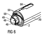
キャップ44が自動注射器1の近位端に配置可能である。キャップ44は、シャシ2の近位端のオリフィス46(図6、図7、図8参照)内に延びるように配置された内部シリンダ45を備える。オリフィス46は、針4よりもかなり幅が広い必要がある。というのは、保護ニードルシールド36および内部シリンダ45用の空間が必要だからである。使用前の初期状態では、内部シリンダ45は、針4を覆うように配置された保護ニードルシールド36をつかんでいる。
A
注射に備えて、キャップ44を取り外さなければならない。図5は、キャップ44を保護ニードルシールド36およびシリンジ3とともに示した等角図である。キャップ44を取り外した後で、保護ニードルシールド36も取り外す。保護ニードルシールド36をシリンジ3から引いて離すのに要する力は比較的大きい。保護ニードルシールド36を取り外しているときにシリンジ3が近位方向Pに引かれないようにするために、シリンジ3は定位置で堅固に保持されなければならない。これは、シリンジ3をその近位端でシリンジ・キャリア7内に支持し、シリンジ・キャリア7をデカップリングキャリア41に結合し、デカップリングキャリア41をプランジャ9に係合させ、プランジャ9をデカップリングスリーブ38に取り付け、デカップリングスリーブ38が、後退スリーブ10の傾斜部56とバー57の間に保持されたくさび55と、後退スリーブ10とによって前進しないようにすることによって達成される。
保護ニードルシールド36を取り外した後では、針4は、もはや保護されていないが、依然としてオリフィス46内にわずかな距離後退して入っている。しかし、オリフィス46はユーザが、少なくとも子供が指で触れる程度には大きい。指が入らないようにするために、ばねワイヤ48がオリフィス46のところに配置されている。ばねワイヤ48はシャシ2に取り付けられ、円弧状の横断線セクション48.1を有する。横断線セクション48.1は、内側に撓むように偏倚しており、そのため、極めて小さな指でも入らないようにオリフィス46を本質的に塞いでいるが、針4がばねワイヤ48に触れずに前進するには十分に中心からずれている(図7および図8参照)。ノッチ49が、オリフィス46の近傍のシャシ2の近位面に配置されており、そのため、ばねワイヤ48がその位置でロックされて、ユーザの指によって容易にはわきへ押されないようになっている。キャップ44が近位端Pに取り付けられている限り、内部シリンダ45により円弧状の横断線セクション48.1が内側に撓まない(図4および図6参照)。図6に、キャップ44が定位置にある状況を、キャップ44自体を除いて示す。図4に、キャップ44を取り外しているときの自動注射器1の近位端を、連動スリーブ25を除いて示す。
After removal of the
ばねワイヤ48により、作動前に針4が近位端Pにできる限り近くなるようにすることができ、それによって、シリンジ3の移動量が少なくなり、自動注射器1の全長が短くなるが、針による突き刺し負傷は依然として防止される。
The
図示の実施形態では、キャップ44は、2つの第4弾性クリップ47によって近位端Pで保持される。キャップ44は、ねじ結合によって自動注射器1に同様に取り付けることもできる。
In the illustrated embodiment, the
キャップ44および保護ニードルシールド36を取り外した後で、自動注射器1の近位端Pを注射部位、例えば患者の皮膚に押しつける。それによって、皮膚連動スリーブ25が、連動ばね26の偏倚に抗して近位側位置から遠位側位置に並進移動する。注射部位に対する圧力が維持または増大されると、スリーブ・トリガ・ボタン20が近位方向Pに並進移動し始める。典型的には、自動注射器1は、トリガ・ボタン20を並進移動させるには連動スリーブ25を並進移動させるよりも大きな力を必要とするように構成されており、そのため、自動注射器1を皮膚に押しつけるときにユーザが感知する力に段差がある2段階操作が提供される。トリガ・ボタン20がシャシ2に対して並進移動すると、くさび55が撓んでバー57の凹部59に入り得るまでバー57も並進移動し、そのため、弾性アーム54、デカップリングスリーブ38、スラスト・カラー37、およびプランジャ9が解放されて、駆動ばね8がこれらを近位方向Pに並進移動させることができる。
After removing the
この時点で駆動ばね8はスラスト・カラー37を近位方向Pに押しつけ、スラスト・カラー37とともに、デカップリングスリーブ38、プランジャ9、デカップリングキャリア41、シリンジ・キャリア7、および針4を備えたシリンジ3を移動させるが、ストッパ6には何の負荷もかけない。中空針4が近位端Pから現れ、注射部位、例えば患者の皮膚に挿入される。
At this point, the
この前方への移動は、シリンジ・キャリア7がシャシ2内の第2当接部32で底に達するまで継続する。初期位置からこの点までの移動量が注射深さ、すなわち針の挿入深さを定義する。
This forward movement continues until the
同時に、後退スリーブ10に対して相対的に移動するデカップリングキャリア41が、後退スリーブ10の開口60に達する。デカップリングキャリア41の第2の弾性クリップ42は、もはや後退スリーブ10によって外側で支持されない。駆動ばね8がプランジャ9を押し続けると、第2の弾性クリップ42が、回転止め43および第2クリップ42の遠位側で傾斜部または丸みを帯びた縁部によって回転止め43から押し出される。もはやデカップリングキャリア41にもシリンジ3にも結合していないプランジャ9が、前進し続け、ストッパ6を押し始め、それによって薬剤Mがシリンジ3から吐き出され、薬剤Mが患者の皮膚の中に、または皮膚を貫通して注射される。
At the same time, the
スラスト・カラー37、デカップリングスリーブ38、および第1のクリップ39が近位方向Pに移動すると、移動シャッタ61および固定シャッタ62の互いに位相がずれたキャスタレーションによって生成される表面に沿って第1のクリップ39がスライドする。
As the
注射中または注射終了時に自動注射器1が注射部位から離されると、連動スリーブ25が連動ばね26の負荷の下で近位方向Pに並進移動する。トリガ・ボタン20およびヘッド部50は自動注射器1にトリガがかけられたときに近位方向Pにすでに並進移動しているので、連動スリーブ25の移動量を制限しているヘッド部50内の第1当接部5が初期状態での位置よりも近位方向Pに寄る。したがって、連動スリーブ25は、その初期近位側位置を超えて近位方向Pに並進移動して、後退スリーブ10の近位端の2つの弾性第3クリップ52間から脚部51が外れる最終的な近位側位置に達し、そのため、弾性第3クリップ52がそれらのシャシ2内での突起53との傾斜係合のために、かつ、後退スリーブ10のスラスト面13を押す駆動ばね8のために内側に撓む。この時点で後退スリーブ10は、シャシ2から外れており、そのため、駆動ばね8はもはやその遠位端で固定されていない。後退スリーブ10は、駆動ばね8の負荷の下で、後退スリーブ10内の第1ショルダ部63がシリンジ・キャリア7上の第2ショルダ部64に当たるまで遠位方向Dに並進移動し、そのため、移動シャッタ61と固定シャッタ62の位相が合い、整列したキャスタレーション間に多数の隙間が連続して生成される。
When the
後退スリーブ25が注射の最中に解放されると、注射は第1のクリップ39が整列したキャスタレーション間の次の隙間に近位方向Pに到達するまで継続する。第1のクリップ39は、スラスト・カラー37との傾斜係合により内側に撓みその隙間に入る。その結果、スラスト・カラー37およびデカップリングスリーブ38の結合が解除され、プランジャ9の前進が停止する。依然として駆動ばね8の力の下にあるスラスト・カラー37は、シャシ上の(図示しない)ストッパに当たるまで継続して移動し、駆動ばね8がその近位端で新たに固定される。依然として駆動ばね8の反対方向の力の下にある後退スリーブ10は、その第1ショルダ63部でシリンジ・キャリア7の第2ショルダ64部を押しており、この時点で、シリンジ・キャリア7、シリンジ3、プランジャ9、およびデカップリングスリーブ38の集合体全体を、自動注射器1内を遠位方向Dに引っ張ることができる。このとき針4は、自動注射器1内の安全な距離のところに戻っており、そのため、注射後の針による突き刺し負傷が防止される。
When the retracting
後退スリーブ25が注射終了時に解放されると、この時点で外れる移動シャッタ61の最も近位側のキャスタレーションまですでに移動している第1のクリップ39は、第1のクリップ39が整列したシャッタ61、62よりも近位側で内側に撓むことができる。スラスト・カラー37およびデカップリングスリーブ38の結合が解除される。依然として駆動ばね8の力の下にあるスラスト・カラー37は、シャシ上の(図示しない)ストッパに当たるまで短い距離移動し続け、駆動ばね8がその近位端で新たに固定され、第1のクリップ39がスラスト・カラー37の下にもぐり込み、そのため、第1のクリップ39はキャスタレーションによって妨げられずに遠位方向Dに並進移動する。駆動ばね8の反対方向の力の下にある後退スリーブ10は、この時点で、シリンジ・キャリア7、シリンジ3、針4、プランジャ9、およびデカップリングスリーブ38の集合体全体を、自動注射器1内を遠位方向Dに引っ張ることができる。このとき針4は、自動注射器1内の安全な距離のところまで戻っており、そのため、注射後の針による突き刺し負傷が防止される。
When the retracting
指ガードとして働くばねワイヤ48は、任意の自動注射器または他の注射デバイスに適用し得る。
The
固定シャッタ62および移動シャッタ61は、プランジャ9のシャシ2に対する相対的な並進移動を制御するためのシャッタ機構の一実施形態を形成する。
The fixed
図9〜図22に、シャッタ機構の代替実施形態を示す。 9-22 show alternative embodiments of the shutter mechanism.
図9に、縦方向に移動可能な構成要素102の並進移動を制御するためのシャッタ機構101を示す。シャッタ機構101は、キャスタレーション103.1〜103.6の形状の1組の固定突起103.1〜103.6を有する少なくとも1つの固定シャッタ103を備え、固定シャッタ103はハウジング104またはシャシの一部であることが好ましい。シャッタ機構101はさらに、縦方向に移動可能な構成要素102に関連する少なくとも1つの弾性アーム105を備える。弾性アーム105の近位側先端において、鈎部106がキャスタレーション103.1〜103.6に向かって弾性的に偏倚しており、そのため、キャスタレーション103.1〜103.6間またはそれらの背後で係合し、縦方向に移動可能な構成要素102の並進移動を妨げる。それぞれの移動シャッタ・アーム107が固定シャッタ103に並んで配置される。移動シャッタ・アーム107は、多数の傾斜し互いに離間した移動突起107.1〜107.6を連続して有し、これらの傾斜部は遠位方向Dに面する。キャスタレーション103.1〜103.6および傾斜突起107.1〜107.6は、同じピッチを有し、輪郭のある面を形成する。移動シャッタ・アーム107は、固定シャッタ103に対して縦方向に移動可能である。移動シャッタ・アーム107は、その傾斜突起107.1〜107.6がキャスタレーション103.1〜103.6と本質的に位相が合った少なくとも1つのロック位置を有し、そのため、弾性アーム105の鈎部106がキャスタレーション103.1〜103.6間またはそれらの背後でひっかかる。移動シャッタ・アーム107は、その傾斜突起107.1〜107.6がキャスタレーション103.1〜103.6と位相がずれた少なくとも1つのロック解除位置を有し、そこでは、傾斜突起107.1〜107.6に妨げられて鈎部106がキャスタレーション103.1〜103.6と係合せず、キャスタレーション103.1〜103.6が外れ、そのため、縦方向に移動可能な構成要素102が並進移動し得る。
FIG. 9 shows a
縦方向に移動可能な構成要素102は、好ましくは、駆動手段、例えば、ばねの駆動力をシリンジ108またはシリンジ108を封止するためのストッパ109に伝え、シリンジ108から液体薬剤を移動させるためのプランジャ102である。シリンジ108、シャッタ機構101、プランジャ102、および駆動手段は、薬剤を送達するための自動注射器の一部とし得る。
The longitudinally
図9に、注射中のシャッタ機構101を示す。
FIG. 9 shows the
使用前に、プランジャ102は、近位方向Pに働く駆動力を分解して固定シャッタ103に伝える。移動シャッタ・アーム107は、固定シャッタ103と位相が合っており、したがって何ら負荷を担持しない。鈎部106が最も遠位側のキャスタレーション103.1の背後でひっかかっているので、プランジャ102を近位方向Pに押し込むことができない。
Prior to use, the
プランジャ102を近位方向Pに並進移動させるために、移動シャッタ・アーム107が固定シャッタ103に対して相対的に遠位方向Dに並進移動されなければならず、それによって両者の位相がずれる。移動シャッタ・アーム107の最も遠位側の移動突起107.1の傾斜部が鈎部106にカムとして作用して固定シャッタ103との係合を解除し、それによって鈎部106が第1キャスタレーション103.1の上部と同じ高さになる。この時点で、プランジャ102は、駆動力の下で近位方向Pに移動自由になる。シャッタ103、107の相対位置が一定に保持される場合、図9に示すように、鈎部106は、互いに位相がずれている固定シャッタ103と移動シャッタ・アーム107によって形成される表面上に乗り、その状態が近位方向Pに継続する。
In order to translate the
図9および図10に示す実施形態では、表面に沿って移動する鈎部106は、固定シャッタ103のキャスタレーション103.1〜103.6の上部から離れるたびに音を発生し、鈎部106が移動突起107.1〜107.6の傾斜部に乗るときに移動シャッタ・アーム107に交互に力を加える。これにより、注射が行われていることの可聴かつ触知できるフィードバックが得られる。これらがなくなると、注射が完了する。
In the embodiment shown in FIG. 9 and FIG. 10, the
注射中に、移動シャッタ・アーム107が(移動シャッタ・アーム107を、さらに遠位方向Dに移動させるか、または、薬剤注射前の位置に向かって移動させることによって)並進移動して戻り、固定シャッタ103と位相が合うと、鈎部106が、次の固定シャッタ103のキャスタレーション103.1〜103.6にひっかかり、注射を停止させる。次いで、移動シャッタ・アーム107を並進移動させて固定シャッタ103と再び位相が合うと、注射を再開することができる。あるいは、移動シャッタ・アーム107がラッチされるか、またはユーザの制御から切断されてもよく、この場合にはさらなる薬剤送達はなされない。
During injection, the moving
図11に、シャッタ機構101の代替実施形態を示す。移動シャッタ・アーム107は1つだけ傾斜した移動突起107.1を有し、他の移動突起107.2〜107.6はキャスタレーションである。プランジャ102の並進移動中に移動シャッタ・アーム107が並進移動されて固定シャッタ103と位相が合うと、鈎部106は撓んでキャスタレーション103.1〜103.5、107.1〜107.6間の次の空間に入り、そこに留まる。というのは、鈎部106が移動シャッタ・アーム107によって再び傾斜を利用して出ることがないからである。したがって、注射は一度停止すると再開することができない。図11の実施形態では、プランジャ102の並進移動中に、例えば注射中に、可聴フィードバックも触知できるフィードバックも得られない。
FIG. 11 shows an alternative embodiment of the
図12に、シャッタ機構101の別の実施形態を示す。この実施形態では、固定キャスタレーション103.1が1つだけ固定シャッタ103上に設けられ、傾斜した移動突起107.1が1つだけ移動シャッタ・アーム107上に設けられる。プランジャ102を近位方向Pに並進移動させるために、移動シャッタ・アーム107が固定シャッタ103に対して相対的に遠位方向Dに並進移動されなければならず、それによって図12に示すように両者の位相がずれる。移動突起107.1の傾斜部が鈎部106にカムとして作用して固定シャッタ103との係合を解除し、それによって鈎部106が固定キャスタレーション103.1の上部と同じ高さになる。この時点で、プランジャ102は、駆動力の下で近位方向Pに移動自由になる。この時点からは注射が継続され、ユーザが注射を一時的または完全に停止することはできない。図12の実施形態では、プランジャ102の並進移動中、例えば注射中に可聴フィードバックも触知できるフィードバックも得られない。
FIG. 12 shows another embodiment of the
図13は、1組のキャスタレーション103.1〜103.5が固定シャッタ103上に設けられ、傾斜部107.1が1つだけ移動シャッタ・アーム107上に設けられるシャッタ機構の実施形態である。傾斜部107.1の近端側では、移動シャッタ・アーム107は傾斜部107.1の上部の高さのままである。プランジャ102を近位方向Pに並進移動させるために、移動シャッタ・アーム107が固定シャッタ103に対して相対的に遠位方向Dに並進移動されなければならず、それによって図13に示すように両者の位相がずれる。移動シャッタ・アーム107の傾斜部107.1が鈎部106にカムとして作用して固定シャッタ103との係合を解除し、それによって鈎部106が固定キャスタレーション103.1の上部と同じ高さになる。この時点で、プランジャ102は、駆動力の下で近位方向Pに移動自由になる。この時点からは注射が継続され、ユーザが注射を一時的または完全に停止することはできない。図13の実施形態では、プランジャ102の並進移動中、例えば注射中に可聴フィードバックも触知できるフィードバックも得られない。この実施形態では、図9および図10の実施形態と同じ固定シャッタ103が統合されたハウジング104を用いることができる。改変された移動シャッタ・アーム107を適用するだけで機能が変更される。これにより、多くの部品を共通とする自動注射器のプラットホームを生成することができ、機能を変更するためにはいくつかの部品のみを交換すればよい。
FIG. 13 shows an embodiment of a shutter mechanism in which a set of castellations 103.1 to 103.5 is provided on the fixed
図14は、シャッタ機構101のさらに別の実施形態である。このシャッタ機構101は、1組の傾斜した固定突起103.1〜103.5の形状の少なくとも1つの固定シャッタ103を備える。固定シャッタ103の傾斜した固定突起103.1〜103.5の傾斜部は近位方向Pに面する。移動シャッタ・アーム107は、固定シャッタ103に並んで配置され、多数の傾斜し互いに離間した移動突起107.1〜107.6を連続して有し、これらの傾斜部は遠位方向Dに面する。固定シャッタ103の傾斜した固定突起103.1〜103.5および移動シャッタ・アーム107の傾斜した移動突起107.1〜107.6は、同じピッチを有し、輪郭のある面を形成する。移動シャッタ・アーム107は、固定シャッタ103に対して縦方向に移動可能である。移動シャッタ・アーム107は、その傾斜した移動突起107.1〜107.6が固定シャッタ103の傾斜した固定突起103.1〜103.5と本質的に位相が合った少なくとも1つのロック位置を有し、そのため、弾性アーム105の鈎部106が固定シャッタ103の傾斜した固定突起103.1〜103.5間またはそれらの背後でひっかかる。移動シャッタ・アーム107は、その傾斜した移動突起107.1〜107.6が傾斜した固定突起103.1〜103.5と位相がずれた少なくとも1つのロック解除位置を有し、そのため、傾斜した移動突起107.1〜107.6に妨げられて鈎部106が傾斜した固定突起103.1〜103.5と係合せず、固定突起103.1〜103.5が外れ、そのため、縦方向に移動可能な構成要素102が並進移動し得る。
FIG. 14 shows still another embodiment of the
使用前に、プランジャ102は、近位方向Pに働く駆動力を分解して固定シャッタ103に伝える。移動シャッタ・アーム107は、固定シャッタ103と位相が合っており、したがって何ら負荷を担持しない。プランジャ102は、鈎部106が固定シャッタ103の最も遠位側の傾斜した固定突起103.1の背後でひっかかっているので、近位方向Pに押し込むことができない。
Prior to use, the
プランジャ102を近位方向Pに並進移動させるために、移動シャッタ・アーム107が固定シャッタ103に対して相対的に遠位方向Dに並進移動されなければならず、それによって両者の位相がずれる。移動シャッタ・アーム107の最も遠位側の傾斜した移動突起107.1の傾斜部が鈎部106にカムとして作用して固定シャッタ103との係合を解除し、それによって鈎部106が傾斜した固定突起103.1の上部と同じ高さになる。この時点で、プランジャ102は、駆動力の下で近位方向Pに移動自由になる。シャッタ103、107の相対位置が一定に保持される場合、鈎部106は、互いに位相がずれている固定シャッタ103および移動シャッタ・アーム107によって形成される表面の上下に乗り、その状態が継続する。
In order to translate the
図14に示す実施形態では、表面に沿って移動する鈎部106は、注射が行われていることの可聴かつ触知できるフィードバックを提供するが、図9の実施形態と比較すると音が小さくなる。
In the embodiment shown in FIG. 14, the
図9の実施形態と同様に、注射を中断し再開することができる。さらに、キャスタレーションの代わりの固定シャッタ103の傾斜した固定突起103.1〜103.5によりプランジャ102を後退させることができ、その結果、シリンジ108および針が後退する。これは、固定シャッタ103と移動シャッタ・アーム107が図14に示すように位相が互いにずれていると、鈎部106がシャッタ103、107のいずれの傾斜した突起103.1〜103.5、107.1〜107.6間にもひっかからずに遠位方向Dにも移動できるからである。
Similar to the embodiment of FIG. 9, the injection can be interrupted and resumed. Furthermore, the
図15は、シャッタ機構101の別の実施形態である。このシャッタ機構101は、1組の固定突起103.1〜103.5を伴う少なくとも1つの固定シャッタ103を備え、これらの固定突起の最も遠位側の突起がキャスタレーション103.1の形状をしており、他の突起103.2〜103.5が傾斜しており、これらの傾斜部が遠位方向Dに面している。移動シャッタ・アーム107は、固定シャッタ103と並んで配置されており、1つの傾斜した突起107.1を有し、その傾斜部が遠位方向Dに面している。移動シャッタ・アーム107は、固定シャッタ103に対して縦方向に移動可能である。
FIG. 15 shows another embodiment of the
使用前に、プランジャ102は、近位方向Pに働く駆動力を分解して固定シャッタ103の固定キャスタレーション103.1に伝える。移動シャッタ・アーム107の傾斜した移動突起107.1は、固定シャッタ103の固定キャスタレーション103.1と位相が合っている。プランジャ102は、鈎部106が固定シャッタ103の固定キャスタレーション103.1の背後でひっかかっているので、近位方向Pに押し込むことができない。
Prior to use, the
プランジャ102を近位方向Pに並進移動させるために、移動シャッタ・アーム107が固定シャッタ103に対して相対的に遠位方向Dに並進移動されなければならず、それによって両者の位相がずれる。傾斜した移動突起107.1の傾斜部が鈎部106にカムとして作用して固定シャッタ103との係合を解除し、それによって鈎部106が第1固定突起103.1の上部と同じ高さになる。この時点で、プランジャ102は、駆動力の下で近位方向Pに移動自由になる。この時点からは注射が継続され、ユーザが注射を一時的または完全に停止することはできない。鈎部106は、固定突起103.2〜103.5によって形成される表面の上下に乗り、その状態が継続する。
In order to translate the
図15に示す実施形態では、表面に沿って移動する鈎部106は、注射が行われていることの可聴フィードバックのみを提供する。移動シャッタ107が傾斜した突起107.2〜107.6を有し、固定シャッタ103が傾斜した突起も有していない場合には、このシャッタ機構101は触知できるフィードバックも提供し得る。
In the embodiment shown in FIG. 15, the
図16Aおよび図16Bに、シャッタ機構101のさらに別の実施形態を示す。
16A and 16B show still another embodiment of the
このシャッタ機構101は、一方の側に突出するキャスタレーションの形状の1組の固定突起103.1〜103.5を伴う少なくとも1つの固定シャッタ103を備える。移動シャッタ・アーム107は固定シャッタ103に並んで配置される。移動シャッタ・アーム107は、反対側に突出した傾斜移動突起107.1〜107.7を有し、これらの傾斜部は遠位方向Dに面し、固定シャッタ103の対合傾斜部110.1〜110.7と係合する。移動シャッタ・アーム107は、固定シャッタ103に対して縦方向に移動可能である。
This
使用前に(図16A参照)、プランジャ102は、近位方向Pに働く駆動力を分解して固定シャッタ103の固定キャスタレーション103.1に伝える。移動シャッタ・アーム107の傾斜した移動突起107.1〜107.7は、固定シャッタ103の対合傾斜部110.1〜110.7と完全に係合する。プランジャ102は、鈎部106が固定シャッタ103の固定キャスタレーション103.1の背後でひっかかっているので、近位方向Pに押し込むことができない。
Prior to use (see FIG. 16A), the
プランジャ102を近位方向Pに並進移動させるために、移動シャッタ・アーム107が固定シャッタ103に対して相対的に遠位方向Dに並進移動されなければならない。互いに係合した傾斜移動突起107.1〜107.7と対合傾斜部110.1〜110.7は、移動シャッタ・アーム107を固定シャッタ103から離れるように押す。それによって、突起107.1〜107.7の反対側である移動シャッタ・アーム107の裏側が、固定突起103.1〜103.5の上部と同じ高さになり、そのため、鈎部106が固定シャッタ103から外れる(図16B参照)。この時点で、プランジャ102は、駆動力の下で近位方向Pに移動自由になる。シャッタ103、107の相対位置が一定に保持される場合、鈎部106は、固定シャッタ103および移動シャッタ・アーム107によって形成される表面の上に乗り、その状態が近位方向Pに継続する。
In order to translate the
移動シャッタ・アーム107が近位方向Pに並進移動して戻る場合、移動シャッタ107はもはや固定シャッタ103から離されず、傾斜した移動突起107.1〜107.7と対合傾斜部110.1〜110.7が完全に再係合する。鈎部106が、次の固定シャッタ103のキャスタレーション103.1〜103.6にひっかかり、注射を停止する。次いで、移動シャッタ・アーム107を遠位方向Dに再度並進移動させることによって注射を再開し得る。
When the moving
図16Aおよび図16Bの実施形態では、移動突起107.1〜107.7の数および固定突起103.1〜103.5のピッチに対する移動突起107.1〜107.7のピッチは、プランジャ102の近位方向移動を開始または停止させるのに必要とされる移動シャッタ・アーム107の遠位方向移動量を定義すること以外は重要ではない。1つの移動突起107.1および1つの対合傾斜部110.1があれば十分である。しかし、少なくとも2つの移動突起107.1〜107.7および2つの対合傾斜部110.1〜110.7があればより堅固である。
In the embodiment of FIGS. 16A and 16B, the number of moving protrusions 107.1 to 107.7 and the pitch of moving protrusions 107.1 to 107.7 relative to the pitch of fixed protrusions 103.1 to 103.5 is It is not important other than defining the amount of distal movement of the moving
図16Aおよび図16Bの実施形態では、可聴フィードバックも触知できるフィードバックも提供されない。というのは、固定シャッタ103と移動シャッタ107の間で位相を合わせる必要性がないからであり、固定突起103.1〜103.5は、薄くかつ互いに近づけることができ、その結果、停止位置の分解能が向上する。固定突起103.1〜103.5間の距離が傾斜部の長さによって決まり、傾斜部の長さが鈎部106を解放するために指定される力/変位によって決まる先に述べた実施形態と異なり、図16Aおよび図16Bの実施形態では、移動突起107.1〜107.7の傾斜部は固定突起103.1〜103.5と無関係である。したがって、離間した固定突起103.1〜103.nをより近接させると、停止位置の分解能を向上することができる。
The embodiment of FIGS. 16A and 16B provides neither audible feedback nor tactile feedback. This is because it is not necessary to match the phase between the
図17、図18、および図19に、図9および図10の実施形態の変形形態を示す。 17, 18 and 19 show a variation of the embodiment of FIGS.
図17では、最も遠位側の傾斜した移動突起107.1より遠位側の移動シャッタ・アーム107のレベルならびに最も遠位側の固定突起103.1より遠位側の固定シャッタ103の高さが、突起103.1〜103.5間、107.1〜107.6間の高さよりも低い。その結果、傾斜した移動突起107.1の傾斜部がより長くなり、鈎部106にその使用前の位置(突起103.1、107.1より遠位側)からカム作用を施すには、移動シャッタ107の移動量を、注射を再開するための移動量よりも大きくする必要がある。こうすると、移動シャッタ・アーム107の初期移動に対するシャッタ構成の感度が下がり、それによって、注射の開始時に誤ってトリガをかける可能性が減少するが、迅速に停止させる能力は維持される。停止点間の分解能がよくなる。
In FIG. 17, the level of the moving
図18では、最も遠位側の傾斜した移動突起107.1の傾斜部が他の傾斜した移動突起107.2〜107.6の傾斜部よりも急である。その結果、鈎部106にその使用前の位置(突起103.1、107.1より遠位側)からカム作用を施すには、移動シャッタ107にかかる力を、注射を再開させる力よりも大きくする必要がある。これにより、注射の開始時に意図しないトリガがかかる可能性が減少する。
In FIG. 18, the inclined part of the most distally inclined moving projection 107.1 is steeper than the inclined parts of the other inclined moving protrusions 107.2 to 107.6. As a result, in order to apply cam action to the
注射を停止/再開し得る実施形態では、注射が実際に停止する前に或る量の液体薬剤が常に吐き出される。というのは、鈎部106が次の固定突起103.1〜103.5の遠位側縁部まで移動しなければならないからである。この薬剤の量を減らすために、自動注射器は、互いに位相がずれた少なくとも2つのシャッタ機構101(例えば、自動注射器のそれぞれの側に1つ)を備えればよい。こうすると、シャッタ機構101の有効ピッチが半分になり、停止するまでに吐き出される薬剤の量がかなり減少する。
In embodiments where injection can be stopped / resumed, an amount of liquid medication is always expelled before the injection actually stops. This is because the
図19では、固定突起103.1〜103.6および移動突起107.1〜107.7は互いに異なる長さを有する。プランジャ102の並進移動を制御するには、固定突起103.1〜103.6によって移動突起107.1〜107.7の近位側縁部を覆うようにすれば十分である。完全に重なる必要はない。こうすると、シャッタのピッチが短くなって、注射を中断したときに送達される量の薬剤がより少なくなる。この構成では、鈎部106の軸方向の幅を、移動シャッタ・アーム107が移動して固定シャッタ103と位相がずれたときに鈎部106が移動突起107.1〜107.7の近位側縁部と固定突起103.1〜103.6の遠位側縁部の間で係合するように十分に短くする必要がある。
In FIG. 19, the fixed protrusions 103.1 to 103.6 and the moving protrusions 107.1 to 107.7 have different lengths. To control the translational movement of the
このシャッタ機構101は、プランジャ102以外の縦方向に移動可能な構成要素102の並進移動の制御が必要とされる他の環境でも同様に適用し得る。
The
固定突起103.1〜103.6および移動突起107.1〜107.7の数は、上記実施形態で示した数と異なり得る。 The number of fixed protrusions 103.1 to 103.6 and moving protrusions 107.1 to 107.7 may be different from the number shown in the above embodiment.
好ましくは、移動シャッタ・アーム107の動きは、自動注射器の近位端を注射部位、例えば患者の皮膚に押しつけることによって作動することができ、それによって、自動注射器の近位端から遠位方向に突出するスリーブまたはバーが押される。この動きは、端部のボタンを押すことによって、あるいは側部のボタンまたは端部のボタンに連結したカムまたは他の機構を介して間接的に押すことによっても同様に作動させることができる。
Preferably, the movement of the moving
これに加えて、自動注射器には2次的な機構によってトリガをかけることができ、シャッタ機構101は単に制御機構として使用し得る。この実装形態では、移動シャッタ107の位置は、「一時停止」ボタンによって制御される。こうすると、自動注射器から薬剤注射させる機構と自動注射器を一時停止する機構を分離することができ、そのため有用性が改善する。
In addition, the auto-injector can be triggered by a secondary mechanism, and the
この「一時停止ボタン」は、「押して注射する」か、または「押して一時停止する」ように設計し得る。この機構が「押して注射する」ようになっている場合、一時停止ボタンとトリガを組み合わせることができる。 This “pause button” may be designed to “push and inject” or “push and pause”. If the mechanism is to “push and inject”, the pause button and trigger can be combined.
代替実施形態では、図示した実施形態のように移動シャッタ107を縦方向に並進移動させるのではなく、シャッタに直交する方向に回転または並進移動させて、固定突起103.1〜103.5間の隙間に入るように構成し得る。
In an alternative embodiment, the
図20に示すさらに別の代替実施形態では、シャッタ103、107を互いに対向させ、プランジャ102がシャッタ103と107の間に生成される隙間を通り抜けるようにし得る。この構成では、固定突起103.1〜103.5および移動突起107.1〜107.6が移動されて位相がずれたときに形成される通路に沿って鈎部106を通過させるために、これらの突起の遠位面の遠位面がともに傾斜している必要がある。
In yet another alternative embodiment shown in FIG. 20, the
さらに別の実施形態では、2つのシャッタ103、107に切れ込みを入れて形成した連続した正弦波状の通路を通して鈎部106を振動させることができる(図21および図22参照)。この正弦波状の通路は、移動シャッタ107をロック位置にシフトさせることによって壊れ、そのため、鈎部106はシャッタ103と107の間の次の切替え部よりも先に前進できない。
In yet another embodiment, the
1 自動注射器
2 シャシ
3 シリンジ
4 中空針
5 第1当接部
6 ストッパ
7 シリンジ・キャリア
8 駆動ばね
9 プランジャ
10 後退スリーブ
13 スラスト面
20 トリガ・ボタン
25 連動スリーブ
26 連動ばね
32 第2当接部
36 保護ニードルシールド
37 スラスト・カラー
38 デカップリングスリーブ
39 第1弾性クリップ
41 デカップリングキャリア
42 第2の弾性クリップ
43 回転止め
44 キャップ
45 内部シリンダ
46 オリフィス
47 第4弾性クリップ
48 ばねワイヤ
48.1 円弧状の横断線セクション
49 ノッチ
50 ヘッド部
51 脚部
52 第3の弾性クリップ
53 突起
54 弾性アーム
55 くさび
56 傾斜部
57 バー
58 遠位端面
60 開口
61 移動シャッタ
62 固定シャッタ
63 第1ショルダ
64 第2ショルダ
101 シャッタ機構
102 縦方向に移動可能な構成要素、プランジャ
103 固定シャッタ
103.1...103.n 固定突起、キャスタレーション
104 ハウジング
105 弾性アーム
106 鈎部
107 移動シャッタ・アーム
107.1...107.n 移動突起、傾斜
108 シリンジ
109 ストッパ
110.1...110.7 対合傾斜部
D 遠位端、遠位方向
M 薬剤
P 近位端、近位方向
DESCRIPTION OF
Claims (6)
ンジ(3)はシャシ(2)に対してスライド可能に配置され、自動注射器はさらに、
−起動時、
−針(4)をシャシ(2)内の覆われた位置からオリフィス(46)を通り前進位置に押すこと、
−シリンジ(3)を操作して薬剤(M)の用量を供給すること、
−薬剤(M)送達後、針(4)とともにシリンジ(3)を覆われた位置に後退させること、
が可能な駆動手段(8)、
−手動操作前は駆動手段(8)をロックするように構成され、手動操作時注射のために駆動ばね(8)を解放し得る起動手段(20)、
を含む、上記自動注射器。 An automatic injector (1) for administering a dose of liquid medicament (M) comprising a finger guard according to claim 4, wherein the chassis (2) seals the needle (4) and the syringe (3). It is configured to include a syringe (3) with a stopper (6) for moving the stop drug (M), the syringe (3) is slidably arranged with respect to the chassis (2), and the automatic injector is further,
-At startup,
-Pushing the needle (4) from the covered position in the chassis (2) through the orifice (46) to the advanced position;
-Manipulating the syringe (3) to supply a dose of the drug (M);
-Withdrawing the syringe (3) together with the needle (4) to the covered position after delivery of the drug (M);
Drive means (8) capable of
An activation means (20) configured to lock the drive means (8) prior to manual operation and capable of releasing the drive spring (8) for injection during manual operation;
Including the automatic syringe.
Applications Claiming Priority (5)
| Application Number | Priority Date | Filing Date | Title |
|---|---|---|---|
| EP10187009A EP2438952A1 (en) | 2010-10-08 | 2010-10-08 | Finger guard for an injection device |
| EP10187009.5 | 2010-10-08 | ||
| US201161432256P | 2011-01-13 | 2011-01-13 | |
| US61/432,256 | 2011-01-13 | ||
| PCT/EP2011/067503 WO2012045840A1 (en) | 2010-10-08 | 2011-10-06 | Finger guard for an injection device |
Publications (3)
| Publication Number | Publication Date |
|---|---|
| JP2013539686A JP2013539686A (en) | 2013-10-28 |
| JP2013539686A5 JP2013539686A5 (en) | 2014-11-06 |
| JP6099567B2 true JP6099567B2 (en) | 2017-03-22 |
Family
ID=43513747
Family Applications (1)
| Application Number | Title | Priority Date | Filing Date |
|---|---|---|---|
| JP2013532210A Active JP6099567B2 (en) | 2010-10-08 | 2011-10-06 | Finger guard for injection device |
Country Status (8)
| Country | Link |
|---|---|
| US (1) | US9205200B2 (en) |
| EP (2) | EP2438952A1 (en) |
| JP (1) | JP6099567B2 (en) |
| AR (1) | AR083349A1 (en) |
| CA (1) | CA2811850A1 (en) |
| DK (1) | DK2624895T3 (en) |
| TW (1) | TWI572383B (en) |
| WO (1) | WO2012045840A1 (en) |
Families Citing this family (9)
| Publication number | Priority date | Publication date | Assignee | Title |
|---|---|---|---|---|
| IN2014CN03380A (en) | 2011-11-07 | 2015-10-09 | Safety Syringes Inc | |
| EP2601992A1 (en) | 2011-12-08 | 2013-06-12 | Sanofi-Aventis Deutschland GmbH | Syringe carrier |
| USD721802S1 (en) * | 2012-03-23 | 2015-01-27 | Terumo Kabushiki Kaisha | Intradermal injection device |
| MA41101A (en) * | 2014-12-03 | 2017-10-10 | Lilly Co Eli | AUTOMATIC DRUG INJECTION DEVICE WITH AUDIBLE INDICATION OF INJECTION PROGRESS |
| TW201700117A (en) * | 2015-06-03 | 2017-01-01 | 賽諾菲阿凡提斯德意志有限公司 | Syringe carrier for an autoinjector and method of assembling |
| TW201705994A (en) | 2015-06-03 | 2017-02-16 | 賽諾菲阿凡提斯德意志有限公司 | Autoinjector and method of assembling |
| US20190209780A1 (en) * | 2016-05-30 | 2019-07-11 | Blue Lead Medical Llc | Autoinjector and user wearable autoinjector assembly |
| CN110292683B (en) * | 2019-07-31 | 2023-09-22 | 派格生物医药(苏州)有限公司 | Automatic injection pen with passive trigger |
| CN115869489B (en) * | 2023-03-02 | 2023-08-25 | 四川省医学科学院·四川省人民医院 | Intravenous injection needle under endoscope |
Family Cites Families (14)
| Publication number | Priority date | Publication date | Assignee | Title |
|---|---|---|---|---|
| US4795432A (en) * | 1987-02-19 | 1989-01-03 | Karczmer Claude M | Shield assembly for hypodermic injection devices |
| US7300416B2 (en) * | 1995-08-22 | 2007-11-27 | Specialized Health Products International | Pre-filled retractable needle injection ampoules |
| SE9803662D0 (en) * | 1998-10-26 | 1998-10-26 | Pharmacia & Upjohn Ab | autoinjector |
| JP2001259034A (en) * | 2000-03-22 | 2001-09-25 | Kawasumi Lab Inc | Bellows-shaped elastic needle cover and safety deice for preventing erroneous needling with the needle cover |
| AU2001281753A1 (en) | 2000-08-29 | 2002-03-13 | Novo-Nordisk A/S | Automatic injection device with torsion function for retraction of needle |
| WO2002074369A1 (en) * | 2001-03-20 | 2002-09-26 | Disetronic Licensing Ag | Needle protective covering |
| EP1572271A1 (en) * | 2002-11-25 | 2005-09-14 | Tecpharma Licensing AG | Auto-injector comprising a resettable releasing safety device |
| US20050027255A1 (en) * | 2003-07-31 | 2005-02-03 | Sid Technologies, Llc | Automatic injector |
| WO2005079891A1 (en) * | 2004-02-13 | 2005-09-01 | Smiths Medical Asd, Inc. | Needle tip protector |
| US20070088260A1 (en) * | 2005-10-05 | 2007-04-19 | Kai-Hsiang Peng | Syringe with safety cap |
| WO2008047372A2 (en) * | 2006-10-19 | 2008-04-24 | Elcam Medical Agricultural Cooperative Association Ltd. | Automatic injection device |
| CA2645972A1 (en) * | 2007-12-14 | 2009-06-14 | Tyco Healthcare Group Lp | Safety needle assembly |
| GB2478349A (en) * | 2010-03-05 | 2011-09-07 | Owen Mumford Ltd | Injection device having projections reducing the diameter of the syringe passage |
| EP2438947A1 (en) * | 2010-10-08 | 2012-04-11 | Sanofi-Aventis Deutschland GmbH | Auto-injector |
-
2010
- 2010-10-08 EP EP10187009A patent/EP2438952A1/en not_active Ceased
-
2011
- 2011-10-06 CA CA2811850A patent/CA2811850A1/en not_active Abandoned
- 2011-10-06 TW TW100136195A patent/TWI572383B/en not_active IP Right Cessation
- 2011-10-06 JP JP2013532210A patent/JP6099567B2/en active Active
- 2011-10-06 EP EP11767431.7A patent/EP2624895B1/en active Active
- 2011-10-06 US US13/877,496 patent/US9205200B2/en active Active
- 2011-10-06 DK DK11767431.7T patent/DK2624895T3/en active
- 2011-10-06 AR ARP110103713A patent/AR083349A1/en not_active Application Discontinuation
- 2011-10-06 WO PCT/EP2011/067503 patent/WO2012045840A1/en active Application Filing
Also Published As
| Publication number | Publication date |
|---|---|
| EP2624895A1 (en) | 2013-08-14 |
| US9205200B2 (en) | 2015-12-08 |
| EP2624895B1 (en) | 2015-09-02 |
| DK2624895T3 (en) | 2015-12-07 |
| TW201231120A (en) | 2012-08-01 |
| CA2811850A1 (en) | 2012-04-12 |
| WO2012045840A1 (en) | 2012-04-12 |
| AR083349A1 (en) | 2013-02-21 |
| US20130317449A1 (en) | 2013-11-28 |
| JP2013539686A (en) | 2013-10-28 |
| EP2438952A1 (en) | 2012-04-11 |
| TWI572383B (en) | 2017-03-01 |
Similar Documents
| Publication | Publication Date | Title |
|---|---|---|
| JP6018066B2 (en) | Automatic syringe | |
| JP6099567B2 (en) | Finger guard for injection device | |
| TWI541039B (en) | Auto-injector | |
| JP6301654B2 (en) | Automatic syringe | |
| JP5926733B2 (en) | Arrangement for coupling plunger to syringe or stopper | |
| TWI537021B (en) | Auto-injector | |
| EP2654833B1 (en) | Auto-injector | |
| JP5889292B2 (en) | Automatic syringe | |
| JP6285182B2 (en) | Automatic syringe | |
| JP5914472B2 (en) | Needle safety device and method for operating the same | |
| JP5914471B2 (en) | Needle safety device and method for operating the same | |
| JP5938412B2 (en) | Reusable engine for auto syringe |
Legal Events
| Date | Code | Title | Description |
|---|---|---|---|
| A521 | Request for written amendment filed |
Free format text: JAPANESE INTERMEDIATE CODE: A523 Effective date: 20140917 |
|
| A621 | Written request for application examination |
Free format text: JAPANESE INTERMEDIATE CODE: A621 Effective date: 20140917 |
|
| A977 | Report on retrieval |
Free format text: JAPANESE INTERMEDIATE CODE: A971007 Effective date: 20150826 |
|
| A131 | Notification of reasons for refusal |
Free format text: JAPANESE INTERMEDIATE CODE: A131 Effective date: 20150901 |
|
| A131 | Notification of reasons for refusal |
Free format text: JAPANESE INTERMEDIATE CODE: A131 Effective date: 20160510 |
|
| A521 | Request for written amendment filed |
Free format text: JAPANESE INTERMEDIATE CODE: A523 Effective date: 20160808 |
|
| TRDD | Decision of grant or rejection written | ||
| A01 | Written decision to grant a patent or to grant a registration (utility model) |
Free format text: JAPANESE INTERMEDIATE CODE: A01 Effective date: 20170131 |
|
| A61 | First payment of annual fees (during grant procedure) |
Free format text: JAPANESE INTERMEDIATE CODE: A61 Effective date: 20170221 |
|
| R150 | Certificate of patent or registration of utility model |
Ref document number: 6099567 Country of ref document: JP Free format text: JAPANESE INTERMEDIATE CODE: R150 |
|
| R250 | Receipt of annual fees |
Free format text: JAPANESE INTERMEDIATE CODE: R250 |
|
| R250 | Receipt of annual fees |
Free format text: JAPANESE INTERMEDIATE CODE: R250 |
|
| R250 | Receipt of annual fees |
Free format text: JAPANESE INTERMEDIATE CODE: R250 |
|
| R250 | Receipt of annual fees |
Free format text: JAPANESE INTERMEDIATE CODE: R250 |
|
| R250 | Receipt of annual fees |
Free format text: JAPANESE INTERMEDIATE CODE: R250 |