JP6098552B2 - Charging method - Google Patents
Charging method Download PDFInfo
- Publication number
- JP6098552B2 JP6098552B2 JP2014045033A JP2014045033A JP6098552B2 JP 6098552 B2 JP6098552 B2 JP 6098552B2 JP 2014045033 A JP2014045033 A JP 2014045033A JP 2014045033 A JP2014045033 A JP 2014045033A JP 6098552 B2 JP6098552 B2 JP 6098552B2
- Authority
- JP
- Japan
- Prior art keywords
- charging
- power
- value
- storage device
- completion
- Prior art date
- Legal status (The legal status is an assumption and is not a legal conclusion. Google has not performed a legal analysis and makes no representation as to the accuracy of the status listed.)
- Expired - Fee Related
Links
Images


Classifications
-
- Y—GENERAL TAGGING OF NEW TECHNOLOGICAL DEVELOPMENTS; GENERAL TAGGING OF CROSS-SECTIONAL TECHNOLOGIES SPANNING OVER SEVERAL SECTIONS OF THE IPC; TECHNICAL SUBJECTS COVERED BY FORMER USPC CROSS-REFERENCE ART COLLECTIONS [XRACs] AND DIGESTS
- Y02—TECHNOLOGIES OR APPLICATIONS FOR MITIGATION OR ADAPTATION AGAINST CLIMATE CHANGE
- Y02E—REDUCTION OF GREENHOUSE GAS [GHG] EMISSIONS, RELATED TO ENERGY GENERATION, TRANSMISSION OR DISTRIBUTION
- Y02E60/00—Enabling technologies; Technologies with a potential or indirect contribution to GHG emissions mitigation
- Y02E60/10—Energy storage using batteries
-
- Y—GENERAL TAGGING OF NEW TECHNOLOGICAL DEVELOPMENTS; GENERAL TAGGING OF CROSS-SECTIONAL TECHNOLOGIES SPANNING OVER SEVERAL SECTIONS OF THE IPC; TECHNICAL SUBJECTS COVERED BY FORMER USPC CROSS-REFERENCE ART COLLECTIONS [XRACs] AND DIGESTS
- Y02—TECHNOLOGIES OR APPLICATIONS FOR MITIGATION OR ADAPTATION AGAINST CLIMATE CHANGE
- Y02T—CLIMATE CHANGE MITIGATION TECHNOLOGIES RELATED TO TRANSPORTATION
- Y02T10/00—Road transport of goods or passengers
- Y02T10/60—Other road transportation technologies with climate change mitigation effect
- Y02T10/70—Energy storage systems for electromobility, e.g. batteries
Landscapes
- Secondary Cells (AREA)
- Electric Propulsion And Braking For Vehicles (AREA)
- Charge And Discharge Circuits For Batteries Or The Like (AREA)
Description
この発明は、充電方法に係り、車両における二次電池の充電方法に関する。 The present invention relates to a charging method, and more particularly to a method for charging a secondary battery in a vehicle.
近年、モータからの駆動力により走行するプラグインハイブリッド車(PHV)や電気自動車(EV)等が注目されている。このような車両には、モータへ電力を供給するためのバッテリ(リチウムイオン二次電池)等の蓄電装置が搭載されており、商用電源等の外部電源からの電力を充電装置を用いて蓄電装置に充電する際に、あらかじめ車両の使用者が設定した充電完了予定時刻に蓄電装置への充電を完了させる、いわゆるタイマ充電を行う技術が広く知られている。一般的に、蓄電装置への充電を行うと、蓄電装置の発熱により蓄電装置の温度が上昇しやすい。蓄電装置の温度が上昇すると、蓄電装置の寿命に悪影響を与えたり、蓄電装置が損傷したりする恐れがあるという問題点があった。 In recent years, a plug-in hybrid vehicle (PHV), an electric vehicle (EV), or the like that travels by driving force from a motor has attracted attention. Such a vehicle is equipped with a power storage device such as a battery (lithium ion secondary battery) for supplying power to the motor, and uses a charging device to store power from an external power source such as a commercial power source. A technique for performing so-called timer charging, in which charging of a power storage device is completed at a scheduled charging completion time set in advance by a user of the vehicle when charging the vehicle, is widely known. In general, when a power storage device is charged, the temperature of the power storage device is likely to increase due to heat generated by the power storage device. When the temperature of the power storage device increases, there is a problem in that the life of the power storage device may be adversely affected or the power storage device may be damaged.
こうした問題を解決するための従来の充電制御方法が特許文献1に記載されている。この充電制御方法では、蓄電装置への給電経路上に設けられたFETに近接して設けられた温度センサの温度測定結果に基づき、温度測定結果が閾値温度に達している場合は充放電電流を遮断する制御をすることで、蓄電装置及び充電回路を保護している。 A conventional charge control method for solving these problems is described in Patent Document 1. In this charging control method, based on the temperature measurement result of the temperature sensor provided in the vicinity of the FET provided on the power supply path to the power storage device, the charge / discharge current is calculated when the temperature measurement result reaches the threshold temperature. The power storage device and the charging circuit are protected by controlling to shut off.
しかしながら、特許文献1に記載の充電制御方法では、充放電電流の値に応じて、蓄電装置の安全確保のために充放電電流を停止する閾値温度を一つに設定し、蓄電装置における温度マージンを確保する。しかし、充電後の車両の走行状況によって、実際に確保しなくてはいけない蓄電装置の温度マージンは変動する。このため、車両の使用状況に対して、過剰に蓄電装置の温度マージンを確保する閾値温度になってしまう場合がある。それゆえ、時間当たりの充電電力が過剰に小さくなり、充電に必要な時間が長くなり、実際の充電完了時刻が充電完了予定時刻に対して遅れる場合があるという問題点があった。 However, in the charge control method described in Patent Document 1, the threshold temperature for stopping the charge / discharge current is set to one to ensure the safety of the power storage device according to the value of the charge / discharge current, and a temperature margin in the power storage device is set. Secure. However, the temperature margin of the power storage device that must actually be secured varies depending on the traveling state of the vehicle after charging. For this reason, it may become the threshold temperature which ensures the temperature margin of an electrical storage apparatus excessively with respect to the use condition of a vehicle. Therefore, there is a problem that the charging power per hour becomes excessively small, the time required for charging becomes long, and the actual charging completion time may be delayed with respect to the scheduled charging completion time.
この発明はこのような問題を解決するためになされたものであり、特別な装置の追加及び変更をすることなく、実際の充電完了時刻が充電完了予定時刻に対して遅れる事態の発生頻度を抑えるタイマ充電時の充電システムの制御方法を提供することを目的とする。 The present invention has been made to solve such problems, and suppresses the frequency of occurrence of a situation in which the actual charging completion time is delayed with respect to the charging completion scheduled time without adding or changing a special device. An object of the present invention is to provide a method for controlling a charging system during timer charging.
この発明に係る充電方法は、車両と、車両に設けられた蓄電装置と、車両に設けられ、蓄電装置に充電を行う充電装置と、充電装置は、充電装置による蓄電装置への充電時間を管理する充電タイマとを備え、充電装置による蓄電装置への充電を、あらかじめ設定された充電完了時刻に完了するタイマ充電を行う充電方法であって、充電装置は、蓄電装置への充電中における蓄電装置の温度の上限である充電時温度許容値を保持し、蓄電装置の温度が充電時温度許容値以下となるように、充電装置が蓄電装置への充電を行う第1のステップと、タイマ充電完了後毎に、蓄電装置へのタイマ充電完了時から車両を使用するまでの車両の状況から得られるパラメータを取得して、パラメータのあらかじめ設定されている標準値とから求められる学習値を計算する第2のステップと、学習値に基づいて新しい充電時温度許容値が決定される第3のステップと、蓄電装置の温度が新しい充電時温度許容値以下になるように充電装置が蓄電装置への充電を行う第4のステップと、第2のステップから第4のステップを繰り返す第5のステップとを含む。
学習値から充電時温度許容値を決定できるマップをさらに備えてもよい。
A charging method according to the present invention includes a vehicle, a power storage device provided in the vehicle, a charging device provided in the vehicle and charging the power storage device, and the charging device manages a charging time of the power storage device by the charging device. A charging method for performing timer charging for completing charging of the power storage device by the charging device at a preset charging completion time, wherein the charging device is charging the power storage device. A first step in which the charging device charges the power storage device so that the charging temperature allowable value that is the upper limit of the temperature of the battery is maintained and the temperature of the power storage device is equal to or lower than the charging temperature allowable value; Every time later, a parameter obtained from the situation of the vehicle from the completion of timer charging to the power storage device until the vehicle is used is obtained, and learning obtained from the preset standard value of the parameter A third step in which a new charging temperature allowable value is determined based on the learned value, and the charging device stores the electric power so that the temperature of the electric storage device is equal to or lower than the new charging temperature allowable value. A fourth step of charging the device and a fifth step of repeating the fourth step from the second step are included.
You may further provide the map which can determine the temperature allowable value at the time of charge from a learning value.
この発明に係る充電方法は、車両と、車両に設けられた蓄電装置と、車両に設けられ、蓄電装置に充電を行う充電装置と、充電装置による蓄電装置への充電時間を管理する充電タイマとを備え、充電装置による蓄電装置への充電を、あらかじめ設定された充電完了時刻に完了するタイマ充電を行う充電方法であって、充電装置は、蓄電装置への充電中における蓄電装置へ入力される電力の上限である充電電力許容値を保持し、蓄電装置の充電電力が充電電力許容値以下となるように、充電装置が蓄電装置への充電を充電電力許容値以下の電力で行う第1のステップと、タイマ充電完了後毎に蓄電装置へのタイマ充電完了時から車両を使用するまでの車両の状況から得られるパラメータを取得して、パラメータのあらかじめ設定されている標準値とから求められる学習値を計算する第2のステップと、学習値に基づいて新しい充電電力許容値が決定される第3のステップと、蓄電装置の充電電力が新しい充電電力許容値以下となるように、充電装置が蓄電装置への充電を行う第4のステップと、第2のステップから第4のステップを繰り返す第5のステップとを含む。
蓄電装置の電力残量に対して充電電力許容値を決定するマップと、充電電力許容値を決定するマップを補正するための、学習値から充電電力補正係数を決定するマップとをさらに備え、第3のステップにおいて、学習値から充電電力補正係数を決定するマップに基づいて係数を求め、充電電力許容値を決定するためのマップを前記係数で乗算して補正し、補正された充電電力許容値を決定するためのマップに基づいて新しい充電電力許容値を決定してもよい。
パラメータは、車両のタイマ充電完了時から車両の走行開始までの時間であってもよい。
パラメータは、車両のタイマ充電完了時から車両の走行開始までの蓄電装置の温度変化であってもよい。
第2のステップにおいて、パラメータの平均値を算出し、パラメータの平均値とあらかじめ設定されているパラメータの標準値との差から前記学習値を算出してもよい。
A charging method according to the present invention includes a vehicle, a power storage device provided in the vehicle, a charging device provided in the vehicle for charging the power storage device, and a charge timer for managing a charging time of the power storage device by the charging device. A charging method for performing timer charging to complete charging of the power storage device by the charging device at a preset charging completion time, and the charging device is input to the power storage device during charging of the power storage device The charging device is charged with electric power that is less than or equal to the allowable charging power so that the charging power allowable value that is the upper limit of electric power is maintained and the charging power of the electric storage device is equal to or lower than the allowable charging power value. The parameters obtained from the step and the condition of the vehicle from the completion of the timer charging to the power storage device until the vehicle is used every time after completion of the timer charging are obtained, and the parameters are set in advance. A second step of calculating a learning value obtained from the above, a third step of determining a new allowable charging power value based on the learning value, and a charging power of the power storage device being equal to or less than the new allowable charging power value In addition, the charging device includes a fourth step in which the power storage device is charged and a fifth step in which the fourth step is repeated from the second step.
A map for determining a charge power allowable value for the remaining power of the power storage device, and a map for determining a charge power correction coefficient from a learning value for correcting the map for determining the charge power allowable value; In
The parameter may be a time from the completion of timer charging of the vehicle to the start of traveling of the vehicle.
The parameter may be a change in the temperature of the power storage device from the completion of timer charging of the vehicle to the start of traveling of the vehicle.
In the second step, an average value of parameters may be calculated, and the learning value may be calculated from a difference between the average value of parameters and a standard value of parameters set in advance.
この発明によれば、蓄電装置の温度が充電時温度許容値以下となるように、充電装置が蓄電装置への充電を行い、タイマ充電完了後毎にパラメータを取得して、パラメータの標準値と実際の使用状況から得られる値とから求められる学習値を計算し、学習値に基づいて新しい充電時温度許容値が決定され、蓄電装置の温度が新しい充電時温度許容値以下になるように充電装置が蓄電装置への充電を行い、蓄電装置の温度が新しい充電時温度許容値以下になるように充電装置が蓄電装置への充電を行うことを繰り返すことで、実際の充電完了時刻が充電完了予定時刻に対して遅れる事態の発生頻度を抑えることができる。 According to the present invention, the charging device charges the power storage device so that the temperature of the power storage device is equal to or lower than the charging allowable temperature value, acquires the parameter every time the timer charging is completed, and sets the standard value of the parameter Calculate the learning value obtained from the value obtained from the actual usage, determine the new charging temperature tolerance based on the learning value, and charge the battery so that the temperature of the power storage device is less than the new charging temperature tolerance When the device charges the power storage device, and the charging device repeats charging the power storage device so that the temperature of the power storage device is equal to or less than the new charging temperature limit, the actual charge completion time is completed. The frequency of occurrence of a situation that is delayed with respect to the scheduled time can be suppressed.
実施の形態1
以下、この発明の実施の形態1を添付図面に基づいて説明する。
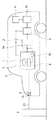
この発明の実施の形態1に係る充電システムの制御方法を説明する。図1に示すように、この実施の形態1で使用する充電システムは、PHV又はEVのようなモータ駆動可能な車両2に設けられた蓄電装置である例えばリチウムイオン二次電池等のバッテリ3と、バッテリ3を充電するための電力供給を行う給電装置4と、給電装置4から供給された電力をバッテリ3へ充電するための充電装置5とを備えている。
Embodiment 1
Embodiment 1 of the present invention will be described below with reference to the accompanying drawings.
A charging system control method according to Embodiment 1 of the present invention will be described. As shown in FIG. 1, the charging system used in the first embodiment includes a
車両2にはバッテリ3を充電するための充電装置5が設けられ、バッテリ3は充電装置5に電気的に接続されている。充電装置5には、バッテリ3の充電制御を行うための充電ECU6が設けられている。タイマ充電の時間管理を行うための充電タイマ7が充電装置5の内部に設けられ、充電ECU6と電気的に接続されている。また、バッテリ3の充電状態(SOC)すなわち電力残量を検出するSOCセンサ15が充電装置5の内部に設けられ、充電ECU6とバッテリ3とに電気的に接続されている。バッテリ3の近傍には、バッテリ温度Tを測定するための温度センサ14が設けられている。温度センサ14は充電装置5に電気的に接続されている。バッテリ3には、電力変換器9が電気的に接続されている。電力変換器9には、車両2を駆動させるためのモータ10が電気的に接続されている。電力変換器9は、モータ10の駆動時はバッテリ3から供給される電力を変換及び制御してモータ10に供給し、モータ10の回生運転によるモータ10の発電時には、モータ10から供給される電力を変換及び制御してバッテリ3に供給する。バッテリ3と、充電装置5と、電力変換器9と、モータ10とに、車両2の制御を行う車両ECU11が電気的に接続されている。
The vehicle 2 is provided with a charging device 5 for charging the
車両2に、車両2の外部に向けて開口したソケット状の受電口8が設けられており、受電口8は充電装置5に電気的に接続されている。また、給電装置4は、図示しない商用交流電源等の外部電源に接続されている。さらに、給電装置4には、先端にプラグ12を備えるコード13が設けられている。給電装置4からの電力供給により充電装置5がバッテリ3に対して充電を実施するために、プラグ12は車両2の受電口8に挿入されて接続されている。これにより、車両2と給電装置4がコード13によって接続されている。コード13は、給電装置4から供給される充電電力と、給電装置4と充電装置5との間でやり取りされる各種情報とを伝送することができる。
The vehicle 2 is provided with a socket-shaped power receiving port 8 that opens toward the outside of the vehicle 2, and the power receiving port 8 is electrically connected to the charging device 5. The power feeding device 4 is connected to an external power source such as a commercial AC power source (not shown). Furthermore, the power feeding device 4 is provided with a
次に、この発明の実施の形態1に係る充電システムの制御方法を説明する。
駐車されている車両2と給電装置4がコード13によって接続されている状態で、車両2の使用者が例えば車両2に設けられたタッチパネル等の図示しない入力装置で充電完了予定時刻をセットし、車両2のタイマ充電開始を指示すると、充電ECU6にタイマ充電開始の指示が充電完了予定時刻と共に入力される。充電ECU6は、充電タイマ7に充電完了時刻を送信する。充電ECU6は、SOCセンサ15を介してバッテリ3のSOCや、充電装置5とコード13を介して給電装置4から受信する給電装置4の充電電力供給能力の情報等を取得する。
Next, a charging system control method according to Embodiment 1 of the present invention will be described.
In a state where the parked vehicle 2 and the power feeding device 4 are connected by the
実施の形態1の充電システムにおいては、図2に示すように、充電開始後、バッテリ3の温度であるバッテリ温度Tが上昇するが、充電中のバッテリ温度Tの上限値としてTIが設定されており、充電開始後にバッテリ温度Tが充電時温度許容値初期値TIに達するまでは、バッテリ3への充電電力Wの値が給電装置4の充電電力供給能力に基づいた充電電力WAになるように充電制御を行う。バッテリ温度Tが充電時温度許容値初期値TIに達したら、給電装置4による充電電力を充電電力WAよりも低い充電電力制限値WCに変更する。ここで、充電電力制限値WCは、バッテリ温度Tが充電時温度許容値初期値TIに達した場合に、それ以上にバッテリ温度Tの上昇を防ぐための充電電力の値である。
In the charging system of the first embodiment, as shown in FIG. 2, after charging starts, battery temperature T, which is the temperature of
充電時温度許容値初期値TIは、実施の形態1の充電システム又は類似のシステムにおいて、充電中にバッテリ3を損傷させることがなく、さらに充電完了後に車両2を走行させた場合にすぐにバッテリ温度Tが走行時温度許容値TAに達しないように、走行時温度許容値TAに対して低い温度としている。続いて、図1に示すように、充電ECU6は充電電力WA(図2参照)と、バッテリ3のSOCと、現在のバッテリ温度T等の情報から、充電電力WAで充電を開始した後バッテリ3が満充電状態になるまで、すなわち充電開始から充電完了までの必要充電時間を計算する。充電タイマ7は、充電完了予定時刻と、必要充電時間から、充電開始予定時刻SC(図2参照)を計算して保持する。
In the charging system according to the first embodiment or a similar system, the charging-time temperature allowable value initial value TI does not damage the
充電タイマ7は、現在時刻と充電開始予定時刻SCとの照合を所定の周期で繰り返し、現在時刻が充電開始予定時刻SCに到達したら、充電ECU6に充電開始予定時刻到達通知を送信する。充電開始予定時刻到達通知を受信した充電ECU6は、給電装置4に充電電力WA(図2参照)の送出要求を送信する。充電電力WAの送出要求を受信した給電装置4は、充電装置5に対して充電電力WAを送出する。充電装置5は、充電電力WAでバッテリ3へ充電を行う。充電中に充電ECU6は、温度センサ14によってバッテリ温度Tをモニタし、SOCセンサ15によりバッテリ3のSOCをモニタする。図2に示すように、バッテリ3の温度が充電時温度許容値初期値TIに達した場合は、充電ECU6(図1参照)はバッテリ3を保護するために、給電装置4(図1参照)に充電電力制限値WCの送出要求を送信する。充電電力制限値WCの送出要求を受信した給電装置4は、充電装置5(図1参照)に対して充電電力制限値WCを送出する。充電装置5は、充電電力制限値WCでバッテリ3へ充電を行う。充電ECU6は、バッテリ3のSOCが満充電になれば、充電を停止する。さらに充電ECU6は給電装置4へ電力供給停止指示を送信する。電力供給停止指示を受信した給電装置4は、充電電力の供給を停止する。充電ECU6は充電電力の供給停止を確認したら、車両ECU11(図1参照)にタイマ充電終了の指示を送信することでタイマ充電が終了する。
The charging timer 7 repeats collation between the current time and the scheduled charging start time SC at a predetermined cycle. When the current time reaches the scheduled charging start time SC, the charging timer 7 transmits a scheduled charging start time arrival notification to the charging
タイマ充電終了後、充電タイマ7(図1参照)は今回の充電完了時刻SDを記録する。また、車両ECU11は、今回の充電完了時刻SD以降に車両2(図1参照)を走行開始した時に、充電タイマ7に車両走行開始通知を送信する。車両走行開始通知を受信した充電タイマ7は、その時の時刻である車両走行開始時刻SEと、充電完了時刻SDとの差を計算し、充電完了時刻SDから車両走行開始時刻SEまでの経過時間であり、充電システムのパラメータである充電完了後走行時間SFを計算して充電ECU6に送信する。充電ECU6は受信した充電完了後走行時間SFを記憶する。この車両2の走行時のバッテリ3の温度許容値は、充電時の充電時温度許容値初期値TIよりも高い走行時温度許容値TAである。ここまでで、初回のタイマ充電の充電制御を終了する。
After the timer charging is completed, the charging timer 7 (see FIG. 1) records the current charging completion time SD. Further, the
次に、少なくとも二回目以降のタイマ充電の充電制御について説明する。少なくとも二回目以降のタイマ充電において、充電ECU6はこれまでの充電制御にて記憶している充電完了後走行時間SFの値を合計し、充電完了後走行時間SFの合計値をこれまでに充電完了後走行時間SFを取得した回数で割る。これにより、充電ECU6はこれまでに取得した充電完了後走行時間SFの平均値である充電完了後走行時間平均値SG(図3参照)を得られる。
Next, at least the second and subsequent charging control for timer charging will be described. In at least the second and subsequent timer charging, the charging
図3に示すように、充電ECU6(図1参照)は、あらかじめ、充電完了後走行時間SFの標準値である充電完了後走行時間標準値SHを記憶している。ここで、充電完了後走行時間標準値SHは、実施の形態1と同一の、或いは類似した充電システムにおいての過去の実績から求められた値である。充電ECU6は、充電完了後走行時間標準値SHと充電完了後走行時間平均値SGとの差を計算し、充電完了後走行時間学習値SJとして記憶する。充電ECU6は、充電完了後走行時間学習値SJと、タイマ充電中のバッテリ3の上限温度である充電時温度許容値TLimとの関係を示した温度許容値曲線をあらかじめ保持しており、この温度許容値曲線をもとに、新たな充電時温度許容値TLimとして使用する補正後充電時温度許容値TBを決定する。すなわち、TLimを変更する。その後は、図2に示すように、補正後充電時温度許容値TBを使用して、一回目の充電と同様の充電制御を実施する。充電時温度許容値初期値TIとは異なる補正後充電時温度許容値TBを使用して充電制御を実施することで、車両2(図1参照)の使用状況に合わせた充電制御が行えるので充電効率が向上する。
As shown in FIG. 3, the charging ECU 6 (see FIG. 1) stores in advance a travel time standard value SH after completion of charging, which is a standard value of the travel time SF after completion of charging. Here, the travel time standard value SH after completion of charging is a value obtained from past performance in the same or similar charging system as in the first embodiment. The charging
このように、充電装置5は、バッテリ温度Tが充電時温度許容値TLim以下となるように充電装置5がバッテリ3へのタイマ充電を行い、タイマ充電完了後毎にバッテリ3へのタイマ充電完了時から車両2を使用するまでの車両2の状況から得られる充電完了後走行時間平均値SGを取得して、充電完了後走行時間標準値SHと、充電完了後走行時間平均値SGより充電完了後走行時間学習値SJを計算し、充電完了後走行時間学習値SJに基づいて新しい充電時温度許容値TLim以下になるように充電装置5がバッテリ3への充電を行い、充電完了後走行時間平均値SGより充電完了後走行時間学習値SJを計算することから蓄電装置5の温度が補正後充電時温度許容値TB以下になるように充電装置5がバッテリ3への充電を行うことを繰り返すことで、実際の充電完了時刻が充電完了予定時刻に対して遅れる事態の発生頻度を抑えることができる。
As described above, the charging device 5 performs the timer charging of the
実施の形態1では、車両2への充電完了後走行時間平均値SGと充電完了後走行時間標準値SHとの差を計算して計算結果を充電完了後走行時間学習値SJとして、補正後充電時温度許容値TBを求めていたが、充電完了後のバッテリ温度Tの変化を使用して、補正後充電時温度許容値TBを求めてもよい。 In the first embodiment, the difference between the travel time average value SG after completion of charging the vehicle 2 and the travel time standard value SH after completion of charging is calculated, and the calculated result is used as the travel time learned value SJ after completion of charging. Although the hourly temperature allowable value TB is obtained, the corrected chargeable temperature allowable value TB may be obtained using a change in the battery temperature T after the completion of charging.
具体的に説明すると、実施の形態1において、図2に示すように充電ECU6がバッテリ3への初回のタイマ充電終了時のバッテリ温度Tである充電完了時バッテリ温度TCを記録する。また、車両ECU11(図1参照)は、初回の充電完了時以降に車両2を走行開始した時に、充電ECU6(図1参照)に車両走行開始通知を送信する。車両走行開始通知を受信した充電ECU6は、その時のバッテリ温度Tである車両走行開始時バッテリ温度TDと、充電完了時バッテリ温度TCとの差を計算し、充電完了時から車両走行開始時までの温度変化であり、充電システムのパラメータである充電完了後バッテリ温度変化TEとして記憶する。ここまでで、初回のタイマ充電の充電制御を終了する。
Specifically, in the first embodiment, as shown in FIG. 2, the charging
次に、少なくとも二回目以降のタイマ充電の充電制御について説明する。少なくとも二回目以降のタイマ充電において、充電ECU6はこれまでの充電制御にて記憶している充電完了後バッテリ温度変化TEの値を合計し、充電完了後バッテリ温度変化TEの合計値をこれまでに充電完了後バッテリ温度変化TEを取得した回数で割る。これにより、充電ECU6はこれまでに取得した充電完了後バッテリ温度変化TEの平均値である充電完了後バッテリ温度変化平均値TF(図4参照)を得られる。図4に示すように、充電ECU6は、あらかじめ、充電完了後バッテリ温度変化TEの標準値である充電完了後バッテリ温度変化標準値TGを記憶している。ここで、充電完了後バッテリ温度変化標準値TGは、実施の形態1と同一の、或いは類似した充電システムにおいての過去の実績から求められた値である。充電ECU6は、充電完了後バッテリ温度変化標準値TGと充電完了後バッテリ温度変化平均値TFとの差を計算し、充電完了後バッテリ温度変化学習値TJとして記憶する。続いて、充電ECU6があらかじめ保持している、充電完了後バッテリ温度変化学習値TJと充電時温度許容値TLimとの関係を示した温度許容値曲線を基に、充電時温度許容値TLimの値である補正後充電時温度許容値TBを算出する。図2に示すように、その後は、補正後充電時温度許容値TBを使用して、一回目の充電と同様の充電制御を実施する。これにより、実施の形態1と同様の効果が得られる。
Next, at least the second and subsequent charging control for timer charging will be described. In at least the second and subsequent timer charging, the charging
実施の形態2
次に、この発明の実施の形態2に係る充電システムについて図1,図5〜図9を参照して説明する。この発明の実施の形態2に係る充電システムは、実施の形態1に対して電力制御の値をマップにより補正するものである。充電システムの構成は実施の形態1と同じである。
Embodiment 2
Next, a charging system according to Embodiment 2 of the present invention will be described with reference to FIGS. The charging system according to Embodiment 2 of the present invention corrects the value of power control with respect to Embodiment 1 using a map. The configuration of the charging system is the same as that of the first embodiment.
図1に示すように、充電ECU6は、SOCセンサ15を介してバッテリ3のSOCや、充電装置5とコード13とを介して給電装置4から受信する給電装置4の充電電力供給能力の情報等を取得するまでの動作は実施の形態1と同じである。
As shown in FIG. 1, the charging
充電ECU6は、充電時のバッテリ3への入力電力の許容値(上限)である充電電力許容値WDを保持している。充電電力許容値WDは、充電時のSOCとバッテリ温度Tとによって決定され、充電ECU6は図5に示すように、バッテリ3(図1参照)のSOCと、充電電力許容値WDとの関係を、バッテリ温度T毎に示した充電電力許容値曲線のマップとして有している。バッテリ3への充電は、現在のバッテリ温度Tに対応する充電電力許容値曲線において、SOCに対応する充電電力許容値WD以下の充電電力で充電する制御を行う。例えば、T=10℃且つSOC=10%とすると、充電電力許容値WDは、WEとなる。この実施の形態2の以下の説明における例では、充電電力許容値曲線としてT=10℃の場合の充電電力許容値曲線を使用する。また、この実施の形態2では充電電力として充電電力許容値WDと同じ電力を用いているが、実際には一般的に充電電力は充電電力許容値WD以下であればよく、充電電力許容値WDと同じ電力である必要はない。
The charging
図1に示すように、充電ECU6は、充電電力許容値曲線と、バッテリ3のSOCと、現在のバッテリ温度Tとから、バッテリ3があらかじめ決められた充電終了時のSOCであるSOC−Aになるまでの必要充電時間を計算する。ここでSOC−Aは、バッテリ3の満充電のSOCである。充電タイマ7は、充電完了予定時刻と、必要充電時間とから、充電開始予定時刻SCを計算して保持する。その後、充電ECU6が充電開始予定時刻到達通知を受信するまでは実施の形態1と同じである。充電ECU6が充電開始予定時刻到達通知を受信したら、充電ECU6は、給電装置4に一回目の充電の充電電力を送出する送出要求を送信する。充電装置5は、充電電力許容値WE(図5参照)に等しい充電電力でバッテリ3へ一回目のタイマ充電を開始する。
As shown in FIG. 1, the
図6に示すように、充電開始からの時間Sの経過によりSOCが増加していく。一般的に充電ECU6は、充電電力許容値曲線においてSOCに対応する充電電力許容値WD以下の充電電力で充電する制御を行うので、SOCが増加するにつれ充電電力許容値WDが減少し(図5参照)、その結果充電電力が減少する。この実施の形態2ではSOCが増加するにつれ充電電力許容値WEが減少する。充電が進みSOCがSOC−Aになったら充電ECU6は、充電を停止する。充電ECU6は、充電電力の供給停止を確認したら、車両ECU11(図1参照)にタイマ充電終了の指示を送信することで一回目のタイマ充電が終了する。
As shown in FIG. 6, the SOC increases with the passage of time S from the start of charging. In general, the charging
一回目のタイマ充電終了後、充電タイマ7(図1参照)は、一回目のタイマ充電の充電完了時刻SDを記録する。また、車両ECU11は、一回目のタイマ充電の充電完了時刻SD以降に車両2(図1参照)を走行開始した時に、充電タイマ7に車両走行開始通知を送信する。車両走行開始通知を受信した充電タイマ7は、その時の時刻である車両走行開始時刻SEと、充電完了時刻SDとの差を計算し、充電完了時刻SDから車両走行開始時刻SEまでの経過時間であり充電システムのパラメータである充電完了後走行時間SFを計算して充電ECU6に送信する。充電ECU6は、受信した充電完了後走行時間SFを記憶する。ここまでで、一回目のタイマ充電の充電制御を終了する。車両2が走行すると、SOCは減少する。
After the completion of the first timer charging, the charging timer 7 (see FIG. 1) records the charging completion time SD of the first timer charging. Further, the
次に、少なくとも二回目以降のタイマ充電の充電制御について説明する。少なくとも二回目以降のタイマ充電において、図7に示すように、充電ECU6は、実施の形態1と同様に、充電完了後走行時間標準値SHと充電完了後走行時間平均値SGとから充電完了後走行時間学習値SJを得る。充電ECU6は、充電電力許容値WD(図5参照)を車両2(図1参照)の使用状況に応じて補正するための充電完了後走行時間学習値SJと、充電電力補正係数WLimとの間の関係を示す電力補正値係数曲線のマップを保持している。実施の形態2では、充電完了後走行時間学習値SJに対するWLimはWF倍である。充電ECU6は、図6に示すように、SOCに対する充電電力許容値曲線上の充電電力許容値WEの値を縦軸方向にWF倍して新たな充電電力許容値曲線を作り、新たな充電電力許容値曲線でSOCに対する充電電力許容値曲線のマップを更新する。以降は、当該更新したマップを用いて、一回目の充電と同様の充電制御を実施することで、実施の形態2と同様に充電効率が向上する。
Next, at least the second and subsequent charging control for timer charging will be described. In at least the second and subsequent timer charging, as shown in FIG. 7, the charging
このように、充電開始時のバッテリ温度Tに対応する充電電力許容値曲線のマップを参照し、該充電電力許容値曲線においてSOCに対応する充電電力許容値WD以下の充電電力Wで充電する制御を行い、タイマ充電完了後毎に充電完了後走行時間SFを取得して、充電完了後走行時間SFの充電完了後走行時間平均値SGを算出し、充電完了後走行時間平均値SGより充電完了後走行時間学習値SJを計算し、充電完了後走行時間学習値SJに基づいてマップから、充電装置5が充電電力許容値WDをWF倍してSOCに対する充電電力許容値曲線のマップを新たな充電電力許容値曲線のマップに更新し、充電装置5がバッテリ3への充電を行うことを繰り返すことで、実施の形態1と同様の効果を得ることができる。
As described above, referring to the map of the allowable charge power curve corresponding to the battery temperature T at the start of charging, the control for charging with the charge power W equal to or lower than the allowable charge power WD corresponding to the SOC in the allowable charge power curve. The charging time after completion of charging is obtained every time the timer charging is completed, the driving time average value SG after the charging is completed for the driving time SF after charging is completed, and the charging is completed from the driving time average value SG after the charging is completed. A post travel time learning value SJ is calculated, and from the map based on the post travel completion travel time learned value SJ, the charging device 5 multiplies the charge power allowable value WD by WF and a new charge power allowable value curve map for the SOC is newly created. The same effect as in the first embodiment can be obtained by updating the charging power allowable value curve map and repeating charging of the
実施の形態2では、車両2への充電完了後走行時間平均値SGと充電完了後走行時間標準値SHとの差を計算して計算結果を充電完了後走行時間学習値SJとして、充電電力補正係数WLimを求めていたが、充電完了後のバッテリ温度Tの変化を使用して、充電電力補正係数WLimを求めてもよい。 In the second embodiment, the charging power correction is performed by calculating the difference between the travel time average value SG after completion of charging the vehicle 2 and the travel time standard value SH after completion of charging as the travel time learned value SJ after completion of charging. Although the coefficient WLim has been obtained, the charging power correction coefficient WLim may be obtained using a change in the battery temperature T after the completion of charging.
具体的に説明すると、図8に示すように、実施の形態2において、実施の形態1の変形例と同様に、充電ECU6(図1参照)が充電完了時バッテリ温度TCを記録する。また、車両ECU11(図1参照)は、初回の充電完了時以降に車両2(図1参照)を走行開始した時に、充電ECU6に車両走行開始通知を送信する。車両走行開始通知を受信した充電ECU6は、その時のバッテリ温度Tである車両走行開始時バッテリ温度TDと、充電完了時バッテリ温度TCとの差を計算し、充電完了後バッテリ温度変化TEとして記憶する。ここまでで、初回のタイマ充電の充電制御を終了する。
Specifically, as shown in FIG. 8, in the second embodiment, as in the modification of the first embodiment, the charging ECU 6 (see FIG. 1) records the battery temperature TC at the completion of charging. Further, the vehicle ECU 11 (see FIG. 1) transmits a vehicle travel start notification to the charging
次に、少なくとも二回目以降のタイマ充電の充電制御について説明する。実施の形態1の変形例と同様に、少なくとも二回目以降のタイマ充電において、図9に示すように、実施の形態1と同様に、これまでに取得した充電完了後バッテリ温度変化TEの平均値である充電完了後バッテリ温度変化平均値TFを得る。そして充電ECU6は、充電完了後バッテリ温度変化標準値TGと充電完了後バッテリ温度変化平均値TFとの差を計算し、充電完了後バッテリ温度変化学習値TJとして記憶する。続いて、充電ECU6(図1参照)は、保持している充電電力許容値WDを車両2(図1参照)の使用状況に応じて補正するための充電完了後バッテリ温度変化学習値TJと、充電電力補正係数WLimとの間の関係を示す電力補正係数曲線を基に、充電完了後バッテリ温度変化学習値TJに対する新たな充電電力補正係数WLimを得、その値はWF倍である。充電ECU6(図1参照)が、充電電力許容値WDをWF倍して、SOCに対する充電電力許容値曲線のマップを更新する。以降は、当該更新したマップを用いて、一回目の充電と同様の充電制御を実施することで、実施の形態1と同様に充電効率が向上する。
Next, at least the second and subsequent charging control for timer charging will be described. As in the modification of the first embodiment, in at least the second and subsequent timer charging, as shown in FIG. 9, the average value of the battery temperature change TE after completion of charging obtained so far, as in the first embodiment. The battery temperature change average value TF is obtained after the completion of charging. Then, the charging
実施の形態1及び2では、二回目以降のタイマ充電について、充電ECU6はこれまでの充電制御にて記憶している充電完了後走行時間SFから充電完了後走行時間平均値SGを求めていたが、例えば五回目以降など、一回目以外の任意のタイマ充電回数以降から、充電完了後走行時間平均値SGを求めるようにしてもよい。また、充電ECU6は毎回充電毎など任意の回数毎に充電完了後走行時間平均値SGを求めるのではなく、例えば充電五回毎に充電完了後走行時間平均値SGを求めるようにしてもよい。さらに、充電ECU6は毎回充電毎の充電完了後走行時間SFを全て記憶するのではなく、例えば最近の充電五回などの任意の回数の充電完了後走行時間SFを記憶し、それより古い充電時の充電完了後走行時間SFの記憶情報を破棄するようにしてもよい。同様に、実施の形態1の変形例及び2の変形例では、充電ECU6はこれまでの充電制御にて記憶している充電完了後バッテリ温度変化TEから充電完了後バッテリ温度変化平均値TFを求めていたが、例えば五回目以降など、一回目以外の任意のタイマ充電回数以降から、充電完了後バッテリ温度変化平均値TFを求めるようにしてもよい。また、充電ECU6は毎回充電毎に充電完了後バッテリ温度変化平均値TFを求めるのではなく、例えば充電五回毎など任意の回数毎に充電完了後バッテリ温度変化平均値TFを求めるようにしてもよい。さらに、充電ECU6は毎回充電毎の充電完了後バッテリ温度変化平均値TFを全て記憶するのではなく、例えば最近の充電五回などの任意の回数の充電完了後バッテリ温度変化平均値TFを記憶し、それより古い充電時の充電完了後バッテリ温度変化平均値TFの記憶情報を破棄するようにしてもよい。
In the first and second embodiments, for the second and subsequent timer charging, the charging
実施の形態1及び2では、充電完了後走行時間標準値SHと充電完了後走行時間平均値SGとの差を計算して(SH−SG)を充電完了後走行時間学習値SJとしていたが、充電完了後走行時間平均値SGの値をそのまま充電完了後走行時間学習値SJとして使用してもよい(つまり、充電完了後走行時間標準値SH=0に相当する)。この場合、図3及び図7における横軸である充電完了後走行時間学習値SJは、左端が0となり常に正の値をとる。同様に、実施の形態1の変形例及び2の変形例では、充電完了後バッテリ温度変化標準値TGと充電完了後バッテリ温度変化平均値TFとの差を計算して充電完了後バッテリ温度変化学習値TJとしていたが、充電完了後バッテリ温度変化平均値TFの値をそのまま充電完了後バッテリ温度変化学習値TJとして使用してもよい(つまり、充電完了後バッテリ温度変化標準値TG=0に相当する)。この場合、図4及び図9における横軸である充電完了後バッテリ温度変化学習値TJは左端が0となり常に正の値をとる。 In the first and second embodiments, the difference between the travel time standard value SH after completion of charging and the travel time average value SG after completion of charging is calculated as (SH-SG) as the travel time learned value SJ after completion of charging. The value of the travel time average value SG after completion of charging may be used as it is as the travel time learning value SJ after completion of charge (that is, the travel time standard value SH = 0 after completion of charge). In this case, the post-charging travel time learning value SJ, which is the horizontal axis in FIGS. 3 and 7, is 0 at the left end and always takes a positive value. Similarly, in the first and second modifications, the difference between the battery temperature change standard value TG after completion of charging and the battery temperature change average value TF after completion of charging is calculated to calculate the battery temperature change after completion of charging. Although the value TJ was used, the value of the battery temperature change average value TF after completion of charging may be used as it is as the battery temperature change learning value TJ after completion of charging (that is, equivalent to the battery temperature change standard value TG = 0 after completion of charging). Do). In this case, the battery temperature change learning value TJ after completion of charging, which is the horizontal axis in FIGS. 4 and 9, is 0 at the left end and always takes a positive value.
実施の形態1及び2では、充電システムはコード13を介した有線での充電及び給電装置4と充電装置5との情報の通信を行うシステムであるが、非接触充電や非接触通信を利用した充電システムであってもよい。また、使用者が充電開始を充電システムに指示するときに例えば車両2に設けられたタッチパネル等の図示しない入力装置を使用したが、例えば車両2に設けられた音声入力装置や、車両2の外部に設けられた携帯端末等の任意の入力装置を使用してもよい。また、入力装置は車両2に設けられたが、給電装置4に設けてもよく、或いは、屋内等に設置される遠隔操作装置に設けられてもよい。
In the first and second embodiments, the charging system is a system that performs wired communication via the
実施の形態1及び2では、バッテリ3へのタイマ充電完了は満充電になった時であったが、満充電以外の任意のSOCであってもよい。
In the first and second embodiments, the completion of timer charging to the
実施の形態1及び2では、充電完了後走行時間平均値SGと充電完了後走行時間標準値SHとの差をとって充電完了後走行時間学習値SJを算出していたが、充電完了後走行時間を一回だけ取得して平均せずに充電完了後走行時間標準値SHとの差をとって充電完了後走行時間学習値SJを求めてもよい。同様に実施の形態1及び2では、充電完了後バッテリ温度変化平均値TFと充電完了後バッテリ温度変化標準値TGとの差をとって充電完了後バッテリ温度変化学習値TJを算出していたが、充電完了後バッテリ温度を一回だけ取得して平均せずに充電完了後バッテリ温度変化標準値TGとの差をとって充電完了後バッテリ温度変化学習値TJを算出してもよい。 In the first and second embodiments, the travel time learning value SJ after completion of charging is calculated by taking the difference between the travel time average value SG after completion of charging and the travel time standard value SH after completion of charging. The travel time learning value SJ after completion of charging may be obtained by taking the difference from the travel time standard value SH after completion of charging without acquiring the time only once and averaging. Similarly, in Embodiments 1 and 2, the battery temperature change learning value TJ after charging is calculated by taking the difference between the battery temperature change average value TF after charging and the battery temperature change standard value TG after charging. Alternatively, the battery temperature change learning value TJ after completion of charging may be calculated by taking the difference from the battery temperature change standard value TG after completion of charging without obtaining the battery temperature once after completion of charging and averaging.
実施の形態1及び2では、充電タイマ7は充電装置5に設けられたが、給電装置4に設けられてもよく、或いは、屋内等に設置される遠隔操作装置に設けられてもよい。充電装置5に充電タイマ7が無い場合は、代わりに、充電完了時刻SD、車両走行開始時刻SEを取得するタイマ部が充電装置5に設けられるのが好ましい。また、充電タイマ7又はタイマ部が取得した充電完了時刻SD、車両走行開始時刻SEを充電ECU6へ送信し、充電ECUが充電完了後走行時間SFを計算してもよい。また、充電ECU6が充電タイマ7又はタイマ部の機能を備えてもよい。
In Embodiments 1 and 2, the charging timer 7 is provided in the charging device 5, but it may be provided in the power feeding device 4, or may be provided in a remote control device installed indoors or the like. When the charging device 5 does not have the charging timer 7, it is preferable that the charging device 5 is provided with a timer unit that acquires the charging completion time SD and the vehicle travel start time SE instead. Alternatively, the charge completion time SD and the vehicle travel start time SE acquired by the charge timer 7 or the timer unit may be transmitted to the
2 車両、3 バッテリ(蓄電装置)、5 充電装置、7 充電タイマ。 2 vehicle, 3 battery (power storage device), 5 charging device, 7 charging timer.
Claims (7)
前記車両に設けられた蓄電装置と、
前記車両に設けられ、前記蓄電装置に充電を行う充電装置と、
前記充電装置による前記蓄電装置への充電時間を管理する充電タイマと
を備え、前記充電装置による前記蓄電装置への充電を、あらかじめ設定された充電完了時刻に完了するタイマ充電を行う充電方法であって、
前記充電装置は、前記蓄電装置への充電中における前記蓄電装置の温度の上限である充電時温度許容値を保持し、
前記蓄電装置の温度が前記充電時温度許容値以下となるように、前記充電装置が前記蓄電装置への充電を行う第1のステップと、
タイマ充電完了後毎に、前記蓄電装置へのタイマ充電完了時から前記車両を使用するまでの前記車両の状況から得られるパラメータを取得して、前記パラメータのあらかじめ設定されている標準値と前記パラメータとから求められる学習値を計算する第2のステップと、
前記学習値に基づいて新しい充電時温度許容値が決定される第3のステップと、
前記蓄電装置の温度が前記新しい充電時温度許容値以下になるように前記充電装置が前記蓄電装置への充電を行う第4のステップと、
前記第2のステップから前記第4のステップを繰り返す第5のステップと
を含む充電方法。 A vehicle,
A power storage device provided in the vehicle;
A charging device provided in the vehicle for charging the power storage device;
A charging timer for managing charging time of the power storage device by the charging device, and charging the power storage device by the charging device at a preset charging completion time. And
The charging device holds a charging temperature allowable value that is an upper limit of the temperature of the power storage device during charging of the power storage device,
A first step in which the charging device charges the power storage device such that a temperature of the power storage device is equal to or lower than a temperature allowable value during charging;
Each time after completion of timer charging, a parameter obtained from the situation of the vehicle from completion of timer charging to the power storage device until use of the vehicle is obtained, and a preset standard value of the parameter and the parameter are obtained. A second step of calculating a learning value obtained from
A third step in which a new chargeable temperature tolerance is determined based on the learned value;
A fourth step in which the charging device charges the power storage device such that the temperature of the power storage device is equal to or less than the new charging temperature limit;
And a fifth step of repeating the fourth step from the second step.
前記車両に設けられた蓄電装置と、
前記車両に設けられ、前記蓄電装置に充電を行う充電装置と、
前記充電装置による前記蓄電装置への充電時間を管理する充電タイマと
を備え、前記充電装置による前記蓄電装置への充電を、あらかじめ設定された充電完了時刻に完了するタイマ充電を行う充電方法であって、
前記充電装置は、前記蓄電装置への充電中における前記蓄電装置へ入力される電力の上限である充電電力許容値を保持し、
前記蓄電装置の充電電力が前記充電電力許容値以下となるように、前記充電装置が前記蓄電装置への充電を前記充電電力許容値以下の電力で行う第1のステップと、
タイマ充電完了後毎に、前記蓄電装置へのタイマ充電完了時から前記車両を使用するまでの前記車両の状況から得られるパラメータを取得して、前記パラメータのあらかじめ設定されている標準値と前記パラメータとから求められる学習値を計算する第2のステップと、
前記学習値に基づいて新しい充電電力許容値が決定される第3のステップと、
前記蓄電装置の充電電力が前記新しい充電電力許容値以下となるように、前記充電装置が前記蓄電装置への充電を行う第4のステップと、
前記第2のステップから前記第4のステップを繰り返す第5のステップと
を含む充電方法。 A vehicle,
A power storage device provided in the vehicle;
A charging device provided in the vehicle for charging the power storage device;
A charging timer for managing charging time of the power storage device by the charging device, and charging the power storage device by the charging device at a preset charging completion time. And
The charging device holds a charge power allowable value that is an upper limit of power input to the power storage device during charging of the power storage device,
A first step in which the charging device performs charging of the power storage device with power less than or equal to the charge power allowable value such that charge power of the power storage device is less than or equal to the charge power allowable value;
Each time after completion of timer charging, a parameter obtained from the situation of the vehicle from completion of timer charging to the power storage device until use of the vehicle is obtained, and a preset standard value of the parameter and the parameter are obtained. A second step of calculating a learning value obtained from
A third step in which a new charge power allowance is determined based on the learned value;
A fourth step in which the charging device charges the power storage device such that the charging power of the power storage device is less than or equal to the new charge power allowable value;
And a fifth step of repeating the fourth step from the second step.
前記充電電力許容値を決定するマップを補正するための、前記学習値から充電電力補正係数を決定するマップと
をさらに備え、
前記第3のステップにおいて、前記学習値から前記充電電力補正係数を決定するマップに基づいて前記充電電力補正係数を求め、前記充電電力許容値を決定するためのマップを前記充電電力補正係数で乗算して補正し、補正された前記充電電力許容値を決定するためのマップに基づいて新しい充電電力許容値を決定する、請求項3に記載の充電方法。 A map for determining the charge power allowable value with respect to the remaining power of the power storage device;
A map for determining a charging power correction coefficient from the learning value for correcting a map for determining the allowable charging power value;
In the third step, the charging power correction coefficient is obtained based on a map for determining the charging power correction coefficient from the learned value, and a map for determining the charging power allowable value is multiplied by the charging power correction coefficient. The charging method according to claim 3, wherein a new charging power allowable value is determined based on a map for determining the corrected charging power allowable value.
Priority Applications (1)
| Application Number | Priority Date | Filing Date | Title |
|---|---|---|---|
| JP2014045033A JP6098552B2 (en) | 2014-03-07 | 2014-03-07 | Charging method |
Applications Claiming Priority (1)
| Application Number | Priority Date | Filing Date | Title |
|---|---|---|---|
| JP2014045033A JP6098552B2 (en) | 2014-03-07 | 2014-03-07 | Charging method |
Publications (2)
| Publication Number | Publication Date |
|---|---|
| JP2015171244A JP2015171244A (en) | 2015-09-28 |
| JP6098552B2 true JP6098552B2 (en) | 2017-03-22 |
Family
ID=54203531
Family Applications (1)
| Application Number | Title | Priority Date | Filing Date |
|---|---|---|---|
| JP2014045033A Expired - Fee Related JP6098552B2 (en) | 2014-03-07 | 2014-03-07 | Charging method |
Country Status (1)
| Country | Link |
|---|---|
| JP (1) | JP6098552B2 (en) |
Families Citing this family (1)
| Publication number | Priority date | Publication date | Assignee | Title |
|---|---|---|---|---|
| CN113978311B (en) * | 2021-10-15 | 2024-05-17 | 潍柴动力股份有限公司 | Battery temperature correction method and device and electronic equipment |
Family Cites Families (2)
| Publication number | Priority date | Publication date | Assignee | Title |
|---|---|---|---|---|
| JP4049959B2 (en) * | 1999-11-11 | 2008-02-20 | 本田技研工業株式会社 | Battery charging method |
| JP2002233070A (en) * | 2000-11-28 | 2002-08-16 | Honda Motor Co Ltd | Battery charger |
-
2014
- 2014-03-07 JP JP2014045033A patent/JP6098552B2/en not_active Expired - Fee Related
Also Published As
| Publication number | Publication date |
|---|---|
| JP2015171244A (en) | 2015-09-28 |
Similar Documents
| Publication | Publication Date | Title |
|---|---|---|
| JP6597684B2 (en) | Vehicle, vehicle control method, and charging system | |
| US9487102B2 (en) | Charging method of green car | |
| EP2946976A3 (en) | Power supply control device | |
| JP2015171208A (en) | Control method of charging system | |
| CN102928790B (en) | Battery status method for supervising and watch-dog | |
| RU2016144986A (en) | BATTERY SYSTEM | |
| WO2013051151A1 (en) | Vehicle charging system and method for charging vehicle | |
| JP2015139346A (en) | Driving distance calculation system | |
| JP6350442B2 (en) | Charge control system | |
| WO2015001751A1 (en) | Vehicle storage battery management device, vehicle power unit, and vehicle storage battery management method | |
| JP6213709B2 (en) | Hybrid vehicle engine start control device | |
| WO2020149102A1 (en) | Charging system and method for controlling charging system | |
| JP2015233366A (en) | Vehicle power supply | |
| US20200295590A1 (en) | Charge control device | |
| CN108215812A (en) | The method and device of vehicle start under a kind of low temperature | |
| JP2019154167A (en) | Charging system of electric vehicle | |
| JP2016208639A (en) | vehicle | |
| JP2018102084A (en) | Charge control device | |
| JP6098552B2 (en) | Charging method | |
| JP6304010B2 (en) | Secondary battery heating system | |
| JP6127855B2 (en) | Charging system control device and charging system control method | |
| KR101481215B1 (en) | An electric vehicle, an electric vehicle charging system and method for charging electric vehicle | |
| KR20140031500A (en) | System and method for controlling charging of electric vehicles | |
| JP6724807B2 (en) | Charging system | |
| JP6024632B2 (en) | Vehicle charging system and vehicle charging control method |
Legal Events
| Date | Code | Title | Description |
|---|---|---|---|
| A621 | Written request for application examination |
Free format text: JAPANESE INTERMEDIATE CODE: A621 Effective date: 20160510 |
|
| A977 | Report on retrieval |
Free format text: JAPANESE INTERMEDIATE CODE: A971007 Effective date: 20170119 |
|
| TRDD | Decision of grant or rejection written | ||
| A01 | Written decision to grant a patent or to grant a registration (utility model) |
Free format text: JAPANESE INTERMEDIATE CODE: A01 Effective date: 20170124 |
|
| A61 | First payment of annual fees (during grant procedure) |
Free format text: JAPANESE INTERMEDIATE CODE: A61 Effective date: 20170206 |
|
| R151 | Written notification of patent or utility model registration |
Ref document number: 6098552 Country of ref document: JP Free format text: JAPANESE INTERMEDIATE CODE: R151 |
|
| LAPS | Cancellation because of no payment of annual fees |