WO2013051151A1 - Vehicle charging system and method for charging vehicle - Google Patents
Vehicle charging system and method for charging vehicle Download PDFInfo
- Publication number
- WO2013051151A1 WO2013051151A1 PCT/JP2011/073205 JP2011073205W WO2013051151A1 WO 2013051151 A1 WO2013051151 A1 WO 2013051151A1 JP 2011073205 W JP2011073205 W JP 2011073205W WO 2013051151 A1 WO2013051151 A1 WO 2013051151A1
- Authority
- WO
- WIPO (PCT)
- Prior art keywords
- charging
- storage device
- power storage
- vehicle
- state
- Prior art date
Links
Images


Classifications
-
- B—PERFORMING OPERATIONS; TRANSPORTING
- B60—VEHICLES IN GENERAL
- B60L—PROPULSION OF ELECTRICALLY-PROPELLED VEHICLES; SUPPLYING ELECTRIC POWER FOR AUXILIARY EQUIPMENT OF ELECTRICALLY-PROPELLED VEHICLES; ELECTRODYNAMIC BRAKE SYSTEMS FOR VEHICLES IN GENERAL; MAGNETIC SUSPENSION OR LEVITATION FOR VEHICLES; MONITORING OPERATING VARIABLES OF ELECTRICALLY-PROPELLED VEHICLES; ELECTRIC SAFETY DEVICES FOR ELECTRICALLY-PROPELLED VEHICLES
- B60L53/00—Methods of charging batteries, specially adapted for electric vehicles; Charging stations or on-board charging equipment therefor; Exchange of energy storage elements in electric vehicles
- B60L53/20—Methods of charging batteries, specially adapted for electric vehicles; Charging stations or on-board charging equipment therefor; Exchange of energy storage elements in electric vehicles characterised by converters located in the vehicle
-
- B—PERFORMING OPERATIONS; TRANSPORTING
- B60—VEHICLES IN GENERAL
- B60L—PROPULSION OF ELECTRICALLY-PROPELLED VEHICLES; SUPPLYING ELECTRIC POWER FOR AUXILIARY EQUIPMENT OF ELECTRICALLY-PROPELLED VEHICLES; ELECTRODYNAMIC BRAKE SYSTEMS FOR VEHICLES IN GENERAL; MAGNETIC SUSPENSION OR LEVITATION FOR VEHICLES; MONITORING OPERATING VARIABLES OF ELECTRICALLY-PROPELLED VEHICLES; ELECTRIC SAFETY DEVICES FOR ELECTRICALLY-PROPELLED VEHICLES
- B60L58/00—Methods or circuit arrangements for monitoring or controlling batteries or fuel cells, specially adapted for electric vehicles
- B60L58/10—Methods or circuit arrangements for monitoring or controlling batteries or fuel cells, specially adapted for electric vehicles for monitoring or controlling batteries
- B60L58/12—Methods or circuit arrangements for monitoring or controlling batteries or fuel cells, specially adapted for electric vehicles for monitoring or controlling batteries responding to state of charge [SoC]
- B60L58/15—Preventing overcharging
-
- G—PHYSICS
- G05—CONTROLLING; REGULATING
- G05F—SYSTEMS FOR REGULATING ELECTRIC OR MAGNETIC VARIABLES
- G05F1/00—Automatic systems in which deviations of an electric quantity from one or more predetermined values are detected at the output of the system and fed back to a device within the system to restore the detected quantity to its predetermined value or values, i.e. retroactive systems
- G05F1/66—Regulating electric power
-
- H—ELECTRICITY
- H01—ELECTRIC ELEMENTS
- H01M—PROCESSES OR MEANS, e.g. BATTERIES, FOR THE DIRECT CONVERSION OF CHEMICAL ENERGY INTO ELECTRICAL ENERGY
- H01M10/00—Secondary cells; Manufacture thereof
- H01M10/42—Methods or arrangements for servicing or maintenance of secondary cells or secondary half-cells
- H01M10/44—Methods for charging or discharging
-
- H—ELECTRICITY
- H01—ELECTRIC ELEMENTS
- H01M—PROCESSES OR MEANS, e.g. BATTERIES, FOR THE DIRECT CONVERSION OF CHEMICAL ENERGY INTO ELECTRICAL ENERGY
- H01M10/00—Secondary cells; Manufacture thereof
- H01M10/42—Methods or arrangements for servicing or maintenance of secondary cells or secondary half-cells
- H01M10/46—Accumulators structurally combined with charging apparatus
-
- H—ELECTRICITY
- H01—ELECTRIC ELEMENTS
- H01M—PROCESSES OR MEANS, e.g. BATTERIES, FOR THE DIRECT CONVERSION OF CHEMICAL ENERGY INTO ELECTRICAL ENERGY
- H01M10/00—Secondary cells; Manufacture thereof
- H01M10/42—Methods or arrangements for servicing or maintenance of secondary cells or secondary half-cells
- H01M10/48—Accumulators combined with arrangements for measuring, testing or indicating the condition of cells, e.g. the level or density of the electrolyte
-
- H—ELECTRICITY
- H02—GENERATION; CONVERSION OR DISTRIBUTION OF ELECTRIC POWER
- H02J—CIRCUIT ARRANGEMENTS OR SYSTEMS FOR SUPPLYING OR DISTRIBUTING ELECTRIC POWER; SYSTEMS FOR STORING ELECTRIC ENERGY
- H02J7/00—Circuit arrangements for charging or depolarising batteries or for supplying loads from batteries
- H02J7/007—Regulation of charging or discharging current or voltage
- H02J7/0071—Regulation of charging or discharging current or voltage with a programmable schedule
-
- B—PERFORMING OPERATIONS; TRANSPORTING
- B60—VEHICLES IN GENERAL
- B60L—PROPULSION OF ELECTRICALLY-PROPELLED VEHICLES; SUPPLYING ELECTRIC POWER FOR AUXILIARY EQUIPMENT OF ELECTRICALLY-PROPELLED VEHICLES; ELECTRODYNAMIC BRAKE SYSTEMS FOR VEHICLES IN GENERAL; MAGNETIC SUSPENSION OR LEVITATION FOR VEHICLES; MONITORING OPERATING VARIABLES OF ELECTRICALLY-PROPELLED VEHICLES; ELECTRIC SAFETY DEVICES FOR ELECTRICALLY-PROPELLED VEHICLES
- B60L2250/00—Driver interactions
- B60L2250/14—Driver interactions by input of vehicle departure time
-
- H—ELECTRICITY
- H01—ELECTRIC ELEMENTS
- H01M—PROCESSES OR MEANS, e.g. BATTERIES, FOR THE DIRECT CONVERSION OF CHEMICAL ENERGY INTO ELECTRICAL ENERGY
- H01M10/00—Secondary cells; Manufacture thereof
- H01M10/42—Methods or arrangements for servicing or maintenance of secondary cells or secondary half-cells
- H01M10/425—Structural combination with electronic components, e.g. electronic circuits integrated to the outside of the casing
- H01M2010/4271—Battery management systems including electronic circuits, e.g. control of current or voltage to keep battery in healthy state, cell balancing
-
- H—ELECTRICITY
- H01—ELECTRIC ELEMENTS
- H01M—PROCESSES OR MEANS, e.g. BATTERIES, FOR THE DIRECT CONVERSION OF CHEMICAL ENERGY INTO ELECTRICAL ENERGY
- H01M2220/00—Batteries for particular applications
- H01M2220/20—Batteries in motive systems, e.g. vehicle, ship, plane
-
- Y—GENERAL TAGGING OF NEW TECHNOLOGICAL DEVELOPMENTS; GENERAL TAGGING OF CROSS-SECTIONAL TECHNOLOGIES SPANNING OVER SEVERAL SECTIONS OF THE IPC; TECHNICAL SUBJECTS COVERED BY FORMER USPC CROSS-REFERENCE ART COLLECTIONS [XRACs] AND DIGESTS
- Y02—TECHNOLOGIES OR APPLICATIONS FOR MITIGATION OR ADAPTATION AGAINST CLIMATE CHANGE
- Y02E—REDUCTION OF GREENHOUSE GAS [GHG] EMISSIONS, RELATED TO ENERGY GENERATION, TRANSMISSION OR DISTRIBUTION
- Y02E60/00—Enabling technologies; Technologies with a potential or indirect contribution to GHG emissions mitigation
- Y02E60/10—Energy storage using batteries
-
- Y—GENERAL TAGGING OF NEW TECHNOLOGICAL DEVELOPMENTS; GENERAL TAGGING OF CROSS-SECTIONAL TECHNOLOGIES SPANNING OVER SEVERAL SECTIONS OF THE IPC; TECHNICAL SUBJECTS COVERED BY FORMER USPC CROSS-REFERENCE ART COLLECTIONS [XRACs] AND DIGESTS
- Y02—TECHNOLOGIES OR APPLICATIONS FOR MITIGATION OR ADAPTATION AGAINST CLIMATE CHANGE
- Y02T—CLIMATE CHANGE MITIGATION TECHNOLOGIES RELATED TO TRANSPORTATION
- Y02T10/00—Road transport of goods or passengers
- Y02T10/60—Other road transportation technologies with climate change mitigation effect
- Y02T10/70—Energy storage systems for electromobility, e.g. batteries
-
- Y—GENERAL TAGGING OF NEW TECHNOLOGICAL DEVELOPMENTS; GENERAL TAGGING OF CROSS-SECTIONAL TECHNOLOGIES SPANNING OVER SEVERAL SECTIONS OF THE IPC; TECHNICAL SUBJECTS COVERED BY FORMER USPC CROSS-REFERENCE ART COLLECTIONS [XRACs] AND DIGESTS
- Y02—TECHNOLOGIES OR APPLICATIONS FOR MITIGATION OR ADAPTATION AGAINST CLIMATE CHANGE
- Y02T—CLIMATE CHANGE MITIGATION TECHNOLOGIES RELATED TO TRANSPORTATION
- Y02T10/00—Road transport of goods or passengers
- Y02T10/60—Other road transportation technologies with climate change mitigation effect
- Y02T10/7072—Electromobility specific charging systems or methods for batteries, ultracapacitors, supercapacitors or double-layer capacitors
-
- Y—GENERAL TAGGING OF NEW TECHNOLOGICAL DEVELOPMENTS; GENERAL TAGGING OF CROSS-SECTIONAL TECHNOLOGIES SPANNING OVER SEVERAL SECTIONS OF THE IPC; TECHNICAL SUBJECTS COVERED BY FORMER USPC CROSS-REFERENCE ART COLLECTIONS [XRACs] AND DIGESTS
- Y02—TECHNOLOGIES OR APPLICATIONS FOR MITIGATION OR ADAPTATION AGAINST CLIMATE CHANGE
- Y02T—CLIMATE CHANGE MITIGATION TECHNOLOGIES RELATED TO TRANSPORTATION
- Y02T90/00—Enabling technologies or technologies with a potential or indirect contribution to GHG emissions mitigation
- Y02T90/10—Technologies relating to charging of electric vehicles
- Y02T90/12—Electric charging stations
-
- Y—GENERAL TAGGING OF NEW TECHNOLOGICAL DEVELOPMENTS; GENERAL TAGGING OF CROSS-SECTIONAL TECHNOLOGIES SPANNING OVER SEVERAL SECTIONS OF THE IPC; TECHNICAL SUBJECTS COVERED BY FORMER USPC CROSS-REFERENCE ART COLLECTIONS [XRACs] AND DIGESTS
- Y02—TECHNOLOGIES OR APPLICATIONS FOR MITIGATION OR ADAPTATION AGAINST CLIMATE CHANGE
- Y02T—CLIMATE CHANGE MITIGATION TECHNOLOGIES RELATED TO TRANSPORTATION
- Y02T90/00—Enabling technologies or technologies with a potential or indirect contribution to GHG emissions mitigation
- Y02T90/10—Technologies relating to charging of electric vehicles
- Y02T90/14—Plug-in electric vehicles
Definitions
- the present invention relates to a vehicle charging system and a vehicle charging method, and more particularly to a charging system and a charging method for charging a vehicle equipped with a power storage device from the outside of the vehicle.
- a vehicle such as an electric vehicle, a hybrid vehicle, and a fuel cell vehicle that can generate a vehicle driving force by an electric motor is equipped with a power storage device that stores electric power for driving the electric motor.
- power is supplied from the power storage device to the electric motor when starting or accelerating to generate vehicle driving force, while electric power generated by regenerative braking of the electric motor during downhill driving or deceleration is used.
- Supply to power storage device is used.
- a configuration has been proposed in which a power storage device can be charged (hereinafter also simply referred to as “external charging”) by being electrically connected to an external power source such as a commercial power source.
- external charging a power storage device can be charged
- the charging of the power storage device ends immediately before the scheduled charging end time.
- a vehicle having a timer charging function There is a vehicle having a timer charging function.
- Patent Document 1 discloses a storage battery charge control device for an electric vehicle that controls a charger that charges the storage battery for the electric vehicle.
- the charging control device described in Patent Document 1 when the power supply is connected by inserting a power plug provided in the charger into the power jack prior to charging, the power supply voltage connected to the charger is set. A value is detected.
- Charging time is calculated. Further, based on the set boarding scheduled time and the calculated required charging time, a charging start time for ending charging at the scheduled boarding time is calculated. Then, when the charging start time comes, charging is started by the charging current value.
- Patent Document 1 In the configuration described in Patent Document 1 described above, charging of the power storage device is not started until the charging start time calculated based on the required charging time is reached. Therefore, in Patent Document 1, when the user wants to use the vehicle at a time earlier than the set scheduled boarding time, there is a possibility that electric power sufficient for traveling of the vehicle is not stored in the power storage device. In such a situation, the drivability of the vehicle may be reduced due to the lack of output power from the power storage device. As a result, the convenience of the vehicle (user convenience) may be impaired.
- the present invention has been made to solve such a problem, and an object thereof is to provide a vehicle charging system capable of improving the drivability and convenience of the vehicle.
- a vehicle charging system for controlling charging of a power storage device mounted on a vehicle, the charging configured to be able to convert electric power from an external power source into charging power for the power storage device.
- An input unit for designating a scheduled charging end time of the power storage device, and a control device for controlling the charger so that the charging state of the power storage device becomes a predetermined full charge state.
- the control device sets a charging state lower than a predetermined full charging state as a target value, and performs a first charging operation for controlling the charger until the charging state reaches the target value. Execute.
- the control device stops the charging of the power storage device after the charging state reaches the target value, and controls the charger so that the charging state becomes a predetermined full charge state at the scheduled charging end time. In order to execute the operation, charging of the power storage device is resumed.
- control device sets the scheduled start time of the second charging operation based on the scheduled charging end time and the charging time required to raise the charged state from the target value to a predetermined fully charged state. At the same time, charging of the power storage device is resumed when the scheduled start time of the second charging operation is reached.
- the control device does not execute the first charging operation and executes the second charging operation. To do.
- the control device can charge from the current time to the scheduled charge end time for the total charge time required to change the charge state to a predetermined full charge state. If the time is exceeded, the first and second charging operations are not executed, while the charger is controlled so that the charged state becomes a predetermined full charged state.
- control device changes the target value according to the learning value of the state of charge when the traveling of the vehicle is completed.
- control device increases the target value as the learning value of the state of charge increases.
- a vehicle charging method for controlling charging of a power storage device mounted on a vehicle, wherein the vehicle can convert electric power from an external power source into charging power for the power storage device. It includes a configured charger and an input unit for designating a scheduled charging end time of the power storage device.
- the first charging is performed by controlling the charger until the charging state reaches the target value, with the charging state lower than a predetermined full charging state as a target value.
- the step of executing the operation and after the charging state reaches the target value the charging of the power storage device is stopped, and the charger is controlled so that the charging state becomes a predetermined full charging state at a scheduled charging end time. And resuming the charging of the power storage device in order to execute the charging operation of No. 2.
- the present invention in a vehicle having a timer charging function, it is possible to avoid impairing the drivability of the vehicle due to insufficient output from the power storage device, so that the convenience of the vehicle can be improved.
- FIG. 1 It is the schematic of the charging system of the electric vehicle according to embodiment of this invention. It is a figure explaining the structure of the charger in FIG. It is the figure which showed the relationship between the open circuit voltage of an electrical storage apparatus, and SOC. It is the figure which showed the relationship between the open circuit voltage of an electrical storage apparatus, and a closed circuit voltage. It is a figure which shows the time change of the charging power of the electrical storage apparatus at the time of external charging, SOC, and a battery voltage. It is a figure for demonstrating the timer charge control performed by PLG-ECU. It is a figure for demonstrating the 1st modification of the timer charge control performed by PLG-ECU.
- FIG. 10 is a diagram for explaining a third modification of timer charging control executed by the PLG-ECU. It is the flowchart which showed the control processing procedure for implement
- FIG. 1 is a schematic diagram of a charging system for an electric vehicle 10 according to an embodiment of the present invention.
- the configuration of the electric vehicle 10 is not particularly limited as long as the electric vehicle 10 can travel with electric power from a power storage device that can be charged by an external power source.
- the electric vehicle 10 includes, for example, a hybrid vehicle, an electric vehicle, and a fuel cell vehicle.
- an electric vehicle 10 includes a power storage device 150 that stores electric power used for generating vehicle driving, a motor generator (MG) 120 for generating driving force, and a power conversion unit (PCU: Power).
- Control Unit 180 driving wheels 130 to which the driving force generated by the motor generator 120 is transmitted, the input unit 200, the display unit 210, and PM (Power Train Management for controlling the entire operation of the electric vehicle 10 ) -ECU (Electronic Control Unit) 140.
- electrically powered vehicle 10 has a vehicle inlet 270 provided in the body of electrically powered vehicle 10, relay 190, and charger 160 for charging power storage device 150 with an external power source in order to perform charging from an external power source.
- the external power supply is typically constituted by a single-phase AC commercial power supply.
- the power of the external power source may be supplied by the power generated by the solar cell panel installed on the roof of the house.
- the power storage device 150 is a power storage element configured to be rechargeable, and typically, a secondary battery such as a lithium ion battery or a nickel metal hydride battery is applied. Alternatively, power storage device 150 may be configured by a power storage element other than a battery, such as an electric double layer capacitor.
- FIG. 1 shows a system configuration related to charge / discharge control of power storage device 150 in electric vehicle 10. Power storage device 150 is provided with a battery sensor (not shown) for detecting voltage VB, current IB, and temperature TB of power storage device 150.
- the monitoring unit 152 detects the state value of the power storage device 150 based on the output of the battery sensor provided in the power storage device 150. That is, the state value includes voltage VB, current IB, and temperature TB of power storage device 150. As described above, since a secondary battery is typically used as power storage device 150, voltage VB, current IB, and temperature TB of power storage device 150 will be described below as battery voltage VB, battery current IB, and battery temperature TB. Called. In addition, the battery voltage VB, the battery current IB, and the battery temperature TB are collectively referred to as “battery data”. The state value (battery data) of power storage device 150 detected by monitoring unit 152 is input to PM-ECU 140.
- the PCU 180 is configured to perform bidirectional power conversion between the motor generator 120 and the power storage device 150. Specifically, PCU 180 converts DC power from power storage device 150 into AC power for driving motor generator 120. PCU 180 converts AC power generated by motor generator 120 into DC power for charging power storage device 150.
- the motor generator 120 is typically composed of a permanent magnet type three-phase synchronous motor.
- the output torque of motor generator 120 is transmitted to drive wheels 130 through a power transmission gear (not shown) to drive electric vehicle 10.
- the motor generator 120 can generate power by the rotational force of the drive wheels 130 during regenerative braking of the electric vehicle 10. Then, the generated power is converted into charging power for power storage device 150 by PCU 180.
- PM-ECU 140 includes a CPU (Central Processing Unit), a storage device, and an input / output buffer (not shown).
- the PM-ECU 140 inputs a signal from each sensor and outputs a control signal to each device. 10 and each device are controlled. Note that these controls are not limited to processing by software, and can be processed by dedicated hardware (electronic circuit).
- PM-ECU 140 controls motor generator 120 and PCU 180 in order to generate vehicle driving force according to the driver's request when electric vehicle 10 is traveling. In addition to the control of the vehicle driving force, PM-ECU 140 controls the electric power charged / discharged by power storage device 150. Further, during external charging, PM-ECU 140 cooperates with PLG-ECU 170 to control the charging power of power storage device 150 so that power storage device 150 reaches a predetermined full charge state.
- Charger 160 is a device for receiving power from external power supply 402 and charging power storage device 150.
- Charger 160 includes a voltage sensor 172 and a power conversion unit 190.
- Power conversion unit 190 is connected to vehicle inlet 270 through power lines ACL1 and ACL2 via a relay (not shown), and is further connected to power storage device 150.
- a voltage sensor 172 is installed between the power lines ACL1 and ACL2.
- the detected value VAC of the voltage (supply voltage from the external power source) by the voltage sensor 172 is input to the PLG-ECU 170.
- cable connection signal PISW and pilot signal CPLT output from charging cable 300 side are input to PLG-ECU 170 via vehicle inlet 270.
- power conversion unit 190 converts AC power from external power supply 402 transmitted via vehicle cable 270, power lines ACL1, ACL2, and relay via charging cable 300 according to a control command from power storage device. 150 is converted into DC power for charging.
- Charger 160 includes a voltage sensor 172 and a power conversion unit 190.
- the power conversion unit 190 includes an AC / DC conversion circuit 162, a DC / AC conversion circuit 164, an insulation transformer 166, and a rectifier circuit 168.
- the AC / DC conversion circuit 162 is a single-phase bridge circuit. AC / DC conversion circuit 162 converts AC power into DC power based on a drive signal from PLG-ECU 170. The AC / DC conversion circuit 162 also functions as a boost chopper circuit that boosts the voltage by using a coil as a reactor.
- the DC / AC conversion circuit 164 is composed of a single-phase bridge circuit.
- the DC / AC conversion circuit 164 converts DC power into high-frequency AC power based on the drive signal from the PLG-ECU 170 and outputs it to the isolation transformer 166.
- the insulating transformer 166 includes a core made of a magnetic material, and a primary coil and a secondary coil wound around the core.
- the primary coil and the secondary coil are electrically insulated and connected to the DC / AC conversion circuit 164 and the rectification circuit 168, respectively.
- Insulation transformer 166 converts high-frequency AC power received from DC / AC conversion circuit 164 into a voltage level corresponding to the winding ratio of the primary coil and the secondary coil, and outputs the voltage level to rectifier circuit 168.
- the rectifier circuit 168 rectifies AC power output from the insulating transformer 166 into DC power.
- the voltage between the AC / DC conversion circuit 162 and the DC / AC conversion circuit 164 (voltage between terminals of the smoothing capacitor) is detected by the voltage sensor 182 and input to the PLG-ECU 170. Further, output current Ich of charger 160 (corresponding to the charging current of power storage device 150) Ich is detected by current sensor 184 and input to PLG-ECU 170.
- Charging cable 300 is connected to the vehicle side charging connector 310, external power source side plug 320, charging circuit interrupt device (CCID: Charging Circuit Interrupt Device) 330, and inputs power and control signals between them. And an electric wire portion 340 for outputting.
- the electric wire portion 340 includes an electric wire portion 340 a that connects the plug 320 and the CCID 330, and an electric wire portion 340 b that connects the charging connector 310 and the CCID 330.
- the charging connector 310 is configured to be connectable to a vehicle inlet 270 provided on the body of the electric vehicle 10.
- the charging connector 310 is provided with a switch 312. When charging connector 310 is connected to vehicle inlet 270, switch 312 is closed, and cable connection signal PISW indicating that charging connector 310 is connected to vehicle inlet 270 is input to PLG-ECU 170.
- the plug 320 is connected to a power outlet 400 provided in a house, for example. AC power is supplied from the external power source 402 to the power outlet 400.
- the CCID 330 includes a CCID relay 332 and a control pilot circuit 334.
- the CCID relay 332 is provided on the power line pair in the charging cable 300.
- the CCID relay 332 is on / off controlled by a control pilot circuit 334.
- the CCID relay 332 is turned off, the electric circuit is cut off in the charging cable 300.
- the CCID relay 332 is turned on, power can be supplied from the external power supply 402 to the electric vehicle 10.
- Control pilot circuit 334 outputs pilot signal CPLT to PLG-ECU 170 of electric vehicle 10 via charging connector 310 and vehicle inlet 270.
- This pilot signal CPLT is a signal for notifying the rated current of charging cable 300 from control pilot circuit 334 to PLG-ECU 170 of electric vehicle 10.
- control pilot circuit 334 includes an oscillator (not shown), and outputs a signal that oscillates at a specified frequency and duty cycle when the potential of pilot signal CPLT drops from the specified potential.
- the duty cycle of pilot signal CPLT is set based on the rated current that can be supplied from external power supply 402 to electric vehicle 10 via charging cable 300. Note that the rated current is determined for each charging cable, and the rated current varies depending on the type of charging cable. Therefore, the duty cycle of pilot signal CPLT is different for each charging cable.
- the pilot signal CPLT is also used as a signal for remotely operating the CCID relay 332 from the PLG-ECU 170 based on the potential of the pilot signal CPLT operated by the PLG-ECU 170.
- Control pilot circuit 334 controls CCID relay 332 on / off based on the potential change of pilot signal CPLT. That is, pilot signal CPLT is exchanged between PLG-ECU 170 and CCID 330.
- the PLG-ECU 170 and the PM-ECU 140 are connected so as to be capable of bidirectional communication using a communication bus.
- PLG-ECU 170 acquires cable connection signal PISW, pilot signal CPLT, and detection value VAC of voltage sensor 172
- PLG-ECU 170 transmits the acquired information to PM-ECU 140.
- PM-ECU 140 and PLG-ECU 170 have been described as separate ECUs, but an ECU that integrates all the functions of these ECUs may be provided.
- the PLG-ECU 170 controls the operation of the charger 160 during external charging based on the acquired information. Specifically, PLG-ECU 170 controls charger 160 so that power storage device 150 reaches a predetermined fully charged state. PLG-ECU 170 generates a control command for instructing an increase / decrease in charging power so that charging power supplied from battery charger 160 to power storage device 150 becomes a predetermined constant value. As a result, charger 160 converts electric power from external power supply 402 into electric power suitable for charging power storage device 150 in accordance with a control command from PLG-ECU 170. Specifically, charger 160 rectifies the supply voltage of external power supply 402 to generate a DC voltage, and controls charging current Ich supplied to power storage device 150 in accordance with a control command from PLG-ECU 170.
- PM-ECU 140 estimates the state of charge (SOC) of power storage device 150 based on battery voltage VB (corresponding to closed circuit voltage (CCV)) when charging power is the above-mentioned constant value. To do.
- the SOC is a percentage (0 to 100%) of the current remaining capacity with respect to the full charge capacity.
- PM-ECU 140 transmits the estimated SOC to PLG-ECU 170. When the SOC reaches a predetermined fully charged state, PLG-ECU 170 outputs a control command for instructing to stop charging to charger 160.
- FIG. 3 and 4 are diagrams for explaining the SOC estimation method of power storage device 150 in the embodiment of the present invention.
- FIG. 3 is a diagram illustrating a relationship between the open circuit voltage (OCV) of the power storage device 150 and the SOC.
- OCV open circuit voltage
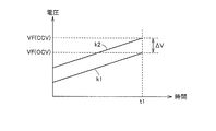
- FIG. 4 is a diagram showing the relationship between the OCV and CCV of the power storage device 150.
- line k ⁇ b> 1 indicates the OCV of power storage device 150
- line k ⁇ b> 2 indicates the CCV of power storage device 150.
- battery voltage VB detected by the battery sensor is CCV.
- CCV is higher than OCV by ⁇ V due to the influence of the internal resistance and polarization of power storage device 150.
- CCV battery voltage VB
- FIG. 5 is a diagram showing temporal changes in charging power, SOC, and battery voltage VB of power storage device 150 during external charging.
- the charging control of power storage device 150 is performed in two stages. That is, constant power charging (hereinafter also referred to as “CP (Constant Power) charging”) is performed so that the charging power Pch becomes a constant value Pc1 until time t1 immediately before the SOC reaches a predetermined full charging state SF. Then, after time t1, CP charging is performed so that the charging power Pch becomes a constant value Pc2 (
- CP Constant Power
- PLG-ECU 170 determines that charging connector 310 of charging cable 300 is connected to vehicle inlet 270 based on cable connection signal PISW, PLG-ECU 170 obtains voltage detection value VAC from voltage sensor 172. To do. Further, PLG-ECU 170 obtains a rated current that can be supplied to electric vehicle 10 via charging cable 300 based on the duty cycle of pilot signal CPLT. PLG-ECU 170 sets charging power Pch based on supply voltage VAC from external power supply 402 and the rated current of charging cable 300. For example, the constant value Pc1 is set to the maximum power that can be supplied from the charger 160 (the rated power of the charger 160).
- display unit 210 displays PLG-ECU 170 such as the charging time of power storage device 150 calculated by PLG-ECU 170 in timer charging control to be described later, and the scheduled charging start time set according to the charging time. It is a user interface for displaying the display information from.
- the display unit 210 includes a display lamp, an indicator such as an LED, or a liquid crystal display.
- the input unit 200 is a user interface for setting a charging end scheduled time (or a next vehicle operation starting scheduled time) in timer charging control described later.
- the scheduled charging end time set by input unit 200 is transmitted to PLG-ECU 170.
- the input unit 200 and the display unit 210 are described as individual elements, but these elements may be integrated into one element.
- a configuration in which the external power source 402 and the electric vehicle 10 are electromagnetically coupled in a non-contact manner to supply electric power specifically, a primary coil is provided on the external power source side.
- a secondary coil may be provided on the vehicle side, and power may be supplied from the external power source 402 to the electric vehicle 10 using the mutual inductance between the primary coil and the secondary coil. Even when such external charging is performed, the configuration after the charger 160 that converts the power supplied from the external power supply 402 can be made common.
- the electrically powered vehicle Since the electrically powered vehicle according to the present embodiment is a vehicle that can be externally charged, the electric power stored in power storage device 150 is stored by storing as much power as possible in power storage device 150 after the vehicle travels. The distance that the electric vehicle can travel can be increased using.
- PLG-ECU 170 determines that the SOC is in a predetermined fully charged state immediately before the scheduled charging end time based on the scheduled charging end time specified by the user. Charge control (timer charge control) of power storage device 150 is executed.
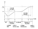
- FIG. 6 is a diagram for describing timer charging control executed by the PLG-ECU 170 in the present embodiment.
- FIG. 6 shows a temporal change in battery voltage VB of power storage device 150.
- the user when traveling of electrically powered vehicle 10 is completed at time t ⁇ b> 1, the user can externally charge electrically powered vehicle 10 by connecting charging connector 310 of charging cable 300 to vehicle inlet 270 (time t ⁇ b> 2). It becomes a state. If the user sets the scheduled charging end time (time t7) using the input unit 200 before the time t2 at which the external charging is possible, the PLG-ECU 170 causes the time t6 immediately before the scheduled charging end time (time t7). Timer charge control is executed so that the SOC reaches a predetermined full charge state SF.
- PLG-ECU 170 performs timer charging control of power storage device 150 in two stages.
- PLG-ECU 170 starts charging in the first stage.
- battery voltage VB increases.
- the PLG-ECU 170 ends the first stage charging.
- the PLG-ECU 170 starts the second stage charging.
- the PLG-ECU 170 sets VF (CCV) to the target voltage Vc2, and the battery voltage VB is set to the target voltage at time t6 immediately before the scheduled charging end time (time t7) designated by the user.
- the power storage device 150 is charged so as to reach Vc2.
- PLG-ECU 170 performs CP charging so that charging power Pch becomes constant value Pc1 until time t5 immediately before battery voltage VB reaches target voltage Vc2, and charging is performed after time t5.
- CP charging is executed so that the electric power Pch becomes a constant value Pc2.
- PLG-ECU 170 determines the charging time based on the required amount of charge of power storage device 150 when the scheduled charging end time (time t7) is designated by the user in order to execute the second-stage charging as described above. Determine the charging schedule. Specifically, PLG-ECU 170 calculates required charge amount ⁇ Q for charging SOC of power storage device 150 from SOC1 to SF based on target value SOC1 in the first-stage charging. This required charge amount ⁇ Q is calculated by the following equation (1), where Q is the full charge capacity of power storage device 150.
- the full charge capacity Q is corrected to reflect the deterioration state of the power storage device 150.
- the integrated value (actual value) of the charging power of power storage device 150 is calculated, and the theoretical value of charging power is calculated from the SOC calculated based on the relationship between OCV and SOC (FIG. 2).
- the full charge capacity Q can be corrected based on the deviation of the integrated value of the charging power with respect to the value.
- the PLG-ECU 170 calculates the charging time Tc2 required for the second stage charging based on the required charging amount ⁇ Q calculated by the above equation (1).
- This charging time Tc2 is calculated by the following equation (2), where ⁇ is the charging efficiency of power storage device 150.
- Tc2 ⁇ Q / Pch ⁇ ⁇ + ⁇ Tc (2)
- the second term indicates the correction term for the charging time.
- the variation in the charging time due to the temperature TB of the power storage device 150 takes into account that the charging characteristics of the power storage device 150 are affected by the temperature TB of the power storage device 150.
- the charging time may be longer than that at normal temperature.
- the PLG-ECU 170 calculates the charging time Tc2 required for the second stage charging by using the above equations (1) and (2).
- the required charge amount ⁇ Q shown in the equation (1) is a fixed value.
- the second stage charging time Tc2 shown in Expression (2) is also a fixed value. Therefore, when it is determined that electric vehicle 10 and external power supply 402 are coupled by charging cable 300 at time t2, PLG-ECU 170 takes into consideration the deterioration state of power storage device 150, temperature TB, and the like.
- the charging time Tc2 required for charging can be calculated. Then, the PLG-ECU 170 can determine the second scheduled charging start time (time t4) by subtracting the charging time Tc2 from the time t6 immediately before the scheduled charging end time (time t7).
- the scheduled charging start time is determined based on the scheduled charging end time and the required charge amount, and charging of the power storage device is started when the scheduled charging start time is reached. Therefore, immediately before the scheduled charging start time or immediately after the scheduled charging start time, the electric power necessary for traveling the vehicle is not stored in the power storage device, and the drivability of the vehicle may be reduced due to insufficient output of the power storage device. There is.
- the charging system according to the present embodiment as soon as electric vehicle 10 and external power supply 402 are coupled, the first stage of charging is performed to store a certain amount of power in power storage device 150. It is also possible to respond to a request to start traveling. As a result, the convenience of the vehicle is improved.
- the external power supply 402 fails during the chargeable time from the time when the external charging is possible (time t2) to the scheduled charging end time (time t7), and the power supply to the power storage device 150 is cut off. Even in such a case, the electric vehicle 10 can be driven using the electric power stored in the power storage device 150 by the first stage charging. Therefore, it is possible to reduce a risk that the power storage device 150 becomes insufficient in output due to a power failure of the external power supply 402.
- target value SOC1 in the first-stage charging is set to a value as high as possible on the condition that the deterioration of the power storage device 150 does not proceed, thereby preventing the power storage device 150 from deteriorating.
- Output power can be secured.
- target value SOC ⁇ b> 1 can be set such that electric power necessary for normal use of electric vehicle 10, for example, a round trip in a user's daily life area, is stored in power storage device 150.
- target value SOC ⁇ b> 1 may be set such that the power necessary for traveling from home to the nearest dealer is stored in power storage device 150. That is, target value SOC1 in the first stage charging can be determined in advance according to the predicted power consumption.
- the target value SOC1 may be set to an arbitrary value using the input unit 200 by the user.
- the second-stage charging is performed so that the SOC of power storage device 150 is in a predetermined fully charged state immediately before the scheduled charging end time, similarly to the conventional timer charging control.
- the time during which the SOC is maintained at a high value is shortened, so that the deterioration of the power storage device 150 can be suppressed. That is, the drivability and convenience of the vehicle can be improved while suppressing the deterioration of the power storage device 150.
- FIG. 7 is a diagram for describing a first modification of timer charging control executed by PLG-ECU 170.
- FIG. 7 shows a temporal change in battery voltage VB of power storage device 150.
- PLG-ECU 170 determines that the SOC of power storage device 150 exceeds target value SOC1 at the time (time t2) when electric vehicle 10 and external power supply 402 are coupled by charging cable 300. Then, the first stage of charging is not executed, and the power storage device 150 is placed in a charging standby state until the scheduled charging start time (time t4) is reached.
- This scheduled charging start time (time t4) is calculated from the necessary charge amount ⁇ Q (fixed value) for charging the SOC of power storage device 150 from SOC1 to SF using the above formulas (1) and (2). It is determined based on the charging time Tc2 (fixed value).
- charging time Tc2 By setting charging time Tc2 to a fixed value in this way, it is not necessary to calculate charging time Tc2 again based on the SOC of power storage device 150 at time t2. As a result, the control logic for performing the timer charging control of power storage device 150 can be simplified.
- the PLG-ECU 170 starts charging the power storage device 150 when the scheduled charging start time (time t4) is reached.
- time t4 the scheduled charging start time
- Vc2 target voltage
- Vc2 VF (CCV)
- the timer charging control in the charging system according to the embodiment of the present invention described above can be summarized in the following processing flow.
- FIG. 8 is a flowchart showing a control processing procedure for realizing timer charging control in the charging system according to the embodiment of the present invention.
- the flowchart shown in FIG. 8 can be realized by executing a program stored in advance by the PLG-ECU 170.
- PLG-ECU 170 acquires the scheduled charging end time set by the user in step S01 in order to execute timer charging control. Further, when PM-ECU 140 obtains battery data (VB, IB, TB) from monitoring unit 152 in step S02, in step S03, it calculates the current SOC of power storage device 150 based on the obtained battery data. PM-ECU 140 transmits the calculated SOC to PLG-ECU 170.
- battery data VB, IB, TB
- step S04 PLG-ECU 170 uses the above formula (1), and the required charge for charging SOC of power storage device 150 from target value SOC1 in the first stage charging to predetermined full charge state SF is performed.
- the amount ⁇ Q is calculated.
- the charging time Tc2 of the power storage device 150 by the second-stage charging is calculated.
- step S05 PLG-ECU 170 determines the second stage scheduled charging start time based on charging time Tc2 calculated in step S04 and the scheduled charging end time set by the user.
- PM-ECU 140 determines in step S06 whether battery voltage VB at the current time is equal to or higher than target voltage Vc1 corresponding to target value SOC1 in the first stage charging.
- PLG-ECU 170 proceeds to step S07 and performs the first stage charging.
- PLG-ECU 170 determines that the SOC of power storage device 150 has reached target value SOC1, and ends the first-stage charging.
- step S06 when the battery voltage VB is equal to or higher than the target voltage Vc1 (when YES is determined in step S06), the PLG-ECU 170 skips the process of step S07 and advances the process to step S08.
- Step S08 the PLG-ECU 170 determines whether or not the second stage charging start scheduled time calculated in Step S05 has been reached.
- PLG-ECU 170 determines whether or not the second stage charging start scheduled time calculated in Step S05 has been reached.
- PLG-ECU 170 continues to place power storage device 150 in a standby state.
- PLG-ECU 170 executes the second stage charging at step S09.
- battery voltage VB reaches target voltage Vc2
- PLG-ECU 170 determines that the SOC of power storage device 150 has reached SF, and ends the second stage charging.
- the second stage charging start time is determined by subtracting the second stage charging time Tc2 (fixed value) from the charging end scheduled time, and this charging start scheduled time is used.
- Tc2 fixed value
- the second stage charging is executed. This eliminates the need to adjust the charging time according to the remaining battery level before starting to charge the power storage device 150, thereby simplifying the control logic for timer charging control.
- FIG. 7 shows the second stage charging time Tc2 as a fixed value.
- the SOC may reach a predetermined full charge state SF at a time earlier than the scheduled charging end time. In this case, since the time during which the SOC is maintained in the fully charged state SF becomes long, the power storage device 150 may deteriorate.
- the remaining battery level of the power storage device 150 when the traveling of the electric vehicle 10 is completed is periodically learned, and the target value in the first stage charging is used using the learned value of the remaining battery level. Change SOC1.
- FIG. 9 is a diagram for explaining a second modification of the timer charging control executed by the PLG-ECU 170.
- FIG. 9 shows a temporal change in battery voltage VB of power storage device 150.
- PLG-ECU 170 acquires battery voltage VB of power storage device 150 each time traveling of electric vehicle 10 is completed, and stores it as a learning value for the remaining battery level.
- the PLG-ECU 170 compares the learning value of the remaining battery level (learning value of the battery voltage VB) with a predetermined target voltage Vc1 (initial value) in the first stage charging, and the learning value of the battery voltage VB is If it is determined that the voltage is higher than the target voltage Vc1 (initial value), the target voltage Vc1 is changed so as to match the learned value of the battery voltage VB. Then, the PLG-ECU 170 calculates the second stage charging time Tc2 based on the changed target voltage Vc1. As a result, the second-stage charging time Tc2 after the change is shorter than the charging time Tc2 based on the target voltage Vc1 (initial value).
- the second stage charging time Tc2 is changed in accordance with the learned value of the remaining battery level.
- the SOC is set to a predetermined fully charged state SF immediately before the scheduled charging end time.
- the power storage device 150 can be charged.
- the SOC of power storage device 150 can be prevented from being maintained in the fully charged state SF for a long time, deterioration of power storage device 150 due to high SOC can be suppressed.
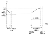
- FIG. 10 is a diagram for explaining a third modification of the timer charging control executed by the PLG-ECU 170.
- FIG. 10 shows a temporal change in battery voltage VB of power storage device 150.
- PLG-ECU 170 starts charging end scheduled time (time t7) from the current time (time t2). The chargeable time Tab until is calculated.
- PLG-ECU 170 calculates total charge time Tc until the SOC of power storage device 150 reaches a predetermined full charge state SF based on the remaining battery level of power storage device 150 at the current time. Specifically, PLG-ECU 170 calculates a required charge amount ⁇ Q for setting power storage device 150 to a predetermined full charge state SF based on the remaining battery level (SOC) at the current time. This required charge amount ⁇ Q is calculated by the following equation (3), where Q is the full charge capacity of power storage device 150 and SOC is the remaining battery level.
- ⁇ Q Q ⁇ (SF-SOC) / 100 (3)
- the PLG-ECU 170 calculates the total charge time Tc based on the required charge amount ⁇ Q calculated by the above equation (3).
- the total charging time Tc is calculated by the following formula (4), where ⁇ is the charging efficiency of the power storage device 150.
- Tc ⁇ Q / Pch ⁇ ⁇ + ⁇ Tc (4)
- the second term indicates the correction term for the charging time.
- the second term indicates the correction term for the charging time.
- And learning correction values
- the PLG-ECU 170 compares the chargeable time Tab with the total charge time Tc, and determines whether or not the timer charge control can be executed based on the comparison result. When the total charge time Tc exceeds the chargeable time Tab, the PLG-ECU 170 determines that the timer charge control cannot be performed, that is, the charge cannot be terminated at the scheduled charge end time.
- FIG. 11 is a flowchart showing a control processing procedure for realizing timer charging control in the charging system according to the third modification of the embodiment of the present invention.
- PM-ECU 140 calculates the current SOC of power storage device 150 through steps S01 to S03 similar to FIG.
- step S14 PLG-ECU 170 calculates a required charge amount ⁇ Q for charging power storage device 150 to a predetermined full charge state SF using equation (3) above. Then, the total charge time Tc of the power storage device 150 is calculated by substituting the calculated required charge amount ⁇ Q into the equation (4).
- step S15 the PLG-ECU 170 compares the total charge time Tc calculated in step S14 with the chargeable time Tab from the current time to the scheduled charge end time.
- PLG-ECU 170 executes timer charging control of power storage device 150 in step S16. This timer charging control is executed according to the processing flow shown in FIG.
- PLG-ECU 170 cancels the timer setting in step S17, and display 210 To notify the user. Further, PLG-ECU 170 performs normal charging control in step S18. Specifically, PLG-ECU 170 charges power storage device 150 with the rated power of charger 160 so that the SOC reaches a predetermined full charge state SF.
- PLG-ECU 170 determines whether or not charging of power storage device 150 can be ended at the scheduled charging end time when electric vehicle 10 and external power supply 402 are coupled. judge. If it is determined that charging cannot be terminated at the scheduled charging end time, the PLG-ECU 170 notifies the user to that effect, and does not execute the timer charging control. The power storage device 150 is charged with the rated power. This allows the user to recognize that the power storage device 150 has not reached the predetermined fully charged state at the scheduled charging end time (next vehicle operation start time), and as much as possible by the scheduled charging end time. Can be stored in the power storage device 150. As a result, the drivability and convenience of the electric vehicle 10 can be improved.
- the first-stage charging corresponds to the “first charging operation” in the present invention
- the second-stage charging is the “second charging” in the present invention.
- the PLG-ECU 170 implements a “control device” according to the present invention.
- the electric vehicle is exemplified as a representative example of the vehicle to which the charging system according to the present invention is applied.
- the present invention includes a power storage device configured to be chargeable by a power source outside the vehicle. It is possible to apply to the vehicle which did.
- the present invention can be applied to a vehicle charging system having a timer charging function.
Abstract
Description
本実施の形態に従う電動車両は、外部充電が可能な車両であるため、車両の走行完了後は、蓄電装置150に可能な限り多くの電力を蓄えておくことによって、蓄電装置150に蓄えた電力を用いて電動車両が走行可能な距離を拡大することができる。 (Timer charging control)
Since the electrically powered vehicle according to the present embodiment is a vehicle that can be externally charged, the electric power stored in
ここで、蓄電装置150の劣化が進行すると、満充電容量Qが低下することから、上記式(1)において、満充電容量Qを蓄電装置150の劣化状態を反映させるように補正する。たとえば、蓄電装置150の充電電力の積算値(実績値)を演算するとともに、OCVおよびSOCの関係(図2)に基づいて算出されるSOCから充電電力の理論値を演算し、充電電力の理論値に対する充電電力の積算値の偏差に基づいて満充電容量Qを補正することができる。 ΔQ = Q × (SF-SOC1) / 100 (1)
Here, as the deterioration of the
なお、上記式(2)において、右辺の第1項は充電電力Pch=Pc1で蓄電装置150を充電した場合の充電時間を示し、第2項は充電時間の補正項を示す。この補正項ΔTcは、蓄電装置150の温度TBによる充電時間の変動分、充電電力Pch=Pc2で蓄電装置150を充電するのに必要な充電時間、および学習補正値などを含む。このうち、蓄電装置150の温度TBによる充電時間の変動分とは、蓄電装置150の充電特性が蓄電装置150の温度TBによって影響を受けることを考慮したものである。たとえば、蓄電装置150の低温時には蓄電装置150の受入れ可能な電力が低下するため、常温時と比較して充電時間が長くなる虞がある。また、充電電力Pch=Pc2で蓄電装置150を充電するのに必要な充電時間とは、図6に示す時刻t5から時刻t6までの時間に相当する。この充電時間についても蓄電装置150の温度TBに応じて補正することができる。 Tc2 = ΔQ / Pch × α + ΔTc (2)
In the above formula (2), the first term on the right side indicates the charging time when the
上述したようにタイマー充電制御を2段階に分けて行なう構成においては、電動車両10と外部電源402とが充電ケーブル300によって結合された時刻(図7の時刻t2)における蓄電装置150のSOCが第1段階の充電での目標値SOC1を上回っている場合が起こり得る。図7は、PLG-ECU170で実行されるタイマー充電制御の第1の変形例を説明するための図である。図7は、蓄電装置150の電池電圧VBの時間的な変化を示す。 [Modification 1]
In the configuration in which timer charging control is performed in two stages as described above, the SOC of
ここで、上記の実施の形態においては、充電終了予定時刻から第2段階の充電時間Tc2(固定値)を差し引くことにより第2段階の充電開始予定時刻が決定され、この充電開始予定時刻を用いて第2段階の充電が実行される。これにより、蓄電装置150の充電を開始する前の電池残量に応じて充電時間を調整する処理が不要となるため、タイマー充電制御のための制御ロジックを簡素化できる。 [Modification 2]
Here, in the above-described embodiment, the second stage charging start time is determined by subtracting the second stage charging time Tc2 (fixed value) from the charging end scheduled time, and this charging start scheduled time is used. Thus, the second stage charging is executed. This eliminates the need to adjust the charging time according to the remaining battery level before starting to charge the
図10は、PLG-ECU170で実行されるタイマー充電制御の第3の変形例を説明するための図である。図10は、蓄電装置150の電池電圧VBの時間的な変化を示す。 [Modification 3]
FIG. 10 is a diagram for explaining a third modification of the timer charging control executed by the PLG-
なお、上記式(1)で説明したのと同様に、式(3)においても、満充電容量Qを蓄電装置150の劣化状態を反映させるように補正することができる。そして、PLG-ECU170は、上記式(3)により演算した必要充電量ΔQに基づいて、トータル充電時間Tcを演算する。このトータル充電時間Tcは、蓄電装置150の充電効率をαとすると、以下の式(4)で算出される。 ΔQ = Q × (SF-SOC) / 100 (3)
Note that, as described in the above equation (1), in the equation (3), the full charge capacity Q can be corrected to reflect the deterioration state of the
なお、上記式(4)において、右辺の第1項は充電電力Pch=Pc1で蓄電装置150を充電した場合の充電時間を示し、第2項は充電時間の補正項を示す。この補正項ΔTcは、上記式(2)で説明したのと同様に、蓄電装置150の温度TBによる充電時間の変動分、充電電力Pch=Pc2で蓄電装置150を充電するのに必要な充電時間、および学習補正値などを含む。 Tc = ΔQ / Pch × α + ΔTc (4)
In the above formula (4), the first term on the right side indicates the charging time when the
Claims (7)
- 車両(10)に搭載される蓄電装置(150)の充電を制御するための車両の充電システムであって、
外部電源(402)からの電力を前記蓄電装置(150)の充電電力に変換可能に構成された充電器(160)と、
前記蓄電装置(150)の充電終了予定時刻を指定するための入力部(200)と、
前記蓄電装置(150)の充電状態が所定の満充電状態となるように、前記充電器(160)を制御するための制御装置(170)とを備え、
前記制御装置(170)は、前記外部電源(402)と前記車両(10)とが結合されたときには、前記所定の満充電状態よりも低い充電状態を目標値として、前記充電状態が前記目標値に到達するまで前記充電器(160)を制御する第1の充電動作を実行する一方で、前記充電状態が前記目標値に到達した後は、前記蓄電装置(150)の充電を停止させるとともに、前記充電終了予定時刻に前記充電状態が前記所定の満充電状態となるように前記充電器(160)を制御する第2の充電動作を実行するために前記蓄電装置(150)の充電を再開する、車両の充電システム。 A vehicle charging system for controlling charging of a power storage device (150) mounted on a vehicle (10),
A charger (160) configured to convert electric power from an external power source (402) into charging power of the power storage device (150);
An input unit (200) for designating a scheduled charging end time of the power storage device (150);
A controller (170) for controlling the charger (160) so that the state of charge of the power storage device (150) becomes a predetermined full charge state,
When the external power source (402) and the vehicle (10) are coupled, the control device (170) sets the charge state lower than the predetermined full charge state as a target value, and the charge state is the target value. While the first charging operation for controlling the charger (160) is performed until reaching the target value, the charging of the power storage device (150) is stopped after the charging state has reached the target value, The charging of the power storage device (150) is resumed in order to execute a second charging operation for controlling the charger (160) so that the charging state becomes the predetermined full charging state at the scheduled charging end time. , Vehicle charging system. - 前記制御装置(170)は、前記充電終了予定時刻と、前記充電状態を前記目標値から前記所定の満充電状態まで上昇させるのに必要な充電時間とに基づいて、前記第2の充電動作の開始予定時刻を設定するとともに、前記第2の充電動作の開始予定時刻に到達したときに前記蓄電装置(150)の充電を再開する、請求項1に記載の車両の充電システム。 The control device (170) performs the second charging operation based on the scheduled charging end time and a charging time required to raise the charging state from the target value to the predetermined full charging state. The vehicle charging system according to claim 1, wherein a scheduled start time is set and charging of the power storage device (150) is resumed when the scheduled start time of the second charging operation is reached.
- 前記制御装置(170)は、前記外部電源(402)と前記車両(10)とが結合されたときに、前記充電状態が前記目標値よりも高い場合には、前記第1の充電動作を不実行とするとともに、前記第2の充電動作を実行する、請求項1または2に記載の車両の充電システム。 The controller (170) disables the first charging operation if the state of charge is higher than the target value when the external power source (402) and the vehicle (10) are coupled. The vehicle charging system according to claim 1, wherein the second charging operation is executed as well as being executed.
- 前記制御装置(170)は、前記外部電源(402)と前記車両(10)とが結合されたときに、前記充電状態を前記所定の満充電状態にするのに必要なトータル充電時間が、現在の時刻から前記充電終了予定時刻までの充電可能時間を超える場合には、前記第1および第2の充電動作を不実行とする一方で、前記充電状態が前記所定の満充電状態となるように前記充電器(160)を制御する、請求項1に記載の車両の充電システム。 When the external power source (402) and the vehicle (10) are coupled together, the control device (170) is configured so that a total charging time required to set the charging state to the predetermined full charging state is When the chargeable time from the time until the scheduled charging end time is exceeded, the first and second charging operations are not executed, while the charged state becomes the predetermined full charged state. The vehicle charging system according to claim 1, wherein the charger is controlled.
- 前記制御装置(170)は、前記車両(10)の走行が完了したときの前記充電状態の学習値に応じて、前記目標値を変更する、請求項1に記載の車両の充電システム。 The vehicle charging system according to claim 1, wherein the control device (170) changes the target value in accordance with a learning value of the state of charge when the vehicle (10) has traveled.
- 前記制御装置(170)は、前記充電状態の学習値が高くなるに従って、前記目標値を増加させる、請求項5に記載の車両の充電システム。 The vehicle charging system according to claim 5, wherein the control device (170) increases the target value as the learning value of the charging state increases.
- 車両(10)に搭載される蓄電装置(150)の充電を制御するための車両の充電方法であって、
前記車両(10)は、
外部電源(402)からの電力を前記蓄電装置(150)の充電電力に変換可能に構成された充電器(160)と、
前記蓄電装置(150)の充電終了予定時刻を指定するための入力部(200)とを含み、
前記車両の充電方法は、
前記外部電源(402)と前記車両(10)とが結合されたときには、所定の満充電状態よりも低い充電状態を目標値として、前記充電状態が前記目標値に到達するまで前記充電器(160)を制御する第1の充電動作を実行するステップと、
前記充電状態が前記目標値に到達した後は、前記蓄電装置(150)の充電を停止するとともに、前記充電終了予定時刻に前記充電状態が前記所定の満充電状態となるように前記充電器(160)を制御する第2の充電動作を実行するために前記蓄電装置(150)の充電を再開するステップとを備える、車両の充電方法。 A vehicle charging method for controlling charging of a power storage device (150) mounted on a vehicle (10), comprising:
The vehicle (10)
A charger (160) configured to convert electric power from an external power source (402) into charging power of the power storage device (150);
An input unit (200) for designating a scheduled charging end time of the power storage device (150),
The vehicle charging method is:
When the external power source (402) and the vehicle (10) are coupled, the charger (160) until the state of charge reaches the target value, with a state of charge lower than a predetermined fully charged state as a target value. Performing a first charging operation for controlling
After the state of charge reaches the target value, the charging of the power storage device (150) is stopped, and the charger (150) is set so that the state of charge becomes the predetermined full charge state at the scheduled charging end time. 160) resuming charging of the power storage device (150) in order to execute a second charging operation for controlling 160).
Priority Applications (8)
| Application Number | Priority Date | Filing Date | Title |
|---|---|---|---|
| IN3025DEN2014 IN2014DN03025A (en) | 2011-10-07 | 2011-10-07 | |
| US14/349,580 US9618954B2 (en) | 2011-10-07 | 2011-10-07 | Vehicle charging system and vehicle charging method with first and second charging operations |
| PCT/JP2011/073205 WO2013051151A1 (en) | 2011-10-07 | 2011-10-07 | Vehicle charging system and method for charging vehicle |
| RU2014117499/11A RU2561162C1 (en) | 2011-10-07 | 2011-10-07 | Vehicle charging system and method of vehicle charging |
| JP2013537368A JP5710775B2 (en) | 2011-10-07 | 2011-10-07 | Vehicle charging system and vehicle charging method |
| EP11873695.8A EP2765669A4 (en) | 2011-10-07 | 2011-10-07 | Vehicle charging system and method for charging vehicle |
| BR112014008318-5A BR112014008318B1 (en) | 2011-10-07 | 2011-10-07 | VEHICLE CHARGING SYSTEM AND VEHICLE CHARGING METHOD |
| CN201180073946.5A CN103875148B (en) | 2011-10-07 | 2011-10-07 | The charging system of vehicle and the charging method of vehicle |
Applications Claiming Priority (1)
| Application Number | Priority Date | Filing Date | Title |
|---|---|---|---|
| PCT/JP2011/073205 WO2013051151A1 (en) | 2011-10-07 | 2011-10-07 | Vehicle charging system and method for charging vehicle |
Publications (1)
| Publication Number | Publication Date |
|---|---|
| WO2013051151A1 true WO2013051151A1 (en) | 2013-04-11 |
Family
ID=48043341
Family Applications (1)
| Application Number | Title | Priority Date | Filing Date |
|---|---|---|---|
| PCT/JP2011/073205 WO2013051151A1 (en) | 2011-10-07 | 2011-10-07 | Vehicle charging system and method for charging vehicle |
Country Status (8)
| Country | Link |
|---|---|
| US (1) | US9618954B2 (en) |
| EP (1) | EP2765669A4 (en) |
| JP (1) | JP5710775B2 (en) |
| CN (1) | CN103875148B (en) |
| BR (1) | BR112014008318B1 (en) |
| IN (1) | IN2014DN03025A (en) |
| RU (1) | RU2561162C1 (en) |
| WO (1) | WO2013051151A1 (en) |
Cited By (11)
| Publication number | Priority date | Publication date | Assignee | Title |
|---|---|---|---|---|
| JP2014241656A (en) * | 2013-06-11 | 2014-12-25 | 株式会社豊田自動織機 | Charging start control method of secondary battery, and charging device |
| JP2015012654A (en) * | 2013-06-27 | 2015-01-19 | トヨタホーム株式会社 | Charge control system |
| CN105098874A (en) * | 2014-05-15 | 2015-11-25 | 福特全球技术公司 | Method for management of electrical current supply in motor vehicle |
| JP2016073057A (en) * | 2014-09-29 | 2016-05-09 | トヨタ自動車株式会社 | Electric vehicle |
| JP2018113744A (en) * | 2017-01-10 | 2018-07-19 | トヨタ自動車株式会社 | Charge control device and charge control method |
| WO2018215864A1 (en) * | 2017-05-22 | 2018-11-29 | 株式会社半導体エネルギー研究所 | Charging control system and charging control device |
| JP2021521764A (en) * | 2018-04-13 | 2021-08-26 | ローベルト ボツシユ ゲゼルシヤフト ミツト ベシユレンクテル ハフツングRobert Bosch Gmbh | Optimization system and optimization method |
| JP2021132476A (en) * | 2020-02-20 | 2021-09-09 | 株式会社デンソー | Charge control device |
| JP2022536448A (en) * | 2019-05-20 | 2022-08-17 | ボルボトラックコーポレーション | Method, computer program, computer readable medium, control unit and battery charging system for controlling charging of an electric vehicle |
| US11480621B2 (en) | 2017-11-02 | 2022-10-25 | Semiconductor Energy Laboratory Co., Ltd. | Capacity estimation method and capacity estimation system for power storage device |
| JP7435332B2 (en) | 2020-02-06 | 2024-02-21 | 株式会社デンソー | vehicle charging system |
Families Citing this family (29)
| Publication number | Priority date | Publication date | Assignee | Title |
|---|---|---|---|---|
| JP5803965B2 (en) * | 2013-03-25 | 2015-11-04 | トヨタ自動車株式会社 | vehicle |
| GB2536242A (en) * | 2015-03-09 | 2016-09-14 | Intelligent Energy Ltd | A charge controller |
| JP6183411B2 (en) * | 2015-05-26 | 2017-08-23 | トヨタ自動車株式会社 | vehicle |
| JP6223406B2 (en) * | 2015-11-28 | 2017-11-01 | 本田技研工業株式会社 | Power supply system |
| DE102015016983A1 (en) | 2015-12-24 | 2016-08-18 | Daimler Ag | A power train assembly |
| WO2018037261A1 (en) | 2016-08-23 | 2018-03-01 | Pismo Labs Technology Ltd. | Methods and systems for distributing electricity to multiple loads based on a scheduler and ammeter measurements |
| US10471846B2 (en) * | 2016-08-23 | 2019-11-12 | Pismo Labs Technology Limited | Methods and systems for supplying electricity to multiple loads with current measurements |
| JP6493371B2 (en) * | 2016-12-06 | 2019-04-03 | トヨタ自動車株式会社 | Vehicle and charging method thereof |
| JP6583294B2 (en) * | 2017-01-17 | 2019-10-02 | トヨタ自動車株式会社 | Electric vehicle |
| US10220718B2 (en) | 2017-04-07 | 2019-03-05 | Honda Motor Co., Ltd. | System and method for creating a charging schedule for an electric vehicle |
| US10625625B2 (en) | 2017-04-07 | 2020-04-21 | Honda Motor Co., Ltd. | System and method for creating a charging schedule for an electric vehicle |
| EP3425762A1 (en) * | 2017-07-03 | 2019-01-09 | Ningbo Geely Automobile Research & Development Co. Ltd. | Method and electronic device for managing charging |
| JP6841179B2 (en) * | 2017-07-14 | 2021-03-10 | 住友電気工業株式会社 | Power storage device and power supply system |
| US11658503B2 (en) * | 2017-07-31 | 2023-05-23 | Nissan Motor Co., Ltd. | Charging time computation method and charge control device |
| DK3453559T3 (en) * | 2017-09-12 | 2020-07-13 | Dietmar Niederl | Charging cable and adapter for electrically charging an energy storage device on an energy supply device |
| KR102515606B1 (en) * | 2017-10-31 | 2023-03-28 | 삼성에스디아이 주식회사 | Method, battery pack, and electronic device for displaying battery charge capacity |
| US10882411B2 (en) * | 2018-01-18 | 2021-01-05 | Ford Global Technologies, Llc | Smart charging schedules for battery systems and associated methods for electrified vehicles |
| KR102586914B1 (en) * | 2018-05-23 | 2023-10-10 | 현대자동차주식회사 | Power converting apparatus for charging vehicle battery and Method for controlling the same |
| JP7099275B2 (en) * | 2018-11-21 | 2022-07-12 | トヨタ自動車株式会社 | In-vehicle control device |
| CN111347912B (en) * | 2018-12-20 | 2023-09-05 | 勃姆巴迪尔运输有限公司 | System and method for adjusting a charge rate of a vehicle battery based on an expected passenger load |
| JP7172690B2 (en) * | 2019-02-12 | 2022-11-16 | トヨタ自動車株式会社 | BATTERY SYSTEM AND SECONDARY BATTERY SOC ESTIMATION METHOD |
| KR20220012236A (en) | 2019-05-24 | 2022-02-03 | 가부시키가이샤 한도오따이 에네루기 켄큐쇼 | Estimation method of internal resistance of secondary battery and abnormality detection system of secondary battery |
| DE102019208071A1 (en) * | 2019-06-04 | 2020-12-10 | Robert Bosch Gmbh | Method and device for carrying out a charging strategy for energy storage |
| JP7230767B2 (en) * | 2019-10-09 | 2023-03-01 | トヨタ自動車株式会社 | Charging control device, vehicle, charging system and charging control method |
| CN113126732B (en) * | 2020-01-15 | 2024-03-08 | 戴尔产品有限公司 | Charging system for power standby equipment |
| US20210281092A1 (en) * | 2020-03-09 | 2021-09-09 | Medtronic Minimed, Inc. | Networked dynamic management of charge |
| JP2021181141A (en) * | 2020-05-20 | 2021-11-25 | セイコーエプソン株式会社 | Charging method and charging system |
| US11462066B2 (en) * | 2020-10-20 | 2022-10-04 | Honda Motor Co., Ltd. | System and method for locking a charging port to charge an electric vehicle |
| JP7450523B2 (en) * | 2020-12-08 | 2024-03-15 | プライムプラネットエナジー&ソリューションズ株式会社 | Vehicle driving system and vehicle |
Citations (3)
| Publication number | Priority date | Publication date | Assignee | Title |
|---|---|---|---|---|
| JP3554057B2 (en) | 1995-02-06 | 2004-08-11 | 本田技研工業株式会社 | Battery charging control device for electric vehicles |
| WO2010084598A1 (en) * | 2009-01-23 | 2010-07-29 | トヨタ自動車株式会社 | Charge control device |
| JP2011151891A (en) * | 2010-01-19 | 2011-08-04 | Sony Corp | Method and apparatus for charging secondary battery |
Family Cites Families (10)
| Publication number | Priority date | Publication date | Assignee | Title |
|---|---|---|---|---|
| JP2001292533A (en) * | 2000-04-04 | 2001-10-19 | Japan Storage Battery Co Ltd | Battery management device for electric vehicle |
| JP2002142378A (en) * | 2000-10-31 | 2002-05-17 | Canon Inc | Apparatus and method for charging and storage medium |
| JP5168891B2 (en) * | 2006-11-28 | 2013-03-27 | 日産自動車株式会社 | Electric vehicle charging power management system |
| JP5223232B2 (en) * | 2007-04-26 | 2013-06-26 | 株式会社エクォス・リサーチ | Electric vehicle charge control system and electric vehicle charge control method |
| US7782021B2 (en) | 2007-07-18 | 2010-08-24 | Tesla Motors, Inc. | Battery charging based on cost and life |
| JP2009106027A (en) | 2007-10-22 | 2009-05-14 | Toyota Motor Corp | Battery controller and control method, program to achieve the method in computer, and recording medium recording the program |
| JP4715881B2 (en) | 2008-07-25 | 2011-07-06 | トヨタ自動車株式会社 | Power supply system and vehicle equipped with the same |
| KR101047413B1 (en) * | 2009-11-17 | 2011-07-08 | 기아자동차주식회사 | Indoor air conditioning system and method using battery charging control of electric vehicle |
| EP2502774B1 (en) * | 2009-11-17 | 2015-02-25 | Toyota Jidosha Kabushiki Kaisha | Vehicle and method for controlling vehicle |
| JP5051794B2 (en) * | 2009-12-17 | 2012-10-17 | トヨタ自動車株式会社 | Charger |
-
2011
- 2011-10-07 EP EP11873695.8A patent/EP2765669A4/en not_active Withdrawn
- 2011-10-07 JP JP2013537368A patent/JP5710775B2/en active Active
- 2011-10-07 IN IN3025DEN2014 patent/IN2014DN03025A/en unknown
- 2011-10-07 BR BR112014008318-5A patent/BR112014008318B1/en active IP Right Grant
- 2011-10-07 RU RU2014117499/11A patent/RU2561162C1/en active
- 2011-10-07 WO PCT/JP2011/073205 patent/WO2013051151A1/en active Application Filing
- 2011-10-07 US US14/349,580 patent/US9618954B2/en active Active
- 2011-10-07 CN CN201180073946.5A patent/CN103875148B/en active Active
Patent Citations (3)
| Publication number | Priority date | Publication date | Assignee | Title |
|---|---|---|---|---|
| JP3554057B2 (en) | 1995-02-06 | 2004-08-11 | 本田技研工業株式会社 | Battery charging control device for electric vehicles |
| WO2010084598A1 (en) * | 2009-01-23 | 2010-07-29 | トヨタ自動車株式会社 | Charge control device |
| JP2011151891A (en) * | 2010-01-19 | 2011-08-04 | Sony Corp | Method and apparatus for charging secondary battery |
Non-Patent Citations (1)
| Title |
|---|
| See also references of EP2765669A4 |
Cited By (17)
| Publication number | Priority date | Publication date | Assignee | Title |
|---|---|---|---|---|
| JP2014241656A (en) * | 2013-06-11 | 2014-12-25 | 株式会社豊田自動織機 | Charging start control method of secondary battery, and charging device |
| JP2015012654A (en) * | 2013-06-27 | 2015-01-19 | トヨタホーム株式会社 | Charge control system |
| CN105098874A (en) * | 2014-05-15 | 2015-11-25 | 福特全球技术公司 | Method for management of electrical current supply in motor vehicle |
| CN105098874B (en) * | 2014-05-15 | 2019-12-03 | 福特全球技术公司 | Method for the management that electric current in motor vehicles is supplied |
| JP2016073057A (en) * | 2014-09-29 | 2016-05-09 | トヨタ自動車株式会社 | Electric vehicle |
| JP2018113744A (en) * | 2017-01-10 | 2018-07-19 | トヨタ自動車株式会社 | Charge control device and charge control method |
| WO2018215864A1 (en) * | 2017-05-22 | 2018-11-29 | 株式会社半導体エネルギー研究所 | Charging control system and charging control device |
| JPWO2018215864A1 (en) * | 2017-05-22 | 2020-04-09 | 株式会社半導体エネルギー研究所 | Charge control system and charge control device |
| US11480621B2 (en) | 2017-11-02 | 2022-10-25 | Semiconductor Energy Laboratory Co., Ltd. | Capacity estimation method and capacity estimation system for power storage device |
| JP2021521764A (en) * | 2018-04-13 | 2021-08-26 | ローベルト ボツシユ ゲゼルシヤフト ミツト ベシユレンクテル ハフツングRobert Bosch Gmbh | Optimization system and optimization method |
| US11685284B2 (en) | 2018-04-13 | 2023-06-27 | Robert Bosch Gmbh | Optimization system and an optimization method |
| JP7401455B2 (en) | 2018-04-13 | 2023-12-19 | ローベルト ボツシユ ゲゼルシヤフト ミツト ベシユレンクテル ハフツング | Optimization system and optimization method |
| JP2022536448A (en) * | 2019-05-20 | 2022-08-17 | ボルボトラックコーポレーション | Method, computer program, computer readable medium, control unit and battery charging system for controlling charging of an electric vehicle |
| JP7288082B2 (en) | 2019-05-20 | 2023-06-06 | ボルボトラックコーポレーション | Method, computer program, computer readable medium, control unit and battery charging system for controlling charging of an electric vehicle |
| JP7435332B2 (en) | 2020-02-06 | 2024-02-21 | 株式会社デンソー | vehicle charging system |
| JP2021132476A (en) * | 2020-02-20 | 2021-09-09 | 株式会社デンソー | Charge control device |
| JP7247920B2 (en) | 2020-02-20 | 2023-03-29 | 株式会社デンソー | charging controller |
Also Published As
| Publication number | Publication date |
|---|---|
| EP2765669A4 (en) | 2015-10-07 |
| IN2014DN03025A (en) | 2015-05-08 |
| BR112014008318A2 (en) | 2017-04-18 |
| RU2561162C1 (en) | 2015-08-27 |
| BR112014008318A8 (en) | 2017-10-10 |
| JP5710775B2 (en) | 2015-04-30 |
| US20140236379A1 (en) | 2014-08-21 |
| CN103875148B (en) | 2017-07-11 |
| US9618954B2 (en) | 2017-04-11 |
| BR112014008318B1 (en) | 2020-03-31 |
| EP2765669A1 (en) | 2014-08-13 |
| CN103875148A (en) | 2014-06-18 |
| JPWO2013051151A1 (en) | 2015-03-30 |
Similar Documents
| Publication | Publication Date | Title |
|---|---|---|
| JP5710775B2 (en) | Vehicle charging system and vehicle charging method | |
| JP2013081324A (en) | Vehicle charging system and vehicle charging method | |
| US9216655B2 (en) | Vehicle and power supply system | |
| US8368347B2 (en) | Vehicular charging system | |
| EP2535218B1 (en) | Power supply system for electric vehicle, and control method thereof | |
| EP2783899B1 (en) | Charging system and charging reservation method | |
| EP2830185B1 (en) | Electric vehicle, electric power facilities and electric power supply system | |
| JP5585564B2 (en) | VEHICLE CONTROL DEVICE, CONTROL METHOD, AND VEHICLE | |
| JP5454697B2 (en) | VEHICLE POWER SUPPLY DEVICE, VEHICLE EQUIPPED WITH THE SAME AND CONTROL METHOD FOR CAR | |
| EP2823987B1 (en) | Electric-powered vehicle and method for controlling same | |
| EP2774797B1 (en) | Power source system and vehicle provided therewith, and method of controlling power source system | |
| US9701186B2 (en) | Vehicle | |
| JP5710440B2 (en) | Vehicle charging system and vehicle charging method | |
| WO2013001620A1 (en) | Power supply system for vehicle | |
| JP5831304B2 (en) | Vehicle and vehicle control method | |
| JP2012085403A (en) | Controller and control method of vehicle | |
| WO2010070761A1 (en) | Hybrid vehicle | |
| JP2022148243A (en) | vehicle |
Legal Events
| Date | Code | Title | Description |
|---|---|---|---|
| DPE2 | Request for preliminary examination filed before expiration of 19th month from priority date (pct application filed from 20040101) | ||
| 121 | Ep: the epo has been informed by wipo that ep was designated in this application |
Ref document number: 11873695 Country of ref document: EP Kind code of ref document: A1 |
|
| ENP | Entry into the national phase |
Ref document number: 2013537368 Country of ref document: JP Kind code of ref document: A |
|
| WWE | Wipo information: entry into national phase |
Ref document number: 14349580 Country of ref document: US |
|
| NENP | Non-entry into the national phase |
Ref country code: DE |
|
| REEP | Request for entry into the european phase |
Ref document number: 2011873695 Country of ref document: EP |
|
| WWE | Wipo information: entry into national phase |
Ref document number: 2011873695 Country of ref document: EP |
|
| ENP | Entry into the national phase |
Ref document number: 2014117499 Country of ref document: RU Kind code of ref document: A |
|
| REG | Reference to national code |
Ref country code: BR Ref legal event code: B01A Ref document number: 112014008318 Country of ref document: BR |
|
| ENP | Entry into the national phase |
Ref document number: 112014008318 Country of ref document: BR Kind code of ref document: A2 Effective date: 20140407 |