JP6096513B2 - Plasma pump and membrane oxygen separation method and system - Google Patents
Plasma pump and membrane oxygen separation method and system Download PDFInfo
- Publication number
- JP6096513B2 JP6096513B2 JP2012543966A JP2012543966A JP6096513B2 JP 6096513 B2 JP6096513 B2 JP 6096513B2 JP 2012543966 A JP2012543966 A JP 2012543966A JP 2012543966 A JP2012543966 A JP 2012543966A JP 6096513 B2 JP6096513 B2 JP 6096513B2
- Authority
- JP
- Japan
- Prior art keywords
- oxygen
- containing gas
- membrane
- gas
- inorganic film
- Prior art date
- Legal status (The legal status is an assumption and is not a legal conclusion. Google has not performed a legal analysis and makes no representation as to the accuracy of the status listed.)
- Active
Links
- QVGXLLKOCUKJST-UHFFFAOYSA-N atomic oxygen Chemical compound [O] QVGXLLKOCUKJST-UHFFFAOYSA-N 0.000 title claims description 138
- 239000001301 oxygen Substances 0.000 title claims description 138
- 229910052760 oxygen Inorganic materials 0.000 title claims description 138
- 239000012528 membrane Substances 0.000 title claims description 70
- 238000000926 separation method Methods 0.000 title claims description 13
- 239000007789 gas Substances 0.000 claims description 108
- 238000000034 method Methods 0.000 claims description 18
- MYMOFIZGZYHOMD-UHFFFAOYSA-N Dioxygen Chemical compound O=O MYMOFIZGZYHOMD-UHFFFAOYSA-N 0.000 claims description 11
- 238000001816 cooling Methods 0.000 claims description 10
- 238000010438 heat treatment Methods 0.000 claims description 8
- 238000003860 storage Methods 0.000 claims description 8
- 239000012212 insulator Substances 0.000 claims description 6
- 230000006835 compression Effects 0.000 claims description 5
- 238000007906 compression Methods 0.000 claims description 5
- 238000009413 insulation Methods 0.000 claims description 5
- 230000008878 coupling Effects 0.000 description 11
- 238000010168 coupling process Methods 0.000 description 11
- 238000005859 coupling reaction Methods 0.000 description 11
- IJGRMHOSHXDMSA-UHFFFAOYSA-N Atomic nitrogen Chemical compound N#N IJGRMHOSHXDMSA-UHFFFAOYSA-N 0.000 description 9
- 230000001965 increasing effect Effects 0.000 description 8
- 238000002640 oxygen therapy Methods 0.000 description 7
- 239000003570 air Substances 0.000 description 5
- 230000008901 benefit Effects 0.000 description 5
- 229910052757 nitrogen Inorganic materials 0.000 description 5
- 230000007423 decrease Effects 0.000 description 4
- 238000004519 manufacturing process Methods 0.000 description 4
- 239000000463 material Substances 0.000 description 4
- 230000008569 process Effects 0.000 description 4
- 238000011282 treatment Methods 0.000 description 4
- 230000000694 effects Effects 0.000 description 3
- 238000012423 maintenance Methods 0.000 description 3
- 239000012466 permeate Substances 0.000 description 3
- 238000004659 sterilization and disinfection Methods 0.000 description 3
- 238000011144 upstream manufacturing Methods 0.000 description 3
- 206010021143 Hypoxia Diseases 0.000 description 2
- VYPSYNLAJGMNEJ-UHFFFAOYSA-N Silicium dioxide Chemical compound O=[Si]=O VYPSYNLAJGMNEJ-UHFFFAOYSA-N 0.000 description 2
- 239000000919 ceramic Substances 0.000 description 2
- 239000013078 crystal Substances 0.000 description 2
- 239000012530 fluid Substances 0.000 description 2
- TWNQGVIAIRXVLR-UHFFFAOYSA-N oxo(oxoalumanyloxy)alumane Chemical compound O=[Al]O[Al]=O TWNQGVIAIRXVLR-UHFFFAOYSA-N 0.000 description 2
- 230000035699 permeability Effects 0.000 description 2
- 230000008439 repair process Effects 0.000 description 2
- 230000001954 sterilising effect Effects 0.000 description 2
- 230000001225 therapeutic effect Effects 0.000 description 2
- OKTJSMMVPCPJKN-UHFFFAOYSA-N Carbon Chemical compound [C] OKTJSMMVPCPJKN-UHFFFAOYSA-N 0.000 description 1
- 208000006545 Chronic Obstructive Pulmonary Disease Diseases 0.000 description 1
- 230000001154 acute effect Effects 0.000 description 1
- XAGFODPZIPBFFR-UHFFFAOYSA-N aluminium Chemical compound [Al] XAGFODPZIPBFFR-UHFFFAOYSA-N 0.000 description 1
- 229910052782 aluminium Inorganic materials 0.000 description 1
- 239000012080 ambient air Substances 0.000 description 1
- 239000008280 blood Substances 0.000 description 1
- 210000004369 blood Anatomy 0.000 description 1
- WUKWITHWXAAZEY-UHFFFAOYSA-L calcium difluoride Chemical compound [F-].[F-].[Ca+2] WUKWITHWXAAZEY-UHFFFAOYSA-L 0.000 description 1
- 229910052799 carbon Inorganic materials 0.000 description 1
- 230000015556 catabolic process Effects 0.000 description 1
- 230000019522 cellular metabolic process Effects 0.000 description 1
- 230000008859 change Effects 0.000 description 1
- 230000001684 chronic effect Effects 0.000 description 1
- 238000004140 cleaning Methods 0.000 description 1
- 238000002485 combustion reaction Methods 0.000 description 1
- 150000001875 compounds Chemical class 0.000 description 1
- 230000001010 compromised effect Effects 0.000 description 1
- 238000003795 desorption Methods 0.000 description 1
- 238000010586 diagram Methods 0.000 description 1
- 238000009826 distribution Methods 0.000 description 1
- 239000003814 drug Substances 0.000 description 1
- 239000010436 fluorite Substances 0.000 description 1
- 230000036541 health Effects 0.000 description 1
- 230000007954 hypoxia Effects 0.000 description 1
- 239000012535 impurity Substances 0.000 description 1
- 230000001939 inductive effect Effects 0.000 description 1
- 229910052809 inorganic oxide Inorganic materials 0.000 description 1
- 150000002500 ions Chemical class 0.000 description 1
- 210000004072 lung Anatomy 0.000 description 1
- QJGQUHMNIGDVPM-UHFFFAOYSA-N nitrogen group Chemical group [N] QJGQUHMNIGDVPM-UHFFFAOYSA-N 0.000 description 1
- 230000001105 regulatory effect Effects 0.000 description 1
- 239000007787 solid Substances 0.000 description 1
Images


Classifications
-
- B—PERFORMING OPERATIONS; TRANSPORTING
- B01—PHYSICAL OR CHEMICAL PROCESSES OR APPARATUS IN GENERAL
- B01D—SEPARATION
- B01D53/00—Separation of gases or vapours; Recovering vapours of volatile solvents from gases; Chemical or biological purification of waste gases, e.g. engine exhaust gases, smoke, fumes, flue gases, aerosols
- B01D53/22—Separation of gases or vapours; Recovering vapours of volatile solvents from gases; Chemical or biological purification of waste gases, e.g. engine exhaust gases, smoke, fumes, flue gases, aerosols by diffusion
-
- A—HUMAN NECESSITIES
- A61—MEDICAL OR VETERINARY SCIENCE; HYGIENE
- A61M—DEVICES FOR INTRODUCING MEDIA INTO, OR ONTO, THE BODY; DEVICES FOR TRANSDUCING BODY MEDIA OR FOR TAKING MEDIA FROM THE BODY; DEVICES FOR PRODUCING OR ENDING SLEEP OR STUPOR
- A61M16/00—Devices for influencing the respiratory system of patients by gas treatment, e.g. mouth-to-mouth respiration; Tracheal tubes
- A61M16/10—Preparation of respiratory gases or vapours
- A61M16/1005—Preparation of respiratory gases or vapours with O2 features or with parameter measurement
- A61M16/101—Preparation of respiratory gases or vapours with O2 features or with parameter measurement using an oxygen concentrator
-
- B—PERFORMING OPERATIONS; TRANSPORTING
- B01—PHYSICAL OR CHEMICAL PROCESSES OR APPARATUS IN GENERAL
- B01D—SEPARATION
- B01D53/00—Separation of gases or vapours; Recovering vapours of volatile solvents from gases; Chemical or biological purification of waste gases, e.g. engine exhaust gases, smoke, fumes, flue gases, aerosols
- B01D53/32—Separation of gases or vapours; Recovering vapours of volatile solvents from gases; Chemical or biological purification of waste gases, e.g. engine exhaust gases, smoke, fumes, flue gases, aerosols by electrical effects other than those provided for in group B01D61/00
- B01D53/323—Separation of gases or vapours; Recovering vapours of volatile solvents from gases; Chemical or biological purification of waste gases, e.g. engine exhaust gases, smoke, fumes, flue gases, aerosols by electrical effects other than those provided for in group B01D61/00 by electrostatic effects or by high-voltage electric fields
-
- C—CHEMISTRY; METALLURGY
- C01—INORGANIC CHEMISTRY
- C01B—NON-METALLIC ELEMENTS; COMPOUNDS THEREOF; METALLOIDS OR COMPOUNDS THEREOF NOT COVERED BY SUBCLASS C01C
- C01B13/00—Oxygen; Ozone; Oxides or hydroxides in general
- C01B13/02—Preparation of oxygen
- C01B13/0229—Purification or separation processes
- C01B13/0248—Physical processing only
- C01B13/0251—Physical processing only by making use of membranes
- C01B13/0255—Physical processing only by making use of membranes characterised by the type of membrane
-
- A—HUMAN NECESSITIES
- A61—MEDICAL OR VETERINARY SCIENCE; HYGIENE
- A61M—DEVICES FOR INTRODUCING MEDIA INTO, OR ONTO, THE BODY; DEVICES FOR TRANSDUCING BODY MEDIA OR FOR TAKING MEDIA FROM THE BODY; DEVICES FOR PRODUCING OR ENDING SLEEP OR STUPOR
- A61M2205/00—General characteristics of the apparatus
- A61M2205/36—General characteristics of the apparatus related to heating or cooling
- A61M2205/3606—General characteristics of the apparatus related to heating or cooling cooled
-
- B—PERFORMING OPERATIONS; TRANSPORTING
- B01—PHYSICAL OR CHEMICAL PROCESSES OR APPARATUS IN GENERAL
- B01D—SEPARATION
- B01D2256/00—Main component in the product gas stream after treatment
- B01D2256/12—Oxygen
-
- B—PERFORMING OPERATIONS; TRANSPORTING
- B01—PHYSICAL OR CHEMICAL PROCESSES OR APPARATUS IN GENERAL
- B01D—SEPARATION
- B01D2257/00—Components to be removed
- B01D2257/10—Single element gases other than halogens
- B01D2257/104—Oxygen
-
- B—PERFORMING OPERATIONS; TRANSPORTING
- B01—PHYSICAL OR CHEMICAL PROCESSES OR APPARATUS IN GENERAL
- B01D—SEPARATION
- B01D2259/00—Type of treatment
- B01D2259/45—Gas separation or purification devices adapted for specific applications
- B01D2259/4533—Gas separation or purification devices adapted for specific applications for medical purposes
-
- C—CHEMISTRY; METALLURGY
- C01—INORGANIC CHEMISTRY
- C01B—NON-METALLIC ELEMENTS; COMPOUNDS THEREOF; METALLOIDS OR COMPOUNDS THEREOF NOT COVERED BY SUBCLASS C01C
- C01B2210/00—Purification or separation of specific gases
- C01B2210/0043—Impurity removed
- C01B2210/0046—Nitrogen
Description
本発明は、酸素分離の分野に関する。より具体的には、本発明は、特に在宅医療分野における治療用途の酸素分離に関する。 The present invention relates to the field of oxygen separation. More specifically, the present invention relates to oxygen separation for therapeutic use, particularly in the field of home medicine.
酸素療法は、治療法としての酸素投与である。酸素療法は、慢性患者の治療においても急性患者の治療においても様々な目的で広く用いられている。なぜなら酸素療法は、細胞の新陳代謝にとって不可欠であり、さらに、組織への酸素投与は、すべての身体機能にとって不可欠だからである。酸素療法は、特に患者が低酸素症及び/又は血液酸素不足に苦しんでいるときに、肺への酸素供給を増大させることで、体組織への酸素の与えやすくすることにより、患者を利するのに用いられるものである。酸素療法は、病院内での用途と在宅医療での用途のいずれに用いられても良い。酸素療法の主な在宅医療用途は、深刻な慢性閉塞性肺疾患(COPD)の患者向けである。 Oxygen therapy is the administration of oxygen as a treatment. Oxygen therapy is widely used for various purposes both in the treatment of chronic patients and in the treatment of acute patients. This is because oxygen therapy is essential for cell metabolism, and oxygen administration to tissues is essential for all bodily functions. Oxygen therapy benefits the patient by making it easier to give oxygen to body tissues by increasing oxygen supply to the lungs, especially when the patient is suffering from hypoxia and / or blood oxygen deficiency It is used for Oxygen therapy may be used for either in-hospital use or home medical use. The primary home healthcare application of oxygen therapy is for patients with severe chronic obstructive pulmonary disease (COPD).
酸素は、多数の方法で投与されて良い。酸素投与の好適な方法は、所謂オンデマンドの酸素生成を用いることである。オンデマンドの酸素生成を参照すると、商業ベースの解決法、所謂酸素濃縮器又は分離装置が広く知られている。これらの酸素濃縮器は大抵、酸素含有気体から酸素を分離することで、酸素が、オンデマンドで−つまり使用前に直接的に−供されるようにする。ほとんどの既知の酸素濃縮器は、酸素含有気体を圧縮する圧縮装置を必要とする。さらに酸素−好適には純粋な酸素−が生成されなければならない。よってほとんどの既知の酸素濃縮器は、酸素含有気体から酸素を分離する有機膜を有している。 Oxygen can be administered in a number of ways. A preferred method of administering oxygen is to use so-called on-demand oxygen production. Referring to on-demand oxygen production, commercial-based solutions, so-called oxygen concentrators or separation devices are widely known. These oxygen concentrators often separate oxygen from the oxygen-containing gas so that oxygen is provided on demand—that is, directly before use. Most known oxygen concentrators require a compression device to compress the oxygen-containing gas. Furthermore, oxygen—preferably pure oxygen—must be produced. Thus, most known oxygen concentrators have an organic membrane that separates oxygen from an oxygen-containing gas.
既知の酸素濃縮器の主要な問題は、高コストであること、及び騒音によって簡便さが制限されることである。さらに酸素含有気体の意図しない成分−大抵の場合は窒素−が膜に吸着することで、その膜から吸着した気体を脱離させる、所謂スイングプロセスが必要となってしまう。脱離プロセスの間、酸素分離は不可能である。そのため、2つの膜が必要になることで、コストはさらに増大する。上記のこととは別に、圧縮装置は大抵うるさいので、特に酸素濃縮器が終夜用いられるときには、簡便さが損なわれる。さらに、生成された酸素は不純物を含むものであり、そのため、別な殺菌の対策が通常は必要となる。 The main problems with known oxygen concentrators are high cost and limited convenience due to noise . Furthermore, an unintended component of the oxygen-containing gas—mostly nitrogen—is adsorbed on the film, which requires a so-called swing process in which the adsorbed gas is desorbed from the film. During the desorption process, oxygen separation is not possible. Therefore, the cost is further increased by requiring two films. Apart from the above, the compression device is usually noisy, so the convenience is compromised, especially when the oxygen concentrator is used overnight. Further, the produced oxygen contains impurities, and therefore another sterilization measure is usually required.
従来の酸素濃縮器は、かさばり、重く、かつ、患者と在宅医療提供者による継続的な保守を必要とする。係る装置は騒音と熱を発生させる。さらに価格コスト(圧縮装置が顕著に寄与している)、頻発する購入コスト、及び修理を減少させることが望ましい。 Conventional oxygen concentrators are bulky, heavy, and require continuous maintenance by the patient and home health care provider. Such devices generate noise and heat. In addition, it is desirable to reduce price costs (compressors contribute significantly), frequent purchase costs, and repairs .
[定義]
「密な膜(dense membrane)」とは、本願において用いられているように、酸素を透過するが他の気体−特に窒素−を透過しない膜を指称する。
[Definition]
“Dense membrane” as used herein refers to a membrane that is permeable to oxygen but not other gases—especially nitrogen.
「酸素含有気体」とは、本願において用いられているように、少なくとも部分的には酸素が含まれる気体を指称する。 “Oxygen-containing gas” refers to a gas containing oxygen at least partially, as used herein.
膜の「第1面」とは、本願において用いられているように、プラズマポンプの方を向く膜の面を指称する。 The “first surface” of the membrane refers to the surface of the membrane facing the plasma pump, as used herein.
膜の「第2面」とは、本願において用いられているように、メンブレンユニットの流出口を向く、その膜の面を指称する。 The “second surface” of the membrane refers to the surface of the membrane facing the outlet of the membrane unit, as used in the present application.
本発明の目的は、コストを抑え、かつ保守及び騒音に関する利便性を改善する酸素分離方法を供することである。 It is an object of the present invention to provide an oxygen separation method that reduces costs and improves convenience for maintenance and noise .
上記目的は、酸素含有気体から酸素を分離する方法によって実現される。当該方法は、プラズマポンプ内で前記酸素含有気体を加熱及び圧縮する工程、前記の加熱及び圧縮された酸素含有気体を密な無機膜の第1面へ案内することで、前記酸素含有気体によって酸素を透過させる温度にまで前記無機膜を加熱する工程、並びに、前記無機膜の第1面と第2面との間で圧力差を発生させる工程を有する。このとき前記無機膜を通り抜ける酸素の流れが生成されることで、前記酸素含有気体から酸素が分離される。 The above objective is accomplished by a method for separating oxygen from an oxygen-containing gas. The method includes the steps of heating and compressing the oxygen-containing gas in a plasma pump, guiding the heated and compressed oxygen-containing gas to the first surface of the dense inorganic film, and thereby oxygen by the oxygen-containing gas. A step of heating the inorganic film to a temperature allowing the light to permeate, and a step of generating a pressure difference between the first surface and the second surface of the inorganic film. At this time, oxygen is separated from the oxygen-containing gas by generating a flow of oxygen passing through the inorganic film.
本発明は、無機膜による酸素の分離と共にプラズマポンプ内で酸素含有気体を加熱及び圧縮することで、驚くべき有利な相乗効果が得られるという予期せぬ発見に基づいている。 The present invention is based on the unexpected discovery that surprising and advantageous synergies can be obtained by heating and compressing an oxygen-containing gas in a plasma pump with oxygen separation by an inorganic membrane.
プラズマポンプを用いることによって、酸素含有気体は、一の工程で圧縮及び加熱される。これにより、圧縮された気体又は膜自体を加熱するための追加の装置が不要となるという利点が得られる。その利点とは対照的に、プラズマポンプを飛び出す気体は、無機膜を加熱するのに十分な高温を有するので、十分高い酸素が前記膜を通り抜けることが可能となる。よってプラズマポンプで気体を圧縮することによって、圧縮された酸素含有気体の温度が上昇するという一般的には望ましくない効果は、無機膜との併用に非常に適したものとなる。 By using a plasma pump, the oxygen-containing gas is compressed and heated in one step. This has the advantage that no additional device is needed to heat the compressed gas or the membrane itself. In contrast to its advantages, the gas that pops out of the plasma pump has a high enough temperature to heat the inorganic film, so that sufficiently high oxygen can pass through the film. Therefore, the generally undesirable effect of increasing the temperature of the compressed oxygen-containing gas by compressing the gas with the plasma pump is very suitable for combined use with an inorganic film.
さらにプラズマポンプは、騒音を減少させるように機能することで、特に在宅医療用途において利便性が顕著に増大する。酸素含有気体を加熱及び圧縮するプラズマポンプを供することによって、用いられる装置のサイズと重さが減少するという事実−このことは在宅医療用途にとって特に有利である−によって、上述の利便性は、よりはるかに改善される。 Furthermore, the plasma pump functions to reduce noise , thereby significantly increasing convenience, particularly in home medical applications. Due to the fact that by providing a plasma pump that heats and compresses the oxygen-containing gas, the size and weight of the device used—this is particularly advantageous for home medical applications—the above-mentioned convenience is more Much improved.
さらに、プラズマポンプと無機膜を有する装置を用いることによって、酸素は低コストで分離される。その理由は、装置自体がはるかに安価に設計されうること、及び、エネルギー効率が、従来技術から既知の方法と比較して改善されるためである。 Furthermore, oxygen is separated at low cost by using a device having a plasma pump and an inorganic film. The reason is that the device itself can be designed much cheaper and the energy efficiency is improved compared to methods known from the prior art.
本発明による方法の他の利点は、純粋な酸素を生成することである。さらなる殺菌や消毒は必要ない。本発明によると、純粋な酸素のオンデマンド生成が行われる。 Another advantage of the process according to the invention is that it produces pure oxygen. No further sterilization or disinfection is necessary. According to the present invention, on-demand production of pure oxygen takes place.
さらに、スイングプロセスはもはや不要である。その理由は、窒素は無機膜に吸着しないため、酸素に関する透過性が制限されないからである。 Furthermore, the swing process is no longer necessary. The reason is that nitrogen does not adsorb on the inorganic membrane, so that the permeability with respect to oxygen is not limited.
よって従来技術から既知の圧縮機に代わってプラズマポンプを用いることによって、コスト価格、修理、及び騒音の改善を実現することができる。 Thus, by using a plasma pump instead of a compressor known from the prior art, cost costs, repairs and noise improvements can be realized.
本発明の好適実施例では、酸素含有気体として空気が用いられる。これは特に在宅医療用途において好ましい。その理由は、特別な酸素含有気体を貯蔵しなくても良いからである。 In the preferred embodiment of the present invention, air is used as the oxygen-containing gas. This is particularly preferred for home medical applications. The reason is that it is not necessary to store a special oxygen-containing gas.
他の実施例では、酸素含有気体は、第2面で大気圧よりも高い酸素圧力に直接到達するように、2.5[bar]以上の範囲の圧力に圧縮される。この圧力は、無機膜を通り抜ける十分に高い酸素の流れを実現することで、生成された純粋な酸素を適切に流すのに十分なものであり得る。このことを参照すると、酸素含有気体が5[bar]の範囲に圧縮されることは、特に有利である。 In another embodiment, the oxygen-containing gas is compressed to a pressure in the range of 2.5 [bar] or higher so as to directly reach an oxygen pressure higher than atmospheric pressure on the second side. This pressure may be sufficient to properly flow the pure oxygen produced by achieving a sufficiently high oxygen flow through the inorganic membrane. Referring to this, it is particularly advantageous that the oxygen-containing gas is compressed in the range of 5 [bar].
他の実施例では、酸素含有気体は900K〜1300Kの範囲の温度に加熱される。そのように加熱された酸素含有気体を供することによって、無機膜は、酸素を適切に透過する特性を供するのに十分高い温度に加熱される。 In other embodiments, the oxygen-containing gas is heated to a temperature in the range of 900K-1300K. By providing such a heated oxygen-containing gas, the inorganic membrane is heated to a temperature high enough to provide the proper permeation of oxygen.
他の実施例では、酸素は分離後に冷却される。これにより、酸素を患者へ直接投与することが可能となる。冷却の程度は、特定の用途に適合されて良い。一部の用途では、酸素は室温にまで冷却されるのが望ましいし、別な用途は、室温よりも高い温度の酸素を用いるときに、より有効となる。 In other embodiments, the oxygen is cooled after separation. This makes it possible to administer oxygen directly to the patient. The degree of cooling may be adapted to a particular application. In some applications, it is desirable for the oxygen to be cooled to room temperature, and other applications are more effective when using oxygen at temperatures above room temperature.
本発明による方法は、本発明による気体分離装置によって実現されて良い。当該気体分離装置は、酸素含有気体を圧縮及び加熱するプラズマポンプ、並びに、密な無機膜を備えるメンブレンユニットを有する。前記プラズマポンプとメンブレンユニットは、前記の圧縮及び加熱された酸素含有気体を、前記プラズマポンプから前記メンブレンユニットへ導くように設計された導管を介して接続する。前記密な無機膜は、前記酸素含有気体から酸素を分離するように設計されている。 The method according to the invention may be realized by a gas separation device according to the invention. The gas separation device includes a plasma pump that compresses and heats an oxygen-containing gas, and a membrane unit that includes a dense inorganic membrane. The plasma pump and membrane unit connect the compressed and heated oxygen-containing gas via a conduit designed to direct the plasma pump to the membrane unit. The dense inorganic membrane is designed to separate oxygen from the oxygen-containing gas.
一の実施例では、前記無機膜はチューブ状に形成される。これにより、非常に安定した幾何学構造が可能となり、さらに、サイズの減少したメンブレンユニットの形成が可能となる。 In one embodiment, the inorganic film is formed in a tube shape . As a result, a very stable geometric structure can be achieved, and a membrane unit with a reduced size can be formed.
他の実施例では、当該装置は、前記メンブレンユニットの下方に配置された冷却装置を有する。前記冷却装置は、前記の生成された酸素を、患者への直接投与に適用可能な温度にまで冷却することを可能にする。 In another embodiment, the apparatus has a cooling device disposed below the membrane unit. The cooling device allows the generated oxygen to be cooled to a temperature applicable for direct administration to a patient.
他の実施例では、気体貯蔵容器がプラズマポンプの下流に備えられる。これにより、酸素含有気体、つまりは純粋な酸素の連続流の生成が可能となる。 In another embodiment, a gas storage vessel is provided downstream of the plasma pump. This makes it possible to generate an oxygen-containing gas, that is, a continuous flow of pure oxygen.
他の実施例では、前記無機膜が、有孔性膜として形成される支持体に固定される。これにより、酸素選択性を有する膜自体をより安定に生成することを要件としなくても、非常に安定した構成が可能となる。この結果コストが減少する。 In another embodiment, the inorganic membrane is fixed to a support formed as a porous membrane. This makes it possible to achieve a very stable configuration without requiring that the oxygen-selective membrane itself be generated more stably. As a result, costs are reduced.
他の実施例では、断熱体が内側筐体の外側に供される。これにより、良好な熱効率が可能となり、かつ、必要なエネルギー入力が減少することで、コストも減少する。ここで、前記断熱体が真空として設計されることは特に好ましい。これは、断熱体を生成するのに特別容易かつ効率的な方法である。 In other embodiments, a thermal insulator is provided outside the inner housing. This allows for good thermal efficiency and also reduces costs by reducing the required energy input. Here, it is particularly preferable that the heat insulator is designed as a vacuum. This is a particularly easy and efficient way to produce insulation.
本発明の上記及び他の態様は、以降で説明する実施例を参照することで明らかとなる。 These and other aspects of the invention will become apparent upon reference to the embodiments described hereinafter.
図1では、酸素含有気体から酸素を分離する装置10が概略的に表されている。装置10は、たとえば在宅医療用途での酸素治療に非常によく適している。しかし装置10も、本発明による方法も、治療用途には限定されず、さらに全種類の酸素生成に適する。別な典型的用途として、飛行機内での酸素生成も考えられる。
FIG. 1 schematically shows an
装置10は、酸素含有気体を装置10へ導く気体流入口12を有する。酸素含有気体は、気体流入口12を介してプラズマポンプ16へ導かれる。続いて酸素含有気体は、導管18を介して、酸素を分離するメンブレンユニット22へ流入する。メンブレンユニット22の下流では、導管24が、生成された純粋な酸素を冷却装置26へ導いて良い。冷却装置26の下流には、酸素投与用の流出口が供される。装置10については以降で詳述する。
The
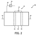
気体流入口12は、酸素含有気体を、出力変調気体放電圧縮ユニット−つまりプラズマポンプ16−へ導く。本発明による方法に非常に適した典型的なプラズマポンプ16が、図2においてより詳細に表されている。
The
プラズマポンプ16は放電チャンバ30を有して良い。放電チャンバ30は、該放電チャンバ30内部で気体放電を行う気体放電装置32を備える。気体放電装置32は、容量結合、誘導結合、表面波結合、及び/又はマイクロ波結合により気体放電を行う結合装置、並びに、該結合装置に交流電流を供するエネルギー源34を有して良い。前記結合装置は2つの電極36と38を有して良い。2つの電極36と38は、容量結合を行うため、気体放電チャンバ30の外部に配置され、かつ炭素で構成されて良い。前記結合装置は放電チャンバ30の外部に配置されることが好ましい。前記結合装置−特に電極36と38−の摩耗を堅調に減少させることができる。しかし、前記結合装置の一部を、少なくとも部分的に放電チャンバ30の内部に配置することも可能である。エネルギー源34の手段によって、2つの電極36と38の間に電圧が印加されることで、気体放電が起こり、かつ、放電チャンバ30の内部でプラズマが生成され得る。交流電流は、長時間にわたるプラズマの維持を可能にする。交流電流の振幅を変化させることによって、プラズマの出力を変調させて良い。
The
放電チャンバ30は、気体流入口40、第1気体流出口42、及び第2気体流出口44をさらに有する。プラズマポンプ16の気体流入口40は、装置10の気体流入口12と接続する。第1気体流出口42は、単純な二方バルブとして設計されうる排出装置46をさらに有して良い。排出装置46は、一方では放電チャンバ30と接続して、他方では大気又は排出気体用の容器と接続する。
The
放電チャンバ30は、導管18とも接続する第2気体流出口44とさらに接続する。気体流入口40と第2気体流出口44を通り抜ける気体の流れを制御するため、流入バルブ48が気体流入口40と接続し、流出バルブ50は第2気体流出口44と接続する(図1を参照のこと)。流入バルブ48及び流出バルブ50として、たとえば逆止弁又は二方弁が用いられても良い。逆止弁は、制御が不要なため好ましい。流入バルブ48と流出バルブ50の動作を、出力変調気体放電に適合させることによって、特定の方向を有する気体流を生成することができる。
The
上述のように放電チャンバ30内でプラズマを生成することによって、加圧された酸素含有気体が生成される。放電チャンバ30内での圧力は、プラズマの高出力動作中に増大し、プラズマの低出力動作中に減少して良い。圧力スイングは、放電チャンバ30内での出力調節放電を実行することによって行われて良い。
By generating plasma in the
以降では、プラズマポンプ16の動作について、例示によってより詳細に説明する。
Hereinafter, the operation of the
第1段階では、プラズマポンプ16の動作は、略大気圧−たとえば1[bar]−で、かつ略室温−たとえば300K−で開始される。このとき、排出装置46、流入バルブ48、及び流出バルブ50は閉じられている。放電チャンバ30内部の高出力プラズマが生成及び維持されることで、温度が上昇する。放電チャンバ30は周囲の空気に対して閉じられているため、プラズマポンプ16の放電チャンバ30内の酸素含有気体は圧縮される。よって典型的には、プラズマによって生じる最大900Kまでの気体の温度上昇により、圧力は最大3[bar]にまで上昇しうる。流出バルブ50を開くことによって、放電チャンバ30内の酸素含有気体は、導管18内を流れることによってしか放電チャンバ30を飛び出すことができないので、放電チャンバ30内で2100Kの範囲までのさらなる高温で一定の圧力となる。ある間隔後、第3段階では、気体排出装置46は、周囲の空気に対して開かれて良い。この状態の間、放電チャンバ30での圧力は大気圧にまで減少し、温度は約1550Kにまで上昇する。ある間隔後、放電出力は、顕著に減少するか、又はオフ状態に切り換えられる。それにより気体の温度は、略室温−たとえば300K−にまで減少する。このとき新鮮な酸素含有気体が、気体流入口12と流入口40を介して放電チャンバ30へ流入して良い。
In the first stage, the operation of the
さらなる時間間隔後、サイクルは完了する。継続するには、プラズマポンプ16は、再度第1段階で開始される。プラズマがオフ状態に切り換えられない場合、以降の段階でのプラズマの点火は省略されて良い。
After a further time interval, the cycle is complete. To continue, the
プラズマポンプ16は、各段階同士が重なることなく動作して良い。あるいはその代わりにプラズマポンプ16は、1つ以上の段階が重なった状態で動作しても良い。
The
プラズマ燃焼中での気体の温度は、上述したように非常に高温で良い。たとえ、プラズマポンプ16の壁の温度が、中心軸に対して減少するような温度分布が存在するとしても、プラズマポンプの壁材料として石英ガラス又はアルミニウム酸化物のような温度安定性を有する材料を用いることは有利である。
The gas temperature during plasma combustion may be very high as described above. Even if there is a temperature distribution such that the temperature of the wall of the
一般的には、プラズマポンプ16のためのエネルギー入力はかなり小さくても十分である。詳細には、温度及び膜の条件に依存して、100W〜350Wの電力入力で十分である。この範囲の電力入力は、在宅医療用途に非常に適している。
In general, the energy input for the
エネルギー源34は、300Hzの周波数で可変出力の方形波電流Iを供給して良い。つまり300Hzの駆動周波数での電流の2乗平均平方根(rms)値Imeanは、t=50msよりも大きな時間スケールで変化して良い。最大数アンペアの電流I mean 及び数百kWの出力が、電子駆動装置により可能である。エネルギー源10はまた、気体の絶縁破壊/プラズマの点火を実現するため、開始段階で最大20kVのピーク電圧を供給する。
The
上述のサイクルで動作する際、プラズマポンプ16は気体ポンプとして機能する。たとえプラズマポンプ16が異なるサイクルで動作するとしても、プラズマポンプ16は、動作サイクルの周波数が高いため、直接かつ連続的に流れる酸素含有気体を生成することができる。
When operating in the above cycle, the
連続流をさらに支持するため、流出バルブ50の下流に気体貯蔵容器52を供することが好ましい。気体貯蔵容器52内部へ放電チャンバ30からの酸素含有気体を押し込み、好適には、貯蔵容器用バルブ54又はオリフィスを供することによって気体貯蔵容器の下流での流れの抵抗を増大させることによって、気体貯蔵容器52内部での超過圧力が生成されて良い。(略)一定の超過圧力は、導管18内での酸素含有気体の(略)連続流を生成するのに用いられて良い。
In order to further support the continuous flow, it is preferable to provide a
メンブレンユニット22の上流では、バルブが供されて良い。前記バルブは、貯蔵容器のバルブ54であっても良いし、又は追加のバルブであっても良い。酸素含有気体の圧力が不十分であるときには、このバルブは導管18を閉じても良い。上記とは対照的に、十分高い圧力が実現されるときには、そのバルブは導管18を開いても良い。よって2.5[bar]以上の圧力−特に5[bar]の圧力−で、バルブが開くことで、酸素含有気体はメンブレンユニット22へ導かれる。
A valve may be provided upstream of the
図3はメンブレンユニット22の断面像を表している。メンブレンユニット22は任意の形状であってもよい。しかしチューブ状のメンブレンユニット22は特に有利である。チューブ状のメンブレンユニット22の内部では、メンブレンユニット22は内側導管56を有する。内側導管56は、流体が流れるように導管18と連通し、かつ酸素含有気体が、メンブレンユニット22へ流入することを可能にする。内側導管56は、その外部では第1面と第2面を有する無機膜58によって制限される。第1面は、内側導管56つまりはプラズマポンプ16の方を向く。他方第2面は、外側導管60の方を向く。外側導管60は、その内側では無機膜58によって制限され、その外側では内側筐体62によって制限される。内側筐体62は、高温耐性の材料−たとえば石英ガラス又はセラミックのアルミニウム酸化物−で作られたチューブであって良い。外側導管60の目的は、分離された酸素を、メンブレンユニット22から取り出すように流すこと、つまりは、流体を流すように導管24と連通することである。内側筐体60の外側には、断熱体64が供される。これは好適には、内側筐体62と外側筐体66との間に供される真空であって良い。この場合では、十分な断熱が実現されるように、内側筐体62と外側筐体66との間の距離を非常に短くすることが好ましい。しかし断熱体64は、十分な断熱効果を実現する、従来技術から既知の任意の種類の断熱体であっても良い。外側筐体66は、断熱をさらに改善する、たとえばアルミニウムに基づく熱シールドとして設計されても良い。このことは実際、装置10のエネルギー効率を改善し、コスト節約となる。
FIG. 3 shows a cross-sectional image of the
戻って無機膜58を参照すると、無機膜58の目的は、酸素を残余分の流れ−つまり酸素含有気体の残りの成分−から分離する、つまり酸素の流れ−これは有利となるように100%純粋な酸素の流れである−を供することである。大抵の場合、特に酸素含有気体として空気が用いられるときには、主な残りの成分は窒素である。よって十分な分離結果を得るため、無機膜58は非常に密であることが重要である。密な無機膜58は、酸素を透過するが、他の気体−特に窒素−を厳密又は少なくとも実質的に透過しない膜である。
Referring back to the
これらの特性を実現するため、無機膜58は、選ばれた無機酸化物の化合物を有する固体セラミックの膜であってよい。好適な無機膜は主として、ペロブスカイト結晶構造又は蛍石結晶構造に基づく。例として、ペロブスカイト関連材料であるBa0.5Sr0.5Co0.5Fe0.2O3-δ(BSCF)は非常に適している。これらの種類の無機膜が、室温では全ての気体を完全に透過させないが、昇温するように加熱されるときに酸素分子を透過させるのは、これらの種類の無機膜の一般的な特性である。主として、ほんの小さなサイズの膜という条件で良好な酸素の流れを実現するには、700Kよりも高い温度が必要である。たとえば上述のBSCFは、1275Kで13ml/(cm2・分)の酸素流を実現することができる。このとき膜の厚さはわずか0.2mmで十分である。
In order to realize these characteristics, the
無機膜は、純粋な酸素伝導膜又は混合イオン伝導膜のいずれかであってよい。一般的に力は、酸素が、膜を通り抜けて輸送されるように印加されなければならない。これは電子の力であってよい。しかし酸素は、無機膜58の第1面と第2面との間での圧力差によって、無機膜58を通り抜けることが好ましい。
The inorganic membrane may be either a pure oxygen conducting membrane or a mixed ion conducting membrane. In general, force must be applied so that oxygen is transported through the membrane. This may be the power of electrons. However, oxygen preferably passes through the
プラズマポンプ16内で酸素含有気体を圧縮することで、同時に、無機膜58の第1面と第2面との間に圧力差が生じる。この効果のため、第1面での酸素の分圧が増大することで、酸素は、密な無機膜58を通り抜けるように流れることが可能となる。この流れは、無機膜58の第1面での圧力を増大させる代わりに又はそれに加えて、無機膜58の第2面での圧力を減少させることによってさらに改善されてよい。極限条件下では、膜58を通り抜ける十分高い酸素の流れを与えるように、無機膜58の第2面に真空が供されて良い。
By compressing the oxygen-containing gas in the
第2面での圧力を減少させることなく、無機膜58の上流、つまり無機膜58の第1面で2.5[bar]以上の圧力を利用することが好ましい。このとき、5[bar]以下の範囲に属する圧力を利用することは特に好ましい。無機膜58の温度及び無機膜58の寸法に依存して、大気圧−たとえば1[bar]−と比較して穏やかに上昇する酸素流が、流出口28で実現されて良い。これは、酸素含有気体の圧力を従来技術に対してかなり減少させることにより実現することができる。本発明による圧力の範囲は在宅医療用途に特に適している。
It is preferable to use a pressure of 2.5 [bar] or more upstream of the
無機膜58が、上述した条件に耐えるのに十分な程度に安定でなければならないことは明らかである。このことは、無機膜58を非常に小さなサイズ又は厚さで形成することが好ましいため、特に重要である。特に無機膜58の第1面と第2面との間での圧力勾配を拡張することによって、無機膜58を支持体上に固定することが有利となりうる。支持体は、有孔性膜−特に粗いフィルタとして用いられるような厚い無機膜−として形成されて良い。この場合上述の有孔性膜は、気体を透過し、かつ酸素に対する選択性を有していない膜である。これにより、無機膜58自体をより安定に形成するという要件を課すことなく無機膜58の安定性を改善することが可能となる。これは、無機膜58よりもはるかに安価なものである安定な成形部品が膜の支持体であるので、さらにコストを削減する。
Obviously, the
上述したように、十分な酸素の透過性を実現するには、無機膜58を加熱することが重要である。本発明によると、これは、容易かつ単純に実現される。酸素含有気体を圧縮するためにプラズマポンプ16を供するため、圧縮された気体は、同時に、無機膜58をその動作温度にまで加熱するのに十分な高さの範囲の温度にまで加熱される。典型的な温度範囲は700K以上である。酸素含有気体つまりは無機膜58を900K〜1300Kの範囲にまで加熱することは特に好ましい。これらの温度範囲では、非常に適切な酸素流を実現することができる。
As described above, it is important to heat the
酸素含有気体を圧縮及び加熱するためのプラズマポンプ16を、酸素を残余分の流れから分離するための無機膜58とともに組み合わせることは、故に、装置10のエネルギー効率を向上させる。酸素含有気体ひいては無機膜を加熱するための更なる手段を設ける必要はない。これは、本発明による装置10のコストを削減し、さらにサイズと重さの特性を改善する。これは、在宅医療用途にとって特に有利である。さらに装置10は、プラズマポンプ16内で発生する高温によって、酸素含有気体が殺菌されるため、一種の「自己洗浄」型である。これは、生成された酸素が殺菌されるという他の利点を有する。これは、多くの用途にとって好ましいことである。
Combining the
図1に戻ると、メンブレンユニット22は、一の面で内側導管56と接続して、他の面で大気と接続可能な流出口68をさらに有する。流出口68を介して、酸素含有量の減少した気体−特に窒素−がメンブレンユニット22を飛び出す。これは、メンブレンユニット22の排出気体である。流出口68は他のバルブ70を有して良い。他のバルブ70は特に、内側導管56内部に圧力が与えられる場合に有利である。
Returning to FIG. 1, the
メンブレンユニット22の下流では、逆止弁のような他のバルブを有しうる導管24は、流出口28と接続する。流出口28にはマウスピース72が備えられて良い。それにより生成された酸素を直接投与することが可能となる。よって、純粋な酸素の十分な流れを得るため、追加のバルブ又は小さな圧縮装置が供されてもよい。導管24の下流であるが、流出口28の上流では、冷却装置26が任意で供されてよい。冷却装置26の冷却は、(換気装置等を用いた)周囲の空気を用いた強制空気流によって実現されてよい。冷却は必要となりうる。その理由は、酸素は依然として無機膜58の下流で高温であり、かつ、多くの用途にとって生成された酸素を冷却する−典型的な場合では室温に冷却する−ことは有利であるためである。しかし酸素を冷却しないことも有利になりうる。その理由は、一部の酸素に基づいた治療は、高温の酸素を利用することによって、より効率的となるからである。
Downstream of the
Claims (12)
放電チャンバ内でプラズマを生成することにより前記酸素含有気体を加熱及び圧縮する工程;
前記の加熱及び圧縮された酸素含有気体を、導管を介して、密な無機膜の第1面へ案内することで、前記酸素含有気体によって酸素を透過させる温度にまで前記無機膜を加熱する工程;並びに、
前記無機膜の第1面と第2面との間で圧力差を発生させる工程;
を有し、
前記無機膜を通り抜ける酸素の流れが生成されることで、前記酸素含有気体から前記酸素が分離される、
方法。 A method for separating oxygen from an oxygen-containing gas comprising:
Heating and compressing the oxygen-containing gas by generating plasma in a discharge chamber;
A step of heating the inorganic film to a temperature at which oxygen is permeated by the oxygen-containing gas by guiding the heated and compressed oxygen-containing gas to the first surface of the dense inorganic film through a conduit. As well as
Generating a pressure difference between the first surface and the second surface of the inorganic film;
Have
The oxygen is separated from the oxygen-containing gas by generating a flow of oxygen through the inorganic membrane;
Method.
前記放電チャンバとメンブレンユニットは、前記の圧縮及び加熱された酸素含有気体を、前記放電チャンバから前記メンブレンユニットへ導く導管を介して接続し、
前記密な無機膜は、前記酸素含有気体から酸素を分離する、
装置。 An oxygen separation apparatus having a discharge chamber for compressing and heating an oxygen-containing gas by generating plasma, and a membrane unit having a dense inorganic membrane,
The discharge chamber and the membrane unit, the compression and heated oxygen-containing gas, and connect the discharge chamber via the guide Kushirube tube the membrane unit,
The dense inorganic film, it separates the oxygen from the oxygen-containing gas,
apparatus.
Applications Claiming Priority (3)
| Application Number | Priority Date | Filing Date | Title |
|---|---|---|---|
| EP09179682 | 2009-12-17 | ||
| EP09179682.1 | 2009-12-17 | ||
| PCT/IB2010/055787 WO2011073889A1 (en) | 2009-12-17 | 2010-12-14 | Oxygen separation method and system with a plasma pump and a membrane |
Publications (3)
| Publication Number | Publication Date |
|---|---|
| JP2013514123A JP2013514123A (en) | 2013-04-25 |
| JP2013514123A5 JP2013514123A5 (en) | 2017-01-12 |
| JP6096513B2 true JP6096513B2 (en) | 2017-03-15 |
Family
ID=43837903
Family Applications (1)
| Application Number | Title | Priority Date | Filing Date |
|---|---|---|---|
| JP2012543966A Active JP6096513B2 (en) | 2009-12-17 | 2010-12-14 | Plasma pump and membrane oxygen separation method and system |
Country Status (5)
| Country | Link |
|---|---|
| US (1) | US8696795B2 (en) |
| EP (1) | EP2512635B1 (en) |
| JP (1) | JP6096513B2 (en) |
| CN (1) | CN102753251B (en) |
| WO (1) | WO2011073889A1 (en) |
Families Citing this family (12)
| Publication number | Priority date | Publication date | Assignee | Title |
|---|---|---|---|---|
| KR101805873B1 (en) | 2011-08-03 | 2018-01-10 | 한화케미칼 주식회사 | A nanoparticles of surface-modified with monosaccharide phosphate or monosaccharide phosphate derivatives, its colloidal solution and use thereof |
| JP5723978B2 (en) | 2010-08-05 | 2015-05-27 | ハンファ ケミカル コーポレーション | Method for producing extremely small and uniform iron oxide-based paramagnetic nanoparticles and MRIT1 contrast agent using the same |
| CN103124689B (en) * | 2010-09-22 | 2016-03-16 | 皇家飞利浦电子股份有限公司 | Produce oxygen and nitric oxide production method and apparatus |
| CN103717291B (en) | 2011-04-28 | 2016-08-17 | 皇家飞利浦有限公司 | For the method and apparatus producing oxygen |
| US20150097485A1 (en) * | 2013-10-08 | 2015-04-09 | XEI Scientific Inc. | Method and apparatus for plasma ignition in high vacuum chambers |
| DE102014115849A1 (en) * | 2014-10-30 | 2016-05-04 | Fraunhofer-Gesellschaft zur Förderung der angewandten Forschung e.V. | Method and arrangement for generating and thermally compressing oxygen |
| US11247015B2 (en) | 2015-03-24 | 2022-02-15 | Ventec Life Systems, Inc. | Ventilator with integrated oxygen production |
| US10245406B2 (en) | 2015-03-24 | 2019-04-02 | Ventec Life Systems, Inc. | Ventilator with integrated oxygen production |
| US10773049B2 (en) | 2016-06-21 | 2020-09-15 | Ventec Life Systems, Inc. | Cough-assist systems with humidifier bypass |
| CA3100163A1 (en) | 2018-05-13 | 2019-11-21 | Samir Saleh AHMAD | Portable medical ventilator system using portable oxygen concentrators |
| FR3093926B1 (en) * | 2019-03-22 | 2022-10-28 | Air Liquide | Apparatus and installation for supplying a gas mixture to a patient |
| CN112999985B (en) * | 2019-12-20 | 2023-08-25 | 南京工业大学 | Method for strengthening oxygen permeation process of mixed conductor film by using plasma |
Family Cites Families (23)
| Publication number | Priority date | Publication date | Assignee | Title |
|---|---|---|---|---|
| SE434676B (en) * | 1981-10-22 | 1984-08-06 | Skf Steel Eng Ab | SET AND DEVICE FOR HEATING OF INDUSTRIAL ENDAL PROCESS AIR |
| US4560394A (en) * | 1981-12-18 | 1985-12-24 | The Garrett Corporation | Oxygen enrichment system |
| EP0164025B1 (en) * | 1984-05-24 | 1989-02-01 | TERUMO KABUSHIKI KAISHA trading as TERUMO CORPORATION | Hollow fiber membrane type oxygenator and method for manufacturing same |
| US4625092A (en) * | 1984-11-30 | 1986-11-25 | Plasma Energy Corporation | Plasma arc bulk air heating apparatus |
| WO1990007372A1 (en) * | 1986-10-27 | 1990-07-12 | Richard Alan Sauer | Process for membrane separation of gas mixtures |
| US5355764A (en) * | 1992-05-04 | 1994-10-18 | Fmc Corporation | Plasma actuated ignition and distribution pump |
| ES2173224T3 (en) * | 1995-06-07 | 2002-10-16 | Air Prod & Chem | OXYGEN PRODUCTION WITH MEMBERS OF ION TRANSPORTATION AND ENERGY RECOVERY. |
| CA2353392C (en) * | 1998-12-04 | 2010-10-05 | Cabot Corporation | Process for production of carbon black |
| US20020100836A1 (en) * | 2001-01-31 | 2002-08-01 | Hunt Robert Daniel | Hydrogen and oxygen battery, or hudrogen and oxygen to fire a combustion engine and/or for commerce. |
| JP3891834B2 (en) * | 2001-12-04 | 2007-03-14 | 大陽日酸株式会社 | Gas supply method and apparatus |
| AU2003241867A1 (en) * | 2002-05-31 | 2004-01-19 | Ube Industries, Ltd. | Fuel cell-use humidifier |
| US6667475B1 (en) * | 2003-01-08 | 2003-12-23 | Applied Materials, Inc. | Method and apparatus for cleaning an analytical instrument while operating the analytical instrument |
| GB2397303B (en) * | 2003-01-17 | 2007-04-04 | Smartmembrane Corp | Gas separation membranes |
| US7088106B2 (en) | 2003-06-27 | 2006-08-08 | University Of Wyoming | Device and method for the measurement of gas permeability through membranes |
| US7384619B2 (en) | 2003-06-30 | 2008-06-10 | Bar-Gadda, Llc | Method for generating hydrogen from water or steam in a plasma |
| US7694674B2 (en) | 2004-09-21 | 2010-04-13 | Carleton Life Support Systems, Inc. | Oxygen generator with storage and conservation modes |
| US7763097B2 (en) * | 2006-06-08 | 2010-07-27 | University of Pittsburgh—of the Commonwealth System of Higher Education | Devices, systems and methods for reducing the concentration of a chemical entity in fluids |
| EP2482968A1 (en) * | 2009-09-30 | 2012-08-08 | Koninklijke Philips Electronics N.V. | Gas concentration arrangement |
| EP2516329B1 (en) * | 2009-12-23 | 2015-07-29 | Koninklijke Philips N.V. | Method for generating nitric oxide |
| CN102740958A (en) * | 2010-02-03 | 2012-10-17 | 皇家飞利浦电子股份有限公司 | Membrane for oxygen generation |
| US8999039B2 (en) * | 2010-03-05 | 2015-04-07 | Koninklijke Philips N.V. | Oxygen separation membrane |
| CN103124689B (en) * | 2010-09-22 | 2016-03-16 | 皇家飞利浦电子股份有限公司 | Produce oxygen and nitric oxide production method and apparatus |
| EP2629880B1 (en) * | 2010-10-22 | 2017-04-05 | Koninklijke Philips N.V. | Arrangement and method for separating oxygen |
-
2010
- 2010-12-14 JP JP2012543966A patent/JP6096513B2/en active Active
- 2010-12-14 CN CN201080056788.8A patent/CN102753251B/en active Active
- 2010-12-14 WO PCT/IB2010/055787 patent/WO2011073889A1/en active Application Filing
- 2010-12-14 US US13/515,525 patent/US8696795B2/en active Active
- 2010-12-14 EP EP10809076.2A patent/EP2512635B1/en active Active
Also Published As
| Publication number | Publication date |
|---|---|
| EP2512635A1 (en) | 2012-10-24 |
| CN102753251A (en) | 2012-10-24 |
| EP2512635B1 (en) | 2016-03-16 |
| US8696795B2 (en) | 2014-04-15 |
| WO2011073889A1 (en) | 2011-06-23 |
| JP2013514123A (en) | 2013-04-25 |
| US20120247329A1 (en) | 2012-10-04 |
| CN102753251B (en) | 2016-11-16 |
Similar Documents
| Publication | Publication Date | Title |
|---|---|---|
| JP6096513B2 (en) | Plasma pump and membrane oxygen separation method and system | |
| JP2013514123A5 (en) | ||
| JP2014500136A (en) | Oxygen separator and method | |
| JP2014500136A5 (en) | ||
| JP5357264B2 (en) | Oxygen concentrator | |
| JP5848780B2 (en) | Method and configuration for generating oxygen | |
| JP5888908B2 (en) | Concentration method of ozone gas | |
| JP2013521114A (en) | Oxygen separation membrane | |
| CN115916311A (en) | Power management in portable oxygen concentrator | |
| KR20210050209A (en) | High Purity Oxygen Generator | |
| AU2010302301B2 (en) | Gas concentration arrangement | |
| US20170101314A1 (en) | Method and arrangement for generating oxygen | |
| CN103124689B (en) | Produce oxygen and nitric oxide production method and apparatus | |
| JP5584887B2 (en) | Ozone gas concentration method and apparatus | |
| JP6081760B2 (en) | Oxygen concentrator | |
| JP2014522361A5 (en) | ||
| JP5193537B2 (en) | Oxygen concentrator | |
| JP5431662B2 (en) | Oxygen concentrator | |
| JP2005006732A (en) | Oxygen concentrator | |
| JP2009254502A (en) | Oxygen concentrator | |
| KR20110068150A (en) | Oxygen supply apparatus including oxygen separation membrane |
Legal Events
| Date | Code | Title | Description |
|---|---|---|---|
| A621 | Written request for application examination |
Free format text: JAPANESE INTERMEDIATE CODE: A621 Effective date: 20131211 |
|
| A131 | Notification of reasons for refusal |
Free format text: JAPANESE INTERMEDIATE CODE: A131 Effective date: 20140924 |
|
| A977 | Report on retrieval |
Free format text: JAPANESE INTERMEDIATE CODE: A971007 Effective date: 20140926 |
|
| A521 | Request for written amendment filed |
Free format text: JAPANESE INTERMEDIATE CODE: A523 Effective date: 20141204 |
|
| A02 | Decision of refusal |
Free format text: JAPANESE INTERMEDIATE CODE: A02 Effective date: 20150623 |
|
| A521 | Request for written amendment filed |
Free format text: JAPANESE INTERMEDIATE CODE: A523 Effective date: 20151019 |
|
| A911 | Transfer to examiner for re-examination before appeal (zenchi) |
Free format text: JAPANESE INTERMEDIATE CODE: A911 Effective date: 20151110 |
|
| A912 | Re-examination (zenchi) completed and case transferred to appeal board |
Free format text: JAPANESE INTERMEDIATE CODE: A912 Effective date: 20160115 |
|
| A524 | Written submission of copy of amendment under article 19 pct |
Free format text: JAPANESE INTERMEDIATE CODE: A524 Effective date: 20161125 |
|
| A61 | First payment of annual fees (during grant procedure) |
Free format text: JAPANESE INTERMEDIATE CODE: A61 Effective date: 20170216 |
|
| R150 | Certificate of patent or registration of utility model |
Ref document number: 6096513 Country of ref document: JP Free format text: JAPANESE INTERMEDIATE CODE: R150 |
|
| R250 | Receipt of annual fees |
Free format text: JAPANESE INTERMEDIATE CODE: R250 |
|
| R250 | Receipt of annual fees |
Free format text: JAPANESE INTERMEDIATE CODE: R250 |
|
| R250 | Receipt of annual fees |
Free format text: JAPANESE INTERMEDIATE CODE: R250 |
|
| R250 | Receipt of annual fees |
Free format text: JAPANESE INTERMEDIATE CODE: R250 |
|
| R250 | Receipt of annual fees |
Free format text: JAPANESE INTERMEDIATE CODE: R250 |