EP2512635B1 - Oxygen separation method and system with a plasma pump and a membrane - Google Patents
Oxygen separation method and system with a plasma pump and a membrane Download PDFInfo
- Publication number
- EP2512635B1 EP2512635B1 EP10809076.2A EP10809076A EP2512635B1 EP 2512635 B1 EP2512635 B1 EP 2512635B1 EP 10809076 A EP10809076 A EP 10809076A EP 2512635 B1 EP2512635 B1 EP 2512635B1
- Authority
- EP
- European Patent Office
- Prior art keywords
- oxygen
- membrane
- containing gas
- oxygen containing
- arrangement
- Prior art date
- Legal status (The legal status is an assumption and is not a legal conclusion. Google has not performed a legal analysis and makes no representation as to the accuracy of the status listed.)
- Active
Links
- QVGXLLKOCUKJST-UHFFFAOYSA-N atomic oxygen Chemical compound [O] QVGXLLKOCUKJST-UHFFFAOYSA-N 0.000 title claims description 149
- 239000001301 oxygen Substances 0.000 title claims description 149
- 229910052760 oxygen Inorganic materials 0.000 title claims description 149
- 239000012528 membrane Substances 0.000 title claims description 114
- 238000000926 separation method Methods 0.000 title claims description 11
- 239000007789 gas Substances 0.000 claims description 118
- 238000000034 method Methods 0.000 claims description 19
- MYMOFIZGZYHOMD-UHFFFAOYSA-N Dioxygen Chemical compound O=O MYMOFIZGZYHOMD-UHFFFAOYSA-N 0.000 claims description 14
- 238000010438 heat treatment Methods 0.000 claims description 10
- 238000002955 isolation Methods 0.000 claims description 10
- IJGRMHOSHXDMSA-UHFFFAOYSA-N Atomic nitrogen Chemical compound N#N IJGRMHOSHXDMSA-UHFFFAOYSA-N 0.000 description 11
- 230000001965 increasing effect Effects 0.000 description 10
- 230000008878 coupling Effects 0.000 description 8
- 238000010168 coupling process Methods 0.000 description 8
- 238000005859 coupling reaction Methods 0.000 description 8
- 239000003570 air Substances 0.000 description 7
- 229910052757 nitrogen Inorganic materials 0.000 description 6
- 230000008901 benefit Effects 0.000 description 5
- 239000000470 constituent Substances 0.000 description 5
- 238000002640 oxygen therapy Methods 0.000 description 5
- 230000003247 decreasing effect Effects 0.000 description 4
- 230000000694 effects Effects 0.000 description 4
- 239000000463 material Substances 0.000 description 4
- 239000012466 permeate Substances 0.000 description 4
- 230000035699 permeability Effects 0.000 description 3
- 230000008569 process Effects 0.000 description 3
- 239000000047 product Substances 0.000 description 3
- 238000004659 sterilization and disinfection Methods 0.000 description 3
- 230000001225 therapeutic effect Effects 0.000 description 3
- 238000011144 upstream manufacturing Methods 0.000 description 3
- XLYOFNOQVPJJNP-UHFFFAOYSA-N water Substances O XLYOFNOQVPJJNP-UHFFFAOYSA-N 0.000 description 3
- UFHFLCQGNIYNRP-UHFFFAOYSA-N Hydrogen Chemical compound [H][H] UFHFLCQGNIYNRP-UHFFFAOYSA-N 0.000 description 2
- 206010021143 Hypoxia Diseases 0.000 description 2
- VYPSYNLAJGMNEJ-UHFFFAOYSA-N Silicium dioxide Chemical compound O=[Si]=O VYPSYNLAJGMNEJ-UHFFFAOYSA-N 0.000 description 2
- 230000015572 biosynthetic process Effects 0.000 description 2
- 239000000919 ceramic Substances 0.000 description 2
- 230000006835 compression Effects 0.000 description 2
- 238000007906 compression Methods 0.000 description 2
- 238000001816 cooling Methods 0.000 description 2
- 239000001257 hydrogen Substances 0.000 description 2
- 229910052739 hydrogen Inorganic materials 0.000 description 2
- 238000012423 maintenance Methods 0.000 description 2
- 238000004519 manufacturing process Methods 0.000 description 2
- 230000009467 reduction Effects 0.000 description 2
- 239000012465 retentate Substances 0.000 description 2
- 238000003860 storage Methods 0.000 description 2
- PNEYBMLMFCGWSK-UHFFFAOYSA-N Alumina Chemical class [O-2].[O-2].[O-2].[Al+3].[Al+3] PNEYBMLMFCGWSK-UHFFFAOYSA-N 0.000 description 1
- 229910002714 Ba0.5Sr0.5 Inorganic materials 0.000 description 1
- OKTJSMMVPCPJKN-UHFFFAOYSA-N Carbon Chemical compound [C] OKTJSMMVPCPJKN-UHFFFAOYSA-N 0.000 description 1
- 208000006545 Chronic Obstructive Pulmonary Disease Diseases 0.000 description 1
- 229910000831 Steel Inorganic materials 0.000 description 1
- 230000001154 acute effect Effects 0.000 description 1
- 229910052782 aluminium Inorganic materials 0.000 description 1
- XAGFODPZIPBFFR-UHFFFAOYSA-N aluminium Chemical compound [Al] XAGFODPZIPBFFR-UHFFFAOYSA-N 0.000 description 1
- 239000012080 ambient air Substances 0.000 description 1
- 230000009286 beneficial effect Effects 0.000 description 1
- WUKWITHWXAAZEY-UHFFFAOYSA-L calcium difluoride Chemical compound [F-].[F-].[Ca+2] WUKWITHWXAAZEY-UHFFFAOYSA-L 0.000 description 1
- 229910052799 carbon Inorganic materials 0.000 description 1
- 230000015556 catabolic process Effects 0.000 description 1
- 230000019522 cellular metabolic process Effects 0.000 description 1
- 230000001684 chronic effect Effects 0.000 description 1
- 238000004140 cleaning Methods 0.000 description 1
- 238000002485 combustion reaction Methods 0.000 description 1
- 150000001875 compounds Chemical class 0.000 description 1
- 239000013078 crystal Substances 0.000 description 1
- 230000001419 dependent effect Effects 0.000 description 1
- 238000003795 desorption Methods 0.000 description 1
- 238000010586 diagram Methods 0.000 description 1
- 238000009826 distribution Methods 0.000 description 1
- 239000010436 fluorite Substances 0.000 description 1
- 239000000446 fuel Substances 0.000 description 1
- 230000036044 hypoxaemia Effects 0.000 description 1
- 230000007954 hypoxia Effects 0.000 description 1
- 230000001939 inductive effect Effects 0.000 description 1
- 239000011261 inert gas Substances 0.000 description 1
- 229910052809 inorganic oxide Inorganic materials 0.000 description 1
- 230000037427 ion transport Effects 0.000 description 1
- 239000007788 liquid Substances 0.000 description 1
- 210000004072 lung Anatomy 0.000 description 1
- 229910052751 metal Inorganic materials 0.000 description 1
- 239000002184 metal Substances 0.000 description 1
- QJGQUHMNIGDVPM-UHFFFAOYSA-N nitrogen group Chemical group [N] QJGQUHMNIGDVPM-UHFFFAOYSA-N 0.000 description 1
- TWNQGVIAIRXVLR-UHFFFAOYSA-N oxo(oxoalumanyloxy)alumane Chemical compound O=[Al]O[Al]=O TWNQGVIAIRXVLR-UHFFFAOYSA-N 0.000 description 1
- 230000035790 physiological processes and functions Effects 0.000 description 1
- 238000003825 pressing Methods 0.000 description 1
- 238000004537 pulping Methods 0.000 description 1
- 230000000306 recurrent effect Effects 0.000 description 1
- 239000007787 solid Substances 0.000 description 1
- 239000010959 steel Substances 0.000 description 1
- 230000001954 sterilising effect Effects 0.000 description 1
- 230000002459 sustained effect Effects 0.000 description 1
- 230000002195 synergetic effect Effects 0.000 description 1
- 238000002560 therapeutic procedure Methods 0.000 description 1
- 230000000287 tissue oxygenation Effects 0.000 description 1
- 239000002023 wood Substances 0.000 description 1
Images

Classifications
-
- B—PERFORMING OPERATIONS; TRANSPORTING
- B01—PHYSICAL OR CHEMICAL PROCESSES OR APPARATUS IN GENERAL
- B01D—SEPARATION
- B01D53/00—Separation of gases or vapours; Recovering vapours of volatile solvents from gases; Chemical or biological purification of waste gases, e.g. engine exhaust gases, smoke, fumes, flue gases, aerosols
- B01D53/22—Separation of gases or vapours; Recovering vapours of volatile solvents from gases; Chemical or biological purification of waste gases, e.g. engine exhaust gases, smoke, fumes, flue gases, aerosols by diffusion
-
- A—HUMAN NECESSITIES
- A61—MEDICAL OR VETERINARY SCIENCE; HYGIENE
- A61M—DEVICES FOR INTRODUCING MEDIA INTO, OR ONTO, THE BODY; DEVICES FOR TRANSDUCING BODY MEDIA OR FOR TAKING MEDIA FROM THE BODY; DEVICES FOR PRODUCING OR ENDING SLEEP OR STUPOR
- A61M16/00—Devices for influencing the respiratory system of patients by gas treatment, e.g. mouth-to-mouth respiration; Tracheal tubes
- A61M16/10—Preparation of respiratory gases or vapours
- A61M16/1005—Preparation of respiratory gases or vapours with O2 features or with parameter measurement
- A61M16/101—Preparation of respiratory gases or vapours with O2 features or with parameter measurement using an oxygen concentrator
-
- B—PERFORMING OPERATIONS; TRANSPORTING
- B01—PHYSICAL OR CHEMICAL PROCESSES OR APPARATUS IN GENERAL
- B01D—SEPARATION
- B01D53/00—Separation of gases or vapours; Recovering vapours of volatile solvents from gases; Chemical or biological purification of waste gases, e.g. engine exhaust gases, smoke, fumes, flue gases, aerosols
- B01D53/32—Separation of gases or vapours; Recovering vapours of volatile solvents from gases; Chemical or biological purification of waste gases, e.g. engine exhaust gases, smoke, fumes, flue gases, aerosols by electrical effects other than those provided for in group B01D61/00
- B01D53/323—Separation of gases or vapours; Recovering vapours of volatile solvents from gases; Chemical or biological purification of waste gases, e.g. engine exhaust gases, smoke, fumes, flue gases, aerosols by electrical effects other than those provided for in group B01D61/00 by electrostatic effects or by high-voltage electric fields
-
- C—CHEMISTRY; METALLURGY
- C01—INORGANIC CHEMISTRY
- C01B—NON-METALLIC ELEMENTS; COMPOUNDS THEREOF; METALLOIDS OR COMPOUNDS THEREOF NOT COVERED BY SUBCLASS C01C
- C01B13/00—Oxygen; Ozone; Oxides or hydroxides in general
- C01B13/02—Preparation of oxygen
- C01B13/0229—Purification or separation processes
- C01B13/0248—Physical processing only
- C01B13/0251—Physical processing only by making use of membranes
- C01B13/0255—Physical processing only by making use of membranes characterised by the type of membrane
-
- A—HUMAN NECESSITIES
- A61—MEDICAL OR VETERINARY SCIENCE; HYGIENE
- A61M—DEVICES FOR INTRODUCING MEDIA INTO, OR ONTO, THE BODY; DEVICES FOR TRANSDUCING BODY MEDIA OR FOR TAKING MEDIA FROM THE BODY; DEVICES FOR PRODUCING OR ENDING SLEEP OR STUPOR
- A61M2205/00—General characteristics of the apparatus
- A61M2205/36—General characteristics of the apparatus related to heating or cooling
- A61M2205/3606—General characteristics of the apparatus related to heating or cooling cooled
-
- B—PERFORMING OPERATIONS; TRANSPORTING
- B01—PHYSICAL OR CHEMICAL PROCESSES OR APPARATUS IN GENERAL
- B01D—SEPARATION
- B01D2256/00—Main component in the product gas stream after treatment
- B01D2256/12—Oxygen
-
- B—PERFORMING OPERATIONS; TRANSPORTING
- B01—PHYSICAL OR CHEMICAL PROCESSES OR APPARATUS IN GENERAL
- B01D—SEPARATION
- B01D2257/00—Components to be removed
- B01D2257/10—Single element gases other than halogens
- B01D2257/104—Oxygen
-
- B—PERFORMING OPERATIONS; TRANSPORTING
- B01—PHYSICAL OR CHEMICAL PROCESSES OR APPARATUS IN GENERAL
- B01D—SEPARATION
- B01D2259/00—Type of treatment
- B01D2259/45—Gas separation or purification devices adapted for specific applications
- B01D2259/4533—Gas separation or purification devices adapted for specific applications for medical purposes
-
- C—CHEMISTRY; METALLURGY
- C01—INORGANIC CHEMISTRY
- C01B—NON-METALLIC ELEMENTS; COMPOUNDS THEREOF; METALLOIDS OR COMPOUNDS THEREOF NOT COVERED BY SUBCLASS C01C
- C01B2210/00—Purification or separation of specific gases
- C01B2210/0043—Impurity removed
- C01B2210/0046—Nitrogen
Definitions
- Oxygen therapy is the administration of oxygen as a therapeutic modality. It is widely used for a variety of purposes in both chronic and acute patient care as it is essential for cell metabolism, and in turn, tissue oxygenation is essential for all physiological functions. Oxygen therapy should be used to benefit the patient by increasing the supply of oxygen to the lungs and thereby increasing the availability of oxygen to the body tissues, especially when the patient is suffering from hypoxia and/or hypoxaemia. Oxygen therapy may be used both in applications in hospital or in home care. The main home care application of oxygen therapy is for patients with severe chronic obstructive pulmonary disease (COPD).
- COPD chronic chronic obstructive pulmonary disease
- US2004/265137 A1 is about a method in which water molecules, preferably in the form of steam or water vapor, are introduced into a plasma.
- the plasma causes the water molecules to dissociate into their constituent molecular elements of hydrogen and oxygen.
- the hydrogen and oxygen are separated from each other.
- Various devices maybe employed to effect this separation. Once separated, the molecular components are prevented from recombining with each other or with other elements by using standard separation techniques normally employed for separating dissimilar gaseous species.
- an electronic controller controls the operation of an electrochemical oxygen generating system producing a desired gas.
- the product gas is fed to a storage unit or a regulator and pulsing valve controlling the gas flow to a user.
- a two-stage system combines a low pressure and a high pressure gas generating subsystems.
- the low pressure subsystem uses Integrated Manifold And Tubes (IMAT's) to pump oxygen from ambient air to generate a low-pressure.
- the high pressure subsystem uses IMAT's to pump oxygen to high-pressure oxygen storage devices.
- oxygen containing gas shall refer to any gas which at least partly comprises oxygen.
- the present invention is based on the unexpected finding that a combination of heating and compressing an oxygen containing gas in a plasma pump together with separating the oxygen by an inorganic membrane leads to surprising and very beneficial synergistic effects.
- the oxygen containing gas is compressed and heated in one step.
- the gas which leaves the plasma pump has a sufficiently high temperature to heat the inorganic membrane thereby enabling a sufficiently high oxygen flow through said membrane.
- a plasma pump works with a reduction of noise leading to a considerable increase in convenience, especially in home care applications.
- the convenience is even more improved by the fact that by providing a plasma pump for heating and compressing the oxygen containing gas, the used device has reduced size and weight which is particular advantageous for home care applications.
- swing processes are no longer necessary because nitrogen does not adsorb to the inorganic membrane thereby not limiting the permeability conditions with respect to oxygen.
- air is used as oxygen containing gas. This is especially preferable at home care applications because no special oxygen containing gases have to be stored.
- the oxygen containing gas is heated to a temperature range of ⁇ 900 K and ⁇ 1300 K.
- the inorganic membrane is heated to a sufficiently high temperature to provide adequate permeability properties for oxygen.
- the oxygen is cooled after separation. This enables a direct administration of oxygen to the patient.
- the amount of cooling may thereby be adapted to the specific use. In some applications, it is desirable if the oxygen is cooled down to room temperature whereas some applications are more effective when using oxygen at temperatures being elevated with respect to room temperature.
- the method according to the invention may be achieved by a gas separation arrangement according to the invention, the arrangement comprising a plasma pump for compressing and heating an oxygen containing gas, and a membrane unit with a dense inorganic membrane, wherein the plasma pump and the membrane unit are connected via a conduct being designed to guide the heated and compressed oxygen containing gas from the plasma pump to the membrane unit, and the dense inorganic membrane being designed to separate oxygen from the oxygen containing gas.
- the arrangement comprises a cooler being arranged downstream the membrane unit.
- the cooler enables the generated oxygen to be cooled down to a temperature being applicable for direct administration to a patient.
- a gas reservoir is provided downstream the plasma pump. This enables the formation of a continuous flow of oxygen containing gas and thus of pure oxygen.
- a heat isolation is provided outside an inner housing. This enables a better heat efficiency and reduces the required energy input and thus the costs.
- the heat isolation is designed as a vacuum. This is a special easy and effective way to create a heat isolation.
- FIG. 1 an arrangement 10 for separating oxygen from an oxygen containing gas is schematically shown.
- the arrangement 10 is very well suitable for oxygen therapy e.g. in home care applications.
- the arrangement 10 as well as the method according to the invention is not limited to therapeutic applications, but is furthermore suitable for a all kinds of generation of oxygen.
- it is referred to the oxygen generation in airplanes.
- a voltage could be applied between the two electrodes 36, 38, leading to a gas discharge and to the generation of a plasma inside the discharge chamber 30.
- An alternating current allows to sustain the plasma over time, by changing of the amplitude of the alternating current the power of the plasma can be modulated.
- the discharge chamber 30 further comprises a gas inlet 40, a first gas outlet 42 and a second gas outlet 44.
- the gas inlet 40 of the plasma pump 16 is connected to the gas inlet 12 of the arrangement 10.
- the first gas outlet 42 may further comprise an exhaust device 46 which may be designed as a simple two way valve. It is on one side connected to the discharge chamber 30 and on the other side connected to the atmosphere or a reservoir for exhaust gas.
- the discharge chamber 30 is further connected to the second gas outlet 44 which in turn is connected to the conduct 18.
- an inlet valve 48 is connected with the gas inlet 40 and an outlet valve 50 is connected with the second gas outlet 44 (see fig. 1 ).
- inlet valve 48 and outlet valve 50 non-return valves or two-way valves can be used, for example. Non-return valves are preferred because they do not need controlling.
- the cycle is finished.
- the plasma pump 16 starts again with the first step. If the plasma has not been switched off, igniting the plasma in the following step can be omitted.
- the gas temperatures during burning the plasma may be very high, like described above. Even though there is a temperature distribution leading to the walls of the plasma pump 16 having temperatures being decreased with respect to the central axis, the use of temperature stable materials like quartz glass or aluminum oxides as wall materials of the plasma pump are advantageous.
- a gas reservoir 52 downstream the outlet valve 50.
- an over pressure inside the reservoir 52 can be generated, preferably by increasing the flow resistance downstream the gas reservoir by providing a reservoir valve 54 or, alternatively, an orifice.
- a constant or nearly constant over pressure can be used to generate a continuous or nearly continuous flow of the oxygen containing gas in the conduct 18.
- a a valve may be provided, which may be the reservoir valve 54 or an additional valve. This valve may close the conduct 18, when the pressure of the oxygen containing gas is insufficient. Contrary thereto, the valve may open the conduct 18 when a sufficiently high pressure is reached. Thus, it may be provided that at a pressure of ⁇ 2.5 bars, in particular at 5 bars, the valve opens, and thus guiding the oxygen containing gas to the membrane unit 22.
- the inner housing 62 may be a tube made from a material being resistant against higher temperatures, for example quartz glass or ceramic aluminum oxide.
- the objective of the outer conduct 60 is to conduct the separated oxygen out of the membrane unit 22 and is thus in flow connection with the conduct 24.
- a heat isolation 64 is provided outside the inner housing 60. This may preferably be a vacuum, which is provided between the inner housing 62 and an outer housing 66. It is as well possible to provide an inert gas between the inner housing 62 and the outer housing 66. In this case, it would be preferable to provide a very short distance between the inner housing 62 and the outer housing 66 to achieve a sufficient isolation.
- the isolation 64 may be of any kind known from the state of the art to get a sufficient isolation effect.
- the outer housing 66 may be designed as a thermal shield, for example based on aluminum, to further improve the isolation. This in fact improves the energy efficiency of the arrangement 10 and is thus cost saving.
- the inorganic membrane 58 its objective is to separate the oxygen from the remaining retentate flow, i.e. the remaining constituents of the oxygen containing gas, and thus to provide a flow of oxygen, which advantageously is a flow of 100% pure oxygen.
- the main remaining constituent is nitrogen, especially in the case when air is used as oxygen containing gas.
- a dense inorganic membrane 58 is a membrane being is permeable with respect to oxygen, but being strictly or at least substantially non-permeable for other gases, especially for nitrogen.
- the inorganic membranes may be either pure oxygen conducting membranes or mixed ionic-electronic conducting membranes. Generally, a force has to be applied to cause the oxygen being transferred through the membrane. This may either be an electronic force. However, it is preferred, that the oxygen passes the inorganic membrane 58 due to a pressure difference between the primary and the secondary side of the inorganic membrane 58.
Description
- The invention relates to the field of oxygen separation. More specifically, the invention relates to oxygen separation for therapeutic applications, particularly in the field of home care.
- Oxygen therapy is the administration of oxygen as a therapeutic modality. It is widely used for a variety of purposes in both chronic and acute patient care as it is essential for cell metabolism, and in turn, tissue oxygenation is essential for all physiological functions. Oxygen therapy should be used to benefit the patient by increasing the supply of oxygen to the lungs and thereby increasing the availability of oxygen to the body tissues, especially when the patient is suffering from hypoxia and/or hypoxaemia. Oxygen therapy may be used both in applications in hospital or in home care. The main home care application of oxygen therapy is for patients with severe chronic obstructive pulmonary disease (COPD).
- Oxygen may be administered in a number of ways. A preferable way of oxygen administration is by using a so called on demand generation of oxygen. Referring to this, commercial solutions, so-called oxygen concentrators or separators, respectively, are widely known. These oxygen concentrators mostly separate oxygen from an oxygen containing gas, so that the oxygen is provided on demand, i.e. directly before use. Most known oxygen concentrators require a compressor to compress the oxygen containing gas. Furthermore, oxygen, preferably pure oxygen, has to be generated. Most known oxygen concentrators thus comprise an organic membrane to separate oxygen from the oxygen containing gas.
- The major drawbacks of the known oxygen concentrators are a high costs and a limited convenience with respect to noise. Furthermore, undesired constituents of the oxygen containing gas, mostly nitrogen, are adsorbed on the membrane thereby causing the requirement of a so-called swing process by which the adsorbed gas is desorbed from the membrane. During that desorption step, a separation of oxygen is not possible, because of which two membranes are desired which further increases the costs. Apart from that, the compressors are mostly noisy leading to a decreased convenience especially when the oxygen concentrator is used over night. Furthermore, the generated oxygen is non-sterile, because of which a further measure of disinfection is often desired or necessary.
- Traditional oxygen concentrators are bulky, heavy and require ongoing maintenance by patients and home care providers. Such devices produce noise and heat. Furthermore, a reduction of cost price (a compressor unit comes up with a significant contribution), of recurrent purchase costs and of servicing is desirable.
-
US2004/265137 A1 is about a method in which water molecules, preferably in the form of steam or water vapor, are introduced into a plasma. The plasma causes the water molecules to dissociate into their constituent molecular elements of hydrogen and oxygen. To prevent recombining of the constituent molecular elements, the hydrogen and oxygen are separated from each other. Various devices maybe employed to effect this separation. Once separated, the molecular components are prevented from recombining with each other or with other elements by using standard separation techniques normally employed for separating dissimilar gaseous species. - In
US5753007 A oxygen is recovered from a hot, compressed oxygen-containing gas, preferably air, by an oxygen-selective ion transport membrane system. Hot, pressurized non-permeate gas from the membrane is cooled and useful work is recovered therefrom by expansion at temperatures below the operating temperature of the membrane. The recovered work is used together with the oxygen permeate product in applications such as oxygen-enriched combustion of liquid fuels, wood pulping processes, steel production from scrap in mini-mills, and metal fabrication operations. Oxygen permeate product can be compressed utilizing a gas booster compressor driven by expansion of cooled, pressurized non-permeate gas. - In
WO2006/033896 A2 an electronic controller controls the operation of an electrochemical oxygen generating system producing a desired gas. The product gas is fed to a storage unit or a regulator and pulsing valve controlling the gas flow to a user. A two-stage system combines a low pressure and a high pressure gas generating subsystems. The low pressure subsystem uses Integrated Manifold And Tubes (IMAT's) to pump oxygen from ambient air to generate a low-pressure. The high pressure subsystem uses IMAT's to pump oxygen to high-pressure oxygen storage devices. - The term "dense membrane", as used herein, shall refer to a membrane which is permeable for oxygen but non-permeable for other gases, especially for nitrogen.
- The term "oxygen containing gas", as used herein, shall refer to any gas which at least partly comprises oxygen.
- The term "primary side" of the membrane, as used herein, shall refer to the side of the membrane being directed towards the plasma pump.
- The term "secondary side" of the membrane, as used herein, shall refer to the side of the membrane being directed towards the outlet of the membrane unit.
- It is an object of the invention to provide a method of separating oxygen which is cost-saving, and improves convenience with respect to maintenance and noise.
- This object is achieved by a method of separating oxygen from an oxygen containing gas, said method comprising the steps of: compressing and heating the oxygen containing gas in a plasma pump, guiding the heated and compressed oxygen containing gas to the primary side of a dense inorganic membrane, thereby heating the inorganic membrane by the oxygen containing gas to a temperature at which it is permeable for oxygen, and creating a pressure difference between the primary side and a secondary side of the inorganic membrane, wherein an oxygen flow through the inorganic membrane is created, thereby separating the oxygen from the oxygen containing gas.
- The present invention is based on the unexpected finding that a combination of heating and compressing an oxygen containing gas in a plasma pump together with separating the oxygen by an inorganic membrane leads to surprising and very beneficial synergistic effects.
- By using a plasma pump, the oxygen containing gas is compressed and heated in one step. This leads to the advantage that an additional device for heating the compressed gas or the membrane as such is not required. Contrary thereto, the gas which leaves the plasma pump has a sufficiently high temperature to heat the inorganic membrane thereby enabling a sufficiently high oxygen flow through said membrane. Thus, the generally undesired effect, that, by compressing a gas with a plasma pump, the compressed oxygen containing gas has an elevated temperature, is thus directly very well applicable in combination with an inorganic membrane.
- Furthermore, a plasma pump works with a reduction of noise leading to a considerable increase in convenience, especially in home care applications. The convenience is even more improved by the fact that by providing a plasma pump for heating and compressing the oxygen containing gas, the used device has reduced size and weight which is particular advantageous for home care applications.
- Additionally, by using an arrangement with both a plasma pump and an inorganic membrane, oxygen is separated with lower costs due to the fact that the arrangement as such may be designed much cheaper, and furthermore, the energy efficiency is improved compared to the methods known from the state of the art.
- A further advantage of the method according to the invention is the generation of sterile oxygen. Additional disinfection or sterilization steps are not necessary. According to the invention, an on demand generation of sterile oxygen is provided.
- Additionally, swing processes are no longer necessary because nitrogen does not adsorb to the inorganic membrane thereby not limiting the permeability conditions with respect to oxygen.
- By using a plasma pump instead of a compressor known from the state of the art an increase with respect to cost price, servicing and noise may thus be achieved.
- In a preferred embodiment of the invention, air is used as oxygen containing gas. This is especially preferable at home care applications because no special oxygen containing gases have to be stored.
- In a further embodiment, the oxygen containing gas is compressed to a range of ≥ 2.5 bars to directly come up with an oxygen pressure above atmospheric pressure on the secondary side. This pressure may be enough to get a sufficiently high oxygen flow through the inorganic membrane providing an adequate flow of generated pure oxygen. Referring to this, it is particularly advantageous, if the oxygen containing gas is compressed to a range of 5 bars.
- In a further embodiment, the oxygen containing gas is heated to a temperature range of ≥ 900 K and ≤ 1300 K. By providing an accordingly heated oxygen containing gas, the inorganic membrane is heated to a sufficiently high temperature to provide adequate permeability properties for oxygen.
- In a further embodiment, the oxygen is cooled after separation. This enables a direct administration of oxygen to the patient. The amount of cooling may thereby be adapted to the specific use. In some applications, it is desirable if the oxygen is cooled down to room temperature whereas some applications are more effective when using oxygen at temperatures being elevated with respect to room temperature.
- The method according to the invention may be achieved by a gas separation arrangement according to the invention, the arrangement comprising a plasma pump for compressing and heating an oxygen containing gas, and a membrane unit with a dense inorganic membrane, wherein the plasma pump and the membrane unit are connected via a conduct being designed to guide the heated and compressed oxygen containing gas from the plasma pump to the membrane unit, and the dense inorganic membrane being designed to separate oxygen from the oxygen containing gas.
- In one embodiment, the inorganic membrane is formed in a tubular shape. This enables a very stable geometry and may further allow the formation of a membrane unit with a decreased size.
- In a further embodiment, the arrangement comprises a cooler being arranged downstream the membrane unit. The cooler enables the generated oxygen to be cooled down to a temperature being applicable for direct administration to a patient.
- In a further embodiment, a gas reservoir is provided downstream the plasma pump. This enables the formation of a continuous flow of oxygen containing gas and thus of pure oxygen.
- In a further embodiment, the inorganic membrane is fixed to a support formed as a porous membrane. This enables a very stable configuration without the requirement of forming the oxygen-selective membrane as such more stable, which reduces costs.
- In a further embodiment, a heat isolation is provided outside an inner housing. This enables a better heat efficiency and reduces the required energy input and thus the costs. Here, it is especially preferable, if the heat isolation is designed as a vacuum. This is a special easy and effective way to create a heat isolation.
- These and other aspects of the invention will be apparent from and elucidated with reference to the embodiments described hereinafter.
- In the drawings:
-
Fig. 1 shows a schematic block diagram of the working principle of the method according to the invention. -
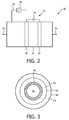
Fig. 2 shows a schematic cross sectional view of a plasma pump according to the invention. -
Fig. 3 shows a schematic cross sectional view of a membrane unit according to the invention. - In
Fig. 1 , anarrangement 10 for separating oxygen from an oxygen containing gas is schematically shown. Thearrangement 10 is very well suitable for oxygen therapy e.g. in home care applications. However, thearrangement 10 as well as the method according to the invention is not limited to therapeutic applications, but is furthermore suitable for a all kinds of generation of oxygen. As a further exemplary application, it is referred to the oxygen generation in airplanes. - The
arrangement 10 comprises agas inlet 12 for guiding the oxygen containing gas into thearrangement 10. The oxygen containing gas is guided through thegas inlet 12 into aplasma pump 16, and in the following it is entering, through aconduct 18, amembrane unit 22 for separating oxygen. Downstream themembrane unit 22, aconduct 24 may guide the generated pure oxygen to a cooler 26 downstream of which anoutlet 28 is provided for administration of the oxygen. Thearrangement 10 is described in more detail below. - The
gas inlet 12 guides the oxygen containing gas into a power-modulated gas discharge compression unit, i.e. aplasma pump 16. Anexemplary plasma pump 16, which is well suitable for a method according to the invention, is shown in more detail inFig. 2 . - The
plasma pump 16 may comprise adischarge chamber 30 with agas discharge device 32 for generating a gas discharge inside thedischarge chamber 30. Thegas discharge device 32 may comprise a coupling device to generate a gas discharge by capacitive, inductive, surface wave and/or microwave coupling, and anenergy source 34 to provide the coupling device with an alternating current. The coupling device may comprise twoelectrodes gas discharge chamber 30 for capacitive coupling and which may be formed of carbon. It is preferred, that the coupling device is arranged outside thegas discharge chamber 30. The wearing down of parts of the coupling device, especially ofelectrodes energy source 34, a voltage could be applied between the twoelectrodes discharge chamber 30. An alternating current allows to sustain the plasma over time, by changing of the amplitude of the alternating current the power of the plasma can be modulated. - The
discharge chamber 30 further comprises agas inlet 40, afirst gas outlet 42 and asecond gas outlet 44. Thegas inlet 40 of theplasma pump 16 is connected to thegas inlet 12 of thearrangement 10. Thefirst gas outlet 42 may further comprise anexhaust device 46 which may be designed as a simple two way valve. It is on one side connected to thedischarge chamber 30 and on the other side connected to the atmosphere or a reservoir for exhaust gas. - The
discharge chamber 30 is further connected to thesecond gas outlet 44 which in turn is connected to theconduct 18. To control gas flow through thegas inlet 40 and thesecond gas outlet 44, aninlet valve 48 is connected with thegas inlet 40 and anoutlet valve 50 is connected with the second gas outlet 44 (seefig. 1 ). Asinlet valve 48 andoutlet valve 50, non-return valves or two-way valves can be used, for example. Non-return valves are preferred because they do not need controlling. By adapting the operation of theinlet valve 48 and theoutlet valve 50 to a power modulated gas discharge, a gas flow can be generated with a specific direction. - By generating a plasma in the
discharge chamber 30 like described above, a pressurized oxygen containing gas is generated. A pressure in thedischarge chamber 30 can be increased during high power-operation of the plasma, and the pressure can be decreased during low power operation or turning off the plasma. A pressure swing can be obtained by running a power-modulated discharge in thedischarge chamber 30. - In the following, the operation of the
plasma pump 16 will be described in more detail in an exemplary manner. - In a first step, it is started at approximately atmospheric pressure, for example 1 bar, and at approximately room temperature, for example 300 K, with
closed exhaust device 46,inlet valve 48 andoutlet valve 50. A high-power plasma inside the discharge chamber is generated and sustained leading to an increased temperature. Due to the fact that the discharge chamber is closed against the surrounding air, the oxygen containing gas in the discharge chamber of theplasma pump 16 is compressed. Exemplarily, the pressure may thus be increased up to a value of 3 bars due to an increasing temperature of the gas up to a temperature of 900 K caused by the plasma. By opening theoutlet valve 50, the oxygen containing gas in thedischarge chamber 30 can only leave thechamber 30 by flowing in theconduct 18, thereby causing a constant pressure at further elevated temperatures up to a range of 2100 K in thedischarge chamber 30. After a certain interval, in a third step, thegas exhaust device 46 may be opened to the surrounding air. During this phase, the pressure in thedischarge chamber 30 goes down to atmospheric pressure and the temperature is increased to a temperature of approximately 1550 K. After a certain interval, the discharge power is reduced significantly or is switched of leading to the gas temperature dropping to approximately room temperature, e.g. 300 K. Fresh oxygen containing gas may now flow into thedischarge chamber 30 through thegas inlet 12 and theinlet 40. - After a further time interval, the cycle is finished. For continuing, the
plasma pump 16 starts again with the first step. If the plasma has not been switched off, igniting the plasma in the following step can be omitted. - The
plasma pump 16 can be operated without an overlapping of the respective steps. Alternatively, theplasma pump 16 can be operated with one or more steps overlapping. - The gas temperatures during burning the plasma may be very high, like described above. Even though there is a temperature distribution leading to the walls of the
plasma pump 16 having temperatures being decreased with respect to the central axis, the use of temperature stable materials like quartz glass or aluminum oxides as wall materials of the plasma pump are advantageous. - Generally, a rather small energy input for the
plasma pump 16 is sufficient. In detail, a power input of 100W to 350W may be sufficient depending on the temperature and membrane conditions. This range of power input is very well suitable for home care applications. - The
energy source 34 may deliver a square wave current I at 300 Hz frequency with variable output power, i.e. the root mean square (rms) value of the current Imean at 300 Hz driving frequency can be varied on a time scale above t=50 ms. Currents Imean up to several amperes and powers of several hundred watts are feasible with the electronic driver. Theenergy source 10 also delivers peak voltages of up to 20 kV for start phase to obtain a gas breakdown / igniting the plasma. - Working in the described cycle, the
plasma pump 16 functions as a gas pump. Although theplasma pump 16 woks in different cycles, it may generate a direct and continuous flow of oxygen containing gas due to a high frequency of the working cycles. - To further support a continuous flow, it is preferable to provide a
gas reservoir 52 downstream theoutlet valve 50. By pressing oxygen containing gas from thedischarge chamber 30 inside thegas reservoir 52, an over pressure inside thereservoir 52 can be generated, preferably by increasing the flow resistance downstream the gas reservoir by providing areservoir valve 54 or, alternatively, an orifice. A constant or nearly constant over pressure can be used to generate a continuous or nearly continuous flow of the oxygen containing gas in theconduct 18. - Downstream the
plasma pump 16 or thereservoir 52, respectively, the oxygen containing gas is guided to themembrane unit 22. Upstream themembrane unit 22, a a valve may be provided, which may be thereservoir valve 54 or an additional valve. This valve may close theconduct 18, when the pressure of the oxygen containing gas is insufficient. Contrary thereto, the valve may open theconduct 18 when a sufficiently high pressure is reached. Thus, it may be provided that at a pressure of ≥ 2.5 bars, in particular at 5 bars, the valve opens, and thus guiding the oxygen containing gas to themembrane unit 22. -
Fig. 3 shows a cross sectional view of themembrane unit 22. Themembrane unit 22 may be of any configuration. However, a tubular shape of themembrane unit 22 is especially advantageous. At its inside, themembrane unit 22 comprises aninner conduct 56 being in flow connection with theconduct 18, and allowing the oxygen containing gas to enter themembrane unit 22. Theinner conduct 56 is limited at its outside by aninorganic membrane 58, theinorganic membrane 58 having a primary and a secondary side. The primary side is directed to theinner conduct 56 and thus to theplasma pump 16, whereas the secondary side is directed to anouter conduct 60. Theouter conduct 60 is limited at its inner side by theinorganic membrane 58 and at its outer side by aninner housing 62. Theinner housing 62 may be a tube made from a material being resistant against higher temperatures, for example quartz glass or ceramic aluminum oxide. The objective of theouter conduct 60 is to conduct the separated oxygen out of themembrane unit 22 and is thus in flow connection with theconduct 24. Outside theinner housing 60, aheat isolation 64 is provided. This may preferably be a vacuum, which is provided between theinner housing 62 and anouter housing 66. It is as well possible to provide an inert gas between theinner housing 62 and theouter housing 66. In this case, it would be preferable to provide a very short distance between theinner housing 62 and theouter housing 66 to achieve a sufficient isolation.
However, theisolation 64 may be of any kind known from the state of the art to get a sufficient isolation effect. Theouter housing 66 may be designed as a thermal shield, for example based on aluminum, to further improve the isolation. This in fact improves the energy efficiency of thearrangement 10 and is thus cost saving. - Referring back to the
inorganic membrane 58, its objective is to separate the oxygen from the remaining retentate flow, i.e. the remaining constituents of the oxygen containing gas, and thus to provide a flow of oxygen, which advantageously is a flow of 100% pure oxygen. Mostly, the main remaining constituent is nitrogen, especially in the case when air is used as oxygen containing gas. To get sufficient separation results, it is thus essential that theinorganic membrane 58 is very dense. A denseinorganic membrane 58 is a membrane being is permeable with respect to oxygen, but being strictly or at least substantially non-permeable for other gases, especially for nitrogen. - To achieve these properties, the
inorganic membrane 58 may be a solid ceramic membrane comprising selected inorganic oxide compounds. Preferable inorganic membranes are mainly based on a Perovskite or Fluorite crystal structure. As an example, the Perovskite-related material Ba0.5Sr0.5Co0.5Fe0.2O3-δ (BSCF) is very well suited. It is a general property of these kinds of inorganic membranes that they are completely impervious to all gases at room temperature, but allow oxygen molecules to pass through when heated to elevated temperatures. Mainly, temperatures above 700 K are necessary to achieve a good oxygen flow with the requirement of only small sized membranes. For example, the above named BSCF may come up with an oxygen flow of 13ml/cm2min at 1275K, wherein a membrane thickness of only 0.2 mm is sufficient. - The inorganic membranes may be either pure oxygen conducting membranes or mixed ionic-electronic conducting membranes. Generally, a force has to be applied to cause the oxygen being transferred through the membrane. This may either be an electronic force. However, it is preferred, that the oxygen passes the
inorganic membrane 58 due to a pressure difference between the primary and the secondary side of theinorganic membrane 58. - The compression of the oxygen containing gas in the
plasma pump 16 at the same time leads to a pressure difference between the primary side and the secondary side of theinorganic membrane 58. Due to this effect, an increased oxygen partial-pressure at the primary side is generated enabling an oxygen flow through, or a transfer across the denseinorganic membrane 58, respectively. This flow may further be enhanced by providing a reduced pressure on the secondary side of theinorganic membrane 58 instead of an increased pressure at the primary side of theinorganic membrane 58 or additionally thereto. Under extreme conditions, a vacuum may be provided on the secondary side of theinorganic membrane 58 to provide a sufficiently high oxygen flow through themembrane 58. - Without using a reduced pressure on the secondary side, it is preferable to use pressures of ≥ 2.5 bars upstream the
inorganic membrane 58, thus on its primary side. Here, it is especially preferable to use pressures lying in the range of 5 or ≤ 5 bars. Depending from the temperature of theinorganic membrane 58 and the dimensions of the latter, an oxygen flow with a modest elevation compared to atmospheric pressure, approximately 1 bar, may be achieved at theoutlet 28. This may achieved with a pressure of the oxygen containing gas being sensibly reduced with respect to the state of the art. The pressure range according to the invention is especially suitable for home care applications. - It is apparent, that the
inorganic membrane 58 has to be stable enough to stand these conditions like described above. This is especially important, as it is preferred to form theinorganic membrane 58 in a very small size or thickness. Especially, by providing an extensive pressure gradient between the primary side and the secondary side of theinorganic membrane 58, it may be advantageous to fix theinorganic membrane 58 on a support. The support may be formed as a porous membrane, in particular a thick inorganic membrane like used for coarse filters. A porous membrane as referred to in this case is a membrane being permeable for gases and non-selective with respect to oxygen. This enables an enhanced stability of theinorganic membrane 58 without the requirement of forming theinorganic membrane 58 as such more stable. This further reduces costs, as the stable and forming component is the membrane support, which is much cheaper than theinorganic membrane 58. - Like stated above, it is essential to heat the
inorganic membrane 58 to get sufficient oxygen permeability. According to the invention, this is achieved in an easy and simple way. Due to the provision of aplasma pump 16 for compressing the oxygen containing gas, the compressed gas at the same time is heated to a temperature range being sufficiently high to heat theinorganic membrane 58 to its operational temperature. Exemplary temperature ranges are temperatures ≥ 700K. It is especially preferable to heat the oxygen containing gas and thus the inorganic membrane to ranges of ≥ 900K to ≤ 1300K. In these temperature ranges, very suitable oxygen flows may be achieved. - The combination of a
plasma pump 16 to compress and heat the oxygen containing gas together with aninorganic membrane 58 to separate the oxygen from the remaining retentate flow thus improves the energy efficiency of thearrangement 10. It is not necessary to provide a further means for heating the oxygen containing gas and thus the inorganic membrane. This makes anarrangement 10 according to the invention cost-reducing and furthermore enhances size and weight properties, which is especially advantageous for home care applications. Furthermore, the arrangement is kind of "self-cleaning" as due to the high temperatures generated in theplasma pump 16, the oxygen containing gas is sterilized. This has the further advantage of the generated oxygen being sterile, which is preferable for a great amount of applications. - Referring back to
Fig. 1 , themembrane unit 22 furthermore comprises anoutlet 68 which is connected on the one side to theinner conduct 56 and on the other side may be connected to the atmosphere. Through theoutlet 68, gas with reduced oxygen content, especially nitrogen, leaves themembrane unit 22. This is the exhaust gas of themembrane unit 22. Theoutlet 68 may comprise afurther valve 70, which is especially advantageous, if a pressure is provided inside theinner conduct 56. - Downstream the
membrane unit 22, theconduct 24, which may comprise a further valve like a non return valve, is connected to anoutlet 28. Theoutlet 28 may be equipped withmouthpiece 72 or the like, enabling a direct administration of the generated oxygen. Thus, an additional valve or a small compressor may be provided for a sufficient flow of pure oxygen. Downstream theconduct 24, but upstream theoutlet 28, a cooler 26 may optionally be provided. The cooling of cooler 26 may be done by a forced air stream using the surrounding air -(using a ventilator or the like). It may be necessary as the oxygen is still in elevated temperatures downstream theinorganic membrane 58 and it is advantageous for a great amount of applications to cool down the generated oxygen, in an exemplary case, to room temperature. However, it might be advantageous, not to cool down the oxygen, because some oxygen based therapies are more efficient by using oxygen with elevated temperatures. - While the invention has been illustrated and described in detail in the drawings and foregoing description, such illustration and description are to be considered illustrative or exemplary and not restrictive; the invention is not limited to the disclosed embodiments.
- The invention is defined in the appended claims. In the claims, the word "comprising" does not exclude other elements or steps, and the indefinite article "a" or "an" does not exclude a plurality. The mere fact that certain measures are recited in mutually different dependent claims does not indicate that a combination of these measures cannot be used to advantage. Any reference signs in the claims should not be construed as limiting the scope.
Claims (12)
- Method of separating oxygen from an oxygen containing gas, said method comprising the steps of:guiding heated and compressed oxygen containing gas to the primary side of a dense inorganic membrane (58), therebyheating the inorganic membrane (58) by the oxygen containing gas to a temperature at which it is permeable for oxygen, andcreating a pressure difference between the primary side and a secondary side of the inorganic membrane (58), whereinan oxygen flow through the inorganic membrane (58) is created, thereby separating the oxygen from the oxygen containing gas,characterized in thatthe heated and compressed oxygen is generated by compressing and heating the oxygen containing gas in a plasma pump (16).
- Method according to claim 1, wherein air is used as oxygen containing gas.
- Method according to claim 1 or 2, wherein the oxygen containing gas is compressed to a range of ≥ 2.5 bars, in particular to a range of 5 bars to directly come up with an oxygen pressure above atmospheric pressure on the secondary side.
- Method according to any of claims 1 to 3, wherein the oxygen containing gas is heated to a temperature range of ≥ 900 K and ≤ 1300 K.
- Method according to any of claims 1 to 3, wherein the oxygen is cooled after separation.
- Oxygen separating arrangement (10), comprising:a membrane unit (22) with a dense inorganic membrane (58), the dense inorganic membrane being designed to separate oxygen from an oxygen containing gas characterized in that the oxygen separation arrangement further comprises:a plasma pump (16) for compressing and heating the oxygen containing gas, wherein the plasma pump (16) and the membrane unit (22) are connected via a conduct (18) being designed to guide the heated and compressed oxygen containing gas from the plasma pump (16) to the membrane unit (22).
- Arrangement (10) according to claim 6, wherein the inorganic membrane (58) is formed in a tubular shape.
- Arrangement (10) according to claim 6 or 7, wherein the arrangement (10) comprises a cooler (26) being arranged downstream the membrane unit (22)
- Arrangement (10) according to any of claims 6 to 8, wherein a gas reservoir (52) is provided downstream the plasma pump (16).
- Arrangement (10) according to any of claims 6 to 9, wherein the inorganic membrane (58) is fixed to a support formed as a porous membrane.
- Arrangement (10) according to any of claims 6 to 10, wherein a heat isolation (64) is provided outside the inner housing (48).
- Arrangement (10) according to claim 11, wherein the heat isolation (64) is designed as a vacuum.
Priority Applications (1)
| Application Number | Priority Date | Filing Date | Title |
|---|---|---|---|
| EP10809076.2A EP2512635B1 (en) | 2009-12-17 | 2010-12-14 | Oxygen separation method and system with a plasma pump and a membrane |
Applications Claiming Priority (3)
| Application Number | Priority Date | Filing Date | Title |
|---|---|---|---|
| EP09179682 | 2009-12-17 | ||
| EP10809076.2A EP2512635B1 (en) | 2009-12-17 | 2010-12-14 | Oxygen separation method and system with a plasma pump and a membrane |
| PCT/IB2010/055787 WO2011073889A1 (en) | 2009-12-17 | 2010-12-14 | Oxygen separation method and system with a plasma pump and a membrane |
Publications (2)
| Publication Number | Publication Date |
|---|---|
| EP2512635A1 EP2512635A1 (en) | 2012-10-24 |
| EP2512635B1 true EP2512635B1 (en) | 2016-03-16 |
Family
ID=43837903
Family Applications (1)
| Application Number | Title | Priority Date | Filing Date |
|---|---|---|---|
| EP10809076.2A Active EP2512635B1 (en) | 2009-12-17 | 2010-12-14 | Oxygen separation method and system with a plasma pump and a membrane |
Country Status (5)
| Country | Link |
|---|---|
| US (1) | US8696795B2 (en) |
| EP (1) | EP2512635B1 (en) |
| JP (1) | JP6096513B2 (en) |
| CN (1) | CN102753251B (en) |
| WO (1) | WO2011073889A1 (en) |
Families Citing this family (12)
| Publication number | Priority date | Publication date | Assignee | Title |
|---|---|---|---|---|
| KR101805873B1 (en) | 2011-08-03 | 2018-01-10 | 한화케미칼 주식회사 | A nanoparticles of surface-modified with monosaccharide phosphate or monosaccharide phosphate derivatives, its colloidal solution and use thereof |
| US9861712B2 (en) | 2010-08-05 | 2018-01-09 | Hanwha Chemical Corporation | Preparation of extremely small and uniform sized, iron oxide-based paramagnetic or pseudo-paramagnetic nanoparticles and MRI T1 contrast agents using the same |
| CN103124689B (en) * | 2010-09-22 | 2016-03-16 | 皇家飞利浦电子股份有限公司 | Produce oxygen and nitric oxide production method and apparatus |
| WO2012147015A1 (en) * | 2011-04-28 | 2012-11-01 | Koninklijke Philips Electronics N.V. | Method and arrangement for generating oxygen |
| US20150097485A1 (en) * | 2013-10-08 | 2015-04-09 | XEI Scientific Inc. | Method and apparatus for plasma ignition in high vacuum chambers |
| DE102014115849A1 (en) * | 2014-10-30 | 2016-05-04 | Fraunhofer-Gesellschaft zur Förderung der angewandten Forschung e.V. | Method and arrangement for generating and thermally compressing oxygen |
| US11247015B2 (en) | 2015-03-24 | 2022-02-15 | Ventec Life Systems, Inc. | Ventilator with integrated oxygen production |
| US10315002B2 (en) | 2015-03-24 | 2019-06-11 | Ventec Life Systems, Inc. | Ventilator with integrated oxygen production |
| US10773049B2 (en) | 2016-06-21 | 2020-09-15 | Ventec Life Systems, Inc. | Cough-assist systems with humidifier bypass |
| EP3781244A4 (en) | 2018-05-13 | 2022-01-19 | Ventec Life Systems, Inc. | Portable medical ventilator system using portable oxygen concentrators |
| FR3093926B1 (en) * | 2019-03-22 | 2022-10-28 | Air Liquide | Apparatus and installation for supplying a gas mixture to a patient |
| CN112999985B (en) * | 2019-12-20 | 2023-08-25 | 南京工业大学 | Method for strengthening oxygen permeation process of mixed conductor film by using plasma |
Family Cites Families (23)
| Publication number | Priority date | Publication date | Assignee | Title |
|---|---|---|---|---|
| SE434676B (en) * | 1981-10-22 | 1984-08-06 | Skf Steel Eng Ab | SET AND DEVICE FOR HEATING OF INDUSTRIAL ENDAL PROCESS AIR |
| US4560394A (en) * | 1981-12-18 | 1985-12-24 | The Garrett Corporation | Oxygen enrichment system |
| DE3568006D1 (en) * | 1984-05-24 | 1989-03-09 | Terumo Corp | Hollow fiber membrane type oxygenator and method for manufacturing same |
| US4625092A (en) * | 1984-11-30 | 1986-11-25 | Plasma Energy Corporation | Plasma arc bulk air heating apparatus |
| US4834779A (en) * | 1986-10-27 | 1989-05-30 | Liquid Air Corporation | Process for membrane seperation of gas mixtures |
| US5355764A (en) * | 1992-05-04 | 1994-10-18 | Fmc Corporation | Plasma actuated ignition and distribution pump |
| DE69619299T2 (en) * | 1995-06-07 | 2002-10-10 | Air Prod & Chem | Oxygen production with ion transport membranes and energy recovery |
| US7431909B1 (en) * | 1998-12-04 | 2008-10-07 | Cabot Corporation | Process for production of carbon black |
| US20020100836A1 (en) * | 2001-01-31 | 2002-08-01 | Hunt Robert Daniel | Hydrogen and oxygen battery, or hudrogen and oxygen to fire a combustion engine and/or for commerce. |
| JP3891834B2 (en) * | 2001-12-04 | 2007-03-14 | 大陽日酸株式会社 | Gas supply method and apparatus |
| CA2487850C (en) * | 2002-05-31 | 2008-12-16 | Nozomu Tanihara | Fuel cell-use humidifier |
| US6667475B1 (en) * | 2003-01-08 | 2003-12-23 | Applied Materials, Inc. | Method and apparatus for cleaning an analytical instrument while operating the analytical instrument |
| GB2397303B (en) * | 2003-01-17 | 2007-04-04 | Smartmembrane Corp | Gas separation membranes |
| US7088106B2 (en) | 2003-06-27 | 2006-08-08 | University Of Wyoming | Device and method for the measurement of gas permeability through membranes |
| US7384619B2 (en) | 2003-06-30 | 2008-06-10 | Bar-Gadda, Llc | Method for generating hydrogen from water or steam in a plasma |
| US7694674B2 (en) | 2004-09-21 | 2010-04-13 | Carleton Life Support Systems, Inc. | Oxygen generator with storage and conservation modes |
| US7763097B2 (en) * | 2006-06-08 | 2010-07-27 | University of Pittsburgh—of the Commonwealth System of Higher Education | Devices, systems and methods for reducing the concentration of a chemical entity in fluids |
| JP2013506544A (en) * | 2009-09-30 | 2013-02-28 | コーニンクレッカ フィリップス エレクトロニクス エヌ ヴィ | Gas concentrator |
| US8821828B2 (en) * | 2009-12-23 | 2014-09-02 | Koninklijke Philips N.V. | Method for generating nitric oxide |
| CN102740958A (en) * | 2010-02-03 | 2012-10-17 | 皇家飞利浦电子股份有限公司 | Membrane for oxygen generation |
| EP2542329A1 (en) * | 2010-03-05 | 2013-01-09 | Koninklijke Philips Electronics N.V. | Oxygen separation membrane |
| CN103124689B (en) * | 2010-09-22 | 2016-03-16 | 皇家飞利浦电子股份有限公司 | Produce oxygen and nitric oxide production method and apparatus |
| BR112013009352B1 (en) * | 2010-10-22 | 2020-07-28 | Koninklijke Philips N. V | OXYGEN SEPARATION PROVISION OF OXYGEN CONTAINING GAS AND OXYGEN SEPARATION METHOD OF OXYGEN CONTAINING OXYGEN |
-
2010
- 2010-12-14 JP JP2012543966A patent/JP6096513B2/en active Active
- 2010-12-14 WO PCT/IB2010/055787 patent/WO2011073889A1/en active Application Filing
- 2010-12-14 US US13/515,525 patent/US8696795B2/en active Active
- 2010-12-14 EP EP10809076.2A patent/EP2512635B1/en active Active
- 2010-12-14 CN CN201080056788.8A patent/CN102753251B/en active Active
Also Published As
| Publication number | Publication date |
|---|---|
| WO2011073889A1 (en) | 2011-06-23 |
| CN102753251B (en) | 2016-11-16 |
| EP2512635A1 (en) | 2012-10-24 |
| CN102753251A (en) | 2012-10-24 |
| JP2013514123A (en) | 2013-04-25 |
| JP6096513B2 (en) | 2017-03-15 |
| US8696795B2 (en) | 2014-04-15 |
| US20120247329A1 (en) | 2012-10-04 |
Similar Documents
| Publication | Publication Date | Title |
|---|---|---|
| EP2512635B1 (en) | Oxygen separation method and system with a plasma pump and a membrane | |
| JP2013514123A5 (en) | ||
| US8906137B2 (en) | Arrangement and method for separating oxygen | |
| JP5848780B2 (en) | Method and configuration for generating oxygen | |
| WO2011052803A1 (en) | Oxygen enrichment device | |
| US8999039B2 (en) | Oxygen separation membrane | |
| EP2065067A1 (en) | Oxygen concentrator | |
| JP2013056810A (en) | Method and apparatus for concentrating ozone gas | |
| US8920539B2 (en) | Method and arrangement for generating oxygen and nitric oxide | |
| AU2010302301B2 (en) | Gas concentration arrangement | |
| US20170101314A1 (en) | Method and arrangement for generating oxygen | |
| JP5431662B2 (en) | Oxygen concentrator | |
| JP5193537B2 (en) | Oxygen concentrator | |
| JPH06105873A (en) | Oxygen tent | |
| CN116119621A (en) | Hydrogen-oxygen mixed gas preparation device with adjustable hydrogen content and method thereof | |
| JP2009089777A (en) | Oxygen concentrator |
Legal Events
| Date | Code | Title | Description |
|---|---|---|---|
| PUAI | Public reference made under article 153(3) epc to a published international application that has entered the european phase |
Free format text: ORIGINAL CODE: 0009012 |
|
| 17P | Request for examination filed |
Effective date: 20120717 |
|
| AK | Designated contracting states |
Kind code of ref document: A1 Designated state(s): AL AT BE BG CH CY CZ DE DK EE ES FI FR GB GR HR HU IE IS IT LI LT LU LV MC MK MT NL NO PL PT RO RS SE SI SK SM TR |
|
| DAX | Request for extension of the european patent (deleted) | ||
| RAP1 | Party data changed (applicant data changed or rights of an application transferred) |
Owner name: PHILIPS INTELLECTUAL PROPERTY & STANDARDS GMBH Owner name: KONINKLIJKE PHILIPS N.V. |
|
| 17Q | First examination report despatched |
Effective date: 20140904 |
|
| GRAP | Despatch of communication of intention to grant a patent |
Free format text: ORIGINAL CODE: EPIDOSNIGR1 |
|
| INTG | Intention to grant announced |
Effective date: 20150721 |
|
| GRAS | Grant fee paid |
Free format text: ORIGINAL CODE: EPIDOSNIGR3 |
|
| GRAA | (expected) grant |
Free format text: ORIGINAL CODE: 0009210 |
|
| AK | Designated contracting states |
Kind code of ref document: B1 Designated state(s): AL AT BE BG CH CY CZ DE DK EE ES FI FR GB GR HR HU IE IS IT LI LT LU LV MC MK MT NL NO PL PT RO RS SE SI SK SM TR |
|
| REG | Reference to a national code |
Ref country code: GB Ref legal event code: FG4D |
|
| REG | Reference to a national code |
Ref country code: CH Ref legal event code: EP |
|
| REG | Reference to a national code |
Ref country code: IE Ref legal event code: FG4D |
|
| REG | Reference to a national code |
Ref country code: AT Ref legal event code: REF Ref document number: 780703 Country of ref document: AT Kind code of ref document: T Effective date: 20160415 |
|
| REG | Reference to a national code |
Ref country code: DE Ref legal event code: R096 Ref document number: 602010031288 Country of ref document: DE |
|
| REG | Reference to a national code |
Ref country code: NL Ref legal event code: MP Effective date: 20160316 |
|
| REG | Reference to a national code |
Ref country code: LT Ref legal event code: MG4D |
|
| PG25 | Lapsed in a contracting state [announced via postgrant information from national office to epo] |
Ref country code: FI Free format text: LAPSE BECAUSE OF FAILURE TO SUBMIT A TRANSLATION OF THE DESCRIPTION OR TO PAY THE FEE WITHIN THE PRESCRIBED TIME-LIMIT Effective date: 20160316 Ref country code: NO Free format text: LAPSE BECAUSE OF FAILURE TO SUBMIT A TRANSLATION OF THE DESCRIPTION OR TO PAY THE FEE WITHIN THE PRESCRIBED TIME-LIMIT Effective date: 20160616 Ref country code: GR Free format text: LAPSE BECAUSE OF FAILURE TO SUBMIT A TRANSLATION OF THE DESCRIPTION OR TO PAY THE FEE WITHIN THE PRESCRIBED TIME-LIMIT Effective date: 20160617 Ref country code: HR Free format text: LAPSE BECAUSE OF FAILURE TO SUBMIT A TRANSLATION OF THE DESCRIPTION OR TO PAY THE FEE WITHIN THE PRESCRIBED TIME-LIMIT Effective date: 20160316 |
|
| REG | Reference to a national code |
Ref country code: AT Ref legal event code: MK05 Ref document number: 780703 Country of ref document: AT Kind code of ref document: T Effective date: 20160316 |
|
| PG25 | Lapsed in a contracting state [announced via postgrant information from national office to epo] |
Ref country code: LT Free format text: LAPSE BECAUSE OF FAILURE TO SUBMIT A TRANSLATION OF THE DESCRIPTION OR TO PAY THE FEE WITHIN THE PRESCRIBED TIME-LIMIT Effective date: 20160316 Ref country code: RS Free format text: LAPSE BECAUSE OF FAILURE TO SUBMIT A TRANSLATION OF THE DESCRIPTION OR TO PAY THE FEE WITHIN THE PRESCRIBED TIME-LIMIT Effective date: 20160316 Ref country code: SE Free format text: LAPSE BECAUSE OF FAILURE TO SUBMIT A TRANSLATION OF THE DESCRIPTION OR TO PAY THE FEE WITHIN THE PRESCRIBED TIME-LIMIT Effective date: 20160316 Ref country code: NL Free format text: LAPSE BECAUSE OF FAILURE TO SUBMIT A TRANSLATION OF THE DESCRIPTION OR TO PAY THE FEE WITHIN THE PRESCRIBED TIME-LIMIT Effective date: 20160316 Ref country code: LV Free format text: LAPSE BECAUSE OF FAILURE TO SUBMIT A TRANSLATION OF THE DESCRIPTION OR TO PAY THE FEE WITHIN THE PRESCRIBED TIME-LIMIT Effective date: 20160316 |
|
| PG25 | Lapsed in a contracting state [announced via postgrant information from national office to epo] |
Ref country code: PL Free format text: LAPSE BECAUSE OF FAILURE TO SUBMIT A TRANSLATION OF THE DESCRIPTION OR TO PAY THE FEE WITHIN THE PRESCRIBED TIME-LIMIT Effective date: 20160316 Ref country code: IS Free format text: LAPSE BECAUSE OF FAILURE TO SUBMIT A TRANSLATION OF THE DESCRIPTION OR TO PAY THE FEE WITHIN THE PRESCRIBED TIME-LIMIT Effective date: 20160716 Ref country code: EE Free format text: LAPSE BECAUSE OF FAILURE TO SUBMIT A TRANSLATION OF THE DESCRIPTION OR TO PAY THE FEE WITHIN THE PRESCRIBED TIME-LIMIT Effective date: 20160316 |
|
| PG25 | Lapsed in a contracting state [announced via postgrant information from national office to epo] |
Ref country code: RO Free format text: LAPSE BECAUSE OF FAILURE TO SUBMIT A TRANSLATION OF THE DESCRIPTION OR TO PAY THE FEE WITHIN THE PRESCRIBED TIME-LIMIT Effective date: 20160316 Ref country code: AT Free format text: LAPSE BECAUSE OF FAILURE TO SUBMIT A TRANSLATION OF THE DESCRIPTION OR TO PAY THE FEE WITHIN THE PRESCRIBED TIME-LIMIT Effective date: 20160316 Ref country code: ES Free format text: LAPSE BECAUSE OF FAILURE TO SUBMIT A TRANSLATION OF THE DESCRIPTION OR TO PAY THE FEE WITHIN THE PRESCRIBED TIME-LIMIT Effective date: 20160316 Ref country code: PT Free format text: LAPSE BECAUSE OF FAILURE TO SUBMIT A TRANSLATION OF THE DESCRIPTION OR TO PAY THE FEE WITHIN THE PRESCRIBED TIME-LIMIT Effective date: 20160718 Ref country code: CZ Free format text: LAPSE BECAUSE OF FAILURE TO SUBMIT A TRANSLATION OF THE DESCRIPTION OR TO PAY THE FEE WITHIN THE PRESCRIBED TIME-LIMIT Effective date: 20160316 Ref country code: SK Free format text: LAPSE BECAUSE OF FAILURE TO SUBMIT A TRANSLATION OF THE DESCRIPTION OR TO PAY THE FEE WITHIN THE PRESCRIBED TIME-LIMIT Effective date: 20160316 Ref country code: SM Free format text: LAPSE BECAUSE OF FAILURE TO SUBMIT A TRANSLATION OF THE DESCRIPTION OR TO PAY THE FEE WITHIN THE PRESCRIBED TIME-LIMIT Effective date: 20160316 |
|
| REG | Reference to a national code |
Ref country code: DE Ref legal event code: R097 Ref document number: 602010031288 Country of ref document: DE |
|
| REG | Reference to a national code |
Ref country code: FR Ref legal event code: PLFP Year of fee payment: 7 |
|
| PG25 | Lapsed in a contracting state [announced via postgrant information from national office to epo] |
Ref country code: BE Free format text: LAPSE BECAUSE OF FAILURE TO SUBMIT A TRANSLATION OF THE DESCRIPTION OR TO PAY THE FEE WITHIN THE PRESCRIBED TIME-LIMIT Effective date: 20160316 Ref country code: IT Free format text: LAPSE BECAUSE OF FAILURE TO SUBMIT A TRANSLATION OF THE DESCRIPTION OR TO PAY THE FEE WITHIN THE PRESCRIBED TIME-LIMIT Effective date: 20160316 |
|
| PLBE | No opposition filed within time limit |
Free format text: ORIGINAL CODE: 0009261 |
|
| STAA | Information on the status of an ep patent application or granted ep patent |
Free format text: STATUS: NO OPPOSITION FILED WITHIN TIME LIMIT |
|
| PG25 | Lapsed in a contracting state [announced via postgrant information from national office to epo] |
Ref country code: DK Free format text: LAPSE BECAUSE OF FAILURE TO SUBMIT A TRANSLATION OF THE DESCRIPTION OR TO PAY THE FEE WITHIN THE PRESCRIBED TIME-LIMIT Effective date: 20160316 |
|
| 26N | No opposition filed |
Effective date: 20161219 |
|
| PG25 | Lapsed in a contracting state [announced via postgrant information from national office to epo] |
Ref country code: BG Free format text: LAPSE BECAUSE OF FAILURE TO SUBMIT A TRANSLATION OF THE DESCRIPTION OR TO PAY THE FEE WITHIN THE PRESCRIBED TIME-LIMIT Effective date: 20160616 |
|
| PG25 | Lapsed in a contracting state [announced via postgrant information from national office to epo] |
Ref country code: SI Free format text: LAPSE BECAUSE OF FAILURE TO SUBMIT A TRANSLATION OF THE DESCRIPTION OR TO PAY THE FEE WITHIN THE PRESCRIBED TIME-LIMIT Effective date: 20160316 |
|
| REG | Reference to a national code |
Ref country code: CH Ref legal event code: PL |
|
| GBPC | Gb: european patent ceased through non-payment of renewal fee |
Effective date: 20161214 |
|
| PG25 | Lapsed in a contracting state [announced via postgrant information from national office to epo] |
Ref country code: MC Free format text: LAPSE BECAUSE OF FAILURE TO SUBMIT A TRANSLATION OF THE DESCRIPTION OR TO PAY THE FEE WITHIN THE PRESCRIBED TIME-LIMIT Effective date: 20160316 |
|
| REG | Reference to a national code |
Ref country code: IE Ref legal event code: MM4A |
|
| PG25 | Lapsed in a contracting state [announced via postgrant information from national office to epo] |
Ref country code: LU Free format text: LAPSE BECAUSE OF NON-PAYMENT OF DUE FEES Effective date: 20161214 Ref country code: CH Free format text: LAPSE BECAUSE OF NON-PAYMENT OF DUE FEES Effective date: 20161231 Ref country code: LI Free format text: LAPSE BECAUSE OF NON-PAYMENT OF DUE FEES Effective date: 20161231 |
|
| PG25 | Lapsed in a contracting state [announced via postgrant information from national office to epo] |
Ref country code: IE Free format text: LAPSE BECAUSE OF NON-PAYMENT OF DUE FEES Effective date: 20161214 Ref country code: GB Free format text: LAPSE BECAUSE OF NON-PAYMENT OF DUE FEES Effective date: 20161214 |
|
| REG | Reference to a national code |
Ref country code: FR Ref legal event code: PLFP Year of fee payment: 8 |
|
| REG | Reference to a national code |
Ref country code: DE Ref legal event code: R082 Ref document number: 602010031288 Country of ref document: DE Representative=s name: MEISSNER BOLTE PATENTANWAELTE RECHTSANWAELTE P, DE Ref country code: DE Ref legal event code: R081 Ref document number: 602010031288 Country of ref document: DE Owner name: PHILIPS GMBH, DE Free format text: FORMER OWNER: PHILIPS INTELLECTUAL PROPERTY & STANDARDS GMBH, 20099 HAMBURG, DE |
|
| PG25 | Lapsed in a contracting state [announced via postgrant information from national office to epo] |
Ref country code: CY Free format text: LAPSE BECAUSE OF FAILURE TO SUBMIT A TRANSLATION OF THE DESCRIPTION OR TO PAY THE FEE WITHIN THE PRESCRIBED TIME-LIMIT Effective date: 20160316 Ref country code: HU Free format text: LAPSE BECAUSE OF FAILURE TO SUBMIT A TRANSLATION OF THE DESCRIPTION OR TO PAY THE FEE WITHIN THE PRESCRIBED TIME-LIMIT; INVALID AB INITIO Effective date: 20101214 |
|
| PG25 | Lapsed in a contracting state [announced via postgrant information from national office to epo] |
Ref country code: TR Free format text: LAPSE BECAUSE OF FAILURE TO SUBMIT A TRANSLATION OF THE DESCRIPTION OR TO PAY THE FEE WITHIN THE PRESCRIBED TIME-LIMIT Effective date: 20160316 Ref country code: MK Free format text: LAPSE BECAUSE OF FAILURE TO SUBMIT A TRANSLATION OF THE DESCRIPTION OR TO PAY THE FEE WITHIN THE PRESCRIBED TIME-LIMIT Effective date: 20160316 |
|
| PG25 | Lapsed in a contracting state [announced via postgrant information from national office to epo] |
Ref country code: MT Free format text: LAPSE BECAUSE OF NON-PAYMENT OF DUE FEES Effective date: 20161214 |
|
| PG25 | Lapsed in a contracting state [announced via postgrant information from national office to epo] |
Ref country code: AL Free format text: LAPSE BECAUSE OF FAILURE TO SUBMIT A TRANSLATION OF THE DESCRIPTION OR TO PAY THE FEE WITHIN THE PRESCRIBED TIME-LIMIT Effective date: 20160316 |
|
| PGFP | Annual fee paid to national office [announced via postgrant information from national office to epo] |
Ref country code: FR Payment date: 20211227 Year of fee payment: 12 |
|
| PGFP | Annual fee paid to national office [announced via postgrant information from national office to epo] |
Ref country code: DE Payment date: 20220628 Year of fee payment: 13 |
|
| PG25 | Lapsed in a contracting state [announced via postgrant information from national office to epo] |
Ref country code: FR Free format text: LAPSE BECAUSE OF NON-PAYMENT OF DUE FEES Effective date: 20221231 |