JP6096463B2 - Spout with cap for aseptic filling - Google Patents
Spout with cap for aseptic filling Download PDFInfo
- Publication number
- JP6096463B2 JP6096463B2 JP2012226876A JP2012226876A JP6096463B2 JP 6096463 B2 JP6096463 B2 JP 6096463B2 JP 2012226876 A JP2012226876 A JP 2012226876A JP 2012226876 A JP2012226876 A JP 2012226876A JP 6096463 B2 JP6096463 B2 JP 6096463B2
- Authority
- JP
- Japan
- Prior art keywords
- score
- arc
- spout
- thin film
- shaped
- Prior art date
- Legal status (The legal status is an assumption and is not a legal conclusion. Google has not performed a legal analysis and makes no representation as to the accuracy of the status listed.)
- Active
Links
- 238000012371 Aseptic Filling Methods 0.000 title description 5
- 239000010409 thin film Substances 0.000 claims description 42
- 238000000605 extraction Methods 0.000 claims description 11
- 230000002093 peripheral effect Effects 0.000 claims description 10
- 239000007788 liquid Substances 0.000 claims description 7
- 238000003825 pressing Methods 0.000 claims description 2
- 239000000126 substance Substances 0.000 description 29
- 239000000243 solution Substances 0.000 description 22
- 238000005520 cutting process Methods 0.000 description 15
- 230000001954 sterilising effect Effects 0.000 description 7
- 238000004659 sterilization and disinfection Methods 0.000 description 7
- 238000003466 welding Methods 0.000 description 6
- 238000010894 electron beam technology Methods 0.000 description 3
- 238000011049 filling Methods 0.000 description 3
- 239000000796 flavoring agent Substances 0.000 description 3
- 235000019634 flavors Nutrition 0.000 description 3
- 238000000465 moulding Methods 0.000 description 3
- 229920005989 resin Polymers 0.000 description 3
- 239000011347 resin Substances 0.000 description 3
- 238000005452 bending Methods 0.000 description 2
- 230000001771 impaired effect Effects 0.000 description 2
- 238000000034 method Methods 0.000 description 2
- 238000012986 modification Methods 0.000 description 2
- 230000004048 modification Effects 0.000 description 2
- 239000002985 plastic film Substances 0.000 description 2
- 229920006255 plastic film Polymers 0.000 description 2
- -1 polyethylene Polymers 0.000 description 2
- 238000007789 sealing Methods 0.000 description 2
- WPWLFFMSSOAORQ-UHFFFAOYSA-N 5-bromo-4-chloro-3-indolyl acetate Chemical compound C1=C(Br)C(Cl)=C2C(OC(=O)C)=CNC2=C1 WPWLFFMSSOAORQ-UHFFFAOYSA-N 0.000 description 1
- 208000032484 Accidental exposure to product Diseases 0.000 description 1
- 239000004698 Polyethylene Substances 0.000 description 1
- 239000004743 Polypropylene Substances 0.000 description 1
- 235000013361 beverage Nutrition 0.000 description 1
- 238000004140 cleaning Methods 0.000 description 1
- 238000000748 compression moulding Methods 0.000 description 1
- 238000001035 drying Methods 0.000 description 1
- 239000011888 foil Substances 0.000 description 1
- 238000001746 injection moulding Methods 0.000 description 1
- 239000002184 metal Substances 0.000 description 1
- 238000004806 packaging method and process Methods 0.000 description 1
- 229920000573 polyethylene Polymers 0.000 description 1
- 229920001155 polypropylene Polymers 0.000 description 1
- 229920006300 shrink film Polymers 0.000 description 1
- 238000005507 spraying Methods 0.000 description 1
- 229920005992 thermoplastic resin Polymers 0.000 description 1
- 230000003313 weakening effect Effects 0.000 description 1
Images


Classifications
-
- B—PERFORMING OPERATIONS; TRANSPORTING
- B65—CONVEYING; PACKING; STORING; HANDLING THIN OR FILAMENTARY MATERIAL
- B65D—CONTAINERS FOR STORAGE OR TRANSPORT OF ARTICLES OR MATERIALS, e.g. BAGS, BARRELS, BOTTLES, BOXES, CANS, CARTONS, CRATES, DRUMS, JARS, TANKS, HOPPERS, FORWARDING CONTAINERS; ACCESSORIES, CLOSURES, OR FITTINGS THEREFOR; PACKAGING ELEMENTS; PACKAGES
- B65D75/00—Packages comprising articles or materials partially or wholly enclosed in strips, sheets, blanks, tubes, or webs of flexible sheet material, e.g. in folded wrappers
- B65D75/52—Details
- B65D75/58—Opening or contents-removing devices added or incorporated during package manufacture
- B65D75/5861—Spouts
- B65D75/5872—Non-integral spouts
- B65D75/5883—Non-integral spouts connected to the package at the sealed junction of two package walls
-
- B—PERFORMING OPERATIONS; TRANSPORTING
- B65—CONVEYING; PACKING; STORING; HANDLING THIN OR FILAMENTARY MATERIAL
- B65D—CONTAINERS FOR STORAGE OR TRANSPORT OF ARTICLES OR MATERIALS, e.g. BAGS, BARRELS, BOTTLES, BOXES, CANS, CARTONS, CRATES, DRUMS, JARS, TANKS, HOPPERS, FORWARDING CONTAINERS; ACCESSORIES, CLOSURES, OR FITTINGS THEREFOR; PACKAGING ELEMENTS; PACKAGES
- B65D33/00—Details of, or accessories for, sacks or bags
- B65D33/16—End- or aperture-closing arrangements or devices
-
- B—PERFORMING OPERATIONS; TRANSPORTING
- B65—CONVEYING; PACKING; STORING; HANDLING THIN OR FILAMENTARY MATERIAL
- B65D—CONTAINERS FOR STORAGE OR TRANSPORT OF ARTICLES OR MATERIALS, e.g. BAGS, BARRELS, BOTTLES, BOXES, CANS, CARTONS, CRATES, DRUMS, JARS, TANKS, HOPPERS, FORWARDING CONTAINERS; ACCESSORIES, CLOSURES, OR FITTINGS THEREFOR; PACKAGING ELEMENTS; PACKAGES
- B65D47/00—Closures with filling and discharging, or with discharging, devices
- B65D47/04—Closures with discharging devices other than pumps
- B65D47/06—Closures with discharging devices other than pumps with pouring spouts or tubes; with discharge nozzles or passages
- B65D47/10—Closures with discharging devices other than pumps with pouring spouts or tubes; with discharge nozzles or passages having frangible closures
-
- B—PERFORMING OPERATIONS; TRANSPORTING
- B65—CONVEYING; PACKING; STORING; HANDLING THIN OR FILAMENTARY MATERIAL
- B65D—CONTAINERS FOR STORAGE OR TRANSPORT OF ARTICLES OR MATERIALS, e.g. BAGS, BARRELS, BOTTLES, BOXES, CANS, CARTONS, CRATES, DRUMS, JARS, TANKS, HOPPERS, FORWARDING CONTAINERS; ACCESSORIES, CLOSURES, OR FITTINGS THEREFOR; PACKAGING ELEMENTS; PACKAGES
- B65D2251/00—Details relating to container closures
- B65D2251/0003—Two or more closures
- B65D2251/0006—Upper closure
- B65D2251/0015—Upper closure of the 41-type
-
- B—PERFORMING OPERATIONS; TRANSPORTING
- B65—CONVEYING; PACKING; STORING; HANDLING THIN OR FILAMENTARY MATERIAL
- B65D—CONTAINERS FOR STORAGE OR TRANSPORT OF ARTICLES OR MATERIALS, e.g. BAGS, BARRELS, BOTTLES, BOXES, CANS, CARTONS, CRATES, DRUMS, JARS, TANKS, HOPPERS, FORWARDING CONTAINERS; ACCESSORIES, CLOSURES, OR FITTINGS THEREFOR; PACKAGING ELEMENTS; PACKAGES
- B65D2251/00—Details relating to container closures
- B65D2251/0003—Two or more closures
- B65D2251/0068—Lower closure
- B65D2251/0093—Membrane
Description
本発明は、飲料等を内容物とする包装体に溶着して使用されるスパウトに関するものであり、より詳細には、内容物充填前の薬液殺菌による薬液を効率的に除去可能であり、アセプティック充填に対応可能なキャップ付スパウトに関する。 The present invention relates to a spout that is used by being welded to a packaged body containing a beverage or the like. More specifically, the chemical solution by chemical sterilization before filling the content can be efficiently removed, and the aseptic It relates to a spout with a cap that can be filled.
液状或いはゼリー状の内容物を充填する、プラスチックフィルムやプラスチックフィルムと金属箔の積層体から成る袋状の包装体等に取り付けられるスパウトは、袋状の包装体からの内容物の取出しやリシールが容易であること等から、従来より広く用いられている。
一般に、飲食品等を内容物とするスパウトを備えて成る袋状包装体においては、高温に加熱された内容物を包装体内に充填することによって衛生性を保っている。
しかしながら、内容物によっては高温にすることによって風味が変わってしまう場合があると共に、熱間充填後に冷却する必要があることから生産性の点で、スパウトが溶着されてなる袋状包装体においても、内容物を予め殺菌された包装体に無菌状態で充填する、所謂アセプティック充填に対応できることの要求が高まっている。
Spouts attached to bag-like packages made of plastic film or a laminate of plastic film and metal foil that are filled with liquid or jelly-like contents can be taken out and resealed from the bag-like package. Since it is easy, it has been widely used.
In general, in a bag-shaped package including a spout having a content of food or drink or the like, hygiene is maintained by filling the package with a content heated to a high temperature.
However, depending on the contents, the flavor may change due to the high temperature, and since it is necessary to cool after hot filling, in the bag-shaped package body in which spout is welded in terms of productivity. There is an increasing demand for being able to cope with so-called aseptic filling, in which the contents are filled in aseptic conditions in a pre-sterilized package.
アセプティック充填に対応可能なスパウトとするためには、予め電子線殺菌等で殺菌されたキャップ付スパウトを包装体と組み合わせた後に更に行う薬液による殺菌に際して、スパウトに付着する薬液、特に筒状部の内部や微細な凹凸部分に浸入する薬液が残存しないようにすることが重要である。
すなわち、スパウト或いはキャップ内に薬液が残存すると、内容物の風味を損なう等の問題を有することから、付着した薬液を完全に除去する必要があるが、かかる部分の薬液は風圧で吹き飛ばす等の簡易な方法では完全に除去することが困難であり、加熱乾燥等の煩雑な除去工程を経ると生産性やコストの点で十分満足するものではない。従って、薬液の残存を防止するためには、注出筒内部等に予め薬液が浸入しないようにすることが望ましい。
In order to obtain a spout that can handle aseptic filling, a chemical solution that adheres to the spout, particularly a cylindrical portion, is to be sterilized by a chemical solution that is further sterilized by combining a package with a spout that has been sterilized by electron beam sterilization in advance. It is important not to leave any chemicals that enter the interior or fine irregularities.
That is, if the chemical solution remains in the spout or cap, there is a problem that the flavor of the contents is impaired, so it is necessary to completely remove the attached chemical solution, but such a chemical solution is simply blown away by wind pressure, etc. However, it is difficult to remove completely by such a method, and it is not satisfactory in terms of productivity and cost through a complicated removal process such as heat drying. Therefore, in order to prevent the remaining of the chemical liquid, it is desirable to prevent the chemical liquid from entering the dispensing cylinder or the like in advance.
注出筒が予め閉塞されているスパウトも知られており、例えば、下記特許文献1には、注出筒部と容器本体の開口シール部に取り付けられる取付部とを有するスパウトであって、前記注出筒部内に注出口を塞ぐ隔膜を有し、前記注出筒部の内周面に機能性樹脂層を有する多層筒状スリーブを設け、前記隔膜と前記多層筒状スリーブの下端部を前記容器本体とのシール部となる位置に位置させたことを特徴とするスパウトが提案されている。
また下記特許文献2には、パウチ(2)内の内容物の注出を行う注出筒(3)と、該注出筒(3)に連接して形成され、パウチ(2)の内面縁部に溶着固定される取付部(6)と、を備えたスパウト(1)において、注出筒(3)の下端部には封止底部(5)と摘み片(9)が設けられ、前記封止底部(5)の上方に位置する注出筒には破断可能な弱化部(8)が形成されていることを特徴とするスパウトが提案されている。
これらはいずれも使用に際して前記隔膜或いは摘み片を破断することにより内容物の注出が可能になる。
There is also known a spout in which the dispensing tube is closed in advance, for example, in
In
In any case, the contents can be poured out by breaking the diaphragm or knob.
しかしながら、上記スパウトでは、完全に破断され、スパウトから分離した隔膜或いは摘み片が包装体内に浮遊するので、破断部分の誤飲のおそれがあると共に、そのおそれがないとしても心理的には好ましいものではない。また破断された前記隔膜や摘み片が内容物の流れによって再び内容物の流路を閉塞し、注出の妨げになるおそれもある。前記隔膜や摘み片が完全に破断されない場合も同様である。 However, in the above spout, since the diaphragm or the picked piece that is completely broken and separated from the spout floats in the package, there is a risk of accidental ingestion of the broken portion, and it is psychologically preferable even if there is no such risk. is not. In addition, the broken diaphragm or knob may block the content flow path again due to the flow of the content, which may hinder the dispensing. The same applies to the case where the diaphragm and the knob are not completely broken.
従って本発明の目的は、薬液による殺菌を行った場合でも、スパウト内に薬液が浸入せず、スパウトの包装体内面側において薬液の残存が有効に防止され、アセプティック充填に対応可能であると共に、内容物の注出性が損なわれないスパウトを提供することである。 Therefore, the object of the present invention is that even when sterilization with a chemical solution is performed, the chemical solution does not enter the spout, the remaining of the chemical solution is effectively prevented on the inner surface side of the spout package, and it is possible to handle aseptic filling, It is to provide a spout that does not impair the dispensing ability of the contents.
本発明によれば、内部に内容液の注出路となる空間が貫通している筒状本体と、該筒状本体の下部に位置し、頂板部及び該頂板部周縁から下方に延びる溶着面を有する溶着部とから成るスパウト、及び該スパウトに係合するキャップとから成るキャップ付スパウトであって、前記溶着部の底面には、内容物の注出路となる開口を閉塞する薄膜部が形成されており、該薄膜部の上面には、薄膜部の中央を中心とする円周状スコアが形成されており、該円周状スコアは、一部の円弧が破断不可能な円弧状スコアであり、他の部分のスコアが破断可能な円弧状スコアとして形成されており、該破断不可能な円弧状スコアの両端には、該端部から半径方向外方に延びる一対の破断可能な径方向スコアが形成されており、該一対の径方向スコアの間の前記破断不可能な円弧状スコアよりも外周側に位置する部分に、破断不可能な外周側円弧状スコアが形成されており、前記薄膜部を下面側から押圧することにより、前記破断可能な円弧状スコアが破断され、前記破断不可能な円弧状スコアをヒンジとして、破断可能な円弧状スコア及び径方向スコアで区画される薄膜部の中央部分が、注出路内部に押し込まれることにより注出路が形成されると共に、前記外周側円弧状スコアにより前記円周状スコアによるヒンジの戻りを防止して、注出路を維持することを特徴とするキャップ付スパウトが提供される。 According to the present invention, a cylindrical main body through which a space serving as a discharge path for the content liquid penetrates, and a welding surface that is positioned at the lower part of the cylindrical main body and extends downward from the top plate peripheral edge. A spout with a cap comprising a spout comprising a welded portion having a cap and a cap engaged with the spout, wherein a thin film portion that closes an opening serving as an outlet for the contents is formed on the bottom surface of the welded portion. A circumferential score centered on the center of the thin film portion is formed on the upper surface of the thin film portion, and the circumferential score is an arc-shaped score in which some arcs cannot be broken. The score of the other part is formed as a breakable arc-shaped score, and a pair of breakable radial scores extending radially outward from the ends at both ends of the unbreakable arc-shaped score Between the pair of radial scores A non-breakable outer arc-shaped score is formed in a portion located on the outer peripheral side of the non-breakable arc-shaped score, and the breakable arc-shaped is formed by pressing the thin film portion from the lower surface side. When the score is broken and the arc-shaped score that cannot be broken is used as a hinge, the central portion of the thin film section defined by the breakable arc-shaped score and the radial score is pushed into the pouring path to form a pouring path. In addition, a cap-shaped spout is provided that prevents the return of the hinge by the circumferential score by the outer circumferential arc-shaped score and maintains the pouring path.
本発明のキャップ付スパウトにおいては、
1.破断不可能な円弧状スコアに対する中心角が45〜120°であること、
2.薄膜部には、前記外周側円弧状スコアを含む円周上に、さらに破断不可能な外周側円弧状スコアが複数形成され、前記円周状スコアと外周側円弧状スコアの間に複数の破断可能な径方向スコアが形成されていること、
が好適である。
In the spout with a cap of the present invention,
1. The central angle with respect to the arc-shaped score that cannot be broken is 45 to 120 °,
2. The thin film portion, on the circumference including the outer circumferential side arc-shaped score, further broken impossible outer circumferential side arc-shaped score multiple forms, multiple between the circular circumferential score and the outer arc-shaped score A breakable radial score is formed,
Is preferred.
本発明のキャップ付スパウトにおいては、薬液に浸漬或いは薬液を噴霧することにより殺菌を行っても、スパウトの溶着部の底面に内容物の注出路となる開口を閉塞する薄膜部が形成されているため、内容物の注出路内に薬液が浸入することがなく、薬液の残存等によって内容物の風味を損なうことが有効に防止されている。特に、円周状スコア(円弧状スコア)及び径方向スコアが薄膜部の上面に形成されているため、薬液による殺菌及び洗浄性に優れている。
しかも内容物を注出する際には、破断された薄膜部が注出路を閉塞することがないので、優れた注出性も確保されている。
すなわち、破断不可能な円弧状スコアの外側に更に、破断不可能な外周側円弧状スコアが形成されていることにより、破断不可能な円弧状スコアをヒンジとして、破断可能な円弧状スコア及び径方向スコアで区画される薄膜部の中央部分が、注出路内部に押し込まれることにより注出路を容易に形成できると共に、ヒンジの役割を果たす部分が、二重の円弧状であることにより、ヒンジの曲がりを維持しやすいことから、薄膜部の中央部分が押し込まれた状態を安定して維持することが可能になり、注出路が確実に連通した状態を維持できる。また薄膜部は破断可能な円弧状スコアでスパウトに連続しているため、薄膜部が包装体内に落下するおそれもない。
更に、円周状スコアの径を、薄膜部の切断に用いられるカッター等の切断手段の先端部分の径の大きさと略同等乃至若干小さい径にすることにより、切断手段によるスコアの切断が容易になると共に、薄膜部の中央部分の注出路内への押し込みが容易になる。
In the spout with a cap of the present invention, even if sterilization is performed by immersing in chemical solution or spraying chemical solution, a thin film portion is formed on the bottom surface of the spout welding portion to close the opening serving as a content extraction path. Therefore, the chemical solution does not enter the content extraction channel, and it is effectively prevented that the flavor of the content is impaired by the remaining of the chemical solution. In particular, since a circumferential score (arc-shaped score) and a radial score are formed on the upper surface of the thin film portion, sterilization and cleaning with a chemical solution are excellent.
Moreover, when the contents are poured out, the broken thin film portion does not block the pouring path, so that excellent pouring properties are also ensured.
In other words, since the outer peripheral arc-shaped score that cannot be broken is formed outside the arc-shaped score that cannot be broken, the arc-shaped score and the diameter that can be broken by using the arc-shaped score that cannot be broken as a hinge. The center portion of the thin film section defined by the direction score can be easily formed by being pushed into the inside of the pouring channel, and the portion serving as a hinge has a double arc shape, thereby Since it is easy to maintain the bending, it is possible to stably maintain the state in which the central portion of the thin film portion is pushed in, and it is possible to maintain the state where the pouring path is reliably communicated. Further, since the thin film portion is continuous to the spout with a breakable arc-shaped score, the thin film portion is not likely to fall into the package.
Furthermore, by making the diameter of the circumferential score approximately equal to or slightly smaller than the diameter of the tip of the cutting means such as a cutter used for cutting the thin film portion, the score can be easily cut by the cutting means. In addition, it becomes easy to push the central portion of the thin film portion into the extraction channel.
本発明を添付図面に基づいて説明する。
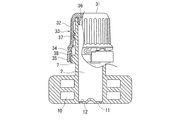
図1〜図6に示すように、本発明のキャップ付スパウトは、それぞれ別々に成形されたスパウト1とスパウト1に螺子係合により脱着可能に適用されるキャップ30から成っている。
スパウト1は、概略的に言って、内部に内容物の注出路となる空間2(以下、注出路2ということがある)が貫通している筒状本体3と、筒状本体3の下部に位置し、スパウト1を袋状包装体(図示せず)に固着するための溶着部4から成っている。筒状本体3の上部外面には、キャップ30と螺子係合するための螺子部5、後述するキャップ30のキャップ本体の内周面下部に形成された段差部下面と密着してキャップ内への薬液の浸入を防止するための環状突起6及びキャップ30のタンパーエビデントバンドを破断するための複数個の突起7,7,・・・が形成されている。溶着部4は、頂板部8及びこの頂板部8の周縁から下方に延びる溶着面9を有しており、この溶着面9に袋状包装体が溶着される。図に示す具体例においては、溶着部4には、使用樹脂を削減するために、図面の奥行き方向に延びる貫通孔10,10,・・・が複数個設けられている。
The present invention will be described with reference to the accompanying drawings.
As shown in FIGS. 1-6, the spout with a cap of this invention consists of the
Generally speaking, the
キャップ30は、概略的に言って、天面31及び天面31から垂下するスカート部32から成るキャップ本体33と、スカート部32の下端に破断可能な弱化部34を介して一体に成形されたタンパーエビデントバンド35から成っている。
キャップ本体33の天面の31の内面には、スパウトの筒状本体3の上部の内面と密着するインナーリング36が形成されている。またスカート部32の内面には、スパウトの筒状本体3の螺子部5と係合する螺子部37が形成されている。
更にタンパーエビデントバンド35の内面には、スパウトの筒状本体3の外面に形成された複数個の突起7,7,・・・と係合する複数個のラチェット片38,38,・・・が形成されている。これにより、開封のためにキャップ30を旋回すると、突起7,7,・・・とラチェット片38,38,・・・が周方向に係合してタンパーエビデントバンド35はキャップ本体30の旋回に追従することなくスパウトに残り、一旦開封されたものであることを明示することができる。
尚、図に示す具体例においては、キャッピング時にキャップ本体33とタンパーエビデントバンド35の間の破断可能な弱化部34が破断されてしまうことを防止するために、タンパーエビデントバンド35の上端に、キャッピング時にキャップ本体スカート部下端と軸方向及び周方向に当接可能な突起39が形成されている。突起39がキャップ本体33のスカート部32下端に形成された係合凸部40及び係合凸部40,40の間の凹部41と係止することになる。
Generally speaking, the
An
Further, on the inner surface of the tamper
In the specific example shown in the figure, in order to prevent the breakable weakened
本発明のキャップ付スパウトは、上述した基本構造において、内容物の注出路2となる開口を閉塞する薄膜部11が形成されていること、及びこの薄膜部11に上面から、薄膜部11の中央を中心とする円周状スコア12が形成されており、この円周状スコア12は、図7に示すように、円弧ABが破断不可能な円弧状スコア12aであり、他の部分の円弧BCDAが破断可能なスコア12bとして形成されている。
また破断不可能な円弧状スコア12aの両端部A,Bには、半径方向外方に延びる一対の破断可能な径方向スコア13a,13bが形成されており、この一対の径方向スコア13a,13bの間であって、破断不可能な円弧状スコア12aよりも外周側に位置する部分に、破断不可能な外周側円弧状スコア14が形成されていることが重要な特徴である。
すなわち、本発明においては、薄膜部11が開口を閉塞していることにより、予め電子線殺菌等で殺菌されたキャップ付スパウトの内部は無菌状態が維持され、その後薬液による殺菌の際に、薬液が筒状本体3の内部に浸入することがなく、スパウト内部に薬液が残存することによる問題を生じることが有効に防止されている。
また、薄膜部11に形成される円周状スコア(破断不可能な円弧状スコア12a,破断可能な円弧状スコア12b)、径方向スコア13a,13b及び外周側円弧状スコア14は薄膜部11の上面、すなわち、筒状本体の内側に形成されていることにより、スコア或いは薄肉部の溝に薬液が付着することがなく、薬液の残存が確実に防止されている。
In the spout with a cap according to the present invention, in the basic structure described above, the
A pair of breakable
That is, in the present invention, since the
Further, the circumferential score formed on the thin film portion 11 (the arc-shaped
本発明のキャップ付スパウトにおいて、円周状スコア12で区画される薄膜部11の中央部分15は、破断不可能な円弧状スコア12aをヒンジとして注出路内に押し込まれるが、破断不可能な円弧状スコア12aが円弧をなし、円弧ABの両端部が円弧の中央部よりも中央部分15の復元方向側に位置していることから、中央部分15が元の位置に戻ることを有効に阻止できる。しかも破断不可能な円弧状スコア12aよりも外周側に破断不可能な外周側円周状スコア14が更に位置し、二重の円弧を形成している結果、ヒンジの曲がりが維持されやすく、薄膜部11の中央部分15が注出路2内に押し込まれた状態を安定して維持することができ、注出路を確実に連通した状態が維持される。
尚、図に示す具体例においては、薄膜部11の上面には、上記必須のスコアの他に、外周側円弧状スコア14と同一円周上に破断不可能な円弧状スコア16a,16b,16c,16dが形成されていると共に、破断可能な径方向スコア13a,13bと対照の位置に半径方向外方に延びる破断可能な径方向スコア17a,17bが形成されている。
これにより、スコアを切断するためのカッター等の切断手段50により、薄膜部11が下方から押圧されると破断可能な円弧状スコア12bが切断され、次いでスコア切断手段が注出路内に進入するに従って、破断可能な径方向スコア13a,13b,17a,17bが破断されることにより、切断手段を注出路内にスムーズに押し込むことが可能になる。
更に、破断不可能な外周側円弧状スコア14を含む円周上に、破断不可能な円弧状スコア16a,16b,16c,16dが形成されていることにより、径方向スコア13a,13b,17a,17bにより分断された薄膜部の開口端縁が切断手段の進入に伴い、注出路内に折れ曲がりやすくなり、充分な大きさの注出開口を確保でき、内容物の流通も容易になる。
In the spout with a cap according to the present invention, the
In the specific example shown in the figure, on the upper surface of the
Thereby, when the
Further, the arc-shaped
図1及び図5に示すように、本発明のキャップ付スパウトにおいては、薄膜部11が中心から周縁部にかけて中心を頂点とする傾斜面を形成するように、中心が上方に向かって凸になっていることが好適である。これにより、中央部にスコア切断手段の先端が位置しやすくなり、破断可能な円弧状スコア12bから径方向スコア13a,13b,17a,17bを均等に破断することができる。
また本発明においては、円周状スコア12の径D1(図7参照)を、薄膜部の切断に用いられるカッター等の切断手段50の先端部分の径D2(図8参照)の大きさと略同等乃至若干小さい径にすることにより、切断手段によるスコアの切断が容易になると共に、薄膜部の中央部分の注出路内への押し込みが容易になる。
As shown in FIGS. 1 and 5, in the spout with a cap according to the present invention, the center is convex upward so that the
In the present invention, the diameter D1 (see FIG. 7) of the
本発明のキャップ付スパウトにおいてはこれに限定されるものではないが、予め電子線殺菌等によって殺菌されたキャップ付スパウトの溶着部の一方の面或いは両面を袋状包装体に溶着した後、包装体と共に薬液に浸漬或いは薬液が噴霧されることにより殺菌される。次いで、風圧で薬液が除去された後、薄膜部の切断及び切断された薄膜部の筒状本体への押し込みが行われ、これによりスパウトの外面は勿論内部にいたるまで薬液が残存することが有効に防止される。 The spout with a cap according to the present invention is not limited to this. After one or both surfaces of the welded portion of the spout with a cap previously sterilized by electron beam sterilization or the like are welded to the bag-shaped package, the packaging is performed. It is sterilized by being immersed in the chemical solution with the body or sprayed with the chemical solution. Next, after the chemical solution is removed by wind pressure, the thin film portion is cut and the cut thin film portion is pushed into the cylindrical body, so that it is effective that the chemical solution remains until the outer surface of the spout reaches the inside. To be prevented.
本発明のキャップ付スパウトにおいては、上述した具体例に限定されず、種々の変更が可能である。
例えば、破断不可能な円弧状スコアの中心角は、図に示す具体例では90°であったが、この部分がヒンジとしての機能を果たす限りこれに限定されず、特に45乃至120°の範囲にあることが好ましい。
また破断不可能な円弧状スコア12a(円弧AB)は、ヒンジとしての折れ曲がりやすさを維持し且つ破断されることがない限り、その形態やスコア深さなどに制限はないが、図7に示すように、連続したスコアとして形成されていることが、ヒンジとしての折曲がりやすさの点から望ましい。一方外周側円弧状スコア14は必ずしも連続したスコアでなくてもよく、いくつかに分断されていてもよい(図7では2つに分断)。
また破断可能な径方向スコアは、図7に示す具体例では、4個が均等に形成されていたが、これに限定されず、円周状スコアのうち破断不可能な円弧状スコアを除く、破断可能な円弧状スコアに対して、均等に形成されていることが望ましく、その数も限定されないが、3〜8の範囲にあることが好ましい。
更に図7においては、外周側円弧状スコアと同一円周上に位置する、複数の破断不可能な円弧状スコアが形成されていたが、これに限定されず、外周側円弧状スコアを含む環状スコアとして形成されていても勿論よい。
The spout with a cap according to the present invention is not limited to the specific examples described above, and various modifications are possible.
For example, the center angle of the arc-shaped score that cannot be broken is 90 ° in the specific example shown in the figure, but is not limited to this as long as this portion functions as a hinge, and is particularly in the range of 45 to 120 °. It is preferable that it exists in.
Further, the arc-shaped
Further, in the specific example shown in FIG. 7, the breakable radial direction score was uniformly formed of four pieces, but is not limited to this, and excludes the non-breakable arc-shaped score from the circumferential score. It is desirable that the breakable arc-shaped score is uniformly formed, and the number thereof is not limited, but is preferably in the range of 3 to 8.
Further, in FIG. 7, a plurality of non-breakable arc-shaped scores located on the same circumference as the outer-circular arc-shaped score are formed. Of course, it may be formed as a score.
また図に示す具体例では、薄膜部は中心から周縁部にかけて中心を頂点とする傾斜面を形成していたが、薄膜部の下面中央に切断手段の先端を正確に案内し得る限りこれに限定されず、例えば、平坦な面或いは、薬液がたまらない程度の大きさの上方に突出する曲面で形成された凹部を薄膜部下面中央に形成する等種々の変更が可能である。
更に図に示した具体例では、タンパーエビデントバンドが形成されていたが、必ずしもタンパーエビデントバンドを設けなくてもよく、またキャップ部分をシュリンクフィルム等で覆う等して用いてもよい。
更にまた、溶着部には使用樹脂量を削減すると共に成形時のヒケ等の発生を抑制するためには凹部を形成することが望ましいが、薬液が残存することを防止すべく、図に示したような貫通孔とするか、或いは凹部に微細な角部が存在しないように曲面とすることが望ましい。
Further, in the specific example shown in the figure, the thin film portion formed an inclined surface with the center as the apex from the center to the peripheral portion, but it is limited to this as long as the tip of the cutting means can be accurately guided to the center of the lower surface of the thin film portion. However, for example, various modifications such as forming a flat surface or a concave portion formed with a curved surface projecting upward in such a size that the chemical solution does not accumulate can be made at the center of the lower surface of the thin film portion.
Further, in the specific example shown in the figure, the tamper evidence band is formed, but the tamper evidence band is not necessarily provided, and the cap portion may be used by covering it with a shrink film or the like.
Furthermore, it is desirable to form a recess in the welded portion in order to reduce the amount of resin used and to suppress the occurrence of sink marks and the like during molding, but this is shown in the figure in order to prevent chemicals from remaining. It is desirable to use such a through hole or a curved surface so that there are no fine corners in the recess.
本発明のキャップ付スパウトは、従来スパウトの成形に用いられていた、ポリエチレン、ポリプロピレン等の熱可塑性樹脂を用いて、スパウト及びキャップをそれぞれ従来公知の射出成形、圧縮成形等で成形し、これらを組み合わせることによって成形することができる。 The spout with a cap of the present invention is formed by using a thermoplastic resin such as polyethylene or polypropylene, which has been conventionally used for molding a spout, and molding the spout and cap by a conventionally known injection molding, compression molding, or the like. It can be molded by combining.
本発明のキャップ付スパウトは、薬液による殺菌を行っても、風圧等の簡易な手段で薬液を完全に除去することが可能であり、アセプティック充填が行われる袋状包装体に好適に使用することができる。 The spout with a cap of the present invention can be completely removed by a simple means such as wind pressure even when sterilized with a chemical solution, and should be suitably used for a bag-like package in which aseptic filling is performed. Can do.
1 スパウト、2 注出路、3 筒状本体、4 溶着部、11 薄膜部、12 円周状スコア、12a 破断不可能な円弧状スコア,12b 破断可能な円弧状スコア、13 破断可能な径方向スコア、14 破断不可能な外周側円弧状スコア、30 キャップ、50切断手段。
DESCRIPTION OF
Claims (3)
前記溶着部の底面には、内容物の注出路となる開口を閉塞する薄膜部が形成されており、該薄膜部の上面には、薄膜部の中央を中心とする円周状スコアが形成されており、該円周状スコアは、一部の円弧が破断不可能な円弧状スコアであり、他の部分のスコアが破断可能な円弧状スコアとして形成されており、該破断不可能な円弧状スコアの両端には、該端部から半径方向外方に延びる一対の破断可能な径方向スコアが形成されており、該一対の径方向スコアの間の前記破断不可能な円弧状スコアよりも外周側に位置する部分に、破断不可能な外周側円弧状スコアが形成されており、
前記薄膜部を下面側から押圧することにより、前記破断可能な円弧状スコアが破断され、前記破断不可能な円弧状スコアをヒンジとして、破断可能な円弧状スコア及び径方向スコアで区画される薄膜部の中央部分が、注出路内部に押し込まれることにより注出路が形成されると共に、前記外周側円弧状スコアにより前記円周状スコアによるヒンジの戻りを防止して、注出路を維持することを特徴とするキャップ付スパウト。 It consists of a cylindrical main body through which a space serving as a discharge path for the content liquid penetrates, and a welded portion located at the lower part of the cylindrical main body and having a weld surface extending downward from the periphery of the top plate portion. A spout with a cap comprising a spout and a cap engaged with the spout,
A thin film portion is formed on the bottom surface of the welded portion to close the opening serving as a content extraction path, and a circumferential score centering on the center of the thin film portion is formed on the upper surface of the thin film portion. The circumferential score is an arc-shaped score in which some arcs cannot be broken, and the score in the other portion is formed as a breakable arc-shaped score. A pair of breakable radial scores extending radially outward from the ends are formed at both ends of the score, and the outer periphery of the unbreakable arc score between the pair of radial scores In the part located on the side, an outer peripheral arc-shaped score that cannot be broken is formed,
By pressing the thin film portion from the lower surface side, the breakable arc-shaped score is broken, and the thin film is divided by the breakable arc-shaped score and the radial score using the unbreakable arc-shaped score as a hinge The center portion of the part is pushed into the pouring path to form a pouring path, and the outer circumferential side arc-shaped score prevents the return of the hinge by the circumferential score, and maintains the pouring path. Spout with cap as a feature.
Priority Applications (5)
| Application Number | Priority Date | Filing Date | Title |
|---|---|---|---|
| JP2012226876A JP6096463B2 (en) | 2012-10-12 | 2012-10-12 | Spout with cap for aseptic filling |
| US14/435,075 US9493284B2 (en) | 2012-10-12 | 2013-09-13 | Capped spout |
| EP13844974.9A EP2913278B1 (en) | 2012-10-12 | 2013-09-13 | Capped spout |
| PCT/JP2013/074796 WO2014057767A1 (en) | 2012-10-12 | 2013-09-13 | Capped spout |
| CN201380052734.8A CN104755380B (en) | 2012-10-12 | 2013-09-13 | Suction nozzle with cover |
Applications Claiming Priority (1)
| Application Number | Priority Date | Filing Date | Title |
|---|---|---|---|
| JP2012226876A JP6096463B2 (en) | 2012-10-12 | 2012-10-12 | Spout with cap for aseptic filling |
Publications (2)
| Publication Number | Publication Date |
|---|---|
| JP2014076846A JP2014076846A (en) | 2014-05-01 |
| JP6096463B2 true JP6096463B2 (en) | 2017-03-15 |
Family
ID=50477238
Family Applications (1)
| Application Number | Title | Priority Date | Filing Date |
|---|---|---|---|
| JP2012226876A Active JP6096463B2 (en) | 2012-10-12 | 2012-10-12 | Spout with cap for aseptic filling |
Country Status (5)
| Country | Link |
|---|---|
| US (1) | US9493284B2 (en) |
| EP (1) | EP2913278B1 (en) |
| JP (1) | JP6096463B2 (en) |
| CN (1) | CN104755380B (en) |
| WO (1) | WO2014057767A1 (en) |
Families Citing this family (4)
| Publication number | Priority date | Publication date | Assignee | Title |
|---|---|---|---|---|
| WO2015073891A1 (en) * | 2013-11-14 | 2015-05-21 | Csm Bakery Products Na, Inc. | Fitment coupler with cap |
| PL232709B1 (en) * | 2016-12-19 | 2019-07-31 | Dariusz Jerzy Krajewski | Feeder with a screw cap for sachets |
| US10442582B1 (en) * | 2018-08-14 | 2019-10-15 | Phoenix Closures, Inc. | Spout fitment apparatus for a flexible container |
| JP7254281B2 (en) * | 2019-01-31 | 2023-04-10 | シロウマサイエンス株式会社 | Spout caps, spouts and spouted containers |
Family Cites Families (14)
| Publication number | Priority date | Publication date | Assignee | Title |
|---|---|---|---|---|
| US3029987A (en) * | 1959-09-28 | 1962-04-17 | Container Corp | Spout with frangible diaphragm for caulking cartridge |
| US3643833A (en) * | 1969-11-04 | 1972-02-22 | Ermal C Fraze | Easy opening container wall |
| US4709835A (en) * | 1984-03-13 | 1987-12-01 | Coca-Cola Company | Dispenser pouch for beverage syrups and concentrates |
| US5505235A (en) * | 1994-02-22 | 1996-04-09 | Gorokhovsky; Mark | Container having a breakable pouring cap |
| US5642838A (en) * | 1995-12-28 | 1997-07-01 | Stoody; William Robert | Frangible sealing lid for spile access |
| US6206222B1 (en) * | 1997-08-28 | 2001-03-27 | Ball Corporation | Resealable closure on seamed can end |
| JP2004067184A (en) * | 2002-08-07 | 2004-03-04 | Dainippon Printing Co Ltd | Container with spout, and spout |
| DE102005006871A1 (en) * | 2004-11-04 | 2006-05-11 | Georg Menshen Gmbh & Co. Kg | Plastic pouring weld |
| JP2007161254A (en) * | 2005-12-09 | 2007-06-28 | Dainippon Printing Co Ltd | Container with spout |
| JP5306587B2 (en) | 2006-09-29 | 2013-10-02 | 東洋製罐株式会社 | Spout having gas barrier property, method for producing the same, and container with spout equipped with the spout |
| JP5306783B2 (en) * | 2008-11-17 | 2013-10-02 | ザ コカ・コーラ カンパニー | Spout cap |
| JP5009329B2 (en) | 2009-03-10 | 2012-08-22 | 三笠産業株式会社 | Pouch with spout |
| JP5937331B2 (en) * | 2011-10-14 | 2016-06-22 | オリヒロエンジニアリング株式会社 | Spout with cap for aseptic filling |
| US8844761B2 (en) * | 2012-08-10 | 2014-09-30 | Daniel A. Zabaleta | Resealable beverage containers and methods of making same |
-
2012
- 2012-10-12 JP JP2012226876A patent/JP6096463B2/en active Active
-
2013
- 2013-09-13 EP EP13844974.9A patent/EP2913278B1/en active Active
- 2013-09-13 WO PCT/JP2013/074796 patent/WO2014057767A1/en active Application Filing
- 2013-09-13 CN CN201380052734.8A patent/CN104755380B/en active Active
- 2013-09-13 US US14/435,075 patent/US9493284B2/en active Active
Also Published As
| Publication number | Publication date |
|---|---|
| EP2913278A1 (en) | 2015-09-02 |
| WO2014057767A8 (en) | 2015-04-02 |
| CN104755380A (en) | 2015-07-01 |
| JP2014076846A (en) | 2014-05-01 |
| EP2913278A4 (en) | 2016-06-22 |
| WO2014057767A1 (en) | 2014-04-17 |
| EP2913278B1 (en) | 2017-05-10 |
| CN104755380B (en) | 2016-08-24 |
| US20150274391A1 (en) | 2015-10-01 |
| US9493284B2 (en) | 2016-11-15 |
Similar Documents
| Publication | Publication Date | Title |
|---|---|---|
| JP6307599B2 (en) | Cap with cutting element | |
| JP5857668B2 (en) | Container cap | |
| JP6096463B2 (en) | Spout with cap for aseptic filling | |
| JP5937331B2 (en) | Spout with cap for aseptic filling | |
| US7810681B2 (en) | Internal container bore mount fitment | |
| JP5461393B2 (en) | Closure member for sealed food container and method for producing the closure member | |
| EP3148885A1 (en) | Fitment for a flexible container | |
| JP2006341908A (en) | Spout | |
| JP4912689B2 (en) | Spout with cap holder | |
| JP2011105382A (en) | Spout plug and packing container | |
| JP2011235956A (en) | Spout for pouch and pouch using the same | |
| JP4061340B2 (en) | Hollow container with spout and its molding method | |
| JP4316706B2 (en) | Heat sterilization or sterilization method | |
| JP7386709B2 (en) | spout for food packaging | |
| JP5770591B2 (en) | Spout with cap for aseptic filling | |
| JP5770590B2 (en) | Spout with cap for aseptic filling | |
| JP5421653B2 (en) | Pouring tool | |
| JP2006176144A (en) | Spout | |
| JP2010215284A (en) | Spout device for paper container | |
| JP6911506B2 (en) | Mouth plug | |
| JP2012076786A (en) | Cap with opening blade | |
| JP2007062782A (en) | Hinge cap | |
| JP2010222017A (en) | Opening tool | |
| JP2006069556A (en) | Bung for paper-made liquid container with te function | |
| JP2007168842A (en) | Strapped cap |
Legal Events
| Date | Code | Title | Description |
|---|---|---|---|
| A621 | Written request for application examination |
Free format text: JAPANESE INTERMEDIATE CODE: A621 Effective date: 20150915 |
|
| A131 | Notification of reasons for refusal |
Free format text: JAPANESE INTERMEDIATE CODE: A131 Effective date: 20160927 |
|
| A521 | Request for written amendment filed |
Free format text: JAPANESE INTERMEDIATE CODE: A523 Effective date: 20161110 |
|
| TRDD | Decision of grant or rejection written | ||
| A01 | Written decision to grant a patent or to grant a registration (utility model) |
Free format text: JAPANESE INTERMEDIATE CODE: A01 Effective date: 20170124 |
|
| A61 | First payment of annual fees (during grant procedure) |
Free format text: JAPANESE INTERMEDIATE CODE: A61 Effective date: 20170216 |
|
| R150 | Certificate of patent or registration of utility model |
Ref document number: 6096463 Country of ref document: JP Free format text: JAPANESE INTERMEDIATE CODE: R150 |
|
| R250 | Receipt of annual fees |
Free format text: JAPANESE INTERMEDIATE CODE: R250 |
|
| R250 | Receipt of annual fees |
Free format text: JAPANESE INTERMEDIATE CODE: R250 |
|
| R250 | Receipt of annual fees |
Free format text: JAPANESE INTERMEDIATE CODE: R250 |
|
| R250 | Receipt of annual fees |
Free format text: JAPANESE INTERMEDIATE CODE: R250 |
|
| R250 | Receipt of annual fees |
Free format text: JAPANESE INTERMEDIATE CODE: R250 |
|
| S111 | Request for change of ownership or part of ownership |
Free format text: JAPANESE INTERMEDIATE CODE: R313117 |