JP6094866B2 - Illumination optics - Google Patents
Illumination optics Download PDFInfo
- Publication number
- JP6094866B2 JP6094866B2 JP2013004649A JP2013004649A JP6094866B2 JP 6094866 B2 JP6094866 B2 JP 6094866B2 JP 2013004649 A JP2013004649 A JP 2013004649A JP 2013004649 A JP2013004649 A JP 2013004649A JP 6094866 B2 JP6094866 B2 JP 6094866B2
- Authority
- JP
- Japan
- Prior art keywords
- light
- band
- phosphor
- optical system
- blue
- Prior art date
- Legal status (The legal status is an assumption and is not a legal conclusion. Google has not performed a legal analysis and makes no representation as to the accuracy of the status listed.)
- Active
Links
- 238000005286 illumination Methods 0.000 title claims description 32
- OAICVXFJPJFONN-UHFFFAOYSA-N Phosphorus Chemical group [P] OAICVXFJPJFONN-UHFFFAOYSA-N 0.000 claims description 100
- 230000003287 optical effect Effects 0.000 claims description 74
- 239000012141 concentrate Substances 0.000 claims description 3
- 239000000758 substrate Substances 0.000 description 20
- 239000000463 material Substances 0.000 description 13
- 238000006243 chemical reaction Methods 0.000 description 11
- 239000004065 semiconductor Substances 0.000 description 8
- 238000010586 diagram Methods 0.000 description 5
- 230000002093 peripheral effect Effects 0.000 description 4
- 230000005284 excitation Effects 0.000 description 3
- JNDMLEXHDPKVFC-UHFFFAOYSA-N aluminum;oxygen(2-);yttrium(3+) Chemical compound [O-2].[O-2].[O-2].[Al+3].[Y+3] JNDMLEXHDPKVFC-UHFFFAOYSA-N 0.000 description 2
- 230000006866 deterioration Effects 0.000 description 2
- 229920006395 saturated elastomer Polymers 0.000 description 2
- 230000002194 synthesizing effect Effects 0.000 description 2
- 229910019901 yttrium aluminum garnet Inorganic materials 0.000 description 2
- 239000000853 adhesive Substances 0.000 description 1
- 230000001070 adhesive effect Effects 0.000 description 1
- FNCIDSNKNZQJTJ-UHFFFAOYSA-N alumane;terbium Chemical compound [AlH3].[Tb] FNCIDSNKNZQJTJ-UHFFFAOYSA-N 0.000 description 1
- 229910052782 aluminium Inorganic materials 0.000 description 1
- XAGFODPZIPBFFR-UHFFFAOYSA-N aluminium Chemical compound [Al] XAGFODPZIPBFFR-UHFFFAOYSA-N 0.000 description 1
- FZTPSPNAZCIDGO-UHFFFAOYSA-N barium(2+);silicate Chemical compound [Ba+2].[Ba+2].[O-][Si]([O-])([O-])[O-] FZTPSPNAZCIDGO-UHFFFAOYSA-N 0.000 description 1
- 229910010293 ceramic material Inorganic materials 0.000 description 1
- 230000006378 damage Effects 0.000 description 1
- 230000002542 deteriorative effect Effects 0.000 description 1
- 238000009792 diffusion process Methods 0.000 description 1
- 238000000605 extraction Methods 0.000 description 1
- 230000004907 flux Effects 0.000 description 1
- 239000002223 garnet Substances 0.000 description 1
- 239000011521 glass Substances 0.000 description 1
- 230000001678 irradiating effect Effects 0.000 description 1
- 239000007769 metal material Substances 0.000 description 1
- -1 nitride compound Chemical class 0.000 description 1
- 239000013307 optical fiber Substances 0.000 description 1
- 239000011347 resin Substances 0.000 description 1
- 229920005989 resin Polymers 0.000 description 1
- 230000001360 synchronised effect Effects 0.000 description 1
- 230000003685 thermal hair damage Effects 0.000 description 1
Images


Description
本発明は、青色帯域のレーザ光等を発するアレイ光源を用いた照明光学系に関し、特にプロジェクタや照明装置等の電子装置等の光源に用いられる照明光学系に関する。 The present invention relates to an illumination optical system using an array light source that emits a laser beam in a blue band, and more particularly to an illumination optical system used as a light source of an electronic device such as a projector or a lighting device.
プロジェクタの光源ユニットに、青色レーザ発光器を光源に利用したのが知られている(特許文献1)。この光源ユニットは、青色レーザ発光器と、蛍光体ホイールと、複数の反射ミラーやダイクロイックミラーとを備えて構成される。蛍光体ホイールは、モータによって回転される円板形状を有し、蛍光体ホイールには、青色帯域の光を透過する透過部、および青色帯域の光を赤色帯域および緑色帯域の光を発する蛍光体層がそれぞれ形成されている。 It is known that a blue laser light emitter is used as a light source for a light source unit of a projector (Patent Document 1). This light source unit includes a blue laser light emitter, a phosphor wheel, and a plurality of reflection mirrors and dichroic mirrors. The phosphor wheel has a disk shape rotated by a motor, and the phosphor wheel has a transmitting portion that transmits light in the blue band and a phosphor that emits light in the blue band and emits light in the red band and green band. Each layer is formed.
上記特許文献1に示される光源ユニットは、蛍光体ホイールが青色帯域の光を透過する構成であるため、その光学系のレイアウト等に制約が生じてしまい、必ずしも光源ユニットの小型化、省スペース化に適しているとはいえなかった。 Since the light source unit shown in Patent Document 1 has a configuration in which the phosphor wheel transmits light in the blue band, there are restrictions on the layout of the optical system and the like, and the light source unit is necessarily downsized and space-saving. It could not be said that it was suitable for.
そこで、本発明は、光学部品の点数を減らし、省スペース、軽量化、低コスト化を図る照明光学系およびこれを用いた電子装置を提供することを目的とする。
さらに本発明は、青色帯域の光と、赤色帯域および緑色帯域の光の混色を効果的に防止することができる回転体およびそれを用いた照明光学系を提供することを目的とする。
Therefore, an object of the present invention is to provide an illumination optical system capable of reducing the number of optical components, saving space, reducing weight, and reducing cost, and an electronic device using the same.
Another object of the present invention is to provide a rotating body capable of effectively preventing color mixing of light in the blue band and light in the red band and the green band, and an illumination optical system using the rotating body.
本発明に係る回転体は、青色帯域に光を入射し、少なくとも青色帯域、赤色帯域および緑色帯域の光を発生させるものであって、前記回転体は、第1の面と、当該第1の面に対向する第2の面とを有し、前記第1の面には、少なくとも青色帯域の光を反射する反射領域と、青色帯域の光を透過し少なくとも赤色帯域および緑色帯域の光を反射するダイクロイック領域とが形成され、前記第2の面には、前記ダイクロイック領域を透過した青色帯域の光に基づき赤色帯域の光を発光する第1の蛍光体領域および緑色帯域の光を発光する第2の蛍光体領域が形成される。好ましい態様では、第1の面上の反射領域は、反射ミラー、反射層、反射部材、反射フィルターなどによって構成される。また、第1の面上に形成されるダイクロイック領域は、ダイクロイックミラーやダイクロイックフィルターから構成される。さらに好ましい態様では、前記第1および第2の蛍光体領域は、前記第2の面の半径方向に複数組形成されるようにしてもよい。さらに好ましくは、前記回転体は、第1の面および当該第1の面と対向する第2の面を有する透明基板を含み、前記反射領域および前記ダイクロイック領域は、前記透明基板の第1の面上に形成され、前記第1および第2の蛍光体領域は、前記透明基板の第2の面上に形成される。 The rotating body according to the present invention is for injecting light into a blue band to generate light in at least a blue band, a red band, and a green band, and the rotating body has a first surface and the first surface. It has a second surface facing the surface, and the first surface has a reflection region that reflects light in at least the blue band and a reflection region that transmits light in the blue band and reflects light in at least the red band and the green band. A dichroic region is formed, and on the second surface, a first phosphor region that emits light in the red band based on the light in the blue band transmitted through the dichroic region and a first phosphor region that emits light in the green band and light in the green band are emitted. Two phosphor regions are formed. In a preferred embodiment, the reflective region on the first surface is composed of a reflective mirror, a reflective layer, a reflective member, a reflective filter, and the like. Further, the dichroic region formed on the first surface is composed of a dichroic mirror and a dichroic filter. In a more preferred embodiment, a plurality of sets of the first and second phosphor regions may be formed in the radial direction of the second surface. More preferably, the rotating body includes a transparent substrate having a first surface and a second surface facing the first surface, and the reflection region and the dichroic region are the first surface of the transparent substrate. Formed on top, the first and second phosphor regions are formed on the second surface of the transparent substrate.
本発明に係る照明光学系は、上記記載の回転体と、青色帯域の光を発する光源と、前記回転体と前記光源の間に配され、前記光源からの青色帯域の光を第1の光軸に集光する第1の光学系と、前記第1の光軸からシフトされた第2の光軸を有し、前記第1の光学系によって集光された青色帯域の光を前記回転体に集光させる第2の光学系とを有する。好ましい態様では、前記第1の光学系によって集光された光は、前記第2の光学系のレンズの片側半分に入射される。照明光学系はさらに、前記回転体から発せられた赤色帯域および緑色帯域の光を集光する集光レンズを含むことができる。照明光学系はさらに、前記光源からの青色帯域の光をn組(nは、2以上の整数)の光に分割する分割部材を含むことができる。照明光学系はさらに、前記集光レンズで集光された光を反射するダイクロイックミラーを含むことができ、当該ダイクロイックミラーは、青色帯域の光を反射し、少なくとも赤色帯域および緑色帯域の光を透過する。照明光学系はさらに、前記集光レンズで集光された光を反射するダイクロイックミラーを含むことができ、当該ダイクロイックミラーは、青色帯域の光を透過し、少なくとも赤色帯域および緑色帯域の光を反射する。 The illumination optical system according to the present invention is arranged between the rotating body described above, a light source that emits light in the blue band, and the rotating body and the light source, and the light in the blue band from the light source is used as the first light. The rotating body has a first optical system that focuses on an axis and a second optical axis that is shifted from the first optical axis, and collects light in the blue band that is focused by the first optical system. It has a second optical system that concentrates light on the surface. In a preferred embodiment, the light focused by the first optical system is incident on one half of the lens of the second optical system. The illumination optical system can further include a condenser lens that collects the red band and green band light emitted from the rotating body. The illumination optical system can further include a dividing member that divides the light in the blue band from the light source into n sets (n is an integer of 2 or more). The illumination optical system can further include a dichroic mirror that reflects the light collected by the condenser lens, and the dichroic mirror reflects light in the blue band and transmits light in at least the red band and the green band. To do. The illumination optical system can further include a dichroic mirror that reflects the light collected by the condenser lens, and the dichroic mirror transmits light in the blue band and reflects light in at least the red band and the green band. To do.
本発明によれば、部品点数を削減し、小型化、軽量化、低コスト化を図った照明光学系およびそれを用いた電子装置を提供することができる。さらに本発明の回転体を用いることで、青色帯域の光が赤色帯域および緑色帯域の光に混色するのを効果的に防止することができる。 According to the present invention, it is possible to provide an illumination optical system in which the number of parts is reduced, and the size, weight, and cost are reduced, and an electronic device using the same. Further, by using the rotating body of the present invention, it is possible to effectively prevent the light in the blue band from being mixed with the light in the red band and the green band.
次に、本発明の実施の形態について図面を参照して詳細に説明する。本発明の好ましい態様では、照明光学系には、波長が短い青色光を発する半導体発光素子として、青色レーザ素子または青色発光ダイオードをアレイ化したアレイ光源が利用される。照明光学系は、青色帯域の光を利用し、それよりも波長の長い赤色帯域、緑色帯域、あるいは黄色帯域等の光を発生させるために、光軸がシフトされたシフト光学系、および波長変換のための蛍光体領域が形成された回転体を用いる。なお、図面のスケールは、発明の特徴を分かり易くするために強調しており、必ずしも実際のデバイスのスケールと同一ではないことに留意すべきである。 Next, an embodiment of the present invention will be described in detail with reference to the drawings. In a preferred embodiment of the present invention, the illumination optical system utilizes a blue laser element or an array light source in which a blue light emitting diode is arrayed as a semiconductor light emitting element that emits blue light having a short wavelength. The illumination optical system uses light in the blue band, and the optical axis is shifted in order to generate light in the red band, green band, or yellow band having a longer wavelength, and wavelength conversion. A rotating body in which a phosphor region for the above is formed is used. It should be noted that the scale of the drawings is emphasized for the sake of clarity of the features of the invention and is not necessarily the same as the scale of the actual device.
図1は、本発明の第1の実施例に係る照明光学系の基本原理を説明する図である。なお、以下の説明で、赤色帯域の光、緑色帯域の光、青色帯域の光を、便宜上、R、G、Bと略すことがある。 FIG. 1 is a diagram illustrating a basic principle of an illumination optical system according to a first embodiment of the present invention. In the following description, red band light, green band light, and blue band light may be abbreviated as R, G, and B for convenience.
本実施例の照明光学系10は、励起光としての青色帯域のレーザ光Lbを出射するアレイ光源20と、アレイ光源20からのレーザ光Lbを集光する前群レンズL1、L2と、前群レンズL1、L2によって集光されたレーザ光Lbを蛍光体ホイール30上に集光する後群レンズL3と、青色帯域のレーザ光Lbを選択的に反射および透過する領域を含み、かつ透過された青色帯域のレーザ光Lbによって励起され赤色帯域の光Lrおよび緑色帯域の光Lbを発光する蛍光体領域を備えた円盤状の蛍光体ホイール30と、蛍光体ホイール30の中心軸に結合され蛍光体ホイール30を回転するモータ40と、蛍光体ホイール30の入射面側で反射された青色帯域のレーザ光Lbを一定方向に反射する反射ミラー50と、蛍光体ホイール30の出射面側から出射された赤色帯域の光Lr、および緑色帯域の光Lgを集光する集光レンズL4と、集光レンズL4によって集光された赤色帯域および緑色帯域の光Lr/Lbを一定方向に反射する反射ミラー60を含んで構成される。
The illumination optical system 10 of this embodiment includes an
アレイ光源20は、青色帯域のレーザ光を出射する半導体レーザ素子(または青色発光ダイオード)をアレイ状に複数含んで構成される。半導体レーザ素子は、一次元または二次元に配列され、複数の半導体レーザ素子を同時に駆動することで、各半導体レーザ素子から一斉にレーザ光が出射される。
The
図2は、アレイ光源の一構成例を示す概略断面図である。同図に示すように、複数の半導体レーザ素子を搭載する基板は、熱伝導性の高い金属材料、例えばアルミニウムのような材料によって構成された支持部材22によって支持される。また、支持部材22の表面には、各半導体レーザ素子から出射されたレーザ光をそれぞれコリメートするレンズ24が取り付けられる。さらに支持部材22と対向する側には、反射ミラー26が配置され、反射ミラー26は、各半導体レーザ素子から出射された青色帯域の光を一定方向に反射し、レーザ光線束Lbを生成する。
FIG. 2 is a schematic cross-sectional view showing a configuration example of an array light source. As shown in the figure, a substrate on which a plurality of semiconductor laser elements are mounted is supported by a
前群レンズL1は、例えば平凸レンズ等から構成され、前群レンズL2は、例えば凹レンズから構成され、前群レンズL1、L2は、アレイ光源20からのレーザ光線Lbを平行光に集光する。前群レンズL1、L2の光軸C1は、レンズL1、L2の中心である。この例では、前群レンズとして2つの組合せレンズを用いているが、前群レンズは、アレイ光源20からのレーザ光Lbを集光することができる光学系であれば良く、前群レンズを構成するレンズの数は、1つであってもよいし、あるいは3つ以上であってもよい。さらに前群レンズは、球面レンズ、非球面レンズのいずれから構成されるものであってもよい。さらに前群レンズは、プリズム等の光学部材を含むものであってもよい。
The front group lens L1 is composed of, for example, a plano-convex lens, the front group lens L2 is composed of, for example, a concave lens, and the front group lenses L1 and L2 focus the laser beam Lb from the array
後群レンズL3は、例えば平凸レンズから構成され、前群レンズL1、L2で集光された光を入射し、これを蛍光体ホイール30上に集光する。後群レンズL3の光軸C2は、レンズL3の中心である。ここで留意すべき点は、本実施例の照明光学系10は、後群レンズの光軸C2は、前群レンズの光軸C1からシフトされた光学系であり、前群レンズL1、L2によって集光されたレーザ光Lbは、後群レンズL3の片側半分に入射されるように、光軸C1、C2のシフト量が調整される。図の例では、後群レンズL3は、1つのレンズを用いて構成されるが、後群レンズは、レーザ光Lbを蛍光体ホイール30上に集光することができるシフト光学系であれば良く、後群レンズを構成するレンズの数は、複数の組合せレンズであってもよい。さらに後群レンズは、球面レンズ、非球面レンズのいずれから構成されるものであってもよい。さらに後群レンズは、プリズム等の光学部材を含むものであってもよい。
The rear group lens L3 is composed of, for example, a plano-convex lens, incident light focused by the front group lenses L1 and L2, and focused the light on the
蛍光体ホイール30は、後群レンズL3と集光レンズL4との間に配され、後群レンズL3からの青色帯域のレーザ光Lbを正規反射し、かつ透過した青色帯域のレーザ光によって励起された赤色帯域および緑色帯域の光を反対側の面から出射させる。蛍光体ホイールについては後に詳細に説明する。
The
集光レンズL4は、例えば平凸レンズから構成され、蛍光体ホイール30の出射面側から発せられた赤色帯域および緑色帯域の光を集光する。集光レンズL4の光軸C3は、レンズL4の中心であり、好ましくは光軸C3は、光軸C2と一致する。この例では、集光レンズL4は、1つのレンズを用いて構成されるが、集光レンズは、蛍光体ホイール30から発せられた赤色帯域および緑色帯域の光を集光することができる光学系であれば良く、集光レンズを構成するレンズの数は、複数の組合せであってもよい。さらに集光レンズは、球面レンズ、非球面レンズのいずれから構成されるものであってもよい。
The condensing lens L4 is composed of, for example, a plano-convex lens, and condenses light in the red band and the green band emitted from the exit surface side of the
反射ミラー60は、集光レンズL4で集光された赤色帯域および緑色帯域の光を、例えば光軸C3と直交する方向に反射する。反射ミラー60は、青色、赤色および緑色の全波長帯域の光を反射する全反射ミラーから構成されてもよいし、あるいは青色帯域の光を透過し、赤色および緑色帯域の光を反射するダイクロイックミラーから構成されてもよい。後者の場合、蛍光体ホイール30で赤色帯域および緑色帯域の波長変換に利用されずに透過された青色帯域の光が、赤色帯域および緑色帯域の光に混色するのを効果的に防止することができる。
The
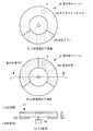
図3に本実施例の蛍光体ホイール30の構成例を示す。図3(A)は、蛍光体ホイール30の入射面側の平面図、図3(B)は、蛍光体ホイール30の出射面側の平面図、図3(C)は、図3(B)のX−X線断面図である。図中のPで示す円は、後群レンズL3によって集光された青色帯域の光Lbのスポットを表している。
FIG. 3 shows a configuration example of the
蛍光体ホイール30は、円盤状の透明基板32と、透明基板32の入射面側に形成されたダイクロイックミラー34Aおよび反射ミラー34Bと、透明基板32の出射面側に形成された蛍光体層36R、36Gとを含んで構成される。蛍光体ホイール30は、好ましくは円形状であるが、必ずしもこのような形状に限定されるものではなく、例えば、多角形上、楕円形状であってもよい。
The
透明基板32は、R、G、Bのすべての帯域の光を透過する材料から構成され、例えば、ガラスなどから構成される。ダイクロイックミラー34Aは、図3(A)に示すように、透明基板32の入射面側に形成され、青色帯域の光を透過し、赤色帯域および緑色帯域の光を反射する。図に示す例では、ダイクロイックミラー34Aは、ほぼ内角が240度の領域に扇状に形成される。が、このダイクロイックミラー34Aが形成される領域は、透明基板32の出射面側に形成される赤色帯域および緑色帯域の光を発色する蛍光体層36R、36Gの領域に一致しまたは重複する。なお、ダイクロイックミラー34Aは、ダイクロイックフィルターと同義である。
The
透明基板22の入射面側のダイクロイックミラー34Aが形成されない領域には、青色帯域の光Lbを反射する反射ミラー34Bが形成される。反射ミラー34Bは、少なくとも青色帯域の光を反射するダイクロイックミラーであってもよいし、R、G、Bの全帯域の光を反射する全反射ミラーであってもよい。反射ミラーは、反射層、反射部材、反射フィルターなどと同義である。
A
透明基板32の出射面側には、図3(B)に示すように、赤色帯域の光を発色する蛍光体層36R、および緑色帯域の光を発色する蛍光体層36Gが形成される。蛍光体層36Rは、ダイクロイックミラー32を透過した青色帯域の光によって励起されて赤色帯域の光を発光する。蛍光体層36Gは、ダイクロイックミラー32を透過した青色帯域の光によって励起されて緑色帯域の光を発光する。図に示す例では、蛍光体層36R、36Gは、ダイクロイックミラー34Aの大きさに対応し、それぞれの内角が120度の扇状に形成される。但し、これは一例であって、要求されるR、G、Bの輝度等に応じて蛍光体層36R、36G、ダイクロイックミラー34A、反射ミラー34Bのそれぞれの内角を適宜選択することができる。透明基板32の出射面側の蛍光体層36R、36Gが形成されない領域は、透明基板の表面が露出されている。
As shown in FIG. 3B, a
蛍光体層36R、36Gを構成する蛍光体材料には、YAG(イットリウム・アルミニウム・ガーネット)系、TAG(テルビウム・アルミニウム・ガーネット)系、サイアロン系、BOS(バリウム・オルソシリケート)系、窒化化合物系が知られている。蛍光体層36R、36Gは、例えば、蛍光体材料と樹脂材料やセラミック材料に混ぜ合わせたものを基材表面の塗布したり、蛍光体材料を混ぜ合わせたシート状のものと基材表面に貼り付けるようにしてもよい。
The fluorescent material constituting the
なお、上記の例では、蛍光体ホイール30には、赤色帯域および緑色帯域の光を発光させるための蛍光体層36R、36Gが形成されたが、青色レーザ光によって励起され、波長変換される光は、必ずしも赤色帯域および緑色帯域の光に限定されるものではない。例えば、黄色、マゼンタ、シアンの帯域の光が励起されるような蛍光体層を含むものであってもよい。
In the above example, the
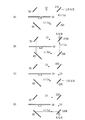
次に、本実施例の照明光学系の動作について説明する。図4(A)、(B)、(C)は、それぞれ青色帯域、緑色帯域、赤色帯域の光の発生を説明する模式的な図である。先ず、青色帯域の発生について図4(A)を参照して説明する。前群レンズL1、L2によって集光された青色帯域の光Lbは、光軸C2がシフトされた後群レンズL3の片側半分に入射され、入射された青色帯域の光は光軸C2に向けて偏向され、蛍光体ホイール30上に集光される。青色帯域の光Lbは、蛍光体ホイール30の反射ミラー34Bを照射するときに正規反射される。すなわち、青色帯域の光Lbは、光軸C2に関し反射ミラー34Bに入射角θ1で入射し、入射角θ1と等しい出射角θ2(θ1=θ2)で正規反射される。正規反射された光Lbは、後群レンズL3の反対側の片側半分に入射され、反射ミラー50に向けて集光される。
Next, the operation of the illumination optical system of this embodiment will be described. 4A, 4B, and 4C are schematic views illustrating the generation of light in the blue band, the green band, and the red band, respectively. First, the generation of the blue band will be described with reference to FIG. 4 (A). The light Lb in the blue band focused by the front group lenses L1 and L2 is incident on one half of the rear group lens L3 in which the optical axis C2 is shifted, and the incident blue band light is directed toward the optical axis C2. It is deflected and focused on the
次に、赤色帯域および緑色帯域の光の発生について図4(B)を参照して説明する。後群レンズL3からの青色帯域のレーザ光Lbが蛍光体ホイール30のダイクロイックミラー34Aを照射すると、その青色帯域の光Lbは、ダイクロイックミラー34Aおよび透明基板32を透過し、蛍光体層36Rまたは36Gに入射される。蛍光体材料は、青色帯域のレーザ光Lbによって励起され、赤色帯域または緑色帯域の光を発光する。図4(B)の模式図にあるように、青色帯域のレーザ光Lbによって励起された蛍光体の仮想的な発光点をWとしたとき、発光点Wからは等方的に、すなわちランバーシアン状(均一拡散)するように、RまたはBの光が放射される。このため、蛍光発色されたRまたはBの一部が蛍光体ホイール30の入射面側に進行するが、そのRまたはBの光は、ダイクロイックミラー34Aによって蛍光体ホイール30の出射面側へ反射されるので、RまたはGの抽出効率発を向上させ、R、Bの輝度を増加させることができる。
Next, the generation of light in the red band and the green band will be described with reference to FIG. 4 (B). When the laser beam Lb in the blue band from the rear lens group L3 irradiates the
こうして、蛍光体ホイール30を回転させることで、ダイクロイックミラー34Aおよび反射ミラー34BがスポットPによって光学的に走査され、蛍光体ホイール30の入射面側から青色帯域の光Lbが取り出され、出射面側から赤色帯域および緑色帯域の光Lr/Lgが取り出される。
By rotating the
照明光学系10によって発生されたR、G、Bの光は、プロジェクタや内視鏡などの光源に利用される。例えば、R、G、Bの光は、図示しないライトトンネルにシーケンシャルに入射され、そこから出射されたR、G、Bの光がデジタルミラーデバイス(DMD)を照明する。DMDは、複数のミラー素子が二次元アレイ状に形成され、各ミラー素子は、デジタル画像データに従い第1の角度または第2の角度に傾斜され、DMDによって反射されたR、G、Bの光は、投射画像を生成する。また、照明光学系10によって発生されたR、G、Bの光を合成することで白色光を生成し、これを光ファイバーに入射させ、内視鏡の光源とすることができる。 The R, G, and B lights generated by the illumination optical system 10 are used as a light source such as a projector or an endoscope. For example, the light of R, G, and B is sequentially incident on a light tunnel (not shown), and the light of R, G, and B emitted from the light tunnel illuminates the digital mirror device (DMD). In the DMD, a plurality of mirror elements are formed in a two-dimensional array, and each mirror element is tilted to a first angle or a second angle according to digital image data, and R, G, and B light reflected by the DMD. Generates a projected image. Further, white light can be generated by synthesizing the R, G, and B lights generated by the illumination optical system 10 and incident on an optical fiber to be used as a light source for an endoscope.
本実施例の照明光学系は、必要な光学部材を低減させ、コンパクトな構成を得ることができる。さらに本実施例の照明光学系では、蛍光体ホイールの入射面側から青色帯域の光を取り出し、出射面側から赤色帯域および緑色帯域の光を取り出すようにしたので、青色帯域の光が、赤色帯域および緑色帯域の光に混色することを効果的に抑制することができる。 The illumination optical system of this embodiment can reduce the number of required optical members and obtain a compact configuration. Further, in the illumination optical system of this embodiment, the light in the blue band is extracted from the incident surface side of the phosphor wheel, and the light in the red band and the green band is extracted from the exit surface side. Therefore, the light in the blue band is red. It is possible to effectively suppress color mixing with light in the band and the green band.
上記実施例に係る蛍光体ホイールは、透明基板の入射面側に、ダイクロイックミラー34Aおよび反射ミラー34Bの光学フィルター形成し、出射面側に蛍光体層36R、36Gの光学フィルターを形成する例を示したが、これは一例であり、蛍光体ホイールは、このような構成に限定されるものではない。例えば、蛍光体ホイールは、透明基板を用いることなく、ダイクロイックミラー34Aと反射ミラー34Bとの側面を接着剤等により接合し、そのダイクロイックミラーの裏面に、蛍光体層36R、36Bを直接積層または貼付するようにしてもよい。
The phosphor wheel according to the above embodiment shows an example in which the optical filters of the
さらに、上記実施例では、透明基板上に反射ミラー34Bを形成したが、反射ミラー34Bを形成する代わりに、透明基板の一部を、少なくとも青色帯域の光を反射する材料から構成するようにしてもよい。
Further, in the above embodiment, the
さらに、反射ミラー34Bの表面に、入射した青色帯域の光を微小に拡散させるような凹凸のある拡散面を形成し、青色レーザ光のスペックルを抑制するようにしてもよい。
Further, the surface of the
次に、本発明の第2の実施例について説明する。図5は、第2の実施例に係る照明光学系10Aを示しており、図1と同一構成については同一参照番号を付してある。第2の実施例では、同図に示すように、集光レンズL4と反射ミラー60との間に、ダイクロイックミラー70が設けられている。ダイクロイックミラー70は、青色帯域の光を反射し、それ以外の帯域の光、すなわちこの例では、赤色帯域および緑色帯域の光を透過するように構成される。ダイクロイックミラー70は、蛍光体ホイール30とほぼ平行に配置され、集光レンズL4によって集光された光を入射し、この光に含まれる青色帯域の光Lbを蛍光体ホイール30に向けて反射させる。
Next, a second embodiment of the present invention will be described. FIG. 5 shows the illumination optical system 10A according to the second embodiment, and the same reference number is assigned to the same configuration as that of FIG. In the second embodiment, as shown in the figure, a
後群レンズL3から蛍光体層36R、36Gに入射された青色帯域の光Lbの大部分は、蛍光体を励起し、赤色帯域および緑色帯域の光に変換されるが、一部の青色帯域の光Lbは、波長変換に利用されずに蛍光体層36R、36Gを透過することがある。そうすると、赤色および緑色帯域の光Lr/Lgに、青色帯域の光Lbが混色してしまい好ましくない。そこで、第2の実施例では、蛍光体層36R、36Gにおいて蛍光発色に寄与されずにそこを透過した青色帯域の光Lbをダイクロイックミラー70により反射させ、青色帯域の光Lbを蛍光体層36R、36G内へ入射させ、青色帯域の光を蛍光発色に再利用させる。これにより、蛍光体による変換効率が向上され、同時に、赤色帯域および緑色帯域の光に青色帯域の光が混色するのを防止することができる。
Most of the blue band light Lb incident on the phosphor layers 36R and 36G from the rear group lens L3 excites the phosphor and is converted into red band and green band light, but in some blue band. The light Lb may pass through the phosphor layers 36R and 36G without being used for wavelength conversion. Then, the light Lr / Lg in the red and green bands is mixed with the light Lb in the blue band, which is not preferable. Therefore, in the second embodiment, the light Lb in the blue band transmitted through the phosphor layers 36R and 36G without contributing to the fluorescence color development is reflected by the
次に、本発明の第3の実施例について説明する。図6は、第3の実施例に係る照明光学系10Bの原理を示す図である。第3の実施例は、第1の実施例で用いた後群レンズL3、集光レンズL4、反射ミラー50および反射ミラー60を2組備え、前群レンズL1、L2(図示しない)からの青色帯域のレーザ光Lbをビームスプリッター100で2つの光線束に分離し、それぞれの光学系からR、G、Bを生成するものである。但し、蛍光体ホイールは、複数用いることなく単数であり、その表面には、円周方向に2組の蛍光体層36R、36G等が形成される。
Next, a third embodiment of the present invention will be described. FIG. 6 is a diagram showing the principle of the illumination optical system 10B according to the third embodiment. The third embodiment includes two sets of the rear group lens L3, the condenser lens L4, the
同図に示すように、前群レンズL1、L2からの平行なレーザ光Lbは、ビームスプリッター100によって2つの光線束Lb1、Lb2に分離される。光線束Lb2はさらに、反射ミラー110によってほぼ直角に反射され、光線束Lb1と平行にされる。2つの光線束Lb1、Lb2は、第1の実施例のときと同様に、光軸がシフトされた2つの後群レンズL3のそれぞれ片側半分に入射される。光線束Lb1は、蛍光体ホイール30の外周側に集光され、スポットPで蛍光体ホイール30を光学的に走査し、光線束Lb2は、蛍光体ホール30の内周側に集光され、スポットQで蛍光体ホイールを光学的に走査する。蛍光体ホイール30で反射された青色帯域の光Lb1、Lb2は、2つの反射ミラー50によってそれぞれ反射された後、集光レンズL5によって合成される。
As shown in the figure, the parallel laser beam Lb from the front lens group lenses L1 and L2 is split into two ray bundles Lb1 and Lb2 by the
また、蛍光体ホイール30を透過した青色帯域の光Lb1、Lb2によって励起された赤色帯域および緑色帯域の光Lr、Lgは、2つの集光レンズL4によってそれぞれ集光された後、2つの反射ミラー60によってそれぞれ反射され、その後、集光レンズL6によって合成される。
Further, the red band and green band light Lr and Lg excited by the blue band light Lb1 and Lb2 transmitted through the
図6(C)は、スポットPおよびスポットQで蛍光体ホイールを走査したときのR、G、Bの合成輝度を表している。蛍光体ホイール30の外周側に形成される蛍光体層36R、36Gおよび反射ミラー34Bの配列と、内周側に形成される蛍光体層36R、36Gおよび反射ミラー34Bの配列は、R、G、Gが生成されるタイミングが同期するように調整される。
FIG. 6C shows the combined luminance of R, G, and B when the phosphor wheel is scanned at the spot P and the spot Q. The arrangement of the phosphor layers 36R, 36G and the
図7に、蛍光体の発光変換効率と励起光の照射エネルギー密度との関係を示す。蛍光体の特性として、光の照射エネルギー密度の増加に伴い、発光変換効率が増加する線形領域、発光変換効率が飽和する飽和領域、発光変換効率が劣化する劣化領域をもつことが知られている。このため、蛍光体層36R、36Gに一定以上のエネルギーの青色光が照射されると、発光変換効率が飽和ないし劣化し、蛍光体が熱損傷または熱劣化してしまう。熱損傷等を防止するためには、蛍光体層ないし蛍光体ホイールを冷却する必要がある。さらに、蛍光体は、経時変化によっても発光変換効率が劣化する。 FIG. 7 shows the relationship between the emission conversion efficiency of the phosphor and the irradiation energy density of the excitation light. It is known that the phosphor has a linear region in which the emission conversion efficiency increases, a saturation region in which the emission conversion efficiency is saturated, and a deterioration region in which the emission conversion efficiency deteriorates as the irradiation energy density of light increases. .. Therefore, when the phosphor layers 36R and 36G are irradiated with blue light having a certain energy or more, the emission conversion efficiency is saturated or deteriorated, and the phosphor is thermally damaged or deteriorated. In order to prevent heat damage and the like, it is necessary to cool the phosphor layer or the phosphor wheel. Further, the emission conversion efficiency of the phosphor deteriorates with time.
第3の実施例では、励起光としての青色帯域の光の照射エネルギーを高くしても、青色帯域の光を2分割し、蛍光体ホイール上に2組の蛍光体層を形成するようにしたので、蛍光体層に照射される照射エネルギーを実質的に半減させることができる。これにより、蛍光体を線形領域で使用することが可能になり、発光変換効率が劣化するのを防止することができる。同時に、蛍光体層の熱損傷または熱劣化を抑制することができ、蛍光体の寿命を延ばすことが可能になる。 In the third embodiment, even if the irradiation energy of the light in the blue band as the excitation light is increased, the light in the blue band is divided into two to form two sets of phosphor layers on the phosphor wheel. Therefore, the irradiation energy applied to the phosphor layer can be substantially halved. This makes it possible to use the phosphor in the linear region and prevent the emission conversion efficiency from deteriorating. At the same time, it is possible to suppress thermal damage or thermal deterioration of the phosphor layer, and it is possible to extend the life of the phosphor.
第3の実施例では、光線束Lbを2つに分離する例を示したが、光線束Lbをn個に分割し、n組の蛍光体層36R、36G(およびダイクロイックミラー34A、反射ミラー34B)を、蛍光体ホイールの半径方向に形成することも可能である。また、図6に示す構成では、蛍光体ホイール30から出射されるR/Gの光を集光する集光レンズL4および反射ミラー60を2組用意したが、集光レンズL4および反射ミラー60は1つであってもよい。
In the third embodiment, an example in which the light beam bundle Lb is separated into two is shown, but the light beam bundle Lb is divided into n pieces, and n sets of
上記した第1ないし第3の実施例に係る照明光学系は、それぞれが独立で実施されてもよいし、第1ないし第3の実施例がそれぞれ組み合わされて実施されてもよい。また、第1ないし第3の実施例では、R、G、Bの光を個別に利用したり、シーケンシャルなR、G、Bの光として利用することができる。さらに、R、G、Bの光を合成して白色光とすることも可能である。図8(A)ないし(D)に、R、G、Bを合成する光学系の一例を示す。図8(A)では、赤色および緑色帯域の光Lr/Lgを反射ミラー200によってダイクロイックミラー210に向けて直角に反射させる。ダイクロイックミラー210は、Bを透過し、R、Gを反射するものであり、これにより、R/G/Bが合成される。また、図8(B)は、ダイクロイックミラー210Aが、Bを反射し、R、Bを透過するように構成され、この場合、図8(A)のときと合成された白色光が出射される方向が90度異なる。図8(C)の光学系では、反射ミラー50で反射された青色帯域の光Lbが反射ミラー220によってダイクロイックミラー230へ向けて直角に反射される。ダイクロイックミラー230は、Bを反射し、R、Gを透過するように構成され、これによりR/G/Bが合成される。図8(D)は、ダイクロイックミラー230Aが、Bを透過し、R、Gを反射するように構成され、図8(C)のときと直交する方向にR/G/Bの合成された光を出射させる。このような光学系を用いることで、本発明に係る照明光学系を、プロジェクタ、リアプロジェクタ、内視鏡、照明機器などの光源に用いることができる。
The illumination optical systems according to the first to third embodiments described above may be implemented independently, or the first to third embodiments may be combined and implemented. Further, in the first to third embodiments, the light of R, G, and B can be used individually, or can be used as the light of sequential R, G, and B. Further, it is also possible to combine the R, G, and B lights into white light. 8 (A) to 8 (D) show an example of an optical system for synthesizing R, G, and B. In FIG. 8A, the red and green band light Lr / Lg is reflected by the
以上、本発明の好ましい実施の形態について詳述したが、本発明は、特定の実施形態に限定されるものではなく、特許請求の範囲に記載された本発明の要旨の範囲内において、種々の変形・変更が可能である。 Although the preferred embodiments of the present invention have been described in detail above, the present invention is not limited to the specific embodiments, and various aspects are within the scope of the gist of the present invention described in the claims. It can be transformed and changed.
10、10A、10B:照明光学系
20:アレイ光源
30:蛍光体ホイール
34A:ダイクロイックミラー
34B:反射ミラー
36R、36B:蛍光体層
40:モータ
50:反射ミラー
60:反射ミラー
70:ダイクロイックミラー
100:ビームスプリッター
110:反射ミラー
L1、L2:前群レンズ
L3:後群レンズ
L4、L5:集光レンズ
10, 10A, 10B: Illumination optics 20: Array light source 30:
Claims (2)
青色帯域の光を入射し、少なくとも青色帯域、赤色帯域および緑色帯域の光を発生させる回転体であって、当該回転体は、第1の面と、当該第1の面に対向する第2の面とを有し、前記第1の面には、少なくとも青色帯域の光を反射する反射領域と、青色帯域の光を透過し少なくとも赤色帯域および緑色帯域の光を反射するダイクロイック領域とが形成され、前記第2の面には、前記ダイクロイック領域を透過した青色帯域の光に基づき赤色帯域の光を発光する第1の蛍光体領域および緑色帯域の光を発光する第2の蛍光体領域が形成される、前記回転体と、
前記回転体と前記光源の間に配され、前記光源からの青色帯域の光を第1の光軸に集光する第1の光学系と、
前記第1の光軸からシフトされた第2の光軸を有し、前記第1の光学系によって集光された青色帯域の光を前記回転体に集光させる第2の光学系とを有し、前記第1の光学系によって集光された光は、前記第2の光学系のレンズの片側半分に入射される、照明光学系。 A light source that emits light in the blue band,
Incident light in the blue band, at least the blue band, a rotary member which emits light of red wavelength range and green bands, the rotary body includes a first surface, a second opposite to the first surface The first surface is formed with a reflection region that reflects at least blue band light and a dichroic region that transmits blue band light and reflects at least red band and green band light. On the second surface, a first phosphor region that emits light in the red band based on the light in the blue band transmitted through the dichroic region and a second phosphor region that emits light in the green band are formed. is the, with the rotary body,
A first optical system arranged between the rotating body and the light source and condensing light in the blue band from the light source on the first optical axis.
It has a second optical axis shifted from the first optical axis, and has a second optical system that concentrates the light in the blue band focused by the first optical system on the rotating body. The illumination optical system, in which the light collected by the first optical system is incident on one half of the lens of the second optical system.
Priority Applications (1)
| Application Number | Priority Date | Filing Date | Title |
|---|---|---|---|
| JP2013004649A JP6094866B2 (en) | 2013-01-15 | 2013-01-15 | Illumination optics |
Applications Claiming Priority (1)
| Application Number | Priority Date | Filing Date | Title |
|---|---|---|---|
| JP2013004649A JP6094866B2 (en) | 2013-01-15 | 2013-01-15 | Illumination optics |
Publications (3)
| Publication Number | Publication Date |
|---|---|
| JP2014137406A JP2014137406A (en) | 2014-07-28 |
| JP2014137406A5 JP2014137406A5 (en) | 2016-03-10 |
| JP6094866B2 true JP6094866B2 (en) | 2017-03-15 |
Family
ID=51414958
Family Applications (1)
| Application Number | Title | Priority Date | Filing Date |
|---|---|---|---|
| JP2013004649A Active JP6094866B2 (en) | 2013-01-15 | 2013-01-15 | Illumination optics |
Country Status (1)
| Country | Link |
|---|---|
| JP (1) | JP6094866B2 (en) |
Families Citing this family (1)
| Publication number | Priority date | Publication date | Assignee | Title |
|---|---|---|---|---|
| JP2022085665A (en) | 2020-11-27 | 2022-06-08 | 株式会社リコー | Light source device, image projection device, and light source optical system |
Family Cites Families (6)
| Publication number | Priority date | Publication date | Assignee | Title |
|---|---|---|---|---|
| JP4711154B2 (en) * | 2009-06-30 | 2011-06-29 | カシオ計算機株式会社 | Light source device and projector |
| JP2011124002A (en) * | 2009-12-08 | 2011-06-23 | Stanley Electric Co Ltd | Light source device and lighting system |
| JP5605047B2 (en) * | 2010-07-20 | 2014-10-15 | パナソニック株式会社 | Light source device and projection display device using the same |
| JP5534336B2 (en) * | 2010-09-29 | 2014-06-25 | カシオ計算機株式会社 | Light source unit and projector |
| JP2012113224A (en) * | 2010-11-26 | 2012-06-14 | Sanyo Electric Co Ltd | Illuminating device and projection type image displaying device |
| JP2012220932A (en) * | 2011-04-14 | 2012-11-12 | Sanyo Electric Co Ltd | Light source unit and projection type video display device |
-
2013
- 2013-01-15 JP JP2013004649A patent/JP6094866B2/en active Active
Also Published As
| Publication number | Publication date |
|---|---|
| JP2014137406A (en) | 2014-07-28 |
Similar Documents
| Publication | Publication Date | Title |
|---|---|---|
| JP6292523B2 (en) | Wavelength conversion device, illumination optical system, and electronic apparatus using the same | |
| JP2014142369A (en) | Illumination optical system and electronic apparatus using the same | |
| JP6251868B2 (en) | Illumination optical system and electronic apparatus using the same | |
| US9677720B2 (en) | Lighting device comprising a wavelength conversion arrangement | |
| JP5840711B2 (en) | Illumination device having a pump light source and at least two phosphor wheels | |
| US9223194B2 (en) | Illumination light beam forming device, illumination light source device and image display device | |
| JP5679358B2 (en) | Illumination device and projection display device using the same | |
| TWI530749B (en) | Illumination module and manufacturing method of color wheel | |
| TWI421448B (en) | Illumination device and image display apparatus | |
| JP5716401B2 (en) | Light source device and projector | |
| JP5491888B2 (en) | Projection display | |
| WO2014196079A1 (en) | Light source apparatus and projection display apparatus provided with same | |
| WO2013187145A1 (en) | Phosphor light source device | |
| CN109643050A (en) | Lighting device and image projection device | |
| JP5825697B2 (en) | Illumination device and projection display device using the same | |
| JP2014160178A (en) | Illumination optical system and electronic device having the same | |
| JP6350013B2 (en) | Illumination light source device and image projection device | |
| JP6238204B2 (en) | Photosynthesis unit | |
| JP6094866B2 (en) | Illumination optics | |
| JP5949984B2 (en) | Light source device and projector | |
| JP2017215421A (en) | Light source device and image projection device | |
| JP5949983B2 (en) | Light source device and projector | |
| JP6388051B2 (en) | Light source device and image projection device | |
| JP7228010B2 (en) | solid state light source | |
| JP6453495B2 (en) | Light source device and image projection device |
Legal Events
| Date | Code | Title | Description |
|---|---|---|---|
| A521 | Request for written amendment filed |
Free format text: JAPANESE INTERMEDIATE CODE: A523 Effective date: 20160113 |
|
| A621 | Written request for application examination |
Free format text: JAPANESE INTERMEDIATE CODE: A621 Effective date: 20160114 |
|
| A521 | Request for written amendment filed |
Free format text: JAPANESE INTERMEDIATE CODE: A523 Effective date: 20160126 |
|
| A977 | Report on retrieval |
Free format text: JAPANESE INTERMEDIATE CODE: A971007 Effective date: 20161104 |
|
| A131 | Notification of reasons for refusal |
Free format text: JAPANESE INTERMEDIATE CODE: A131 Effective date: 20161115 |
|
| A521 | Request for written amendment filed |
Free format text: JAPANESE INTERMEDIATE CODE: A523 Effective date: 20161221 |
|
| TRDD | Decision of grant or rejection written | ||
| A01 | Written decision to grant a patent or to grant a registration (utility model) |
Free format text: JAPANESE INTERMEDIATE CODE: A01 Effective date: 20170124 |
|
| A61 | First payment of annual fees (during grant procedure) |
Free format text: JAPANESE INTERMEDIATE CODE: A61 Effective date: 20170202 |
|
| R150 | Certificate of patent or registration of utility model |
Ref document number: 6094866 Country of ref document: JP Free format text: JAPANESE INTERMEDIATE CODE: R150 |
|
| R250 | Receipt of annual fees |
Free format text: JAPANESE INTERMEDIATE CODE: R250 |
|
| R250 | Receipt of annual fees |
Free format text: JAPANESE INTERMEDIATE CODE: R250 |
|
| R250 | Receipt of annual fees |
Free format text: JAPANESE INTERMEDIATE CODE: R250 |
|
| R250 | Receipt of annual fees |
Free format text: JAPANESE INTERMEDIATE CODE: R250 |
|
| R250 | Receipt of annual fees |
Free format text: JAPANESE INTERMEDIATE CODE: R250 |