JP6092090B2 - Exhaust valve driving device and internal combustion engine provided with the same - Google Patents
Exhaust valve driving device and internal combustion engine provided with the same Download PDFInfo
- Publication number
- JP6092090B2 JP6092090B2 JP2013267798A JP2013267798A JP6092090B2 JP 6092090 B2 JP6092090 B2 JP 6092090B2 JP 2013267798 A JP2013267798 A JP 2013267798A JP 2013267798 A JP2013267798 A JP 2013267798A JP 6092090 B2 JP6092090 B2 JP 6092090B2
- Authority
- JP
- Japan
- Prior art keywords
- exhaust valve
- piston
- cylinder
- hydraulic
- internal combustion
- Prior art date
- Legal status (The legal status is an assumption and is not a legal conclusion. Google has not performed a legal analysis and makes no representation as to the accuracy of the status listed.)
- Active
Links
- 238000002485 combustion reaction Methods 0.000 title claims description 37
- 230000002093 peripheral effect Effects 0.000 claims description 12
- 239000010720 hydraulic oil Substances 0.000 description 35
- 239000003921 oil Substances 0.000 description 19
- 230000007423 decrease Effects 0.000 description 16
- 230000003111 delayed effect Effects 0.000 description 14
- 230000003139 buffering effect Effects 0.000 description 7
- 230000006835 compression Effects 0.000 description 5
- 238000007906 compression Methods 0.000 description 5
- 238000010586 diagram Methods 0.000 description 4
- 239000012530 fluid Substances 0.000 description 3
- 239000000446 fuel Substances 0.000 description 2
- 230000001174 ascending effect Effects 0.000 description 1
- 230000003247 decreasing effect Effects 0.000 description 1
- 230000001934 delay Effects 0.000 description 1
- 230000004048 modification Effects 0.000 description 1
- 238000012986 modification Methods 0.000 description 1
Images


Classifications
-
- F—MECHANICAL ENGINEERING; LIGHTING; HEATING; WEAPONS; BLASTING
- F01—MACHINES OR ENGINES IN GENERAL; ENGINE PLANTS IN GENERAL; STEAM ENGINES
- F01L—CYCLICALLY OPERATING VALVES FOR MACHINES OR ENGINES
- F01L9/00—Valve-gear or valve arrangements actuated non-mechanically
- F01L9/10—Valve-gear or valve arrangements actuated non-mechanically by fluid means, e.g. hydraulic
- F01L9/11—Valve-gear or valve arrangements actuated non-mechanically by fluid means, e.g. hydraulic in which the action of a cam is being transmitted to a valve by a liquid column
- F01L9/12—Valve-gear or valve arrangements actuated non-mechanically by fluid means, e.g. hydraulic in which the action of a cam is being transmitted to a valve by a liquid column with a liquid chamber between a piston actuated by a cam and a piston acting on a valve stem
- F01L9/14—Valve-gear or valve arrangements actuated non-mechanically by fluid means, e.g. hydraulic in which the action of a cam is being transmitted to a valve by a liquid column with a liquid chamber between a piston actuated by a cam and a piston acting on a valve stem the volume of the chamber being variable, e.g. for varying the lift or the timing of a valve
-
- F—MECHANICAL ENGINEERING; LIGHTING; HEATING; WEAPONS; BLASTING
- F01—MACHINES OR ENGINES IN GENERAL; ENGINE PLANTS IN GENERAL; STEAM ENGINES
- F01L—CYCLICALLY OPERATING VALVES FOR MACHINES OR ENGINES
- F01L1/00—Valve-gear or valve arrangements, e.g. lift-valve gear
- F01L1/02—Valve drive
- F01L1/04—Valve drive by means of cams, camshafts, cam discs, eccentrics or the like
- F01L1/08—Shape of cams
-
- F—MECHANICAL ENGINEERING; LIGHTING; HEATING; WEAPONS; BLASTING
- F01—MACHINES OR ENGINES IN GENERAL; ENGINE PLANTS IN GENERAL; STEAM ENGINES
- F01L—CYCLICALLY OPERATING VALVES FOR MACHINES OR ENGINES
- F01L1/00—Valve-gear or valve arrangements, e.g. lift-valve gear
- F01L1/20—Adjusting or compensating clearance
- F01L1/22—Adjusting or compensating clearance automatically, e.g. mechanically
- F01L1/24—Adjusting or compensating clearance automatically, e.g. mechanically by fluid means, e.g. hydraulically
Description
本発明は、カムに駆動されるプランジャから吐出された作動油の油圧により、排気弁の軸端部に設けられたピストンを押圧して排気弁を開くようにした油圧作動式の排気弁駆動装置およびこれを備えた内燃機関に関するものである。 The present invention relates to a hydraulically operated exhaust valve driving device that presses a piston provided at a shaft end portion of an exhaust valve to open the exhaust valve by hydraulic pressure of hydraulic oil discharged from a plunger driven by a cam. And an internal combustion engine including the same.
この種の排気弁駆動装置は、油圧を操作することにより、内燃機関の運転負荷に応じて排気弁の開閉タイミングが最適になるように制御することができる。
例えば、舶用の大型の低速2ストロークサイクルディーゼル機関においては、高負荷運転時に排気弁が閉じるタイミングを遅らせることで、筒内ガスの圧縮圧力が高くなり過ぎることを防止して内燃機関の耐久性を高めることができる。また、排気弁が閉じる速度を低下させて排気弁がバルブシートに叩き付けられないようにし、排気弁やバルブシートの損傷や摩耗等を抑制することができる。
This type of exhaust valve drive device can be controlled so as to optimize the opening and closing timing of the exhaust valve according to the operating load of the internal combustion engine by operating the hydraulic pressure.
For example, in a large-scale marine low-speed two-stroke cycle diesel engine, by delaying the timing at which the exhaust valve closes during high-load operation, the compression pressure of the in-cylinder gas is prevented from becoming too high, thereby improving the durability of the internal combustion engine. Can be increased. Further, the exhaust valve can be closed at a lower speed so that the exhaust valve is not hit against the valve seat, and damage or wear of the exhaust valve or the valve seat can be suppressed.
これに対し、カムで直接排気弁を駆動する一般的な機械式の排気弁駆動装置では、排気弁の動きがカムのプロファイルに依存するものとなるため、排気弁の開閉タイミングを変更するには、プロファイルの異なる複数のカムを設けたり、レバー比を変更できるロッカーアームを介在させたりする等、複雑な構成を必要とする。したがって、洋上での故障を避けたい舶用内燃機関の排気弁駆動装置としては好ましくない。 On the other hand, in a general mechanical exhaust valve drive device that directly drives an exhaust valve with a cam, the movement of the exhaust valve depends on the profile of the cam. A complicated configuration is required, such as providing a plurality of cams having different profiles or interposing a rocker arm capable of changing the lever ratio. Therefore, it is not preferable as an exhaust valve driving device for a marine internal combustion engine that is desired to avoid a failure at sea.
特許文献1には、上記のように排気弁が閉じるタイミングを遅らせるようにした油圧作動式の排気弁駆動装置が開示されている。同文献のFig.1に示されるように、排気弁5の軸端部に設けられて排気弁5を開弁方向に押圧するピストン10が大径部と小径部とを備えた二段ピストンであり、このピストン10がスライドするシリンダ4も大径ボアと小径ボアとを備えた二段筒形状である。
カムに駆動される油圧ポンプから圧送される作動油は、油路11を経てシリンダ4の小径ボアに供給され、その油圧によってピストン10が押し下げられ、排気弁5が開く。また、排気弁5が閉じる時は、ピストン10の小径部がシリンダ4の小径ボアに突入するまでは速い速度で排気弁5が閉じて行き、ピストン10の小径部がシリンダ4の小径ボア内に突入し始めると、ピストン10の小径部とシリンダ4の大径部との間に封じ込まれた作動油が、シリンダ4とピストン10との間の隙間を通ってシリンダ4の小径部に流れ込もうとし、この時の流動抵抗によってピストン10の動きに緩衝作用が働き、排気弁5の閉弁速度が低下する。このため、排気弁5は比較的ゆっくりした速度で着座し、バルブシートとの衝突による衝撃から守られる。
The hydraulic fluid pumped from the hydraulic pump driven by the cam is supplied to the small diameter bore of the cylinder 4 through the
しかしながら、特許文献1に記載された排気弁駆動装置では、排気弁5が閉じるタイミングが遅延する度合いが一定であり、例えば排気弁5が閉じるタイミングを遅らせないようにしたり、より遅くしたりすることができなかった。このため、内燃機関の特性を変化させて各種の運転状況に適合させ難かった。
However, in the exhaust valve drive device described in
本発明は、このような事情に鑑みてなされたものであって、舶用内燃機関に適した簡素な構成によって排気弁が閉じるタイミングを変更できるようにし、内燃機関の特性を運転状況に適合させ得る排気弁駆動装置およびこれを備えた内燃機関を提供することを目的とする。 The present invention has been made in view of such circumstances, and allows the timing of closing the exhaust valve to be changed with a simple configuration suitable for a marine internal combustion engine, so that the characteristics of the internal combustion engine can be adapted to the operating conditions. It is an object of the present invention to provide an exhaust valve driving device and an internal combustion engine including the same.
上記課題を解決するために、本発明の排気弁駆動装置およびこれを備えた内燃機関は以下の手段を採用する。
すなわち、本発明にかかる排気弁駆動装置の第1の態様は、内燃機関の排気弁に設けられたピストンと、前記ピストンが収容されるシリンダと、前記シリンダに油圧経路を介して接続されるとともに、カムにより駆動されて前記シリンダに所定の開弁タイミングで間欠的に油圧を供給し、前記ピストンを押圧して前記排気弁を開弁させる油圧供給手段と、前記排気弁を閉弁方向に付勢する閉弁付勢手段と、前記ピストンの頂面に形成されて該ピストンの横断面積よりも小さな頂部面積を有する凸部と、前記シリンダの天井面に形成されて前記ピストンの上昇時に前記凸部が隙間を介して挿入される凹部と、前記凹部の深さを変更するアクチュエータと、前記アクチュエータを制御する制御手段と、を具備してなることを特徴とする。
In order to solve the above-described problems, the exhaust valve driving device of the present invention and the internal combustion engine equipped with the same employ the following means.
That is, the first aspect of the exhaust valve driving device according to the present invention is connected to a piston provided in an exhaust valve of an internal combustion engine, a cylinder in which the piston is accommodated, and the cylinder via a hydraulic path. supplies the intermittently hydraulically at a predetermined valve-opening timing to the cylinder is more driven cam, the hydraulic pressure supply means for opening the exhaust valve by pressing the piston, the exhaust valve in the closing direction A valve closing biasing means for biasing, a convex portion formed on the top surface of the piston and having a top area smaller than a cross-sectional area of the piston, and formed on the ceiling surface of the cylinder and when the piston is raised The convex part is provided with a concave part inserted through a gap, an actuator for changing the depth of the concave part, and a control means for controlling the actuator.
上記構成によれば、油圧供給手段がカムに駆動されると、所定の開弁タイミングでシリンダに油圧が供給され、これによりシリンダ内部のピストンが押圧されて排気弁が開かれる。また、シリンダへの油圧が低下すると、閉弁付勢手段の付勢力により排気弁が閉じられる。 According to the above configuration, when the hydraulic pressure supply means is driven by the cam, the hydraulic pressure is supplied to the cylinder at a predetermined valve opening timing, thereby pressing the piston inside the cylinder and opening the exhaust valve. Further, when the hydraulic pressure to the cylinder decreases, the exhaust valve is closed by the biasing force of the valve closing biasing means.
排気弁が閉じられる時には、排気弁と一体に動くピストンがシリンダの奥に進み、ピストンの頂面に形成された凸部がシリンダの天井面に形成された凹部に挿入されるまでは速い速度で排気弁が閉じていく。そして、ピストンの凸部がシリンダの凹部に突入し始めると、凸部とシリンダとの間に封じ込まれた作動油が、凸部と凹部との間の狭い隙間を通ってシリンダ外に流出しようとし、この時の大きな流動抵抗によってピストンの動きに緩衝作用が働き、排気弁の閉弁速度が低下する。このため、排気弁は比較的ゆっくりした速度で着座し、バルブシートとの衝突による衝撃から守られる。 When the exhaust valve is closed, the piston that moves together with the exhaust valve advances to the back of the cylinder, and the convex part formed on the top surface of the piston is inserted at a high speed until it is inserted into the concave part formed on the ceiling surface of the cylinder. The exhaust valve closes. When the convex part of the piston starts to enter the concave part of the cylinder, the hydraulic oil sealed between the convex part and the cylinder will flow out of the cylinder through the narrow gap between the convex part and the concave part. The large flow resistance at this time causes a buffering action on the movement of the piston, and the valve closing speed of the exhaust valve decreases. For this reason, the exhaust valve is seated at a relatively slow speed and is protected from an impact caused by a collision with the valve seat.
シリンダの凹部は、アクチュエータおよび制御手段によって深さを変更することができる。凹部の深さが小さいと、凸部とシリンダとの間に封じ込まれる作動油の量が少なくなるため、ピストンの緩衝作用が少なくなり、排気弁はカムのプロファイルによって定められた閉弁タイミングに近い、比較的速いタイミングで閉じる。 The depth of the recess of the cylinder can be changed by the actuator and the control means. If the depth of the concave portion is small, the amount of hydraulic oil sealed between the convex portion and the cylinder decreases, so that the buffering action of the piston decreases, and the exhaust valve has a valve closing timing determined by the cam profile. Close at a relatively quick timing.
また、凹部の深さが大きいと、凸部とシリンダとの間に封じ込まれる作動油の量が多くなるため、その排出に時間が掛かるようになり、ピストンの緩衝作用が大きくなる。このため、排気弁はカムのプロファイルによって定められた閉弁タイミングよりも遅いタイミングで閉じる。 In addition, if the depth of the concave portion is large, the amount of hydraulic oil sealed between the convex portion and the cylinder increases, so that it takes time to discharge, and the buffering action of the piston increases. For this reason, the exhaust valve closes at a timing later than the valve closing timing determined by the cam profile.
このように、シリンダ側に設けられた凹部の深さを変更することによって排気弁が閉じるタイミングを早くしたり遅くしたりできるので、内燃機関の特性を運転状況に適合させることができる。 Thus, by changing the depth of the concave portion provided on the cylinder side, the timing at which the exhaust valve closes can be advanced or delayed, so that the characteristics of the internal combustion engine can be adapted to the operating conditions.
また、排気弁が閉じるタイミングの変更は、シリンダに設けられた凹部の深さを変更するという簡単な構造で達成できるため、簡素な構成であることが望ましい舶用内燃機関に適している。 Moreover, since the change of the timing at which the exhaust valve is closed can be achieved with a simple structure in which the depth of the recess provided in the cylinder is changed, it is suitable for a marine internal combustion engine that desirably has a simple configuration.
上記構成において、前記制御手段は、前記内燃機関の負荷が上がるにつれて前記凹部の深さが大きくなるように前記アクチュエータを制御することが好ましい。
このように制御すれば、内燃機関の負荷が高まるにつれて排気弁が閉じるタイミングが遅くなる。これにより、高負荷運転時に筒内ガスの圧縮圧力が高くなり過ぎることを防止して内燃機関の耐久性を高めることができる。
In the above configuration, it is preferable that the control means controls the actuator so that the depth of the recess increases as the load of the internal combustion engine increases.
By controlling in this way, the timing for closing the exhaust valve is delayed as the load on the internal combustion engine increases. Thereby, it is possible to prevent the compression pressure of the in-cylinder gas from becoming excessively high during a high load operation and to improve the durability of the internal combustion engine.
また、本発明にかかる排気弁駆動装置の参考例は、内燃機関の排気弁に設けられたピストンと、前記ピストンが収容されるシリンダと、前記シリンダに油圧経路を介して接続されるとともに、カムにより駆動されて前記シリンダに所定の開弁タイミングで間欠的に油圧を供給し、前記ピストンを押圧して前記排気弁を開弁させる油圧供給手段と、前記排気弁を閉弁方向に付勢する閉弁付勢手段と、前記油圧供給手段と前記シリンダとを接続する前記油圧経路から分岐するリーク通路と、前記リーク通路の通路面積を変化させる流量調整手段と、前記流量調整手段を制御する制御手段と、を具備し、前記制御手段は、前記油圧供給手段による油圧の供給時に前記シリンダに供給される油量よりも、前記排気弁の閉弁時に前記シリンダから前記油圧供給手段に戻される油量が少なくなるように前記流量調整手段を制御することを特徴とする。 Further, a reference example of the exhaust valve driving device according to the present invention includes a piston provided in an exhaust valve of an internal combustion engine, a cylinder in which the piston is accommodated, a cylinder connected to the cylinder via a hydraulic path, and a cam. And hydraulic pressure supply means for intermittently supplying hydraulic pressure to the cylinder at a predetermined valve opening timing, pressing the piston to open the exhaust valve, and urging the exhaust valve in the valve closing direction. A valve closing urging means, a leak passage branching from the hydraulic passage connecting the hydraulic pressure supply means and the cylinder, a flow rate adjusting means for changing the passage area of the leak passage, and a control for controlling the flow rate adjusting means And means for controlling the oil from the cylinder when the exhaust valve is closed, rather than the amount of oil supplied to the cylinder when the hydraulic pressure is supplied by the hydraulic pressure supply means. Wherein the amount of oil returned to the supply means for controlling the flow rate adjusting means to be less.
上記構成によれば、前記の第1の態様と同じく、油圧供給手段がカムに駆動されると、所定の開弁タイミングでシリンダに油圧が供給され、これによりシリンダ内部のピストンが押圧されて排気弁が開かれる。また、シリンダへの油圧供給が途絶えると、閉弁付勢手段の付勢力により排気弁が閉じられる。 According to the above configuration, as in the first aspect, when the hydraulic pressure supply means is driven by the cam, the hydraulic pressure is supplied to the cylinder at a predetermined valve opening timing, and thereby the piston inside the cylinder is pressed and exhausted. The valve is opened. Further, when the hydraulic pressure supply to the cylinder is interrupted, the exhaust valve is closed by the urging force of the valve closing urging means.
リーク通路に設けられた流量調整手段からは、油圧供給手段から供給される作動油(油圧)の一部が油圧経路の外部にリークする。これにより、油圧供給手段による加圧時にシリンダに圧送される油量よりも、排気弁の閉弁時にシリンダから油圧供給手段に戻される油量が少なくなるため、排気弁の閉弁時にはピストンが確実にシリンダ内に戻ることができ、このため排気弁を確実に閉じることができる。 From the flow rate adjusting means provided in the leak passage, part of the hydraulic oil (hydraulic pressure) supplied from the hydraulic pressure supply means leaks outside the hydraulic path. As a result, the amount of oil returned from the cylinder to the hydraulic pressure supply means when the exhaust valve is closed is less than the amount of oil pumped to the cylinder when the hydraulic pressure supply means pressurizes. The exhaust valve can be reliably closed.
流量調整手段を制御することにより、油圧供給手段から供給される作動油を外部にリークさせる量を調整することができる。このリーク量を小さくすると排気弁が閉じる速度が遅くなり、リーク量を大きくすると排気弁が閉じる速度が速くなる。 By controlling the flow rate adjusting means, it is possible to adjust the amount of leakage of hydraulic oil supplied from the hydraulic pressure supply means to the outside. When the leak amount is reduced, the exhaust valve closing speed is decreased, and when the leak amount is increased, the exhaust valve closing speed is increased.
このように、油圧供給手段によって生成された油圧を外部に逃がすリーク通路に流量調整手段を設けることにより、排気弁が閉じるタイミングを早くしたり遅くしたりできるので、内燃機関の特性を運転状況に適合させることができる。 In this way, by providing the flow rate adjusting means in the leak passage that releases the hydraulic pressure generated by the hydraulic pressure supply means to the outside, the timing at which the exhaust valve closes can be advanced or delayed, so that the characteristics of the internal combustion engine can be brought into operation. Can be adapted.
しかも、排気弁が閉じるタイミングの変更は、油圧経路やシリンダ等にリーク通路と流量調整手段とを設けるという簡単な構造で達成できるため、簡素な構成であることが望ましい舶用内燃機関に適している。 In addition, since the change in timing of closing the exhaust valve can be achieved with a simple structure in which a leak passage and a flow rate adjusting means are provided in a hydraulic path, a cylinder, etc., it is suitable for a marine internal combustion engine that is desirably a simple configuration. .
上記構成において、前記制御手段は、前記内燃機関の負荷が上がるにつれて前記リーク通路の通路面積が小さくなるように前記流量調整手段を制御することが好ましい。
このように制御すれば、内燃機関の負荷が上がるにつれて排気弁が閉じるタイミングを遅くし、高負荷運転時に筒内ガスの圧縮圧力が高くなり過ぎることを防止して内燃機関の耐久性を高めることができる。
In the above configuration, it is preferable that the control means controls the flow rate adjusting means so that a passage area of the leak passage becomes smaller as a load of the internal combustion engine increases.
By controlling in this way, the timing of closing the exhaust valve is delayed as the load of the internal combustion engine increases, and the compression pressure of the in-cylinder gas is prevented from becoming too high during high load operation, thereby improving the durability of the internal combustion engine. Can do.
また、本発明に係る内燃機関は、上記のいずれかに記載の排気弁駆動装置を備えていることを特徴とする。 An internal combustion engine according to the present invention includes any one of the exhaust valve driving devices described above.
これにより、舶用内燃機関に適した簡素な構成でありながら、排気弁が閉じるタイミングを変更できるようにし、内燃機関の特性を運転状況に適合させることができる。 Thereby, although it is a simple structure suitable for a marine internal combustion engine, the timing which an exhaust valve closes can be changed, and the characteristic of an internal combustion engine can be adapted to an operating condition.
以上のように、本発明に係る排気弁駆動装置およびこれを備えた内燃機関によれば、舶用内燃機関として好適である簡素な構成により、排気弁が閉じるタイミングを変更することができ、これによって内燃機関の特性を運転状況に適合させ、内燃機関の信頼性および耐久性を高めるとともに、省燃費化等に貢献することができる。 As described above, according to the exhaust valve driving device and the internal combustion engine including the exhaust valve drive device according to the present invention, the timing at which the exhaust valve is closed can be changed with a simple configuration suitable as a marine internal combustion engine. It is possible to adapt the characteristics of the internal combustion engine to the driving situation, improve the reliability and durability of the internal combustion engine, and contribute to fuel savings and the like.
以下に、本発明に係る排気弁駆動装置の実施形態について、図面を参照して説明する。 Hereinafter, embodiments of an exhaust valve driving device according to the present invention will be described with reference to the drawings.
[第1実施形態]
図1は、本発明の第1実施形態に係る排気弁駆動装置を示した概略構成図である。この排気弁駆動装置1は、船舶主機用ディーゼルエンジン(内燃機関)に設けられている。
[First Embodiment]
FIG. 1 is a schematic configuration diagram illustrating an exhaust valve driving device according to a first embodiment of the present invention. This exhaust
船舶主機用ディーゼルエンジン(以下「ディーゼルエンジン」という。)は、例えば低速2ストロークサイクル機関とされており、下方から給気して上方へ排気するように一方向に掃気されるユニフロー型が採用されている。ディーゼルエンジンからの出力は、図示しないプロペラ軸を介してスクリュープロペラに直接的または間接的に接続されている。 A diesel engine for a ship main engine (hereinafter referred to as “diesel engine”) is, for example, a low-speed two-stroke cycle engine, and adopts a uniflow type that is scavenged in one direction so as to supply air from below and exhaust upward. ing. The output from the diesel engine is directly or indirectly connected to the screw propeller via a propeller shaft (not shown).
排気弁駆動装置1は、図1に示されているように、ディーゼルエンジンのシリンダヘッド3に形成された排気流路を開閉する排気弁5と、排気弁5に設けられたピストン7と、ピストン7が収容されるシリンダ9と、シリンダ9に油圧を供給する油圧経路11および油圧供給装置13(油圧供給手段)と、排気弁5を閉弁方向(図1では上方)に付勢する空気バネ装置15(閉弁付勢手段)と、アクチュエータ17および制御装置19(制御手段)と、を備えている。
As shown in FIG. 1, the exhaust
ピストン7は、上下方向に延在する排気弁5の軸部5a上端に接続されており、排気弁5の開閉に伴ってシリンダ9内を上下方向に往復動するようになっている。ピストン7とシリンダ9とによって形成された油圧室21には、油圧経路11の一端11aが接続されている。また、この油圧室21からはオリフィス用経路25が延出しており、このオリフィス用経路25には固定絞りとされたオリフィス27が設けられている。なお、排気弁5は、空気バネ装置15によって常時閉弁方向(上方)に付勢されている。
The
油圧供給装置13は、プランジャ31と、シリンダ33と、カム35とを備えて構成されている。プランジャ31はシリンダ33内に摺動自在に挿入され、図示しない付勢手段によって常にシリンダ33から抜ける方向(下方)に付勢されているプランジャ31とシリンダ33とによって形成された加圧室37には油圧経路11の他端11bが接続されている。
The hydraulic
プランジャ31の下部には接続軸39を介してカムローラ41が軸支されている。カムローラ41は、下方に配置されたカム35の外周面、即ちカムプロファイル上を転動する。カム35は、ディーゼルエンジンのクランク軸と同期して回転するカム軸43に一体的に設けられている。
A
油圧経路11には、分岐点11cから低圧作動油供給経路45が分岐している。この低圧作動油供給経路45には逆止弁47を介して図示しない低圧作動油源が接続されており、排気弁5を開閉する際に用いるベースとなる油圧が供給される。油圧経路11内の油圧が所定値以下になった場合には、逆止弁47が開いて低圧作動油供給経路45から作動油(油圧)が補充される。また、逆止弁47は、油圧経路11内の圧力が所定値以上の場合、即ちプランジャ31による加圧行程時には閉じられる。
In the
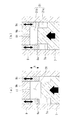
図2(a),(b)にも示すように、ピストン7の頂面には、その中央部に円柱状の凸部7aが形成されている。この凸部7aの頂部面積は、ピストン7の横断面積よりも小さい。例えば、ピストン7の直径が80ミリであるとすれば、凸部7aの直径は50ミリ程度、凸部7aの頂面からの高さは60ミリ程度を例示することができるが、この寸法、あるいはこの直径の比率に限定されるものではない。
As shown in FIGS. 2A and 2B, a columnar
一方、シリンダ9の天井面には、その中央部に円柱孔状の凹部9aが形成されている。この凹部9aの内径は、ピストン7が上昇した時に、ピストン7の凸部7aが数ミリ程度の隙間を介して挿入される寸法に設定されている。
On the other hand, a cylindrical hole-shaped
凹部9aの深さhは、ゼロから凸部7aの高さと同じ高さまでの範囲で変更することができる。例えば、シリンダ9の頂部の構造は、中心部に位置する円柱状の固定部材9bの周囲に、円筒状の可動部材9cが密に、且つ上下に相対移動可能に設けられた構造となっており、固定部材9bの下方、且つ可動部材9cの内周側の空間が凹部9aとなる。なお、油圧経路11は固定部材9bの下面に開口している。
The depth h of the
そして、図1に示すアクチュエータ17で可動部材9cを上下に移動させることで、凹部9aの深さhを変更することができる。例えば、固定部材9bの外周面と可動部材9cの内周面との間をネジ対偶とし、アクチュエータ17の動力で可動部材9cを固定部材9bに対して相対回転させることにより、可動部材9cを上下に移動させて凹部9aの深さを変更することが考えられる。なお、シリンダ9の内周面と可動部材9cの外周面との間をネジ対偶としてもよい。
And the depth h of the recessed
また、図1に示す制御装置19は、アクチュエータ17を制御して可動部材9cの上下位置を設定する。例えば、制御装置19は、ディーゼルエンジンの負荷が上がるにつれて凹部9aの深さが大きくなるようにアクチュエータ17を制御する。
Further, the
次に、上記のように構成された排気弁駆動装置1の動作について説明する。
油圧供給装置13のカム35(カム軸43)が回転すると、カムローラ41がカム35のカムプロファイルをなぞって回転しながら上下に移動し、その上下移動が接続軸39を介してプランジャ31をシリンダ33内で上下に摺動させる。
Next, the operation of the exhaust
When the cam 35 (cam shaft 43) of the hydraulic
プランジャ31がシリンダ33内で上方に摺動すると、加圧室37に充填されている作動油が加圧され、この作動油が油圧経路11を経てシリンダ9とピストン7との間の油圧室21に圧送される。この作動油の油圧により油圧室21の容積が拡張し、ピストン7が空気バネ装置15の付勢力に抗して押し下げられ、排気弁5が開かれる。排気弁5の開弁量はカム35のベース円35aからの高さによって決定される。
When the
また、カム35が下方に回動すると、プランジャ31が図示しない付勢手段によって下方に押し戻され、加圧室37および油圧室21に加わっていた油圧が低圧作動油供給経路45から供給される弱いベース油圧にまで降下する。このため、排気弁5が空気バネ装置15の付勢力により押し上げられて閉じられ、これによりピストン7が上昇して油圧室21の容積が最小になり、油圧室21の作動油が油圧経路11を経てシリンダ33の加圧室37に戻される。
Further, when the
このように、油圧供給装置13は、カム35に駆動されてシリンダ9に所定の開弁タイミングで間欠的に油圧を供給し、ピストン7を押圧して排気弁5を開弁させる。
Thus, the hydraulic
なお、プランジャ31による加圧時には、油圧室21内の作動油の少量が、オリフィス用経路25のオリフィス27から油圧経路11の外部へと排出されるようになっている。これにより、プランジャ31による加圧時に加圧室37から油圧室21に送られる油量よりも、排気弁5の閉弁時に油圧室21から加圧室37に戻される油量を少なくし、ピストン7をシリンダ9の最上部まできちんと上昇させて排気弁5を確実に閉じることができる。オリフィス27から排出された分の作動油は、プランジャ31がカム35に押圧されていない時に低圧作動油供給経路45から油圧経路11に補充される。
Note that a small amount of hydraulic oil in the
図4は、カム35のリフト量(a)と、油圧室21内の作動油圧(b)と、排気弁5のリフト量(c)との関係を示すグラフである。図4(b),(c)において、実線で示す線は、図2(a)に示す凹部9aの深さhがゼロの時の作動油圧と排気弁リフト量である。
FIG. 4 is a graph showing the relationship between the lift amount (a) of the
時刻t0にてカム35のプロファイルに従いカムリフト量が増大してプランジャ31が押し上げられ始めると、油圧室21の作動油圧がベース圧力から上昇し始める。時刻t1にてカムリフト量が最大値に達し、プランジャ31が上死点まで押し上げられ、作動油圧が最大値に達すると、時刻t2にて、油圧室21の油圧が空気バネ装置15の付勢力および筒内圧力に打ち勝ってピストン7を押し下げる。
When the cam lift amount increases according to the profile of the
これにより、排気弁5のリフト量が増大して、時刻t3にて排気弁5が全開となる。この時、ピストン7が押し下げられるに伴い、油圧室21の容積が拡張するため、油圧室21内の油圧は急激に減少するが、排気弁5を開弁させておくのに必要な油圧は維持される。このため、カム35のプロファイルに従いプランジャ31が上死点に維持されている期間は、排気弁5のリフト量も最大で維持されており、排気弁5は開弁状態を保持される。
As a result, the lift amount of the
時刻t5にてカム35のプロファイルに従いカムリフト量が減少してプランジャ31が下降し始めると、油圧室21の作動油圧も低下し始める。作動油圧が所定値を下回ると、空気バネ装置15の付勢力および筒内圧力が打ち勝ち、時刻t6からピストン7が上方へと押し上げられることによって排気弁5のリフト量が減少し始める。カム35のリフト量がゼロになってプランジャ31が下死点まで下げられると、排気弁5が時刻t7にて全閉となる。また、油圧経路11の作動油圧がベース圧力に戻る。
When the cam lift amount decreases according to the profile of the
図2(a)に示すように、シリンダ9の固定部材9bに対して可動部材9cが下げられて深さhの凹部9aが形成されている時には、排気弁5が閉じると、排気弁5と一体に動くピストン7がシリンダ9の奥に進むことによって油圧室21の容積が減少し、油圧室21内に充填されている作動油が油圧経路11から放出されて加圧室37に戻される。
As shown in FIG. 2A, when the
この時、ピストン7の凸部7aがシリンダ9の凹部9aに挿入されるまでは、油圧室21内の作動油がスムーズに油圧経路11に流れ込むため、ピストン7は比較的速い速度でシリンダ9の奥に進み、排気弁5は速い速度で閉じていく。そして、図2(b)に示すように、凸部7aが凹部9aに挿入され始めると、油圧室21が、凸部7aの周囲に形成される部屋21aと、凹部9aの内部に形成される部屋21bとに分断される。
At this time, until the
部屋21bにある作動油は、そのまま油圧経路11からスムーズに排出されるが、部屋21aに封じ込まれた作動油は、部屋21aと部屋21bとの間の狭い隙間を通って部屋21bに流れ込んでから油圧経路11より排出される。このため、作動油が隙間を通る際に伴う多大な流動抵抗によってピストン7の動きに緩衝作用(クッション作用)が働き、排気弁5の閉弁速度が低下し、排気弁5が完全に閉じるまでのタイミングが遅延される。
The hydraulic oil in the
凹部9aの深さhが小さければ、部屋21aから部屋21bに流れ込まなければならない油量が少なくなるため、ピストン7の上昇運動に緩衝作用が加わる時間が短くなる。このため、排気弁5はカム35のプロファイルによって定められた閉弁タイミングに近い、比較的速いタイミングで閉じる。
If the depth h of the
また、凹部9aの深さhが大きくなるにつれ、部屋21aから部屋21bに流れ込まなければならない油量が多くなっていくため、その排出に時間が掛かるようになり、ピストン7の上昇運動に緩衝作用が加わる時間も長くなる。このため、排気弁5はカム35のプロファイルによって定められた閉弁タイミングよりも大きく遅れたタイミングで閉じる。
Further, as the depth h of the
このように、ピストン7の上昇行程の終了間際に、ピストン7の凸部7aがシリンダ9の凹部9aに挿入されると、部屋21bに封じ込まれる作動油の流動抵抗が生じるために、油圧室21(部屋21a)内の圧力P1,P2が、図4(b)中に破線で示すように急激に上昇する。圧力P1は凹部9aの深さhが小さい時の圧力上昇率を示し、圧力P2は凹部9aの深さhが大きい時の圧力上昇率を示している。
As described above, when the
こうして油圧室21内の圧力P1,P2が急激に高まるため、図4(c)中に破線L1,L2で示すように、排気弁5が閉じる間際には、そのリフト量の減少率が緩やかな傾きとなる。排気弁5のリフト量の減少率は、油圧室21内の圧力がP1の時に破線L1で示すものとなり、油圧室21内の圧力がP2の時に破線L2で示すものとなる。つまり、凹部9aの深さhが大きくなるほど排気弁5が完全に閉じるまでの時間が長くなる(閉弁タイミングが遅くなる)。このため、排気弁5は比較的ゆっくりした速度でバルブシート(弁座)に着座し、バルブシートとの衝突による衝撃から守られる。
Thus, the pressures P1 and P2 in the
このように、シリンダ9側に設けられた凹部9aの深さを変更することにより、排気弁5が閉じるタイミングを、カム35のカムプロフィールにより規定される閉弁タイミングに近付けたり、規定の閉弁タイミングよりも遅くしたりすることができるので、ディーゼルエンジンの特性を運転状況に適合させることができる。
In this way, by changing the depth of the
また、排気弁5が閉じるタイミングの変更は、シリンダ9に設けられた凹部9aの深さを変更する、即ちシリンダ9の固定部材9bに対して可動部材9cをアクチュエータ17で軸方向に相対移動させるという簡単な構造で達成できるため、簡素な構成であることが望ましい舶用のディーゼルエンジンに適した構造とすることができる。
Further, when the timing of closing the
さらに、制御装置19は、ディーゼルエンジンの負荷が増大するにつれて凹部9aの深さhが大きくなるようにアクチュエータ17を制御する。このため、ディーゼルエンジンの負荷が高まるにつれて排気弁5が閉じるタイミングが遅くなる。これにより、高負荷運転時に筒内ガスの圧縮圧力が高くなり過ぎることを防止してディーゼルエンジンの耐久性を高めることができる。
Further, the
図3(a),(b)は、ピストン7の凸部7aとシリンダ9の凹部9aの別な形状例を示す縦断面図である。
ここでは、ピストン7の頂面に設けられている凸部7aが、ピストン7の頂面の周囲から円筒状に突出するように形成されている。一方、シリンダ9の天井面に設けられている凹部9aは、天井面の周囲に筒状の凹みとして形成される。つまり、図2(a),(b)に示す凸部7aと凹部9aの径方向の内外位置関係を逆転させたものとなっている。
FIGS. 3A and 3B are longitudinal sectional views showing another example of the shape of the
Here, the
凹部9aの深さhは、ゼロから凸部7aの高さと同じ高さまでの範囲で変更することができる。例えば、シリンダ9の頂部の中心に設けられた円柱状の可動部材9dが上下に移動できるようになっており、この可動部材9dがシリンダ9の天井面から突き出した時に、シリンダ9の内周面と可動部材9dの外周面との間に凹部9aが形成される。
The depth h of the
可動部材9dの外径は、ピストン7が上昇した時に、ピストン7の凸部7aが数ミリ程度の隙間を介して可動部材9dの周囲を取り囲む寸法に設定されている。可動部材9dは、図1に示すアクチュエータ17によって上下に駆動され、これによって凹部9aの深さhが変更される。なお、油圧経路11は可動部材9dの下面に開口している。
The outer diameter of the
図3(a)に示すように、シリンダ9の可動部材9dが下がって深さhの凹部9aが形成されている時において、排気弁5が閉じると、排気弁5と一体に動くピストン7がシリンダ9の奥に進むことによって油圧室21の容積が減少し、油圧室21内に充填されている作動油が油圧経路11から放出されて加圧室37に戻される。
As shown in FIG. 3A, when the
この時、ピストン7の凸部7aがシリンダ9の凹部9aに挿入されるまでは、油圧室21内の作動油がスムーズに油圧経路11に流れ込むため、ピストン7は比較的速い速度でシリンダ9の奥に進み、排気弁5は速い速度で閉じていく。そして、図3(b)に示すように、凸部7aが凹部9aに挿入され始めると、油圧室21が、凸部7aの内周側に形成される部屋21aと、凹部9aの内部に形成される部屋21bとに分断される。
At this time, until the
部屋21aにある作動油は、そのまま油圧経路11からスムーズに排出されるが、部屋21bに封じ込まれた作動油は、部屋21bと部屋21aとの間の狭い隙間を通って部屋21aに流れ込んでから油圧経路11より排出される。このため、作動油が隙間を通る際に伴う多大な流動抵抗によってピストン7の動きに緩衝作用(クッション作用)が働き、排気弁5の閉弁速度が低下し、排気弁5が完全に閉じるまでのタイミングが遅延される。これにより、排気弁5をバルブシートとの衝突による衝撃から守るとともに、ディーゼルエンジンの特性を運転状況に適合させることができる。
The hydraulic oil in the
この作動油の流動抵抗による緩衝作用(クッション作用)が作用する時間の長さは、図2(a),(b)の構造の場合と同様に、凹部9aの深さhが大きくなるほど長くなる。即ち、凹部9aの深さhを大きくするほど排気弁5の閉弁タイミングを遅くすることができる。
The length of time during which the buffering action (cushioning action) due to the flow resistance of the hydraulic oil acts is longer as the depth h of the
この図3(a),(b)の構成によれば、凹部9aの高さを変更する構造を、図2(a),(b)に示した構造よりも簡素にすることができる。
3A and 3B, the structure for changing the height of the
[参考実施形態]
図5は、本発明の参考実施形態に係る排気弁駆動装置を示した概略構成図である。この排気弁駆動装置51において、第1実施形態の排気弁駆動装置1と異なる点は、ピストン7の頂面の凸部およびシリンダ9の天井面の凹部が無いことと、油圧経路11の分岐点11dからリーク通路53が分岐し、その途中にリーク通路53の通路面積を変化させる可変オリフィス55(流量調整手段)が接続されていることである。その他の部分の構成および作用は第1実施形態の排気弁駆動装置1を同様であるため、各部に同一の符号を付して説明を省略する。
[ Reference embodiment]
FIG. 5 is a schematic configuration diagram illustrating an exhaust valve driving device according to a reference embodiment of the present invention. The exhaust
可変オリフィス55の絞り量は制御装置57(制御手段)によって制御される。制御装置57は、ディーゼルエンジンの負荷が上がるにつれてリーク通路53の通路面積が小さくなるように可変オリフィス55の絞り量を制御する。なお、可変オリフィス55の代わりに流量調整弁等を設けてもよい。
The throttle amount of the
この排気弁駆動装置51によれば、第1実施形態の排気弁駆動装置1と同じく、油圧供給装置13がカム35に駆動されると、所定の開弁タイミングでシリンダ9に油圧が供給され、これによりシリンダ9内部のピストン7が押圧されて排気弁5が開かれる。また、シリンダ9への油圧供給が途絶えると、空気バネ装置15の付勢力により排気弁5が閉じられる。
According to the exhaust
リーク通路53に設けられた可変オリフィス55からは、油圧供給装置13から供給される作動油(油圧)の一部が油圧経路11の外部にリークする。これにより、油圧供給装置13による加圧時にシリンダ9に圧送される油量よりも、排気弁5の閉弁時にシリンダ9から油圧供給装置13に戻される油量が少なくなる。このため、排気弁5の閉弁時にはピストン7をシリンダ9内の最上部まできちんと上昇させて排気弁5を確実に閉じることができる。
From the
可変オリフィス55を制御することにより、油圧供給装置13から供給される作動油を外部にリークさせる量を調整することができる。このリーク量を小さくすると排気弁5が閉じる速度が遅くなり、リーク量を大きくすると排気弁5が閉じる速度が速くなる。
By controlling the
このように、油圧供給装置13とシリンダ9との間の油圧経路11から分岐するリーク通路53に可変オリフィス55を設けることによって排気弁5が閉じるタイミングを早くしたり遅くしたりできるので、ディーゼルエンジンの特性を運転状況に適合させることができる。
In this way, by providing the
しかも、排気弁5が閉じるタイミングの変更は、油圧経路11にリーク通路53と可変オリフィス55とを設けるという簡単な構造で達成できるため、簡素な構成であることが望ましい舶用のディーゼルエンジンには適している。なお、リーク通路53は必ずしも油圧経路11から分岐させなくてもよく、例えばシリンダ9から分岐させてもよい。
In addition, since the change in timing of closing the
図6は、排気弁駆動装置51におけるカム35のリフト量(a)と、油圧室21内の作動油圧(b)と、排気弁5のリフト量(c)との関係を示すグラフである。基本的な動作は図4で説明した第1実施形態の排気弁駆動装置1の場合と同様であるため、重複する説明は省略する。
FIG. 6 is a graph showing the relationship between the lift amount (a) of the
リーク通路53の可変オリフィス55の絞り量が最小であると、排気弁5の閉弁時に、油圧室21内の作動油があまり多くリークせずに油圧供給装置13に戻されるため、シリンダ9内でピストン7が上昇するのに時間が掛かる。したがって、油圧室21内における作動油圧の低下状況は、図6(b)中に実線で示すように、カム35のリフト量の減少量に見合ったものとなる。また、排気弁5のリフト量の減少状況は、図6(c)中に実線で示すようになり、排気弁5が閉じられるタイミングが遅くなる。
If the throttle amount of the
そして、可変オリフィス55の絞り量が拡大されると、油圧室21内の作動油がリークする量が多くなるため、油圧室21内から油圧供給装置13に戻される作動油の量が減り、シリンダ9内でピストン7が上昇する時間が短縮される。したがって、油圧室21内における作動油圧の低下状況は、図6(b)中に破線で示すように、カム35のリフト量の減少量よりも速く低下するようになる。また、排気弁5のリフト量の減少状況は、図6(c)中に破線で示すようになり、排気弁5が閉じられるタイミングが早くなる。
When the throttle amount of the
前述のように、制御装置57は、ディーゼルエンジンの負荷が上がるにつれてリーク通路53の通路面積が小さくなるように可変オリフィス55の絞り量を制御する。このため、ディーゼルエンジンの負荷が上がるにつれて排気弁5が閉じるタイミングを遅くし、高負荷運転時に筒内ガスの圧縮圧力が高くなり過ぎることを防止してディーゼルエンジンの耐久性を高めることができる。
As described above, the
なお、変形例として、図5中に破線で示すように、油圧室21と油圧経路11との間を接続するリーク通路53aを設け、このリーク通路53aに可変オリフィス55aを設けて、排気弁5の閉弁時にピストン7が上昇する時間を調整できるようにしてもよい。
As a modification, as shown by a broken line in FIG. 5, a
以上説明したように、本発明の第1実施形態に係る排気弁駆動装置1,参考実施形態に係る排気弁駆動装置51、およびこれを備えたディーゼルエンジンによれば、舶用のディーゼルエンジンに適した簡素な構成により、排気弁5が閉じるタイミングを変更可能にし、ディーゼルエンジンの特性を運転状況に適合させ、内燃機関の信頼性および耐久性を高めるとともに、省燃費化等にも貢献することができる。
As explained above, according to the exhaust
なお、本発明は、上記実施形態の構成のみに限定されるものではなく、本発明の要旨を逸脱しない範囲内において適宜変更や改良を加えることができ、このように変更や改良を加えた実施形態も本発明の権利範囲に含まれるものとする。 It should be noted that the present invention is not limited to the configuration of the embodiment described above, and can be appropriately modified or improved within the scope not departing from the gist of the present invention. The form is also included in the scope of the right of the present invention.
1,51 排気弁駆動装置
5 排気弁
7 ピストン
7a 凸部
9 シリンダ
9a 凹部
11 油圧経路
13 油圧供給装置(油圧供給手段)
15 空気バネ装置(閉弁付勢手段)
17 アクチュエータ
19,57 制御装置(制御手段)と、
21 油圧室
31 プランジャ
35 カム
37 加圧室
53 リーク通路
55 可変オリフィス(流量調整手段)
1, 51 Exhaust
15 Air spring device (valve closing biasing means)
17
21
Claims (5)
前記ピストンが収容されるシリンダと、
前記シリンダに油圧経路を介して接続されるとともに、カムにより駆動されて前記シリンダに所定の開弁タイミングで間欠的に油圧を供給し、前記ピストンを押圧して前記排気弁を開弁させる油圧供給手段と、
前記排気弁を閉弁方向に付勢する閉弁付勢手段と、
前記ピストンの頂面に形成されて該ピストンの横断面積よりも小さな頂部面積を有する凸部と、
前記シリンダの天井面に形成されて前記ピストンの上昇時に前記凸部が隙間を介して挿入される凹部と、
前記凹部の深さを変更するアクチュエータと、
前記アクチュエータを制御する制御手段と、
を具備してなり、
前記シリンダは、中心部に位置する円柱状の第1部材と、前記第1部材の周囲に設けられ前記第1部材に対して相対移動可能である円筒状の第2部材とを有し、
前記第1部材の下面が前記第2部材の下面よりも上方に位置し、前記凹部は、前記第1部材の下方かつ前記第2部材の内周側の空間であり、
前記アクチュエータは、前記第2部材を移動することによって、前記凹部の深さを変更することを特徴とする排気弁駆動装置。 A piston provided in an exhaust valve of the internal combustion engine;
A cylinder in which the piston is housed;
A hydraulic pressure supply that is connected to the cylinder via a hydraulic path, is driven by a cam, intermittently supplies hydraulic pressure to the cylinder at a predetermined valve opening timing, and presses the piston to open the exhaust valve. Means,
Valve closing biasing means for biasing the exhaust valve in the valve closing direction;
A convex portion formed on the top surface of the piston and having a top area smaller than the cross-sectional area of the piston;
A concave portion formed on the ceiling surface of the cylinder and into which the convex portion is inserted through a gap when the piston is raised,
An actuator for changing the depth of the recess;
Control means for controlling the actuator;
Ri name comprises a,
The cylinder includes a columnar first member located in a central portion, and a cylindrical second member provided around the first member and movable relative to the first member,
The lower surface of the first member is located above the lower surface of the second member, and the recess is a space below the first member and on the inner peripheral side of the second member;
The exhaust valve driving device according to claim 1, wherein the actuator changes the depth of the recess by moving the second member .
前記ピストンが収容されるシリンダと、
前記シリンダに油圧経路を介して接続されるとともに、カムにより駆動されて前記シリンダに所定の開弁タイミングで間欠的に油圧を供給し、前記ピストンを押圧して前記排気弁を開弁させる油圧供給手段と、
前記排気弁を閉弁方向に付勢する閉弁付勢手段と、
前記ピストンの頂面に形成されて該ピストンの横断面積よりも小さな頂部面積を有する凸部と、
前記シリンダの天井面に形成されて前記ピストンの上昇時に前記凸部が隙間を介して挿入される凹部と、
前記凹部の深さを変更するアクチュエータと、
前記アクチュエータを制御する制御手段と、
を具備してなり、
前記シリンダは、中心部に位置する円柱状の第3部材を有し、
前記第3部材の下面が前記シリンダの天井面よりも下方に位置し、前記凹部は、前記シリンダの内周面と前記第3部材の外周面との間の空間であり、
前記アクチュエータは、前記第3部材を移動することによって、前記凹部の深さを変更することを特徴とする排気弁駆動装置。 A piston provided in an exhaust valve of the internal combustion engine;
A cylinder in which the piston is housed;
A hydraulic pressure supply that is connected to the cylinder via a hydraulic path, is driven by a cam, intermittently supplies hydraulic pressure to the cylinder at a predetermined valve opening timing, and presses the piston to open the exhaust valve. Means,
Valve closing biasing means for biasing the exhaust valve in the valve closing direction;
A convex portion formed on the top surface of the piston and having a top area smaller than the cross-sectional area of the piston;
A concave portion formed on the ceiling surface of the cylinder and into which the convex portion is inserted through a gap when the piston is raised,
An actuator for changing the depth of the recess;
Control means for controlling the actuator;
Ri name comprises a,
The cylinder has a third cylindrical member located in the center,
The lower surface of the third member is positioned below the ceiling surface of the cylinder, and the recess is a space between the inner peripheral surface of the cylinder and the outer peripheral surface of the third member;
The exhaust valve driving device according to claim 1, wherein the actuator changes the depth of the recess by moving the third member .
前記ピストンが収容されるシリンダと、
前記シリンダに油圧経路を介して接続されるとともに、カムにより駆動されて前記シリンダに所定の開弁タイミングで間欠的に油圧を供給し、前記ピストンを押圧して前記排気弁を開弁させる油圧供給手段と、
前記排気弁を閉弁方向に付勢する閉弁付勢手段と、
前記ピストンの頂面に形成されて該ピストンの横断面積よりも小さな頂部面積を有する凸部と、
前記シリンダの天井面に形成されて前記ピストンの上昇時に前記凸部が隙間を介して挿入される凹部と、
前記凹部の深さを変更するアクチュエータと、
前記内燃機関の負荷が上がるにつれて前記凹部の深さが大きくなるように前記アクチュエータを制御する制御手段と、
を具備してなることを特徴とする排気弁駆動装置。 A piston provided in an exhaust valve of the internal combustion engine;
A cylinder in which the piston is housed;
A hydraulic pressure supply that is connected to the cylinder via a hydraulic path, is driven by a cam, intermittently supplies hydraulic pressure to the cylinder at a predetermined valve opening timing, and presses the piston to open the exhaust valve. Means,
Valve closing biasing means for biasing the exhaust valve in the valve closing direction;
A convex portion formed on the top surface of the piston and having a top area smaller than the cross-sectional area of the piston;
A concave portion formed on the ceiling surface of the cylinder and into which the convex portion is inserted through a gap when the piston is raised,
An actuator for changing the depth of the recess;
Control means for controlling the actuator so that the depth of the recess increases as the load of the internal combustion engine increases ;
An exhaust valve driving device comprising:
Priority Applications (5)
| Application Number | Priority Date | Filing Date | Title |
|---|---|---|---|
| JP2013267798A JP6092090B2 (en) | 2013-12-25 | 2013-12-25 | Exhaust valve driving device and internal combustion engine provided with the same |
| KR1020167035103A KR20160147070A (en) | 2013-12-25 | 2014-09-26 | Exhaust valve drive device and internal combustion engine equipped with same |
| CN201480062833.9A CN105814290B (en) | 2013-12-25 | 2014-09-26 | Exhaust valve actuator and internal combustion engine with the exhaust valve actuator |
| PCT/JP2014/075754 WO2015098219A1 (en) | 2013-12-25 | 2014-09-26 | Exhaust valve drive device and internal combustion engine equipped with same |
| KR1020167011745A KR101727872B1 (en) | 2013-12-25 | 2014-09-26 | Exhaust valve drive device and internal combustion engine equipped with same |
Applications Claiming Priority (1)
| Application Number | Priority Date | Filing Date | Title |
|---|---|---|---|
| JP2013267798A JP6092090B2 (en) | 2013-12-25 | 2013-12-25 | Exhaust valve driving device and internal combustion engine provided with the same |
Related Child Applications (1)
| Application Number | Title | Priority Date | Filing Date |
|---|---|---|---|
| JP2016236128A Division JP6254245B2 (en) | 2016-12-05 | 2016-12-05 | Exhaust valve driving device and internal combustion engine provided with the same |
Publications (3)
| Publication Number | Publication Date |
|---|---|
| JP2015124631A JP2015124631A (en) | 2015-07-06 |
| JP2015124631A5 JP2015124631A5 (en) | 2016-03-03 |
| JP6092090B2 true JP6092090B2 (en) | 2017-03-08 |
Family
ID=53478099
Family Applications (1)
| Application Number | Title | Priority Date | Filing Date |
|---|---|---|---|
| JP2013267798A Active JP6092090B2 (en) | 2013-12-25 | 2013-12-25 | Exhaust valve driving device and internal combustion engine provided with the same |
Country Status (4)
| Country | Link |
|---|---|
| JP (1) | JP6092090B2 (en) |
| KR (2) | KR101727872B1 (en) |
| CN (1) | CN105814290B (en) |
| WO (1) | WO2015098219A1 (en) |
Families Citing this family (3)
| Publication number | Priority date | Publication date | Assignee | Title |
|---|---|---|---|---|
| JP6034922B1 (en) | 2015-06-22 | 2016-11-30 | 富士重工業株式会社 | Vehicle control device |
| CN106703928B (en) * | 2016-12-28 | 2022-07-15 | 沪东重机有限公司 | Exhaust valve control execution system directly driven by servo oil |
| CN108868936B (en) * | 2018-06-13 | 2020-09-08 | 中国北方发动机研究所(天津) | High-compactness hydraulic tappet of internal combustion engine |
Family Cites Families (8)
| Publication number | Priority date | Publication date | Assignee | Title |
|---|---|---|---|---|
| JPH0158740U (en) * | 1987-10-06 | 1989-04-12 | ||
| DK157145C (en) | 1987-11-05 | 1990-05-14 | Man B & W Diesel Gmbh | PROCEDURE FOR CONTROLING THE CLUTCH MOVEMENT OF A HYDRAULIC ACTIVATED EXHAUST VALVE IN A MARINE DIESEL ENGINE AND EXHAUST VALVE FOR USE IN EXERCISING THE PROCEDURE |
| JPH0726922A (en) * | 1993-07-07 | 1995-01-27 | Zexel Corp | Valve control device for internal combustion engine |
| JPH094425A (en) * | 1995-06-19 | 1997-01-07 | Nissan Motor Co Ltd | Variable valve gear for internal combustion engine |
| JP3160502B2 (en) * | 1995-09-01 | 2001-04-25 | 日鍛バルブ株式会社 | Hydraulic intake and exhaust valve drive with damper |
| JP2964235B2 (en) | 1998-03-04 | 1999-10-18 | 株式会社グリーンライフ | Planter suspension |
| JP4043136B2 (en) * | 1999-03-30 | 2008-02-06 | 三菱重工業株式会社 | Hydraulic exhaust valve drive device |
| CN103277163B (en) * | 2013-05-07 | 2015-06-24 | 宁波华液机器制造有限公司 | Variable-lift driver |
-
2013
- 2013-12-25 JP JP2013267798A patent/JP6092090B2/en active Active
-
2014
- 2014-09-26 KR KR1020167011745A patent/KR101727872B1/en active IP Right Grant
- 2014-09-26 CN CN201480062833.9A patent/CN105814290B/en not_active Expired - Fee Related
- 2014-09-26 KR KR1020167035103A patent/KR20160147070A/en active Search and Examination
- 2014-09-26 WO PCT/JP2014/075754 patent/WO2015098219A1/en active Application Filing
Also Published As
| Publication number | Publication date |
|---|---|
| CN105814290A (en) | 2016-07-27 |
| KR20160067918A (en) | 2016-06-14 |
| WO2015098219A1 (en) | 2015-07-02 |
| KR20160147070A (en) | 2016-12-21 |
| JP2015124631A (en) | 2015-07-06 |
| KR101727872B1 (en) | 2017-04-17 |
| CN105814290B (en) | 2018-11-02 |
Similar Documents
| Publication | Publication Date | Title |
|---|---|---|
| JP6137341B2 (en) | Crosshead engine | |
| JP6137342B2 (en) | engine | |
| US6752105B2 (en) | Piston-in-piston variable compression ratio engine | |
| FI124120B (en) | Steering arrangement in piston engine | |
| JP6092090B2 (en) | Exhaust valve driving device and internal combustion engine provided with the same | |
| US20090308340A1 (en) | Cam-Driven Hydraulic Lost-Motion Mechanisms for Overhead Cam and Overhead Valve Valvetrains | |
| US20100180875A1 (en) | Seating control device for a valve for a split-cycle engine | |
| JPH02264104A (en) | Valve system for internal combustion engine | |
| US9976509B2 (en) | Internal combustion engine having an engine backpressure brake and a compression release engine brake | |
| JP6254245B2 (en) | Exhaust valve driving device and internal combustion engine provided with the same | |
| JP2007513290A (en) | System and method for preventing collision between piston and valve of non-freewheel internal combustion engine | |
| JP4043136B2 (en) | Hydraulic exhaust valve drive device | |
| KR101698301B1 (en) | Exhaust-valve drive device and internal combustion engine provided with same | |
| JP6279253B2 (en) | Variable valve drive device for vehicle | |
| WO2020124554A1 (en) | Valve train and engine | |
| JP2014029138A (en) | Valve gear for internal combustion engine | |
| JP2004162664A (en) | Exhaust valve hydraulic drive unit | |
| JP6141209B2 (en) | Exhaust valve driving device and internal combustion engine provided with the same | |
| JP5463837B2 (en) | Internal combustion engine | |
| KR102169214B1 (en) | Three step variable valve timing apparatus | |
| JP2004084627A (en) | Valve mechanism | |
| KR20140126768A (en) | Hydraulic-drive fuel injection device and internal combustion engine | |
| JP2011080370A (en) | Control device for internal combustion engine | |
| ITTO20130012U1 (en) | INTERNAL COMBUSTION ENGINE WITH MODULAR TORQUE ON EACH CYLINDER |
Legal Events
| Date | Code | Title | Description |
|---|---|---|---|
| A621 | Written request for application examination |
Free format text: JAPANESE INTERMEDIATE CODE: A621 Effective date: 20160107 |
|
| A521 | Request for written amendment filed |
Free format text: JAPANESE INTERMEDIATE CODE: A523 Effective date: 20160118 |
|
| A131 | Notification of reasons for refusal |
Free format text: JAPANESE INTERMEDIATE CODE: A131 Effective date: 20161004 |
|
| A521 | Request for written amendment filed |
Free format text: JAPANESE INTERMEDIATE CODE: A523 Effective date: 20161205 |
|
| TRDD | Decision of grant or rejection written | ||
| A01 | Written decision to grant a patent or to grant a registration (utility model) |
Free format text: JAPANESE INTERMEDIATE CODE: A01 Effective date: 20170110 |
|
| A61 | First payment of annual fees (during grant procedure) |
Free format text: JAPANESE INTERMEDIATE CODE: A61 Effective date: 20170208 |
|
| R150 | Certificate of patent or registration of utility model |
Ref document number: 6092090 Country of ref document: JP Free format text: JAPANESE INTERMEDIATE CODE: R150 |
|
| S111 | Request for change of ownership or part of ownership |
Free format text: JAPANESE INTERMEDIATE CODE: R313114 |
|
| R350 | Written notification of registration of transfer |
Free format text: JAPANESE INTERMEDIATE CODE: R350 |
|
| R250 | Receipt of annual fees |
Free format text: JAPANESE INTERMEDIATE CODE: R250 |
|
| R250 | Receipt of annual fees |
Free format text: JAPANESE INTERMEDIATE CODE: R250 |
|
| R250 | Receipt of annual fees |
Free format text: JAPANESE INTERMEDIATE CODE: R250 |