JP6091908B2 - Terminal device and display program - Google Patents
Terminal device and display program Download PDFInfo
- Publication number
- JP6091908B2 JP6091908B2 JP2013010495A JP2013010495A JP6091908B2 JP 6091908 B2 JP6091908 B2 JP 6091908B2 JP 2013010495 A JP2013010495 A JP 2013010495A JP 2013010495 A JP2013010495 A JP 2013010495A JP 6091908 B2 JP6091908 B2 JP 6091908B2
- Authority
- JP
- Japan
- Prior art keywords
- panel
- display
- target area
- frame
- screen
- Prior art date
- Legal status (The legal status is an assumption and is not a legal conclusion. Google has not performed a legal analysis and makes no representation as to the accuracy of the status listed.)
- Active
Links
- 238000000034 method Methods 0.000 claims description 48
- 238000001514 detection method Methods 0.000 claims description 33
- 238000010586 diagram Methods 0.000 description 15
- 230000006870 function Effects 0.000 description 9
- 238000012545 processing Methods 0.000 description 9
- 230000009466 transformation Effects 0.000 description 8
- 230000004048 modification Effects 0.000 description 7
- 238000012986 modification Methods 0.000 description 7
- 230000008859 change Effects 0.000 description 6
- 230000005540 biological transmission Effects 0.000 description 4
- 238000004891 communication Methods 0.000 description 4
- 230000008569 process Effects 0.000 description 2
- 230000001131 transforming effect Effects 0.000 description 2
- 125000002066 L-histidyl group Chemical group [H]N1C([H])=NC(C([H])([H])[C@](C(=O)[*])([H])N([H])[H])=C1[H] 0.000 description 1
- 230000008901 benefit Effects 0.000 description 1
- 230000007423 decrease Effects 0.000 description 1
- 230000002093 peripheral effect Effects 0.000 description 1
- 238000000926 separation method Methods 0.000 description 1
- 230000000007 visual effect Effects 0.000 description 1
Images
Landscapes
- User Interface Of Digital Computer (AREA)
Description
本発明は、端末装置及び表示プログラムに関する。 The present invention relates to a terminal device and a display program.
表示画面に定められた領域毎にアイコン画像を表示する電子装置(端末装置)が、特許文献1に開示されている。
An electronic device (terminal device) that displays an icon image for each region defined on a display screen is disclosed in
端末装置では、表示画面に情報を表示するに際して、ユーザに対して視覚的に心地良さや視認性を与えることが望まれている。 In a terminal device, when displaying information on a display screen, it is desired to visually give comfort and visibility to a user.
本発明は、前記の点に鑑みてなされたものであり、表示画面に情報を表示するに際して、ユーザに対して視覚的に心地良さや視認性を与えることができる端末装置及び表示プログラムを提供することを目的とする。 The present invention has been made in view of the above points, and provides a terminal device and a display program that can visually give comfort and visibility to a user when displaying information on a display screen. For the purpose.
(1)上記の課題を解決するために、本発明に係る端末装置は、画面が格子状に区切られた複数の格子領域から構成され、前記格子領域を単位として1個以上の前記格子領域からなる対象領域毎に情報を表示する表示部と、前記対象領域に対する操作を検出する検出部と、前記検出部により操作が検出された前記対象領域を、前記操作が為された位置に応じて変形させて、前記表示部の画面に表示するように制御する制御部と、を備え、前記制御部は、前記操作が為された位置と前記対象領域の枠との間に働く所定の力が発生するとみなして、前記検出部により操作が検出された前記対象領域の変形後の形状を計算する、ことを特徴とする。 (1) In order to solve the above-described problem, a terminal device according to the present invention includes a plurality of lattice regions in which a screen is partitioned in a lattice shape, and includes one or more lattice regions in units of the lattice region. A display unit that displays information for each target region, a detection unit that detects an operation on the target region, and the target region where an operation is detected by the detection unit, depending on a position where the operation is performed And a control unit that controls to display on the screen of the display unit, and the control unit generates a predetermined force that acts between the position where the operation is performed and the frame of the target area. Accordingly, the shape after deformation of the target region whose operation is detected by the detection unit is calculated .
(2)上記の課題を解決するために、本発明に係る端末装置は、画面が格子状に区切られた複数の格子領域から構成され、前記格子領域を単位として1個以上の前記格子領域からなる対象領域毎に情報を表示する表示部と、前記対象領域に対する操作を検出する検出部と、前記検出部により操作が非検出である前記対象領域を、あらかじめ定められた操作が為されたとみなして変形させて、前記表示部の画面に表示するように制御する制御部と、を備え、前記制御部は、前記操作が為されたとみなされる位置と前記対象領域の枠との間に働く所定の力が発生するとみなして、前記検出部により操作が非検出である前記対象領域の変形後の形状を計算する、ことを特徴とする。 ( 2 ) In order to solve the above-described problem, a terminal device according to the present invention includes a plurality of lattice regions in which a screen is partitioned in a lattice shape, and includes one or more lattice regions in units of the lattice region. A display unit that displays information for each target region, a detection unit that detects an operation on the target region, and the target region in which an operation is not detected by the detection unit is regarded as having been performed in advance. And a control unit that controls the display unit to display it on the screen of the display unit, and the control unit is configured to operate between a position where the operation is considered to be performed and a frame of the target area. It is assumed that the force is generated, and the shape after deformation of the target region whose operation is not detected by the detection unit is calculated .
(3)上記の課題を解決するために、本発明に係る端末装置は、画面に長方形の対象領域毎に情報を表示する表示部と、前記対象領域に対する操作を検出する検出部と、前記検出部により操作が検出された前記対象領域を、前記操作が為された位置に応じて変形させるとともに、前記対象領域に対応する情報の表示態様を変化させて、前記表示部の画面に表示するように制御する制御部と、を備え、前記制御部は、前記操作が為された位置と前記対象領域の枠との間に働く所定の力が発生するとみなして、前記検出部により操作が検出された前記対象領域の変形後の形状を計算する、ことを特徴とする。 ( 3 ) In order to solve the above-described problem, a terminal device according to the present invention includes a display unit that displays information for each rectangular target region on a screen, a detection unit that detects an operation on the target region, and the detection The target area where the operation is detected by the unit is deformed according to the position where the operation is performed, and the display mode of the information corresponding to the target area is changed and displayed on the screen of the display unit A control unit that controls the operation, and the control unit detects that a predetermined force acting between the position where the operation is performed and a frame of the target area is generated, and the operation is detected by the detection unit. The shape after deformation of the target area is calculated .
(4)上記の課題を解決するために、本発明に係る表示プログラムは、コンピュータに、画面が格子状に区切られた複数の格子領域の当該格子領域を単位として1個以上の前記格子領域からなる対象領域毎に情報を表示する手順と、前記対象領域に対する操作を検出する手順と、前記操作が検出された前記対象領域を、前記操作が為された位置に応じて変形させて、前記画面に表示するように制御する手順と、を実行させるためのプログラムであって、前記操作が為された位置と前記対象領域の枠との間に働く所定の力が発生するとみなして、前記操作が検出された前記対象領域の変形後の形状を計算する、プログラムである。 ( 4 ) In order to solve the above-described problem, a display program according to the present invention causes a computer to read from one or more lattice areas in units of the lattice areas of a plurality of lattice areas in which a screen is partitioned in a lattice shape. A procedure for displaying information for each target area, a procedure for detecting an operation on the target area, and the target area where the operation is detected is deformed according to a position where the operation is performed, and the screen And a procedure for controlling the display so that a predetermined force acting between the position where the operation is performed and the frame of the target area is generated. It is a program for calculating a shape after deformation of the detected target area .
(5)上記の課題を解決するために、本発明に係る表示プログラムは、コンピュータに、画面が格子状に区切られた複数の格子領域の当該格子領域を単位として1個以上の前記格子領域からなる対象領域毎に情報を表示する手順と、前記対象領域に対する操作を検出する手順と、前記操作が非検出である前記対象領域を、あらかじめ定められた操作が為されたとみなして変形させて、前記画面に表示するように制御する手順と、を実行させるためのプログラムであって、前記操作が為されたとみなされる位置と前記対象領域の枠との間に働く所定の力が発生するとみなして、前記操作が非検出である前記対象領域の変形後の形状を計算する、プログラムである。 ( 5 ) In order to solve the above-described problem, a display program according to the present invention causes a computer to read from one or more lattice regions in units of the lattice regions of a plurality of lattice regions in which a screen is partitioned in a lattice shape. A procedure for displaying information for each target area, a procedure for detecting an operation on the target area, and transforming the target area in which the operation is not detected, assuming that a predetermined operation has been performed, A program for performing control to display on the screen, assuming that a predetermined force is generated between a position where the operation is considered to be performed and a frame of the target area. A program for calculating a deformed shape of the target area in which the operation is not detected .
(6)上記の課題を解決するために、本発明に係る表示プログラムは、コンピュータに、画面に長方形の対象領域毎に情報を表示する手順と、前記対象領域に対する操作を検出する手順と、前記操作が検出された前記対象領域を、前記操作が為された位置に応じて変形させるとともに、前記対象領域に対応する情報の表示態様を変化させて、前記画面に表示するように制御する手順と、を実行させるためのプログラムであって、前記操作が為された位置と前記対象領域の枠との間に働く所定の力が発生するとみなして、前記操作が検出された前記対象領域の変形後の形状を計算する、プログラムである。 ( 6 ) In order to solve the above-described problem, a display program according to the present invention provides a computer with a procedure for displaying information for each rectangular target area on a screen, a procedure for detecting an operation on the target area, A procedure for controlling the target area where the operation is detected to be deformed according to the position where the operation is performed and changing the display mode of the information corresponding to the target area to display the information on the screen; , After the deformation of the target area where the operation is detected, assuming that a predetermined force is generated between the position where the operation is performed and the frame of the target area. Is a program that calculates the shape of
本発明によれば、表示画面に情報を表示するに際して、ユーザに対して視覚的に心地良さや視認性を与えることができる。 ADVANTAGE OF THE INVENTION According to this invention, when displaying information on a display screen, visual comfort and visibility can be given with respect to a user.
本発明の一実施形態について図面を参照して詳細に説明する。
[第1実施形態]
<端末装置の構成例>
図1は、本発明の一実施形態に係る端末装置100が有する表示部150の画面(表示画面)の外観の概略の一例を示す図である。
本実施形態に係る端末装置100の表示画面は、横方向よりも縦方向が長い長方形を有している。そして、表示画面が、複数の格子領域に分割されて構成されている。表示画面において、複数の格子領域は、縦方向にn個及び横方向にm個(n、mは、それぞれ、1以上の整数であり、且つ、いずれか一方は2以上である。)の格子領域から構成されている。本実施形態では、n=5であり、m=3であり、表示画面は計15個の格子領域から構成されている。本実施形態では、各格子領域は正方形である。
An embodiment of the present invention will be described in detail with reference to the drawings.
[First Embodiment]
<Configuration example of terminal device>
FIG. 1 is a diagram illustrating an example of a schematic external appearance of a screen (display screen) of a
The display screen of the
本実施形態では、表示画面には、当該表示画面に向かって最も左上の格子を原点(0,0)とする格子単位のNM座標(N,M)=(0〜4,0〜2)として、向かって下向きのN軸と、向かって右向きのM軸と、が定められているとして説明する。
表示画面には、隣接する1以上の整数個の格子領域を有する領域(パネル)10〜14、20〜24、30、31、34が表示される。
図1の例では、パネル10〜14、20〜22、24、30、34は、それぞれ、1個の格子領域から構成されている。パネル23は、横に並ぶ2個の格子領域から構成されている。パネル31は、縦に並ぶ2個の格子領域から構成されている。また、端末装置100は、表示画面に、他の任意の複数の格子領域を組み合わせたパネルを表示することが可能である。
In the present embodiment, the display screen has the grid unit NM coordinates (N, M) = (0, 4, 0 to 2) with the upper left grid facing the display screen as the origin (0, 0). A description will be given assuming that a downward N-axis and a right-facing M-axis are defined.
On the display screen, areas (panels) 10 to 14, 20 to 24, 30, 31, 34 having one or more adjacent lattice areas are displayed.
In the example of FIG. 1, the
また、各パネル10〜14、20〜24、30、31、34には、アプリケーション自体を示すアイコンの画像や、アプリケーションにより表示される情報(例えば、文字、写真など)の画像が設定されて表示される。このような設定は、例えば、ユーザの操作により指定されて行われてもよく、或いは、端末装置100により自動的に行われてもよい。
図1の例では、パネル10には現在時刻を示すアナログ時計の画像が表示されており、パネル23にはメール等の文字列(“Hello!!”)の画像が表示されており、パネル34には穴埋め画像が表示されている。また、他のパネル11〜14、20〜22、24、30、31にも、それぞれ、様々な画像が表示される(図1では、図示を省略している。)。
Each
In the example of FIG. 1, an image of an analog clock indicating the current time is displayed on the
また、本実施形態では、表示画面は、格子領域の単位(格子単位)よりも更に細かい複数の画素から構成されている。本実施形態では、表示画面には、当該表示画面に向かって最も左上の点を原点(0,0)とする画素単位のXY座標(X,Y)=(0〜XM,0〜YM)として、向かって下向きのX軸と、向かって右向きのY軸と、が定められているとして説明する。ここで、XM及びYMは、それぞれ、X軸方向の最大の座標値及びY軸方向の最大の座標値であり、図1の例では、XM:YM=5:3である。本実施形態では、1個の格子領域について、X軸方向の画素数とY軸方向の画素数は同じ数であり、例えば、数百である。 In the present embodiment, the display screen is composed of a plurality of pixels that are finer than the unit of the lattice area (lattice unit). In the present embodiment, the display screen has XY coordinates (X, Y) = (0 to XM, 0 to YM) in pixel units with the upper left point facing the display screen as the origin (0, 0). In the following description, it is assumed that a downward X axis and a right Y axis are defined. Here, XM and YM are the maximum coordinate value in the X-axis direction and the maximum coordinate value in the Y-axis direction, respectively, and in the example of FIG. 1, XM: YM = 5: 3. In the present embodiment, the number of pixels in the X-axis direction and the number of pixels in the Y-axis direction are the same for one lattice region, for example, several hundred.
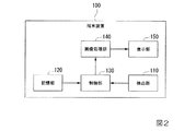
図2は、本発明の一実施形態に係る端末装置100の概略的な機能の構成例を示すブロック図である。
端末装置100は、検出部110と、記憶部120と、制御部130と、画像処理部140と、表示部150を備える。
本実施形態では、ユーザは、端末装置100の表示部150の表示画面に表示されているパネル10〜14、20〜24、30、31、34に対する操作を、その表示画面に指で触れる(タッチする)ことにより行う。
FIG. 2 is a block diagram illustrating a schematic functional configuration example of the
The
In the present embodiment, the user touches the display screen with his / her finger on the operation on the
検出部110は、表示部150の表示画面を透明な部材で覆うように備えられる。検出部110は、表示画面に格子状に定められた格子領域から構成されるパネル10〜14、20〜24、30、31、34に対する操作を、例えば、ユーザの指と表示画面との接触(タッチ)に基づいて検出する。
検出部110は、表示画面においてユーザにより操作された位置を示す情報を、制御部130に出力する。ここで、操作された位置を示す情報は、例えば、表示部150の表示画面に定められたXY座標(X,Y)で表現される。
The
The
記憶部120は、制御部130を動作させるためのプログラムや、各種の情報を記憶する。例えば、記憶部120は、各パネル10〜14、20〜24、30、31、34に表示される画像の情報を記憶する。
制御部130は、各種の制御や処理を実行する。例えば、制御部130は、検出部110から入力される情報(表示画面においてユーザにより操作された位置)に基づいて、それに対応する処理を実行する。制御部130は、例えば、中央演算処理装置(CPU:Central Processing Unit)である。制御部130は、例えば、記憶部120に記憶されたプログラムに基づいて動作する。制御部130は、例えば、画像処理部140を制御して、表示部150の表示画面に表示される情報を制御する。
The
The
画像処理部140は、制御部130による制御に基づいて,各種の画像(例えば、アイコンの画像、時刻を示す画像、文字列を示す画像、穴埋め画像、写真の画像など)を生成する。画像処理部140は、生成した画像を示す情報を、表示画面に定められたパネル10〜14、20〜24、30、31、34毎に、表示部150に出力する。
表示部150は、画像処理部140により生成された画像を、表示画面に定められたパネル10〜14、20〜24、30、31、34毎に、当該表示画面に表示する。
The
The
<パネルの構成例>
図3は、本発明の一実施形態に係る1個の格子領域から構成されるパネル201の構成例を示す図である。
正方形のパネル201の枠は、複数の点211(図3では、1個の点のみに符号を付してある)から構成されており、これら複数の点211を結んで構成される。
各点211は、例えば、画素位置(X,Y)の点と一致する。また、例えば、枠上に存在する全ての画素位置の点を用いてパネル201の枠が構成されてもよく、或いは、枠上に存在する全ての画素位置の点ではなく、所定間隔などの一部の画素位置の点を用いてパネル201の枠が構成されてもよい。
ここで、図3の例では、1個の格子領域から構成されるパネル201の構成例を示したが、2個以上の格子領域から構成されるパネルの構成例についても、同様である。
<Example of panel configuration>
FIG. 3 is a diagram illustrating a configuration example of the
The frame of the
Each
Here, in the example of FIG. 3, the configuration example of the
<パネルがユーザにより押下された場合の表示>
本実施形態では、画面のスクロールは行われておらず、スクロールは停止した状態であるとする。
他の例として、画面がスクロール中である場合には、例えば、画面がスクロール中である場合における表示態様(例えば、あらかじめ定められたもの)に従って表示画面の表示情報が制御される。なお、例えば、画面がスクロール中である場合に、本実施形態に係る表示態様が採用されてもよく、或いは、本実施形態に係る表示態様と他の表示態様とが組み合わされて用いられてもよい。
<Display when the panel is pressed by the user>
In this embodiment, it is assumed that the screen is not scrolled and the scrolling is stopped.
As another example, when the screen is being scrolled, for example, display information on the display screen is controlled according to a display mode (for example, predetermined one) when the screen is being scrolled. For example, when the screen is being scrolled, the display mode according to the present embodiment may be adopted, or the display mode according to the present embodiment may be used in combination with another display mode. Good.
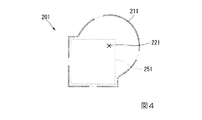
図4は、本実施形態に係るパネル201がユーザにより押下された場合におけるパネル201の変形の概略の一例を示す図である。
図4には、表示画面上において、パネル201の枠に対して、枠内に存在する点(押下の点)221がユーザの指により押下された場合に、制御部130が当該押下の点221に基づいて制御を行うことにより表示画面に表示されるパネル201の枠の形状の一例(パネル201の変形の一例)を示してある。また、図4には、参考として、変形前におけるパネル201の形状(元のパネル形状)251も示してあるが、これは実際には表示画面には表示されない。
図4の例では、変形後におけるパネル201の枠は、変形後における複数の点211(図4では、1個の点のみに符号を付してある)から構成され、これら変形後における複数の点211を結んで構成される。
FIG. 4 is a diagram illustrating an example of an outline of deformation of the
In FIG. 4, when the point (pressed point) 221 existing in the frame is pressed by the user's finger with respect to the frame of the
In the example of FIG. 4, the frame of the
本実施形態におけるパネル201の枠の変形の方法を説明する。
本実施形態では、パネル201の枠を構成する各点211に磁石の所定の大きさAを有するS極が存在するとみなす。
また、押下の点221が押下されたときに、当該押下の点221に磁石の所定の大きさBを有するS極が発生するとみなす。
そして、パネル201の枠を構成する各点211に、当該各点211のS極と押下の点221のS極とによる磁石の力(反発力)が発生するとして、各点211の位置を時間の流れに応じて変化させる。
A method for deforming the frame of the
In the present embodiment, it is assumed that an S pole having a predetermined size A of the magnet exists at each
Further, when the pressed
Then, at each
ここで、本実施形態では、S極とS極との反発力を用いて説明するが、他の例として、N極とN極との反発力を用いてもよく、同様である。
また、パネル201の枠を構成する各点211のS極の大きさAと、押下の点221のS極の大きさBとしては、それぞれ、任意の値が用いられてもよく、例えば、同じ値が用いられてもよく、或いは、異なる値が用いられてもよい。
また、本実施形態では、磁石の力を用いて説明するが、任意の力が用いられてもよい。例えば、距離(距離の1乗)に反比例する関数で表される力、又は、距離のp(pは2以上の整数)乗に反比例する関数で表される力、又は、距離の任意のべき乗の項を任意の種類だけ有する関数で表される力などを用いることができる。
本実施形態では、この距離として、パネル201の枠を構成する各点211と押下の点221との間の距離を用いる。
Here, although this embodiment demonstrates using the repulsive force of a south pole and a south pole, as another example, you may use the repulsive force of a north pole and a north pole, and it is the same.
Also, any value may be used as the magnitude A of the south pole of each
Moreover, although this embodiment demonstrates using the force of a magnet, arbitrary forces may be used. For example, a force represented by a function inversely proportional to the distance (the first power of the distance), a force represented by a function inversely proportional to the power of the distance p (p is an integer of 2 or more), or an arbitrary power of the distance A force represented by a function having an arbitrary type of the term can be used.
In the present embodiment, the distance between each
また、押下の点221に発生するS極の大きさB(又は、それによって発生する力など)には、その発生から時間が経つに従ってその大きさを小さくするための係数(減衰係数)が乗算される。この係数は、時間に対して連続的な関数であってもよく、又は、時間に対して段階的に変化する値であってもよく、例えば、時間が経つに従って絶対値が小さくなる正の値である。この係数は、所定の時間を超えた場合に0(ゼロ)になる値であってもよく、又は、ゼロにはならないが時間が経過するに従って、計算上の丸め込みなどにより、実質的に0(ゼロ)になるような値であってもよい。
なお、本実施形態では、ユーザにより同じ点(押下の点)が押下され続けると、パネル201の枠が同じ変形状態で維持され続ける態様を用いており、つまり、ユーザにより同じ点(押下の点)が押下され続ける場合には、減衰係数を用いない。つまり、本実施形態では、ユーザにより同じ点が押下され続けると、その押下に応じた力が発生し続ける(減衰係数に関する時間が経過しない)とみなす。
Further, the magnitude B of the south pole generated at the pressed point 221 (or the force generated thereby) is multiplied by a coefficient (attenuation coefficient) for reducing the magnitude as time passes from the generation. Is done. This coefficient may be a continuous function with respect to time, or may be a value that changes stepwise with respect to time, for example, a positive value that decreases in absolute value over time. It is. This coefficient may be a value that becomes 0 (zero) when a predetermined time is exceeded, or is not substantially zero, but is substantially 0 ( The value may be zero).
In the present embodiment, when the same point (pressed point) is continuously pressed by the user, the frame of the
また、パネル201の枠を構成する各点211には、更に、当該各点211が変形前の各点の位置(元の位置)に戻ろうとする力が常に働いているとみなして、各点211の位置を時間の流れに応じて変化させる。一例として、各点211には、各点の元の位置からの離隔距離(又は、そのべき乗など)に比例する引力が常に働くとみなす。
Further, it is assumed that each
制御部130は、表示画面上でパネル201がユーザにより押下された場合には、上記した押下の点221に応じた反発力や、元の位置に戻ろうとする引力が働くとみなして、パネル201の枠を構成する各点211の位置を時間の流れに応じて計算して、その計算結果に応じた位置に変形後における各点211を表示させ、これにより、変形後におけるパネル201を表示させる。
When the
ここで、パネル201の枠を構成する各点211の位置の変化を計算するために必要な他の値(例えば、各点211の質量など)があれば、任意に設定されてもよい。
また、例えば、ユーザがパネル201の枠内の位置を当該ユーザの指で触れたまま、その指を上下左右に動かすと、押下の点221の位置がずれて、それに応じたS極の位置もずれる。制御部130は、このような押下の点221の位置のずれ(S極の位置のずれ)に従って、パネル201の枠を構成する各点211の位置の変化を計算する。
また、同じパネル201の枠内がユーザにより異なるタイミングで複数回押下された場合には、制御部130は、それぞれの押下によって発生する力の足し合わせ(合成)が発生するとみなして、パネル201の枠を構成する各点211の位置の変化を計算する。
Here, any other value (for example, the mass of each point 211) necessary for calculating the change in the position of each
Also, for example, if the user moves the finger up, down, left, or right while touching the position in the frame of the
In addition, when the inside of the
図4の例では、正方形のパネル201の枠内における右方の上方の端の付近の位置(押下の点221の位置)がユーザにより押下されており、パネル201の枠を構成する複数の点(例えば、数百個の点)の中で、特に、右上の端の付近(押下の部分の周辺)の点が拡張するように、パネル201の枠が変形している。
図4の例では、1個のパネル201の中で、ユーザの指で触れた部分の付近の変形が他の部分の変形とは異なるようになっており、例えば、ユーザの指で触れた部分の付近が特に膨張(拡張)するように表示される。
In the example of FIG. 4, the position near the upper right end (position of the pressing point 221) in the frame of the
In the example of FIG. 4, the deformation in the vicinity of the part touched by the user's finger in one
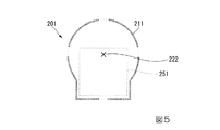
図5は、本実施形態に係るパネル201がユーザにより押下された場合におけるパネル201の変形の概略の一例を示す図である。
図5には、表示画面上において、パネル201の枠に対して、枠内に存在する点(押下の点)222がユーザの指により押下された場合に、制御部130が当該押下の点222に基づいて制御を行うことにより表示画面に表示されるパネル201の枠の形状の一例(パネル201の変形の一例)を示してある。また、図5には、参考として、変形前におけるパネル201の形状(元のパネル形状)251も示してあるが、これは実際には表示画面には表示されない。
図5の例では、変形後におけるパネル201の枠は、変形後における複数の点211(図5では、1個の点のみに符号を付してある)から構成され、これら変形後における複数の点211を結んで構成される。
FIG. 5 is a diagram illustrating an example of an outline of deformation of the
In FIG. 5, when the point (pressed point) 222 existing in the frame is pressed by the user's finger with respect to the frame of the
In the example of FIG. 5, the frame of the
本実施形態におけるパネル201の枠の変形の方法は、図4の例の場合と同様である。
図5の例では、正方形のパネル201の枠内における中央の上方の端の付近の位置(押下の点222の位置)がユーザにより押下されており、パネル201の枠を構成する複数の点(例えば、数百個の点)の中で、特に、中央の上の端の付近(押下の部分の周辺)の点が拡張するように、パネル201の枠が変形している。
The method of deforming the frame of the
In the example of FIG. 5, the position near the upper upper end in the frame of the square panel 201 (the position of the pressing point 222) has been pressed by the user, and a plurality of points ( For example, among the hundreds of points), the frame of the
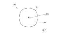
図6は、本実施形態に係るパネル201がユーザにより押下された場合におけるパネル201の変形の概略の一例を示す図である。
図6には、表示画面上において、パネル201の枠に対して、枠内に存在する点(押下の点)223がユーザの指により押下された場合に、制御部130が当該押下の点223に基づいて制御を行うことにより表示画面に表示されるパネル201の枠の形状の一例(パネル201の変形の一例)を示してある。また、図6には、参考として、変形前におけるパネル201の形状(元のパネル形状)251も示してあるが、これは実際には表示画面には表示されない。
図6の例では、変形後におけるパネル201の枠は、変形後における複数の点211(図6では、1個の点のみに符号を付してある)から構成され、これら変形後における複数の点211を結んで構成される。
FIG. 6 is a diagram illustrating an example of an outline of deformation of the
In FIG. 6, when the point (pressed point) 223 existing in the frame is pressed by the user's finger with respect to the frame of the
In the example of FIG. 6, the frame of the
本実施形態におけるパネル201の枠の変形の方法は、図4の例の場合と同様である。
図6の例では、正方形のパネル201の枠内における中心の位置(押下の点223の位置)がユーザにより押下されており、パネル201の枠を構成する複数の点(例えば、数百個の点)が、中心(押下の部分)から均等に外側の方向へ拡張するように、パネル201の枠が変形している。
The method of deforming the frame of the
In the example of FIG. 6, the center position (the position of the pressing point 223) within the frame of the
以上のように、本実施形態に係る端末装置100によると、パネル201がユーザにより押下された場合における当該パネル201の表示を制御することで、表示画面に情報(本実施形態では、パネル201の情報)を表示するに際して、ユーザに対して視覚的に心地良さや視認性を与えることができる。これにより、例えば、ユーザに操作時の心地良さを与えることができ、また、視認性を向上させて、誤操作を低減することができる。
As described above, according to the
なお、本実施形態では、パネル201の形状を変形させる方法について説明したが、例えば、パネル201自体又はパネル201に設定された画像に関する色を変化させる方法が併用されてもよい。一例として、制御部130は、パネル201に対するユーザによる押下がある状態においては、押下がない状態と比べて、パネル201自体又はパネル201に設定された画像に関する所定の色を異ならせる制御を行うことができる。
In the present embodiment, the method of changing the shape of the
[第2実施形態]
本実施形態では、第1実施形態とは異なる部分について詳しく説明し、同様な部分については詳しい説明を省略する。
[Second Embodiment]
In the present embodiment, portions different from those in the first embodiment will be described in detail, and detailed descriptions of similar portions will be omitted.
<ユーザによる操作がない場合におけるパネルの表示>
本実施形態では、画面のスクロールは行われておらず、スクロールは停止した状態であるとする。
他の例として、画面がスクロール中である場合には、例えば、画面がスクロール中である場合における表示態様(例えば、あらかじめ定められたもの)に従って表示画面の表示情報が制御される。なお、例えば、画面がスクロール中である場合に、本実施形態に係る表示態様が採用されてもよく、或いは、本実施形態に係る表示態様と他の表示態様とが組み合わされて用いられてもよい。
<Display of panel when there is no operation by the user>
In this embodiment, it is assumed that the screen is not scrolled and the scrolling is stopped.
As another example, when the screen is being scrolled, for example, display information on the display screen is controlled according to a display mode (for example, predetermined one) when the screen is being scrolled. For example, when the screen is being scrolled, the display mode according to the present embodiment may be adopted, or the display mode according to the present embodiment may be used in combination with another display mode. Good.
図7は、本実施形態に係るユーザによる操作がない場合におけるパネル201の変形の一例を説明するための図である。
図7には、パネル201の枠を構成する複数の点211を示してある。また、図7には、参考として、疑似的な指押下の範囲301も示してあるが、これは実際には表示画面には表示されない。
FIG. 7 is a diagram for explaining an example of the deformation of the
FIG. 7 shows a plurality of
本実施形態では、パネル201に対するユーザの操作がないときには、制御部130は、あらかじめ定められた疑似的な指押下の範囲301の内側に、疑似的にユーザの指が所定の時間間隔で所定の位置に触れた(タッチした)とみなして、パネル201の枠を構成する各点211の位置を時間の流れに応じて計算して、その計算結果に応じた位置に変形後における各点211を表示させ、これにより、変形後におけるパネル201を表示させる。
パネル201の枠を構成する各点211の位置を変化させる方法としては、第1実施形態で説明した方法(図4〜図6における、押下の点に応じて、枠を構成する各点の位置を変化させる方法)と同じ方法を用いる。
In the present embodiment, when there is no user operation on the
As a method of changing the position of each
ここで、疑似的な指押下の範囲301としては、様々な範囲が設定されてもよく、一例として、元のパネル形状における枠内の端の方を含まない範囲、つまり比較的中心に近い範囲を用いることができ、この場合、比較的中心に近い位置が疑似的に押下される状況を作り出すことができる。図7の例では、元のパネル形状の中心と同じ中心を持ち、元のパネル形状(図7の例では、正方形)に相似する、元より小さい形状の範囲を、疑似的な指押下の範囲301として用いている。
Here, various ranges may be set as the pseudo
また、疑似的にユーザの指が所定の時間間隔で所定の位置に触れるという条件における所定の時間間隔としては、任意の時間間隔が設定されてもよく、例えば、一定の時間間隔であってもよく、又は、変動(変化)する時間間隔であってもよい。
また、疑似的にユーザの指が所定の時間間隔で所定の位置に触れるという条件における所定の位置としては、任意の位置が用いられてもよく、例えば、一定の位置であってもよく、又は、変動(変化)する位置であってもよい。
In addition, an arbitrary time interval may be set as the predetermined time interval under the condition that the user's finger is pseudo-touched at a predetermined position at a predetermined time interval. It may also be a time interval that varies (changes).
In addition, as the predetermined position under the condition that the user's finger touches the predetermined position at predetermined time intervals in an artificial manner, an arbitrary position may be used, for example, a predetermined position may be used, or The position may be changed (changed).
例えば、疑似的な指押下の範囲301、疑似的にユーザの指が所定の時間間隔で所定の位置に触れるという条件における所定の時間間隔、当該条件における所定の位置のうちの1つ以上について、ランダムな値を用いることもできる。この場合、ランダムな値は、例えば、疑似乱数を用いて取得することが可能である。
また、表示画面上に複数の異なるパネル(図1の例では、パネル10〜14、20〜24、30、31、34)が同時に表示される場合には、制御部130は、例えば、全てのパネルのそれぞれについて、同じ態様でパネルの枠を変形させて表示するように制御することができ、又は、全てのパネルのそれぞれについて、それぞれの態様(異なり得る態様)でパネルの枠を変形させて表示するように制御することができる。
For example, for one or more of a pseudo
When a plurality of different panels (
一例として、図7に示されるパネル201について、疑似的な指押下の範囲301の内側において、疑似的にユーザの指で、毎秒に所定の複数回、ランダムな位置を触れる(押下する)とみなして、制御部130がパネル201の枠を構成する各点211の位置を変化させるように制御する。これにより、パネル201の枠を構成する各点211が(例えば、従来は静止状態であったのが)ランダムに小さい範囲で動き、このような動きは非対称になるが、人間の目で見ると時間的に平均化されて見える。
As an example, regarding the
以上のように、本実施形態に係る端末装置100によると、ユーザによる操作がない場合におけるパネル201の表示を制御することで、表示画面に情報(本実施形態では、パネル201の情報)を表示するに際して、ユーザに対して視覚的に心地良さや視認性を与えることができる。これにより、例えば、ユーザに無操作時の心地良さを与えることができ、また、視認性を向上させることができる。
As described above, according to the
[第3実施形態]
図8は、本発明の一実施形態に係る端末装置100が有する表示部150の画面の外観の概略の一例を示す図である。
本実施形態では、端末装置100において、図1に示されるような表示画面の表示態様と、図8に示されるような表示画面の表示態様が切り替えられるとする。なお、表示画面における画素点のXY座標(X,Y)は図1に示されるものと同じであるとする。
また、本実施形態では、端末装置100の概略的な機能の構成例を示すブロック図は図2と同様であるとする。
[Third Embodiment]
FIG. 8 is a diagram illustrating an example of a schematic external appearance of the screen of the
In the present embodiment, it is assumed that the display mode of the display screen as shown in FIG. 1 and the display mode of the display screen as shown in FIG. Note that the XY coordinates (X, Y) of the pixel points on the display screen are the same as those shown in FIG.
In the present embodiment, a block diagram illustrating an example of a schematic function configuration of the
図8の例では、表示画面には、リストビュー(List View)の情報が表示されている。
リストビューでは、制御部130は、表示画面に、縦方向に連続的に並んで、バーのような複数の領域(パネル)501〜506を表示するように制御する。また、制御部130は、各パネル501〜506の内側に、設定された図形や文字などを表示するように制御する。この設定は、例えば、ユーザにより行われてもよく、又は、あらかじめ行われてもよい。
In the example of FIG. 8, information on a list view (List View) is displayed on the display screen.
In the list view, the
図8の例では、パネル501には「☆ スター >」という図形や文字などが表示され、また、パネル502には「□ アプリケーション >」という図形や文字などが表示され、また、他のパネル503〜506についても図示される表示が為される。
また、本実施形態では、各パネル501〜506は、横方向に長い長方形の形状を有しており、同じ形状を有している。
In the example of FIG. 8, a graphic or character “☆ Star>” is displayed on the
Moreover, in this embodiment, each panel 501-506 has a rectangular shape long in the horizontal direction, and has the same shape.
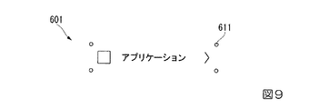
図9は、本発明の一実施形態に係るバー状のパネル601の構成例を示す図である。このパネル601は、例えば、図8に示されるパネル502に相当するものを例としている。
パネル601の枠は、4個の点611(図9では、1個の点のみに符号を付してある)から構成されており、これら4個の点611を結んで構成される。また、制御部130は、パネル601に、設定された図形や文字など(図9の例では、「□ アプリケーション >」という図形や文字など)を表示する。
各点611は、例えば、画素位置(X,Y)の点と一致する。本実施形態では、パネル601の枠上に存在する全ての画素位置の点ではなく、長方形の4個の頂点の画素位置の点を用いてパネル601の枠が構成されている。
FIG. 9 is a diagram illustrating a configuration example of a bar-shaped
The frame of the
Each
<パネルがユーザにより押下された場合の表示>
本実施形態では、画面のスクロールは行われておらず、スクロールは停止した状態であるとする。
他の例として、画面がスクロール中である場合には、例えば、画面がスクロール中である場合における表示態様(例えば、あらかじめ定められたもの)に従って表示画面の表示情報が制御される。なお、例えば、画面がスクロール中である場合に、本実施形態に係る表示態様が採用されてもよく、或いは、本実施形態に係る表示態様と他の表示態様とが組み合わされて用いられてもよい。
<Display when the panel is pressed by the user>
In this embodiment, it is assumed that the screen is not scrolled and the scrolling is stopped.
As another example, when the screen is being scrolled, for example, display information on the display screen is controlled according to a display mode (for example, predetermined one) when the screen is being scrolled. For example, when the screen is being scrolled, the display mode according to the present embodiment may be adopted, or the display mode according to the present embodiment may be used in combination with another display mode. Good.
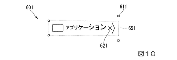
図10は、本実施形態に係るパネル601がユーザにより押下された場合におけるパネル601の変形の概略の一例を示す図である。
図10には、表示画面上において、パネル601の枠に対して、枠内に存在する点(押下の点)621がユーザの指により押下された場合に、制御部130が当該押下の点621に基づいて制御を行うことにより表示画面に表示されるパネル601の枠の形状の一例(パネル601の変形の一例)を示してある。また、図10には、参考として、変形前におけるパネル601の形状(元のパネル形状)651も示してあるが、これは実際には表示画面には表示されない。
図10の例では、変形後におけるパネル601の枠は、変形後における4個の点611(図10では、1個の点のみに符号を付してある)から構成され、これら変形後における4個の点611を結んで構成される。
FIG. 10 is a diagram illustrating an example of an outline of deformation of the
In FIG. 10, when a point (pressed point) 621 existing in the frame is pressed by the user's finger with respect to the frame of the
In the example of FIG. 10, the frame of the
ここで、パネル601の枠を構成する各点611の位置を変化させる方法としては、第1実施形態で説明した方法(図4〜図6における、押下の点に応じて、枠を構成する各点の位置を変化させる方法)と同様な方法を用いる。
なお、本実施形態に係るバー状のパネル601については、第1実施形態に係る正方形のパネルに対して、枠の形状が異なり、枠を構成する点の数が少なくなったものと、とらえることができる。
Here, as a method of changing the position of each
Note that the bar-shaped
また、制御部130は、パネル601に設定された図形や文字など(図10の例では、「□ アプリケーション >」という図形や文字など)についても、押下の点611に応じて変形させて表示するように制御する。本実施形態では、例えば、制御部130は、押下の点611或いは押下の点611に応じて変形させられるパネル601の枠(変形後のパネル601の枠)に応じて、当該パネル601に設定された図形や文字などを変形させる。
In addition, the
具体例として、制御部130は、パネル601の枠内の右の方が押下されて当該枠の右の方が上下方向(縦方向)に広がって表示される場合には、設定された図形や文字などについても、右の方について上下方向(縦方向)に広がるように、変形させ、同様に、パネル601の枠内の左の方が押下されて当該枠の左の方が上下方向(縦方向)に広がって表示される場合には、設定された図形や文字などについても、左の方について上下方向(縦方向)に広がるように、変形させる。
また、具体例として、制御部130は、パネル601の枠内の点が押下された場合には、設定された図形や文字などを左右方向(横方向)に広がるように変形させる。この左右方向(横方向)に広がるように変形させる方法としては、例えば、図形や文字などの元の位置に対して右方向のみに広がるように変形させる方法が用いられてもよく、或いは、図形や文字などの元の位置に対して左方向のみに広がるように変形させる方法が用いられてもよく、或いは、図形や文字などの元の位置に対して左右の両方の方向に広がるように変形させる方法が用いられてもよい。
As a specific example, when the right side in the frame of the
As a specific example, when a point in the frame of the
図10の例では、バー状のパネル601の枠内における右方の端の付近の位置(押下の点621の位置)がユーザにより押下されており、パネル601の枠を構成する4個の点611の中で、特に、右の端の付近(押下の部分の周辺)の点が拡張するように、パネル601の枠が変形している。これにより、変形後のパネル601の枠が、右方がより大きく開いた台形のような形状になっている。
また、図10の例では、「□ アプリケーション >」という図形や文字などについて、元の位置に対して、右の方へ拡張するように変形しており、且つ、右へ行くに従って上下に拡張するように変形している。
In the example of FIG. 10, the position in the vicinity of the right end in the frame of the bar-shaped panel 601 (the position of the pressing point 621) is pressed by the user, and the four points that constitute the frame of the
In the example of FIG. 10, the graphic or character “□ application>” is deformed so as to expand to the right with respect to the original position, and expands vertically as it goes to the right. It is deformed as follows.
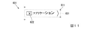
図11は、本実施形態に係るパネル601がユーザにより押下された場合におけるパネル601の変形の概略の一例を示す図である。
図11には、表示画面上において、パネル601の枠に対して、枠内に存在する点(押下の点)622がユーザの指により押下された場合に、制御部130が当該押下の点622に基づいて制御を行うことにより表示画面に表示されるパネル601の枠の形状の一例(パネル601の変形の一例)を示してある。また、図11には、参考として、変形前におけるパネル601の形状(元のパネル形状)651も示してあるが、これは実際には表示画面には表示されない。
図11の例では、変形後におけるパネル601の枠は、変形後における4個の点611(図11では、1個の点のみに符号を付してある)から構成され、これら変形後における4個の点611を結んで構成される。
FIG. 11 is a diagram illustrating an example of an outline of deformation of the
In FIG. 11, when a point (pressed point) 622 existing in the frame is pressed by the user's finger with respect to the frame of the
In the example of FIG. 11, the frame of the
本実施形態におけるパネル601の枠の変形の方法は、図10の例の場合と同様である。
図11の例では、バー状のパネル601の枠内における左方の端の付近の位置(押下の点622の位置)がユーザにより押下されており、パネル601の枠を構成する4個の点611の中で、特に、左の端の付近(押下の部分の周辺)の点が拡張するように、パネル601の枠が変形している。これにより、変形後のパネル601の枠が、左方がより大きく開いた台形のような形状になっている。
また、図11の例では、「□ アプリケーション >」という図形や文字などについて、元の位置に対して、右の方へ拡張するように変形しており、且つ、左へ行くに従って上下に拡張するように変形している。
The method of deforming the frame of the
In the example of FIG. 11, the position near the left end in the frame of the bar-shaped panel 601 (the position of the pressing point 622) has been pressed by the user, and the four points that constitute the frame of the
In the example of FIG. 11, the graphic or character “□ application>” is deformed so as to expand to the right with respect to the original position, and expands vertically as it goes to the left. It is deformed as follows.
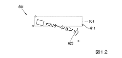
図12は、本実施形態に係るパネル601がユーザにより押下されたまま押下点が移動させられた場合におけるパネル601の変形の概略の一例を示す図である。
図12には、表示画面上において、パネル601の枠に対して、元の枠内に存在する点(初期の押下の点)がユーザの指により押下された後に、その指が押下したまま動かされて、元の枠の外に存在する点(押下の点)623が押下された場合に、制御部130が当該押下の点623に基づいて制御を行うことにより表示画面に表示されるパネル601の枠の形状の一例(パネル601の変形の一例)を示してある。また、図12には、参考として、変形前におけるパネル601の形状(元のパネル形状)651も示してあるが、これは実際には表示画面には表示されない。
図12の例では、変形後におけるパネル601の枠は、変形後における4個の点611(図12では、1個の点のみに符号を付してある)から構成され、これら変形後における4個の点611を結んで構成される。
FIG. 12 is a diagram illustrating an example of an outline of deformation of the
In FIG. 12, on the display screen, after the point (the initial pressing point) existing in the original frame is pressed by the user's finger with respect to the frame of the
In the example of FIG. 12, the frame of the
本実施形態におけるパネル601の枠の変形の方法は、図10の例の場合と同様な変形の方法に加えて、更に、押下点の移動に応じてパネル601の枠を構成する点611を移動させるように変形する方法を用いている。本実施形態では、これら2つの方法による変形を重ね合わせたものを、全体的な変形の結果として用いる。
図12の例では、バー状のパネル601の枠の外における右方の下方の位置(押下の点623の位置)がユーザにより押下されており、パネル601の枠を構成する4個の点611の中で、特に、右の端の付近(押下の部分の周辺)の点が拡張するように、パネル601の枠が変形しているとともに、右方へ行くほどパネル601が下方へ向かうように(例えば、パネル601が元の左端の辺の中心を軸として右回りに回転するように)変形している。また、図12の例では、「□ アプリケーション >」という図形や文字などについて、元の位置に対して、右下の方へ拡張するように変形しており、且つ、右へ行くに従って上下に拡張するように変形している。
The method for deforming the frame of the
In the example of FIG. 12, the right lower position (position of the pressing point 623) outside the frame of the bar-shaped
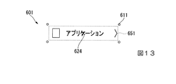
図13は、本実施形態に係るパネル601がユーザにより押下された場合におけるパネル601の変形の概略の一例を示す図である。
図13には、表示画面上において、パネル601の枠に対して、枠内に存在する点(押下の点)624がユーザの指により押下された場合に、制御部130が当該押下の点624に基づいて制御を行うことにより表示画面に表示されるパネル601の枠の形状の一例(パネル601の変形の一例)を示してある。また、図13には、参考として、変形前におけるパネル601の形状(元のパネル形状)651も示してあるが、これは実際には表示画面には表示されない。
図13の例では、変形後におけるパネル601の枠は、変形後における4個の点611(図13では、1個の点のみに符号を付してある)から構成され、これら変形後における4個の点611を結んで構成される。
FIG. 13 is a diagram illustrating a schematic example of deformation of the
In FIG. 13, when a point (pressed point) 624 existing in the frame is pressed by the user's finger with respect to the frame of the
In the example of FIG. 13, the frame of the
本実施形態におけるパネル601の枠の変形の方法は、図10の例の場合と同様である。
図13の例では、バー状のパネル601の枠内における中央の付近の位置(押下の点624の位置)がユーザにより押下されており、パネル601の枠を構成する4個の点611が、中央の付近(押下の部分)を中心にして均等に拡張するように、パネル601の枠が変形している。また、図13の例では、「□ アプリケーション >」という図形や文字などについて、元の位置に対して、右の方へ拡張するように変形しており、且つ、均等に上下に拡張するように変形している。
The method of deforming the frame of the
In the example of FIG. 13, the position in the vicinity of the center in the frame of the bar-shaped panel 601 (the position of the pressing point 624) is pressed by the user, and the four
以上のように、本実施形態に係る端末装置100によると、パネル601がユーザにより押下された場合や、そのまま押下位置が移動させられた場合における当該パネル601の表示を制御することで、表示画面に情報(本実施形態では、パネル601の情報)を表示するに際して、ユーザに対して視覚的に心地良さや視認性を与えることができる。これにより、例えば、ユーザに操作時の心地良さを与えることができ、また、視認性を向上させて、誤操作を低減することができる。
As described above, according to the
なお、本実施形態では、パネル601の形状を変形させる方法について説明したが、例えば、パネル601自体又はパネル601に設定された画像に関する色を変化させる方法が併用されてもよい。一例として、制御部130は、パネル601に対するユーザによる押下がある状態においては、押下がない状態と比べて、パネル601自体又はパネル601に設定された画像(本実施形態では、図形や文字など)に関する所定の色を異ならせる制御を行うことができる。
In the present embodiment, the method of changing the shape of the
[以上の実施形態に係る構成例]
<第1実施形態に係る端末装置の構成例>
一構成例として、画面が格子状に区切られた複数の格子領域から構成され、前記格子領域を単位として1個以上の前記格子領域からなる対象領域(第1実施形態では、パネル10〜14、20〜24、30、31、34の領域)毎に情報を表示する表示部(第1実施形態では、表示部150)と、前記対象領域に対する操作を検出する検出部(第1実施形態では、検出部110)と、前記検出部により操作が検出された前記対象領域を、前記操作が為された位置(第1実施形態では、押下の点221〜223)に応じて変形させて、前記表示部の画面に表示するように制御する制御部(第1実施形態では、制御部130)と、を備えることを特徴とする端末装置(第1実施形態では、端末装置100)である。
[Configuration example according to the above embodiment]
<Configuration Example of Terminal Device According to First Embodiment>
As one configuration example, the screen is composed of a plurality of lattice regions divided in a lattice shape, and the target region (in the first embodiment, the
一構成例として、前記対象領域の枠は、複数の点(第1実施形態では、枠を構成する点211)から構成され、前記制御部は、前記操作が為された位置と前記対象領域の枠を構成する各点の位置との間に働く所定の力(第1実施形態では、例えば、磁石による反発力)が発生するとみなして、前記検出部により操作が検出された前記対象領域の変形後の形状を計算する、ことを特徴とする端末装置である。
As an example of the configuration, the frame of the target area includes a plurality of points (
<第2実施形態に係る端末装置の構成例>
一構成例として、画面が格子状に区切られた複数の格子領域から構成され、前記格子領域を単位として1個以上の前記格子領域からなる対象領域(第2実施形態では、パネル10〜14、20〜24、30、31、34の領域)毎に情報を表示する表示部(第2実施形態では、表示部150)と、前記対象領域に対する操作を検出する検出部(第2実施形態では、検出部110)と、前記検出部により操作が非検出である(つまり、検出されない)前記対象領域を、あらかじめ定められた操作(第2実施形態では、図7を参照して説明した操作)が為されたとみなして変形させて、前記表示部の画面に表示するように制御する制御部(第2実施形態では、制御部130)と、を備えることを特徴とする端末装置(第2実施形態では、端末装置100)である。
<Configuration Example of Terminal Device According to Second Embodiment>
As one configuration example, the screen is configured by a plurality of grid areas divided in a grid pattern, and the target area (in the second embodiment,
<第3実施形態に係る端末装置の構成例>
一構成例として、画面に長方形の対象領域(第3実施形態では、パネル501〜506の領域)毎に情報を表示する表示部(第3実施形態では、表示部150)と、前記対象領域に対する操作を検出する検出部(第3実施形態では、検出部110)と、前記検出部により操作が検出された前記対象領域を、前記操作が為された位置(第3実施形態では、押下の点621〜624)に応じて変形させるとともに、前記対象領域に対応する情報の表示態様を変化させて、前記表示部の画面に表示するように制御する制御部(第3実施形態では、制御部130)と、を備えることを特徴とする端末装置(第3実施形態では、端末装置100)である。
<Configuration Example of Terminal Device According to Third Embodiment>
As a configuration example, a display unit (
<第1実施形態に係る表示プログラムの構成例>
一構成例として、コンピュータ(第1実施形態では、端末装置100を構成するコンピュータ)に、画面が格子状に区切られた複数の格子領域の当該格子領域を単位として1個以上の前記格子領域からなる対象領域毎に情報を表示する手順と、前記対象領域に対する操作を検出する手順と、前記操作が検出された前記対象領域を、前記操作が為された位置に応じて変形させて、前記画面に表示するように制御する手順と、を実行させるための表示プログラムである。
<Configuration Example of Display Program According to First Embodiment>
As one configuration example, a computer (in the first embodiment, a computer constituting the terminal device 100) can be configured to use one or more lattice regions as a unit of the lattice regions of a plurality of lattice regions divided in a lattice shape. A procedure for displaying information for each target area, a procedure for detecting an operation on the target area, and the target area where the operation is detected is deformed according to a position where the operation is performed, and the screen And a display program for executing the procedure of controlling to display on the screen.
<第2実施形態に係る表示プログラムの構成例>
一構成例として、コンピュータ(第2実施形態では、端末装置100を構成するコンピュータ)に、画面が格子状に区切られた複数の格子領域の当該格子領域を単位として1個以上の前記格子領域からなる対象領域毎に情報を表示する手順と、前記対象領域に対する操作を検出する手順と、前記操作が非検出である前記対象領域を、あらかじめ定められた操作が為されたとみなして変形させて、前記画面に表示するように制御する手順と、を実行させるための表示プログラムである。
<Example of Configuration of Display Program According to Second Embodiment>
As one configuration example, a computer (in the second embodiment, a computer configuring the terminal device 100) can be configured to use one or more lattice regions as a unit of the lattice regions of a plurality of lattice regions divided in a lattice shape. A procedure for displaying information for each target area, a procedure for detecting an operation on the target area, and transforming the target area in which the operation is not detected, assuming that a predetermined operation has been performed, A display program for executing a procedure for controlling to display on the screen.
<第3実施形態に係る表示プログラムの構成例>
一構成例として、コンピュータ(第3実施形態では、端末装置100を構成するコンピュータ)に、画面に長方形の対象領域毎に情報を表示する手順と、前記対象領域に対する操作を検出する手順と、前記操作が検出された前記対象領域を、前記操作が為された位置に応じて変形させるとともに、前記対象領域に対応する情報の表示態様を変化させて、前記画面に表示するように制御する手順と、を実行させるための表示プログラムである。
<Example of Configuration of Display Program According to Third Embodiment>
As one configuration example, a procedure for displaying information for each rectangular target area on a screen on a computer (in the third embodiment, a computer constituting the terminal device 100), a procedure for detecting an operation on the target area, A procedure for controlling the target area where the operation is detected to be deformed according to the position where the operation is performed and changing the display mode of the information corresponding to the target area to display the information on the screen; , A display program for executing.
[以上の実施形態のまとめ]
以上、この発明の実施形態について図面を参照して詳述してきたが、具体的な構成はこの実施形態に限られるものではなく、この発明の要旨を逸脱しない範囲の設計等も含まれる。
[Summary of the above embodiments]
The embodiment of the present invention has been described in detail with reference to the drawings. However, the specific configuration is not limited to this embodiment, and includes designs and the like that do not depart from the gist of the present invention.
なお、上記に説明した端末装置を実現するためのプログラムをコンピュータ読み取り可能な記録媒体に記録して、この記録媒体に記録されたプログラムをコンピュータシステムに読み込ませ、実行することにより、実行処理を行ってもよい。なお、ここでいう「コンピュータシステム」とは、OSや周辺機器等のハードウェアを含むものであってもよい。 The program for realizing the terminal device described above is recorded on a computer-readable recording medium, and the program recorded on the recording medium is read into the computer system and executed to execute the execution process. May be. Here, the “computer system” may include an OS and hardware such as peripheral devices.
また、「コンピュータシステム」は、WWWシステムを利用している場合であれば、ホームページ提供環境(あるいは表示環境)も含むものとする。また、「コンピュータ読み取り可能な記録媒体」とは、フレキシブルディスク、光磁気ディスク、ROM、フラッシュメモリ等の書き込み可能な不揮発性メモリ、CD−ROM等の可搬媒体、コンピュータシステムに内蔵されるハードディスク等の記憶装置のことをいう。 Further, the “computer system” includes a homepage providing environment (or display environment) if a WWW system is used. The “computer-readable recording medium” means a flexible disk, a magneto-optical disk, a ROM, a writable nonvolatile memory such as a flash memory, a portable medium such as a CD-ROM, a hard disk built in a computer system, etc. This is a storage device.
更に「コンピュータ読み取り可能な記録媒体」とは、インターネット等のネットワークや電話回線等の通信回線を介してプログラムが送信された場合のサーバやクライアントとなるコンピュータシステム内部の揮発性メモリ(例えばDRAM(Dynamic Random Access Memory))のように、一定時間プログラムを保持しているものも含むものとする。
また、上記プログラムは、このプログラムを記憶装置等に格納したコンピュータシステムから、伝送媒体を介して、あるいは、伝送媒体中の伝送波により他のコンピュータシステムに伝送されてもよい。ここで、プログラムを伝送する「伝送媒体」は、インターネット等のネットワーク(通信網)や電話回線等の通信回線(通信線)のように情報を伝送する機能を有する媒体のことをいう。
また、上記プログラムは、前述した機能の一部を実現するためのものであっても良い。
更に、前述した機能をコンピュータシステムにすでに記録されているプログラムとの組み合わせで実現できるもの、いわゆる差分ファイル(差分プログラム)であっても良い。
Furthermore, the “computer-readable recording medium” refers to a volatile memory (for example, DRAM (Dynamic) in a computer system that becomes a server or a client when a program is transmitted via a network such as the Internet or a communication line such as a telephone line. Random Access Memory)) that holds a program for a certain period of time is also included.
The program may be transmitted from a computer system storing the program in a storage device or the like to another computer system via a transmission medium or by a transmission wave in the transmission medium. Here, the “transmission medium” for transmitting the program refers to a medium having a function of transmitting information, such as a network (communication network) such as the Internet or a communication line (communication line) such as a telephone line.
The program may be for realizing a part of the functions described above.
Furthermore, what can implement | achieve the function mentioned above in combination with the program already recorded on the computer system, and what is called a difference file (difference program) may be sufficient.
10〜14、20〜24、30、31、34、201、501〜506、601…パネル(領域)、100…端末装置、110…検出部、120…記憶部、130…制御部、140…画像処理部、150…表示部、211、611…点、221〜223、621〜624…押下の点、251、651…元のパネル形状、301…疑似的な指押下の範囲 10-14, 20-24, 30, 31, 34, 201, 501-506, 601 ... panel (area), 100 ... terminal device, 110 ... detection unit, 120 ... storage unit, 130 ... control unit, 140 ... image Processing unit, 150 ... display unit, 211, 611 ... point, 221 to 223, 621 to 624 ... point of pressing, 251 and 651 ... original panel shape, 301 ... range of pseudo finger pressing
Claims (6)
前記対象領域に対する操作を検出する検出部と、
前記検出部により操作が検出された前記対象領域を、前記操作が為された位置に応じて変形させて、前記表示部の画面に表示するように制御する制御部と、を備え、
前記制御部は、前記操作が為された位置と前記対象領域の枠との間に働く所定の力が発生するとみなして、前記検出部により操作が検出された前記対象領域の変形後の形状を計算する、
ことを特徴とする端末装置。 A display unit configured to display information for each target area composed of one or more grid areas, each of which is composed of a plurality of grid areas partitioned in a grid pattern;
A detection unit for detecting an operation on the target region;
A control unit configured to control the target region, in which an operation is detected by the detection unit, to be deformed according to the position where the operation is performed and to be displayed on the screen of the display unit ,
The control unit considers that a predetermined force acting between the position where the operation is performed and the frame of the target region is generated, and determines the shape of the target region after the operation detected by the detection unit after deformation. calculate,
A terminal device characterized by that.
前記対象領域に対する操作を検出する検出部と、
前記検出部により操作が非検出である前記対象領域を、あらかじめ定められた操作が為されたとみなして変形させて、前記表示部の画面に表示するように制御する制御部と、を備え、
前記制御部は、前記操作が為されたとみなされる位置と前記対象領域の枠との間に働く所定の力が発生するとみなして、前記検出部により操作が非検出である前記対象領域の変形後の形状を計算する、
ことを特徴とする端末装置。 A display unit configured to display information for each target area composed of one or more grid areas, each of which is composed of a plurality of grid areas partitioned in a grid pattern;
A detection unit for detecting an operation on the target region;
A control unit that controls the target region, which is undetected by the detection unit, to be transformed by assuming that a predetermined operation has been performed, and to display on the screen of the display unit ,
The control unit assumes that a predetermined force acting between a position where the operation is considered to be performed and a frame of the target region is generated, and after the deformation of the target region where the operation is not detected by the detection unit Calculate the shape of the
A terminal device characterized by that.
前記対象領域に対する操作を検出する検出部と、
前記検出部により操作が検出された前記対象領域を、前記操作が為された位置に応じて変形させるとともに、前記対象領域に対応する情報の表示態様を変化させて、前記表示部の画面に表示するように制御する制御部と、を備え、
前記制御部は、前記操作が為された位置と前記対象領域の枠との間に働く所定の力が発生するとみなして、前記検出部により操作が検出された前記対象領域の変形後の形状を計算する、
ことを特徴とする端末装置。 A display unit that displays information for each rectangular target area on the screen;
A detection unit for detecting an operation on the target region;
The target area where the operation is detected by the detection unit is deformed according to the position where the operation is performed, and the display mode of information corresponding to the target area is changed and displayed on the screen of the display unit and a control unit for controlling to, the,
The control unit considers that a predetermined force acting between the position where the operation is performed and the frame of the target region is generated, and determines the shape of the target region after the operation detected by the detection unit after deformation. calculate,
A terminal device characterized by that.
画面が格子状に区切られた複数の格子領域の当該格子領域を単位として1個以上の前記格子領域からなる対象領域毎に情報を表示する手順と、
前記対象領域に対する操作を検出する手順と、
前記操作が検出された前記対象領域を、前記操作が為された位置に応じて変形させて、前記画面に表示するように制御する手順と、を実行させるための表示プログラムであって、
前記操作が為された位置と前記対象領域の枠との間に働く所定の力が発生するとみなして、前記操作が検出された前記対象領域の変形後の形状を計算する、
表示プログラム。 On the computer,
A procedure for displaying information for each target region composed of one or more lattice regions, with the lattice region as a unit of a plurality of lattice regions divided into a lattice shape on the screen;
Detecting an operation on the target area;
A display program for causing the target area in which the operation is detected to be deformed according to the position where the operation is performed and controlled to be displayed on the screen .
Considering that a predetermined force acting between the position where the operation is performed and the frame of the target area occurs, and calculating a deformed shape of the target area where the operation is detected.
Display program .
画面が格子状に区切られた複数の格子領域の当該格子領域を単位として1個以上の前記格子領域からなる対象領域毎に情報を表示する手順と、
前記対象領域に対する操作を検出する手順と、
前記操作が非検出である前記対象領域を、あらかじめ定められた操作が為されたとみなして変形させて、前記画面に表示するように制御する手順と、を実行させるための表示プログラムであって、
前記操作が為されたとみなされる位置と前記対象領域の枠との間に働く所定の力が発生するとみなして、前記操作が非検出である前記対象領域の変形後の形状を計算する、
表示プログラム。 On the computer,
A procedure for displaying information for each target region composed of one or more lattice regions, with the lattice region as a unit of a plurality of lattice regions divided into a lattice shape on the screen;
Detecting an operation on the target area;
A display program for executing the procedure of controlling the target area where the operation is undetected to be deformed by assuming that a predetermined operation has been performed, and displaying it on the screen ,
Considering that a predetermined force acting between the position where the operation is considered to have been performed and the frame of the target area occurs, and calculating the deformed shape of the target area where the operation is not detected,
Display program .
画面に長方形の対象領域毎に情報を表示する手順と、
前記対象領域に対する操作を検出する手順と、
前記操作が検出された前記対象領域を、前記操作が為された位置に応じて変形させるとともに、前記対象領域に対応する情報の表示態様を変化させて、前記画面に表示するように制御する手順と、を実行させるための表示プログラムであって、
前記操作が為された位置と前記対象領域の枠との間に働く所定の力が発生するとみなして、前記操作が検出された前記対象領域の変形後の形状を計算する、
表示プログラム。 On the computer,
A procedure for displaying information for each rectangular target area on the screen;
Detecting an operation on the target area;
A procedure for controlling the target area where the operation is detected to be deformed according to the position where the operation is performed, and changing the display mode of information corresponding to the target area to display on the screen. a display program for causing the the run,
Considering that a predetermined force acting between the position where the operation is performed and the frame of the target area occurs, and calculating a deformed shape of the target area where the operation is detected.
Display program .
Priority Applications (1)
| Application Number | Priority Date | Filing Date | Title |
|---|---|---|---|
| JP2013010495A JP6091908B2 (en) | 2013-01-23 | 2013-01-23 | Terminal device and display program |
Applications Claiming Priority (1)
| Application Number | Priority Date | Filing Date | Title |
|---|---|---|---|
| JP2013010495A JP6091908B2 (en) | 2013-01-23 | 2013-01-23 | Terminal device and display program |
Publications (2)
| Publication Number | Publication Date |
|---|---|
| JP2014142792A JP2014142792A (en) | 2014-08-07 |
| JP6091908B2 true JP6091908B2 (en) | 2017-03-08 |
Family
ID=51424024
Family Applications (1)
| Application Number | Title | Priority Date | Filing Date |
|---|---|---|---|
| JP2013010495A Active JP6091908B2 (en) | 2013-01-23 | 2013-01-23 | Terminal device and display program |
Country Status (1)
| Country | Link |
|---|---|
| JP (1) | JP6091908B2 (en) |
Families Citing this family (1)
| Publication number | Priority date | Publication date | Assignee | Title |
|---|---|---|---|---|
| CN110780969B (en) * | 2019-10-31 | 2022-12-30 | 抖音视界有限公司 | Method and device for operating electronic equipment, electronic equipment and storage medium |
Family Cites Families (7)
| Publication number | Priority date | Publication date | Assignee | Title |
|---|---|---|---|---|
| JPH07230352A (en) * | 1993-09-16 | 1995-08-29 | Hitachi Ltd | Touch position detecting device and touch instruction processor |
| JP2001242980A (en) * | 2000-03-02 | 2001-09-07 | Yasufumi Mase | Information display system |
| JP5256712B2 (en) * | 2007-11-28 | 2013-08-07 | ブラザー工業株式会社 | Installation program and information processing apparatus |
| JP5297121B2 (en) * | 2008-08-29 | 2013-09-25 | Necカシオモバイルコミュニケーションズ株式会社 | Terminal device and program |
| KR101640463B1 (en) * | 2009-05-19 | 2016-07-18 | 삼성전자 주식회사 | Operation Method And Apparatus For Portable Device |
| JP2011034476A (en) * | 2009-08-05 | 2011-02-17 | Seiko Epson Corp | Information input device and information input method |
| JP4908626B1 (en) * | 2010-12-28 | 2012-04-04 | 株式会社東芝 | Display control apparatus and display control method |
-
2013
- 2013-01-23 JP JP2013010495A patent/JP6091908B2/en active Active
Also Published As
| Publication number | Publication date |
|---|---|
| JP2014142792A (en) | 2014-08-07 |
Similar Documents
| Publication | Publication Date | Title |
|---|---|---|
| JP6938706B2 (en) | User interface program and game program | |
| JP6122037B2 (en) | Content moving method and apparatus in terminal | |
| US9436379B2 (en) | Control method and electronic device | |
| US20140002502A1 (en) | Method and apparatus for outputting graphics to a display | |
| JP5671921B2 (en) | Information processing apparatus, information processing method, and program | |
| JP2011520209A5 (en) | ||
| US9685143B2 (en) | Display control device, display control method, and computer-readable storage medium for changing a representation of content displayed on a display screen | |
| KR20100041006A (en) | A user interface controlling method using three dimension multi-touch | |
| JP2016206740A (en) | User interface program | |
| US10120540B2 (en) | Visual feedback for user interface navigation on television system | |
| JP2011145779A (en) | Information processing apparatus, information processing method thereof, and program | |
| CN102081493A (en) | Mobile electronic device and control method of 3D (three-dimensional) operation interface thereof | |
| KR20140133072A (en) | Mobile device and method for operating the same | |
| JP5880024B2 (en) | Information processing apparatus and program | |
| JP6091908B2 (en) | Terminal device and display program | |
| JP2014134867A (en) | Information processing terminal | |
| JP6197559B2 (en) | Object operation system, object operation control program, and object operation control method | |
| JP2009223532A (en) | Operation control method for icon interface | |
| JP6091907B2 (en) | Terminal device and display program | |
| JP6000482B1 (en) | User interface image display method and program | |
| JP5856343B1 (en) | User interface program and computer mounting method | |
| JP6016508B2 (en) | Display device | |
| JP6031363B2 (en) | Terminal device and display program | |
| JP2017016622A (en) | User interface program and computer implementation method |
Legal Events
| Date | Code | Title | Description |
|---|---|---|---|
| A621 | Written request for application examination |
Free format text: JAPANESE INTERMEDIATE CODE: A621 Effective date: 20151125 |
|
| A521 | Request for written amendment filed |
Free format text: JAPANESE INTERMEDIATE CODE: A821 Effective date: 20151126 |
|
| A977 | Report on retrieval |
Free format text: JAPANESE INTERMEDIATE CODE: A971007 Effective date: 20160905 |
|
| A131 | Notification of reasons for refusal |
Free format text: JAPANESE INTERMEDIATE CODE: A131 Effective date: 20160927 |
|
| A521 | Request for written amendment filed |
Free format text: JAPANESE INTERMEDIATE CODE: A523 Effective date: 20161124 |
|
| A521 | Request for written amendment filed |
Free format text: JAPANESE INTERMEDIATE CODE: A821 Effective date: 20161125 |
|
| TRDD | Decision of grant or rejection written | ||
| A01 | Written decision to grant a patent or to grant a registration (utility model) |
Free format text: JAPANESE INTERMEDIATE CODE: A01 Effective date: 20170110 |
|
| A61 | First payment of annual fees (during grant procedure) |
Free format text: JAPANESE INTERMEDIATE CODE: A61 Effective date: 20170208 |
|
| R150 | Certificate of patent or registration of utility model |
Ref document number: 6091908 Country of ref document: JP Free format text: JAPANESE INTERMEDIATE CODE: R150 |
|
| R250 | Receipt of annual fees |
Free format text: JAPANESE INTERMEDIATE CODE: R250 |
|
| R250 | Receipt of annual fees |
Free format text: JAPANESE INTERMEDIATE CODE: R250 |
|
| R250 | Receipt of annual fees |
Free format text: JAPANESE INTERMEDIATE CODE: R250 |

