JP6087522B2 - Printing apparatus, printing apparatus control method, and program - Google Patents
Printing apparatus, printing apparatus control method, and program Download PDFInfo
- Publication number
- JP6087522B2 JP6087522B2 JP2012139822A JP2012139822A JP6087522B2 JP 6087522 B2 JP6087522 B2 JP 6087522B2 JP 2012139822 A JP2012139822 A JP 2012139822A JP 2012139822 A JP2012139822 A JP 2012139822A JP 6087522 B2 JP6087522 B2 JP 6087522B2
- Authority
- JP
- Japan
- Prior art keywords
- print data
- sheet
- image
- data
- Prior art date
- Legal status (The legal status is an assumption and is not a legal conclusion. Google has not performed a legal analysis and makes no representation as to the accuracy of the status listed.)
- Active
Links
Images


Classifications
-
- B—PERFORMING OPERATIONS; TRANSPORTING
- B65—CONVEYING; PACKING; STORING; HANDLING THIN OR FILAMENTARY MATERIAL
- B65H—HANDLING THIN OR FILAMENTARY MATERIAL, e.g. SHEETS, WEBS, CABLES
- B65H5/00—Feeding articles separated from piles; Feeding articles to machines
- B65H5/26—Duplicate, alternate, selective, or coacting feeds
-
- G—PHYSICS
- G06—COMPUTING; CALCULATING OR COUNTING
- G06F—ELECTRIC DIGITAL DATA PROCESSING
- G06F3/00—Input arrangements for transferring data to be processed into a form capable of being handled by the computer; Output arrangements for transferring data from processing unit to output unit, e.g. interface arrangements
- G06F3/12—Digital output to print unit, e.g. line printer, chain printer
- G06F3/1201—Dedicated interfaces to print systems
- G06F3/1223—Dedicated interfaces to print systems specifically adapted to use a particular technique
- G06F3/1237—Print job management
- G06F3/126—Job scheduling, e.g. queuing, determine appropriate device
- G06F3/1264—Job scheduling, e.g. queuing, determine appropriate device by assigning post-processing resources
-
- B—PERFORMING OPERATIONS; TRANSPORTING
- B65—CONVEYING; PACKING; STORING; HANDLING THIN OR FILAMENTARY MATERIAL
- B65H—HANDLING THIN OR FILAMENTARY MATERIAL, e.g. SHEETS, WEBS, CABLES
- B65H31/00—Pile receivers
- B65H31/24—Pile receivers multiple or compartmented, e.d. for alternate, programmed, or selective filling
-
- B—PERFORMING OPERATIONS; TRANSPORTING
- B65—CONVEYING; PACKING; STORING; HANDLING THIN OR FILAMENTARY MATERIAL
- B65H—HANDLING THIN OR FILAMENTARY MATERIAL, e.g. SHEETS, WEBS, CABLES
- B65H33/00—Forming counted batches in delivery pile or stream of articles
- B65H33/06—Forming counted batches in delivery pile or stream of articles by displacing articles to define batches
- B65H33/08—Displacing whole batches, e.g. forming stepped piles
-
- B—PERFORMING OPERATIONS; TRANSPORTING
- B65—CONVEYING; PACKING; STORING; HANDLING THIN OR FILAMENTARY MATERIAL
- B65H—HANDLING THIN OR FILAMENTARY MATERIAL, e.g. SHEETS, WEBS, CABLES
- B65H33/00—Forming counted batches in delivery pile or stream of articles
- B65H33/06—Forming counted batches in delivery pile or stream of articles by displacing articles to define batches
- B65H33/10—Displacing the end articles of a batch
-
- B—PERFORMING OPERATIONS; TRANSPORTING
- B65—CONVEYING; PACKING; STORING; HANDLING THIN OR FILAMENTARY MATERIAL
- B65H—HANDLING THIN OR FILAMENTARY MATERIAL, e.g. SHEETS, WEBS, CABLES
- B65H43/00—Use of control, checking, or safety devices, e.g. automatic devices comprising an element for sensing a variable
-
- B—PERFORMING OPERATIONS; TRANSPORTING
- B65—CONVEYING; PACKING; STORING; HANDLING THIN OR FILAMENTARY MATERIAL
- B65H—HANDLING THIN OR FILAMENTARY MATERIAL, e.g. SHEETS, WEBS, CABLES
- B65H7/00—Controlling article feeding, separating, pile-advancing, or associated apparatus, to take account of incorrect feeding, absence of articles, or presence of faulty articles
- B65H7/20—Controlling associated apparatus
-
- G—PHYSICS
- G06—COMPUTING; CALCULATING OR COUNTING
- G06F—ELECTRIC DIGITAL DATA PROCESSING
- G06F3/00—Input arrangements for transferring data to be processed into a form capable of being handled by the computer; Output arrangements for transferring data from processing unit to output unit, e.g. interface arrangements
- G06F3/12—Digital output to print unit, e.g. line printer, chain printer
- G06F3/1201—Dedicated interfaces to print systems
- G06F3/1278—Dedicated interfaces to print systems specifically adapted to adopt a particular infrastructure
- G06F3/1291—Pool of printer devices: self-managing printing devices in a network, e.g. without a server
-
- G—PHYSICS
- G06—COMPUTING; CALCULATING OR COUNTING
- G06K—GRAPHICAL DATA READING; PRESENTATION OF DATA; RECORD CARRIERS; HANDLING RECORD CARRIERS
- G06K15/00—Arrangements for producing a permanent visual presentation of the output data, e.g. computer output printers
- G06K15/40—Details not directly involved in printing, e.g. machine management, management of the arrangement as a whole or of its constitutive parts
- G06K15/4025—Managing optional units, e.g. sorters, document feeders
- G06K15/403—Managing optional units, e.g. sorters, document feeders handling the outputted documents, e.g. staplers, sorters
-
- B—PERFORMING OPERATIONS; TRANSPORTING
- B65—CONVEYING; PACKING; STORING; HANDLING THIN OR FILAMENTARY MATERIAL
- B65H—HANDLING THIN OR FILAMENTARY MATERIAL, e.g. SHEETS, WEBS, CABLES
- B65H2301/00—Handling processes for sheets or webs
- B65H2301/40—Type of handling process
- B65H2301/42—Piling, depiling, handling piles
- B65H2301/421—Forming a pile
- B65H2301/4213—Forming a pile of a limited number of articles, e.g. buffering, forming bundles
-
- B—PERFORMING OPERATIONS; TRANSPORTING
- B65—CONVEYING; PACKING; STORING; HANDLING THIN OR FILAMENTARY MATERIAL
- B65H—HANDLING THIN OR FILAMENTARY MATERIAL, e.g. SHEETS, WEBS, CABLES
- B65H2301/00—Handling processes for sheets or webs
- B65H2301/40—Type of handling process
- B65H2301/42—Piling, depiling, handling piles
- B65H2301/421—Forming a pile
- B65H2301/4219—Forming a pile forming a pile in which articles are offset from each other, e.g. forming stepped pile
-
- B—PERFORMING OPERATIONS; TRANSPORTING
- B65—CONVEYING; PACKING; STORING; HANDLING THIN OR FILAMENTARY MATERIAL
- B65H—HANDLING THIN OR FILAMENTARY MATERIAL, e.g. SHEETS, WEBS, CABLES
- B65H2408/00—Specific machines
- B65H2408/10—Specific machines for handling sheet(s)
- B65H2408/11—Sorters or machines for sorting articles
-
- B—PERFORMING OPERATIONS; TRANSPORTING
- B65—CONVEYING; PACKING; STORING; HANDLING THIN OR FILAMENTARY MATERIAL
- B65H—HANDLING THIN OR FILAMENTARY MATERIAL, e.g. SHEETS, WEBS, CABLES
- B65H2511/00—Dimensions; Position; Numbers; Identification; Occurrences
- B65H2511/40—Identification
- B65H2511/415—Identification of job
-
- B—PERFORMING OPERATIONS; TRANSPORTING
- B65—CONVEYING; PACKING; STORING; HANDLING THIN OR FILAMENTARY MATERIAL
- B65H—HANDLING THIN OR FILAMENTARY MATERIAL, e.g. SHEETS, WEBS, CABLES
- B65H2801/00—Application field
- B65H2801/24—Post -processing devices
- B65H2801/27—Devices located downstream of office-type machines
-
- G—PHYSICS
- G03—PHOTOGRAPHY; CINEMATOGRAPHY; ANALOGOUS TECHNIQUES USING WAVES OTHER THAN OPTICAL WAVES; ELECTROGRAPHY; HOLOGRAPHY
- G03G—ELECTROGRAPHY; ELECTROPHOTOGRAPHY; MAGNETOGRAPHY
- G03G2215/00—Apparatus for electrophotographic processes
- G03G2215/00362—Apparatus for electrophotographic processes relating to the copy medium handling
- G03G2215/00886—Sorting or discharging
- G03G2215/00894—Placing job divider sheet
Description
本発明は、印刷ジョブに基づいてシートに画像を印刷することが可能な印刷装置、印刷装置の制御方法、及びプログラムに関するものである。 The present invention relates to a printing apparatus capable of printing an image on a sheet based on the print job, it relates to a control method, and program of the printing apparatus.
従来の印刷装置では、複数の異なる出力物を順次作成し、それらを単一のまとまりとして扱うというニーズが存在する。 In a conventional printing apparatus, there is a need to sequentially create a plurality of different output products and handle them as a single unit.
例えば、本社と複数の支社が存在し、本社内に設置された印刷センターにて、各支社向けの書類を生成し、支社単位でそれらの書類を配送するような場合を考える。その場合、書類の内容は支社毎に特化したものとなる。 For example, consider a case where there is a head office and a plurality of branch offices, and a document for each branch office is generated at a printing center installed in the head office, and those documents are delivered in units of branch offices. In that case, the contents of the document will be specific to each branch office.
より具体的には次のようなケース、例えば本社、支社A、支社B、支社Cが存在する場合を想定する。また、ドキュメントD、E、F、G、H、I、J、K、Lがあり、各ドキュメントはそれぞれ下記の支社に配送する場合を想定する。
支社A: D、E、F
支社B: G、H
支社C: I、J、K、L
More specifically, the following case is assumed, for example, where a head office, a branch office A, a branch office B, and a branch office C exist. Further, there are documents D, E, F, G, H, I, J, K, and L, and each document is assumed to be delivered to the following branch office.
Branch A: D, E, F
Branch B: G, H
Branch C: I, J, K, L
本社内に設置された印刷センターでは上述の支社毎に配送されるD、E、F、G、H、I、J、K、Lの計9種のドキュメントを該印刷センター内に設置されたデジタル印刷機にて印刷処理する。ただし、配送先D、E、F、G、H、I、J、K、Lを仕分ける際の効率を考慮し、支社毎のドキュメント出力は連続的に行なわれることが一般的である。
すなわち、例えば配送先が支社AであるドキュメントD、E、Fは連続的に処理される。仮に、前述のようにしなかった場合、例えばD、E、G、H、Fなどのような順序で出力した場合、支社A向けの配送用ドキュメントに配送先が支社Bのドキュメントが混在する。その場合、ユーザは、配送前に、支社B向けの印刷対象データG、Hを出力物から取り除く処理を実施しなくてはならない。
このような作業は煩雑であるばかりか、人的ミス等を招くおそれがあり、極めて非効率的である。配送先毎のドキュメントを連続的に出力することの必要性は上述のような理由によるものである。 なお、特許文献1には、1つのドキュメントを1つのジョブとして受け付け、ジョブごとに出力物を仕分けて排紙する印刷システムが記載されている。
In the printing center installed in the head office, a total of nine types of documents D, E, F, G, H, I, J, K, and L delivered to each branch office are digitally installed in the printing center. Print processing on the printing machine. However, in consideration of the efficiency in sorting the delivery destinations D, E, F, G, H, I, J, K, and L, it is common that document output for each branch office is continuously performed.
That is, for example, documents D, E, and F whose delivery destination is branch office A are continuously processed. If it is not performed as described above, for example, when output is performed in the order of D, E, G, H, F, etc., a document for which the delivery destination is branch B is mixed with a delivery document for branch office A. In that case, the user must perform a process of removing the print target data G and H for the branch office B from the output before delivery.
Such an operation is not only complicated, but may cause human error, and is extremely inefficient. The necessity of continuously outputting the document for each delivery destination is for the reason described above.
デジタル印刷機を用いて、複数の配送先に対してそれぞれ異なる種類の出力物を連続的に生成することの目的および利便性は背景技術において記載した通りである。しかしながら、上述のようなケースにおいて、目的を効率的に達成することを考慮した場合、利便性を向上させる上でのさらなる課題が存在する。
上述の例を引用し具体的に説明する。
The purpose and convenience of continuously generating different types of output products for a plurality of delivery destinations using a digital printer are as described in the background art. However, in the case as described above, there is a further problem in improving convenience when considering achieving the object efficiently.
A specific description will be given with reference to the above example.
配送先である支社A用にドキュメントD、E、F、支社B用にG、H、支社C用にI、J、K、Lをそれぞれこの順序でデジタル印刷機によって出力したとする。デジタル印刷機の排出部にはD、E、F、G、H、I、J、K、Lの順序で出力物がスタックされることとなる。
この状態は、配送先毎に連続して出力されているため、背景技術にて述べたような配送先毎の印刷物中に他の配送先用の出力物が混在するようなケースは発生しない。
Assume that documents D, E, F for branch office A, which is a delivery destination, G, H for branch office B, and I, J, K, L for branch office C are output in this order by a digital printing machine. Outputs are stacked in the order of D, E, F, G, H, I, J, K, and L in the discharge unit of the digital printing machine.
Since this state is continuously output for each delivery destination, there is no case where output materials for other delivery destinations are mixed in the printed matter for each delivery destination as described in the background art.
しかしながら、排出部にD〜Lの9個のドキュメントが一様にスタックされた場合、そのスタックされた出力物を配送先単位に仕分ける際に、ドキュメントの境界部を、ユーザは容易に認識できない。
そのため、ユーザは、印刷物の内容を確認しながら注意深く印刷物の境界および配送先の境界部分を探さなくてはならないという煩雑な作業をしなければならない。換言すれば、配送先毎の印刷物中に他の配送先の印刷物が混在しないケースであっても、一様にスタックされた印刷物束を配送先毎の印刷物に仕分ける作業は、依然として困難な作業を伴う。
However, when nine documents D to L are uniformly stacked on the discharge unit, the user cannot easily recognize the boundary portion of the document when sorting the stacked output products into units of delivery destinations.
For this reason, the user must perform a complicated operation of carefully searching for the boundary of the printed material and the boundary of the delivery destination while checking the contents of the printed material. In other words, even in a case where the printed materials of other delivery destinations do not coexist in the printed materials of each delivery destination, the task of sorting the uniformly stacked printed material bundles into the printed materials for each delivery destination is still difficult. Accompany.
デジタル印刷機には、特許文献1に記載されたような、1つのジョブの出力物を排紙するたびに出力物をずらして排紙する機能や1部数の出力物を排紙するたびに出力物をずらして排紙するといった仕分け機能がある。
ところが、デジタル印刷機の仕分け機能を利用して上述の各配送先向けのドキュメントD、E、F、G、H、I、J、K、Lを出力した場合であっても、課題は解消されない。仕分け機能を利用する事によって、全てのドキュメントをシフトされた状態で排紙することはできる。そうした場合、ドキュメントの境界部を誤って仕分けてしまうおそれは軽減できる。しかしながら、配送先の識別は依然として困難であることに変わりはない。すなわち、本来の目的である
支社A: D、E、F
支社B: G、H
支社C: I、J、K、L
のように仕分けなくてはならないところ、支社単位の区切りが明確とはならないため、下記のように誤って仕分けてしまう可能性がある。
支社A: D、E
支社B: F、G、H、I
支社C: J、K、L
The digital printing machine has a function of shifting the output material every time the output product of one job is discharged, as described in
However, even when the documents D, E, F, G, H, I, J, K, and L for each delivery destination are output using the sorting function of the digital printing machine, the problem is not solved. . By using the sorting function, all documents can be discharged in a shifted state. In such a case, it is possible to reduce the risk of erroneously sorting document boundaries. However, it is still difficult to identify the delivery destination. That is, branch office A which is the original purpose: D, E, F
Branch B: G, H
Branch C: I, J, K, L
However, since the division of the branch office unit is not clear, there is a possibility that it is mistakenly classified as follows.
Branch A: D, E
Branch B: F, G, H, I
Branch C: J, K, L
上記の誤りの例は、一例にすぎず、他にも配送先の境界がスタックされた出力物束において自明でないことが理由となり、ある支社向け用のドキュメントが誤って異なる支社の束として仕分けられてしまう可能性がある。
このような状況において正しく配送先毎の仕分け処理を行うためには、どのドキュメントがどの配送先用のものであるのかを仕分け処理を実施するオペレータが正確に認識した上で、注意深く作業しなければならない。しかしながら、このような作業は困難であり、かつ人的ミスが容易に発生することが予想される。
The above error example is only an example, and another reason is that a document for a branch office is mistakenly classified as a bundle of different branch offices because the boundary of the delivery destination is not obvious in the stacked output bundle. There is a possibility that.
In such a situation, in order to correctly perform the sorting process for each delivery destination, the operator who carries out the sorting process accurately recognizes which document is for which delivery destination, and must work carefully. Don't be. However, such work is difficult and human errors are expected to easily occur.
上記では一例として本社から各支社に印刷物を仕分けるケースを具体例として説明したが、他にも同様のケースは多々存在する。すなわち例えば別の一例としては、印刷センターにて、複数の配送先として個人が対応づけられるケースである。個人情報を含むような印刷物の誤配送は極力避けるべきである。 In the above description, the case where the printed matter is sorted from the head office to each branch office has been described as a specific example. However, there are many other similar cases. That is, for example, another example is a case where an individual is associated as a plurality of delivery destinations at a printing center. Misdelivery of printed materials that contain personal information should be avoided as much as possible.
本発明は、上記の課題を解決するためになされたもので、本発明の目的は、ユーザの仕分け負担を軽減できる仕組みを提供することである。 The present invention has been made to solve the above problems, an object of the present invention is to provide a mechanism that can reduce the sorting burden Yu over THE.
上記目的を達成する本発明の印刷装置は、第1の印刷データと第2の印刷データとが連結された1つの印刷ジョブを受信する受信手段と、前記受信手段により受信された印刷ジョブを実行することによりシートに画像を印刷する印刷手段と、前記印刷ジョブに含まれる仕分けを行わせるための所定情報を検出する検出手段と、前記検出手段が前記第1の印刷データと前記第2の印刷データの間で前記所定情報を検出していない場合、前記第2の印刷データに基づいて画像が印刷されたシートを前記第1の印刷データに基づいて画像が印刷されたシートと同じ位置に排出する第1の排出動作を実行し、前記検出手段が前記第1の印刷データと前記第2の印刷データの間で前記所定情報を検出した場合、前記第2の印刷データに基づいて画像が印刷されたシートを前記第1の印刷データに基づいて画像が印刷されたシートと異なる位置に排出する第2の排出動作を実行する排出手段と、を備えることを特徴とする。
また、本発明の印刷装置は、第1の印刷データと第2の印刷データとが連結された1つの印刷ジョブを受信する受信手段と、前記受信手段により受信された印刷ジョブを実行することによりシートに画像を印刷する印刷手段と、前記印刷ジョブに含まれる仕分けを行わせるための所定情報を検出する検出手段と、前記検出手段が前記第1の印刷データと前記第2の印刷データに関連付けられた前記所定情報を検出していない場合、前記第2の印刷データに基づいて画像が印刷されたシートを前記第1の印刷データに基づいて画像が印刷されたシートと同じ位置に排出する第1の排出動作を実行し、前記検出手段が前記第1の印刷データと前記第2の印刷データに関連付けられた前記所定情報を検出した場合、前記第2の印刷データに基づいて画像が印刷されたシートを前記第1の印刷データに基づいて画像が印刷されたシートと異なる位置に排出する第2の排出動作を実行する排出手段と、
を備えることを特徴とする。
The printing apparatus of the present invention that achieves the above-described object executes a print job received by the receiving unit and a receiving unit that receives one print job in which the first print data and the second print data are connected. printing and printing means for printing an image on a sheet, a detecting means for detecting a predetermined information for causing sort included in the print job, the detection means of the second and the first print data by When the predetermined information is not detected among the data, the sheet on which the image is printed based on the second print data is discharged to the same position as the sheet on which the image is printed based on the first print data. first executes the discharge operation, when the detecting means detects the predetermined information between the second print data and the first print data, image based on the second print data indicia Characterized in that and a discharge means for performing a second discharge operation for discharging the sheet with different positions on which an image is printed based has been the sheet to the first print data.
According to another aspect of the invention, the printing apparatus receives a single print job in which the first print data and the second print data are connected, and executes the print job received by the reception unit. Printing means for printing an image on a sheet; detection means for detecting predetermined information included in the print job; and detecting means associated with the first print data and the second print data If the predetermined information is not detected , a sheet on which an image is printed based on the second print data is discharged to the same position as a sheet on which an image is printed based on the first print data. perform one discharge operation, when said detecting means detects the predetermined information associated with the second print data and the first print data, based on the second print data A discharge means for performing a second discharge operation for discharging the sheet on which the image is printed on the sheet with different positions on which an image is printed based on the first print data,
It is characterized by providing.
本発明によれば、ユーザの仕分け負担を軽減できる。 According to the present invention, it is possible to reduce the sorting burden Yu over The.
次に本発明を実施するための最良の形態について図面を参照して説明する。
<システム構成の説明>
〔第1実施形態〕
図1は、本実施形態を示す印刷装置を適用する印刷システムの構成を説明する図である。本例は、POD(プリント・オン・デマンド)市場向けデジタル印刷機およびそれを用いたシステム例である。具体的には、ネットワーク100を介して、デジタル印刷機102、およびコンピュータ101が接続されたシステム例を示している。
図1において、デジタル印刷機102は、複数の異なる役割を持つ装置が相互に連結され、複雑なシート処理が可能なよう構成されている。以下、印刷装置を構成する各部位に関して説明する。
Next, the best mode for carrying out the present invention will be described with reference to the drawings.
<Description of system configuration>
[First Embodiment]
FIG. 1 is a diagram illustrating a configuration of a printing system to which a printing apparatus according to the present embodiment is applied. This example is a digital printing machine for the POD (print on demand) market and a system example using the same. Specifically, an example of a system in which a
In FIG. 1, the
デジタル印刷部1000は、展開されたイメージ画像データを後述する給紙部に格納された(シート)を搬送し、該シート上にトナーを用いて画像形成するための装置である。プリンタ部の一般的な構成および動作原理は下記のとおりである。
The
回転多面鏡(ポリゴンミラー等)が、画像データに応じて変調された、例えばレーザ光などの光線を入射させ、反射ミラーを介して反射走査光として感光ドラムに照射する。感光ドラム上に前記レーザ光によって形成された潜像はトナーによって現像され、転写ドラム上に貼り付けられたシート材、すなわちシートに対してトナー像を転写する。この一連の画像形成プロセスをイエロー(Y)、マゼンタ(M)、シアン(C)、ブラック(K)のトナーに対して順次実行することによりフルカラー画像が形成される。また、4色に加え、特色と呼ぶトナーや、透明トナーなどを転写可能とする構成としても良い。 A rotating polygon mirror (polygon mirror or the like) enters a light beam such as a laser beam, which is modulated according to image data, and irradiates the photosensitive drum as reflected scanning light through a reflecting mirror. The latent image formed by the laser beam on the photosensitive drum is developed with toner, and the toner image is transferred to a sheet material, that is, a sheet attached to the transfer drum. A series of image forming processes is sequentially performed on yellow (Y), magenta (M), cyan (C), and black (K) toners to form a full-color image. In addition to the four colors, a toner called a special color or a transparent toner may be transferred.
フルカラー画像形成された転写ドラム上のシート材は、定着器へ搬送される。定着器は、ローラやベルトの組み合わせによって構成され、ハロゲンヒータなどの熱源を内蔵し、トナー像が転写されたシート材上のトナーを、熱と圧力によって溶解、定着させる。 The sheet material on the transfer drum on which a full-color image is formed is conveyed to a fixing device. The fixing device is configured by a combination of a roller and a belt, and includes a heat source such as a halogen heater, and melts and fixes the toner on the sheet material on which the toner image is transferred by heat and pressure.
なお、本実施形態によるデジタル印刷機102のデジタル印刷部1000には、スキャナ224、および操作部204が備え付けられている。操作部204はデジタル印刷部1000の上面に配置されている。操作部204は、本実施形態を示すデジタル印刷部1000の各種設定や操作などをオペレータが行う場合の各種インタフェースを提供する。
デジタル印刷機102は、デジタル印刷部1000に加え各種付随装置が装着可能なようインライン接続される形態で構成されている。
Note that the
The
大容量給紙装置221、222、223は、本体に脱着可能なよう構成される給紙装置である。図示するように、複数の給紙装置を装着することが可能である。また、各給紙装置は、さらに複数の給紙カセット233、234、235、236、237、238、239、240、241を備える。前述のごとく複数の大容量給紙装置が装着可能であることにより、当該デジタル印刷機102は、より大容量な印刷処理実行中における利便性を向上することが可能な構成となっている。
The large-
大容量スタッカ225、226は、大量に出力された印刷済みシートを内部にストックしておくための装置である。大容量給紙装置221、222、223を備える印刷装置においては、生成された出力物もまた必然的に大容量となるため、このような給紙装置が必要となる。図1に示した本実施形態における構成では、大容量スタッカ225、226の計2台が接続された構成を示している。
The large-
大容量スタッカ225、226は、オペレータの明示的操作により内部の積載トレイ上の積載シートを取りだすための外蓋のオープン処理を指示することが可能である。それと同時に、デジタル印刷部1000からの指示によって自動的に外蓋をオープンすることも可能なように構成される。なお、外蓋のオープン処理が実施される場合には、当該大容量スタッカ225、226への印刷済シートの積載処理は事前に停止されるよう制御される。
The large-
さらに、大容量スタッカ225、226は、印刷済シートを積載する際に、任意のシートについてその積載位置をシフトする機能を有する。これにより、大量に積載されたシートをある一定の束の単位で後にオペレータが取出した際に行う仕分け処理を容易にすることが可能である。
折り装置232は、中折り、Z折り、3つ折り、4つ折りなどの各種複雑な折り処理を実行するための装置である。
Furthermore, the large-
The
中綴じ製本機227は、デジタル印刷部1000からのシートに対してステイプル処理や製本出力物を作成する際のサドル綴じ、サドル折り、パンチ処理、任意のシートについてその積載位置をシフトするシフト排紙処理等を実行可能にする。なお、本実施形態において示したデジタル印刷機102では、中綴じ製本機227を用いて中綴じ製本出力物を作成する際には、折り装置232の折り機能は用いず、中綴じ製本機が具備するサドル折り機能とサドル綴じ機能を組み合わせて出力物の形成を行う。断裁装置230は、中綴じ製本機227において、サドル綴じされた製本出力物を搬送し、小口部に相当する箇所を断裁し、小口を平面上に形成するための装置である。
The saddle
インサータ228は、プリンタ部より送られてくるシートに対して、設定に基づき適切なタイミングでインサータ内に保持されているシートを挿入する機能を有したユニットである。インサータ228により、印刷を要しないシートを印刷済みのシートの間に差し込むことが可能となる。インサータ228は、大容量給紙装置221,222,223と同様、大容量の印刷処理にも耐えられるよう、大容量の給紙カセットを複数備える。
The
くるみ製本機229は、デジタル印刷部1000で印刷された、もしくはインサータ228において挿入された1束分のシートに対し、表紙を糊付け処理して、くるみ製本出力物を形成するための装置である。又、表紙をつけずに糊付け製本する加工処理に該当する天糊製本処理もくるみ製本機229により実行可能である。該くるみ製本機229は、少なくとも、くるみ製本処理を実行可能なシート処理装置であるが故に、くるみ製本機と呼ぶ。
The
本デジタル印刷機102は、デジタル印刷部1000を境界とし、大きく3つの部位に分けて捕らえることができる。デジタル印刷部1000より図1において右側に配置される機器は、給紙系装置と呼ばれる。給紙系装置の主な役割は内部に装填されているシートを適切なタイミングで連続的にデジタル印刷部1000に供給することである。
The
また、内部に装填されているシート残量の検知なども行う。デジタル印刷部1000の内部にも、給紙カセット231が存在し、機能的には給紙系装置と同等のことを実行することができる。デジタル印刷部1000自身が備えるこれら給紙カセット231についても説明の上では給紙系装置と呼ぶこととする。
It also detects the remaining amount of sheets loaded inside. Inside the
一方、デジタル印刷部1000よりも図1において左側に配置される装置は、シート後処理装置と呼ばれる。シート後処理装置は、印刷処理が完了したシートに各種加工処理を加え、または集積するなどの処理を行う。
前述の給紙系装置およびシート後処理装置をあわせて以後の説明においてシート処理装置200と呼ぶ。
On the other hand, an apparatus disposed on the left side in FIG. 1 with respect to the
The above-described sheet feeding system device and sheet post-processing device are collectively referred to as a
コンピュータ101は、ネットワーク100を介してデジタル印刷機102と接続された汎用コンピュータとして構成されている。ここにおいて、コンピュータ101は、各種アプリケーションプログラムが実行可能となっており、本デジタル印刷機102に印刷ジョブ(印刷対象の画像データと、印刷設定)を送信可能である。
The
次に、本実施形態で説明を行うデジタル印刷機102の内部構成(主に、ソフト構成)について説明する。
図2は、図1に示したデジタル印刷機102の内部構成を説明するブロック図である。なお、本例ではシステムブロックレベルの単位で分割されているため、図1において示した機器構成の単位とは必ずしも対応しない部分が存在する。
Next, the internal configuration (mainly software configuration) of the
FIG. 2 is a block diagram illustrating the internal configuration of the
図2において、デジタル印刷機102は、自装置内部に複数の処理対象となるジョブのデータを記憶可能なハードディスク209(以下、HDDとも呼ぶ)等の不揮発性メモリを具備する。なお、本実施形態ではハードディスク209を用いたデジタル印刷機102の例を示したが、同様の大容量かつ不揮発性を備えた記憶装置であれば、HDD209に限定されなくてもよい。
In FIG. 2, the
デジタル印刷機102は、さらにデジタル印刷機102自身が備えるスキャナ部201から受付けたジョブデータを、該HDD209を介してプリンタ部203で印刷するコピー機能を具備する。さらに、デジタル印刷機102は、外部装置から通信部の1例に該当する外部I/F部202を介して受付けたジョブデータを、HDD209を介してプリンタ部203で印刷する印刷機能等を具備する。
本実施形態におけるデジタル印刷機102は、このような複数の機能を具備したMPFタイプの印刷装置(画像形成装置とも呼ぶ)である。
The
The
なお、換言すると、本形態のデジタル印刷機102は、カラープリント可能な印刷装置でも、モノクロプリント可能な印刷装置でも、本形態で述べる各種制御を実行可能であるならば如何なる構成でも良い。
In other words, the
本実施形態のデジタル印刷機102は、原稿画像を読み取り、読み取られた画像データを画像処理するスキャナ部201を具備する。又、ファクシミリ、ネットワーク接続機器、外部専用装置と画像データなどを送受する外部I/F部202を具備する。又、スキャナ部201及び外部I/F部202の何れかから受付けた複数の印刷対象となるジョブの画像データを記憶可能なHDD209を備える。
HDD209には、本発明によるデジタル印刷機102によって記憶および変更、管理される各種管理情報なども格納される。
The
The
さらに、デジタル印刷機102は、HDD209に記憶された印刷対象のジョブのデータの印刷処理を印刷媒体に対して実行するプリンタ部203を備える。又、本デジタル印刷機102は、ユーザインタフェース部の一例に該当する、表示部を有する操作部204も具備する。
Further, the
本デジタル印刷機102が備える制御部の一例に該当するコントローラ部(制御部、或いは、CPUとも呼ぶ)205は、本デジタル印刷機102が具備する各種ユニットの処理や動作等を統括的に制御する。ROM207には、後述するフローチャートの各種処理等を実行するためのプログラムを含む本形態にて要する各種の制御プログラムが記憶されている。
A controller unit (also referred to as a control unit or CPU) 205 corresponding to an example of a control unit provided in the
ROM207には、図示しているユーザインタフェース画面(以下、UI画面と呼ぶ)を含む、操作部204の表示部に各種のUI画面を表示させる為の表示制御プログラムも記憶されている。
The
コントローラ部205は、ROM207のプログラムを読出実行することで、本実施形態にて説明する各種の動作を本デジタル印刷機102により実行させる。外部I/F202を介して図示しない外部装置から受信したPDL(ページ記述言語)コードデータを解釈し、ラスターイメージデータ(ビットマップ画像データ)に展開する動作を実行する為のプログラム等もROM207に記憶されている。
同様に、外部I/F202を介して図示しない外部装置から受信した印刷ジョブを解釈し処理するためのプログラム等もROM207に記憶されている。これらは、ソフトウェアによって処理される。
The
Similarly, a program for interpreting and processing a print job received from an external device (not shown) via the external I /
ROM207は読み出し専用のメモリで構成され、ブートシーケンスやフォント情報等のプログラムや上記のプログラム等各種プログラムが予め記憶されている。ROM207に格納される各種プログラムの詳細については後述する。RAM208は読み出し及び書き込み可能なメモリで、スキャナ部201や外部I/F202より送られてきた画像データや、各種プログラムや設定情報を記憶する。
The
また、HDD209は、圧縮展開部210によって圧縮された画像データを記憶する大容量の記憶装置である。HDD209に、処理対象となるジョブのプリントデータ等複数のデータを保持可能に構成されている。コントローラ部205は、スキャナ部201や外部I/F部202等の各種入力ユニットを介して入力された処理対象となるジョブのデータを、HDD209を介して、プリンタ部203でプリント可能に制御する。
又、外部I/F202を介して外部装置へ送信できるようにも制御する。このようにHDD209に格納した処理対象ジョブのデータの各種出力処理を実行可能にコントローラ部205により制御する。
The
In addition, control is performed so that transmission to an external apparatus via the external I /
圧縮展開部210は、JBIGやJPEG等といった各種圧縮方式によってRAM208、HDD209に記憶されている画像データ等を圧縮・伸張動作を行う。以上のような構成のもと、本印刷システムが具備する制御部の1例としてのコントローラ部205が、各シート処理装置200の動作も制御する。シート処理装置200は、図1において説明した給紙系装置およびシート後装置に相当する。
The compression /
図3は、図1に示したコンピュータ101内の内部構成を示すブロック図である。
図3において、CPU301は、ROM303のプログラム用ROMに記憶された、あるいはHDD311からRAM302にロードされたOSや一般アプリケーション、製本アプリケーションなどのプログラムを実行する。
RAM302は、CPU301の主メモリ、ワークエリア等として機能する。キーボードコントローラ(KBC)305は、キーボード309や不図示のポインティングデバイスからのキー入力を制御する。
CRTコントローラ(CRTC)306は、CRTディスプレイ310の表示を制御する。ディスクコントローラ(DKC)307は、ブートプログラム、種々のアプリケーション、フォントデータ、ユーザファイル、等を記憶するHDD311やフロッピー(登録商標)ディスク(FD)等とのアクセスを制御する。PRTCは、接続されたデジタル印刷部1000との間の信号の交換を制御する。NC312はネットワークに接続されて、ネットワークに接続された他の機器との通信制御処理を実行する。
図4は、図1に示した操作部204の一例を示す平面図である。
FIG. 3 is a block diagram showing an internal configuration in the
In FIG. 3, a
The
A CRT controller (CRTC) 306 controls display on the
FIG. 4 is a plan view showing an example of the
図4に示す操作部204では、ハードキーによるユーザ操作を受付け可能なキー入力部402、ソフトキー(表示キー)によるユーザ操作を受付可能な表示ユニットの一例としてのタッチパネル部401を、有する。
The
なお、図4におけるタッチパネル部401の表示ユニット上に表示される画面は同表示ユニットを経由してコントローラ部205が行う各種表示画面の一例を示したものである。ユーザからの操作、あるいは機器の各種状態に応じて同表示ユニットに表示され、あるいはそこから操作可能な項目は変化する。
Note that the screen displayed on the display unit of the touch panel unit 401 in FIG. 4 is an example of various display screens performed by the
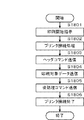
図5は、図2に示したROM207内に格納されモジュールの構成を説明するブロック図である。本例はデジタル印刷機102内のコントローラ部205により読み出され実行される各種プログラムおよび該プログラム等によって使用されるデータを例示したものである。図示するように、ROM207には本デジタル印刷機102が提供することのできる各種機能を実現するための制御プログラムが格納されている。
FIG. 5 is a block diagram for explaining the configuration of the module stored in the
図5において、ブートローダ501はデジタル印刷機102の電源投入直後に実行されるプログラムである。このブートローダ501には、システムの起動に必要となる各種起動シーケンスを実行するためのプログラムが含まれる。
In FIG. 5, a
オペレーティングシステム502は、本デジタル印刷機102の機能を実現する各種プログラムの実行環境を提供することを目的としたプログラムである。これは、主に本デジタル印刷機102のメモリ、すなわち図2におけるROM207やRAM208,ハードディスク209等の資源管理、および同図に示された各種装置の基本的な入出力制御等の機能を提供する。
The
データ送受信プログラム503は、図2における外部I/F202を経由してデータの入出力要求が発生した際に行われる送受信処理を行うための制御プログラムである。
具体的にはTCP/IP等のプロトコルスタックを内包し、ネットワーク100経由で接続される外部機器等との間で交わされる各種データの通信を執り行うための制御プログラムである。ここで、行われる通信処理は、本デジタル印刷機102と外部I/F202の間を入出力されるデータパケットの送受信レベルやHTTPサーバ等通信処理に特化した処理を担当し、この後述べる受信されたデータの内容に関する解析処理は含まれない。データの解析処理は、後述するコントローラ部205によって別プログラムの記述内容に基づいて実行される。
The data transmission /
Specifically, it is a control program that includes a protocol stack such as TCP / IP and performs communication of various data exchanged with external devices connected via the
JDF機能プログラム504は、JDFジョブデータ(印刷ジョブデータ)が外部I/F202経由で本デジタル印刷機102によって受信された場合に、外部I/F204の指示によりコントローラ部205によって実行されるプログラムである。
コントローラ部205によって行われるJDFプリント機能においては、JDF機能プログラム504に記述された処理順序、処理条件に基づいてコントローラ部205によって適切な順序で各装置の動作を順次指示する。その結果として最終的にJDFプリント処理が実行されるように制御される。
各装置には、図2におけるシート処理装置200、プリンタ部203、HDD209、圧縮展開部210、RAM208等が含まれる。また、外部I/F202経由で受信されたJDFジョブデータの解析処理および、解析処理の結果、JDFに誤った設定が含まれるか否かの判別処理、及び誤った設定を解消するための設定変更等を行うプログラムも含まれる。
The
In the JDF print function performed by the
Each apparatus includes the
コピー機能プログラム505は、操作部204経由で本デジタル印刷機102のユーザがコピーファンクションの実行を指示した際に前記操作部204からの指示によりコントローラ部205によって実行されるコピー機能を実行するためのプログラムである。
A
コントローラ部205によって行われるコピー機能においては、本デジタル印刷機102内の資源を本プログラムに記述された処理順序、処理条件に基づいてコントローラ部205によって適切な順序でこれら各装置の動作を順次指示する。それにより最終的にコピー処理が実行されるように制御される。前述の各装置には、スキャナ部201やプリンタ部203、シート処理装置200、HDD209、圧縮展開部210、RAM208等が含まれる。
In the copy function performed by the
スキャン機能プログラム506は、操作部204経由で本デジタル印刷機102のユーザがスキャンファンクションの実行を指示した際に、操作部204からの指示によりコントローラ部205によって実行されるスキャン機能を実行するためのプログラムである。コントローラ部205によって行われるスキャン機能は次のように実行される。
スキャナ部201、HDD209、圧縮展開部210、RAM208等のモジュールが、本デジタル印刷機102内の資源を本プログラムに記述された処理順序、処理条件に基づいてコントローラ部205によって制御される。その際に、適切な順序でこれら各装置の動作を順次指示することにより最終的にスキャン処理が実行されるように制御される。
A
Modules such as the
PDLプリント機能プログラム507は、PDLジョブデータ(印刷ジョブデータ)が外部I/F202経由で本デジタル印刷機102によって受信された場合に、外部I/F204の指示によりコントローラ部205によって実行されるプログラムである。コントローラ部205によって行われるPDLプリント機能においては、本プログラムに記述された処理順序、処理条件に基づいてコントローラ部205によって適切な順序で各装置の動作を順次指示する。その結果として最終的にPDLプリント処理が実行されるように制御される。前記各装置には、シート処理装置200、プリンタ部203、HDD209、圧縮展開部210、RAM208等が含まれる。
The PDL
BOX機能プログラム508は、操作部204経由で本デジタル印刷機102のユーザがBOXファンクションの実行を指示した際に、前記操作部204からの指示によりコントローラ部205によって実行されるBOX機能を実行するプログラムである。
BOX機能においては、本デジタル印刷機102を本プログラムに記述された処理順序、処理条件に基づいてコントローラ部205によって適切な順序でこれら各装置の動作を順次指示することによりBOX処理が実行されるように制御される。各装置には、スキャナ部201やプリンタ部203、シート処理装置200、HDD209、圧縮展開部210、RAM208等が含まれる。格納されたジョブデータに対して、格納時の設定を変更して実行することが可能である。
The
In the BOX function, the BOX processing is executed by sequentially instructing the operation of each device in an appropriate order by the
UI制御プログラム509は、図2において示した操作部204の制御用プログラムである。UI制御プログラム509は、本デジタル印刷機102のユーザによる操作部204の入力された内容を識別し適切な画面遷移及びコントローラ部205に対する処理依頼指示を行う。
The
シート管理プログラム510は、本デジタル印刷機102が利用可能なシートに関連する管理機能を実行するためのプログラムである。当該プログラムによって管理されるシート関連情報は、該プログラムの処理によってHDD209上に格納される。
A
その他の制御プログラム511は、上述したプログラムのいずれにも該当しない機能を実現するためのプログラムのことであり、種々の作がこれに含まれるが本実施形態の効果を説明する限りに置いてその詳細は重要ではないため、説明は省略する。512は空き領域である。
The
なお、本実施形態における同図に置いて示した各種機能プログラムにおいては、その全てを備える必要はなく、その一部あるいは前述した以外の機能プログラムを備える構成であっても構わない。いずれの場合に置いても、本発明が有効である。 It should be noted that the various function programs shown in the figure in the present embodiment do not need to be provided with all of them, and may be configured with a part of them or a function program other than those described above. In any case, the present invention is effective.
図6は、図1に示したコンピュータ101が実行するモジュールの構成を示す図である。本例は、図1に示したコンピュータ101におけるHDD311内に格納され、CPU301によって読み出され実行される各種プログラム例である。
図6において、ブートローダ601およびオペレーティングシステム602の動作は図5における印刷装置のブートローダ501およびオペレーティングシステム502と同等のため説明は省略する。
FIG. 6 is a diagram showing the configuration of modules executed by the
In FIG. 6, the operations of the
デバイスドライバ603は、コンピュータ101に接続される各種ハードウェアを制御するためのプログラムである。KBC305、CRTC306、DKC307等を制御するためのプログラムも含まれる。
The
印刷アプリケーションプログラム604は、コンピュータ上で動作し、PODシステムユーザに各種機能やサービスを提供することを目的としたプログラムの総称である。印刷アプリケーションプログラム604は、印刷ジョブデータを作成もしくは編集する機能を有する。また、印刷アプリケーションプログラム604は、該アプリケーションの図示しない設定画面より設定された各種印刷仕様から対応する印刷設定に変換する機能を持つ。
さらに、該アプリケーションは逆に印刷設定に含まれる設定から対応する印刷アプリケーションプログラム604の設定画面の表示項目を制御するために必要な内部情報に変換することも可能である。
さらに、印刷アプリケーションプログラム604は、HDD311内に保存されている印刷設定ファイルを選択し、印刷ジョブデータを作成する機能も有する。該印刷アプリケーションプログラム604は前期印刷設定として、PDLコマンド形式若しくはJDF形式に変換し、印刷対象データと合成して印刷ジョブデータを作成する能力を有する。
The
Further, the application can also convert the settings included in the print settings into internal information necessary for controlling display items on the setting screen of the corresponding
Further, the
ネットワーク制御プログラム605は、前記印刷アプリケーションプログラム604によって作成された印刷ジョブデータをネットワーク100により接続されるデジタル印刷機102に対し、印刷ジョブを送信する際に実行されるプログラムである。
ネットワーク制御プログラム605は、印刷データの送信、送信後は印刷処理の進捗を該コンピュータ101に接続されたデジタル印刷機102により実行される印刷ジョブの進捗情報を取得するなどの機能をも有するよう構成可能である。その他のプログラム607は、上記のいずれにも該当しない全てのプログラム群が含まれるが詳細な説明は省略する。
The
The
図7は、図3に示したCRT310に表示されるユーザインタフェースの一例を示す図である。本例は、図6において示した、印刷アプリケーションプログラム604を図3におけるCPU301による制御のもとCRT310上に表示される、アプリケーション画面701の一例を示したものである。以下、該アプリケーションの画面に表示される各部の仕様および関連する機能について説明する。
FIG. 7 is a diagram showing an example of a user interface displayed on the
図7において、メニューバー702は、該印刷アプリケーションが所有する各種設定、機能を選択するための表示部である。本実施形態におけるアプリケーションにおいては、プルダウンメニュー形式でさらなる詳細な項目の選択が可能なよう構成されている。メニューバー702およびそこから選択可能なプルダウンメニューの機能については後述する。
In FIG. 7, a
703は印刷対象データ一覧を示す画面領域である。当該領域の上部には、各印刷対象データの情報や設定を示すための領域が存在する。具体的には、ジョブ番号704、ファイル名称705、ジョブオーナー706、ページ数707、部数708、配送先709、仕分け710の各情報が区分され表示される。
ジョブ番号704は、当該印刷アプリケーションに印刷対象となる印刷対象データが登録された順にユニークに割り振られるID情報である。印刷対象データを管理する際に利用されるが、本発明における実施形態の説明においては本質的ではないため省略する。
ファイル名称705は、印刷対象となる印刷対象データのファイル名称を表示するための領域である。当該印刷アプリケーションのユーザが印刷対象データの識別を容易とすることを目的とする。
The
A
ジョブオーナー706は、当該印刷アプリケーションに対して印刷対象データの登録処理、すなわち印刷処理手続きを実施したユーザに関する情報を表示する領域である。本発明における本実施形態においては、複数のユーザによって印刷対象データが一時的に登録され、後のタイミング一斉に印刷処理を行うという、ジョブホールドの形態を例としている。
そのため、複数のユーザが任意のタイミングで印刷対象データの登録を実施することが想定されうることを考慮し、登録された印刷対象データ管理を容易とするための利便性向上目的として当該印刷対象データの表示欄を設けた。
単一ユーザのみによる印刷対象データ登録管理、もしくは複数のオペレータが存在する場合においてもそれらオペレータの区別が不要となるユースケースにおいては、当該表示欄は不要となるよう印刷アプリケーションを構成しても構わない。
The
Therefore, considering that a plurality of users can register the print target data at an arbitrary timing, the print target data is used for the purpose of improving the convenience of managing the registered print target data. The display column was provided.
In a use case where only one user needs to register data to be printed or use cases where there is no need to distinguish between operators even when there are multiple operators, the print application may be configured so that the display field is not necessary. Absent.
ページ数707は、当該印刷アプリケーションに登録された各印刷対象データに含まれる印刷対象ページ数を表示するために設けられた領域である。ここに表示される情報は当該印刷アプリケーションが所有する機能によって、印刷対象データの登録時に登録されたデータを解析する事によって得られるよう構成される。
The
部数708は、当該印刷アプリケーションに登録された各印刷対象データに対して印刷時に指定される印刷仕様のうち、部数に関する情報を表示するための領域である。印刷対象データ登録時の印刷仕様の設定手段については後述する。
The number of
配送先709は、当該印刷アプリケーションに登録された各印刷対象データの配送先に関する情報を表示するためのものである。なお、配送先情報によって、後の印刷処理時において仕分け処理を実施する際に当該情報は利用されることを目的としている。すなわち、当該印刷アプリケーションは、既述の如く、複数の印刷対象データを当該印刷アプリケーションに蓄積し、後のタイミングで一斉に印刷ジョブデータに変換し印刷処理する。その印刷ジョブデータの印刷処理時に、当該配送先709欄によって示される情報に基づいた単位で仕分け処理が実施されるよう制御する。 The delivery destination 709 is for displaying information related to the delivery destination of each print target data registered in the print application. The delivery destination information is intended to be used when performing the sorting process in the subsequent printing process. That is, as described above, the print application accumulates a plurality of print target data in the print application, and simultaneously converts the print target data into print job data at a later timing and performs print processing. At the time of the print processing of the print job data, control is performed so that the sorting process is performed in units based on the information indicated by the delivery destination 709 field.
換言すれば、同一配送先の情報を有する印刷対象データを連続的にひとかたまりとして印刷および仕分け処理を実施することにより、印刷処理実行後の成果物を仕分け単位である配送先毎の成果物をブロック単位に分割することを容易とする。
配送先709は、その際の仕分け処理を実現するための印刷ジョブデータを構成する際に利用することを目的として設けられた情報である。配送先単位での仕分け処理が印刷時に実施されることにより、複数の種類の異なる印刷対象データを如何なる順序によって当該印刷アプリケーションに登録した場合においても、配送先毎に出力物のブロックを分離することを容易にすることが可能となる。すなわち、オペレータによる仕分けミスによって誤配送が発生するという課題を解消しうるのである。
In other words, the printing target data having the same delivery destination information is continuously printed as a group, and the printing and sorting process is performed, thereby blocking the deliverables for each delivery destination as the sorting unit. It is easy to divide into units.
The delivery destination 709 is information provided for the purpose of using the print job data for realizing the sorting process at that time. By performing sorting processing in units of delivery destinations at the time of printing, even if multiple types of different print target data are registered in the printing application in any order, the blocks of output products are separated for each delivery destination. Can be facilitated. That is, the problem that erroneous delivery occurs due to an operator sorting error can be solved.
本実施形態では、仕分け単位として、配送先を想定した印刷アプリケーションの例を示した。しかしながら、仕分け単位は、配送先以外にも様々存在しうる。従って、配送先709によって示される情報は他の仕分け目的による単位を意味する情報に置き換えるよう構成したとしても一向に構わない。本実施形態においては、説明の便宜を意図し、配送先という課題解決の効果を容易に説明しうる情報を例として示したに過ぎない。 In this embodiment, an example of a print application that assumes a delivery destination as a sorting unit has been shown. However, there are various sort units other than the delivery destination. Therefore, the information indicated by the delivery destination 709 may be replaced with information indicating a unit for another sorting purpose. In the present embodiment, for the convenience of explanation, information that can easily explain the effect of problem solving as a delivery destination is merely shown as an example.
仕分け710は、当該欄が選択された印刷対象データに対応する印刷ジョブデータ中の対応ページの印刷開始時に、仕分け処理がなされるよう、当該印刷アプリケーションに指示するための情報を設定するために設けられたフィールドである。印刷アプリケーションは前記のような動作をするよう、印刷ジョブデータの設定情報を作成するよう構成されている。
スクロールバー712は、同図にて示す印刷アプリケーションのジョブデータ一覧画面に表示しきれない場合に表示領域を上下に移動するための制御を行うものである。総ドキュメント数711は、当該印刷アプリケーションに登録されている印刷対象データ数を表示する領域である。
The sorting 710 is provided for setting information for instructing the printing application so that sorting processing is performed when printing of the corresponding page in the print job data corresponding to the print target data with the column selected is started. Field. The print application is configured to create print job data setting information so as to perform the above-described operation.
The
なお、本実施形態では、印刷アプリケーションは図7においてその一例を示したが、同等の機能を有する他の構成もあり得る。また、同図にて表示されている各種情報のうち、いくつかあるいは全ては必ずしもアプリケーション機能として有している必要はない。すなわち、印刷対象データが、配送先情報と共に管理されており、仕分けの設定が可能なよう構成されていれば他の構成を取ったとしても構わない。
図8は、図3に示したCRT310に表示されるユーザインタフェースの一例を示す図である。本例は、図7において示したメニューバー702のうち編集メニュー801を選択した際に表示されるプルダウンメニュー機能の一例を示すためのものである。
図示する通り、各種機能が編集メニュー801のプルダウンメニュー内から選択可能であるが、ここでは主要なものについてのみ説明する。
In the present embodiment, an example of the print application is shown in FIG. 7, but there may be other configurations having equivalent functions. Also, some or all of the various types of information displayed in the figure need not necessarily have application functions. That is, as long as the print target data is managed together with the delivery destination information and can be set for sorting, another configuration may be adopted.
FIG. 8 is a diagram showing an example of a user interface displayed on the
As shown in the figure, various functions can be selected from the pull-down menu of the
設定変更メニュー802は、選択した印刷対象データのジョブの印刷設定を変更する際に選択するメニューである。本例においては、ジョブ804、すなわちジョブ番号0008のジョブが反転選択された状態である。この状態において設定変更メニュー802を選択することにより当該ジョブの登録時になされた印刷設定を変更することが可能である。
配送先順にソートメニュー803は、当該印刷アプリケーションに登録されている印刷対象データを、配送先709をキーとして、順序の入れ替え処理を実施する為のものである。
A setting change menu 802 is a menu that is selected when changing the print setting of the job of the selected print target data. In this example, the
The
データ追加メニュー805は、当該印刷アプリケーションによって印刷対象とするデータを追加するためのメニューである。印刷対象データは、データ追加メニュー805によって表示される図示しないファイル選択メニューから実行することが可能である。もしくは、当該印刷アプリケーションが動作するコンピュータ101が具備するマウスなどによってファイルを選択し、当該印刷アプリケーション画面上にドラッグアンドドロップする等して追加するように構成することも可能である。
A
印刷対象アプリケーションにおける状態が図8に示した場合において、配送先順にソートメニュー803を選択し実行した結果の状態を図9に示す。
図9は、図3に示したCRT310に表示されるユーザインタフェースの一例を示す図である。本例では、各印刷対象データが、配送先の設定に従って順序の入れ替えが処理がなされていることが確認される。すなわち、図9に示す状態において印刷処理を実行すれば、図9のジョブデータ一覧の最上位のデータから印刷処理が開始される。そのために、配送先901毎にまとまった単位で印刷データがデジタル印刷機102に送信され、また印刷処理が実行されることを意味する。
FIG. 9 shows the result of selecting and executing the
FIG. 9 is a diagram showing an example of a user interface displayed on the
図10は、図3に示したCRT310に表示されるユーザインタフェースの一例を示す図である。本例は、該印刷アプリケーションの画面表示が図9の状態の状態において、図8において示したデータ追加メニュー805の選択、もしくは前述したドラッグアンドドロップ等の操作によりデータ追加処理を実施した際の画面例である。
FIG. 10 is a view showing an example of a user interface displayed on the
図10に示す通り、追加対象となる印刷データのファイル名称1001、および当該印刷データの追加処理を実施したジョブオーナー1002が自動的に入力された状態を示している。部数1003については、当該印刷対象データを登録処理した際に設定可能なよう、当該印刷アプリケーションは構成されている。具体的には部数の増減ボタン1006によって、部数を変更することが可能である。
As shown in FIG. 10, the
配送先1004は、図7における配送先709フィールドに表示される情報の登録を行う入力欄である。本実施形態における例においては、支社Cが配送先欄1005に入力された状態について示している。
なお、配送先1004欄に入力する方法としては、図3におけるKBによって直接入力するか、もしくは同図には示さないプルダウンメニューによって予め登録された配送先の中から選択する等、各種手法が考えられる。配送先1004欄に対する配送先情報の入力手段については、本発明の本質的な条件ではないため、図10においてはKB309によって直接入力する仕様の例として示した。
この手法によれば、任意の配送先情報の入力が可能となり、仮に当該印刷データの登録処理を実施したオペレータが配送先情報の入力時に誤った文字列等を入力してしまう可能性がある。しかしながら、プルダウン形式のように、予め配送先の登録処理が不要で任意の配送先を登録できるため運用時の柔軟性が高いというメリットも存在し、一概に何れの手法が優れているとの判断は容易ではない。
The
Various methods may be used for inputting to the
According to this method, it is possible to input arbitrary delivery destination information, and there is a possibility that an operator who has performed the print data registration process inputs an incorrect character string or the like when inputting the delivery destination information. However, there is a merit that flexibility of operation is high because it is possible to register any delivery destination without registering the delivery destination in advance as in the pull-down format, and it is judged that any method is superior. Is not easy.
いずれにしても、当該配送先欄004に対する情報の入力手段は本発明の主要な要素ではなく、如何なる手法が選択された場合においても、本発明は有効である。 In any case, the information input means for the delivery destination column 004 is not a main element of the present invention, and the present invention is effective when any method is selected.
印刷設定ボタン1007は、登録対象となる印刷データを印刷処理する際の印刷仕様の設定に関する設定画面を表示させるためのボタンである。設定可能な印刷仕様としては、図1において示したデジタル印刷機102がサポートする印刷処理に指定可能な各種条件を必要に応じて指定可能な様構成される。
しかしながら、同設定画面によって指定可能な印刷設定の内容自体は本発明の効果を説明する上で、本質的ではないため、詳細は省略する。
OKボタン1008を押下することによって、当該印刷データが図7において示した当該印刷アプリケーションに登録される。すなわち、印刷対象データに追加される。
一方、キャンセルボタン1009を押下した場合には、印刷対象データは登録されることなく、図9の画面状態に遷移する。その場合、同図にて行った各種設定内容も破棄される。
A print setting button 1007 is a button for displaying a setting screen for setting print specifications when print data to be registered is printed. The print specifications that can be set are configured so that various conditions that can be specified for print processing supported by the
However, the details of the print settings that can be specified on the setting screen are not essential in describing the effects of the present invention, and thus the details are omitted.
By pressing an
On the other hand, when the cancel
図11は、図3に示したCRT310に表示されるユーザインタフェースの一例を示す図である。本例は図10において示したデータ追加画面によってOKボタン1008が押下された直後の当該印刷アプリケーションの画面の状態の例を示したものである。
図11に示す通り、図10において追加処理を実施した印刷対象データがジョブ番号1101に示す箇所に追加されていることが確認される。また、総ドキュメント数1102も追加されたデータ分が反映されていることが確認される。
図12は、図3に示したCRT310に表示されるユーザインタフェースの一例を示す図である。本例は当該印刷対象アプリケーションにおいて、図11において示した画面状態において、仕分け処理の設定を実施した後の画面状態の一例を示すためのものである。
FIG. 11 is a diagram showing an example of a user interface displayed on the
As shown in FIG. 11, it is confirmed that the print target data subjected to the addition process in FIG. 10 is added to the location indicated by the
FIG. 12 is a diagram showing an example of a user interface displayed on the
図12では、チェックマーク1201、1202が付加されている状態が確認される。これは、チェックマーク1201、1202が付与された箇所において、当該印刷アプリケーションに登録されている印刷データのページの印刷処理時に、仕分け処理が実施されるように印刷ジョブデータを構成するよう印刷仕様の設定を指示している処理に該当する。
図12において示されるように、支社Aおよび支社Bの境界に相当する印刷対象データ、および支社Bおよび支社Cの境界に相当する印刷対象データに仕分け処理の指示がなされている。このように設定する事により、当該印刷アプリケーションがデジタル印刷機102に印刷ジョブデータを送信し印刷処理する際に、支社Bおよび支社C用の出力物の印刷開始時に仕分け処理がなされることとなる。
In FIG. 12, a state in which
As shown in FIG. 12, an instruction for the sorting process is given to the print target data corresponding to the boundary between the branch offices A and B and the print target data corresponding to the boundary between the branch offices B and C. By setting in this way, when the printing application transmits print job data to the
なお、図12における仕分けのチェックマークは、図3において示すコンピュータ101が具備する図示しないマウス等のポインティングデバイスにより実施されることを想定しているが、他の手段によって選択される様に構成してももちろん構わない。
12 is assumed to be performed by a pointing device such as a mouse (not shown) provided in the
図13は、図3に示したCRT310に表示されるユーザインタフェースの一例を示す図である。本例は、当該印刷アプリケーションによって、デジタル印刷機102に対し登録された印刷対象データを印刷ジョブデータに変換した上で送信し印刷処理を実施する際の指示手段の一例を示すためのものである。
FIG. 13 is a diagram showing an example of a user interface displayed on the
当該印刷アプリケーションによって印刷開始を指示する際には、図7におけるメニューバー702のファイルメニュー1301によって選択可能なプリントメニュー1302によって実施されるよう構成されている。
When the print application is instructed to start printing, the print menu 1302 that can be selected by the file menu 1301 of the
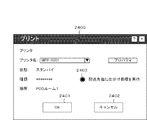
図14は、図3に示したCRT310に表示されるユーザインタフェースの一例を示す図である。本例は、図13において示したプリントメニュー1302を選択した後に表示される印刷開始を指示するプリント画面の一例を示したものである。各種情報が記載されているが重要な部分に限定し以下説明を行う。
FIG. 14 is a diagram showing an example of a user interface displayed on the
図14において、プリンタ名1403は、印刷する際に使用するデジタル印刷機102を選択するためのものである。複数のデジタル印刷機102が当該印刷アプリケーションが動作するコンピュータ101にネットワーク100経由で接続されている場合に、特定のデジタル印刷機102を指定する際に使用することを想定し設けられた機能である。複数のデジタル印刷機102はプルダウンメニューによって予め登録されているプリンタの中から選択可能なよう構成されている。
In FIG. 14, a
プロパティ1404は、当該印刷アプリケーションに登録されている印刷対象データを印刷ジョブデータに変換する際に、行う各種印刷仕様の設定やデジタル印刷機102に対する動作指示に関する仕様を設定する画面表示のためのものである。ここで指定可能な印刷仕様の項目は各種存在するが、本発明本実施形態においては仕分け処理以外の印刷仕様の設定に関しては効果の説明において重要ではない。
仕分け処理の設定について、当該印刷アプリケーションはプロパティ1404ではなく図7において示した仕分け710フィールドにて指定可能な様構成されており、図13にて示した状態に設定されている。従って、プロパティ1404を押下することによって表示される印刷仕様設定画面の詳細説明は省略する。
A
Regarding the setting of the sorting process, the print application is configured to be specified in the sorting 710 field shown in FIG. 7 instead of the
OKボタン1401を押下することにより、当該印刷アプリケーションによる印刷処理が開始される。また、キャンセルボタン1402を押下することにより、印刷処理の指示を中止し、図12相当の画面に遷移するよう制御される。 By pressing an OK button 1401, printing processing by the printing application is started. Further, when a cancel button 1402 is pressed, the print processing instruction is stopped, and control is performed so as to shift to a screen corresponding to FIG.
図15は、本実施形態を示す印刷装置で扱う印刷ジョブデータの構成を説明する図である。本例は、当該印刷アプリケーションにおいて登録された印刷対象データが図13の状態にある際に、図14におけるOKボタンを押下された後に生成される、印刷ジョブデータの構成例である。
本実施形態においては、印刷ジョブデータ1500全体は、単一のPDLストリームデータとして構成される場合を例として示す。すなわち、当該印刷アプリケーションにおいては図7およびそれ以降の図において示した通り、印刷対象データは個別に登録および管理されている。しかしながら、印刷処理を指示し実行した際にはそれら各印刷対象データをPDLデータに変換すると共に、各印刷対象データに対応するPDLデータを連結した単一のデータを構成するよう制御される。
FIG. 15 is a diagram illustrating the configuration of print job data handled by the printing apparatus according to the present embodiment. This example is a configuration example of print job data generated after the OK button in FIG. 14 is pressed when the print target data registered in the print application is in the state shown in FIG.
In the present embodiment, the case where the entire print job data 1500 is configured as a single PDL stream data is shown as an example. That is, in the printing application, as shown in FIG. 7 and subsequent drawings, the print target data is individually registered and managed. However, when the print processing is instructed and executed, each print target data is converted into PDL data, and at the same time, control is performed so as to form a single data concatenating the PDL data corresponding to each print target data.
これは、トランザクションジョブと言われるPOD(Print On Demand)ユースケースにおいて多用されるデータの形成方法を当該印刷アプリケーションが採用したことに起因するためである。トランザクションジョブは、他にもVDP(バリアブルデータプリント)など、大量のページを連続的にプリンタに対し送信し逐次処理するユースケースに適した手法である。 This is because the printing application adopts a data forming method frequently used in a POD (Print On Demand) use case called a transaction job. The transaction job is a technique suitable for a use case such as VDP (variable data printing), in which a large number of pages are continuously transmitted to a printer and sequentially processed.
図15において、ストリームデータは、図における右側がデータの先頭位置に該当し、一方左側がデータの末尾に該当する。連続したPDLジョブデータであるストリームデータ中における、返還前の印刷対象データとの関連性を明確にするため、同図において元となった印刷対象データのファイル名を同図に対応づけて記載している。
すなわち、各ファイル名称の印刷対象データ1501、1502、1503、1504、1505、1506、1507、1508、1509がこれらに相当する。
このストリームデータ中における元となる印刷対象データの並び順は図12において示した印刷アプリケーションに登録されている印刷対象データの順序と一致している点が重要である。すなわち、当該印刷対象データは図12において示された印刷対象データの順序に従い、図15において示したPDLストリームデータを形成するよう制御する。
In FIG. 15, in the stream data, the right side in the figure corresponds to the head position of the data, while the left side corresponds to the end of the data. In order to clarify the relationship with the print target data before return in the stream data that is continuous PDL job data, the file name of the original print target data in FIG. ing.
That is, the
It is important that the arrangement order of the original print target data in the stream data matches the order of the print target data registered in the print application shown in FIG. That is, the print target data is controlled to form the PDL stream data shown in FIG. 15 according to the order of the print target data shown in FIG.
図15において、上述した各印刷対象データに対応するPDLデータとは別のデータが前記PDLストリームデータには含まれている。
ヘッダ1510は、ヘッダと呼ばれ、デジタル印刷機が印刷処理を実行する際の前処理や初期化処理等を行う際に必要に応じて追加されるデータである。これら処理が不要な場合にはヘッダ1510は省略することも可能である。また、使用するPDLデータの種別によってもヘッダ1510が必要なものと不要なものが存在する。同図においてはこれらヘッダ1510が必要であった場合を想定した例を示した。しかしながら、ヘッダ1510に記載される指示情報の内容は本発明本実施形態の効果を説明する上で重要ではないため、説明を省略する。
In FIG. 15, the PDL stream data includes data different from the PDL data corresponding to each print target data described above.
The
1511は、ヘッダ同様の目的を持った設定を格納する領域である。ただし、こちらは後処理を目的とする点が異なる。いずれにしても、ヘッダ1510と同様、不要な場合には本領域は省略可能であるが、図15においては、この情報が必要であった場合を想定した例を示した。
しかしながら、ここに記載される指示情報の内容は本発明本実施形態の効果を説明する上で重要ではないため、説明を省略する。
However, since the contents of the instruction information described here are not important for explaining the effect of the present embodiment of the present invention, the explanation is omitted.
1512および1513は仕分け処理コマンドである。これら仕分けコマンドがストリームデータ中に挿入された位置が重要であるすなわち、F(1503とG(1504)の間および、H(1505)とI(1506)の間である。すなわち、図12にて示した配送先毎の仕分け単位の位置と一致するように、仕分けコマンドが挿入されていることが確認される。
当該印刷ジョブデータ1500をデジタル印刷機102が受信し処理した際に、仕分けコマンドが挿入された位置でデジタル印刷機102の排紙機構が備える仕分け装置によって仕分け処理が実施されるよう、印刷アプリケーションがストリームデータを構成する。
図16は、図15における仕分けコマンド1512の詳細構成を示す図である。
図16において、上方がストリームデータの先頭方向、下方が末尾方向を意味する。
When the
FIG. 16 is a diagram showing a detailed configuration of the
In FIG. 16, the upper direction means the head direction of the stream data, and the lower side means the end direction.
デジタル印刷機から印刷アプリケーションの機能によって変換されたPDLデータF(1503)、G(1504)、H(1505)の部分に着目して記載している。その前後の箇所は同図においては省略されている。 The description is focused on the PDL data F (1503), G (1504), and H (1505) converted from the digital printing machine by the function of the printing application. The parts before and after that are omitted in the figure.
図16におけるF(1503)およびG(1504)の間に仕分けコマンド1512が挿入されている状況を表わしている。仕分けコマンドの一例を同図において示しているが、あくまでも一例にすぎず、実際にはPDLデータの種別およびデジタル印刷機102が解釈および処理可能な仕分けコマンドの仕様に依存する。
デジタル印刷機102は、PDLプリント機能プログラム507が受信した当該ストリームデータの先頭から処理を実施する過程で、図16に示す仕分けコマンドを含む各仕分けコマンド(図15参照)を認識し解釈する。そして、その段階で、デジタル印刷機102は、指示された仕分け処理を実施するよう制御するよう構成されている。デジタル印刷機102における仕分け処理の詳細については後述する。
FIG. 16 illustrates a situation in which a
The
図17は、図15、図16において示した、印刷アプリケーションがデジタル印刷機102に対して送信する印刷ジョブデータを受信し、印刷および仕分け処理を実施した後のデジタル印刷機の排紙装置の状態を説明する図である。
図17において、排紙トレイ1701とは、図2において示した大容量スタッカ225、226もしくは中綴じ製本機227が備える通常排出トレイの何れかに相当する。
FIG. 17 shows the state of the paper discharge device of the digital printing machine after receiving the print job data transmitted from the printing application to the
In FIG. 17, the paper discharge tray 1701 corresponds to either the
図17に示す通り、排紙トレイ1701上に、複数の出力シートが仕分けされた状態でスタックされていることが同図から確認される。本発明における本実施形態における仕分け処理はシフト排紙の場合を例として示した。 As shown in FIG. 17, it can be confirmed from FIG. 17 that a plurality of output sheets are stacked on the paper discharge tray 1701 in a sorted state. The sorting process according to the present embodiment of the present invention is illustrated by taking the case of shift sheet discharge as an example.
出力シート束1702は、配送先が支社Aである印刷対象データD、E、Fによる出力物に相当する。出力シート束1703は、配送先が支社Bである印刷対象データG,Hによる出力物に相当する。同様に、出力シート束1704は、配送先が支社Cである印刷対象データI、J、K、Lによる出力物に相当する。
The output sheet bundle 1702 corresponds to an output product by print target data D, E, and F whose delivery destination is the branch office A. The output sheet bundle 1703 corresponds to an output product based on the print target data G and H whose delivery destination is the branch office B. Similarly, the
このように、結果的に指定した配送先毎にスタックおよびシフト排紙(仕分け処理)されてデジタル印刷機102の排紙装置にスタックされることによって、配送先毎の仕分け作業が容易となる。結果的に、オペレータの負荷を低減する効果が得られると同時に、仕分け時のミスによるご配送のリスクを低減する効果をも得られるのである。
なお、コントローラ部205は、同一の仕分け装置上でシート束(出力シート束)の配置位置を変更して排紙させる他に、以下のように区切りが明確となる排紙方法を採用することができる。
コントローラ部205は、複数の仕分け装置を配送先に割り当ててシート束(出力シート束)を排紙させたり、同一の仕分け装置上で同一位置に排紙されるシート束に区切りシートを挿入して排紙させる等が好例である。
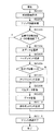
図18は、本実施形態を示す情報処理装置の制御方法を説明するフローチャートである。本例に示す印刷処理例である。なお、各ステップは、コンピュータ101上のCPU301によって実行される印刷アプリケーションプログラム604を実行することにより実現される。
Thus, as a result, stacking and shift discharge (sorting process) are performed for each designated delivery destination and stacked on the paper discharge device of the
Note that the
The
FIG. 18 is a flowchart illustrating a method for controlling the information processing apparatus according to the present embodiment. It is a print processing example shown in this example. Each step is realized by executing a
コンピュータ101上の印刷アプリケーションプログラム604による印刷処理は、図13において示したプリントメニュー1302が選択操作されたことを契機に開始される(S1801)。
Printing processing by the
次に、S1802に進み、CPU301は、印刷処理で使用するネットワーク100を経由し接続されているデジタル印刷機102との接続を確立する。具体的には、コンピュータ101が具備するNC312と、デジタル印刷機102が具備する外部I/F202との間のコネクションを確立しデータ送信の準備を行う。
In step S1802, the
S1803において、S1802の実行によって確立されたコンピュータ101およびデジタル印刷機102間のコネクションを通じてヘッダコマンドをコンピュータ101がデジタル印刷機102に対して送信する。
なお、S1803において、デジタル印刷機102に送信される情報は、図15において示したヘッダ1510によってあらわされる、ストリームデータの先頭部に相当する情報である。
In step S <b> 1803, the
In S1803, the information transmitted to the
次に、S1804では、CPU301が印刷対象データをデジタル印刷機102に送信する。なお、S1804において送信される情報は図15における例では次の符号によって表現されるものが相当する。すなわち1501、1502、1503、1512、1504、1505、1513、1506、1507、1508、1509である。S1804における処理の詳細は後述する。
In step S <b> 1804, the
そして、S1804の処理が終わったら、S1805に進み、CPU301は、図15における領域1511によってあらわされる情報をコンピュータ101がデジタル印刷機102に対して送信する。S1805において送信される情報は、図15において示したヘッダ1510によって表される、ストリームデータの末尾部に相当する情報である。
When the processing of S1804 is completed, the process advances to S1805, and the
最後にS1806にて、CPU301は、S1802にてデジタル印刷機102との間で確立したコネクションを断絶(接続を終了)し、印刷処理を終了する。
Finally, in S1806, the
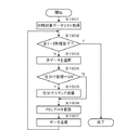
図19は、本実施形態を示す情報処理装置の制御方法を説明するフローチャートである。本例は、図18に示したS1804の処理、すなわち印刷対象データ送信処理の詳細処理例である。なお、各ステップは、図18において示したフロー図と同様、コンピュータ101上のCPU301によって実行される印刷アプリケーションプログラム604が実行されることによって実現される。
FIG. 19 is a flowchart illustrating a method for controlling the information processing apparatus according to the present embodiment. This example is a detailed processing example of the processing of S1804 shown in FIG. 18, that is, the print target data transmission processing. Each step is realized by executing a
まず、CPU301は、最初に印刷対象データのリストを取得する(S1901)。S1901における処理は、印刷アプリケーションに登録されたジョブリスト703に表示された印刷対象データを、表示順となるよう作成されたリストを取得する処理に相当する。すなわち、当該印刷アプリケーションは、S1901において取得された順序で、印刷対象データを印刷ジョブデータに変換する処理を実施する。そのためにS1901において取得したリストが利用される。S1902以降の処理は、S1901にて取得されたリストの要素各々について実施される。
First, the
S1902では、CPU301は、印刷データ作成および送信処理が、S1901にて取得されたリストに含まれる印刷対象データの全てについて実行されたか否かを判断する。ここで、取得されたリストに含まれる印刷対象データの全てについて実行されたとCPU301が判断した場合、全データについて処理が終了した事を意味する為、同フロー図において示された処理を終了する。
In step S1902, the
一方、S1902で、取得されたリストに含まれる印刷対象データの全てについて実行されていないとCPU301が判断した場合、まだ処理が完了していない印刷対象データが残っていることを意味する。この場合には継続し処理を実行するため、S1903に進む。
そして、S1903においては、S1901にて取得したリスト中から、まだ処理未実施のデータをリストの順序に従い選択および取得する。
On the other hand, if the
In S1903, data that has not yet been processed is selected and acquired from the list acquired in S1901 according to the order of the list.
次に、S1904においては、CPU301がS1903において取得された印刷対象データ対して、仕分け処理の設定がなされているか否かを判別する。なお、本仕分け処理の設定は図12において示した通りである。
Next, in step S1904, the
ここで、CPU301が取得された印刷対象データ対して、仕分け処理の設定がなされていると判断した場合、仕分け処理を行う為のコマンドをコンピュータ101からデジタル印刷機102に対して送信する(S1905)。
一方、S1904において、取得された印刷対象データ対して、仕分け処理の設定がなされていないとCPU301が判断した場合、仕分けコマンドの送信は不要であるため、S1905の処理をスキップして、S1906に進む。
If the
On the other hand, if the
S1906では、CPU301は、S1903にて選択された印刷対象データを印刷ジョブデータに変換する処理を実施する。S1906にて変換されるPDLデータの種別は任意である。すなわち、如何なるコマンドあるいはデータフォーマットが選択された場合においても本発明は有効である。
In step S1906, the
次に、S1907では、CPU301がS1906にて作成および変換されたデータをコンピュータ101がデジタル印刷機102に送信する処理を実行して、当該送信処理が終了したら、再びS1902に戻る。
なお、S1902からS1906までの処理はループになっており、S1901にて取得されたリストの全ての要素について処理が終了するまで繰り返し実行される。
In step S1907, the
Note that the processing from S1902 to S1906 is a loop, and is repeatedly executed until the processing is completed for all elements of the list acquired in S1901.
また、S1906の印刷ジョブデータ変換処理と、S1907におけるデータの送信処理は別ステップとして同図に示すフローにおいて説明した。しかしながら、この2つのステップは並行して処理するよう構成しても構わない。すなわち、データの変換処理を実行しながら、変換が完了したデータをストリームとして逐次送信するようにすればよい。その場合、S1906とS1907は並列的に処理される。 Also, the print job data conversion process in S1906 and the data transmission process in S1907 have been described as separate steps in the flow shown in FIG. However, these two steps may be configured to be processed in parallel. That is, it is only necessary to sequentially transmit the converted data as a stream while executing the data conversion process. In that case, S1906 and S1907 are processed in parallel.
図20は、本実施形態を示す印刷装置の制御方法を説明するフローチャートである。本例は、デジタル印刷機102が、図18、図19において示したコンピュータ101上で作成される印刷ジョブデータを受信した際の当該印刷ジョブデータの印刷処理例である。なお、各ステップにおける各処理は、デジタル印刷機102におけるコントローラ部205によって実行されるPDLプリント機能プログラムが実行されることによって実現される。
FIG. 20 is a flowchart for explaining a control method of the printing apparatus according to the present embodiment. This example is a print processing example of print job data when the
S2001では、コントローラ部205は、ネットワーク100経由で接続されるコンピュータ101からの接続要求を受信しコネクションを確立する。ここで、コンピュータ101からの接続要求とは、図18において示したS1801の処理に相当する。
In step S2001, the
コンピュータ101とデジタル印刷機102のコネクションが確立されたら、S2002に進み、コントローラ部205は、コンピュータ101から送信される印刷ジョブデータを受信する。
S2003以降は、S2002にて受信される印刷ジョブデータの全てについて処理を繰り返すためのループ処理を形成する。
When the connection between the
After S2003, a loop process for repeating the process for all the print job data received in S2002 is formed.
S2003にて、コントローラ部205は、まだコネクション経由で送信されてくる処理対象データ、すなわち印刷ジョブデータのうち、未処理のデータ(未実行コマンド)があるかどうかを判別する。
ここで、未処理のデータがあるとコントローラ部205が判断した場合、まだ処理対象データが残っていると判断して、S2004以降の処理を実施する。
In step S2003, the
Here, when the
一方、未処理のデータがないとコントローラ部205が判断した場合、全印刷ジョブデータについて処理が完了した判断して、S2009に進み、コンピュータ101との間で確率しているコネクションを切断し、印刷処理を終了する。
On the other hand, if the
なお、印刷ジョブデータは、描画コマンド、印刷機の後処理等の指定を行う制御コマンド、およびそれらコマンドが処理対象とするデータから構成される。ここでは、一様にこれらをコマンドと表現し以降説明を行う。つまり、印刷ジョブデータとは、コマンドの集合と言い換えることが可能である。 Note that the print job data includes a drawing command, a control command for specifying post-processing of the printing press, and data to be processed by these commands. Here, these are uniformly expressed as commands and will be described below. That is, the print job data can be restated as a set of commands.
次に、S2004では、コントローラ部205が印刷処理対象である印刷ジョブデータを形成するストリームから次の処理対象コマンドを取得し、S2005において、コントローラ部205がその解析処理を実行する。
In step S2004, the
次に、S2006において、コントローラ部205がS2005における解析の結果、処理対象コマンドの種別が仕分けコマンドを検出したか否かを判別する。
Next, in S2006, the
ここで、コントローラ部205が処理対象コマンドの種別が仕分けコマンドを検出したと判断した場合、S2007に進み、指定した仕分け処理を実行する。S2007において実施される仕分け処理の詳細については、本発明における本実施形態においては図17において示したシフト処理による仕分けである。すなわち、コントローラ部205は、直前に排紙された出力物の排紙位置とは異なる排紙位置に、排紙位置をシフトして、出力物を排紙するよう制御する。排紙位置のシフトは、5mmであっても10mmであってもよく、ユーザが、出力物の区切れ目を見てわかればよい。なお、ユーザが、予めシフトの量を設定し、コントローラ部205は、それに従ってソフト排紙処理を行ってもよい。
If the
すなわち、S2007における仕分け処理の実行は、コントローラ部205がシート処理装置200のうちの排紙装置に対し、排紙位置をシフトするよう変更するためのコマンドを送信し排紙装置が当該コマンドを実行する処理に該当する。ここで、コントローラ部205から排紙装置に対して送信されるコマンドの詳細については省略する。
以降、再びデジタル印刷機がシフトコマンドを受信し実行しない限り、排紙装置の排紙位置は変わらない。換言すれば、次にシフトコマンドを受信した時点において、再びシフト処理が実行される。
That is, in the execution of the sorting process in S2007, the
Thereafter, unless the digital printing machine receives and executes the shift command again, the paper discharge position of the paper discharge device does not change. In other words, the shift process is executed again when the next shift command is received.
一方、コントローラ部205が処理対象コマンドの種別が仕分けコマンドを検出していないと判断した場合、コントローラ部205が判断した仕分け処理以外のコマンドを実行する(S2008)。例えば、コントローラ部205は、印刷ジョブデータに基づいて、プリンタ部203によって画像をシートに印刷させ、当該シートを排紙させる。
S2007若しくはS2008が終了したらS2002に戻り、コントローラ部205が次のコマンド処理の実行を行う。以上がデジタル印刷機102における印刷処理時の動作である。
このように、コントローラ部205はユーザが指定した任意の印刷対象データの出力物を、直前に排紙された出力物とはずれた状態で排紙するよう制御し、それ以外の印刷対象データの出力物は、直前に排紙された出力物とはずれた状態で排紙するよう制御しない。
これにより、どのドキュメントがどの配送先用のものであるのかを仕分け処理する負担が軽減され、オペレータは正しく配送先毎に仕分け処理された出力束を認識でき、配送先の誤認を確実に防止できる。
〔第2実施形態〕
On the other hand, when the
When S2007 or S2008 ends, the process returns to S2002, and the
As described above, the
This reduces the burden of sorting which document is for which delivery destination, allowing the operator to recognize the output bundle that has been sorted correctly for each delivery destination, and reliably preventing delivery destination misidentification. .
[Second Embodiment]
上記第1実施形態では、印刷アプリケーションは印刷対象データから印刷ジョブデータを作成する際に、単一の印刷ジョブデータを作成するトランザクションプリントのユースケースの例として説明した。すなわち、図15に示した通り、印刷ジョブデータは単一のストリームとして扱われ、デジタル印刷機102としては単一のジョブとして認識および処理を実行する。第2実施形態では、印刷アプリケーションがトランザクションプリントではなく、印刷ジョブを生成し、印刷ジョブのヘッダ情報に仕分けコマンドを埋め込んで仕分けさせる例について説明する。
図21は、本実施形態を示す印刷装置で処理する印刷ジョブデータの構成を説明する図である。本例は、印刷アプリケーションによって作成される印刷ジョブデータの構成について説明するためのものである。
In the first embodiment, the print application has been described as an example of a transaction print use case in which single print job data is created when print job data is created from print target data. That is, as shown in FIG. 15, the print job data is handled as a single stream, and the
FIG. 21 is a diagram illustrating the configuration of print job data processed by the printing apparatus according to the present embodiment. This example is for explaining the configuration of print job data created by a print application.
図21では、印刷ジョブヘッダ2101は、仕分けコマンドを含んで構成される。2102は印刷ジョブデータで、仕分けコマンドを含まない例である。
In FIG. 21, the
双方のケースについて、共に、デジタル印刷機が印刷処理を実行する際の前処理や初期化処理等を行う際に必要に応じて追加されるヘッダ2103、2107が含まれる。図15におけるヘッダ1510に相当する。
In both cases,
同様に、印刷対象となるコマンドやデータ本体であるPDLデータ部(2105、2108)が含まれる。図15における符号1501、1502、1503、1504、1505、1506、1507、1508、1509に相当する。
同様に、後処理コマンド(2106、2109)が含まれる。図15における符号1511によって示されるデータに相当する。
2104は仕分けコマンドである。図15における符号1512によって示されるデータに相当する。
Similarly, a command to be printed and a PDL data portion (2105, 2108) which is a data body are included. This corresponds to reference
Similarly, post-processing commands (2106, 2109) are included. This corresponds to the data indicated by
図22は、本実施形態を示す情報処理装置におけるデータ処理方法を説明するフローチャートである。本例は、コンピュータ101上のCPU301によって印刷アプリケーションプログラム604が実行されることによって行われる処理の例である。なお、以降の説明において、第2実施形態における印刷アプリケーションが第1実施形態において示した図面と共通の機能を有する場合には、第1実施形態における図面を一部引用して説明する。
FIG. 22 is a flowchart illustrating a data processing method in the information processing apparatus according to the present embodiment. This example is an example of processing performed when the
印刷アプリケーションプログラム604による印刷処理は、図13において示したプリントメニュー1302が選択操作されたことを契機に開始される(S2201)。
Printing processing by the
次に、S2202に進み、CPU301は、印刷処理で使用するネットワーク100を経由し接続されているデジタル印刷機102との接続を確立する。具体的には、コンピュータ101が具備するNC312と、デジタル印刷機102が具備する外部I/F202との間のコネクションを確立しデータ送信の準備を行う。
In step S2202, the
S2203では、CPU301が印刷対象データのうち、まだ未送信のものが存在しているか否かを判断する。ここで、印刷対象データのうち、まだ未送信のものが存在していないとCPU301が判断した場合、全データについて処理が終了した事を意味する為、S2211に進み、S2202で確立したコネクションを切断し、同フロー図において示された処理を終了する。
In step S2203, the
一方、S2203で、印刷対象データのうち、まだ未送信のものが存在しているとCPU301が判断した場合、まだ処理が完了していない印刷対象データが残っていることを意味する。その場合には継続し処理を実行するため、S2204に進み、次の印刷処理対象となる印刷対象データを選択する。
On the other hand, if the
S2205では、S2202の実行によって確立されたコンピュータ101およびデジタル印刷機102間のコネクションを通じて、CPU301がヘッダコマンドをコンピュータ101がデジタル印刷機102に対して送信する。ここで、送信される情報は、図21において示したヘッダ2103およびヘッダ2107によって表される情報である。
In step S <b> 2205, the
次に、S2206では、CPU301がS2204において取得された印刷対象データ対して、仕分け処理の設定がなされているか否かを判別する。なお、仕分け処理の設定は図12において示した通りである。
Next, in step S2206, the
ここで、CPU301がS2204において取得された印刷対象データ対して、仕分け処理の設定がなされていると判断した場合、仕分け処理を行うためのコマンド2104をコンピュータ101からデジタル印刷機102に対して送信する(S2207)。
一方、S2206でCPU301がS2204において取得された印刷対象データ対して、仕分け処理の設定がなされていないと判断した場合、仕分けコマンドの送信は不要であるため、S2207の処理をスキップして、S2208へ進む。
If the
On the other hand, if the
次に、S2208では、CPU301がS2204にて選択された印刷対象データを印刷ジョブデータに変換する処理を実施する。なお、S2208にて変換されるPDLデータの種別は任意である。すなわち、如何なるコマンドあるいはデータフォーマットが選択された場合においても、本実施形態に示す特徴的な項目を含む場合は、本発明に対する適用は有効である。
In step S2208, the
次に、S2209では、CPU301がS2208にて作成および変換された印刷ジョブデータをデジタル印刷機102に送信する処理を実行する。本送信処理が終了したら、CPU301は、S2210に進み、後処理コマンド2106、あるいは後処理コマンド2109を送信して、再びS2203に戻る。
In step S <b> 2209, the
ここで、送信される情報は、図21における後処理コマンド2106あるいは後処理コマンド2109にて表わされる情報に相当する。そして、CPU301は、S2210が終了したら、再びS2203に戻る。
Here, the transmitted information corresponds to the information represented by the
以上、S2203からS2210までは、当該発明による印刷アプリケーションが送信する対象である、印刷対象データの全てについて処理が完了するまで繰り返し実施されるループ処理を構成する。 As described above, steps S2203 to S2210 constitute a loop process that is repeatedly executed until the process is completed for all print target data that is a target transmitted by the print application according to the present invention.
なお、図22において示したフロー図によって作成されたデータを受信し印刷および仕分け処理を実施するデジタル印刷機102側の処理は本発明における第一の実施形態における図20によって示したフロー図の処理と同様であるため、説明を省略する。
このように、コントローラ部205は、ユーザが指定した任意の印刷ジョブの出力物を、直前に排紙された出力物とはずれた状態で排紙するよう制御し、それ以外の印刷ジョブの出力物は、直前に排紙された出力物とはずれた状態で排紙するよう制御しない。
これにより、どのドキュメントがどの配送先用のものであるのかを仕分け処理する負担が軽減され、オペレータは正しく配送先毎に仕分け処理された出力束を認識でき、配送先の誤認を確実に防止できる。
〔第3実施形態〕
Note that the processing on the
In this way, the
This reduces the burden of sorting which document is for which delivery destination, allowing the operator to recognize the output bundle that has been sorted correctly for each delivery destination, and reliably preventing delivery destination misidentification. .
[Third Embodiment]
第1、第2実施形態において例として示した印刷アプリケーションでは、仕分け処理を図7およびそれ以降の印刷アプリケーションの画面における仕分けフィールド710によって行う構成の場合を説明した。この場合では、指定した任意の箇所で仕分け処理を指定可能であるため、例えば配送先が同じであった場合でも、さらに意図的に同一配送先の出力物束をブロックに区切るために仕分け処理を指定するなどが可能であった。
しかしながら、一方で、仕分け処理の設定ミスで誤った箇所に対して当該印刷アプリケーションを使用するユーザが仕分け処理の指定を行ってしまう可能性がある。
本実施形態では、上述したケースを想定した別の仕分け方法による印刷アプリケーションの例を示したものである。
In the printing application shown as an example in the first and second embodiments, the case where the sorting process is performed by the sorting
However, on the other hand, there is a possibility that the user who uses the printing application will specify the sorting process for the wrong place due to a mistake in setting the sorting process.
In the present embodiment, an example of a printing application using another sorting method assuming the above-described case is shown.
図23は、図3に示したCRT310に表示されるユーザインタフェースの一例を示す図である。本例は、印刷アプリケーションの操作画面の一例を示すためのものである。本実施形態における図7に示した画面と比較すると、仕分けフィールド710が省略されていることが確認される。
図24は、図3に示したCRT310に表示されるユーザインタフェースの一例を示す図である。本例は、図23において示した印刷アプリケーションのプリント指示画面の一例を示したものである。
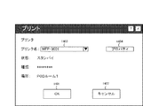
FIG. 23 is a diagram showing an example of a user interface displayed on the
24 is a diagram illustrating an example of a user interface displayed on the
なお、図24に示すUI画面は、図13において示したプリントメニュー1302に相当するメニューを図23において示した印刷アプリケーションによって選択した後にCRT310上に表示される。各種情報が記載されているが重要な部分に限定し以下説明を行う。
Note that the UI screen shown in FIG. 24 is displayed on the
図24において、ボタン2403が選択された場合、当該印刷ジョブは、印刷対象データを配送先毎に仕分けて出力する設定を当該印刷アプリケーションに与えていることを示している。このボタン2403が選択された状態でOKボタン2401を押下した場合、当該印刷アプリケーションに登録されている印刷対象データは、配送先毎にまとめられ、かつ配送先と配送先の出力物の境界で仕分け処理が実施され出力される。
In FIG. 24, when a
図25は、本実施形態を示す情報処理装置におけるデータ処理方法を説明するフローチャートである。本例は、コンピュータ上のCPU301によって実行される印刷アプリケーションプログラム604の印刷時の処理例である。なお、以降の説明において、本発明第3実施形態における印刷アプリケーションが第1実施形態において示した図面と共通の機能を有する場合には、第1実施形態における図面を一部引用し説明する。
FIG. 25 is a flowchart illustrating a data processing method in the information processing apparatus according to the present embodiment. This example is a processing example at the time of printing of the
印刷アプリケーションプログラム604による印刷処理は、図13において示したプリントメニュー1302が選択操作されたことを契機に開始される(S2501)。
Printing processing by the
次に、S2502に進み、CPU301は、印刷処理で使用するネットワーク100を経由し接続されているデジタル印刷機102との接続を確立する。具体的には、コンピュータ101が具備するNC312と、デジタル印刷機102が具備する外部I/F202との間のコネクションを確立しデータ送信の準備を行う。
In step S2502, the
S2503では、CPU301が仕分け対象となる配送先の情報のリストを取得する。ここで、配送先の情報とは、図23において示した印刷アプリケーションの画面における配送先フィールド2301内に記載された情報を含むユニークな要素の集合に対して順序を与えた情報である。ここで、順序としては、文字列をソートした順序としても構わない。また、配送先毎に順序を与えることが可能な印刷アプリケーションにおいては、当該指定された順序に基づきソートするような構成としても構わない。
In step S2503, the
S2504は、CPU301がS2503にて取得された配送先リストに含まれる全ての配送先に対して処理が完了したか否かの判別を行う。
In step S2504, the
ここで、配送先リストに含まれる全ての配送先に対して処理が完了しているとCPU301が判断した場合、全配送先について処理が終了した事を意味する為、S2513に進み、S2502で確立したコネクションを切断し、本処理を終了する。
Here, if the
一方、S2504で配送先リストに含まれる全ての配送先に対して処理が完了していないとCPU301が判断した場合、まだ処理が完了していない印刷対象データが残っていることを意味する。そこで、この場合には継続し処理を実行する為、S2505以降の処理に進む。
On the other hand, if the
S2505では、CPU301がS2503にて取得された配送先リストの中から未処理の配送先情報を選択する。
In S2505, the
次に、S2506では、CPU301は、仕分けコマンドをデジタル印刷機102に対して送信する。
In step S <b> 2506, the
なお、S2506において、仕分けコマンドを送信することの目的は以下の通りである。すなわち、S2507以降において、同一配送先に含まれる複数の印刷対象データの印刷処理が行われる。S2505において、選択された配送先に対応づけられた印刷対象データの処理が全て終了した段階で、再びS2504に戻り、S2503にて取得された配送先リストのさらなる次の配送先に対応づけられた印刷対象データの印刷を処理するループ処理を形成する。 Note that the purpose of transmitting the sorting command in S2506 is as follows. That is, in S2507 and subsequent steps, printing processing of a plurality of print target data included in the same delivery destination is performed. In step S2505, when all the processing of the print target data associated with the selected delivery destination is completed, the process returns to step S2504, and is associated with the next delivery destination in the delivery destination list acquired in step S2503. A loop process for processing printing of print target data is formed.
すなわち、ある配送先に対応づけられた印刷対象データの印刷処理の開始前に必ず仕分けコマンドをデジタル印刷機102に送信しておくことによって、結果的に図17において示したような、配送先毎に仕分けされた状態での出力処理を可能としている。
That is, by always sending a sorting command to the
S2507では、CPU301がS2505において選択された配送先に対応づけられた印刷対象データの全てについて、印刷処理が完了しているか否かの判別処理を行う。
In step S2507, the
ここで、選択された配送先に対応づけられた印刷対象データの全てについて、印刷処理が完了しているとCPU301が判断した場合、S2505において選択された配送先に対応づけられた印刷対象データは全て処理完了したことを意味する。そのため、次の配送先に対応づけられた印刷対象データの処理を実行する為再びS2504に戻る。
Here, when the
一方、選択された配送先に対応づけられた印刷対象データの全てについて、印刷処理が完了していないとCPU301が判断した場合S2508に進み、S2505において、選択された配送先に対応づけられた印刷対象データのうち次の印刷対象データを選択する。
On the other hand, if the
S2509では、CPU301がS2502の実行によって確立されたコンピュータ101およびデジタル印刷機102間のコネクションを通じてヘッダコマンドをコンピュータ101がデジタル印刷機102に対して送信する。ここで、コンピュータ101に送信される情報に関する説明は先の実施形態においてなされている為省略する。なお、S2509はコンピュータ101上のCPU301によって印刷アプリケーションプログラム604が実行されることにより処理される。
In step S <b> 2509, the
次に、S2510では、CPU301がS2508にて選択された印刷対象データを印刷ジョブデータに変換する処理を実施する。ここで、変換されるPDLデータの種別は任意である。すなわち、如何なるコマンドあるいはデータフォーマットが選択された場合においても本発明は有効である。
In step S2510, the
次に、S2511では、CPU301は、S2510にて作成および変換されたデータをコンピュータ101がデジタル印刷機102に送信する処理を実行する。送信処理が終了したら、S2512に進み、CPU301は、後処理コマンドを送信する。ここで、送信される情報に関する説明は左記の実施形態においてなされている為省略する。
In step S <b> 2511, the
このようにして、S2512が終了したら、CPU301は、再びS2507に戻り、次の印刷対象データの処理を実行するためのループを繰り返す。なお、S2512はコンピュータ101上のCPU301によって印刷アプリケーションプログラム604が実行されることにより処理される。
これによって、出力物をシフトして排紙する位置を、ユーザが手動で設定せずとも、配送先ごとに、出力物が、直前に排紙された出力物とはずれた状態で排紙されるため、ユーザは、配送先ごとの出力物を容易に区別でき、容易に取り分けることができる。
〔その他の実施形態〕
In this way, when S2512 ends, the
As a result, even if the user does not manually set the position to shift and output the output product, the output product is discharged in a state of being deviated from the output product output immediately before, for each delivery destination. Therefore, the user can easily distinguish the output products for each delivery destination, and can easily sort them.
[Other Embodiments]
上述した各実施形態においては、印刷仕様として、PDLデータを用いたシステムを例として説明した。印刷仕様の表現形態としては、ジョブは、所定のジョブチケット、例えばJDFなどのジョブチケットによる指定も可能である。この場合、印刷仕様は、印刷対象データから変換し作成された印刷ジョブデータとの分離および合成が容易であるという特徴を持つ。 In each of the above-described embodiments, a system using PDL data has been described as an example of print specifications. As an expression form of the printing specification, a job can be specified by a predetermined job ticket, for example, a job ticket such as JDF. In this case, the print specification has a feature that it can be easily separated and combined with print job data converted from print target data.
例えば、本発明による印刷アプリケーションプログラム604が仕分けコマンドを含む印刷仕様をJDF形式によって作成する能力を備えるならば、当該印刷ジョブデータはデジタル印刷機102のJDF機能プログラムによって実行可能である。
For example, if the
また、仕分け処理として、上述した実施形態の説明においては、排出装置が備えるシフト排紙機能を用いて実施する場合を例として示した。しかしながら、仕分け処理としては、シフト排紙機能以外にも各種存在する。
例えば、仕分け処理として、仕分け単位で出力シートの排出先を変更するという仕分け方法が考えられる。
さらに、仕分け処理として、仕分け単位で出力シートに挿入紙を挿入し、仕分け毎の出力物の境界部を明確にするなどの方法も考えられる。
Further, as an example of the sorting process, in the description of the above-described embodiment, the shift discharge function provided in the discharge device is used as an example. However, there are various sort processes other than the shift paper discharge function.
For example, as a sorting process, a sorting method in which the output sheet discharge destination is changed for each sorting unit is conceivable.
Further, as a sorting process, a method of inserting an insertion sheet into an output sheet in a sorting unit and clarifying a boundary portion of an output product for each sorting may be considered.
また、仕分け処理として、例えば図2に示すような大容量スタッカが、コントローラ部205からの指示によってその外蓋をオープンする機能を備えるならば、仕分けのタイミングで大容量スタッカ内の成果物を排出する処理によって仕分ける方法も考えられる。
上述した通り、仕分け処理の種別として如何なる方法を用いたとしても、本発明は適用される。
さらに、コントローラ部205が配送先別にシート束を排紙できる状態でないと判断した場合、シート束の排紙がエラーとなることを通知する通知処理を対応するステップを対応する実施形態に組み入れるように構成してもよい。
さらに、コントローラ部205がシート束の排紙中に、配送先別にシート束を排紙できる状態でないと判別した場合、シート束の排紙を中断するように制御してもよい。
Further, as a sorting process, for example, if a large-capacity stacker as shown in FIG. 2 has a function of opening the outer lid according to an instruction from the
As described above, the present invention is applied no matter what method is used as the type of sorting process.
Further, when the
Further, when the
本実施形態における図に示す機能が外部からインストールされるプログラムによって、ホストコンピュータにより遂行されていてもよい。尚、この場合に、各操作画面を含む本形態で述べた操作画面と同様の操作画面を表示させる為のデータを外部からインストールし、該ホストコンピュータの表示部に上記各種のユーザインタフェース画面を提供可能に構成する。このような構成の場合、CD−ROMやフラッシュメモリやFD等の記憶媒体により、あるいはネットワークを介して外部の記憶媒体から、プログラムを含む情報群を出力装置に供給される場合でも本発明は適用されるものである。 The functions shown in the drawings in this embodiment may be performed by the host computer by a program installed from the outside. In this case, data for displaying an operation screen similar to the operation screen described in this embodiment including each operation screen is installed from the outside, and the various user interface screens are provided on the display unit of the host computer. Configure as possible. In the case of such a configuration, the present invention is applied even when an information group including a program is supplied to an output device from a storage medium such as a CD-ROM, a flash memory, or an FD, or from an external storage medium via a network. It is what is done.
本発明は上記実施形態に限定されるものではなく、本発明の趣旨に基づき種々の変形(各実施形態の有機的な組合せを含む)が可能であり、それらを本発明の範囲から除外するものではない。例えば、上述した各種の設定画面を、デジタル印刷機102の操作部204に表示し、表示された設定画面を介して受け付けた設定に従って、コントローラ部205が、印刷及び仕分け処理を実行してもよい。つまり、コントローラ部205は、ユーザから指示されたタイミングで出力物がシフト排紙されるよう設定し、その設定に従って、ユーザから指示されたタイミングで出力物をシフト排紙すればよい。また、本実施形態では、デジタル印刷機102内部のコントローラ部205が上記各種制御の主体となっていたが、デジタル印刷機102と別筐体の外付けコントローラ等によって、上記各種制御の1部又は全部を実行可能に構成しても良い。
以上、本発明の様々な例と実施形態を示して説明したが、当業者であれば、本発明の趣旨と範囲は、本明細書内の特定の説明に限定されるのではない。
The present invention is not limited to the above embodiment, and various modifications (including organic combinations of the embodiments) are possible based on the spirit of the present invention, and these are excluded from the scope of the present invention. is not. For example, the various setting screens described above may be displayed on the
Although various examples and embodiments of the present invention have been shown and described above, the spirit and scope of the present invention are not limited to specific descriptions in the present specification by those skilled in the art.
本発明の各工程は、ネットワーク又は各種記憶媒体を介して取得したソフトウエア(プログラム)をパソコン(コンピュータ)等の処理装置(CPU、プロセッサ)にて実行することでも実現できる。 Each process of the present invention can also be realized by executing software (program) acquired via a network or various storage media by a processing device (CPU, processor) such as a personal computer (computer).
本発明は上記実施形態に限定されるものではなく、本発明の趣旨に基づき種々の変形(各実施形態の有機的な組合せを含む)が可能であり、それらを本発明の範囲から除外するものではない。 The present invention is not limited to the above embodiment, and various modifications (including organic combinations of the embodiments) are possible based on the spirit of the present invention, and these are excluded from the scope of the present invention. is not.
101 コンピュータ
200 シート処理装置
203 プリンタ部
204 操作部
205 コントローラ部
301 CPU
Claims (9)
前記受信手段により受信された印刷ジョブを実行することによりシートに画像を印刷する印刷手段と、
前記印刷ジョブに含まれる仕分けを行わせるための所定情報を検出する検出手段と、
前記検出手段が前記第1の印刷データと前記第2の印刷データの間で前記所定情報を検出していない場合、前記第2の印刷データに基づいて画像が印刷されたシートを前記第1の印刷データに基づいて画像が印刷されたシートと同じ位置に排出する第1の排出動作を実行し、前記検出手段が前記第1の印刷データと前記第2の印刷データの間で前記所定情報を検出した場合、前記第2の印刷データに基づいて画像が印刷されたシートを前記第1の印刷データに基づいて画像が印刷されたシートと異なる位置に排出する第2の排出動作を実行する排出手段と、
を備えることを特徴とする印刷装置。 Receiving means for receiving one print job in which the first print data and the second print data are linked;
Printing means for printing an image on a sheet by executing a print job received by the receiving means ;
Detection means for detecting predetermined information for performing sorting included in the print job ;
When the detection unit does not detect the predetermined information between the first print data and the second print data, a sheet on which an image is printed based on the second print data is stored in the first print data. Based on the print data, a first discharge operation is performed to discharge the image to the same position as the sheet on which the image has been printed, and the detection means outputs the predetermined information between the first print data and the second print data. when detecting, performing a second discharge operation for discharging the sheet on which the image is printed on the sheet with different positions on which an image is printed based on the first print data based on the second print data Discharging means;
A printing apparatus comprising:
前記受信手段により受信された印刷ジョブを実行することによりシートに画像を印刷する印刷手段と、
前記印刷ジョブに含まれる仕分けを行わせるための所定情報を検出する検出手段と、
前記検出手段が前記第1の印刷データと前記第2の印刷データに関連付けられた前記所定情報を検出していない場合、前記第2の印刷データに基づいて画像が印刷されたシートを前記第1の印刷データに基づいて画像が印刷されたシートと同じ位置に排出する第1の排出動作を実行し、前記検出手段が前記第1の印刷データと前記第2の印刷データに関連付けられた前記所定情報を検出した場合、前記第2の印刷データに基づいて画像が印刷されたシートを前記第1の印刷データに基づいて画像が印刷されたシートと異なる位置に排出する第2の排出動作を実行する排出手段と、
を備えることを特徴とする印刷装置。 Receiving means for receiving one print job in which the first print data and the second print data are linked;
Printing means for printing an image on a sheet by executing a print job received by the receiving means ;
Detection means for detecting predetermined information for performing sorting included in the print job ;
If the detection unit has not detected the predetermined information associated with the first print data and the second print data, a sheet on which an image is printed based on the second print data is displayed on the first print data. A first discharge operation is performed to discharge the image to the same position as the sheet on which the image is printed, and the detection unit associates the predetermined print data with the first print data and the second print data. when detecting information, the second discharge operation for discharging the sheet on which the image is printed based on the second print data on the sheet and different positions image is printed based on said first print data Discharging means to perform;
A printing apparatus comprising:
第1の印刷データと第2の印刷データとが連結された1つの印刷ジョブを受信する受信工程と、
前記受信工程で受信した印刷ジョブに含まれる仕分けを行わせるための所定情報を検出する検出工程と、
前記受信工程で受信された印刷ジョブを実行することによりシートに画像を印刷する印刷工程と、
前記検出工程で前記第1の印刷データと前記第2の印刷データの間で前記所定情報を検出していない場合、前記第2の印刷データに基づいて画像が印刷されたシートを前記第1の印刷データに基づいて画像が印刷されたシートと同じ位置に排出する第1の排出動作を実行し、前記検出工程で前記第1の印刷データと前記第2の印刷データの間で前記所定情報を検出した場合、前記第2の印刷データに基づいて画像が印刷されたシートを前記第1の印刷データに基づいて画像が印刷されたシートと異なる位置に排出する第2の排出動作を実行する排出工程と、
を備えることを特徴とする制御方法。 A control method of a printing apparatus capable of printing an image on a sheet based on a received print job,
A receiving step of receiving one print job in which the first print data and the second print data are linked;
A detection step for detecting predetermined information for performing sorting included in the print job received in the reception step ;
A printing step of printing an image on a sheet by executing the print job received in the reception step;
When the predetermined information is not detected between the first print data and the second print data in the detection step, a sheet on which an image is printed based on the second print data is used as the first print data. Based on the print data, a first discharge operation for discharging the image to the same position as the sheet on which the image is printed is executed, and the predetermined information is set between the first print data and the second print data in the detection step. If detected, a discharge for executing a second discharge operation for discharging the sheet on which the image is printed based on the second print data to a position different from the sheet on which the image is printed based on the first print data. Process,
A control method comprising:
第1の印刷データと第2の印刷データとが連結された1つの印刷ジョブを受信する受信工程と、
前記受信工程で受信した印刷ジョブに含まれる仕分けを行わせるための所定情報を検出する検出工程と、
前記受信工程で受信された印刷ジョブを実行することによりシートに画像を印刷する印刷工程と、
前記検出工程で前記第1の印刷データと前記第2の印刷データに関連付けられた前記所定情報を検出していない場合、前記第2の印刷データに基づいて画像が印刷されたシートを前記第1の印刷データに基づいて画像が印刷されたシートと同じ位置に排出する第1の排出動作を実行し、前記検出工程で前記第1の印刷データと前記第2の印刷データに関連付けられた前記所定情報を検出した場合、前記第2の印刷データに基づいて画像が印刷されたシートを前記第1の印刷データに基づいて画像が印刷されたシートと異なる位置に排出する第2の排出動作を実行する排出工程と、
を備えることを特徴とする制御方法。 A control method of a printing apparatus capable of printing an image on a sheet based on a received print job,
A receiving step of receiving one print job in which the first print data and the second print data are linked;
A detection step for detecting predetermined information for performing sorting included in the print job received in the reception step ;
A printing step of printing an image on a sheet by executing the print job received in the reception step;
If the predetermined information associated with the first print data and the second print data is not detected in the detection step, a sheet on which an image is printed based on the second print data is used as the first print data. A first discharge operation is performed to discharge the image to the same position as the sheet on which the image is printed based on the print data, and the predetermined step associated with the first print data and the second print data in the detection step when detecting information, the second discharge operation for discharging the sheet on which the image is printed based on the second print data on the sheet and different positions image is printed based on said first print data A discharge process to be performed;
A control method comprising:
Priority Applications (6)
| Application Number | Priority Date | Filing Date | Title |
|---|---|---|---|
| JP2012139822A JP6087522B2 (en) | 2012-06-21 | 2012-06-21 | Printing apparatus, printing apparatus control method, and program |
| US13/915,550 US9073726B2 (en) | 2012-06-21 | 2013-06-11 | Printing apparatus and control method of printing apparatus |
| EP13172653.1A EP2676911B1 (en) | 2012-06-21 | 2013-06-19 | Printing apparatus and control method of printing apparatus |
| KR1020130070760A KR101624881B1 (en) | 2012-06-21 | 2013-06-20 | Printing apparatus and control method of printing apparatus |
| CN201310247386.1A CN103507445B (en) | 2012-06-21 | 2013-06-20 | Printing apparatus and control method of printing apparatus |
| US14/716,446 US9658812B2 (en) | 2012-06-21 | 2015-05-19 | Printing apparatus and control method of printing apparatus |
Applications Claiming Priority (1)
| Application Number | Priority Date | Filing Date | Title |
|---|---|---|---|
| JP2012139822A JP6087522B2 (en) | 2012-06-21 | 2012-06-21 | Printing apparatus, printing apparatus control method, and program |
Publications (3)
| Publication Number | Publication Date |
|---|---|
| JP2014004688A JP2014004688A (en) | 2014-01-16 |
| JP2014004688A5 JP2014004688A5 (en) | 2015-08-06 |
| JP6087522B2 true JP6087522B2 (en) | 2017-03-01 |
Family
ID=48792954
Family Applications (1)
| Application Number | Title | Priority Date | Filing Date |
|---|---|---|---|
| JP2012139822A Active JP6087522B2 (en) | 2012-06-21 | 2012-06-21 | Printing apparatus, printing apparatus control method, and program |
Country Status (5)
| Country | Link |
|---|---|
| US (2) | US9073726B2 (en) |
| EP (1) | EP2676911B1 (en) |
| JP (1) | JP6087522B2 (en) |
| KR (1) | KR101624881B1 (en) |
| CN (1) | CN103507445B (en) |
Families Citing this family (11)
| Publication number | Priority date | Publication date | Assignee | Title |
|---|---|---|---|---|
| JP6087522B2 (en) * | 2012-06-21 | 2017-03-01 | キヤノン株式会社 | Printing apparatus, printing apparatus control method, and program |
| JP2014046681A (en) * | 2012-09-04 | 2014-03-17 | Canon Inc | Printing device, control method thereof, and program |
| JP6261195B2 (en) | 2012-12-14 | 2018-01-17 | キヤノン株式会社 | Printing apparatus and control method and program therefor |
| JP6281122B2 (en) * | 2013-12-27 | 2018-02-21 | パナソニックIpマネジメント株式会社 | Information processing device |
| JP2016117203A (en) | 2014-12-19 | 2016-06-30 | キヤノン株式会社 | Printer, control method and program thereof |
| EP3271174B1 (en) * | 2015-06-29 | 2020-03-11 | Koenig & Bauer AG | Delivery device having two discharging stations and method for adjusting |
| JP6668837B2 (en) * | 2016-03-10 | 2020-03-18 | 富士ゼロックス株式会社 | Print control program, information processing apparatus and print system |
| JP6813959B2 (en) * | 2016-04-05 | 2021-01-13 | キヤノン株式会社 | System and its control method, image forming apparatus and its control method, and program |
| JP6949578B2 (en) * | 2017-06-23 | 2021-10-13 | キヤノン株式会社 | Image forming device, control method and program of image forming device |
| JP7043859B2 (en) * | 2018-02-01 | 2022-03-30 | セイコーエプソン株式会社 | Printing device and control method of printing device |
| JP7286942B2 (en) * | 2018-10-24 | 2023-06-06 | コニカミノルタ株式会社 | Image forming system and program |
Family Cites Families (23)
| Publication number | Priority date | Publication date | Assignee | Title |
|---|---|---|---|---|
| US5316279A (en) * | 1993-01-04 | 1994-05-31 | Xerox Corporation | Copier/printer job stacking with discrete cover sheets with extending printed banners |
| US5848346A (en) * | 1994-08-08 | 1998-12-08 | Canon Kabushiki Kaisha | Image forming apparatus for offsetting output sheet |
| US5898592A (en) * | 1996-09-26 | 1999-04-27 | Xerox Corporation | Sheet delivery control system |
| JP3743477B2 (en) * | 1998-09-09 | 2006-02-08 | コニカミノルタビジネステクノロジーズ株式会社 | Image forming apparatus |
| JP2001180084A (en) * | 1999-12-24 | 2001-07-03 | Canon Inc | Output unit and output controller, information processing system, and output control method |
| JP2001205899A (en) * | 2000-01-26 | 2001-07-31 | Canon Inc | Image output unit, image processing system, sheet discharge control method, and storage medium |
| JP2005149154A (en) * | 2003-11-14 | 2005-06-09 | Konica Minolta Business Technologies Inc | Printing controller, printing apparatus, printing control method, printing control program, and computer-readable recording medium having printing control program recorded thereon |
| JP4112525B2 (en) * | 2004-05-28 | 2008-07-02 | 京セラミタ株式会社 | Image forming apparatus |
| JP2006092405A (en) * | 2004-09-27 | 2006-04-06 | Matsushita Electric Ind Co Ltd | Printer and printed matter discharge method |
| JP2006268110A (en) * | 2005-03-22 | 2006-10-05 | Fuji Xerox Co Ltd | Printing job processing program and its method and distribution/delivery system |
| JP4748306B2 (en) | 2005-08-10 | 2011-08-17 | セイコーエプソン株式会社 | Recording apparatus and liquid ejecting apparatus |
| JP2007218962A (en) * | 2006-02-14 | 2007-08-30 | Matsushita Electric Ind Co Ltd | Image forming apparatus |
| JP5043422B2 (en) | 2006-12-20 | 2012-10-10 | キヤノン株式会社 | Printing system, job processing method, program, and storage medium |
| JP2009096145A (en) * | 2007-10-19 | 2009-05-07 | Konica Minolta Business Technologies Inc | Image forming apparatus |
| JP4513884B2 (en) | 2008-03-27 | 2010-07-28 | コニカミノルタビジネステクノロジーズ株式会社 | Sheet stacking apparatus and image forming system |
| JP4664391B2 (en) | 2008-04-28 | 2011-04-06 | シャープ株式会社 | Print output device and print output system |
| JP5006256B2 (en) | 2008-05-23 | 2012-08-22 | オリンパス株式会社 | Stack apparatus and image forming apparatus having the stack apparatus |
| JP2009285848A (en) * | 2008-05-27 | 2009-12-10 | Kyocera Mita Corp | Image forming apparatus |
| JP2011006169A (en) * | 2009-06-24 | 2011-01-13 | Murata Machinery Ltd | Image forming apparatus |
| JP5627347B2 (en) | 2009-09-10 | 2014-11-19 | キヤノン株式会社 | Image forming apparatus and double-sided printing method |
| JP5483966B2 (en) | 2009-09-17 | 2014-05-07 | キヤノン株式会社 | Printing apparatus, printing control apparatus and control method therefor |
| KR20110100410A (en) | 2010-03-04 | 2011-09-14 | 삼성전자주식회사 | Print medium finishing apparatus and control method thereof |
| JP6087522B2 (en) * | 2012-06-21 | 2017-03-01 | キヤノン株式会社 | Printing apparatus, printing apparatus control method, and program |
-
2012
- 2012-06-21 JP JP2012139822A patent/JP6087522B2/en active Active
-
2013
- 2013-06-11 US US13/915,550 patent/US9073726B2/en not_active Expired - Fee Related
- 2013-06-19 EP EP13172653.1A patent/EP2676911B1/en active Active
- 2013-06-20 KR KR1020130070760A patent/KR101624881B1/en active IP Right Grant
- 2013-06-20 CN CN201310247386.1A patent/CN103507445B/en active Active
-
2015
- 2015-05-19 US US14/716,446 patent/US9658812B2/en active Active
Also Published As
| Publication number | Publication date |
|---|---|
| EP2676911B1 (en) | 2018-11-28 |
| US9658812B2 (en) | 2017-05-23 |
| CN103507445B (en) | 2017-04-26 |
| KR101624881B1 (en) | 2016-05-27 |
| CN103507445A (en) | 2014-01-15 |
| US20150254040A1 (en) | 2015-09-10 |
| US20130341861A1 (en) | 2013-12-26 |
| KR20130143502A (en) | 2013-12-31 |
| US9073726B2 (en) | 2015-07-07 |
| EP2676911A1 (en) | 2013-12-25 |
| JP2014004688A (en) | 2014-01-16 |
Similar Documents
| Publication | Publication Date | Title |
|---|---|---|
| JP6087522B2 (en) | Printing apparatus, printing apparatus control method, and program | |
| US8099038B2 (en) | Image forming apparatus, method for controlling image forming apparatus, and storage medium | |
| KR101238615B1 (en) | Printing control apparatus and information processing apparatus and method for controlling a printing apparatus and method for controlling an information processing apparatus and computer-readable storage medium | |
| KR100871036B1 (en) | Print system, job processing method, and storage medium | |
| US8564810B2 (en) | Job management apparatus, job management method, and storage medium for using information of a post-processing apparatus to manage a print job | |
| US9057995B2 (en) | Printing system, job processing method, storage medium, and printing apparatus | |
| JP5294656B2 (en) | Printing system, control method thereof, and program | |
| US7855792B2 (en) | Printing system, job processing method, printing device, and storage medium | |
| US8243299B2 (en) | Printing apparatus with recovery from interruption factor, controlling method, and storage medium | |
| CN102455882B (en) | image forming apparatus and print job control method | |
| JP5305930B2 (en) | Image forming apparatus, job processing method, program, and storage medium | |
| US20110063657A1 (en) | Print apparatus and method of controlling the apparatus and program thereof | |
| JP2008165708A (en) | Printing system, control method of printing system, printer, storage medium, and program | |
| JP6147106B2 (en) | Printing apparatus, control method therefor, program, and storage medium | |
| US9211694B2 (en) | Image forming apparatus, print control method and storage medium storing program | |
| JP4235437B2 (en) | Control apparatus and control method | |
| JP2013208824A (en) | Variable printing system | |
| JP2016084184A (en) | Control method for image formation system comprising image formation apparatus and post-processing device connected to the same, and program |
Legal Events
| Date | Code | Title | Description |
|---|---|---|---|
| A521 | Written amendment |
Free format text: JAPANESE INTERMEDIATE CODE: A523 Effective date: 20150619 |
|
| A621 | Written request for application examination |
Free format text: JAPANESE INTERMEDIATE CODE: A621 Effective date: 20150619 |
|
| RD03 | Notification of appointment of power of attorney |
Free format text: JAPANESE INTERMEDIATE CODE: A7423 Effective date: 20150724 |
|
| A131 | Notification of reasons for refusal |
Free format text: JAPANESE INTERMEDIATE CODE: A131 Effective date: 20160607 |
|
| A521 | Written amendment |
Free format text: JAPANESE INTERMEDIATE CODE: A523 Effective date: 20160805 |
|
| TRDD | Decision of grant or rejection written | ||
| A01 | Written decision to grant a patent or to grant a registration (utility model) |
Free format text: JAPANESE INTERMEDIATE CODE: A01 Effective date: 20170105 |
|
| A61 | First payment of annual fees (during grant procedure) |
Free format text: JAPANESE INTERMEDIATE CODE: A61 Effective date: 20170202 |
|
| R151 | Written notification of patent or utility model registration |
Ref document number: 6087522 Country of ref document: JP Free format text: JAPANESE INTERMEDIATE CODE: R151 |