JP6086007B2 - Storage control device control program, storage control device control method, storage control device, and storage system - Google Patents
Storage control device control program, storage control device control method, storage control device, and storage system Download PDFInfo
- Publication number
- JP6086007B2 JP6086007B2 JP2013065204A JP2013065204A JP6086007B2 JP 6086007 B2 JP6086007 B2 JP 6086007B2 JP 2013065204 A JP2013065204 A JP 2013065204A JP 2013065204 A JP2013065204 A JP 2013065204A JP 6086007 B2 JP6086007 B2 JP 6086007B2
- Authority
- JP
- Japan
- Prior art keywords
- area
- unit
- storage
- storage device
- moving
- Prior art date
- Legal status (The legal status is an assumption and is not a legal conclusion. Google has not performed a legal analysis and makes no representation as to the accuracy of the status listed.)
- Active
Links
Images


Classifications
-
- G—PHYSICS
- G06—COMPUTING; CALCULATING OR COUNTING
- G06F—ELECTRIC DIGITAL DATA PROCESSING
- G06F3/00—Input arrangements for transferring data to be processed into a form capable of being handled by the computer; Output arrangements for transferring data from processing unit to output unit, e.g. interface arrangements
- G06F3/06—Digital input from, or digital output to, record carriers, e.g. RAID, emulated record carriers or networked record carriers
- G06F3/0601—Interfaces specially adapted for storage systems
- G06F3/0602—Interfaces specially adapted for storage systems specifically adapted to achieve a particular effect
- G06F3/061—Improving I/O performance
- G06F3/0611—Improving I/O performance in relation to response time
-
- G—PHYSICS
- G06—COMPUTING; CALCULATING OR COUNTING
- G06F—ELECTRIC DIGITAL DATA PROCESSING
- G06F3/00—Input arrangements for transferring data to be processed into a form capable of being handled by the computer; Output arrangements for transferring data from processing unit to output unit, e.g. interface arrangements
- G06F3/06—Digital input from, or digital output to, record carriers, e.g. RAID, emulated record carriers or networked record carriers
- G06F3/0601—Interfaces specially adapted for storage systems
- G06F3/0628—Interfaces specially adapted for storage systems making use of a particular technique
- G06F3/0638—Organizing or formatting or addressing of data
- G06F3/0644—Management of space entities, e.g. partitions, extents, pools
-
- G—PHYSICS
- G06—COMPUTING; CALCULATING OR COUNTING
- G06F—ELECTRIC DIGITAL DATA PROCESSING
- G06F3/00—Input arrangements for transferring data to be processed into a form capable of being handled by the computer; Output arrangements for transferring data from processing unit to output unit, e.g. interface arrangements
- G06F3/06—Digital input from, or digital output to, record carriers, e.g. RAID, emulated record carriers or networked record carriers
- G06F3/0601—Interfaces specially adapted for storage systems
- G06F3/0628—Interfaces specially adapted for storage systems making use of a particular technique
- G06F3/0646—Horizontal data movement in storage systems, i.e. moving data in between storage devices or systems
- G06F3/0647—Migration mechanisms
-
- G—PHYSICS
- G06—COMPUTING; CALCULATING OR COUNTING
- G06F—ELECTRIC DIGITAL DATA PROCESSING
- G06F3/00—Input arrangements for transferring data to be processed into a form capable of being handled by the computer; Output arrangements for transferring data from processing unit to output unit, e.g. interface arrangements
- G06F3/06—Digital input from, or digital output to, record carriers, e.g. RAID, emulated record carriers or networked record carriers
- G06F3/0601—Interfaces specially adapted for storage systems
- G06F3/0668—Interfaces specially adapted for storage systems adopting a particular infrastructure
- G06F3/0671—In-line storage system
- G06F3/0683—Plurality of storage devices
- G06F3/0685—Hybrid storage combining heterogeneous device types, e.g. hierarchical storage, hybrid arrays
Landscapes
- Engineering & Computer Science (AREA)
- Theoretical Computer Science (AREA)
- Human Computer Interaction (AREA)
- Physics & Mathematics (AREA)
- General Engineering & Computer Science (AREA)
- General Physics & Mathematics (AREA)
- Debugging And Monitoring (AREA)
- Information Retrieval, Db Structures And Fs Structures Therefor (AREA)
Description
本発明は、ストレージ制御装置の制御プログラム、ストレージ制御装置の制御方法、ストレージ制御装置及びストレージシステムに関する。 The present invention relates to a storage control device control program, a storage control device control method, a storage control device, and a storage system.
HDD(Hard Disk Drive)などのストレージ装置のワークロード分析を行うと、一部の領域に負荷が偏ることが多く見られる。図14は、ワークロードの分析例を示す図であり、縦軸は下に向かってオフセットを示し、横軸は経過時間を示す。ここで、オフセットは、利用者に割り当てられたボリュームの先頭アドレスからの差を表す。また、経過時間の単位は分である。 When a workload analysis of a storage device such as an HDD (Hard Disk Drive) is performed, the load is often biased to some areas. FIG. 14 is a diagram illustrating an analysis example of a workload, where the vertical axis indicates an offset downward and the horizontal axis indicates an elapsed time. Here, the offset represents a difference from the head address of the volume assigned to the user. The unit of elapsed time is minutes.
図14では黒い部分が負荷が高い領域であり、図14には高負荷領域として3つの塊がある。高負荷領域のうち毎日同様に発生する領域については、静的階層制御が有効である。ここで、静的階層制御とは、毎日決まった時間にそれまでの統計情報を用いて負荷の高い領域のデータをSSD(Solid State Drive)などHDDと比較して高速なストレージ装置に移動する技術である。 In FIG. 14, the black portion is a high load area, and in FIG. 14, there are three blocks as the high load area. Static tier control is effective for regions that occur in the same way in a high load region. Here, static tier control is a technology that uses statistical information so far to move data in a high-load area to a high-speed storage device compared to an HDD such as an SSD (Solid State Drive) at a fixed time every day. It is.
例えば、図14において、3つの塊のうち塊A及び塊Bが毎日同様に発生する場合には、塊A及び塊Bに対応するデータをSSDに移動することによって、頻繁にアクセスされるデータが高速にアクセスされることになる。したがって、静的階層制御を用いることにより、情報処理システムの性能を向上させることができる。 For example, in FIG. 14, when the chunk A and the chunk B of the three chunks are generated every day in the same manner, the data frequently accessed can be obtained by moving the data corresponding to the chunk A and the chunk B to the SSD. It will be accessed at high speed. Therefore, the performance of the information processing system can be improved by using the static hierarchy control.
一方、図14において、塊Cが当日だけに発生する場合には、静的階層制御で塊CをSSDに移動しておくことはできない。このため、塊Cに対しては、リアルタイムに測定した負荷に基づいて高負荷領域のデータをSSDに移動する動的階層制御が行われる(例えば、非特許文献1参照。)。 On the other hand, in FIG. 14, when the chunk C occurs only on the current day, the chunk C cannot be moved to the SSD by the static hierarchical control. For this reason, dynamic tier control is performed on the block C to move data in a high load area to the SSD based on the load measured in real time (see, for example, Non-Patent Document 1).
また、高アクセス頻度ファイルへのアクセスが発生した時点で、ディスクアレイ装置が、ファイルの使用するセクター等の関連情報を元に、ハードディスク内の所定近傍に位置するセクターに格納されているデータをキャッシュに読み込む従来技術がある。また、アクセスされた論理トラックが存在する割合である存在密度が増加又は一定値以上であれば順アクセス又は大局的な順アクセスと判断し、データが存在するブロック近傍を外部記憶装置から先読みする従来技術がある。また、キュッシュを有するディスク制御装置で、アクセスする物理的な領域の周辺部も併せてロードする従来技術がある。 In addition, when an access to a high access frequency file occurs, the disk array device caches data stored in a sector located in a predetermined vicinity in the hard disk based on related information such as the sector used by the file. There is a conventional technology to read in. Further, if the presence density, which is the ratio of the accessed logical tracks, increases or exceeds a certain value, it is determined as sequential access or global sequential access, and the block neighborhood where data exists is pre-read from the external storage device There is technology. In addition, there is a conventional technique in which a peripheral part of a physical area to be accessed is loaded together with a disk controller having a cache.
リアルタイムに測定した負荷に基づいて高負荷領域のデータをSSDに移動する動的階層制御に、高負荷領域の近傍のデータも移動する従来技術を適用することにより、情報処理システムの性能を向上させることができる。しかしながら、高負荷領域の近傍のデータをSSDに移動するためには、近傍として適切な領域を選択する必要がある。 Improve the performance of the information processing system by applying the conventional technology that moves data in the vicinity of the high load area to the dynamic hierarchy control that moves the data in the high load area to the SSD based on the load measured in real time. be able to. However, in order to move data in the vicinity of the high load area to the SSD, it is necessary to select an appropriate area as the vicinity.
本発明は、1つの側面では、高負荷領域の近傍を適切に選択するストレージ制御装置の制御プログラム、ストレージ制御装置の制御方法、ストレージ制御装置及びストレージシステムを提供することを目的とする。 An object of one aspect of the present invention is to provide a storage control device control program, a storage control device control method, a storage control device, and a storage system that appropriately select the vicinity of a high load area.
本願の開示するストレージ制御装置の制御プログラムは、1つの態様において、ストレージ制御装置に、第1の記憶装置で使用される領域を所定の大きさで分割した複数の単位領域について単位領域ごとに入出力数を集計させる。そして、制御プログラムは、ストレージ制御装置に、前記入出力数が第1の閾値より大きな単位領域を高負荷領域として特定させる。そして、制御プログラムは、ストレージ制御装置に、特定させた高負荷領域と所定の距離内にある単位領域をオフセットの上下両方向に繋ぎ合わせた拡張領域と該拡張領域とつながる他の拡張領域とを合わせた領域を移動領域として特定させる。そして、制御プログラムは、ストレージ制御装置に、特定させた移動領域のデータを第1の記憶装置より高速な第2の記憶装置に移動させる。 In one aspect, a control program for a storage control device disclosed in the present application stores, for each unit area, a plurality of unit areas obtained by dividing an area used by a first storage device into a predetermined size. Aggregate the number of outputs. Then, the control program causes the storage control device to identify a unit area in which the number of inputs / outputs is greater than the first threshold as a high load area. Then, the control program matches the storage area with the extended area obtained by connecting the specified high load area and the unit area within a predetermined distance in both the upper and lower directions of the offset and the other extended area connected to the extended area. The specified area is specified as the movement area. Then, the control program causes the storage control device to move the data in the specified movement area to the second storage device that is faster than the first storage device.
1実施態様によれば、高負荷領域の近傍を適切に選択することができる。 According to one embodiment, the vicinity of the high load region can be appropriately selected.
以下に、本願の開示するストレージ制御装置の制御プログラム、ストレージ制御装置の制御方法、ストレージ制御装置及びストレージシステムの実施例を図面に基づいて詳細に説明する。なお、この実施例は開示の技術を限定するものではない。 Embodiments of a storage control device control program, a storage control device control method, a storage control device, and a storage system disclosed in the present application will be described below in detail with reference to the drawings. Note that this embodiment does not limit the disclosed technology.
まず、実施例に係る階層ストレージ制御装置による動的階層制御について説明する。図1A及び図1Bは、実施例に係る階層ストレージ制御装置による動的階層制御を説明するための図である。 First, dynamic tier control by the tier storage control apparatus according to the embodiment will be described. 1A and 1B are diagrams for explaining dynamic tier control by the tier storage control apparatus according to the embodiment.
図1Aは、ストレージ装置のワークロードの分析例を示す図であり、縦軸は下に向かってオフセットを示し、横軸は経過時間を示す。図1Aにおいて、網掛けの領域1が高負荷領域を示す。実施例に係る階層ストレージ制御装置は、図の矢印2が示すように、高負荷領域からある決めた範囲を拡張領域とする。
FIG. 1A is a diagram illustrating an analysis example of a workload of a storage apparatus, where the vertical axis indicates an offset downward and the horizontal axis indicates an elapsed time. In FIG. 1A, a
そして、実施例に係る階層ストレージ制御装置は、拡張領域と、拡張領域とつながる別の拡張領域とを合わせて1つの拡張領域とみなす。そして、実施例に係る階層ストレージ制御装置は、拡張領域をSSDにデータを移動する移動領域とする。図1Aでは、上下の破線の間の領域が移動領域である。 Then, the hierarchical storage control apparatus according to the embodiment regards the extension area and another extension area connected to the extension area as one extension area. Then, the hierarchical storage control apparatus according to the embodiment sets the expansion area as a movement area for moving data to the SSD. In FIG. 1A, the area between the upper and lower broken lines is the moving area.
また、実施例に係る階層ストレージ制御装置は、ある時点で移動領域を決定すると、一定時間高負荷が発生しなくなるまで、移動領域を維持する。すなわち、実施例に係る階層ストレージ制御装置は、高負荷領域が消滅し、一定時間高負荷が発生しないと高負荷は消滅したとみなす。図1Aでは、タイムアウトの矢印が高負荷が発生しない一定時間を示す。 In addition, when the hierarchical storage control apparatus according to the embodiment determines the moving area at a certain time, the moving area is maintained until a high load does not occur for a certain time. That is, the hierarchical storage control apparatus according to the embodiment considers that the high load has disappeared if the high load area disappears and no high load occurs for a certain period of time. In FIG. 1A, a time-out arrow indicates a certain time during which no high load occurs.
図1Bは、ストレージ装置のワークロードの他の分析例を示す図であり、縦軸は上に向かってオフセットを示し、横軸は経過時間を示す。また、ボリュームは1GB(ギガバイト)単位のセグメントに分割され、経過時間は1分間を単位としている。すなわち、図1Bにおいて、網掛けの正方形領域3は、1つのセグメントが1分間高負荷であったことを示す。また、sは高負荷領域から拡張領域として拡張するセグメント数を示し、図1Bではs=1である。
FIG. 1B is a diagram illustrating another analysis example of the workload of the storage apparatus, where the vertical axis indicates an offset upward and the horizontal axis indicates an elapsed time. The volume is divided into 1 GB (gigabyte) segments, and the elapsed time is set to 1 minute. That is, in FIG. 1B, the shaded
そして、実施例に係る階層ストレージ制御装置は、高負荷領域のセグメント間で距離がs以内のものを繋ぎ合わせてn_セグメントを作成する。n_セグメントは、SSDにデータが移動される移動領域であり、データの移動について一体制御される。n_セグメントのセグメント数は2s+1以上となる。図1Bでは、セグメント数が5の2つのn_セグメントが特定されている。 Then, the hierarchical storage control apparatus according to the embodiment creates n_segments by connecting the segments having a distance of s or less between the segments in the high load area. The n_segment is a movement area where data is moved to the SSD, and the data movement is integrally controlled. The number of segments of the n_segment is 2s + 1 or more. In FIG. 1B, two n_segments with five segments are identified.
このように、実施例に係る階層ストレージ制御装置は、SSDにデータを移動する領域としてn_セグメントを特定することにより、高負荷領域の近傍として適切な領域を選択することができる。 As described above, the hierarchical storage control apparatus according to the embodiment can select an appropriate area as the vicinity of the high load area by specifying the n_segment as the area for moving data to the SSD.
次に、実施例に係る階層ストレージ制御装置の機能構成について説明する。図2は、実施例に係る階層ストレージ制御装置の機能構成を示す図である。図2に示すように、階層ストレージ制御装置100は、階層管理部110と、階層ドライバ120と、SSDドライバ130と、HDDドライバ140とを有する。
Next, the functional configuration of the hierarchical storage control apparatus according to the embodiment will be described. FIG. 2 is a diagram illustrating a functional configuration of the hierarchical storage control apparatus according to the embodiment. As illustrated in FIG. 2, the hierarchical
なお、階層ストレージ制御装置100は、SSD200及びHDD300とともに階層ストレージシステムを形成する。また、階層ストレージ制御装置100は、階層ストレージ制御装置100と同様の機能構成を有する階層ストレージ制御プログラムがコンピュータで実行されることにより実現される。また、階層管理部110は、ユーザ空間で実行されるプログラムとして実現され、階層ドライバ120、SSDドライバ130、HDDドライバ140はOS空間で実行されるプログラムとして実現される。
The hierarchical
階層管理部110は、blktrace又はiostatを用いてHDD300についてトレースされたIOの情報に基づいて、SSD200にデータを移動するn_セグメントを決定し、決定したn_セグメントのデータの移動を階層ドライバ120に指示する。ここで、blktraceはブロックI/OレイヤレベルでのIOをトレースするコマンドであり、iostatはディスクI/Oの利用状況を確認するコマンドである。blktrace及びiostatはOS空間で実行される。
The
階層管理部110は、データ収集部111と、データベース112と、ワークロード分析部113と、移動指示部116とを有する。
The
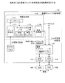
データ収集部111は、blktrace又はiostatを用いてHDD300についてトレースされたIOの情報を1分間隔で収集し、収集した情報に基づいてn_セグメントを特定する。そして、データ収集部111は、特定したn_セグメントについてn_セグメント番号を採番し、n_セグメント番号、セグメント範囲、IO数をタイムスタンプとともにデータベース112に書き込む。
The
ここで、n_セグメント番号は、n_セグメントを識別する番号であり、セグメント範囲は、n_セグメントの先頭セグメント及び最終セグメントのオフセットである。IO数は、n_セグメントに対して1分間に行われたIOの合計数であり、タイムスタンプは、時刻を識別する識別子である。ただし、データ収集部111は、過去に採番したn_セグメントとセグメント範囲が同じn_セグメントについては、新たに採番することなく、過去に採番したn_セグメント番号を用いる。
Here, the n_segment number is a number for identifying the n_segment, and the segment range is the offset of the first segment and the last segment of the n_segment. The number of IOs is the total number of IOs performed per minute for the n_segment, and the time stamp is an identifier for identifying time. However, the
データ収集部111は、図1Bに示したように、高負荷領域のセグメント間で距離がs以内のものを繋ぎ合わせてn_セグメントを作成する。データ収集部111が、高負荷領域のセグメント間で距離がs以内のものを繋ぎ合わせてn_セグメントを作成することによって、階層ストレージ制御装置100は、高負荷領域の近傍として適切な領域を選択することができる。
As illustrated in FIG. 1B, the
データベース112は、データ収集部111により特定されたn_セグメントに関する情報を記憶する。図3は、データベース112の一例を示す図である。図3に示すように、データベース112は、n_セグメント毎に、n_セグメント番号、セグメント範囲、IO数及びタイムスタンプを対応させて記憶する。例えば、n_セグメント番号が「1」であるn_セグメントは、先頭セグメントのオフセットが「3」であり、最終セグメントのオフセットが「5」であり、IO数が「1000」であり、タイムスタンプが「1」である。
The
ワークロード分析部113は、データベース112が記憶するn_セグメントから、SSD200にデータを移動するn_セグメントを選択し、選択したn_セグメントに関する情報を移動指示部116に渡す。
The workload analysis unit 113 selects an n_segment whose data is to be moved to the
具体的には、ワークロード分析部113は、IO数が多い順にn_セグメントを並べ替える。そして、ワークロード分析部113は、以下の計算をmがmax_seg_numに達するか、io_rateがio_rate_valueを超えるまで行う。

io_rate_valueは、SSD200へデータを移動する候補としてトップk個のn_セグメントを選択するか否かの閾値である。すなわち、ワークロード分析部113は、io_rateがio_rate_valueを超えた場合は、トップk個のn_セグメントへのアクセスの集中率が高いので、トップk個のn_セグメントをSSD200へデータを移動する候補とする。
io_rate_value is a threshold value indicating whether or not to select the top k n_segments as candidates for moving data to the
また、ワークロード分析部113は、候補テーブル114及び管理テーブル115を有し、SSD200へデータを移動する候補を候補テーブル114に登録し、SSD200へデータを移動する対象として選択したn_セグメントを管理テーブル115に登録する。
The workload analysis unit 113 also has a candidate table 114 and a management table 115, registers candidates for moving data to the
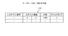
図4は、候補テーブル114の一例を示す図である。図4に示すように、候補テーブル114は、n_セグメント毎に、n_セグメント番号と、先頭セグメント番号と、セグメント数と、連続数とを対応させて記憶する。ここで、先頭セグメント番号は、n_セグメントの先頭セグメントのオフセットである。セグメント数は、n_セグメントに含まれるセグメントの個数である。 FIG. 4 is a diagram illustrating an example of the candidate table 114. As illustrated in FIG. 4, the candidate table 114 stores an n_segment number, a head segment number, a segment number, and a continuous number in association with each n_segment. Here, the head segment number is an offset of the head segment of the n_segment. The number of segments is the number of segments included in the n_segment.
また、連続数は、候補として連続して候補テーブル114に登録された回数を示す。ワークロード分析部113は、1分間隔で特定のタイムスタンプの全てのn_セグメントを取り出し、io_concentration及びio_rateを計算する。そして、ワークロード分析部113は、io_rateがio_rate_valueを超える候補を特定して候補テーブル114に登録する場合に、以前に登録されているn_セグメントについては連続数に「1」を加える。また、ワークロード分析部113は、候補を候補テーブル114に登録する場合に、候補が未登録である場合には、新たにエントリを作成して連続数を「0」にする。また、ワークロード分析部113は、候補テーブル114に登録されていて、今回は候補として特定されなかったn_セグメントについては連続数を「0」にリセットする。なお、連続数の初期値は「0」である。 Further, the continuous number indicates the number of times registered as candidates in the candidate table 114 continuously. The workload analysis unit 113 extracts all n_segments of a specific time stamp at 1 minute intervals, and calculates io_concentration and io_rate. Then, the workload analysis unit 113 adds “1” to the number of consecutive n_segments that have been registered before when a candidate whose io_rate exceeds io_rate_value is specified and registered in the candidate table 114. In addition, when the candidate is registered in the candidate table 114 when the candidate is not registered, the workload analysis unit 113 creates a new entry and sets the continuous number to “0”. In addition, the workload analysis unit 113 resets the continuous number to “0” for n_segments registered in the candidate table 114 and not identified as candidates this time. Note that the initial value of the continuous number is “0”.
そして、ワークロード分析部113は、連続数が所定の閾値を超え、かつ、IOの集中率が高い状態がデータをSSD200に移動するために必要な時間より長く続くことが期待されるn_セグメントを、SSD200にデータを移動する対象として選択する。そして、ワークロード分析部113は、移動対象として選択したn_セグメントを管理テーブル115に登録する。
Then, the workload analysis unit 113 selects n_segments in which the number of consecutive times exceeds a predetermined threshold and the state where the IO concentration rate is high is expected to last longer than the time required to move data to the
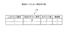
図5は、管理テーブル115の一例を示す図である。図5に示すように、管理テーブル115は、n_セグメント毎に、n_セグメント番号と、先頭セグメント番号と、セグメント数と、連続数とを対応させて記憶する。 FIG. 5 is a diagram illustrating an example of the management table 115. As illustrated in FIG. 5, the management table 115 stores an n_segment number, a head segment number, a segment number, and a continuous number in association with each n_segment.
ここで、連続数は、トップk個の候補が選択された場合に、連続して候補として選択されなかった回数を示す。すなわち、ワークロード分析部113は、トップk個の候補を選択した場合に、候補として選択されなかったn_セグメントの連続数に「1」を加え、候補として選択されn_セグメントの連続数を「0」にリセットする。なお、連続数の初期値は「0」である。 Here, the consecutive number indicates the number of times that the top k candidates are not selected as candidates in succession. That is, when the top k candidates are selected, the workload analysis unit 113 adds “1” to the number of consecutive n_segments not selected as candidates, and sets the number of consecutive n_segments selected as candidates to “0”. To "". Note that the initial value of the continuous number is “0”.
そして、ワークロード分析部113は、連続数が所定の閾値を超えているn_セグメントのデータをSSD200からHDD300に移動するように移動指示部116に指示し、そのn_セグメントを管理テーブル115から削除する。
Then, the workload analysis unit 113 instructs the
図2に戻って、移動指示部116は、ワークロード分析部113からの指示に基づいて、階層ドライバ120に、n_セグメントのデータの、HDD300からSSD200への移動、又は、SSD200からHDD300への移動を指示する。
Returning to FIG. 2, the
その際、移動指示部116は、n_セグメントに属する各セグメントのボリューム上のオフセットをHDD300上のオフセットに変換してセグメント毎にデータの移動を指示する。例えば、HDD300のセクターサイズが512Bである場合に、ボリューム上のオフセットが1GBであれば、HDD300上でのオフセットは1×1024×1024×1024/512=2097152となる。
At that time, the
階層ドライバ120は、階層テーブル121を有し、ユーザからの階層ストレージに対するIOを階層テーブル121を用いてHDDドライバ140又はSSDドライバ130に振り分ける。また、階層ドライバ120は、移動指示部116からのセグメント移動指示を階層テーブル121、SSDドライバ130及びHDDドライバ140を用いて実行する。
The
図6は、階層テーブル121の一例を示す図である。図6に示すように、階層テーブル121は、SSD200にデータが移動されたセグメント毎に、SSDオフセットと、HDDオフセットと、状態を対応させて記憶する。
FIG. 6 is a diagram illustrating an example of the hierarchy table 121. As shown in FIG. 6, the hierarchy table 121 stores an SSD offset, an HDD offset, and a state in association with each segment whose data has been moved to the
SSDオフセットは、SSD200にデータが移動されたセグメントのSSD200におけるオフセットを示す。SSDオフセットは、ボリューム上のサイズ1GBに対応するオフセット2097152を単位とする固定値であり、「0」、「2097152」、「4194304」、「6291456」、...である。
The SSD offset indicates an offset in the
HDDオフセットは、SSD200にデータが移動されたセグメントのHDD300におけるオフセットを示す。HDDオフセットの値「NULL」は、SSDオフセットで指定されるSSD200の領域が未使用であることを示す。
The HDD offset indicates an offset in the
状態は、セグメントの状態を示し、「allocated」、「Moving(HDD→SSD)」、「Moving(SSD→HDD)」又は「free」である。「allocated」はセグメントがSSDに割り当てられていることを示し、「Moving(HDD→SSD)」はセグメントのデータがHDD300からSSD200に転送中であることを示す。「Moving(SSD→HDD)」はセグメントのデータがSSD200からHDD300に転送中であることを示し、「free」はSSDオフセットで指定されるSSD200の領域が未使用であることを示す。
The state indicates the state of the segment, and is “allocated”, “Moving (HDD → SSD)”, “Moving (SSD → HDD)”, or “free”. “Allocated” indicates that the segment is allocated to the SSD, and “Moving (HDD → SSD)” indicates that the segment data is being transferred from the
図2に戻って、SSDドライバ130は、階層ドライバ120の指示に基づいてSSD200へのアクセスを制御する。HDDドライバ140は、階層ドライバ120の指示に基づいてHDD300へのアクセスを制御する。
Returning to FIG. 2, the
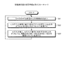
次に、データ収集部111の処理手順について説明する。図7は、データ収集部111の処理手順を示すフローチャートである。なお、データ収集部111は、blktraceコマンドを60秒間実行したことを条件として起動される。
Next, the processing procedure of the
図7に示すように、データ収集部111は、blktraceコマンドの実行により得られたトレース結果を取り出し、1GBオフセット単位すなわちセグメント単位で各セグメントのIO数を抽出する(ステップS1)。
As shown in FIG. 7, the
そして、データ収集部111は、セグメント毎にIO数が閾値pを上回るかどうかを判定し、pを上回ったセグメントの抽出を行う(ステップS2)。IO数が閾値pを上回ったセグメントは高負荷領域である。
Then, the
そして、データ収集部111は、抽出したセグメントに関して、隣接間距離がs以内となったセグメントを繋ぎ合わせていく(ステップS3)。そして、データ収集部111は、繋ぎ合わせたセグメントとその外側のsまでの範囲のセグメントをn_セグメントと定義し、抽出順にn_セグメント番号を採番する(ステップS4)。
Then, the
そして、データ収集部111は、n_セグメント毎にn_セグメント番号、セグメント範囲、IO数をタイムスタンプと共にデータベース112に書き込む(ステップS5)。
Then, the
このように、データ収集部111は、高負荷のセグメントに関して隣接間距離がs以内となったセグメントを繋ぎ合わせてn_セグメントを抽出することにより、高負荷のセグメントの近傍を適切に選択することができる。
As described above, the
次に、ワークロード分析部113の処理手順について説明する。図8は、ワークロード分析部113の処理手順を示すフローチャートである。図8に示すように、ワークロード分析部113は、データベース112から直近のタイムスタンプのn_セグメントについてIO数を取り出し(ステップS11)、IO数が多い順にn_セグメントを並べ替える(ステップS12)。 Next, a processing procedure of the workload analysis unit 113 will be described. FIG. 8 is a flowchart showing the processing procedure of the workload analysis unit 113. As illustrated in FIG. 8, the workload analysis unit 113 extracts the number of IOs for the n_segment of the latest time stamp from the database 112 (step S11), and rearranges the n_segments in descending order of the number of IOs (step S12).
そして、ワークロード分析部113は、各n_セグメントのIO数を合計することでio_allを求める(ステップS13)。そして、ワークロード分析部113は、以下の計算をmがmax_seg_numに到達するか、io_rateがio_rate_valueを超えるまで行う(ステップS14)。 Then, the workload analysis unit 113 calculates io_all by summing up the number of IOs of each n_segment (step S13). The workload analysis unit 113 performs the following calculation until m reaches max_seg_num or io_rate exceeds io_rate_value (step S14).
そして、io_rateがio_rate_valueを超えた場合には、ワークロード分析部113は、以下のステップS15〜ステップS22を行い、mがmax_seg_numに到達した場合には、ステップS23に移動する。すなわち、io_rateがio_rate_valueを超えた場合には、ワークロード分析部113は、対応するn_セグメント番号が連続して何回このトップkに入ったのかを候補テーブル114に記録する(ステップS15)。また、ワークロード分析部113は、前タイムスライスでトップkに入ったn_セグメントで今回トップkから外れたn_セグメントは、連続数をリセットする(ステップS16)。 When io_rate exceeds io_rate_value, the workload analysis unit 113 performs the following steps S15 to S22. When m reaches max_seg_num, the workload analysis unit 113 moves to step S23. That is, when io_rate exceeds io_rate_value, the workload analysis unit 113 records in the candidate table 114 how many times the corresponding n_segment number has entered this top k (step S15). In addition, the workload analysis unit 113 resets the number of consecutive n_segments that have entered the top k in the previous time slice and are out of the current top k (step S16).
そして、ワークロード分析部113は、連続数が所定の閾値t1を超えたn_セグメントを移動候補として抽出し、抽出したn_セグメントに含まれるセグメント数をnとし、n_セグメントのデータの移動時間Tiering_timeを計算する(ステップS17)。 Then, the workload analysis unit 113 extracts n_segments whose continuous number has exceeded a predetermined threshold value t 1 as a movement candidate, sets the number of segments included in the extracted n_segment as n, and the movement time Tiering_time of n_segment data Is calculated (step S17).
ここで、Tiering_time=seg_move_time×n+検出遅延であり、seg_move_timeは、1セグメントのデータをHDD300からSSD200へ移動するのに要する時間である。また、検出遅延は、移動候補の検出に要する時間であり、ここではデータの収集間隔の60秒とする。
Here, Tiering_time = seg_move_time × n + detection delay, and seg_move_time is the time required to move one segment of data from the
そして、ワークロード分析部113は、Tiering_timeとIOの集中率が高い状態が続くと期待される時間Life_ex_timeとを比較する(ステップS18)。そして、Tiering_timeがLife_ex_timeより小さくない場合には、ワークロード分析部113は、ステップS21へ進む。一方、Tiering_timeがLife_ex_timeより小さい場合には、ワークロード分析部113は、移動候補n_セグメントの情報を移動指示部116へ送付し、移動候補n_セグメントのデータのHDD300からSSD200への移動を指示する(ステップS19)。また、ワークロード分析部113は、SSD200へのデータの移動を指示したn_セグメントの情報を管理テーブル115に記録する(ステップS20)。
Then, the workload analysis unit 113 compares Tiering_time with the time Life_ex_time that is expected to continue with a high IO concentration rate (step S18). If Tiering_time is not smaller than Life_ex_time, the workload analysis unit 113 proceeds to step S21. On the other hand, when Tiering_time is smaller than Life_ex_time, the workload analysis unit 113 sends information on the movement candidate n_segment to the
そして、ワークロード分析部113は、トップkに入ったn_セグメント番号と管理テーブル115に登録されているn_セグメント番号の突合せを行う。そして、ワークロード分析部113は、管理テーブル115に登録されているn_セグメント毎にトップkに入らなかったn_セグメント番号の連続数を「+1」し、トップkに入っていたら連続数を「0」にリセットする(ステップS21)。 Then, the workload analysis unit 113 matches the n_segment number entered in the top k with the n_segment number registered in the management table 115. Then, the workload analysis unit 113 increments the number of consecutive n_segment numbers that did not enter the top k for each n_segment registered in the management table 115, and sets the number of consecutive numbers to “0” when it enters the top k. To "" (step S21).
そして、ワークロード分析部113は、管理テーブル115に登録されているn_セグメント番号毎に連続数が所定の閾値t2を超えているかどうかの判断を行う。そして、ワークロード分析部113は、連続数が所定の閾値t2を超えている場合は、n_セグメント番号を移動指示部116に送付してSSD200からHDD300へのデータの移動を指示する。また、ワークロード分析部113は、管理テーブル115に登録されているn_セグメントの情報を削除する(ステップS22)。そして、ワークロード分析部113は、60秒スリープし、ステップS11に戻る。
Then, the workload analysis unit 113 determines whether or not the continuous number exceeds a predetermined threshold t 2 for each n_segment number registered in the management table 115. Then, when the number of continuations exceeds a predetermined threshold t 2 , the workload analysis unit 113 sends the n_segment number to the
このように、ワークロード分析部113がIOの集中度が高いn_セグメントのデータをHDD300からSSD200に移動するように移動指示部116に指示することによって、ユーザはHDD300のデータに高速にアクセスすることができる。
As described above, the workload analysis unit 113 instructs the
次に、移動指示部116の処理手順について説明する。図9は、移動指示部116の処理手順を示すフローチャートである。図9に示すように、移動指示部116は、ワークロード分析部113からの移動指示を待つ(ステップS31)。
Next, the processing procedure of the
そして、移動指示があると、移動指示部116は、n_セグメント番号に属する各セグメントのボリューム上のオフセットをHDD300上のオフセットに変換する(ステップS32)。
When there is a movement instruction, the
そして、移動指示部116は、セグメント毎に、セグメント番号に対応するHDD300上のオフセットと、データの移動方向を階層ドライバ120に伝達する(ステップS33)。ここで、データの移動方向は、HDD300からSSD200か、又は、SSD200からHDD300である。そして、移動指示部116は、ステップS31に戻り、ワークロード分析部113からの移動指示を待つ。
Then, for each segment, the
このように、移動指示部116が各セグメントのボリューム上のオフセットをHDD300上のオフセットに変換することによって、階層ドライバ120はSSD200とHDD300との間でデータを移動することができる。
As described above, the
次に、移動指示を受け取ったときの階層ドライバ120の処理手順について図10A及び図10Bを用いて説明する。図10Aは、移動指示を受け取ったときの階層ドライバ120の処理手順を示すフローチャートである。
Next, the processing procedure of the
図10Aに示すように、階層ドライバ120は、移動指示部116からの移動指示を待ち(ステップS41)、移動指示があると、HDD300からSSD200へのデータの移動であるか否かを判定する(ステップS42)。
As shown in FIG. 10A, the
その結果、HDD300からSSD200へのデータの移動である場合には、階層ドライバ120は、移動を指示されたセグメントはSSD200へ移動済みであるか否かを判定し(ステップS43)、移動済みである場合には、ステップS41に戻る。
As a result, when the data is moved from the
一方、移動済みでない場合には、階層ドライバ120は、階層テーブル121内のHDDオフセットより「NULL」となっているエントリを探して、HDDオフセット情報と状態を登録する。登録する状態は、「Moving(HDD→SSD)」である。そして、階層ドライバ120は、HDD300からSSD200へのデータの転送指示をHDDドライバ140及びSSDドライバ130に行い(ステップS44)、ステップS41に戻る。
On the other hand, if it has not been moved, the
また、HDD300からSSD200へのデータの移動でない場合には、階層ドライバ120は、階層テーブル121内のHDDオフセットよりセグメントを探して、HDDオフセット情報と状態を登録する。登録する状態は、「Moving(SSD→HDD)」である。そして、階層ドライバ120は、SSD200からHDD300へのデータの転送指示をHDDドライバ140及びSSDドライバ130に行い(ステップS45)、ステップS41に戻る。
If the data is not moved from the
次に、転送指示後に転送完了通知を受け取ったときの階層ドライバ120の処理手順について説明する。図10Bは、転送指示後に転送完了通知を受け取ったときの階層ドライバ120の処理手順を示すフローチャートである。
Next, a processing procedure of the
図10Bに示すように、階層ドライバ120は、SSDドライバ130及びHDDドライバ140からの転送完了通知を待つ(ステップS51)。そして、階層ドライバ120は、転送が完了した階層テーブル121のエントリをHDDオフセットを用いて探し、状態がMoving(HDD→SSD)の時は状態を「allocated」に変更する。一方、階層ドライバ120は、状態がMoving(SSD→HDD)の時は状態を「free」に変更し、対応するHDDオフセットを「NULL」にする(ステップS52)。
As shown in FIG. 10B, the
このように、階層ドライバ120が階層テーブル121を用いてSSD200とHDD300との間でデータを転送することにより、IOが集中するセグメントのデータをSSD200に置くことができる。
As described above, the
次に、ユーザIOを受け取ったときの階層ドライバ120の処理手順について説明する。図11は、ユーザIOを受け取ったときの階層ドライバ120の処理手順を示すフローチャートである。
Next, a processing procedure of the
図11に示すように、階層ドライバ120は、ユーザIOの受信を待ち(ステップS61)、ユーザIOを受信すると、ユーザIOのオフセットと階層テーブル121に登録されている各オフセット+セグメントサイズの比較を行う(ステップS62)。
As shown in FIG. 11, the
そして、階層ドライバ120は、ユーザIOのオフセットと一致するオフセットが階層テーブル121に登録されているいずれかのセグメント内に存在し、かつ、そのセグメントの状態が「allocated」であるか否かを判定する(ステップS63)。
Then, the
その結果、ユーザIOのオフセットと一致するオフセットが存在し、かつ、状態が「allocated」である場合には、階層ドライバ120は、SSDドライバ130へIO命令を送付する(ステップS64)。一方、ユーザIOのオフセットと一致するオフセットが存在しないか、又は、状態が「allocated」でない場合には、階層ドライバ120は、HDDドライバ140へIO命令を送付する(ステップS65)。そして、階層ドライバ120は、ステップS61に戻り、ユーザIOの受信を待つ。
As a result, when there is an offset that matches the offset of the user IO and the state is “allocated”, the
上述してきたように、実施例では、データ収集部111が、IO数が閾値pを上回るセグメントに関して、隣接間距離s以内のセグメントを繋ぎ合わせ、繋ぎ合わせたセグメントとその外側のsまでの範囲をn_セグメントとして抽出する。そして、ワークロード分析部113が、n_セグメントを単位として、HDD300からSSD200にデータを移動する対象を決定する。したがって、階層ストレージ制御装置100は、高負荷領域の近傍を適切に選択してHDD300からSSD200にデータを移動することができ、HDD300へのアクセスを高速化することができる。
As described above, in the embodiment, the
なお、実施例では、抽出されたn_セグメントを時間変化させない場合について説明した。しかしながら、n_セグメントを時間変化させることもできる。そこで、n_セグメントの時間変化としてn_セグメントを拡大する場合について説明する。 In the embodiment, the case where the extracted n_segment is not changed with time has been described. However, the n_segment can be changed over time. Therefore, a case where the n_segment is enlarged as a time change of the n_segment will be described.
図12は、n_セグメントすなわち塊の拡大を行う階層ストレージ制御装置による動的階層制御を説明するための図である。塊の拡大を行う階層ストレージ制御装置は、拡張領域と、拡張領域とつながる別の拡張領域とを合わせて1つの拡張領域とみなす(A)。そして、塊の拡大を行う階層ストレージ制御装置は、拡張領域をSSDにデータを移動する移動領域とする。図12では、上下の破線の間の領域が移動領域である。 FIG. 12 is a diagram for explaining dynamic tier control by the tier storage control apparatus that performs n_segment, that is, chunk expansion. The hierarchical storage control apparatus that performs expansion of a chunk regards the extended area and another extended area connected to the extended area as one extended area (A). Then, the hierarchical storage control apparatus that performs the expansion of the chunk sets the expansion area as a movement area for moving data to the SSD. In FIG. 12, the area between the upper and lower broken lines is the moving area.
また、塊の拡大を行う階層ストレージ制御装置は、ある時点で塊領域を決定すると、時間の経過とともに塊領域の縮小は行わないが(B)、塊領域の拡大は行う(C)。また、塊の拡大を行う階層ストレージ制御装置は、一定時間網掛けの領域1が検出されないと、タイムアウトとみなして塊を終了とみなす。
In addition, when the hierarchical storage control apparatus that performs expansion of a lump determines a lump area at a certain point in time, the lump area is not reduced as time passes (B), but the lump area is expanded (C). In addition, if the hierarchical storage control apparatus that performs the expansion of the chunk does not detect the shaded
このような塊の拡大を行う階層ストレージ制御装置は、ワークロード分析部113の処理が一部異なる。具体的には、図8のステップS20において、ワークロード分析部113は、SSD200へのデータの移動を指示した今回のn_セグメントの情報と管理テーブル115の先頭セグメント番号とセグメント数を比較する。
The hierarchical storage control apparatus that performs such enlargement is partially different in the processing of the workload analysis unit 113. Specifically, in step S20 of FIG. 8, the workload analysis unit 113 compares the current n_segment information instructed to move data to the
そして、ワークロード分析部113は、今回のn_セグメントの情報が管理テーブル115のいずれかのエントリと先頭セグメント番号及びセグメント数が完全一致する場合は、ステップS21に進む。あるいは、管理テーブル115のいずれかのn_セグメントの領域が今回のn_セグメントの領域より広い場合も、ワークロード分析部113は、ステップ21に進む。 If the current n_segment information matches any entry in the management table 115 with the first segment number and the number of segments, the workload analysis unit 113 proceeds to step S21. Alternatively, if any n_segment area of the management table 115 is larger than the current n_segment area, the workload analysis unit 113 proceeds to step 21.
一方、管理テーブル115のいずれかのn_セグメントの領域が今回のn_セグメントの領域より狭い場合は、n_セグメントが拡大したので、ワークロード分析部113は、今回のn_セグメントの情報で管理テーブル115を更新し、ステップ21に進む。また、その他の場合には、ワークロード分析部113は、今回のn_セグメントの情報を新たなエントリとして管理テーブル115に登録し、ステップ21に進む。 On the other hand, if any n_segment area of the management table 115 is smaller than the current n_segment area, the n_segment has expanded, so the workload analysis unit 113 uses the current n_segment information to update the management table 115. Update and go to step 21. In other cases, the workload analysis unit 113 registers the current n_segment information as a new entry in the management table 115, and proceeds to step 21.
このように、ワークロード分析部113は、管理テーブル115のいずれかのn_セグメントの領域が今回のn_セグメントの領域より狭い場合に、今回のn_セグメントの情報で管理テーブル115を更新する。したがって、階層ストレージ制御装置は、n_セグメントを時間経過とともに拡大していくことができる。 As described above, when any n_segment area of the management table 115 is smaller than the current n_segment area, the workload analysis unit 113 updates the management table 115 with the current n_segment information. Therefore, the hierarchical storage control device can expand the n_segment as time passes.
また、階層ストレージ制御装置100は、同様の機能を有する階層ストレージ制御プログラムをコンピュータで実行することにより実現される。そこで、階層ストレージ制御プログラムを実行するコンピュータについて説明する。
The hierarchical
図13は、階層ストレージ制御プログラムを実行するコンピュータのハードウェア構成を示す図である。図13に示すように、コンピュータ400は、メインメモリ410と、CPU(Central Processing Unit)420と、LAN(Local Area Network)インタフェース430と、HDD(Hard Disk Drive)440とを有する。また、コンピュータ400は、スーパーIO(Input Output)450と、DVI(Digital Visual Interface)460と、ODD(Optical Disk Drive)470とを有する。
FIG. 13 is a diagram illustrating a hardware configuration of a computer that executes a hierarchical storage control program. As shown in FIG. 13, the
メインメモリ410は、プログラムやプログラムの実行途中結果などを記憶するメモリである。CPU420は、メインメモリ410からプログラムを読み出して実行する中央処理装置である。CPU420は、メモリコントローラを有するチップセットを含む。
The
LANインタフェース430は、コンピュータ400をLAN経由で他のコンピュータに接続するためのインタフェースである。HDD440は、プログラムやデータを格納するディスク装置であり、スーパーIO450は、マウスやキーボードなどの入力装置を接続するためのインタフェースである。DVI460は、液晶表示装置を接続するインタフェースであり、ODD470は、DVDの読み書きを行う装置である。
The
LANインタフェース430は、PCIエクスプレスによりCPU420に接続され、HDD440及びODD470は、SATA(Serial Advanced Technology Attachment)によりCPU420に接続される。スーパーIO450は、LPC(Low Pin Count)によりCPU420に接続される。
The
そして、コンピュータ400において実行される階層ストレージ制御プログラムは、DVDに記憶され、ODD470によってDVDから読み出されてコンピュータ400にインストールされる。あるいは、階層ストレージ制御プログラムは、LANインタフェース430を介して接続された他のコンピュータシステムのデータベースなどに記憶され、これらのデータベースから読み出されてコンピュータ400にインストールされる。そして、インストールされた階層ストレージ制御プログラムは、HDD440に記憶され、メインメモリ410に読み出されてCPU420によって実行される。
The hierarchical storage control program executed in the
また、本実施例では、SSD200とHDD300を用いた階層ストレージシステムについて説明したが、本発明はこれに限定されるものではなく、例えば、キャッシュメモリと主記憶装置を用いた階層記憶システムにも同様に適用することができる。すなわち、本発明は、不揮発性記憶装置の階層記憶システムだけでなく、揮発性記憶装置を含む階層記憶システムにも同様に適用することができる。
In this embodiment, the hierarchical storage system using the
以上の実施例を含む実施形態に関し、さらに以下の付記を開示する。 The following supplementary notes are further disclosed with respect to the embodiments including the above examples.
(付記1)ストレージ制御装置の制御プログラムにおいて、
前記ストレージ制御装置に、
第1の記憶装置で使用される領域を所定の大きさで分割した複数の単位領域について単位領域ごとに入出力数を集計させ、
前記入出力数が第1の閾値より大きな単位領域を高負荷領域として特定させ、
特定させた高負荷領域と所定の距離内にある単位領域を繋ぎ合わせた拡張領域と該拡張領域とつながる他の拡張領域とを合わせた領域を移動領域として特定させ、
特定させた移動領域のデータを第1の記憶装置より高速な第2の記憶装置に移動させることを特徴とするストレージ制御装置の制御プログラム。
(Supplementary note 1) In the control program of the storage control device,
In the storage control device,
The number of inputs / outputs for each unit area is tabulated for a plurality of unit areas obtained by dividing the area used in the first storage device by a predetermined size,
A unit area in which the number of inputs and outputs is larger than the first threshold is specified as a high load area;
An area that is a combination of an extended area that connects the identified high load area and a unit area within a predetermined distance and another extended area that is connected to the extended area is specified as a moving area;
A control program for a storage control device, characterized in that data of a specified movement area is moved to a second storage device that is faster than the first storage device.
(付記2)前記ストレージ制御装置の制御プログラムはさらに、前記移動領域が時間の経過とともに拡大した場合に、前記ストレージ制御装置に、拡大した移動領域のデータを第2の記憶装置に移動させることを特徴とする付記1記載のストレージ制御装置の制御プログラム。
(Supplementary Note 2) The control program of the storage control device may further cause the storage control device to move the data of the expanded movement area to the second storage device when the movement area is expanded with time. The storage control device control program according to
(付記3)前記ストレージ制御装置に、
複数の移動領域のうち、全体の入出力数に対して入出力数の和の比率が第2の閾値を超える移動領域のデータを第2の記憶装置に移動させることを特徴とする付記1記載のストレージ制御装置の制御プログラム。
(Appendix 3) To the storage control device,
(付記4)前記ストレージ制御装置に、
前記移動領域を一定の時間間隔で特定させ、
前記比率が所定の閾値を超える移動領域のうち、前記時間間隔で所定の回数連続して該閾値を超える移動領域のデータを第2の記憶装置に移動させることを特徴とする付記3記載のストレージ制御装置の制御プログラム。
(Appendix 4) In the storage control device,
Identifying the moving region at regular time intervals;
The storage according to
(付記5)前記ストレージ制御装置に、
前記回数連続して前記閾値を超える移動領域のうち、データを第2の記憶装置に移動させる時間より長い時間、入出力数が前記第1の閾値を超えると予想される移動領域のデータを第2の記憶装置に移動させることを特徴とする付記4記載のストレージ制御装置の制御プログラム。
(Supplementary Note 5) In the storage control device,
Of the moving areas that exceed the threshold value for the number of times, the data of the moving area that is expected to have the number of inputs and outputs exceeding the first threshold for a time longer than the time for moving the data to the second storage device. The storage control device control program according to appendix 4, wherein the storage control device is moved to the
(付記6)ストレージ制御装置の制御方法において、
前記ストレージ制御装置が、
第1の記憶装置で使用される領域を所定の大きさで分割した複数の単位領域について単位領域ごとに入出力数を集計し、
前記入出力数が第1の閾値より大きな単位領域を高負荷領域として特定し、
特定した高負荷領域と所定の距離内にある単位領域を繋ぎ合わせた拡張領域と該拡張領域とつながる他の拡張領域とを合わせた領域を移動領域として特定し、
特定した移動領域のデータを第1の記憶装置より高速な第2の記憶装置に移動することを特徴とするストレージ制御装置の制御方法。
(Supplementary Note 6) In the control method of the storage control device,
The storage controller is
The number of inputs / outputs for each unit area is aggregated for a plurality of unit areas obtained by dividing the area used in the first storage device by a predetermined size,
A unit area in which the number of inputs and outputs is larger than the first threshold is specified as a high load area,
An area that combines an extended area that connects the identified high load area and a unit area within a predetermined distance with another extended area that is connected to the extended area is specified as a moving area,
A control method for a storage control device, characterized in that data of a specified movement area is moved to a second storage device that is faster than the first storage device.
(付記7)第1の記憶装置で使用される領域を所定の大きさで分割した複数の単位領域について単位領域ごとに入出力数を集計する集計部と、
前記集計部により集計された入出力数が第1の閾値より大きな単位領域を高負荷領域として特定する高負荷領域特定部と、
前記高負荷領域特定部により特定された高負荷領域と所定の距離内にある単位領域を繋ぎ合わせた拡張領域と該拡張領域とつながる他の拡張領域とを合わせた領域を移動領域として特定する移動領域特定部と、
前記移動領域特定部により特定された移動領域のデータを第1の記憶装置より高速な第2の記憶装置に移動する移動部と
を備えたことを特徴とするストレージ制御装置。
(Additional remark 7) The total part which totals the input / output number for every unit area about the several unit area which divided | segmented the area | region used with a 1st memory | storage device by predetermined size,
A high-load area specifying unit that specifies a unit area in which the number of inputs / outputs counted by the counting unit is larger than a first threshold as a high-load area;
Movement that specifies an area that is a combination of an extended area that connects a high load area specified by the high load area specifying unit and a unit area that is within a predetermined distance and another extended area that is connected to the extended area as a moving area An area identification unit;
A storage control device comprising: a moving unit that moves data of the moving area specified by the moving area specifying unit to a second storage device that is faster than the first storage device.
(付記8)第1の記憶装置と、第1の記憶装置より高速な第2の記憶装置と、第1の記憶装置と第2の記憶装置との間のデータの移動を制御するストレージ制御装置とを備えた階層ストレージシステムにおいて、
前記ストレージ制御装置は、
第1の記憶装置で使用される領域を所定の大きさで分割した複数の単位領域について単位領域ごとに入出力数を集計する集計部と、
前記集計部により集計された入出力数が第1の閾値より大きな単位領域を高負荷領域として特定する高負荷領域特定部と、
前記高負荷領域特定部により特定された高負荷領域と所定の距離内にある単位領域を繋ぎ合わせた拡張領域と該拡張領域とつながる他の拡張領域とを合わせた領域を移動領域として特定する移動領域特定部と、
前記移動領域特定部により特定された移動領域のデータを第1の記憶装置より高速な第2の記憶装置に移動する移動部と
を備えたことを特徴とするストレージシステム。
(Supplementary Note 8) First storage device, second storage device faster than first storage device, and storage control device for controlling data movement between first storage device and second storage device In a tiered storage system with
The storage control device
A counting unit that counts the number of inputs and outputs for each unit area for a plurality of unit areas obtained by dividing the area used in the first storage device by a predetermined size;
A high-load area specifying unit that specifies a unit area in which the number of inputs / outputs counted by the counting unit is larger than a first threshold as a high-load area;
Movement that specifies an area that is a combination of an extended area that connects a high load area specified by the high load area specifying unit and a unit area that is within a predetermined distance and another extended area that is connected to the extended area as a moving area An area identification unit;
A storage system comprising: a moving unit that moves data of the moving area specified by the moving area specifying unit to a second storage device that is faster than the first storage device.
(付記9)ストレージ制御装置の制御プログラムにおいて、
前記ストレージ制御装置に、
第1の記憶装置で使用される領域を所定の大きさで分割した複数の単位領域について単位領域ごとに入出力数を集計させ、
前記入出力数が第1の閾値より大きな単位領域を高負荷領域として特定させ、
特定させた高負荷領域と所定の距離内にある単位領域を繋ぎ合わせた拡張領域と該拡張領域とつながる他の拡張領域とを合わせた領域を移動領域として特定させ、
特定させた移動領域のデータを第1の記憶装置より高速な第2の記憶装置に移動させることを特徴とするストレージ制御装置の制御プログラムを記憶したコンピュータ読み取り可能記憶媒体。
(Supplementary note 9) In the control program of the storage control device,
In the storage control device,
The number of inputs / outputs for each unit area is tabulated for a plurality of unit areas obtained by dividing the area used in the first storage device by a predetermined size,
A unit area in which the number of inputs and outputs is larger than the first threshold is specified as a high load area;
An area that is a combination of an extended area that connects the identified high load area and a unit area within a predetermined distance and another extended area that is connected to the extended area is specified as a moving area;
A computer-readable storage medium storing a control program for a storage control device, wherein data of a specified movement area is moved to a second storage device that is faster than the first storage device.
(付記10)メモリと該メモリに接続されたCPUとを有するストレージ制御装置において、
前記CPUに、
第1の記憶装置で使用される領域を所定の大きさで分割した複数の単位領域について単位領域ごとに入出力数を集計させ、
前記入出力数が第1の閾値より大きな単位領域を高負荷領域として特定させ、
特定させた高負荷領域と所定の距離内にある単位領域を繋ぎ合わせた拡張領域と該拡張領域とつながる他の拡張領域とを合わせた領域を移動領域として特定させ、
特定させた移動領域のデータを第1の記憶装置より高速な第2の記憶装置に移動させることを特徴とするストレージ制御装置。
(Supplementary Note 10) In a storage control device having a memory and a CPU connected to the memory,
In the CPU,
The number of inputs / outputs for each unit area is tabulated for a plurality of unit areas obtained by dividing the area used in the first storage device by a predetermined size,
A unit area in which the number of inputs and outputs is larger than the first threshold is specified as a high load area;
An area that is a combination of an extended area that connects the identified high load area and a unit area within a predetermined distance and another extended area that is connected to the extended area is specified as a moving area;
A storage control device that moves data of a specified movement area to a second storage device that is faster than the first storage device.
1 網掛けの領域
2 矢印
3 網掛けの正方形領域
100 階層ストレージ制御装置
110 階層管理部
111 データ収集部
112 データベース
113 ワークロード分析部
114 候補テーブル
115 管理テーブル
116 移動指示部
120 階層ドライバ
121 階層テーブル
130 SSDドライバ
140 HDDドライバ
400 コンピュータ
410 メインメモリ
420 CPU
430 LANインタフェース
440 HDD
450 スーパーIO
460 DVI
470 ODD
DESCRIPTION OF
430
450 Super IO
460 DVI
470 ODD
Claims (8)
前記ストレージ制御装置に、
第1の記憶装置で使用される領域を所定の大きさで分割した複数の単位領域について単位領域ごとに入出力数を集計させ、
前記入出力数が第1の閾値より大きな単位領域を高負荷領域として特定させ、
特定させた高負荷領域と所定の距離内にある単位領域をオフセットの上下両方向に繋ぎ合わせた拡張領域と該拡張領域とつながる他の拡張領域とを合わせた領域を移動領域として特定させ、
特定させた移動領域のデータを第1の記憶装置より高速な第2の記憶装置に移動させることを特徴とするストレージ制御装置の制御プログラム。 In the control program of the storage control device,
In the storage control device,
The number of inputs / outputs for each unit area is tabulated for a plurality of unit areas obtained by dividing the area used in the first storage device by a predetermined size,
A unit area in which the number of inputs and outputs is larger than the first threshold is specified as a high load area;
An area that is a combination of an extended area obtained by connecting the specified high load area and a unit area within a predetermined distance in both the upper and lower directions of the offset and another extended area connected to the extended area is specified as a moving area,
A control program for a storage control device, characterized in that data of a specified movement area is moved to a second storage device that is faster than the first storage device.
前記移動領域が時間の経過とともに拡大した場合に、前記ストレージ制御装置に、拡大した移動領域のデータを第2の記憶装置に移動させることを特徴とする請求項1記載のストレージ制御装置の制御プログラム。 The storage control device control program further includes:
2. The storage control device control program according to claim 1, wherein when the moving area expands with time, the storage control apparatus moves data of the expanded moving area to a second storage device. .
複数の移動領域のうち、全体の入出力数に対して多い方からの入出力数の和の比率が第2の閾値を超える複数の移動領域のデータを第2の記憶装置に移動させることを特徴とする請求項1記載のストレージ制御装置の制御プログラム。 In the storage control device,
Of the plurality of movement areas, the data of the plurality of movement areas in which the ratio of the sum of the number of input / outputs from the larger one to the total number of input / outputs exceeds the second threshold is moved to the second storage device. The storage control apparatus control program according to claim 1, wherein:
前記移動領域を一定の時間間隔で特定させ、
前記比率が所定の閾値を超える移動領域のうち、前記時間間隔で所定の回数連続して該閾値を超える移動領域のデータを第2の記憶装置に移動させることを特徴とする請求項3記載のストレージ制御装置の制御プログラム。 In the storage control device,
Identifying the moving region at regular time intervals;
4. The data in a moving area in which the ratio exceeds a predetermined threshold among the moving areas in which the ratio exceeds a predetermined threshold is moved to the second storage device continuously for a predetermined number of times at the time interval. Storage controller control program.
前記回数連続して前記閾値を超える移動領域のうち、データを第2の記憶装置に移動させる時間より長い時間、入出力数が前記第1の閾値を超えると予想される移動領域のデータを第2の記憶装置に移動させることを特徴とする請求項4記載のストレージ制御装置の制御プログラム。 In the storage control device,
Of the moving areas that exceed the threshold value for the number of times, the data of the moving area that is expected to have the number of inputs and outputs exceeding the first threshold for a time longer than the time for moving the data to the second storage device. 5. The storage control device control program according to claim 4, wherein the storage control device is moved to a second storage device.
前記ストレージ制御装置が、
第1の記憶装置で使用される領域を所定の大きさで分割した複数の単位領域について単位領域ごとに入出力数を集計し、
前記入出力数が第1の閾値より大きな単位領域を高負荷領域として特定し、
特定した高負荷領域と所定の距離内にある単位領域をオフセットの上下両方向に繋ぎ合わせた拡張領域と該拡張領域とつながる他の拡張領域とを合わせた領域を移動領域として特定し、
特定した移動領域のデータを第1の記憶装置より高速な第2の記憶装置に移動することを特徴とするストレージ制御装置の制御方法。 In the control method of the storage control device,
The storage controller is
The number of inputs / outputs for each unit area is aggregated for a plurality of unit areas obtained by dividing the area used in the first storage device by a predetermined size,
A unit area in which the number of inputs and outputs is larger than the first threshold is specified as a high load area,
Specify the area that is a combination of the extended area that connects the specified high load area and the unit area that is within a predetermined distance in both the upper and lower directions of the offset and the other extended area that is connected to the extended area as the moving area,
A control method for a storage control device, characterized in that data of a specified movement area is moved to a second storage device that is faster than the first storage device.
前記集計部により集計された入出力数が第1の閾値より大きな単位領域を高負荷領域として特定する高負荷領域特定部と、
前記高負荷領域特定部により特定された高負荷領域と所定の距離内にある単位領域をオフセットの上下両方向に繋ぎ合わせた拡張領域と該拡張領域とつながる他の拡張領域とを合わせた領域を移動領域として特定する移動領域特定部と、
前記移動領域特定部により特定された移動領域のデータを第1の記憶装置より高速な第2の記憶装置に移動する移動部と
を備えたことを特徴とするストレージ制御装置。 A counting unit that counts the number of inputs and outputs for each unit area for a plurality of unit areas obtained by dividing the area used in the first storage device by a predetermined size;
A high-load area specifying unit that specifies a unit area in which the number of inputs / outputs counted by the counting unit is larger than a first threshold as a high-load area;
Move the area that combines the high load area specified by the high load area specifying unit and the extended area that connects unit areas within a predetermined distance in both the upper and lower directions of the offset and the other extended area that is connected to the extended area. A moving area specifying unit that specifies the area;
A storage control device comprising: a moving unit that moves data of the moving area specified by the moving area specifying unit to a second storage device that is faster than the first storage device.
前記ストレージ制御装置は、
第1の記憶装置で使用される領域を所定の大きさで分割した複数の単位領域について単位領域ごとに入出力数を集計する集計部と、
前記集計部により集計された入出力数が第1の閾値より大きな単位領域を高負荷領域として特定する高負荷領域特定部と、
前記高負荷領域特定部により特定された高負荷領域と所定の距離内にある単位領域をオフセットの上下両方向に繋ぎ合わせた拡張領域と該拡張領域とつながる他の拡張領域とを合わせた領域を移動領域として特定する移動領域特定部と、
前記移動領域特定部により特定された移動領域のデータを第1の記憶装置より高速な第2の記憶装置に移動する移動部と
を備えたことを特徴とするストレージシステム。 A first storage device; a second storage device that is faster than the first storage device; and a storage control device that controls data movement between the first storage device and the second storage device. In the storage system,
The storage control device
A counting unit that counts the number of inputs and outputs for each unit area for a plurality of unit areas obtained by dividing the area used in the first storage device by a predetermined size;
A high-load area specifying unit that specifies a unit area in which the number of inputs / outputs counted by the counting unit is larger than a first threshold as a high-load area;
Move the area that combines the high load area specified by the high load area specifying unit and the extended area that connects unit areas within a predetermined distance in both the upper and lower directions of the offset and the other extended area that is connected to the extended area. A moving area specifying unit that specifies the area;
A storage system comprising: a moving unit that moves data of the moving area specified by the moving area specifying unit to a second storage device that is faster than the first storage device.
Priority Applications (2)
| Application Number | Priority Date | Filing Date | Title |
|---|---|---|---|
| JP2013065204A JP6086007B2 (en) | 2013-03-26 | 2013-03-26 | Storage control device control program, storage control device control method, storage control device, and storage system |
| US14/157,596 US9158463B2 (en) | 2013-03-26 | 2014-01-17 | Control program of storage control device, control method of storage control device and storage control device |
Applications Claiming Priority (1)
| Application Number | Priority Date | Filing Date | Title |
|---|---|---|---|
| JP2013065204A JP6086007B2 (en) | 2013-03-26 | 2013-03-26 | Storage control device control program, storage control device control method, storage control device, and storage system |
Publications (2)
| Publication Number | Publication Date |
|---|---|
| JP2014191503A JP2014191503A (en) | 2014-10-06 |
| JP6086007B2 true JP6086007B2 (en) | 2017-03-01 |
Family
ID=51622010
Family Applications (1)
| Application Number | Title | Priority Date | Filing Date |
|---|---|---|---|
| JP2013065204A Active JP6086007B2 (en) | 2013-03-26 | 2013-03-26 | Storage control device control program, storage control device control method, storage control device, and storage system |
Country Status (2)
| Country | Link |
|---|---|
| US (1) | US9158463B2 (en) |
| JP (1) | JP6086007B2 (en) |
Families Citing this family (8)
| Publication number | Priority date | Publication date | Assignee | Title |
|---|---|---|---|---|
| JP6497233B2 (en) | 2015-06-19 | 2019-04-10 | 富士通株式会社 | Storage control device, storage control program, and storage control method |
| JP6572756B2 (en) | 2015-11-27 | 2019-09-11 | 富士通株式会社 | Information processing apparatus, storage control program, and storage control method |
| CN108089814B (en) * | 2016-11-23 | 2021-04-06 | 中移(苏州)软件技术有限公司 | Data storage method and device |
| JP6955142B2 (en) | 2017-03-17 | 2021-10-27 | 富士通株式会社 | Information processing device, storage control method and storage control program |
| US10101922B1 (en) | 2017-05-31 | 2018-10-16 | International Business Machines Corporation | Addressing usage of shared SSD resources in volatile and unpredictable operating environments |
| US11199995B2 (en) | 2019-11-19 | 2021-12-14 | Micron Technology, Inc. | Time to live for load commands |
| US11243804B2 (en) * | 2019-11-19 | 2022-02-08 | Micron Technology, Inc. | Time to live for memory access by processors |
| CN113885795B (en) * | 2021-09-23 | 2024-01-19 | 惠州Tcl移动通信有限公司 | Data storage method, device, terminal equipment and storage medium |
Family Cites Families (12)
| Publication number | Priority date | Publication date | Assignee | Title |
|---|---|---|---|---|
| JPH06119244A (en) | 1992-04-20 | 1994-04-28 | Hitachi Ltd | Disk controller and cache control method |
| JP4104283B2 (en) | 2000-12-19 | 2008-06-18 | 株式会社日立製作所 | Storage subsystem and information processing system |
| JP2002207620A (en) | 2001-01-10 | 2002-07-26 | Toshiba Corp | File system and data caching method of the same system |
| JP2008299559A (en) * | 2007-05-31 | 2008-12-11 | Hitachi Ltd | Storage system and data transfer method for storage system |
| US8423604B2 (en) * | 2008-08-29 | 2013-04-16 | R. Brent Johnson | Secure virtual tape management system with balanced storage and multi-mirror options |
| US8874867B2 (en) * | 2008-11-21 | 2014-10-28 | Lsi Corporation | Identification and containment of performance hot-spots in virtual volumes |
| JP5716537B2 (en) * | 2011-05-20 | 2015-05-13 | 日本電気株式会社 | Storage medium control device, storage device, storage medium control method, and program |
| US9052830B1 (en) * | 2011-06-30 | 2015-06-09 | Emc Corporation | Techniques for automated evaluation and movement of data between storage tiers for thin devices |
| EP2766803B1 (en) * | 2011-10-12 | 2022-12-07 | Tata Consultancy Services Limited | A method and system for consolidating a plurality of heterogeneous storage systems in a data center |
| US8886781B2 (en) * | 2011-12-13 | 2014-11-11 | Microsoft Corporation | Load balancing in cluster storage systems |
| US8909859B2 (en) * | 2012-03-01 | 2014-12-09 | HGST Netherlands B.V. | Implementing large block random write hot spare SSD for SMR RAID |
| JP6065642B2 (en) * | 2013-02-25 | 2017-01-25 | 富士通株式会社 | Storage control program, storage control device, storage system, and storage control method |
-
2013
- 2013-03-26 JP JP2013065204A patent/JP6086007B2/en active Active
-
2014
- 2014-01-17 US US14/157,596 patent/US9158463B2/en active Active
Also Published As
| Publication number | Publication date |
|---|---|
| US20140297971A1 (en) | 2014-10-02 |
| US9158463B2 (en) | 2015-10-13 |
| JP2014191503A (en) | 2014-10-06 |
Similar Documents
| Publication | Publication Date | Title |
|---|---|---|
| JP6086007B2 (en) | Storage control device control program, storage control device control method, storage control device, and storage system | |
| JP5629919B2 (en) | How to place virtual volume hotspots in a storage pool using ongoing load measurement and ranking | |
| US20190138517A1 (en) | Hot-Spot Adaptive Garbage Collection | |
| JP4699837B2 (en) | Storage system, management computer and data migration method | |
| JP6065642B2 (en) | Storage control program, storage control device, storage system, and storage control method | |
| Li et al. | Mining block correlations to improve storage performance | |
| US20180181338A1 (en) | Information processing apparatus, information processing system and information processing method | |
| JP6299169B2 (en) | Storage device, storage device control method, and storage device control program | |
| WO2016107390A1 (en) | Method and device for managing magnetic disk file | |
| CN106486167A (en) | Improve the method and system that flash memory is removed | |
| Xia et al. | FARMER: A novel approach to file access correlation mining and evaluation reference model for optimizing peta-scale file system performance | |
| US20200089425A1 (en) | Information processing apparatus and non-transitory computer-readable recording medium having stored therein information processing program | |
| Bhimani et al. | FIOS: Feature based I/O stream identification for improving endurance of multi-stream SSDs | |
| US9460001B2 (en) | Systems and methods for identifying access rate boundaries of workloads | |
| JP6260384B2 (en) | Storage control device, control program, and control method | |
| Shafaei et al. | Write Amplification Reduction in {Flash-Based}{SSDs} Through {Extent-Based} Temperature Identification | |
| US20190324677A1 (en) | Information processing apparatus | |
| Oe et al. | On-The-Fly Automated Storage Tiering (OTF-AST) | |
| US10168944B2 (en) | Information processing apparatus and method executed by an information processing apparatus | |
| US10725710B2 (en) | Hierarchical storage device, hierarchical storage control device, computer-readable recording medium having hierarchical storage control program recorded thereon, and hierarchical storage control method | |
| JP7234704B2 (en) | Information processing device and information processing program | |
| JP6497233B2 (en) | Storage control device, storage control program, and storage control method | |
| Paulson et al. | Page Replacement Algorithms–Challenges and Trends | |
| Won et al. | Intelligent storage: Cross-layer optimization for soft real-time workload | |
| US10320907B2 (en) | Multi-stage prefetching to exploit long-term future data access sequence knowledge |
Legal Events
| Date | Code | Title | Description |
|---|---|---|---|
| A621 | Written request for application examination |
Free format text: JAPANESE INTERMEDIATE CODE: A621 Effective date: 20151106 |
|
| A977 | Report on retrieval |
Free format text: JAPANESE INTERMEDIATE CODE: A971007 Effective date: 20160930 |
|
| A131 | Notification of reasons for refusal |
Free format text: JAPANESE INTERMEDIATE CODE: A131 Effective date: 20161004 |
|
| A521 | Written amendment |
Free format text: JAPANESE INTERMEDIATE CODE: A523 Effective date: 20161128 |
|
| TRDD | Decision of grant or rejection written | ||
| A01 | Written decision to grant a patent or to grant a registration (utility model) |
Free format text: JAPANESE INTERMEDIATE CODE: A01 Effective date: 20170104 |
|
| A61 | First payment of annual fees (during grant procedure) |
Free format text: JAPANESE INTERMEDIATE CODE: A61 Effective date: 20170117 |
|
| R150 | Certificate of patent or registration of utility model |
Ref document number: 6086007 Country of ref document: JP Free format text: JAPANESE INTERMEDIATE CODE: R150 |