JP6084184B2 - User terminal, radio communication system, and radio communication method - Google Patents
User terminal, radio communication system, and radio communication method Download PDFInfo
- Publication number
- JP6084184B2 JP6084184B2 JP2014163017A JP2014163017A JP6084184B2 JP 6084184 B2 JP6084184 B2 JP 6084184B2 JP 2014163017 A JP2014163017 A JP 2014163017A JP 2014163017 A JP2014163017 A JP 2014163017A JP 6084184 B2 JP6084184 B2 JP 6084184B2
- Authority
- JP
- Japan
- Prior art keywords
- user terminal
- cell
- transmission
- antenna
- antenna selection
- Prior art date
- Legal status (The legal status is an assumption and is not a legal conclusion. Google has not performed a legal analysis and makes no representation as to the accuracy of the status listed.)
- Active
Links
- 238000004891 communication Methods 0.000 title claims description 47
- 238000000034 method Methods 0.000 title claims description 23
- 230000005540 biological transmission Effects 0.000 claims description 158
- 230000009977 dual effect Effects 0.000 claims description 36
- 238000012545 processing Methods 0.000 description 59
- 230000007274 generation of a signal involved in cell-cell signaling Effects 0.000 description 21
- 238000013507 mapping Methods 0.000 description 15
- 230000011664 signaling Effects 0.000 description 11
- 230000002776 aggregation Effects 0.000 description 9
- 238000004220 aggregation Methods 0.000 description 9
- 238000010586 diagram Methods 0.000 description 7
- 230000006870 function Effects 0.000 description 6
- 230000001360 synchronised effect Effects 0.000 description 5
- 238000005259 measurement Methods 0.000 description 4
- 238000012790 confirmation Methods 0.000 description 3
- 238000007726 management method Methods 0.000 description 3
- 239000013307 optical fiber Substances 0.000 description 3
- 238000012937 correction Methods 0.000 description 2
- 238000010295 mobile communication Methods 0.000 description 2
- 230000008569 process Effects 0.000 description 2
- 238000011144 upstream manufacturing Methods 0.000 description 2
- 101000741965 Homo sapiens Inactive tyrosine-protein kinase PRAG1 Proteins 0.000 description 1
- 102100038659 Inactive tyrosine-protein kinase PRAG1 Human genes 0.000 description 1
- 230000008901 benefit Effects 0.000 description 1
- 239000000969 carrier Substances 0.000 description 1
- 230000000694 effects Effects 0.000 description 1
- 238000005516 engineering process Methods 0.000 description 1
- 230000007774 longterm Effects 0.000 description 1
- 238000012986 modification Methods 0.000 description 1
- 230000004048 modification Effects 0.000 description 1
- 238000010187 selection method Methods 0.000 description 1
- 230000008054 signal transmission Effects 0.000 description 1
Images


Classifications
-
- H—ELECTRICITY
- H04—ELECTRIC COMMUNICATION TECHNIQUE
- H04B—TRANSMISSION
- H04B7/00—Radio transmission systems, i.e. using radiation field
- H04B7/02—Diversity systems; Multi-antenna system, i.e. transmission or reception using multiple antennas
- H04B7/022—Site diversity; Macro-diversity
- H04B7/024—Co-operative use of antennas of several sites, e.g. in co-ordinated multipoint or co-operative multiple-input multiple-output [MIMO] systems
-
- H—ELECTRICITY
- H04—ELECTRIC COMMUNICATION TECHNIQUE
- H04B—TRANSMISSION
- H04B7/00—Radio transmission systems, i.e. using radiation field
- H04B7/02—Diversity systems; Multi-antenna system, i.e. transmission or reception using multiple antennas
- H04B7/04—Diversity systems; Multi-antenna system, i.e. transmission or reception using multiple antennas using two or more spaced independent antennas
- H04B7/06—Diversity systems; Multi-antenna system, i.e. transmission or reception using multiple antennas using two or more spaced independent antennas at the transmitting station
- H04B7/0602—Diversity systems; Multi-antenna system, i.e. transmission or reception using multiple antennas using two or more spaced independent antennas at the transmitting station using antenna switching
- H04B7/0604—Diversity systems; Multi-antenna system, i.e. transmission or reception using multiple antennas using two or more spaced independent antennas at the transmitting station using antenna switching with predefined switching scheme
-
- H—ELECTRICITY
- H04—ELECTRIC COMMUNICATION TECHNIQUE
- H04B—TRANSMISSION
- H04B7/00—Radio transmission systems, i.e. using radiation field
- H04B7/02—Diversity systems; Multi-antenna system, i.e. transmission or reception using multiple antennas
- H04B7/04—Diversity systems; Multi-antenna system, i.e. transmission or reception using multiple antennas using two or more spaced independent antennas
- H04B7/06—Diversity systems; Multi-antenna system, i.e. transmission or reception using multiple antennas using two or more spaced independent antennas at the transmitting station
- H04B7/0602—Diversity systems; Multi-antenna system, i.e. transmission or reception using multiple antennas using two or more spaced independent antennas at the transmitting station using antenna switching
- H04B7/0608—Antenna selection according to transmission parameters
- H04B7/061—Antenna selection according to transmission parameters using feedback from receiving side
-
- H—ELECTRICITY
- H04—ELECTRIC COMMUNICATION TECHNIQUE
- H04L—TRANSMISSION OF DIGITAL INFORMATION, e.g. TELEGRAPHIC COMMUNICATION
- H04L5/00—Arrangements affording multiple use of the transmission path
- H04L5/0001—Arrangements for dividing the transmission path
- H04L5/0003—Two-dimensional division
- H04L5/0005—Time-frequency
- H04L5/0007—Time-frequency the frequencies being orthogonal, e.g. OFDM(A), DMT
- H04L5/001—Time-frequency the frequencies being orthogonal, e.g. OFDM(A), DMT the frequencies being arranged in component carriers
-
- H—ELECTRICITY
- H04—ELECTRIC COMMUNICATION TECHNIQUE
- H04L—TRANSMISSION OF DIGITAL INFORMATION, e.g. TELEGRAPHIC COMMUNICATION
- H04L5/00—Arrangements affording multiple use of the transmission path
- H04L5/003—Arrangements for allocating sub-channels of the transmission path
- H04L5/0032—Distributed allocation, i.e. involving a plurality of allocating devices, each making partial allocation
- H04L5/0035—Resource allocation in a cooperative multipoint environment
-
- H—ELECTRICITY
- H04—ELECTRIC COMMUNICATION TECHNIQUE
- H04L—TRANSMISSION OF DIGITAL INFORMATION, e.g. TELEGRAPHIC COMMUNICATION
- H04L5/00—Arrangements affording multiple use of the transmission path
- H04L5/0091—Signaling for the administration of the divided path
- H04L5/0096—Indication of changes in allocation
- H04L5/0098—Signalling of the activation or deactivation of component carriers, subcarriers or frequency bands
-
- H—ELECTRICITY
- H04—ELECTRIC COMMUNICATION TECHNIQUE
- H04W—WIRELESS COMMUNICATION NETWORKS
- H04W16/00—Network planning, e.g. coverage or traffic planning tools; Network deployment, e.g. resource partitioning or cells structures
- H04W16/24—Cell structures
- H04W16/32—Hierarchical cell structures
-
- H—ELECTRICITY
- H04—ELECTRIC COMMUNICATION TECHNIQUE
- H04W—WIRELESS COMMUNICATION NETWORKS
- H04W72/00—Local resource management
- H04W72/04—Wireless resource allocation
-
- H—ELECTRICITY
- H04—ELECTRIC COMMUNICATION TECHNIQUE
- H04W—WIRELESS COMMUNICATION NETWORKS
- H04W88/00—Devices specially adapted for wireless communication networks, e.g. terminals, base stations or access point devices
- H04W88/02—Terminal devices
-
- H—ELECTRICITY
- H04—ELECTRIC COMMUNICATION TECHNIQUE
- H04L—TRANSMISSION OF DIGITAL INFORMATION, e.g. TELEGRAPHIC COMMUNICATION
- H04L5/00—Arrangements affording multiple use of the transmission path
- H04L5/0001—Arrangements for dividing the transmission path
- H04L5/0014—Three-dimensional division
- H04L5/0023—Time-frequency-space
-
- H—ELECTRICITY
- H04—ELECTRIC COMMUNICATION TECHNIQUE
- H04W—WIRELESS COMMUNICATION NETWORKS
- H04W76/00—Connection management
- H04W76/10—Connection setup
- H04W76/15—Setup of multiple wireless link connections
Landscapes
- Engineering & Computer Science (AREA)
- Signal Processing (AREA)
- Computer Networks & Wireless Communication (AREA)
- Mobile Radio Communication Systems (AREA)
Description
本発明は、次世代移動通信システムにおけるユーザ端末、無線基地局及び無線通信方法に関する。 The present invention relates to a user terminal, a radio base station, and a radio communication method in a next generation mobile communication system.
UMTS(Universal Mobile Telecommunications System)ネットワークにおいて、さらなる高速データレート、低遅延などを目的としてロングタームエボリューション(LTE:Long Term Evolution)が仕様化された(非特許文献1)。 In the UMTS (Universal Mobile Telecommunications System) network, Long Term Evolution (LTE) has been specified for the purpose of higher data rate and low delay (Non-patent Document 1).
LTEではマルチアクセス方式として、下り回線(下りリンク)にOFDMA(Orthogonal Frequency Division Multiple Access)をベースとした方式を用い、上り回線(上りリンク)にSC−FDMA(Single Carrier Frequency Division Multiple Access)をベースとした方式を用いている。 LTE uses a multi-access scheme based on OFDMA (Orthogonal Frequency Division Multiple Access) for the downlink (downlink) and SC-FDMA (single carrier frequency division multiple access) for the uplink (uplink). Is used.
LTEからのさらなる広帯域化及び高速化を目的として、LTEアドバンストと呼ばれるLTEの後継システム(LTE−Aとも呼ばれる)が検討され、LTE Rel.10/11として仕様化されている。Rel.10/11のシステム帯域は、LTEシステムのシステム帯域を一単位とする少なくとも1つのコンポーネントキャリア(CC:Component Carrier)を含んでいる。このように、複数のCCを集めて広帯域化することをキャリアアグリゲーション(CA:Carrier Aggregation)という。 For the purpose of further broadbanding and speeding up from LTE, a successor system of LTE called LTE Advanced (also called LTE-A) has been studied, and LTE Rel. It is specified as 10/11. Rel. The 10/11 system band includes at least one component carrier (CC) having the system band of the LTE system as one unit. In this manner, collecting a plurality of CCs to increase the bandwidth is referred to as carrier aggregation (CA).
LTEのさらなる後継システムであるRel.12においては、複数のセルが異なる周波数帯(キャリア)で用いられる様々なシナリオが検討されている。複数のセルを形成する無線基地局が実質的に同一の場合には、上述のCAを適用可能である。一方、各セルを形成する無線基地局が完全に異なる場合には、デュアルコネクティビティ(DC:Dual Connectivity)を適用することが検討されている。 Rel., A further successor system of LTE. 12, various scenarios in which a plurality of cells are used in different frequency bands (carriers) are being studied. When the radio base stations forming a plurality of cells are substantially the same, the above-described CA can be applied. On the other hand, when the radio base stations forming each cell are completely different, it has been studied to apply dual connectivity (DC).
LTEシステムにおける上りリンク(UL)では、アンテナスイッチングを利用した送信ダイバーシチ(アンテナ選択ダイバーシチ)法が規定されている。アンテナスイッチングを用いた送信ダイバーシチは、ユーザ端末がUL送信に用いるアンテナ(アンテナポートとも呼ぶ)を切り替えることにより、送信品質を向上することを指す。UL送信としては、ULデータ(PUSCH信号)やUL参照信号(SRS:Sounding Reference Signal)等が挙げられる。 In uplink (UL) in the LTE system, a transmission diversity (antenna selection diversity) method using antenna switching is defined. Transmission diversity using antenna switching refers to improving transmission quality by switching an antenna (also referred to as an antenna port) used by a user terminal for UL transmission. Examples of UL transmission include UL data (PUSCH signal), UL reference signal (SRS: Sounding Reference Signal), and the like.
LTEシステムでは、開ループ(open-loop)と閉ループ(closed-loop)に対してそれぞれアンテナスイッチングを利用した送信ダイバーシチ法がサポートされている。開ループアンテナ選択では、ユーザ端末及び/又は無線基地局がUL送信に用いる送信アンテナを適宜選択することにより、アンテナ選択ダイバーシチ利得を得ることができる。 In the LTE system, a transmission diversity method using antenna switching is supported for each of an open-loop and a closed-loop. In the open loop antenna selection, the antenna selection diversity gain can be obtained by appropriately selecting the transmission antenna used by the user terminal and / or the radio base station for UL transmission.
一方、閉ループアンテナスイッチングでは、ULのチャネル品質等に基づいて無線基地局が選択したアンテナポートをUL送信用のアンテナポートとしてユーザ端末に通知し、ユーザ端末が通知されたアンテナポートを選択してUL送信を行う。これにより、開ループアンテナスイッチングと比較してより高いダイバーシチ利得を得ることができる。例えば、無線基地局は、ユーザ端末から送信されるチャネル測定用の参照信号(例えば、SRS)に基づいてULのチャネル状態を把握し、ユーザ端末が利用するアンテナを指示することができる。アンテナ選択(UE transmit antenna selection)が設定されているユーザ端末は、無線基地局からの指示に基づいて所定のアンテナポートを選択することができる。 On the other hand, in closed-loop antenna switching, the antenna port selected by the radio base station based on the UL channel quality or the like is notified to the user terminal as an antenna port for UL transmission, and the user terminal selects the notified antenna port to select the UL. Send. Thereby, a higher diversity gain can be obtained as compared with open-loop antenna switching. For example, the radio base station can grasp the UL channel state based on a channel measurement reference signal (for example, SRS) transmitted from the user terminal, and can instruct the antenna used by the user terminal. A user terminal for which antenna selection (UE transmit antenna selection) is set can select a predetermined antenna port based on an instruction from the radio base station.
LTE−Aシステムで規定されているキャリアアグリゲーション(CA)では、アンテナ選択(UE transmit antenna selection)を適用する場合に、異なるセル(CCとも呼ぶ)で共通の送信アンテナを利用する。これにより、ユーザ端末は、複数のセルと接続する場合であっても、単一のRF回路等で通信を行うことができるなど、ベースバンド(BB)およびRFを含めたユーザ端末の回路規模の増大を抑制することが可能となる。 In carrier aggregation (CA) defined in the LTE-A system, when antenna selection (UE transmit antenna selection) is applied, a common transmission antenna is used in different cells (also referred to as CC). Thereby, even when the user terminal is connected to a plurality of cells, the user terminal circuit scale including the baseband (BB) and the RF can be communicated with a single RF circuit or the like. The increase can be suppressed.
しかし、デュアルコネクティビティ(DC)のように、ユーザ端末が複数の無線基地局に接続する場合、当該複数の無線基地局間ではスケジューリングが独立しており、さらに複数の無線基地局が必ずしも同期しているとは限らず非同期で運用されることも想定される。そのため、DCにおいてユーザ端末がアンテナ選択を適用する場合、CAと同様に全てのCCで同一の送信アンテナを選択することが難しくなる。 However, when a user terminal connects to a plurality of radio base stations as in dual connectivity (DC), scheduling is independent among the plurality of radio base stations, and the plurality of radio base stations are not necessarily synchronized. It is not limited to this, and it is assumed that it will be operated asynchronously. Therefore, when the user terminal applies antenna selection in DC, it is difficult to select the same transmission antenna in all CCs as in CA.
本発明はかかる点に鑑みてなされたものであり、ユーザ端末がデュアルコネクティビティ(DC)を適用して複数の無線基地局と接続する場合であっても、ユーザ端末におけるアンテナ選択を適切に制御することができるユーザ端末、無線基地局及び無線通信方法を提供することを目的の1つとする。 The present invention has been made in view of the above points, and appropriately controls antenna selection in a user terminal even when the user terminal connects to a plurality of radio base stations by applying dual connectivity (DC). It is an object to provide a user terminal, a radio base station, and a radio communication method that can be used.
本発明のユーザ端末の一態様は、1つ以上のセルから構成されるセルグループをそれぞれ設定する複数の無線基地局とデュアルコネクティビティを用いた通信をサポートするユーザ端末であって、1又は複数のセルグループに対して、UL信号を送信する送信部と、前記UL信号の送信に利用するアンテナの選択を制御する制御部と、を有し、前記制御部は、サービングセルに対するアンテナ選択(UE transmit antenna selection)が設定される場合に、複数のセルグループが設定されないと判断して開ループアンテナ選択及び/又は閉ループアンテナ選択を制御することを特徴とする。
One aspect of the user terminal of the present invention is a user terminal that supports communication using dual connectivity with a plurality of radio base stations that respectively set a cell group composed of one or more cells. A cell group includes a transmission unit that transmits a UL signal and a control unit that controls selection of an antenna used for transmission of the UL signal. The control unit selects an antenna for a serving cell (UE transmit antenna). If the selection) is set, and controls the open-loop antenna selection and / or closed-loop antenna selection is determined that a plurality of cell groups is not set.
本発明によれば、ユーザ端末がデュアルコネクティビティ(DC)を適用して複数の無線基地局と接続する場合であっても、ユーザ端末におけるアンテナ選択を適切に制御することができる。 ADVANTAGE OF THE INVENTION According to this invention, even when it is a case where a user terminal applies a dual connectivity (DC) and connects with several radio base stations, the antenna selection in a user terminal can be controlled appropriately.
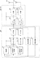
図1は、キャリアアグリゲーション(CA)及びデュアルコネクティビティ(DC)におけるセル構成の一例を示す図である。図1において、UEは、5つのセル(C1−C5)に接続している。C1はPCell(Primary Cell)であり、C2−C5はSCell(Secondary Cell)である場合を想定している。 FIG. 1 is a diagram illustrating an example of a cell configuration in carrier aggregation (CA) and dual connectivity (DC). In FIG. 1, the UE is connected to five cells (C1-C5). It is assumed that C1 is a PCell (Primary Cell) and C2-C5 is a SCell (Secondary Cell).
図1Aは、キャリアアグリゲーション(CA)に係る無線基地局及びユーザ端末の通信を示している。CAは、複数の周波数ブロック(コンポーネントキャリア(CC:Component Carrier)、セルとも呼ぶ)を統合して広帯域化する技術である。各CCは、例えば、最大20MHzの帯域幅を有し、最大5つのCCを統合する場合には最大100MHzの広帯域が実現される。 FIG. 1A shows communication between a radio base station and a user terminal according to carrier aggregation (CA). CA is a technology for integrating a plurality of frequency blocks (also referred to as component carrier (CC: Component Carrier), cell) to increase the bandwidth. Each CC has, for example, a maximum bandwidth of 20 MHz, and a maximum bandwidth of 100 MHz is realized when a maximum of five CCs are integrated.
図1Aに示す例において、無線基地局eNB1はマクロセルを形成する無線基地局(以下、マクロ基地局という)であり、無線基地局eNB2はスモールセルを形成する無線基地局(以下、スモール基地局という)とすることができる。例えば、スモール基地局は、マクロ基地局に接続するRRH(Remote Radio Head)のような構成であってもよい。このことから、CAは基地局内CA(intra-eNB CA)と呼ばれてもよい。 In the example shown in FIG. 1A, the radio base station eNB1 is a radio base station forming a macro cell (hereinafter referred to as a macro base station), and the radio base station eNB2 is a radio base station forming a small cell (hereinafter referred to as a small base station). ). For example, the small base station may be configured as an RRH (Remote Radio Head) connected to the macro base station. From this, CA may be called CA in a base station (intra-eNB CA).
キャリアアグリゲーションが適用される場合、1つのスケジューラ(例えば、マクロ基地局eNB1の有するスケジューラ)が複数セルのスケジューリングを制御する。マクロ基地局eNB1の有するスケジューラが複数セルのスケジューリングを制御する構成では、例えば、光ファイバのような高速回線などの理想的バックホール(ideal backhaul)で各無線基地局間が接続されることが想定される。また、CAでは、送信タイミングで分類されたタイミングアドバンスグループ(TAG:Timing Advance Group)をサポートしており、異なるTAGの最大送信タイミング差は32.47μsとなっている。 When carrier aggregation is applied, one scheduler (for example, a scheduler included in the macro base station eNB1) controls scheduling of a plurality of cells. In the configuration in which the scheduler of the macro base station eNB1 controls the scheduling of a plurality of cells, it is assumed that the radio base stations are connected by an ideal backhaul such as a high-speed line such as an optical fiber. Is done. CA supports timing advance groups (TAGs) classified by transmission timing, and the maximum transmission timing difference of different TAGs is 32.47 μs.
図1Bは、デュアルコネクティビティ(DC)に係る無線基地局及びユーザ端末の通信を示している。デュアルコネクティビティが適用される場合、複数のスケジューラが独立して設けられ、当該複数のスケジューラ(例えば、無線基地局MeNBの有するスケジューラ及び無線基地局SeNBの有するスケジューラ)がそれぞれ管轄する1つ以上のセルのスケジューリングを制御する。このことから、DCは基地局間CA(inter-eNB CA)と呼ばれてもよい。なお、DCにおいて、独立して設けられるスケジューラ(すなわち基地局)毎にCA(Intra-eNB CA)を適用してもよい。 FIG. 1B shows communication between a radio base station and a user terminal according to dual connectivity (DC). When dual connectivity is applied, a plurality of schedulers are provided independently, and one or more cells each managed by the plurality of schedulers (for example, a scheduler included in the radio base station MeNB and a scheduler included in the radio base station SeNB) Control the scheduling of From this, DC may be called CA between base stations (inter-eNB CA). In DC, CA (Intra-eNB CA) may be applied to each independently provided scheduler (ie, base station).
無線基地局MeNBの有するスケジューラ及び無線基地局SeNBの有するスケジューラがそれぞれの管轄する1つ以上のセルのスケジューリングを制御する構成では、例えば、X2インターフェースなどの遅延の無視できない非理想的バックホール(non-ideal backhaul)で各無線基地局間が接続されることが想定される。また、DCでは、無線基地局間が完全非同期で運用することも可能であり、異なる無線基地局の通信において最大500μsの送信タイミング差が生じる場合がある。 In the configuration in which the scheduler possessed by the radio base station MeNB and the scheduler possessed by the radio base station SeNB control the scheduling of one or more cells under their control, for example, a non-ideal backhaul (non-negligible non-negligible delay such as an X2 interface) -ideal backhaul), it is assumed that each radio base station is connected. Also, in DC, it is possible to operate between radio base stations completely asynchronously, and there may be a transmission timing difference of up to 500 μs in communication between different radio base stations.
図1Bに示すように、デュアルコネクティビティでは、各無線基地局が、1つ又は複数のセルから構成されるセルグループ(CG:Cell Group)を設定する。各セルグループは、同一無線基地局が形成する1つ以上のセル又は送信アンテナ装置、送信局などの同一送信ポイントが形成する1つ以上のセルから構成される。 As shown in FIG. 1B, in dual connectivity, each radio base station sets a cell group (CG: Cell Group) composed of one or a plurality of cells. Each cell group includes one or more cells formed by the same radio base station, or one or more cells formed by the same transmission point such as a transmission antenna device or a transmission station.
PCellを含むセルグループはマスタセルグループ(MCG:Master Cell Group)と呼ばれ、マスタセルグループ以外のセルグループはセカンダリセルグループ(SCG:Secondary Cell Group)と呼ばれる。MCG及びSCGを構成するセルの合計数は、所定値(例えば、5セル)以下となるように設定される。 A cell group including PCell is called a master cell group (MCG), and cell groups other than the master cell group are called secondary cell groups (SCG). The total number of cells constituting the MCG and SCG is set to be a predetermined value (for example, 5 cells) or less.
MCGが設定される(MCGを用いて通信する)無線基地局はマスタ基地局(MeNB:Master eNB)と呼ばれ、SCGが設定される(SCGを用いて通信する)無線基地局はセカンダリ基地局(SeNB:Secondary eNB)と呼ばれる。 A radio base station in which MCG is set (communication using MCG) is called a master base station (MeNB: Master eNB), and a radio base station in which SCG is set (communication using SCG) is a secondary base station. It is called (SeNB: Secondary eNB).
デュアルコネクティビティでは、無線基地局間はキャリアアグリゲーションと同等の協調は前提としない。そのため、ユーザ端末は、セルグループごとに下りリンクL1/L2制御(PDCCH/EPDCCH)、上りリンクL1/L2制御(PUCCH/PUSCHによるUCI(Uplink Control Information)フィードバック)を独立に行う事が可能となっている。したがってSeNBにおいても、PCellと同等の機能(例えば、共通サーチスペース、PUCCHなど)を有する特別なSCellが必要となる。PCellと同等の機能を有する特別なSCellのことを、「PSCell」ともいう。 In dual connectivity, cooperation equivalent to carrier aggregation is not assumed between radio base stations. Therefore, the user terminal can independently perform downlink L1 / L2 control (PDCCH / EPDCCH) and uplink L1 / L2 control (UCI (Uplink Control Information by PUCCH / PUSCH) feedback) for each cell group. ing. Therefore, also in SeNB, special SCell which has a function (for example, common search space, PUCCH, etc.) equivalent to PCell is required. A special SCell having a function equivalent to that of PCell is also referred to as “PSCell”.
ところで、LTE/LTE−Aシステムの上りリンク(UL)ではアンテナ選択を用いる送信ダイバーシチ法が規定されている。また、図1Aで示したキャリアアグリゲーション(CA)におけるアンテナ選択では、異なるセル(CC)で共通の送信アンテナを選択することが規定されている。つまり、ユーザ端末は、所定のUL信号(例えば、PUSCH、SRS等)を送信する場合に選択されるアンテナが、全てのセルで同一であると仮定して動作する。 By the way, a transmission diversity method using antenna selection is defined in the uplink (UL) of the LTE / LTE-A system. Further, in the antenna selection in the carrier aggregation (CA) shown in FIG. 1A, it is specified that a common transmission antenna is selected in different cells (CC). That is, the user terminal operates assuming that the antenna selected when transmitting a predetermined UL signal (for example, PUSCH, SRS, etc.) is the same in all cells.
例えば、ユーザ端末がCAを適用してCell#0とCell#1に接続する場合、Cell#0とCell#1におけるUL送信(例えば、PUSCH送信)において、同じアンテナポートを利用する。ユーザ端末がUL送信において2つのアンテナポート(Tx0とTx1)を適用する場合、Tx0又はTx1のいずれかを選択して複数のCCと通信を行う(図2A参照)。
For example, when a user terminal applies CA and connects to
このように、ユーザ端末が複数のセル(CC)と接続する場合に、異なるCCで共通のアンテナを用いることにより、単一のRFスイッチやRF回路(アンプ等)で通信を行うことができる。これにより、ユーザ端末の回路規模の増大を抑制することが可能となる(図2B参照)。なお、図2Bは、CAを適用するユーザ端末の構成の一例を示している。 Thus, when a user terminal is connected to a plurality of cells (CC), communication can be performed with a single RF switch or RF circuit (such as an amplifier) by using a common antenna in different CCs. Thereby, it becomes possible to suppress an increase in the circuit scale of the user terminal (see FIG. 2B). Note that FIG. 2B shows an example of the configuration of a user terminal to which CA is applied.
BB信号発生部(Baseband Signal Generator)21は、UL信号(上り制御信号、上りデータ信号、上り参照信号など)を生成する。データ信号には、チャネル状態などに基づいて決定された符号化率、変調方式などに従って符号化処理、変調処理が行われる。生成された信号は、サブキャリアマッピングやプリコーディングが適用され、IFFT部22に出力される。
The BB signal generator (Baseband Signal Generator) 21 generates a UL signal (uplink control signal, uplink data signal, uplink reference signal, etc.). The data signal is subjected to coding processing and modulation processing according to a coding rate, a modulation scheme, and the like determined based on a channel state and the like. Subcarrier mapping and precoding are applied to the generated signal and output to
IFFT部22は、BB信号発生部21から入力された周波数領域の信号に、逆高速フーリエ変換(IFFT:Inverse Fast Fourier Transform)を適用して時間領域の信号に変換し、RF部23に出力する。
The
RF部23は、IFFT部22から入力されたベースバンド信号を無線周波数帯に変換して、SW部24に出力する。例えば、RF部23は、所定の基準信号に基づいて、Cell#0やCell#1の周波数を生成して、ベースバンド信号を変換することができる。
The
SW部24は、無線基地局からのフィードバック情報に従って、RF部23から入力された信号を出力するアンテナ25(アンテナポート)を切り替える。当該フィードバック情報は、例えば、切り替えるアンテナを指定するためのアンテナ選択情報であってもよい。
The
なお、上記の例では信号送信時のアンテナ選択ダイバーシチを示しているが、これに限られない。 In the above example, antenna selection diversity at the time of signal transmission is shown, but the present invention is not limited to this.
一方で、Rel.12以降で導入されるデュアルコネクティビティ(DC)を適用する場合、アンテナスイッチングを用いる送信ダイバーシチ法をどのように制御するかが問題となる。例えば、DCを適用する場合もCAと同様にアンテナ選択を制御する(全てのCCで共通のアンテナを選択する)ことが考えられる。 On the other hand, Rel. In the case of applying dual connectivity (DC) introduced in 12 or later, there is a problem of how to control the transmission diversity method using antenna switching. For example, when DC is applied, it is conceivable to control antenna selection (select a common antenna for all CCs) in the same manner as CA.
しかし、デュアルコネクティビティ(DC)では、複数の無線基地局はそれぞれ独立してスケジューリングを制御する。また、複数の無線基地局が必ずしも同期しているとは限らず、非同期で運用する場合も想定される。非同期で運用される場合、ユーザ端末から異なる無線基地局に対するUL信号の送信タイミングが大きく異なる場合がある。 However, in dual connectivity (DC), a plurality of radio base stations independently control scheduling. In addition, a plurality of radio base stations are not necessarily synchronized, and it is also assumed that they operate asynchronously. When operated asynchronously, the transmission timing of the UL signal from the user terminal to different radio base stations may be greatly different.
したがって、閉ループアンテナ選択を適用するユーザ端末が、異なるCC間(特に、セルグループが異なるCC間)で同一の送信アンテナを選択するように制御することは困難となる。また、ユーザ端末が異なるCC間で同一の送信アンテナを選択する場合、選択方法によってはアンテナスイッチングを用いた送信ダイバーシチの効果が十分に得られず、通信品質が低下するおそれがある。 Therefore, it is difficult for a user terminal to which closed-loop antenna selection is applied to perform control so as to select the same transmission antenna between different CCs (particularly, between CCs having different cell groups). Also, when the user terminal selects the same transmission antenna between different CCs, the effect of transmission diversity using antenna switching may not be sufficiently obtained depending on the selection method, and communication quality may be degraded.
そこで、本発明者等は、デュアルコネクティビティ(DC)を適用して複数の無線基地局と接続する場合に、当該DCにおける通信動作を考慮してユーザ端末における送信アンテナ選択を適切に制御することを着想した。 Therefore, the present inventors appropriately control transmission antenna selection in the user terminal in consideration of communication operation in the DC when connecting to a plurality of radio base stations by applying dual connectivity (DC). Inspired.
以下に本実施の形態について、詳細に説明する。なお、以下の説明では、デュアルコネクティビティ(DC)を適用する場合に、所定のUL送信(PUSCH送信及び/又はSRS送信)におけるアンテナ選択(UE transmit antenna selection)を行う場合を想定するが、本実施の形態が適用可能なUL送信はこれらに限られず、例えばPUCCH、PRACH、DM−RS等のその他の上りチャネル・信号を含む。また、以下の説明では、ユーザ端末が2つのアンテナ(アンテナポート)の選択を制御する場合を示すが、アンテナポート数はこれに限られない。また、本実施の形態は、開ループアンテナ選択と閉ループアンテナ選択の双方に適用することができる。 This embodiment will be described in detail below. In the following description, it is assumed that antenna transmission (UE transmit antenna selection) is performed in predetermined UL transmission (PUSCH transmission and / or SRS transmission) when dual connectivity (DC) is applied. The UL transmission to which this form is applicable is not limited to these, and includes other uplink channels and signals such as PUCCH, PRACH, DM-RS, and the like. Moreover, although the following description shows a case where the user terminal controls selection of two antennas (antenna ports), the number of antenna ports is not limited to this. Further, the present embodiment can be applied to both open loop antenna selection and closed loop antenna selection.
(第1の態様)
第1の態様では、無線基地局(又は、セルグループ)毎にアンテナ選択を制御することにより、アンテナ選択ダイバーシチを適用する場合について説明する。つまり、第1の態様では、デュアルコネクティビティ(DC)を適用する場合にセルグループ単位でスケジューリング制御等を行うことに着目し、セルグループ単位でアンテナ選択の制御を行う。
(First aspect)
In the first aspect, a case will be described in which antenna selection diversity is applied by controlling antenna selection for each radio base station (or cell group). That is, in the first aspect, when dual connectivity (DC) is applied, focusing on performing scheduling control or the like in units of cell groups, antenna selection is controlled in units of cell groups.
図3に示すように、ユーザ端末が5つのセル(Cell#0−Cell#4)に接続する場合を想定する。図3では、無線基地局#1(eNB#1)がCell#0とCell#1を設定し、無線基地局#2(eNB#2)がCell#2−Cell#4を設定する場合を示している。
As shown in FIG. 3, the case where a user terminal connects to five cells (Cell # 0-Cell # 4) is assumed. FIG. 3 shows a case where the radio base station # 1 (eNB # 1) sets
また、ここでは、無線基地局#1がマスタ基地局(MeNB:Master eNB)であり、Cell#0とCell#1によりマスタセルグループ(MCG:Master Cell Group)が構成される場合(Cell#0又はCell#1がPCellの場合)を示している。また、無線基地局#2がセカンダリ基地局(SeNB:Secondary eNB)であり、Cell#2−Cell#4によりセカンダリセルグループ(SCG:Secondary Cell Group)が構成される場合(Cell#2−Cell#4のいずれかがPSCellの場合)を示している。もちろん本実施の形態が適用可能な構成はこれに限られない。
In addition, here, when the radio
第1の態様では、図3Aに示すように、無線基地局(又は、セルグループ)毎にユーザ端末におけるアンテナ選択を行う。つまり、アンテナ選択をセルグループ毎に制御する。 In the first mode, as shown in FIG. 3A, antenna selection is performed in the user terminal for each radio base station (or cell group). That is, antenna selection is controlled for each cell group.
例えば、マスタセルグループを構成するセル(Cell#0とCell#1)に対して共通のアンテナポート(図3AではTx0)を選択してUL送信を行うことができる。また、セカンダリセルグループを構成するセル(Cell#2−Cell#4)に対して共通のアンテナポート(図3AではTx1)を選択してUL送信を行うことができる。なお、ユーザ端末は、少なくともセルグループ毎に共通のアンテナを選択すればよく、セルグループ間で同一のアンテナを用いることも異なるアンテナを用いる事も可能である。さらに、本動作はセルグループ間が同期している場合でも非同期の場合でも適用が可能である。
For example, UL transmission can be performed by selecting a common antenna port (Tx0 in FIG. 3A) for cells (
このように、ユーザ端末においてセルグループ毎にアンテナ選択を制御して、アンテナ選択ダイバーシチを適用することにより、各セルグループでダイバーシチ利得を適切に実現して通信品質を向上することが可能となる。また、同一セルグループでは、共通のアンテナを選択することにより、ユーザ端末の回路構成の複雑化を抑制することができる。特に、無線基地局毎に周波数間CA(inter-band CA)を行う場合であっても、RF回路の増加を抑制することができる(図3B参照)。 Thus, by controlling antenna selection for each cell group and applying antenna selection diversity in the user terminal, it is possible to appropriately realize diversity gain in each cell group and improve communication quality. Moreover, in the same cell group, the complication of the circuit configuration of the user terminal can be suppressed by selecting a common antenna. In particular, even when inter-band CA is performed for each radio base station, an increase in the number of RF circuits can be suppressed (see FIG. 3B).
図3Aにおいて、開ループ送信アンテナ選択(open-loop UE transmit antenna selection)を適用する場合、例えば、ユーザ端末が無線基地局(セルグループ)毎に所定のアンテナポートを選択することができる。 In FIG. 3A, when applying open-loop UE transmit antenna selection, for example, a user terminal can select a predetermined antenna port for each radio base station (cell group).
閉ループ送信アンテナ選択(closed-loop UE transmit antenna selection)を適用する場合、各無線基地局がそれぞれ所定のアンテナポートを選択してユーザ端末にアンテナポートに関するアンテナ選択情報を通知する。ユーザ端末は通知されたアンテナ選択情報に基づいて、各セルグループのUL送信に適用するアンテナポートを選択することができる。 When applying closed-loop transmit antenna selection (closed-loop UE transmit antenna selection), each radio base station selects a predetermined antenna port and notifies the user terminal of antenna selection information related to the antenna port. The user terminal can select an antenna port to be applied to UL transmission of each cell group based on the notified antenna selection information.
例えば、閉ループ送信アンテナ選択において、ユーザ端末は、下り制御チャネル(PDCCH及び/又はEPDCCH)を介して送信される下り制御情報(DCI)に含まれる情報に基づいて所定のアンテナ(アンテナポート)を選択することができる。下り制御情報としては、ULグラント(例えば、DCIフォーマット0及び/又はDCIフォーマット4)を利用することができる。もちろんアンテナ選択情報を通知する方法はこれに限られない。
For example, in closed-loop transmission antenna selection, the user terminal selects a predetermined antenna (antenna port) based on information included in downlink control information (DCI) transmitted via the downlink control channel (PDCCH and / or EPDCCH). can do. As the downlink control information, UL grant (for example,
また、図3Aのようにユーザ端末に複数のセルグループが設定される場合、当該ユーザ端末は、各セルグループにおいて、それぞれ同じアンテナポート番号(transmit antenna port value)が通知されると仮定して動作することができる。例えば、図3Aにおいて、ユーザ端末は、所定サブフレームにおいて、マスタセルグループを構成するCell#0とCell#1からそれぞれ送信される下り制御信号には、同じアンテナポート番号(例えば、Tx0)を指示するアンテナ選択情報が含まれると想定することができる。
Also, when a plurality of cell groups are set in the user terminal as shown in FIG. 3A, the user terminal operates assuming that the same antenna port number (transmit antenna port value) is notified in each cell group. can do. For example, in FIG. 3A, the user terminal indicates the same antenna port number (for example, Tx0) in downlink control signals transmitted from
また、ユーザ端末に複数のセルグループが設定される場合、当該ユーザ端末は、各セルグループにおいて、異なるアンテナポートを用いたUL信号(例えば、SRS)の同時送信を行わないと仮定して動作することができる。例えば、図3Aにおいて、ユーザ端末は、マスタセルグループを構成するCell#0とCell#1から異なるアンテナポート(例えば、Cell#0がTx0、Cell#1がTx1)を用いたSRS送信を同時には行わないと想定することができる。
In addition, when a plurality of cell groups are set in the user terminal, the user terminal operates assuming that simultaneous transmission of UL signals (for example, SRS) using different antenna ports is not performed in each cell group. be able to. For example, in FIG. 3A, the user terminal simultaneously performs SRS transmission using different antenna ports (for example,
この場合、閉ループ制御における選択アンテナの通知はセルグループに属する一つのセルからのみ通知しシグナリングを簡易化しても良いし、全てのセルで同一アンテナを通知しシグナリングの仕様を一元化(簡易化)しても良いし、シグナリングが優先されるセルを規定することでシグナリング制御を簡単化しても良い。 In this case, the notification of the selected antenna in the closed loop control may be notified only from one cell belonging to the cell group to simplify the signaling, or the same antenna is notified in all cells and the signaling specification is unified (simplified). Alternatively, signaling control may be simplified by defining a cell in which signaling is prioritized.
このように、ユーザ端末は、同じセルグループを構成するセル(CC)に対して同一のアンテナポートを選択することにより、回路構成の簡易化を実現すると共にダイバーシチ利得を向上することが可能となる。 As described above, the user terminal can simplify the circuit configuration and improve the diversity gain by selecting the same antenna port for the cells (CC) configuring the same cell group. .
また、本実施の形態では、無線基地局(セルグループ)毎に送信アンテナ選択(UE transmit antenna selection)の設定を制御(enable/disable)する構成としてもよい。例えば、マスタセルグループ(Cell#0、Cell#1)に対してアンテナ選択を設定し(enable)、セカンダリセルグループ(Cell#2−#4)に対してアンテナ選択を非設定(disable)とすることができる。この場合、各無線基地局がそれぞれユーザ端末に対して、アンテナ選択ダイバーシチを適用するか否か制御してもよいし、PCellが制御してもよい。
Moreover, in this Embodiment, it is good also as a structure which controls (enable / disables) the setting of transmission antenna selection (UE transmit antenna selection) for every wireless base station (cell group). For example, antenna selection is set for the master cell group (
なお、図3Aでは、無線基地局(セルグループ)毎についてアンテナ選択を制御する場合を示したが本実施の形態はこれに限られない。他にも、タイミングアドバンスグループ(TAG)毎にアンテナ選択を適用してもよいし、周波数(バンド)毎にアンテナ選択を適用してもよい。また、セルグループ、タイミングアドバンスグループ、周波数(バンド)を組み合わせてアンテナ選択を適用することも可能である。 Although FIG. 3A shows a case where antenna selection is controlled for each radio base station (cell group), the present embodiment is not limited to this. In addition, antenna selection may be applied for each timing advance group (TAG), or antenna selection may be applied for each frequency (band). It is also possible to apply antenna selection by combining cell groups, timing advance groups, and frequencies (bands).
(第2の態様)
第2の態様では、デュアルコネクティビティ(DC)を適用する場合に、セル(CC)毎に異なる送信アンテナを選択可能とする場合について説明する。
(Second aspect)
In the second aspect, a case will be described where different transmit antennas can be selected for each cell (CC) when dual connectivity (DC) is applied.
例えば、図4に示すように、ユーザ端末がCell#0とCell#1を含むマスタセルグループ(無線基地局#1)と、Cell#2−Cell#4を含むセカンダリセルグループ(無線基地局#2)に接続する場合を想定する。
For example, as shown in FIG. 4, the user terminal includes a master cell group (radio base station # 1) including
第2の態様では、セル(CC)毎に異なる送信アンテナを選択する(図4参照)。つまり、UL送信のアンテナ選択として、セル(CC)単位で適用するアンテナポートを選択する。図4では、Cell#0、Cell#2、Cell#4に対するUL送信にアンテナポート0(Tx0)を選択し、Cell#1、Cell#3に対するUL送信にアンテナポート1(Tx1)を選択する場合を示している。
In the second mode, a different transmission antenna is selected for each cell (CC) (see FIG. 4). That is, as UL transmission antenna selection, an antenna port to be applied in units of cells (CC) is selected. In FIG. 4, when antenna port 0 (Tx0) is selected for UL transmission for
例えば、閉ループ送信アンテナ選択(closed-loop UE transmit antenna selection)を適用する場合、各無線基地局は、セル(CC)毎にそれぞれ所定のアンテナポートを選択してユーザ端末にアンテナ選択情報を通知する。例えば、各セルから送信される下り制御情報に各セルで選択するアンテナ選択情報を含めてユーザ端末に通知する。ユーザ端末は通知されたアンテナ選択情報に基づいて、各セルのUL送信に適用するアンテナポートを選択することができる。なお、送信アンテナの選択は、複数のセル間が同期した状態で行っても非同期の状態で行っても良い。 For example, when applying closed-loop UE transmit antenna selection, each radio base station selects a predetermined antenna port for each cell (CC) and notifies the user terminal of antenna selection information. . For example, the user equipment terminal is notified of the downlink control information transmitted from each cell including the antenna selection information selected in each cell. The user terminal can select an antenna port to be applied to UL transmission of each cell based on the notified antenna selection information. The selection of the transmission antenna may be performed in a state where a plurality of cells are synchronized or in an asynchronous state.
このようにセルグループをわたって、セル(CC)毎にアンテナ選択を制御してアンテナ選択ダイバーシチを適用することにより送信ダイバーシチを効果的に向上することが可能となる。特に、各セルが利用する周波数が異なる場合には、セル毎にアンテナ選択を制御することによりアンテナ選択ダイバーシチを柔軟に制御することが可能となる。 Thus, it is possible to effectively improve transmission diversity by controlling antenna selection for each cell (CC) and applying antenna selection diversity across cell groups. In particular, when the frequency used by each cell is different, antenna selection diversity can be flexibly controlled by controlling antenna selection for each cell.
(第3の態様)
第3の態様では、デュアルコネクティビティ(DC)を適用する場合に、アンテナ選択ダイバーシチの適用を制限する場合について説明する。
(Third aspect)
In the third aspect, a case will be described in which application of antenna selection diversity is limited when dual connectivity (DC) is applied.
第3の態様では、デュアルコネクティビティ(DC)を適用する場合、ユーザ端末及び/又は無線基地局は、UL送信におけるアンテナ選択を適用しないように動作する。この場合、ユーザ端末は所定のアンテナポートを用いてUL送信を行うことができる。例えば、DCが設定されたユーザ端末は、所定のアンテナポート(例えば、Tx0)を選択してUL送信を行うことができる。これにより、デュアルコネクティビティ(DC)を適用する場合に、ユーザ端末の動作を簡略化することが可能となる。 In the 3rd mode, when applying dual connectivity (DC), a user terminal and / or a radio base station operate so that antenna selection in UL transmission may not be applied. In this case, the user terminal can perform UL transmission using a predetermined antenna port. For example, a user terminal set with DC can select a predetermined antenna port (for example, Tx0) and perform UL transmission. Thereby, when applying dual connectivity (DC), it becomes possible to simplify operation | movement of a user terminal.
より具体的には、例えばDCが設定され、TM1が設定されたユーザ端末は、PUSCHとSRSはアンテナポート0で送信する、としてもよい。
More specifically, for example, a user terminal in which DC is set and TM1 is set may transmit PUSCH and SRS through
また、サービングセルに対するアンテナ選択を設定されているユーザ端末は、複数のセルグループが設定されないと仮定して動作することができる。つまり、DCが設定された段階で、アンテナ選択の適用を制限することができる。また、複数(例えば、2以上の)セルグループが設定されているユーザ端末は、異なるアンテナポートで同時にUL信号(例えば、SRS)の送信を行わないと仮定して動作することができる。 In addition, a user terminal configured to select an antenna for a serving cell can operate assuming that a plurality of cell groups are not configured. That is, application of antenna selection can be restricted at the stage where DC is set. In addition, user terminals in which a plurality of (for example, two or more) cell groups are set can operate on the assumption that UL signals (for example, SRS) are not transmitted simultaneously on different antenna ports.
あるいは、ユーザ端末は、デュアルコネクティビティ(DC)を適用する場合に、1つのセルグループ(例えば、MCG)を構成するセル(CC)に対してアンテナ選択を適用し、他のセル(例えば、SCG)を構成するセルに対してアンテナ選択を適用しない構成としてもよい。この場合、アンテナ選択を適用するセルグループを構成するCCに対して上記第1の態様で示したように同一のアンテナポートを選択するように制御してもよい。 Alternatively, when applying dual connectivity (DC), the user terminal applies antenna selection to cells (CC) constituting one cell group (for example, MCG) and other cells (for example, SCG). It is good also as a structure which does not apply antenna selection with respect to the cell which comprises. In this case, control may be performed so that the same antenna port is selected as shown in the first aspect for the CCs constituting the cell group to which antenna selection is applied.
(第4の態様)
第4の態様では、デュアルコネクティビティ(DC)を適用する場合に、所定ルールに従ってアンテナを選択する場合について説明する。
(Fourth aspect)
In a fourth aspect, a case will be described in which dual connectivity (DC) is applied and an antenna is selected according to a predetermined rule.
デュアルコネクティビティ(DC)を適用する場合に、ユーザ端末は、特定のセルグループで選択されるアンテナポートを他のセルグループに対しても利用するように制御することができる。例えば、ユーザ端末が接続する複数のセルグループの中で特定のセルグループ(例えば、MCG)で選択するアンテナポートを他のセルグループ(例えば、SCG)においても選択する(図5参照)。 When applying dual connectivity (DC), a user terminal can be controlled to use an antenna port selected in a specific cell group for other cell groups. For example, an antenna port selected in a specific cell group (for example, MCG) among a plurality of cell groups to which the user terminal is connected is also selected in another cell group (for example, SCG) (see FIG. 5).
図5では、ユーザ端末が、マスタセルグループ(Cell#0、Cell#1)において選択されるTx0を、セカンダリセルグループ(Cell#2−#4)のUL送信に適用する場合を示している。
In FIG. 5, the case where a user terminal applies Tx0 selected in a master cell group (
閉ループ送信アンテナ選択(closed-loop UE transmit antenna selection)を適用する場合、各セルグループにおいて無線基地局からユーザ端末にアンテナポート情報が通知される。そのため、図5では、セカンダリセルグループにおいて無線基地局からユーザ端末にアンテナポート情報が通知される場合には、ユーザ端末は通知されたアンテナポート情報は無視し、マスタセルグループで選択されるアンテナポートを利用して、セカンダリセルグループにおけるUL送信を制御する。 When applying closed-loop UE transmit antenna selection, antenna port information is notified from the radio base station to the user terminal in each cell group. Therefore, in FIG. 5, when the antenna port information is notified from the radio base station to the user terminal in the secondary cell group, the user terminal ignores the notified antenna port information, and the antenna port selected in the master cell group Is used to control UL transmission in the secondary cell group.
この場合、複数のセルグループが設定されるユーザ端末は、マクロセルグループを構成するセルで通知されるアンテナポート番号が、各セルで送信される下り制御情報(例えば、DCIフォーマット0)に含まれると想定して動作することができる。また、複数のセルグループが設定されるユーザ端末は、マクロセルグループを構成するセルのSRS送信で利用したアンテナポートを選択して、他セルのSRSの送信を制御することができる。 In this case, for a user terminal in which a plurality of cell groups are set, the antenna port number notified in the cells constituting the macro cell group is included in downlink control information (for example, DCI format 0) transmitted in each cell. It can operate assuming. Moreover, the user terminal in which a some cell group is set can select the antenna port utilized by SRS transmission of the cell which comprises a macrocell group, and can control transmission of SRS of another cell.
なお、図5に示す場合、他のセルグループ(SCG)からユーザ端末に対してアンテナポートに関するアンテナ選択情報を通知しない構成としてもよい。この場合、ユーザ端末は所定のセルグループ(例えば、MCG)で送信されるアンテナ選択情報に基づいて、アンテナ選択を制御することができる。 In addition, in the case shown in FIG. 5, it is good also as a structure which does not notify the antenna selection information regarding an antenna port with respect to a user terminal from another cell group (SCG). In this case, the user terminal can control antenna selection based on antenna selection information transmitted in a predetermined cell group (for example, MCG).
同様に、図5に示す場合、アンテナ選択情報の通知は単一のセル(CC)から行い、当該セル以外からユーザ端末に対してアンテナポートに関するアンテナ選択情報を通知しない構成としてもよい。この場合、ユーザ端末は所定のセル(例えば、Cell#0)で送信されるアンテナ選択情報に基づいて、アンテナ選択を制御することができる。 Similarly, in the case illustrated in FIG. 5, the antenna selection information may be notified from a single cell (CC), and the antenna selection information related to the antenna port may not be notified from other cells to the user terminal. In this case, the user terminal can control antenna selection based on antenna selection information transmitted in a predetermined cell (for example, Cell # 0).
このように、特定のセルグループで選択されるアンテナポートを他のセルグループに対しても適用することにより、ユーザ端末におけるアンテナ選択動作を簡略化すると共に、送信ダイバーシチ利得を実現することができる。 In this way, by applying the antenna port selected in a specific cell group to other cell groups, it is possible to simplify the antenna selection operation in the user terminal and to realize transmission diversity gain.
あるいは、デュアルコネクティビティ(DC)を適用する場合に、ユーザ端末は、他の物理チャネルの送信で利用するアンテナポートを選択することができる。例えば、上記図3Aに示す構成において、Cell#0においてPUCCHが送信され、Cell#1においてPUSCHが送信される場合を想定する。
Or when applying dual connectivity (DC), the user terminal can select the antenna port used by transmission of another physical channel. For example, in the configuration shown in FIG. 3A, it is assumed that PUCCH is transmitted in
この場合、ユーザ端末は、Cell#1のPUSCH送信のアンテナポートとして、Cell#0のPUCCH送信に用いるアンテナポート(例えば、Tx0)を選択することができる。つまり、PUSCHやSRSの送信に利用するアンテナを他の物理チャネル(例えば、PUCCH)の送信アンテナと関連付けて制御する。なお、他の物理チャネルとしては、同一セルグループのセルで送信される物理チャネルとしてもよいし、他のセルグループのセルで送信される物理チャネルとしてもよい。
In this case, the user terminal can select an antenna port (for example, Tx0) used for PUCCH transmission of
このように、特定の物理チャネル(例えば、PUCCH)に利用するアンテナポートに基づいてアンテナ選択ダイバーシチを適用することにより、ユーザ端末におけるアンテナ選択動作を簡略化すると共に、送信ダイバーシチ利得を実現することができる。 In this way, by applying antenna selection diversity based on the antenna port used for a specific physical channel (for example, PUCCH), it is possible to simplify the antenna selection operation in the user terminal and realize transmission diversity gain. it can.
あるいは、デュアルコネクティビティ(DC)を適用する場合に、ユーザ端末は、あらかじめ規定された数式に基づいて送信アンテナの切替えを行っても良い。特にSRSの送信アンテナの切替えにおいては閉ループ型制御によるダイバーシチ利得を主な目的としていない為、あらかじめ切替え方法を規定する事により基地局における制御およびシグナリングを簡素化する事が可能である。当該式は例えばセルID(例えばPCell、PSCell、各セルのセルID)、サブフレーム番号、スロット番号を基に構成されていても良い。 Alternatively, when applying dual connectivity (DC), the user terminal may switch the transmission antenna based on a predetermined mathematical formula. In particular, since the diversity gain by the closed loop control is not the main purpose in switching the transmission antenna of the SRS, it is possible to simplify the control and signaling in the base station by defining the switching method in advance. The said formula may be comprised based on cell ID (for example, PCell, PSCell, cell ID of each cell), a sub-frame number, and a slot number, for example.
上記に示す数式は例えばRel.8 LTEで規定されている上りSRSアンテナスイッチングの関数を流用しても良い。また、上記に示す数式に基づいた切替え法は、セル毎に行っても、セルグループ毎に行っても、全セル共通で行っても良い。加えて、同期セル、非同期セルの分類に因らず適用できる。 The mathematical formula shown above is, for example, Rel. A function of uplink SRS antenna switching defined in 8 LTE may be used. Moreover, the switching method based on the mathematical formula shown above may be performed for each cell, for each cell group, or for all cells. In addition, it can be applied regardless of the classification of synchronous cells and asynchronous cells.
(変形例)
なお、デュアルコネクティビティ(DC)を適用する場合に、ユーザ端末側でアンテナ選択を適宜制御する構成としてもよい。つまり、ユーザ端末側にアンテナ選択の自由度を持たせることにより、ユーザ端末毎に柔軟にアンテナポートを選択してUL送信を行うことが可能となる。特に、開ループ送信アンテナ選択(open-loop UE transmit antenna selection)を適用する場合、ユーザ端末側でアンテナポートを適宜選択する構成とすることが好ましい。
(Modification)
In addition, when applying dual connectivity (DC), it is good also as a structure which controls antenna selection suitably on the user terminal side. That is, by providing the user terminal side with a degree of freedom of antenna selection, it is possible to flexibly select an antenna port for each user terminal and perform UL transmission. In particular, when applying open-loop UE transmit antenna selection, it is preferable that the user terminal side appropriately select an antenna port.
上記技術に関して、上りリンクの異なる物理チャネル・信号で異なる方法を用いても良い。例えば閉ループ型制御を行うPUSCHのアンテナスイッチングと開ループ型制御を行うSRSのアンテナスイッチングに適用する方法は別々であっても良い。 With regard to the above technique, different methods may be used for different physical channels / signals in the uplink. For example, the method applied to PUSCH antenna switching for performing closed-loop control and SRS antenna switching for performing open-loop control may be different.
また、上記説明では、閉ループ送信アンテナ選択(closed-loop UE transmit antenna selection)を適用する場合、無線基地局からユーザ端末に対して下り制御情報(例えば、DCIフォーマット0)を用いてアンテナ選択情報を動的(ダイナミック)に通知する場合を示したが、本実施の形態はこれに限られない。他にも、上位レイヤシグナリング(RRCシグナリング、報知情報等)を用いて、アンテナ選択情報をユーザ端末に準静的(セミスタティック)通知することも可能である。 Also, in the above description, when applying closed-loop UE transmit antenna selection, antenna selection information is transmitted from the radio base station to the user terminal using downlink control information (for example, DCI format 0). Although the case of notifying dynamically (dynamic) has been shown, the present embodiment is not limited to this. In addition, it is also possible to notify the antenna selection information to the user terminal quasi-static (semi-static) using higher layer signaling (RRC signaling, broadcast information, etc.).
例えば、マスタ基地局内(intra-MeNB)でハンドオーバを適用する場合(intra-MeNB HO)、ハンドオーバに伴いRRC再設定を行う場合が生じる。この場合、ユーザ端末が各無線基地局(セルグループ)に対するUL送信用のアンテナを再選択する。そのため、ハンドオーバを行う際にRRCシグナリングを用いて各セルグループ(無線基地局)で適用するアンテナ選択情報をユーザ端末に通知することにより、アンテナ選択を適切に制御することができる。 For example, when handover is applied within the master base station (intra-MeNB) (intra-MeNB HO), RRC reconfiguration may be performed along with the handover. In this case, the user terminal reselects the UL transmission antenna for each radio base station (cell group). Therefore, antenna selection can be appropriately controlled by notifying the user terminal of antenna selection information to be applied in each cell group (radio base station) using RRC signaling when performing handover.
また、デュアルコネクティビティ(DC)を適用する場合に、各無線基地局(セルグループ)間でアンテナ選択に関連する情報を共有してもよい。例えば、マスタ基地局とセカンダリ基地局間でバックホールリンク(例えば、X2インターフェース)を介して、それぞれのセルグループ(又はセル)で適用するアンテナに関する情報をやり取りすることができる。これにより、各無線基地局は、他の無線基地局(セルグループ)で利用されるアンテナに関する情報に基づいて、ユーザ端末に通知するアンテナポートを選択することができる。 In addition, when dual connectivity (DC) is applied, information related to antenna selection may be shared between radio base stations (cell groups). For example, information regarding the antenna applied in each cell group (or cell) can be exchanged between the master base station and the secondary base station via a backhaul link (for example, X2 interface). Thereby, each radio base station can select an antenna port to be notified to the user terminal based on information on the antennas used in other radio base stations (cell groups).
同様に、デュアルコネクティビティ(DC)を適用する場合に、各無線基地局(セルグループ)間で共有されている情報を基に切替え方法を決定してもよい。例えば、マスタ基地局とセカンダリ基地局間で共有しているCell IDに基づいて切替えを行っても良い。 Similarly, when applying dual connectivity (DC), the switching method may be determined based on information shared between the radio base stations (cell groups). For example, the switching may be performed based on the Cell ID shared between the master base station and the secondary base station.
(無線通信システムの構成)
以下、本発明の一実施の形態に係る無線通信システムの構成について説明する。この無線通信システムでは、上記第1の態様〜第4の態様、変形例のいずれか又はこれらの組み合わせが適用される。
(Configuration of wireless communication system)
Hereinafter, a configuration of a wireless communication system according to an embodiment of the present invention will be described. In this wireless communication system, any one of the first to fourth aspects and the modified examples or a combination thereof is applied.
図6は、本実施の形態に係る無線通信システムの概略構成図である。なお、図6に示す無線通信システムは、例えば、LTEシステム或いは、SUPER 3Gが包含されるシステムである。この無線通信システムでは、ユーザ端末がそれぞれスケジューラを有する複数の無線基地局と接続するデュアルコネクティビティ(DC)を適用することができる。また、各無線基地局は、少なくとも一つのセルから構成されるセルグループを設定することができる。また、この無線通信システムは、IMT−Advancedと呼ばれても良いし、4G、FRA(Future Radio Access)、5Gと呼ばれても良い。 FIG. 6 is a schematic configuration diagram of the radio communication system according to the present embodiment. Note that the radio communication system shown in FIG. 6 is a system including, for example, an LTE system or SUPER 3G. In this radio communication system, it is possible to apply dual connectivity (DC) in which each user terminal is connected to a plurality of radio base stations each having a scheduler. Each radio base station can set a cell group composed of at least one cell. Further, this radio communication system may be called IMT-Advanced, or may be called 4G, FRA (Future Radio Access), or 5G.
図6に示すように、無線通信システム1は、複数の無線基地局10(11及び12)と、各無線基地局10によって形成されるセル内にあり、各無線基地局10と通信可能に構成された複数のユーザ端末20と、を備えている。無線基地局10は、それぞれ上位局装置30に接続され、上位局装置30を介してコアネットワーク40に接続される。
As shown in FIG. 6, the
図6において、無線基地局11は、例えば相対的に広いカバレッジを有するマクロ基地局で構成され、マクロセルC1を形成する。無線基地局12は、局所的なカバレッジを有するスモール基地局で構成され、スモールセルC2を形成する。なお、無線基地局11及び12の数は、図6に示す数に限られない。
In FIG. 6, the
マクロセルC1及びスモールセルC2では、同一の周波数帯が用いられてもよいし、異なる周波数帯が用いられてもよい。また、無線基地局11及び12は、基地局間インターフェース(例えば、光ファイバ、X2インターフェース)を介して互いに接続される。
In the macro cell C1 and the small cell C2, the same frequency band may be used, or different frequency bands may be used. The
なお、無線基地局11(マクロ基地局)は、無線基地局、eNodeB(eNB)、送信ポイント(transmission point)などと呼ばれてもよい。無線基地局12(スモール基地局)は、ピコ基地局、フェムト基地局、Home eNodeB(HeNB)、送信ポイント、RRH(Remote Radio Head)などと呼ばれてもよい。以下、無線基地局11及び12を区別しない場合は、無線基地局10と総称する。
Note that the radio base station 11 (macro base station) may be referred to as a radio base station, an eNodeB (eNB), a transmission point, or the like. The radio base station 12 (small base station) may be referred to as a pico base station, a femto base station, a Home eNodeB (HeNB), a transmission point, an RRH (Remote Radio Head), or the like. Hereinafter, when the
上位局装置30には、例えば、アクセスゲートウェイ装置、無線ネットワークコントローラ(RNC)、モビリティマネジメントエンティティ(MME)などが含まれるが、これに限定されるものではない。
The
ユーザ端末20は、LTE、LTE−Aなどの各種通信方式に対応した端末であり、移動通信端末だけでなく固定通信端末を含んでいてもよい。また、ユーザ端末20は、上りリンク送信において、アンテナスイッチングを用いる送信ダイバーシチを適用することができる。例えば、UL送信(例えば、PUSCH及び/又はSRS送信)を行う際に、閉ループ送信アンテナ選択(closed-loop UE transmit antenna selection)及び/又は開ループ送信アンテナ選択(open-loop UE transmit antenna selection)を適用することができる。
The
閉ループ送信アンテナ選択では、ユーザ端末は、無線基地局から指示されるアンテナ選択情報(例えば、所定のアンテナポートに関する情報)を用いて所定のアンテナポート(例えば、1つのアンテナポート)を選択することができる。一方、開ループ送信アンテナ選択では、ユーザ端末側で適宜所定のアンテナポート(例えば、1つのアンテナポート)を選択することができる。ユーザ端末におけるアンテナ選択の制御方法は、上記第1の態様〜第4の態様、変形例のいずれか又はこれらの組み合わせを用いることができる。 In closed-loop transmission antenna selection, a user terminal can select a predetermined antenna port (for example, one antenna port) using antenna selection information (for example, information on a predetermined antenna port) instructed from a radio base station. it can. On the other hand, in the open loop transmission antenna selection, a predetermined antenna port (for example, one antenna port) can be appropriately selected on the user terminal side. As a method for controlling antenna selection in the user terminal, any one of the first to fourth aspects, the modified examples, or a combination thereof can be used.
無線通信システムにおいては、無線アクセス方式として、下りリンクについてはOFDMA(直交周波数分割多元接続)を適用し、上りリンクについてはSC−FDMA(シングルキャリア−周波数分割多元接続)を適用することができる。OFDMAは、周波数帯域を複数の狭い周波数帯域(サブキャリア)に分割し、各サブキャリアにデータをマッピングして通信を行うマルチキャリア伝送方式である。SC−FDMAは、システム帯域幅を端末毎に1つ又は連続したリソースブロックからなる帯域に分割し、複数の端末が互いに異なる帯域を用いることで、端末間の干渉を低減するシングルキャリア伝送方式である。なお、上り及び下りの無線アクセス方式は、これらの組み合わせに限られない。 In a radio communication system, OFDMA (orthogonal frequency division multiple access) can be applied to the downlink and SC-FDMA (single carrier-frequency division multiple access) can be applied to the uplink as radio access schemes. OFDMA is a multi-carrier transmission scheme that performs communication by dividing a frequency band into a plurality of narrow frequency bands (subcarriers) and mapping data to each subcarrier. SC-FDMA is a single-carrier transmission scheme that reduces interference between terminals by dividing the system bandwidth into bands composed of one or continuous resource blocks for each terminal, and a plurality of terminals using different bands. is there. The uplink and downlink radio access methods are not limited to these combinations.
無線通信システム1では、下りリンクのチャネルとして、各ユーザ端末20で共有される下り共有チャネル(PDSCH:Physical Downlink Shared Channel)、報知チャネル(PBCH:Physical Broadcast Channel)、下りL1/L2制御チャネル等が用いられる。PDSCHにより、ユーザデータや上位レイヤ制御情報、所定のSIB(System Information Block)が伝送される。また、PBCHにより、同期信号や、MIB(Master Information Block)などが伝送される。
In the
下りL1/L2制御チャネルは、PDCCH(Physical Downlink Control Channel)、EPDCCH(Enhanced Physical Downlink Control Channel)、PCFICH(Physical Control Format Indicator Channel)、PHICH(Physical Hybrid-ARQ Indicator Channel)等を含む。PDCCHにより、PDSCH及びPUSCHのスケジューリング情報を含む下り制御情報(DCI:Downlink Control Information)等が伝送される。PCFICHにより、PDCCHに用いるOFDMシンボル数が伝送される。PHICHにより、PUSCHに対するHARQの送達確認信号(ACK/NACK)が伝送される。EPDCCHは、PDSCH(下り共有データチャネル)と周波数分割多重され、PDCCHと同様にDCIなどを伝送するために用いられてもよい。 Downlink L1 / L2 control channels include PDCCH (Physical Downlink Control Channel), EPDCCH (Enhanced Physical Downlink Control Channel), PCFICH (Physical Control Format Indicator Channel), PHICH (Physical Hybrid-ARQ Indicator Channel), and the like. Downlink control information (DCI: Downlink Control Information) including PDSCH and PUSCH scheduling information is transmitted by the PDCCH. The number of OFDM symbols used for PDCCH is transmitted by PCFICH. The HAICH transmission confirmation signal (ACK / NACK) for PUSCH is transmitted by PHICH. The EPDCCH is frequency division multiplexed with a PDSCH (downlink shared data channel) and may be used to transmit DCI or the like in the same manner as the PDCCH.
無線通信システム1では、上りリンクのチャネルとして、各ユーザ端末20で共有される上り共有チャネル(PUSCH:Physical Uplink Shared Channel)、上り制御チャネル(PUCCH:Physical Uplink Control Channel)、ランダムアクセスチャネル(PRACH:Physical Random Access Channel)等が用いられる。PUSCHにより、ユーザデータや上位レイヤ制御情報が伝送される。また、PUCCHにより、下りリンクの無線品質情報(CQI:Channel Quality Indicator)、送達確認信号(HARQ-ACK)等が伝送される。PRACHにより、セルとの接続確立のためのランダムアクセスプリアンブル(RAプリアンブル)が伝送される。また、上りリンクの参照信号として、チャネル品質測定用の参照信号(SRS:Sounding Reference Signal)、PUCCHやPUSCHを復調するための復調用参照信号(DM−RS:Demodulation Reference Signal)等が送信される。
In the
図7は、本実施の形態に係る無線基地局10の全体構成図である。無線基地局10(無線基地局11及び12を含む)は、複数の送受信アンテナ101(アンテナポート)と、アンプ部102と、送受信部103と、ベースバンド信号処理部104と、呼処理部105と、伝送路インターフェース106とを備えている。なお、送受信部103は、送信部及び受信部から構成される。
FIG. 7 is an overall configuration diagram of the
下りリンクにより無線基地局10からユーザ端末20に送信されるユーザデータ(DLデータ)は、上位局装置30から伝送路インターフェース106を介してベースバンド信号処理部104に入力される。
User data (DL data) transmitted from the
ベースバンド信号処理部104では、ユーザデータに関して、PDCP(Packet Data Convergence Protocol)レイヤの処理、ユーザデータの分割・結合、RLC(Radio Link Control)再送制御などのRLCレイヤの送信処理、MAC(Medium Access Control)再送制御(例えば、HARQ(Hybrid Automatic Repeat reQuest)の送信処理)、スケジューリング、伝送フォーマット選択、チャネル符号化、逆高速フーリエ変換(IFFT:Inverse Fast Fourier Transform)処理、プリコーディング処理等の送信処理が行われて各送受信部103に転送される。また、下り制御信号に関しても、チャネル符号化や逆高速フーリエ変換などの送信処理が行われて、各送受信部103に転送される。
The baseband
各送受信部103は、ベースバンド信号処理部104からアンテナ毎にプリコーディングして出力された下り信号を無線周波数帯に変換して送信する。送受信部103で周波数変換された無線周波数信号は、アンプ部102により増幅され、送受信アンテナ101から送信される。送受信部103は、本発明に係る技術分野で利用されるトランスミッター/レシーバー、送受信回路又は送受信装置を適用することができる。
Each transmitting / receiving
一方、上り信号については、各送受信アンテナ101で受信された無線周波数信号がそれぞれアンプ部102で増幅される。各送受信部103はアンプ部102で増幅された上り信号を受信する。送受信部103は、受信信号をベースバンド信号に周波数変換して、ベースバンド信号処理部104に出力する。
On the other hand, for the uplink signal, the radio frequency signal received by each transmission /
ベースバンド信号処理部104では、入力された上り信号に含まれるユーザデータに対して、高速フーリエ変換(FFT:Fast Fourier Transform)処理、逆離散フーリエ変換(IDFT:Inverse Discrete Fourier Transform)処理、誤り訂正復号、MAC再送制御の受信処理、RLCレイヤ、PDCPレイヤの受信処理がなされ、伝送路インターフェース106を介して上位局装置30に転送される。呼処理部105は、通信チャネルの設定や解放などの呼処理や、無線基地局10の状態管理や、無線リソースの管理を行う。
The baseband
伝送路インターフェース106は、所定のインターフェースを介して、上位局装置30と信号を送受信する。また、伝送路インターフェース106は、基地局間インターフェース(例えば、光ファイバ、X2インターフェース)を介して隣接無線基地局と信号を送受信(バックホールシグナリング)してもよい。
The transmission path interface 106 transmits and receives signals to and from the
図8は、本実施の形態に係る無線基地局10が有するベースバンド信号処理部104の主な機能構成図である。なお、図8では、本実施の形態における特徴部分の機能ブロックを主に示しており、無線基地局10は、無線通信に必要な他の機能ブロックも有しているものとする。
FIG. 8 is a main functional configuration diagram of the baseband
図8に示すように、無線基地局10は、制御部(スケジューラ)301と、送信信号生成部302と、マッピング部303と、受信処理部304と、を少なくとも含んで構成されている。
As illustrated in FIG. 8, the
制御部(スケジューラ)301は、PDSCHで送信される下りデータ信号、PDCCH及び/又は拡張PDCCH(EPDCCH)で伝送される下り制御信号のスケジューリングを制御する。また、システム情報、同期信号、CRS、CSI−RSなどの下り参照信号などのスケジューリングの制御も行う。また、上り参照信号、PUSCHで送信される上りデータ信号、PUCCH及び/又はPUSCHで送信される上り制御信号等のスケジューリングを制御する。なお、制御部301は、本発明に係る技術分野で用いられるコントローラ、制御回路又は制御装置で構成することができる。
The control unit (scheduler) 301 controls scheduling of downlink data signals transmitted on PDSCH, downlink control signals transmitted on PDCCH and / or enhanced PDCCH (EPDCCH). In addition, scheduling control such as system information, synchronization signals, downlink reference signals such as CRS and CSI-RS is also performed. Further, scheduling of uplink reference signals, uplink data signals transmitted on PUSCH, uplink control signals transmitted on PUCCH and / or PUSCH, and the like is controlled. The
また、制御部301は、ユーザ端末20に対して送信アンテナ選択(UE transmit antenna selection)が設定されている場合に、ユーザ端末がUL送信(例えば、PUSCH及び/又はSRS送信)を行うアンテナポートの指示を制御することができる。具体的には、閉ループ送信アンテナ選択(closed-loop UE transmit antenna selection)を適用する場合に、制御部301は、ユーザ端末20が利用するアンテナポートを選択し、送信信号生成部302に出力する。アンテナ選択の制御方法は、上記第1の態様〜第4の態様、変形例のいずれか又はこれらの組み合わせを用いることができる。
In addition, when the transmission antenna selection (UE transmit antenna selection) is set for the
送信信号生成部302は、制御部301からの指示に基づいて、DL信号(下り制御信号、下りデータ信号、下り参照信号など)を生成して、マッピング部303に出力する。例えば、送信信号生成部302は、制御部301からの指示に基づいて、下り信号の割り当て情報を通知するDLアサインメント及び上り信号の割り当て情報を通知するULグラントを生成する。また、下りデータ信号には、各ユーザ端末20からのCSIなどに基づいて決定された符号化率、変調方式などに従って符号化処理、変調処理が行われる。
The transmission
また、送信信号生成部302は、制御部301からの指示に基づいて、送信アンテナ選択ダイバーシチを適用するユーザ端末20が選択するアンテナポートに関する情報(アンテナ選択情報)を生成する。例えば、下り制御情報(DCI)の所定フォーマット(例えば、DCIフォーマット0、4等)にアンテナ選択情報を含める。なお、送信信号生成部302は、本発明に係る技術分野で利用される信号生成器又は信号生成回路で構成することができる。
Also, the transmission
マッピング部303は、制御部301からの指示に基づいて、送信信号生成部302で生成された下り信号を無線リソースにマッピングして、送受信部103に出力する。マッピング部303は、本発明に係る技術分野で利用されるマッピング回路又はマッパーで構成することができる。
Based on an instruction from the
受信処理部304は、ユーザ端末20から送信されるUL信号(上り制御信号、上りデータ信号、上り参照信号など)に対して受信処理(例えば、デマッピング、復調、復号など)を行う。また、受信処理部304は、受信した信号を用いて受信電力(RSRP)やチャネル状態について測定してもよい。なお、処理結果や測定結果は、制御部301に出力されてもよい。受信処理部304は、本発明に係る技術分野で利用される信号処理器又は信号処理回路で構成することができる。
The
図9は、本実施の形態に係るユーザ端末20の全体構成図である。図9に示すように、ユーザ端末20は、複数の送受信アンテナ201(アンテナポート)と、アンプ部202と、送受信部203と、ベースバンド信号処理部204と、アプリケーション部205と、を備えている。なお、送受信部203は、送信部及び受信部から構成されてもよい。
FIG. 9 is an overall configuration diagram of the
複数の送受信アンテナ201で受信された無線周波数信号は、それぞれアンプ部202で増幅される。各送受信部203はアンプ部202で増幅された下り信号を受信する。送受信部203は、受信信号をベースバンド信号に周波数変換して、ベースバンド信号処理部204に出力する。送受信部203は、本発明に係る技術分野で利用されるトランスミッター/レシーバー、送受信回路又は送受信装置で構成することができる。
Radio frequency signals received by the plurality of transmission /
ベースバンド信号処理部204は、入力されたベースバンド信号に対して、FFT処理や、誤り訂正復号、再送制御の受信処理などを行う。下りリンクのユーザデータは、アプリケーション部205に転送される。アプリケーション部205は、物理レイヤやMACレイヤより上位のレイヤに関する処理などを行う。また、下りリンクのデータのうち、報知情報もアプリケーション部205に転送される。
The baseband
一方、上りリンクのユーザデータについては、アプリケーション部205からベースバンド信号処理部204に入力される。ベースバンド信号処理部204では、再送制御の送信処理(例えば、HARQの送信処理)や、チャネル符号化、プリコーディング、離散フーリエ変換(DFT:Discrete Fourier Transform)処理、IFFT処理などが行われて各送受信部203に転送される。送受信部203は、ベースバンド信号処理部204から出力されたベースバンド信号を無線周波数帯に変換して送信する。送受信部203で周波数変換された無線周波数信号は、アンプ部202により増幅され、送受信アンテナ201から送信される。
On the other hand, uplink user data is input from the
送受信部203は、1つ以上のセルから構成されるセルグループ(CG)をそれぞれ設定する複数の無線基地局との間で信号を送受信することができる。例えば、送受信部203は、ユーザ端末20が送信アンテナ選択(UE transmit antenna selection)を行う場合に、所定のアンテナポートを選択して、UL信号(例えば、PUSCH、SRS等)の送信を行うことができる。
The transmission /
図10は、ユーザ端末20が有するベースバンド信号処理部204、送受信部203、アンプ部202の主な機能構成図である。なお、図10においては、本実施の形態における特徴部分の機能ブロックを主に示しており、ユーザ端末20は、無線通信に必要な他の機能ブロックも有しているものとする。
FIG. 10 is a main functional configuration diagram of the baseband
図10に示すように、ユーザ端末20は、制御部401と、送信信号生成部402と、マッピング部403と、IFFT部404と、RF/アンプ部405と、SW部406と、受信処理部407と、を少なくとも含んで構成されている。ここではRF回路にアンプ回路を含めた場合を示している。
As illustrated in FIG. 10, the
制御部401は、無線基地局10から送信された下り制御信号(PDCCH/EPDCCHで送信された信号)及び下りデータ信号(PDSCHで送信された信号)を、受信処理部407から取得する。制御部401は、下り制御信号や、下りデータ信号に対する再送制御の要否を判定した結果などに基づいて、UL信号の生成を制御する。具体的には、制御部401は、送信信号生成部402、マッピング部403及びSW部406の制御を行う。なお、制御部401は、本発明に係る技術分野で利用されるコントローラ、制御回路又は制御装置で構成することができる。
The
また、制御部401は、ユーザ端末20が送信アンテナ選択(UE transmit antenna selection)を行う場合に、所定のアンテナポートの選択し、選択したアンテナポートを用いるようにSW部406を制御する。例えば、ユーザ端末20が複数の無線基地局(セルグループ)と接続する場合、制御部401は、同じセルグループを構成するセルに対して同一の送信アンテナポートを選択することができる(上記第1の態様)。
In addition, when the
また、閉ループ送信アンテナ選択(closed-loop UE transmit antenna selection)を適用する場合、制御部401は、無線基地局から通知されるアンテナ選択情報に基づいて、各セルグループを構成するセルで利用する利用する送信アンテナポートを選択することができる。
Also, when applying closed-loop UE transmit antenna selection, the
この際、制御部401は、同一セルグループを構成する各セルで送信されるアンテナ選択情報が同一であると想定してもよい。また、制御部401は、UL信号としてSRSを送信する場合、各セルグループにおいて同時に異なる送信アンテナポートを用いた送信は行わないように制御することができる。
At this time, the
あるいは、制御部401は、セルごとに異なる送信アンテナを選択することができる(上記第2の態様)。あるいは、制御部401は、デュアルコネクティビティでは、アンテナ選択を適用しないように制御してもよい(上記第3の態様)。
Or the
あるいは、制御部401は、特定のセルグループ(例えば、MCG)で選択した送信アンテナポートと同一の送信アンテナポートを他のセルグループ(例えば、SCG)のUL送信に対して選択することができる(上記第4の態様)。
Or the
送信信号生成部402(ベースバンド信号生成部)は、制御部401からの指示に基づいて、UL信号を生成して、マッピング部403に出力する。例えば、送信信号生成部402は、制御部401からの指示に基づいて、送達確認信号(HARQ−ACK)やチャネル状態情報(CSI)などの上り制御信号(PUCCH信号)を生成する。
The transmission signal generation unit 402 (baseband signal generation unit) generates a UL signal based on an instruction from the
また、送信信号生成部402は、制御部401からの指示に基づいて上りデータ信号(PUSCH信号)を生成する。例えば、制御部401は、無線基地局10から通知される下り制御信号にULグラントが含まれている場合に、送信信号生成部402に上りデータ信号の生成を指示する。また、送信信号生成部402は、制御部401からの指示に基づいてSRSを生成する。なお、送信信号生成部402は、本発明に係る技術分野で利用される信号生成器又は信号生成回路で構成することができる。
Further, the transmission
マッピング部403は、制御部401からの指示に基づいて、送信信号生成部402で生成された上り信号を無線リソースにマッピングして、IFFT部404へ出力する。マッピング部403は、本発明に係る技術分野で利用されるマッピング回路又はマッパーで構成することができる。
Based on an instruction from
IFFT部404は、マッピング部403から入力された周波数領域の信号に、逆高速フーリエ変換(IFFT:Inverse Fast Fourier Transform)を適用して時間領域の信号に変換し、RF/アンプ部405に出力する。RF/アンプ部405は、IFFT部404から入力されたベースバンド信号を無線周波数帯に変換して、SW部406に出力する。例えば、RF/アンプ部405は、所定の基準信号に基づいて、各CCの周波数を生成して、ベースバンド信号を変換することができる。
The
SW部406は、制御部401から出力されるアンテナポート情報に従って、RF/アンプ部405から入力された信号を出力するアンテナ(アンテナポート)を切り替える。制御部401から出力されるアンテナポート情報は、無線基地局から指示されるアンテナポートであってもよいし、ユーザ端末側で選択したアンテナポートであってもよい。
The
受信処理部407は、無線基地局10から送信されるDL信号に対して、受信処理(例えば、デマッピング、復調、復号など)を行う。また、受信処理部407は、受信した信号を用いて受信電力(RSRP)やチャネル状態について測定してもよい。なお、処理結果や測定結果は、制御部401に出力されてもよい。
The
特に、閉ループ送信アンテナ選択(closed-loop UE transmit antenna selection)を適用する場合、受信処理部407は、無線基地局10から送信されるアンテナ選択情報(アンテナポートに関する情報)を複合して、制御部401に出力する。アンテナ選択情報は、下り制御情報及び/又は上位レイヤシグナリング(RRCシグナリング、報知情報等)から複合することができる。また、受信処理部407は、本発明に係る技術分野で利用される信号処理器又は信号処理回路で構成することができる。
In particular, when applying closed-loop UE transmit antenna selection, the
なお、上記実施形態の説明に用いたブロック図は、機能単位のブロックを示している。これらの機能ブロック(構成部)は、ハードウェア及びソフトウェアの任意の組み合わせによって実現される。また、各機能ブロックの実現手段は特に限定されない。すなわち、各機能ブロックは、物理的に結合した1つの装置により実現されてもよいし、物理的に分離した2つ以上の装置を有線又は無線で接続し、これら複数の装置により実現されてもよい。 In addition, the block diagram used for description of the said embodiment has shown the block of the functional unit. These functional blocks (components) are realized by any combination of hardware and software. Further, the means for realizing each functional block is not particularly limited. That is, each functional block may be realized by one physically coupled device, or may be realized by two or more physically separated devices connected by wire or wirelessly and by a plurality of these devices. Good.
例えば、無線基地局10やユーザ端末20の各機能の一部又は全ては、ASIC(Application Specific Integrated Circuit)、PLD(Programmable Logic Device)、FPGA(Field Programmable Gate Array)などのハードウェアを用いて実現されても良い。また、無線基地局10やユーザ端末20は、プロセッサ(CPU)と、ネットワーク接続用の通信インターフェースと、メモリと、プログラムを保持したコンピュータ読み取り可能な記憶媒体と、を含むコンピュータ装置によって実現されてもよい。
For example, some or all of the functions of the
ここで、プロセッサやメモリなどは情報を通信するためのバスで接続される。また、コンピュータ読み取り可能な記録媒体は、例えば、フレキシブルディスク、光磁気ディスク、ROM、EPROM、CD−ROM、RAM、ハードディスクなどの記憶媒体である。また、プログラムは、電気通信回線を介してネットワークから送信されても良い。また、無線基地局10やユーザ端末20は、入力キーなどの入力装置や、ディスプレイなどの出力装置を含んでいてもよい。
Here, the processor, the memory, and the like are connected by a bus for communicating information. The computer-readable recording medium is a storage medium such as a flexible disk, a magneto-optical disk, a ROM, an EPROM, a CD-ROM, a RAM, and a hard disk. In addition, the program may be transmitted from a network via a telecommunication line. The
無線基地局10及びユーザ端末20の機能構成は、上述のハードウェアによって実現されてもよいし、プロセッサによって実行されるソフトウェアモジュールによって実現されてもよいし、両者の組み合わせによって実現されてもよい。プロセッサは、オペレーティングシステムを動作させてユーザ端末の全体を制御する。また、プロセッサは、記憶媒体からプログラム、ソフトウェアモジュールやデータをメモリに読み出し、これらに従って各種の処理を実行する。ここで、当該プログラムは、上記の各実施形態で説明した各動作を、コンピュータに実行させるプログラムであれば良い。例えば、ユーザ端末20の制御部401は、メモリに格納され、プロセッサで動作する制御プログラムによって実現されてもよく、他の機能ブロックについても同様に実現されてもよい。
The functional configurations of the
以上、本発明について詳細に説明したが、当業者にとっては、本発明が本明細書中に説明した実施形態に限定されるものではないということは明らかである。例えば、上述の各実施形態は単独で用いてもよいし、組み合わせて用いてもよい。本発明は、特許請求の範囲の記載により定まる本発明の趣旨及び範囲を逸脱することなく修正及び変更態様として実施することができる。したがって、本明細書の記載は、例示説明を目的とするものであり、本発明に対して何ら制限的な意味を有するものではない。 Although the present invention has been described in detail above, it will be apparent to those skilled in the art that the present invention is not limited to the embodiments described herein. For example, the above-described embodiments may be used alone or in combination. The present invention can be implemented as modified and changed modes without departing from the spirit and scope of the present invention defined by the description of the scope of claims. Therefore, the description of the present specification is for illustrative purposes and does not have any limiting meaning to the present invention.
1…無線通信システム
10…無線基地局
11…無線基地局(マクロ基地局)
12、12a、12b…無線基地局(スモール基地局)
20…ユーザ端末
21…BB信号発生部
22…IFFT部
23…RF部
24…SW部
25…アンテナ(アンテナポート)
30…上位局装置
40…コアネットワーク
101…送受信アンテナ
102…アンプ部
103…送受信部
104…ベースバンド信号処理部
105…呼処理部
106…伝送路インターフェース
201…送受信アンテナ
202…アンプ部
203…送受信部
204…ベースバンド信号処理部
205…アプリケーション部
301、401…制御部
302、402…送信信号生成部
303、403…マッピング部
304、407…受信処理部
404…IFFT部
405…RF/アンプ部
406…SW部
DESCRIPTION OF
12, 12a, 12b ... wireless base station (small base station)
20 ...
DESCRIPTION OF
Claims (10)
1又は複数のセルグループに対して、UL信号を送信する送信部と、
前記UL信号の送信に利用するアンテナの選択を制御する制御部と、を有し、
前記制御部は、サービングセルに対するアンテナ選択(UE transmit antenna selection)が設定される場合に、複数のセルグループが設定されないと判断して開ループアンテナ選択及び/又は閉ループアンテナ選択を制御することを特徴とするユーザ端末。 A user terminal that supports communication using a plurality of radio base stations each configured with a cell group composed of one or more cells and dual connectivity,
A transmitter that transmits a UL signal to one or a plurality of cell groups;
A control unit that controls selection of an antenna used for transmission of the UL signal,
Wherein, when the antenna selection for the serving cell (UE transmit antenna selection) is set, to control the open-loop antenna selection and / or closed-loop antenna selection is determined that a plurality of cell groups is not set Characteristic user terminal.
1又は複数のセルグループに対して、UL信号を送信する工程と、
前記UL信号の送信に利用するアンテナの選択を制御する工程と、を有し、
サービングセルに対するアンテナ選択(UE transmit antenna selection)が設定される場合に、複数のセルグループが設定されないと判断して開ループアンテナ選択及び/又は閉ループアンテナ選択を制御することを特徴とする無線通信方法。 A wireless communication method of a user terminal that supports communication using a plurality of wireless base stations that respectively set a cell group composed of one or more cells and dual connectivity,
Transmitting a UL signal to one or more cell groups;
Controlling the selection of an antenna to be used for transmission of the UL signal,
If the antenna selection for the serving cell (UE transmit antenna selection) is set, wireless communication and controlling the open-loop antenna selection and / or closed-loop antenna selection is determined that a plurality of cell groups is not set Method.
前記ユーザ端末は、1又は複数のセルグループに対してUL信号を送信する送信部と、前記UL信号の送信に利用するアンテナの選択を制御する制御部と、を有し、前記制御部は、サービングセルに対するアンテナ選択(UE transmit antenna selection)が設定される場合に、複数のセルグループが設定されないと判断して開ループアンテナ選択及び/又は閉ループアンテナ選択を制御することを特徴とする無線通信システム。 A wireless communication system comprising a plurality of wireless base stations that respectively set cell groups each composed of one or more cells, and user terminals that support communication using the plurality of wireless base stations and dual connectivity. ,
The user terminal includes a transmission unit that transmits a UL signal to one or a plurality of cell groups, and a control unit that controls selection of an antenna used for transmission of the UL signal, and the control unit includes: If the antenna selection for the serving cell (UE transmit antenna selection) is set, wireless communication and controlling the open-loop antenna selection and / or closed-loop antenna selection is determined that a plurality of cell groups is not set system.
Priority Applications (6)
| Application Number | Priority Date | Filing Date | Title |
|---|---|---|---|
| JP2014163017A JP6084184B2 (en) | 2014-08-08 | 2014-08-08 | User terminal, radio communication system, and radio communication method |
| EP15829645.9A EP3179821B1 (en) | 2014-08-08 | 2015-08-06 | User terminal, wireless communication system, and wireless communication method |
| PCT/JP2015/072409 WO2016021697A1 (en) | 2014-08-08 | 2015-08-06 | User terminal, wireless communication system, and wireless communication method |
| CN201580042685.9A CN106664741B (en) | 2014-08-08 | 2015-08-06 | User terminal, wireless communication system, and wireless communication method |
| CA2957426A CA2957426A1 (en) | 2014-08-08 | 2015-08-06 | User terminal, radio communication system and radio communication method |
| US15/502,574 US10305559B2 (en) | 2014-08-08 | 2015-08-06 | User terminal, radio communication system and radio communication method |
Applications Claiming Priority (1)
| Application Number | Priority Date | Filing Date | Title |
|---|---|---|---|
| JP2014163017A JP6084184B2 (en) | 2014-08-08 | 2014-08-08 | User terminal, radio communication system, and radio communication method |
Publications (2)
| Publication Number | Publication Date |
|---|---|
| JP2016039565A JP2016039565A (en) | 2016-03-22 |
| JP6084184B2 true JP6084184B2 (en) | 2017-02-22 |
Family
ID=55263954
Family Applications (1)
| Application Number | Title | Priority Date | Filing Date |
|---|---|---|---|
| JP2014163017A Active JP6084184B2 (en) | 2014-08-08 | 2014-08-08 | User terminal, radio communication system, and radio communication method |
Country Status (6)
| Country | Link |
|---|---|
| US (1) | US10305559B2 (en) |
| EP (1) | EP3179821B1 (en) |
| JP (1) | JP6084184B2 (en) |
| CN (1) | CN106664741B (en) |
| CA (1) | CA2957426A1 (en) |
| WO (1) | WO2016021697A1 (en) |
Cited By (1)
| Publication number | Priority date | Publication date | Assignee | Title |
|---|---|---|---|---|
| WO2005059869A1 (en) * | 2003-12-18 | 2005-06-30 | Asahi Kasei Life & Living Corporation | Adhesive label |
Families Citing this family (14)
| Publication number | Priority date | Publication date | Assignee | Title |
|---|---|---|---|---|
| EP3187021A4 (en) * | 2014-08-29 | 2018-04-18 | LG Electronics Inc. | Method and apparatus for selecting antenna for dual connectivity in wireless communication system |
| ES2945339T3 (en) * | 2015-09-18 | 2023-06-30 | Guangdong Oppo Mobile Telecommunications Corp Ltd | Terminal device, base station device, communication method and integrated circuit |
| CN106559120B (en) * | 2015-09-25 | 2021-06-15 | 索尼公司 | Electronic device and wireless communication method in wireless communication system |
| JP6450344B2 (en) * | 2016-06-17 | 2019-01-09 | アンリツ株式会社 | Mobile terminal test apparatus and transmitting antenna test method |
| CN115664484A (en) * | 2016-08-11 | 2023-01-31 | 中兴通讯股份有限公司 | Method, device and medium for acquiring and informing packet indication information |
| US11575471B2 (en) * | 2017-08-09 | 2023-02-07 | Ntt Docomo, Inc. | Terminal radio communication method base station and system in next generation mobile communication systems |
| WO2019134167A1 (en) * | 2018-01-08 | 2019-07-11 | Zte Corporation | Dual-link operation of wireless user devices |
| CN110300218A (en) * | 2018-03-23 | 2019-10-01 | 中兴通讯股份有限公司 | Method for adjusting performance and device, terminal, storage medium, electronic device |
| CN110557178A (en) * | 2018-06-04 | 2019-12-10 | 电信科学技术研究院有限公司 | indication method of antenna configuration, base station, terminal and computer storage medium |
| CN113630229B (en) | 2018-06-27 | 2022-11-25 | 华为技术有限公司 | Communication method and device |
| CN108965533B (en) * | 2018-07-23 | 2021-01-08 | Oppo广东移动通信有限公司 | Radio frequency system, antenna switching control method and related product |
| CN110690910B (en) * | 2019-09-24 | 2021-05-25 | Oppo广东移动通信有限公司 | Antenna switching method, device, terminal and storage medium |
| US11770763B1 (en) * | 2021-02-08 | 2023-09-26 | T-Mobile Innovations Llc | Dynamic selection of an anchor node |
| WO2023199391A1 (en) * | 2022-04-11 | 2023-10-19 | 株式会社Nttドコモ | Terminal, base station, and communication method |
Family Cites Families (11)
| Publication number | Priority date | Publication date | Assignee | Title |
|---|---|---|---|---|
| KR101528965B1 (en) * | 2008-12-26 | 2015-06-15 | 샤프 가부시키가이샤 | Mobile station apparatus, management method in a mobile station apparatus, processing section, base station apparatus and communication system |
| JP5377639B2 (en) * | 2009-06-17 | 2013-12-25 | シャープ株式会社 | Mobile station apparatus, base station apparatus, communication system, communication method, and control program |
| MY161646A (en) * | 2009-10-02 | 2017-04-28 | Interdigital Patent Holdings Inc | Power control for devices having multiple antennas |
| JP2011171972A (en) * | 2010-02-18 | 2011-09-01 | Sharp Corp | Mobile station device, base station device, radio communication system, and radio communication method |
| US9537555B2 (en) * | 2011-02-22 | 2017-01-03 | Qualcomm Incorporated | Uplink transmit antenna selection in carrier aggregation |
| US9042315B2 (en) * | 2011-05-03 | 2015-05-26 | Mediatek Inc. | SCELL radio link monitoring and radio link failure handling |
| US9578520B2 (en) * | 2011-12-16 | 2017-02-21 | Qualcomm Incorporated | Receive antenna selection/combining of receive antennas using fewer number of receive chains |
| US9876620B2 (en) * | 2013-01-10 | 2018-01-23 | Samsung Electronics Co., Ltd. | Uplink control information transmissions/receptions in wireless networks |
| ES2764830T3 (en) * | 2013-01-25 | 2020-06-04 | Hfi Innovation Inc | Improved uplink time alignment maintenance mechanism for aggregation of inter eNB carriers |
| US9900844B2 (en) * | 2014-01-13 | 2018-02-20 | Samsung Electronics Co., Ltd. | Uplink transmissions for dual connectivity |
| US20160242182A1 (en) * | 2015-02-12 | 2016-08-18 | Qualcomm Incorporated | Techniques for selecting uplink transmit antenna in multiple connectivity wireless communications |
-
2014
- 2014-08-08 JP JP2014163017A patent/JP6084184B2/en active Active
-
2015
- 2015-08-06 CN CN201580042685.9A patent/CN106664741B/en active Active
- 2015-08-06 CA CA2957426A patent/CA2957426A1/en not_active Abandoned
- 2015-08-06 EP EP15829645.9A patent/EP3179821B1/en active Active
- 2015-08-06 WO PCT/JP2015/072409 patent/WO2016021697A1/en active Application Filing
- 2015-08-06 US US15/502,574 patent/US10305559B2/en active Active
Cited By (1)
| Publication number | Priority date | Publication date | Assignee | Title |
|---|---|---|---|---|
| WO2005059869A1 (en) * | 2003-12-18 | 2005-06-30 | Asahi Kasei Life & Living Corporation | Adhesive label |
Also Published As
| Publication number | Publication date |
|---|---|
| EP3179821A4 (en) | 2018-03-14 |
| US20180167118A1 (en) | 2018-06-14 |
| CA2957426A1 (en) | 2016-02-11 |
| WO2016021697A1 (en) | 2016-02-11 |
| CN106664741B (en) | 2020-03-31 |
| JP2016039565A (en) | 2016-03-22 |
| US10305559B2 (en) | 2019-05-28 |
| EP3179821A1 (en) | 2017-06-14 |
| CN106664741A (en) | 2017-05-10 |
| EP3179821B1 (en) | 2019-07-24 |
Similar Documents
| Publication | Publication Date | Title |
|---|---|---|
| JP6084184B2 (en) | User terminal, radio communication system, and radio communication method | |
| US11064480B2 (en) | User terminal, radio base station and radio communication method | |
| CN106576337B (en) | User terminal, radio base station, radio communication method, and radio communication system | |
| JP6826037B2 (en) | User terminal, wireless base station and wireless communication method | |
| JP2018152922A (en) | User terminal and radio communication method | |
| JP6339739B2 (en) | User terminal, radio base station, and radio communication method | |
| JP2016219895A (en) | User terminal, radio base station, and radio communication method | |
| KR20160102991A (en) | User terminal, wireless base station, wireless communication method, and wireless communication system | |
| JP6235174B2 (en) | User terminal, radio base station, and radio communication method | |
| JP6289818B2 (en) | User terminal and wireless communication method | |
| JP6817945B2 (en) | User terminal, wireless base station and wireless communication method | |
| JP6326160B2 (en) | User terminal, radio base station, and radio communication method | |
| JP6907119B2 (en) | Terminals, wireless communication methods, base stations and systems | |
| WO2014069164A1 (en) | Wireless communication method, wireless communication system, wireless base station, and user terminal | |
| WO2013069759A1 (en) | Wireless communication system, wireless communication method, wireless base station, and user equipment | |
| JPWO2017038672A1 (en) | User terminal, radio base station, and radio communication method | |
| WO2016017357A1 (en) | Wireless base station, user terminal, and wireless communication method | |
| JP2018137801A (en) | User terminal and base station |
Legal Events
| Date | Code | Title | Description |
|---|---|---|---|
| A521 | Request for written amendment filed |
Free format text: JAPANESE INTERMEDIATE CODE: A523 Effective date: 20151228 |
|
| A131 | Notification of reasons for refusal |
Free format text: JAPANESE INTERMEDIATE CODE: A131 Effective date: 20160531 |
|
| TRDD | Decision of grant or rejection written | ||
| A01 | Written decision to grant a patent or to grant a registration (utility model) |
Free format text: JAPANESE INTERMEDIATE CODE: A01 Effective date: 20161227 |
|
| A61 | First payment of annual fees (during grant procedure) |
Free format text: JAPANESE INTERMEDIATE CODE: A61 Effective date: 20170124 |
|
| R150 | Certificate of patent or registration of utility model |
Ref document number: 6084184 Country of ref document: JP Free format text: JAPANESE INTERMEDIATE CODE: R150 |
|
| R250 | Receipt of annual fees |
Free format text: JAPANESE INTERMEDIATE CODE: R250 |
|
| R250 | Receipt of annual fees |
Free format text: JAPANESE INTERMEDIATE CODE: R250 |
|
| R250 | Receipt of annual fees |
Free format text: JAPANESE INTERMEDIATE CODE: R250 |
|
| R250 | Receipt of annual fees |
Free format text: JAPANESE INTERMEDIATE CODE: R250 |
|
| R250 | Receipt of annual fees |
Free format text: JAPANESE INTERMEDIATE CODE: R250 |