JP6083236B2 - Game machine - Google Patents
Game machine Download PDFInfo
- Publication number
- JP6083236B2 JP6083236B2 JP2012286332A JP2012286332A JP6083236B2 JP 6083236 B2 JP6083236 B2 JP 6083236B2 JP 2012286332 A JP2012286332 A JP 2012286332A JP 2012286332 A JP2012286332 A JP 2012286332A JP 6083236 B2 JP6083236 B2 JP 6083236B2
- Authority
- JP
- Japan
- Prior art keywords
- display
- symbol
- image
- mpu
- displayed
- Prior art date
- Legal status (The legal status is an assumption and is not a legal conclusion. Google has not performed a legal analysis and makes no representation as to the accuracy of the status listed.)
- Active
Links
- 230000000694 effects Effects 0.000 claims description 720
- 238000003860 storage Methods 0.000 claims description 208
- 230000008901 benefit Effects 0.000 claims description 15
- 239000004973 liquid crystal related substance Substances 0.000 claims description 10
- 238000000034 method Methods 0.000 description 1263
- 230000008569 process Effects 0.000 description 1258
- 238000012546 transfer Methods 0.000 description 473
- 239000000872 buffer Substances 0.000 description 363
- 230000000875 corresponding effect Effects 0.000 description 336
- 238000012545 processing Methods 0.000 description 284
- 230000008859 change Effects 0.000 description 119
- 230000015654 memory Effects 0.000 description 113
- 238000004519 manufacturing process Methods 0.000 description 42
- 239000003086 colorant Substances 0.000 description 36
- 238000010586 diagram Methods 0.000 description 35
- 230000002829 reductive effect Effects 0.000 description 33
- 238000012544 monitoring process Methods 0.000 description 22
- 238000013461 design Methods 0.000 description 18
- 238000003825 pressing Methods 0.000 description 16
- 230000004048 modification Effects 0.000 description 12
- 238000012986 modification Methods 0.000 description 12
- 238000009877 rendering Methods 0.000 description 12
- 238000010304 firing Methods 0.000 description 11
- 238000001514 detection method Methods 0.000 description 10
- 230000001965 increasing effect Effects 0.000 description 10
- 230000007704 transition Effects 0.000 description 10
- 230000004044 response Effects 0.000 description 9
- 241000270666 Testudines Species 0.000 description 8
- 230000001276 controlling effect Effects 0.000 description 8
- 238000002156 mixing Methods 0.000 description 8
- 230000005856 abnormality Effects 0.000 description 7
- 230000005540 biological transmission Effects 0.000 description 7
- 230000006378 damage Effects 0.000 description 7
- 230000002093 peripheral effect Effects 0.000 description 7
- 230000000717 retained effect Effects 0.000 description 6
- 238000012790 confirmation Methods 0.000 description 5
- 230000002950 deficient Effects 0.000 description 5
- 239000000758 substrate Substances 0.000 description 5
- 230000004397 blinking Effects 0.000 description 4
- 238000012937 correction Methods 0.000 description 4
- 239000000284 extract Substances 0.000 description 4
- 230000007274 generation of a signal involved in cell-cell signaling Effects 0.000 description 4
- 239000002184 metal Substances 0.000 description 4
- 229910052751 metal Inorganic materials 0.000 description 4
- 230000009467 reduction Effects 0.000 description 4
- 230000004043 responsiveness Effects 0.000 description 4
- 241000251730 Chondrichthyes Species 0.000 description 3
- 241001481833 Coryphaena hippurus Species 0.000 description 3
- 230000001174 ascending effect Effects 0.000 description 3
- 239000002131 composite material Substances 0.000 description 3
- 238000006073 displacement reaction Methods 0.000 description 3
- 239000011521 glass Substances 0.000 description 3
- 230000000737 periodic effect Effects 0.000 description 3
- 238000002360 preparation method Methods 0.000 description 3
- 238000011084 recovery Methods 0.000 description 3
- 239000011347 resin Substances 0.000 description 3
- 229920005989 resin Polymers 0.000 description 3
- 238000007789 sealing Methods 0.000 description 3
- 238000004904 shortening Methods 0.000 description 3
- 239000000725 suspension Substances 0.000 description 3
- 238000005034 decoration Methods 0.000 description 2
- 230000003247 decreasing effect Effects 0.000 description 2
- 230000006866 deterioration Effects 0.000 description 2
- 238000005286 illumination Methods 0.000 description 2
- 230000007257 malfunction Effects 0.000 description 2
- 230000036961 partial effect Effects 0.000 description 2
- 238000004886 process control Methods 0.000 description 2
- 230000001360 synchronised effect Effects 0.000 description 2
- 241000238413 Octopus Species 0.000 description 1
- 241000287127 Passeridae Species 0.000 description 1
- 229920000122 acrylonitrile butadiene styrene Polymers 0.000 description 1
- 230000003213 activating effect Effects 0.000 description 1
- 239000000853 adhesive Substances 0.000 description 1
- 230000001070 adhesive effect Effects 0.000 description 1
- 230000002238 attenuated effect Effects 0.000 description 1
- 230000006399 behavior Effects 0.000 description 1
- 238000005452 bending Methods 0.000 description 1
- 230000015572 biosynthetic process Effects 0.000 description 1
- 230000001421 changed effect Effects 0.000 description 1
- 238000006243 chemical reaction Methods 0.000 description 1
- 230000002860 competitive effect Effects 0.000 description 1
- 230000003111 delayed effect Effects 0.000 description 1
- 238000012217 deletion Methods 0.000 description 1
- 230000037430 deletion Effects 0.000 description 1
- 230000002708 enhancing effect Effects 0.000 description 1
- 230000007717 exclusion Effects 0.000 description 1
- 238000000605 extraction Methods 0.000 description 1
- 238000001914 filtration Methods 0.000 description 1
- 239000005357 flat glass Substances 0.000 description 1
- 230000006870 function Effects 0.000 description 1
- 238000003780 insertion Methods 0.000 description 1
- 230000037431 insertion Effects 0.000 description 1
- 238000009434 installation Methods 0.000 description 1
- 239000000463 material Substances 0.000 description 1
- 239000000203 mixture Substances 0.000 description 1
- 230000001681 protective effect Effects 0.000 description 1
- 230000008707 rearrangement Effects 0.000 description 1
- 238000011946 reduction process Methods 0.000 description 1
- 230000008439 repair process Effects 0.000 description 1
- 238000005096 rolling process Methods 0.000 description 1
- 239000000126 substance Substances 0.000 description 1
- 238000003786 synthesis reaction Methods 0.000 description 1
- 239000002023 wood Substances 0.000 description 1
Images


Description
本発明は、パチンコ機に代表される遊技機に関するものである。 The present invention relates to a gaming machine represented by a pachinko machine.
従来より、始動口への遊技球の入賞に伴って抽選を行い、その抽選結果に応じた変動演出や当たり演出を、液晶画面上に表示するパチンコ機が知られている。かかる演出では、遊技者に期待感を持たせるための演出や、遊技者の遊技への参加意欲を高めるための演出など、様々なパターンの演出が実行され、遊技の興趣向上が図られている。 Conventionally, it performs a lottery with the winning of the game ball to the starting opening, the change production and directing those of or in accordance with the lottery result, pachinko machine to be displayed on the liquid crystal screen is known. In such production, various patterns of production such as production for giving the player a sense of expectation and production for increasing the player's willingness to participate in the game are executed, thereby improving the interest of the game. .
このようなパチンコ機において、遊技者に遊技に関わる予告演出が実行される遊技機が提案されている。 In such a pachinko machine, a gaming machine has been proposed in which a notice effect related to a game is executed by a player.
この種のパチンコ機等において、さらに遊技に対する興趣を向上させた遊技機が求められていた。 In this type of pachinko machine and the like , there has been a demand for a gaming machine that further enhances the interest in gaming.
本発明は、上記例示した問題点等を解決するためになされたものであり、遊技に対する興趣を向上させることができる遊技機を提供することを目的とする。 The present invention has been made to solve the above illustrated problem like, and an object thereof is to provide a gaming machine capable Rukoto improves interest in the game.
この目的を達成するために請求項1記載の遊技機は、判定条件の成立に基づいて、判定を実行する判定手段と、その判定手段による判定結果を報知するための少なくとも複数の図柄列からなる識別情報を表示する表示手段と、前記判定手段の判定結果を示すための前記識別情報として前記複数の図柄列のそれぞれで停止表示させる図柄を決定する停止図柄決定手段と、前記表示手段に、前記識別情報を動的表示した後に前記停止図柄決定手段により決定された図柄で停止表示させる表示制御手段と、を有し、取得条件の成立に基づいて前記判定手段により判定される判定情報を取得する取得手段と、その取得手段が取得した判定情報を前記判定条件が成立するまで記憶する記憶手段と、その記憶手段に記憶された判定情報に基づいて、前記判定条件が成立するよりも前に、判定結果を判別する事前判別手段と、前記識別情報を前記表示手段に動的表示させる動的表示態様として、前記判定結果に基づいて、複数の動的表示態様から一の動的表示態様を決定する動的表示態様決定手段と、前記事前判別手段により判別された判別情報に基づいて、前記判定条件が成立する前に、前記動的表示態様決定手段が決定する動的表示態様を判別する事前動的表示態様判別手段と、1つ前に実行された動的表示後の停止図柄に関連する特定演出表示をその次の動的表示の開始に基づいて前記表示手段に表示させる演出表示手段と、その演出表示手段により表示された前記特定演出表示の内容が所定条件を満たした場合に、特典演出を実行する特典演出実行手段と、を有し、前記複数の動的表示態様には、予め定められた特定動的表示態様が設定されており、前記演出表示手段は、前記事前動的表示態様判別手段により前記特定動的表示態様が決定されると判別した場合に、その特定動的表示態様で動的表示される前記識別情報よりも1つ前の動的表示後の停止図柄に関連した前記特定演出表示を表示させるものである。
In order to achieve this object, the gaming machine according to
請求項2記載の遊技機は、請求項1に記載の遊技機において、前記表示手段は、液晶ディスプレイで構成されているものである。 A gaming machine according to a second aspect is the gaming machine according to the first aspect, wherein the display means is constituted by a liquid crystal display.
請求項1記載の遊技機によれば、判定条件の成立に基づいて、判定を実行する判定手段と、その判定手段による判定結果を報知するための少なくとも複数の図柄列からなる識別情報を表示する表示手段と、前記判定手段の判定結果を示すための前記識別情報として前記複数の図柄列のそれぞれで停止表示させる図柄を決定する停止図柄決定手段と、前記表示手段に、前記識別情報を動的表示した後に前記停止図柄決定手段により決定された図柄で停止表示させる表示制御手段と、を有し、取得条件の成立に基づいて前記判定手段により判定される判定情報を取得する取得手段と、その取得手段が取得した判定情報を前記判定条件が成立するまで記憶する記憶手段と、その記憶手段に記憶された判定情報に基づいて、前記判定条件が成立するよりも前に、判定結果を判別する事前判別手段と、前記識別情報を前記表示手段に動的表示させる動的表示態様として、前記判定結果に基づいて、複数の動的表示態様から一の動的表示態様を決定する動的表示態様決定手段と、前記事前判別手段により判別された判別情報に基づいて、前記判定条件が成立する前に、前記動的表示態様決定手段が決定する動的表示態様を判別する事前動的表示態様判別手段と、1つ前に実行された動的表示後の停止図柄に関連する特定演出表示をその次の動的表示の開始に基づいて前記表示手段に表示させる演出表示手段と、その演出表示手段により表示された前記特定演出表示の内容が所定条件を満たした場合に、特典演出を実行する特典演出実行手段と、を有し、前記複数の動的表示態様には、予め定められた特定動的表示態様が設定されており、前記演出表示手段は、前記事前動的表示態様判別手段により前記特定動的表示態様が決定されると判別した場合に、その特定動的表示態様で動的表示される前記識別情報よりも1つ前の動的表示後の停止図柄に関連した前記特定演出表示を表示させるものである。よって、遊技に対する興趣を向上させることができるという効果がある。 According to the gaming machine of the first aspect, based on the establishment of the determination condition, identification information including a determination unit that executes determination and at least a plurality of symbol strings for notifying the determination result by the determination unit is displayed. display means, a stop symbol determination means for determining symbols to be stopped and displayed in each of the plurality of symbol columns as said identification information for indicating a determination result of said determining means, said display means, dynamically the identification information And a display control means for displaying the stop with the symbol determined by the stop symbol determining means after displaying, and an acquisition means for acquiring the determination information determined by the determination means based on the establishment of the acquisition condition, Based on the storage means for storing the determination information acquired by the acquisition means until the determination condition is satisfied, and the determination information stored in the storage means, the determination condition is satisfied. Prior to the above, as a pre-discriminating unit for discriminating a determination result and a dynamic display mode for dynamically displaying the identification information on the display unit, a plurality of dynamic display modes can be selected from a plurality of dynamic display modes. Dynamic display mode determination means for determining a display mode, and dynamic display determined by the dynamic display mode determination means before the determination condition is satisfied based on the determination information determined by the prior determination means A pre-dynamic display mode determination unit for determining a mode, and a specific effect display related to the stop symbol after the dynamic display executed immediately before is displayed on the display unit based on the start of the next dynamic display and the effect display means for, when the specific effect display of contents displayed by the effect display means satisfies a predetermined condition, possess and benefits demonstration execution means for executing a privilege effect, a plurality of dynamic display Aspects are predefined When the specific dynamic display mode is set and the effect display unit determines that the specific dynamic display mode is determined by the prior dynamic display mode determination unit, the specific dynamic display mode is set. The specific effect display related to the stop symbol after the dynamic display one before the identification information dynamically displayed is displayed . Therefore , there is an effect that the interest for the game can be improved.
請求項2記載の遊技機によれば、請求項1記載の遊技機の奏する効果に加え、次の効果を奏する。即ち、前記表示手段は、液晶ディスプレイで構成されているものである。よって、多様な表示態様を表示できるという効果がある。 According to the gaming machine of the second aspect, in addition to the effect of the gaming machine of the first aspect, the following effect can be obtained. That is, the display means is composed of a liquid crystal display. Therefore, there is an effect that various display modes can be displayed.
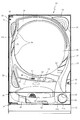
以下、本発明の第1の実施形態について、添付図面を参照して説明する。図1は、第1の実施形態におけるパチンコ機10の正面図であり、図2はパチンコ機10の遊技盤13の正面図であり、図3はパチンコ機10の背面図である。
DESCRIPTION OF EXEMPLARY EMBODIMENTS Hereinafter, a first embodiment of the invention will be described with reference to the accompanying drawings. FIG. 1 is a front view of a
パチンコ機10は、図1に示すように、略矩形状に組み合わせた木枠により外殻が形成される外枠11と、その外枠11と略同一の外形形状に形成され外枠11に対して開閉可能に支持された内枠12とを備えている。外枠11には、内枠12を支持するために正面視(図1参照)左側の上下2カ所に金属製のヒンジ18が取り付けられ、そのヒンジ18が設けられた側を開閉の軸として内枠12が正面手前側へ開閉可能に支持されている。
As shown in FIG. 1, the
内枠12には、多数の釘や入賞口63,64等を有する遊技盤13(図2参照)が裏面側から着脱可能に装着される。この遊技盤13の前面を球が流下することにより弾球遊技が行われる。なお、内枠12には、球を遊技盤13の前面領域に発射する球発射ユニット112a(図5参照)やその球発射ユニット112aから発射された球を遊技盤13の前面領域まで誘導する発射レール(図示せず)等が取り付けられている。
A game board 13 (see FIG. 2) having a large number of nails, winning
内枠12の前面側には、その前面上側を覆う前面枠14と、その下側を覆う下皿ユニット15とが設けられている。前面枠14及び下皿ユニット15を支持するために正面視(図1参照)左側の上下2カ所に金属製のヒンジ19が取り付けられ、そのヒンジ19が設けられた側を開閉の軸として前面枠14及び下皿ユニット15が正面手前側へ開閉可能に支持されている。なお、内枠12の施錠と前面枠14の施錠とは、シリンダ錠20の鍵穴21に専用の鍵を差し込んで所定の操作を行うことでそれぞれ解除される。
On the front side of the
前面枠14は、装飾用の樹脂部品や電気部品等を組み付けたものであり、その略中央部には略楕円形状に開口形成された窓部14cが設けられている。前面枠14の裏面側には2枚の板ガラスを有するガラスユニット16が配設され、そのガラスユニット16を介して遊技盤13の前面がパチンコ機10の正面側に視認可能となっている。
The
前面枠14には、球を貯留する上皿17が前方へ張り出して上面を開放した略箱状に形成されており、この上皿17に賞球や貸出球などが排出される。上皿17の底面は正面視(図1参照)右側に下降傾斜して形成され、その傾斜により上皿17に投入された球が球発射ユニット112aへと案内される。また、上皿17の上面には、枠ボタン22が設けられている。この枠ボタン22は、例えば、後述する第3図柄表示装置81(図2参照)で表示される演出のステージを変更したり、スーパーリーチの演出内容を変更したりする場合などに、遊技者により操作される。
On the
ステージとは、第3図柄表示装置81に表示される各種演出に統一性を持たせた演出モードのことで、本パチンコ機10では「街中ステージ」,「空ステージ」,「島ステージ」の3つのステージが設けられている。そして、後述する第1入球口64への入球(始動入賞)に伴って行われる変動演出やリーチ演出などの各種演出は、それぞれのステージに与えられたテーマに合わせて行われるように設計されている。ステージの変更は、変動演出が行われていない期間や高速変動中に遊技者によって枠ボタン22が操作された場合に行われ、枠ボタン22が操作される度に「街中ステージ」→「空ステージ」→「島ステージ」→「街中ステージ」→・・・の順で繰り返し変更される。また、電源投入後の直後は、初期ステージとして「街中ステージ」が設定される。
The stage is an effect mode in which the various effects displayed on the third
一方、第3図柄表示装置81には、ノーマルリーチ演出が開始された場合に、ノーマルリーチからスーパーリーチに発展させるときは、ノーマルリーチ中にスーパーリーチの演出態様の選択画面が表示されるように構成されており、その選択画面が表示されている間に、枠ボタン22が遊技者に操作されると、スーパーリーチ時の演出内容が変更される。
On the other hand, the 3rd
前面枠14には、その周囲(例えばコーナー部分)に各種ランプ等の発光手段が設けられている。これら発光手段は、大当たり時や所定のリーチ時等における遊技状態の変化に応じて、点灯又は点滅することにより発光態様が変更制御され、遊技中の演出効果を高める役割を果たす。窓部14cの周縁には、LED等の発光手段を内蔵した電飾部29〜33が設けられている。パチンコ機10においては、これら電飾部29〜33が大当たりランプ等の演出ランプとして機能し、大当たり時やリーチ演出時等には内蔵するLEDの点灯や点滅によって各電飾部29〜33が点灯または点滅して、大当たり中である旨、或いは大当たり一歩手前のリーチ中である旨が報知される。また、前面枠14の正面視(図1参照)左上部には、LED等の発光手段が内蔵され賞球の払い出し中とエラー発生時とを表示可能な表示ランプ34が設けられている。
The
また、右側の電飾部32下側には、前面枠14の裏面側を視認できるように裏面側より透明樹脂を取り付けて小窓35が形成され、遊技盤13前面の貼着スペースK1(図2参照)に貼付される証紙等はパチンコ機10の前面から視認可能とされている。また、パチンコ機10においては、より煌びやかさを醸し出すために、電飾部29〜33の周りの領域にクロムメッキを施したABS樹脂製のメッキ部材36が取り付けられている。
In addition, a
窓部14cの下方には、貸球操作部40が配設されている。貸球操作部40には、度数表示部41と、球貸しボタン42と、返却ボタン43とが設けられている。パチンコ機10の側方に配置されるカードユニット(球貸しユニット)(図示せず)に紙幣やカード等を投入した状態で貸球操作部40が操作されると、その操作に応じて球の貸出が行われる。具体的には、度数表示部41はカード等の残額情報が表示される領域であり、内蔵されたLEDが点灯して残額情報として残額が数字で表示される。球貸しボタン42は、カード等(記録媒体)に記録された情報に基づいて貸出球を得るために操作されるものであり、カード等に残額が存在する限りにおいて貸出球が上皿17に供給される。返却ボタン43は、カードユニットに挿入されたカード等の返却を求める際に操作される。なお、カードユニットを介さずに球貸し装置等から上皿17に球が直接貸し出されるパチンコ機、いわゆる現金機では貸球操作部40が不要となるが、この場合には、貸球操作部40の設置部分に飾りシール等を付加して部品構成は共通のものとしても良い。カードユニットを用いたパチンコ機と現金機との共通化を図ることができる。
A ball
上皿17の下側に位置する下皿ユニット15には、その中央部に上皿17に貯留しきれなかった球を貯留するための下皿50が上面を開放した略箱状に形成されている。下皿50の右側には、球を遊技盤13の前面へ打ち込むために遊技者によって操作される操作ハンドル51が配設され、かかる操作ハンドル51の内部には球発射ユニット112aの駆動を許可するためのタッチセンサ51aと、押下操作している期間中には球の発射を停止する押しボタン式の打ち止めスイッチ51bと、操作ハンドル51の回動操作量を電気抵抗の変化により検出する可変抵抗器(図示せず)とが内蔵されている。操作ハンドル51が遊技者によって右回りに回転操作されると、タッチセンサ51aがオンに設定されると共に可変抵抗器の抵抗値が操作量に対応して変化し、操作ハンドル51の回動操作量に応じて変化する可変抵抗器の抵抗値に対応した強さで球が発射され、これにより遊技者の操作に対応した飛び量で遊技盤13の前面へ球が打ち込まれる。また、操作ハンドル51が遊技者により操作されていない状態においては、タッチセンサ51aおよび打ち止めスイッチ51bがオフとなっている。
In the
下皿50の正面下方部には、下皿50に貯留された球を下方へ排出する際に操作するための球抜きレバー52が設けられている。この球抜きレバー52は、常時、右方向に付勢されており、その付勢に抗して左方向へスライドさせることにより、下皿50の底面に形成された底面口が開口して、その底面口から球が自然落下して排出される。かかる球抜きレバー52の操作は、通常、下皿50の下方に下皿50から排出された球を受け取る箱(一般に「千両箱」と称される)を置いた状態で行われる。下皿50の右方には、上述したように操作ハンドル51が配設され、下皿50の左方には灰皿53が取り付けられている。
In the lower part of the front of the
図2に示すように、遊技盤13は、正面視略正方形状に切削加工した木製のベース板60に、球案内用の多数の釘や風車およびレール61,62、一般入賞口63、第1入球口64、可変入賞装置65、可変表示装置ユニット80等を組み付けて構成され、その周縁部が内枠12の裏面側に取り付けられる。一般入賞口63、第1入球口64、可変入賞装置65、可変表示装置ユニット80は、ルータ加工によってベース板60に形成された貫通穴に配設され、遊技盤13の前面側から木ネジ等により固定されている。また、遊技盤13の前面中央部分は、前面枠14の窓部14c(図1参照)を通じて内枠12の前面側から視認することができる。以下に、主に図2を参照して、遊技盤13の構成について説明する。
As shown in FIG. 2, the
遊技盤13の前面には、帯状の金属板を略円弧状に屈曲加工して形成した外レール62が植立され、その外レール62の内側位置には外レール62と同様に帯状の金属板で形成した円弧状の内レール61が植立される。この内レール61と外レール62とにより遊技盤13の前面外周が囲まれ、遊技盤13とガラスユニット16(図1参照)とにより前後が囲まれることにより、遊技盤13の前面には、球の挙動により遊技が行われる遊技領域が形成される。遊技領域は、遊技盤13の前面であって2本のレール61,62と円弧部材70とにより区画して形成される略円形状の領域(入賞口等が配設され、発射された球が流下する領域)である。
An
2本のレール61,62は、球発射ユニット112a(図5参照)から発射された球を遊技盤13上部へ案内するために設けられたものである。内レール61の先端部分(図2の左上部)には戻り球防止部材68が取り付けられ、一旦、遊技盤13の上部へ案内された球が再度球案内通路内に戻ってしまうといった事態が防止される。外レール62の先端部(図2の右上部)には、球の最大飛翔部分に対応する位置に返しゴム69が取り付けられ、所定以上の勢いで発射された球は、返しゴム69に当たって、勢いが減衰されつつ中央部側へ跳ね返される。また、内レール61の右下側の先端部と外レール62の右上側の先端部との間には、レール間を繋ぐ円弧を内面側に設けて形成された樹脂製の円弧部材70がベース板60に打ち込んで固定されている。
The two
本パチンコ機10では、球が第1入球口64へ入球した場合に特別図柄(第1図柄)の抽選が行われ、球が第2入球口67を通過した場合に普通図柄(第2図柄)の抽選が行われる。第1入球口64への入球に対して行われる特別図柄の抽選では、特別図柄の大当たりか否かの当否判定が行われると共に、特別図柄の大当たりと判定された場合にはその大当たり種別の判定も行われる。特別図柄の大当たりになると、パチンコ機10が特別遊技状態へ移行すると共に、通常時には閉鎖されている特定入賞口65aが所定時間(例えば、30秒経過するまで、或いは、球が10個入賞するまで)開放され、その開放が5回(5ラウンド)繰り返される。その結果、その特定入賞口65aに多量の球が入賞するので、通常時より多量の賞球の払い出しが行われる。特別図柄の大当たり種別としては、「大当たりA」、「大当たりB」の2種類が設けられており、特別遊技状態の終了後には大当たり終了後の付加価値として、これらの大当たり種別に応じた遊技上の価値(遊技価値)が遊技者に付与される。
In the
また、特別図柄(第1図柄)の抽選が行われると、第1図柄表示装置37において特別図柄の変動表示が開始されて、所定時間(例えば、11秒〜60秒など)が経過した後に、抽選結果を示す特別図柄が停止表示される。第1図柄表示装置37において変動表示が行われている間に球が第1入球口64へ入球すると、その入球回数は最大4回まで保留され、その保留球数が第1図柄表示装置37により示されると共に、第3図柄表示装置81においても示される。第1図柄表示装置37において変動表示が終了した場合に、第1入球口64についての保留球数が残っていれば、次の特別図柄の抽選が行われると共に、その抽選に応じた変動表示が開始される。尚、パチンコ機10が特別遊技状態へ移行すると開閉される特別入賞口65aは、第1入球口64の直ぐ下に設けられている。よって、特別遊技状態中は、遊技者が特別入賞口65aに入賞させようとして球を打つので、第1入球口64にも球が多く入球する。従って、殆どの場合、パチンコ機10が特別遊技状態に移行している間に、第1入球口64についての保留球数は最大(4回)になる。
In addition, when the special symbol (the first symbol) is drawn, after the special symbol variable display is started on the first
一方、第2入球口67における球の通過に対して行われる普通図柄の抽選では、普通図柄の当たりか否かの当否判定が行われる。普通図柄の当たりになると、所定時間(例えば、0.2秒または1秒)だけ第1入球口64に付随する電動役物が開放され、第1入球口64へ球が入球し易い状態になる。つまり、普通図柄の当たりになると、球が第1入球口64へ入球し易くなり、その結果、特別図柄の抽選が行われ易くなる。
On the other hand, in the normal symbol lottery performed for the passage of the ball at the
また、普通図柄(第2図柄)の抽選が行われると、第2図柄表示装置83において普通図柄の変動表示が開始されて、所定時間(例えば、3秒や30秒など)が経過した後に、抽選結果を示す普通図柄が停止表示される。第2図柄表示装置83において変動表示が行われている間に球が第2入球口67を通過すると、その通過回数は最大4回まで保留され、その保留球数が第1図柄表示装置37により表示されると共に、第2図柄保留ランプ84においても示される。第2図柄表示装置83において変動表示が終了した場合に、第2入球口67についての保留球数が残っていれば、次の普通図柄の抽選が行われると共に、その抽選に応じた変動表示が開始される。
In addition, when the normal symbol (the second symbol) is drawn, the normal symbol variation display is started on the second
上述したように、特別図柄の大当たり種別としては、「大当たりA」、「大当たりB」の2種類が設けられている。 As described above, there are two types of special jackpot types, “Big Jack A” and “Big Jack B”.
「大当たりA」、「大当たりB」になるといずれも、ラウンド数16ラウンドの特別遊技状態(16R大当たり)となり、その後、大当たり終了後の付加価値として、「大当たりA」であれば、次に大当たりとなるまでの間はパチンコ機10が特別図柄の高確率状態(特別図柄の確変中)へ移行する。一方、「大当たりB」であれば、その大当たりが終了してから、100回、抽選が実行されるまで(特別図柄の変動が開始されるまで)の間、普通図柄の時短状態となる。
Both “Big Jack A” and “Big Jack B” will be in a special gaming state with 16 rounds (16R jackpot). After that, if the jackpot value is “Big Jack A”, Until that time, the
ここで、「特別図柄の高確率状態」とは、特別図柄の大当たり確率がアップした状態、いわゆる特別図柄の確率状態(特別図柄の確変中)をいい、換言すれば、特別遊技状態(16R大当たり)へ移行し易い遊技の状態のことである。対して、「特別図柄の高確率状態」でない場合を「特別図柄の低確率状態」といい、これは特別図柄の確変状態よりも大当たり確率が低い状態、即ち、特別図柄の大当たり確率が通常の状態(特別図柄の通常状態)のことを示す。また、「普通図柄の時短状態」(普通図柄の時短中)とは、普通図柄の当たり確率がアップして、第1入球口64へ球が入球し易い遊技の状態のことをいう。対して、「普通図柄の時短状態」でない時を「普通図柄の通常状態」といい、これは普通図柄の当たり確率が通常の状態、即ち、時短中よりも当たり確率が低い状態のことを示す。 Here, the “high probability state of the special symbol” means a state where the special symbol jackpot probability is increased, that is, a so-called special symbol probability state (during special symbol change), in other words, the special gaming state (16R jackpot) ) Is a game state that is easy to shift to. On the other hand, a case that is not a “high probability state of a special symbol” is called a “low probability state of a special symbol”, which has a lower probability of jackpot than the probability variation state of a special symbol, that is, the jackpot probability of a special symbol is normal. Indicates the state (normal state of special symbol). The “normal symbol time-short state” (ordinary symbol time-short state) means a game state in which the probability of hitting the normal symbol increases and the ball easily enters the first entrance 64. On the other hand, when it is not “normal symbol short-time state”, it is called “normal symbol normal state”, which indicates that the normal symbol hit probability is normal, that is, the hit probability is lower than during short-time. .
上述したように、本実施形態における特別図柄の大当たりでは、大当たりの種別に関わらず大当たり時のラウンド数と、特別図柄の確変期間とを共通とし、その大当たりの種別に応じて「普通図柄の時短状態」となる期間を変えている。これに対して、大当たりの種別に応じてラウンド数を変えても良いし、大当たりの種別の一部のみラウンド数を変えても良い。また、例えば、大当たりの種別に応じて「普通図柄の時短状態」となる期間を変える代わりに、第1入球口64に付随する電動役物(図示せず)を開放する時間や、1回の普通図柄の当たりで電動役物を開放する回数を変更するものとしても良い。また、本実施形態では、大当たり終了後に、「特別図柄の高確率状態」および「普通図柄の時短状態」となるが、「特別図柄の高確率状態」が終了した後に、「普通図柄の時短状態」となるように構成しても良い。 As described above, in the special symbol jackpot in this embodiment, regardless of the type of jackpot, the number of rounds at the jackpot and the probability variation period of the special symbol are common, The period of “state” is changed. On the other hand, the number of rounds may be changed according to the type of jackpot, or the number of rounds may be changed only for a part of the jackpot type. Also, for example, instead of changing the period when the “normal symbol time-short state” is changed according to the type of jackpot, the time for opening the electric accessory (not shown) associated with the first entrance 64 or once It is good also as what changes the frequency | count of opening an electrically-driven accessory in the hit of a normal symbol. Further, in this embodiment, after the jackpot ends, the “special symbol high probability state” and the “normal symbol short-time state”, but after the “special symbol high-probability state”, the “normal symbol short-time state” You may comprise so that it may become.
本パチンコ機10では、電源などの投入等により初期設定が行われると、必ず「特別図柄の低確率状態」に設定される。その後、特別図柄の大当たりになると、「特別図柄の高確率状態」へ移行すると共に、「普通図柄の時短状態」へ移行する。
In the
遊技領域の正面視右側上部(図2の右側上部)には、発光手段である複数の発光ダイオード(以下、「LED」と略す。)37aと7セグメント表示器37bとが設けられた第1図柄表示装置37が配設されている。第1図柄表示装置37は、後述する主制御装置110で行われる各制御に応じた表示がなされるものであり、主にパチンコ機10の遊技状態の表示が行われる。複数のLED37aは、第1入球口64への入球(始動入賞)に伴って行われる特別図柄の抽選が実行中であるか否かを点灯状態により示すことによって変動表示を行ったり、変動終了後の停止図柄として、その特別図柄の抽選結果に応じた特別図柄(第1図柄)を点灯状態により示したり、第1入球口64に入球された球のうち変動が未実行である球(保留球)の数である保留球数を点灯状態により示すものである。
A first pattern provided with a plurality of light emitting diodes (hereinafter abbreviated as “LEDs”) 37a and a 7-
この第1図柄表示装置37において特別図柄(第1図柄)の変動表示が行われている間に球が第1入球口64へ入球した場合、その入球回数は最大4回まで保留され、その保留球数は第1図柄表示装置37により示されると共に、第3図柄表示装置81においても示される。なお、本実施形態においては、第1入球口64への入球は、最大4回まで保留されるように構成したが、最大保留回数は4回に限定されるものでなく、3回以下、又は、5回以上の回数(例えば、8回)に設定しても良い。
If a ball enters the first entrance 64 while the special symbol (the first symbol) is being displayed on the first
7セグメント表示器37bは、大当たり中のラウンド数やエラー表示を行うものである。なお、LED37aは、それぞれのLEDの発光色(例えば、赤、緑、青)が異なるよう構成され、その発光色の組み合わせにより、少ないLEDでパチンコ機10の各種遊技状態(特別図柄の高確率状態や、普通図柄の時短中など)を表示することができる。また、LED37aには、変動終了後の停止図柄として特別図柄の抽選結果が大当たりであるか否かが示されるだけでなく、大当たりである場合はその大当たり種別(大当たりA、大当たりB)に応じた特別図柄(第1図柄)が示される。
The 7-
また、遊技領域には、球が入賞することにより5個から15個の球が賞球として払い出される複数の一般入賞口63が配設されている。また、遊技領域の中央部分には、可変表示装置ユニット80が配設されている。可変表示装置ユニット80には、液晶ディスプレイ(以下単に「表示装置」と略す。)で構成された第3図柄表示装置81と、LEDで構成された第2図柄表示装置83とが設けられている。この可変表示装置ユニット80には、第3図柄表示装置81の外周を囲むようにして、センターフレーム86が配設されている。
The game area is provided with a plurality of general winning
第3図柄表示装置81は、第1図柄表示装置37の表示に応じた装飾的な表示を行うものである。例えば、第1入球口64へ球が入球(始動入賞)すると、それをトリガとして、第1図柄表示装置37において特別図柄(第1図柄)の変動表示が実行される。更に、第3図柄表示装置81では、その特別図柄の変動表示に同期して、その特別図柄の変動表示に対応する第3図柄の変動表示が行われる。
The third
第3図柄表示装置81は、8インチサイズの大型の液晶ディスプレイで構成されるものであり、後述する表示制御装置114によって表示内容が制御されることにより、例えば左、中及び右の3つの図柄列が表示される。各図柄列は複数の図柄によって構成され、これらの図柄が図柄列毎に縦スクロールして第3図柄表示装置81の表示画面上にて第3図柄が可変表示されるようになっている。本実施形態では、主制御装置110の制御に伴った遊技状態の表示が第1図柄表示装置37で行われるのに対して、第3図柄表示装置81はその第1図柄表示装置37の表示に応じた装飾的な表示が行われる。なお、表示装置に代えて、例えば、リール等を用いて第3図柄表示装置81を構成するようにしても良い。
The third
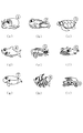
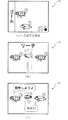
ここで、第3図柄表示装置81の表示内容について、図4及び図5を参照して詳細に説明する。図4は、第3図柄表示装置81にて変動表示される図柄を個々に示す図であり、図5は、第3図柄表示装置81の表示画面を示す図である。
Here, the display content of the 3rd
図4(a)〜(i)に示すように、絵柄の一種である図柄は、「1」〜「9」の数字が各々付された9種類の主図柄より構成されている。より詳しくは、タコ等の9種類のキャラクタ図柄に「1」〜「9」の数字がそれぞれ付されて主図柄が構成されている。 As shown in FIGS. 4A to 4I, a symbol which is a kind of pattern is composed of nine types of main symbols to which numbers “1” to “9” are respectively attached. More specifically, the main symbols are configured by attaching numbers “1” to “9” to nine types of character symbols such as octopus.
図5(a)に示すように、第3図柄表示装置81の表示画面(表示領域)には、表示領域として、図柄列Z1が横並びに3つ設定されている。図柄列Z1には、左図柄、中図柄、右図柄がそれぞれ、昇順に縦方向にスクロール表示される構成となっている。図柄列Z1に停止表示された図柄の組み合わせにより遊技者に遊技の大当たり(大当たり遊技が開始されること)を報知する構成となっている。
As shown in FIG. 5A, the display screen (display region) of the third
図5(b)に示すように、表示画面は、図柄列Z1に3個の図柄が停止表示されるようになっている。なお、本実施形態では、有効ラインは図柄列Z1のみとしたが、複数の有効ライン(例えば、表示画面に3つの横方向の有効ラインと2つの斜め方向の有効ライン)を設定するように構成してもよい。 As shown in FIG. 5B, the display screen is configured to stop and display three symbols in the symbol row Z1. In the present embodiment, the effective line is only the symbol row Z1, but a plurality of effective lines (for example, three horizontal effective lines and two diagonal effective lines) are set on the display screen. May be.
本パチンコ機10では、奇数番号(1,3,5,7,9)が付された主図柄は「確変図柄」に相当し、16R確変大当たりである大当たりAが発生する場合には、同一の確変図柄の組み合わせが停止表示される。また、偶数番号(2,4,6,8)が付された主図柄は、「通常図柄」に相当し、16R通常大当たりである大当たりBが発生する場合には、同一の通常図柄の組み合わせが停止表示される。
In this
なお、第3図柄表示装置81における図柄の変動表示の態様は、上記のものに限定されることはなく任意であり、図柄列の数、図柄列における図柄の変動表示の方向、各図柄列の図柄数などは適宜変更可能である。また、第3図柄表示装置81にて変動表示される絵柄は上記のような図柄に限られることはなく、例えば絵柄として数字のみが変動表示される構成としてもよい。
It should be noted that the mode of the variable display of the symbols in the third
図2に戻って、説明を続ける。第2図柄表示装置83は、球が第2入球口67を通過することに伴って行われる普通図柄の抽選が実行中であるか否かを点灯状態により示すことによって変動表示を行ったり、変動終了後の停止図柄として、その普通図柄の抽選結果に応じた普通図柄(第2図柄)を点灯状態により示すものである。
Returning to FIG. 2, the description will be continued. The second
より具体的には、第2図柄表示装置83では、球が第2入球口67を通過する毎に、第2図柄としての「○」の図柄と「×」の図柄とを交互に点灯させる変動表示が行われる。パチンコ機10は、第2図柄表示装置83における変動表示が所定図柄(本実施形態においては「○」の図柄)で停止すると、第1入球口64に付随する電動役物が所定時間だけ作動状態となり(開放される)、その結果、第1入球口64に球が入り易い状態となるように構成されている。球が第2入球口67を通過した通過回数は最大4回まで保留され、その保留球数が上述した第1図柄表示装置37により表示されると共に第2図柄保留ランプ84においても点灯表示される。第2図柄保留ランプ84は、最大保留数分の4つ設けられ、第3図柄表示装置81の下方に左右対称に配設されている。
More specifically, in the second
なお、普通図柄(第2図柄)の変動表示は、本実施形態のように、第2図柄表示装置83において複数のランプの点灯と非点灯を切り換えることにより行うものの他、第1図柄表示装置37及び第3図柄表示装置81の一部を使用して行うようにしても良い。同様に、第2図柄保留ランプ84の点灯を第3図柄表示装置81の一部で行うようにしても良い。また、第2入球口67における球の通過は、第1入球口64と同様に、最大保留球数は4回に限定されるものでなく、3回以下、又は、5回以上の回数(例えば、8回)に設定しても良い。また、第1図柄表示装置37により保留球数が示されるので、第2図柄保留ランプ84により点灯表示を行わないものとしても良い。
The normal symbol (second symbol) variable display is performed by switching on and off of a plurality of lamps in the second
可変表示装置ユニット80の下方には、球が入球し得る第1入球口64が配設されている。この第1入球口64へ球が入球すると遊技盤13の裏面側に設けられる第1入球口スイッチ(図示せず)がオンとなり、その第1入球口スイッチのオンに起因して主制御装置110で特別図柄の抽選がなされ、その抽選結果に応じた表示が第1図柄表示装置37のLED37aで示される。また、第1入球口64は、球が入球すると5個の球が賞球として払い出される入賞口の1つにもなっている。
Below the variable
第1入球口64の下方には可変入賞装置65が配設されており、その略中央部分に横長矩形状の特定入賞口(大開放口)65aが設けられている。パチンコ機10においては、主制御装置110で行われる特別図柄の抽選が大当たりとなると、所定時間(変動時間)が経過した後に、大当たりの停止図柄となるよう第1図柄表示装置37のLED37aを点灯させると共に、その大当たりに対応した第3図柄の停止図柄を第3図柄表示装置81に表示させて、大当たりの発生が示される。その後、通常時より多量の賞球の払い出しが行われる特別遊技状態(16ラウンドの大当たり)に遊技状態が遷移する。この特別遊技状態として、通常時には閉鎖されている特定入賞口65aが、所定時間(例えば、30秒経過するまで、或いは、球が10個入賞するまで)開放される。
A variable winning device 65 is disposed below the first ball opening 64, and a horizontally-long rectangular specific winning port (large opening) 65a is provided at a substantially central portion thereof. In the
この特定入賞口65aは、所定時間が経過すると閉鎖され、その閉鎖後、再度、その特定入賞口65aが所定時間開放される。この特定入賞口65aの開閉動作は、16回(16ラウンド)繰り返し可能にされている。この開閉動作が行われている状態が、遊技者にとって有利な特別遊技状態の一形態であり、遊技者には、遊技上の価値(遊技価値)の付与として通常時より多量の賞球の払い出しが行われる。
The
可変入賞装置65は、具体的には、特定入賞口65aを覆う横長矩形状の開閉板と、その開閉板の下辺を軸として前方側に開閉駆動するための大開放口ソレノイド(図示せず)とを備えている。特定入賞口65aは、通常時は、球が入賞できないか又は入賞し難い閉状態になっている。大当たりの際には大開放口ソレノイドを駆動して開閉板を前面下側に傾倒し、球が特定入賞口65aに入賞しやすい開状態を一時的に形成し、その開状態と通常時の閉状態との状態を交互に繰り返すように作動する。
Specifically, the variable winning device 65 is a horizontally long rectangular opening / closing plate covering the specific winning
なお、上記した形態に特別遊技状態は限定されるものではない。特定入賞口65aとは別に開閉される大開放口を遊技領域に設け、第1図柄表示装置37において大当たりに対応したLED37aが点灯した場合に、特定入賞口65aが所定時間開放され、その特定入賞口65aの開放中に、球が特定入賞口65a内へ入賞することを契機として特定入賞口65aとは別に設けられた大開放口が所定時間、所定回数開放される遊技状態を特別遊技状態として形成するようにしても良い。
Note that the special gaming state is not limited to the above-described form. When the game area is provided with a large opening that is opened and closed separately from the specific winning
遊技盤13の下側における左右の隅部には、証紙や識別ラベル等を貼着するための貼着スペースK1,K2が設けられ、貼着スペースK1に貼られた証紙等は、前面枠14の小窓35(図1参照)を通じて視認することができる。
Adhesive spaces K1 and K2 for adhering certificate stamps, identification labels, and the like are provided at the left and right corners on the lower side of the
更に、遊技盤13には、アウト口66が設けられている。いずれの入賞口63,64,65aにも入球しなかった球はアウト口66を通って図示しない球排出路へと案内される。遊技盤13には、球の落下方向を適宜分散、調整等するために多数の釘が植設されているとともに、風車等の各種部材(役物)が配設されている。
Further, the
図3に示すように、パチンコ機10の背面側には、制御基板ユニット90,91と、裏パックユニット94とが主に備えられている。制御基板ユニット90は、主基板(主制御装置110)と音声ランプ制御基板(音声ランプ制御装置113)と表示制御基板(表示制御装置114)とが搭載されてユニット化されている。制御基板ユニット91は、払出制御基板(払出制御装置111)と発射制御基板(発射制御装置112)と電源基板(電源装置115)とカードユニット接続基板116とが搭載されてユニット化されている。
As shown in FIG. 3,
裏パックユニット94は、保護カバー部を形成する裏パック92と払出ユニット93とがユニット化されている。また、各制御基板には、各制御を司る1チップマイコンとしてのMPU、各種機器との連絡をとるポート、各種抽選の際に用いられる乱数発生器、時間計数や同期を図る場合などに使用されるクロックパルス発生回路等が、必要に応じて搭載されている。
The
なお、主制御装置110、音声ランプ制御装置113及び表示制御装置114、払出制御装置111及び発射制御装置112、電源装置115、カードユニット接続基板116は、それぞれ基板ボックス100〜104に収納されている。基板ボックス100〜104は、ボックスベースと該ボックスベースの開口部を覆うボックスカバーとを備えており、そのボックスベースとボックスカバーとが互いに連結されて、各制御装置や各基板が収納される。
The
また、基板ボックス100(主制御装置110)及び基板ボックス102(払出制御装置111及び発射制御装置112)は、ボックスベースとボックスカバーとを封印ユニット(図示せず)によって開封不能に連結(かしめ構造による連結)している。また、ボックスベースとボックスカバーとの連結部には、ボックスベースとボックスカバーとに亘って封印シール(図示せず)が貼着されている。この封印シールは、脆性な素材で構成されており、基板ボックス100,102を開封するために封印シールを剥がそうとしたり、基板ボックス100,102を無理に開封しようとすると、ボックスベース側とボックスカバー側とに切断される。よって、封印ユニット又は封印シールを確認することで、基板ボックス100,102が開封されたかどうかを知ることができる。
Further, the substrate box 100 (main control device 110) and the substrate box 102 (dispensing
払出ユニット93は、裏パックユニット94の最上部に位置して上方に開口したタンク130と、タンク130の下方に連結され下流側に向けて緩やかに傾斜するタンクレール131と、タンクレール131の下流側に縦向きに連結されるケースレール132と、ケースレール132の最下流部に設けられ、払出モータ216(図5参照)の所定の電気的構成により球の払出を行う払出装置133とを備えている。タンク130には、遊技ホールの島設備から供給される球が逐次補給され、払出装置133により必要個数の球の払い出しが適宜行われる。タンクレール131には、当該タンクレール131に振動を付加するためのバイブレータ134が取り付けられている。
The
また、払出制御装置111には状態復帰スイッチ120が設けられ、発射制御装置112には可変抵抗器の操作つまみ121が設けられ、電源装置115にはRAM消去スイッチ122が設けられている。状態復帰スイッチ120は、例えば、払出モータ216(図5参照)部の球詰まり等、払出エラーの発生時に球詰まりを解消(正常状態への復帰)するために操作される。操作つまみ121は、発射ソレノイドの発射力を調整するために操作される。RAM消去スイッチ122は、パチンコ機10を初期状態に戻したい場合に電源投入時に操作される。
The
<先読み演出について>
本実施形態のパチンコ機10では、特別図柄の保留球に対して、第1入球口64に遊技球が入球して各種カウンタが取得されたことに基づいて、各種情報(当否、停止種別、変動パターン)が事前に判定(先読み)される。先読みが終了すると、先読みにより得られた各種情報(当否、停止種別、変動パターン)を含む入賞情報コマンド(大当たり入賞コマンドまたは外れ入賞コマンド)が音声ランプ制御装置113へ送信される。音声ランプ制御装置113のMPU221は、入賞情報コマンドを受信すると、先読み演出を実行するか否かを決定する。なお、先読み演出の詳細については、後述するための詳細については省略する。
<About pre-reading production>
In the
<パチンコ機10の電気的構成>
次に、図8を参照して、本パチンコ機10の電気的構成について説明する。図8は、パチンコ機10の電気的構成を示すブロック図である。
<Electric configuration of
Next, the electrical configuration of the
<主制御装置110の電気的構成>
主制御装置110には、演算装置である1チップマイコンとしてのMPU201が搭載されている。MPU201には、該MPU201により実行される各種の制御プログラムや固定値データを記憶したROM202と、そのROM202内に記憶される制御プログラムの実行に際して各種のデータ等を一時的に記憶するためのメモリであるRAM203と、そのほか、割込回路やタイマ回路、データ送受信回路などの各種回路が内蔵されている。なお、払出制御装置111や音声ランプ制御装置113などのサブ制御装置に対して動作を指示するために、主制御装置110から該サブ制御装置へ各種のコマンドがデータ送受信回路によって送信されるが、かかるコマンドは、主制御装置110からサブ制御装置へ一方向にのみ送信される。
<Electrical configuration of
The
主制御装置110のMPU201のROM202には、図11に示すように、大当たり乱数テーブル202a、大当たり種別テーブル202b、普通図柄当たり乱数テーブル202c、大当たり用変動パターンテーブル202d、外れ用変動パターンテーブル202eがそれぞれ設けられている。なお、本実施形態では、ROM202に設定されているデータテーブルの一例として、上記を挙げたが、その他のデータテーブルやプログラム等も記憶されている。上記した各種データテーブルについては、下記各種カウンタを説明する上で、詳細について説明する。
In the
主制御装置110では、特別図柄の抽選、普通図柄の抽選、第1図柄表示装置37における表示の設定、第2図柄表示装置83における表示の設定、および、第3図柄表示装置81における表示の設定といったパチンコ機10の主要な処理を実行する。そして、RAM203には、これらの処理を制御するための各種カウンタが設けられている。ここで、図9を参照して、主制御装置110のRAM203内に設けられるカウンタ等について説明する。これらのカウンタ等は、特別図柄の抽選、普通図柄の抽選、第1図柄表示装置37における表示の設定、第2図柄表示装置83における表示の設定、および、第3図柄表示装置81における表示の設定などを行うために、主制御装置110のMPU201で使用される。
In
特別図柄の抽選や、第1図柄表示装置37および第3図柄表示装置81の表示の設定には、特別図柄の抽選に使用する第1当たり乱数カウンタC1と、特別図柄の大当たり種別を選択するために使用する第1当たり種別カウンタC2と、特別図柄における外れの停止種別を選択するために使用する停止種別選択カウンタC3と、第1当たり乱数カウンタC1の初期値設定に使用する第1初期値乱数カウンタCINI1と、変動パターン選択に使用する変動種別カウンタCS1とが用いられる。また、普通図柄の抽選には、第2当たり乱数カウンタC4が用いられ、第2当たり乱数カウンタC4の初期値設定には第2初期値乱数カウンタCINI2が用いられる。これら各カウンタは、更新の都度、前回値に1が加算され、最大値に達した後0に戻るループカウンタとなっている。
In order to select a special symbol lottery and the first symbol random number counter C1 used for the special symbol lottery and the special symbol lottery for setting the display of the first
各カウンタは、例えば、タイマ割込処理(図18参照)の実行間隔である2ミリ秒間隔で更新され、また、一部のカウンタは、メイン処理(図26参照)の中で不定期に更新されて、その更新値がRAM203の所定領域に設定されたカウンタ用バッファに適宜格納される。RAM203には、1つの実行エリアと4つの保留エリア(保留第1〜第4エリア)とからなる特別図柄保留球格納エリア203aが設けられており、これらの各エリアには、第1入球口64への入球タイミングに合わせて、第1当たり乱数カウンタC1、第1当たり種別カウンタC2、停止種別選択カウンタC3、変動種別カウンタCS1の各値がそれぞれ格納される。また、RAM203には、1つの実行エリアと4つの保留エリア(保留第1〜第4エリア)とからなる普通図柄保留球格納エリア203bが設けられており、これらの各エリアには、球が左右何れかの第2入球口(スルーゲート)67を通過したタイミングに合わせて、第2当たり乱数カウンタC4の値が格納される。
Each counter is updated, for example, at an interval of 2 milliseconds, which is the execution interval of the timer interrupt process (see FIG. 18), and some counters are updated irregularly in the main process (see FIG. 26). Then, the updated value is appropriately stored in a counter buffer set in a predetermined area of the
各カウンタについて詳しく説明する。第1当たり乱数カウンタC1は、所定の範囲(例えば、0〜299)内で順に1ずつ加算され、最大値(例えば、0〜299の値を取り得るカウンタの場合は299)に達した後0に戻る構成となっている。特に、第1当たり乱数カウンタC1が1周した場合、その時点の第1初期値乱数カウンタCINI1の値が当該第1当たり乱数カウンタC1の初期値として読み込まれる。 Each counter will be described in detail. The first per-random number counter C1 is incremented by 1 within a predetermined range (for example, 0 to 299) and reaches 0 after reaching the maximum value (for example, 299 for a counter that can take a value of 0 to 299). It is the composition which returns to. In particular, when the first random number counter C1 makes one round, the value of the first initial value random number counter CINI1 at that time is read as the initial value of the first random number counter C1.
また、第1初期値乱数カウンタCINI1は、第1当たり乱数カウンタC1と同一範囲で更新されるループカウンタとして構成される。即ち、例えば、第1当たり乱数カウンタC1が0〜299の値を取り得るループカウンタである場合には、第1初期値乱数カウンタCINI1もまた、0〜299の範囲のループカウンタである。この第1初期値乱数カウンタCINI1は、タイマ割込処理(図18参照)の実行毎に1回更新されると共に、メイン処理(図26参照)の残余時間内で繰り返し更新される。 The first initial value random number counter CINI1 is configured as a loop counter that is updated in the same range as the first random number counter C1. That is, for example, when the first random number counter C1 is a loop counter that can take a value of 0 to 299, the first initial value random number counter CINI1 is also a loop counter in the range of 0 to 299. The first initial value random number counter CINI1 is updated once every execution of the timer interrupt process (see FIG. 18) and is repeatedly updated within the remaining time of the main process (see FIG. 26).
第1当たり乱数カウンタC1の値は、例えば定期的に(本実施形態ではタイマ割込処理毎に1回)更新され、球が第1入球口64に入賞したタイミングでRAM203の特別図柄保留球格納エリア203aに格納される。そして、特別図柄の大当たりとなる乱数の値は、主制御装置110のROM202に格納される大当たり乱数テーブル202a(図11参照)によって設定されており、第1当たり乱数カウンタC1の値が、大当たり乱数テーブル202aによって設定された大当たりとなる乱数の値と一致する場合に、特別図柄の大当たりと判定する。また、この大当たり乱数テーブル202aは、特別図柄の低確率時(特別図柄の低確率状態である期間)用と、その低確率時より特別図柄の大当たりとなる確率の高い高確率時(特別図柄の高確率状態である期間)用との2種類に分けられ、それぞれに含まれる大当たりとなる乱数の個数が異なって設定されている。このように、大当たりとなる乱数の個数を異ならせることにより、特別図柄の低確率時と特別図柄の高確率時とで、大当たりとなる確率が変更される。尚、特別図柄の高確率時用の大当たり乱数テーブル202aと、特別図柄の低確率時用の大当たり乱数テーブル202aとは、主制御装置110のROM202内に設けられている。
The value of the first random number counter C1 is updated, for example, periodically (in this embodiment, once for each timer interrupt process), and the special symbol holding ball in the
第1当たり種別カウンタC2は、特別図柄の大当たりとなった場合に、第1図柄表示装置37の表示態様を決定するものであり、所定の範囲(例えば、0〜99)内で順に1ずつ加算され、最大値(例えば、0〜99の値を取り得るカウンタの場合は99)に達した後0に戻る構成となっている。第1当たり種別カウンタC2の値は、例えば、定期的に(本実施形態ではタイマ割込処理毎に1回)更新され、球が第1入球口64に入賞したタイミングでRAM203の特別図柄保留球格納エリア203aに格納される。
The first hit type counter C2 determines the display mode of the first
ここで、特別図柄保留球格納エリア203aに格納された第1当たり乱数カウンタC1の値が、特別図柄の大当たりとなる乱数でなければ、即ち、特別図柄の外れとなる乱数であれば、第1図柄表示装置37に表示される停止図柄に対応した表示態様は、特別図柄の外れ時のものとなる。
Here, if the value of the first per-random number counter C1 stored in the special symbol reserved
一方で、特別図柄保留球格納エリア203aに格納された第1当たり乱数カウンタC1の値が、特別図柄の大当たりとなる乱数であれば、第1図柄表示装置37に表示される停止図柄に対応した表示態様は、特別図柄の大当たり時のものとなる。この場合、その大当たり時の具体的な表示態様は、同じ特別図柄保留球格納エリア203aに格納されている第1当たり種別カウンタC2の値が示す表示態様となる。
On the other hand, if the value of the first per-random number counter C1 stored in the special symbol holding
本実施形態のパチンコ機10における第1当たり乱数カウンタC1は、0〜299の範囲の2バイトのループカウンタとして構成されている。この第1当たり乱数カウンタC1において、特別図柄の低確率時に、特別図柄の大当たりとなる乱数値は3個あり、その乱数値である「7,107,282」は、低確率時用の大当たり乱数テーブル202aに格納されている。このように特別図柄の低確率時には、乱数値の総数が300ある中で、大当たりとなる乱数値の総数が3なので、特別図柄の大当たりとなる確率は、「1/100」となる。
The first random number counter C1 in the
一方で、特別図柄の高確率時に、特別図柄の大当たりとなる乱数値は30個あり、その値である「4,11,28,38,45,52,64,78,83,99,106,112,122,134,140,151,168,176,183,197,207,218,222,231,249,256,263,270,285,299」は、高確率時用の大当たり乱数テーブル202aに格納されている。このように特別図柄の高確率時には、乱数値の総数が300ある中で、大当たりとなる乱数値の総数が30なので、特別図柄の大当たりとなる確率は、「1/10」となる。 On the other hand, when there is a high probability of a special symbol, there are 30 random numbers that are jackpots of the special symbol, which are “4, 11, 28, 38, 45, 52, 64, 78, 83, 99, 106, 112, 122, 134, 140, 151, 168, 176, 183, 197, 207, 218, 222, 231, 249, 256, 263, 270, 285, 299 ”are stored in the jackpot random number table 202a for high probability. Stored. Thus, when the special symbol has a high probability, the total number of random numbers that are jackpots is 30 among the total number of random number values, so the probability that the special symbol is jackpot is “1/10”.
尚、本実施形態では、低確率時用の大当たり乱数テーブル202aに格納されている大当たりとなる乱数値と、高確率時用の大当たり乱数テーブル202aに格納されている大当たりとなる乱数値とで、重複した値とならないように、それぞれの大当たりとなる乱数値を設定している。ここで、大当たりとなる乱数値としてパチンコ機10の状況にかかわらず常に用いられる値が存在すれば、その乱数値が外部より入力されて、不正に大当たりを引き当てられやすくなるおそれがある。これに対して、本実施形態のように、状況に応じて(即ち、パチンコ機10が特別図柄の高確率状態か、特別図柄の低確率状態かに応じて)、大当たりとなる乱数値を変えることで、特別図柄の大当たりとなる乱数値が予測され難くすることができるので、不正に対する抑制を図ることができる。
In the present embodiment, the jackpot random number value stored in the jackpot random number table 202a for low probability and the jackpot random number value stored in the jackpot random number table 202a for high probability are: Random numbers that are big hits are set to avoid duplicate values. Here, if there is a value that is always used as a jackpot random value regardless of the situation of the
また、本実施形態のパチンコ機10における第1当たり種別カウンタC2の値は、0〜99の範囲のループカウンタとして構成されている。そして、図10(a)に示すように、この第1当たり種別カウンタC2において、乱数値が「0〜59」であった場合の大当たり種別は、「大当たりA」となる。また、値が「60〜99」であった場合の大当たり種別は、「大当たりB」となる。
Further, the value of the first hit type counter C2 in the
このように、本実施形態のパチンコ機10は、第1当たり種別カウンタC2が示す乱数の値によって、2種類の当たり種別(大当たりA、大当たりB)が決定されるように構成されている。尚、第1当たり種別カウンタC2の値(乱数値)から、特別図柄の大当たり種別を決定するための乱数値は、大当たり種別テーブル202bにより設定されており、このテーブルは、主制御装置110のROM202内に設けられている。
As described above, the
停止種別選択カウンタC3は、例えば0〜99の範囲内で順に1ずつ加算され、最大値(つまり99)に達した後0に戻る構成となっている。本実施形態では、停止種別選択カウンタC3によって、第3図柄表示装置81で表示される外れ時の停止種別が選択され、リーチが発生した後、最終停止図柄がリーチ図柄の前後に1つだけずれて停止する「前後外れリーチ」(例えば98,99)と、同じくリーチ発生した後、最終停止図柄がリーチ図柄の前後以外で停止する「前後外れ以外リーチ」(例えば90〜97の範囲)と、リーチ発生しない「完全外れ」(例えば0〜89の範囲)との3つの停止(演出)パターンが選択される。停止種別選択カウンタC3の値は、例えば定期的に(本実施形態ではタイマ割込処理毎に1回)更新され、球が第1入球口64に入賞したタイミングでRAM203の特別図柄保留球格納エリア203aに格納される。
For example, the stop type selection counter C3 is incremented by 1 within a range of 0 to 99, for example, and reaches a maximum value (that is, 99) and then returns to 0. In the present embodiment, the stop type at the time of release displayed on the third
尚、停止種別選択カウンタC3の値(乱数値)から、特別図柄の停止種別を決定するための乱数値は、停止種別選択テーブル(図示せず)により設定されており、このテーブルは、主制御装置110のROM202内に設けられている。また、本実施形態ではこのテーブルを、特別図柄の高確率時用と、特別図柄の低確率時用とに分けており、テーブルに応じて、外れの停止種別ごとに設定される乱数値の範囲を変えている。これは、パチンコ機10が特別図柄の高確率状態であるか、特別図柄の低確率状態であるか等に応じて、停止種別の選択比率を変更するためである。
The random value for determining the stop type of the special symbol from the value (random number value) of the stop type selection counter C3 is set by a stop type selection table (not shown). It is provided in the
例えば、高確率状態では、大当たりが発生し易いため必要以上にリーチ演出が選択されないように、「完全外れ」の停止種別に対応した乱数値の範囲が0〜89と広い高確率時用のテーブルが選択され、「完全外れ」が選択され易くなる。このテーブルは、「前後外れリーチ」が98,99と狭くなると共に「前後外れ以外リーチ」も90〜97と狭くなり、「前後外れリーチ」や「前後外れ以外リーチ」が選択され難くなる。また、低確率状態であれば、第1入球口64への球の入球時間を確保するために「完全外れ」の停止種別に対応した乱数値の範囲が0〜79と狭い低確率時用のテーブルが選択され、「完全外れ」が選択され難くなる。 For example, in a high-probability state, a table for a high-probability time with a wide range of random values from 0 to 89 corresponding to the stop type “completely out” is selected so that a reach effect is not selected more than necessary because a big hit is likely to occur. Is selected, and “completely off” is easily selected. In this table, the “front / rear detachment reach” is narrowed to 98,99 and the “reach other than front / rear detachment” is also narrowed to 90 to 97, making it difficult to select “rearward / rearward detachment reach” and “reach other than front / rear detachment”. In the low probability state, the random value range corresponding to the stop type “completely off” is 0 to 79 and the probability is low so as to secure the time for entering the ball into the first entrance 64. Table is selected, and “completely out” is difficult to select.
この停止種別選択テーブルは、「前後外れ以外リーチ」の停止種別に対応した乱数値の範囲が80〜97と広くなり、「前後外れ以外リーチ」が選択され易くなっている。よって、低確率状態では、演出時間の長いリーチ表示を多く行うことできるので、第1入球口64への球の入球時間を確保でき、第3図柄表示装置81による変動表示が継続して行われ易くなる。尚、後者のテーブルにおいても、「前後外れリーチ」の停止種別に対応した乱数値の範囲は98,99に設定される。
In this stop type selection table, the range of random values corresponding to the stop type of “reach other than front / rear out” is widened to 80 to 97, and “reach other than front / rear out” is easily selected. Therefore, in the low probability state, it is possible to perform a lot of reach display with a long production time, so it is possible to secure the time for entering the ball into the first entrance 64 and the variable display by the third
変動種別カウンタCS1は、例えば0〜198の範囲内で順に1ずつ加算され、最大値(つまり198)に達した後0に戻る構成となっている。第1入球口64に遊技球が入球したタイミングで取得されて、主制御装置110のRAM203の特別図柄保留球格納エリア203aに格納される。変動種別カウンタCS1によって、いわゆるノーマルリーチ、スーパーリーチ等の大まかな表示態様が決定される。表示態様の決定は、具体的には、図柄変動の変動時間の決定である。変動種別カウンタCS1により決定された変動時間に基づいて、音声ランプ制御装置113や表示制御装置114により第3図柄表示装置81で表示される第3図柄のリーチ種別や細かな図柄変動態様が決定される。変動種別カウンタCS1の値は、後述するメイン処理(図26参照)が1回実行される毎に1回更新され、当該メイン処理内の残余時間内でも繰り返し更新される。尚、変動種別カウンタCS1の値(乱数値)から、図柄変動の変動時間を一つ決定する乱数値を格納した変動パターンテーブル202d,202eは、主制御装置110のROM202内に設けられている。
The variation type counter CS1 is, for example, incremented by 1 within a range of 0 to 198, and returns to 0 after reaching the maximum value (that is, 198). It is acquired at the timing when a game ball enters the first entrance 64 and is stored in the special symbol reservation
変動パターンテーブルには、大当たり用変動パターンテーブル202dと外れ用変動パターンテーブル202e(図11参照)とがそれぞれ設定されている。例えば、外れ用変動パターンテーブル202eには、「外れ(長時間用)」、「外れ(短時間用)」、「外れノーマルリーチ」各種、「外れスーパーリーチ」各種、「外れスペシャルリーチ」各種が規定され、大当たりA・大当たりB共用の大当たり用変動パターンテーブル202dには、「共用ノーマルリーチ」各種、「共用スーパーリーチ」各種、「共用スペシャルリーチ」各種が規定されている。なお、ここで、外れ用の変動パターンの1つとして、外れ会話予告変動パターンが設定されている。また「共用スーパーリーチ」各種の1つとして当たり会話予告変動パターンが設定されている。そして、変動パターンテーブルに規定された各種変動パターンから、予測された抽選結果や、予測された停止種別(大当たりの場合には大当たり種別)に応じて変動パターンが選定される。 In the variation pattern table, a big hit variation pattern table 202d and a deviation variation pattern table 202e (see FIG. 11) are set. For example, in the variation pattern table 202e for detachment, “displacement (for a long time)”, “detachment (for a short time)”, “reason normal reach”, “reason superreach”, and “reason special reach” are defined. In the jackpot variation pattern table 202d for jackpot A and jackpot B, “common normal reach”, “shared super reach”, and “shared special reach” are defined. Here, an off-conversation notice change pattern is set as one of the off-change patterns. In addition, as one of the various types of “shared super reach”, a conversation notice variation pattern is set. Then, a variation pattern is selected from the various variation patterns defined in the variation pattern table according to the predicted lottery result and the predicted stop type (a jackpot type in the case of a jackpot).
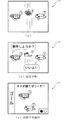
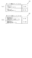
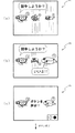
図6(a)〜(c)及び図7(a)〜(b)は、外れ会話予告変動パターンまたは当たり会話予告変動パターンの一例を模式的に示した図である。第3図柄表示装置81に第3図柄の変動が開始された後に、図6(a)に示すように、左図柄と右図柄にそれぞれ第3図柄が仮停止して表示され、中図柄は高速または低速で変動している状態となる。図6(a)に示すように、左図柄と右図柄とは異なる図柄で仮停止(非リーチ状態で仮停止)される。
FIGS. 6A to 6C and FIGS. 7A to 7B are diagrams schematically showing an example of a missed conversation notice variation pattern or a hit conversation notice variation pattern. After the change of the 3rd symbol is started on the 3rd
図6(b)に示すように、左図柄に停止している第3図柄のキャラクタ(本実施形態では、カメのキャラクタ)よりコメントが吹き出し(コメントウインドウ)により表示される。また、その後、右図柄に停止している第3図柄のキャラクタ(本実施形態では、イルカのキャラクタ)より左図柄のコメントに対する会話のコメントが吹き出しによって表示される。このように、外れ会話予告変動パターンまたは当たり会話予告変動パターンでは、左図柄と右図柄とに仮停止した図柄により会話をする予告表示が実行される。図6(b)に示すように会話の内容が成立している場合には、図6(c)に示すように、リーチとなるか否かの演出予告が実行される。本実施形態では、図6(b)に示すように、左図柄のキャラクタが「競争しようか?」というコメントに対して、右図柄のキャラクタが「いいよ!!」という会話が成立するコメントをしたので、会話が成立したことを示している。 As shown in FIG. 6B, a comment is displayed by a balloon (comment window) from a character of the third symbol (in this embodiment, a turtle character) stopped on the left symbol. After that, a conversation comment for the left symbol comment is displayed by a balloon from the third symbol character (in this embodiment, a dolphin character) stopped in the right symbol. As described above, in the out-of-context notice fluctuation pattern or the hit conversation notice fluctuation pattern, the notice display for performing conversation using the symbols temporarily stopped on the left symbol and the right symbol is executed. When the content of the conversation is established as shown in FIG. 6 (b), an advance notice of whether or not to reach is executed as shown in FIG. 6 (c). In the present embodiment, as shown in FIG. 6B, in response to a comment that the left symbol character is “Let's compete?”, The right symbol character is a comment that establishes a conversation “OK!”. As a result, the conversation has been established.
なお、会話が成立しない場合には、図7(c)に示すように、左図柄のキャラクタの会話に対して、右図柄のキャラクタが何も返事をしない「・・・」が表示される。また、本実施形態では、右図柄のキャラクタが何も返事をしないことで会話が不成立となることを示したがそれに限らず、右図柄のキャラクタが「やだ!!」というコメントをした場合にも、会話が不成立であった事に該当する。また、本実施形態に挙げた内容に限らず、左図柄と右図柄との会話の内容が合致しない場合に会話が不成立であったことを示せば良い。 When the conversation is not established, as shown in FIG. 7C, “...” is displayed in which the right symbol character does not respond to the conversation of the left symbol character. Further, in the present embodiment, it is shown that the conversation is not established because the right symbol character does not answer anything. However, the present invention is not limited to this, and the right symbol character makes a comment “Yada!”. Corresponds to the fact that the conversation was not established. Further, the present invention is not limited to the content described in the present embodiment, and it is only necessary to show that the conversation is not established when the content of the conversation between the left symbol and the right symbol does not match.
会話が成立した場合には、図6(c)に示すように、左図柄のキャラクタ「カメ」と右図柄のキャラクタ「サメ」がゴールに向けて競争をする表示態様が表示される。そして、図7(a)に示すように、左図柄のキャラクタ「カメ」が右図柄のキャラクタ「サメ」よりも先にゴールに到達すると、図7(b)に示すように左図柄と右図柄に「カメ」の第3図柄が表示され、リーチ状態となる。即ち、会話予告は、リーチとなるか否かを遊技者に報知するための予告表示態様である。その後、外れ会話予告変動パターンまたは当たり会話予告変動パターンでは、ノーマルリーチやスーパーリーチ等の予め定められた変動表示態様(動的表示態様)が表示される。 When the conversation is established, as shown in FIG. 6C, a display mode is displayed in which the character “turtle” with the left symbol and the character “shark” with the right symbol compete toward the goal. When the left symbol character “turtle” reaches the goal before the right symbol character “shark” as shown in FIG. 7A, the left symbol and right symbol as shown in FIG. The 3rd symbol of “turtle” is displayed on the screen and the reach state is reached. That is, the conversation notice is a notice display mode for notifying the player whether or not the reach is reached. Thereafter, in the off-conversation notice change pattern or the hit conversation notice change pattern, a predetermined change display mode (dynamic display mode) such as normal reach or super reach is displayed.
なお、会話内容が成立しない場合、または、会話内容が成立しても、その後の予告演出によりリーチ状態とならなかった場合には、定められた中図柄が停止して、抽選結果が外れであったことが報知される。このように、当たり会話予告変動パターンでは、必ずリーチ状態となるように構成される。また、外れ会話予告変動パターンは、リーチ状態となる場合もリーチ状態とならない場合も両方設定されており、抽選により選択された外れ会話予告パターンにより異なるように構成されている。 If the content of the conversation is not established, or if the content of the conversation is established but does not reach the reach state due to the subsequent announcement effect, the determined middle symbol stops and the lottery result is out. It will be notified. Thus, the hit conversation notice variation pattern is always configured to reach a reach state. Further, the off conversation notice variation pattern is set both when the reach state is reached and when the reach state is not reached, and is configured to be different depending on the off conversation notice pattern selected by lottery.
このように、会話予告が実行されると、遊技者は、会話が成立して大当たりとなることを期待できる。よって、会話予告が実行される変動が開始されることを期待して遊技を行うことができ、遊技に早期に飽きてしまうのを防止できる。 In this way, when the conversation notice is executed, the player can expect that the conversation will be established and become a big hit. Therefore, it is possible to play a game in the hope that a change in which the conversation notice is executed is started, and it is possible to prevent the game from getting bored early.
第2当たり乱数カウンタC4は、例えば0〜239の範囲内で順に1ずつ加算され、最大値(つまり239)に達した後0に戻るループカウンタとして構成されている。また、第2当たり乱数カウンタC4が1周した場合、その時点の第2初期値乱数カウンタCINI2の値が当該第2当たり乱数カウンタC4の初期値として読み込まれる。第2当たり乱数カウンタC4の値は、本実施形態ではタイマ割込処理毎に、例えば定期的に更新され、球が左右何れかの第2入球口(スルーゲート)67を通過したことが検知された時に取得され、RAM203の普通図柄保留球格納エリア203bに格納される。
The second random number counter C4 is configured as a loop counter that is incremented one by one within a range of, for example, 0 to 239 and returns to 0 after reaching the maximum value (that is, 239). Further, when the second random number counter C4 makes one round, the value of the second initial value random number counter CINI2 at that time is read as the initial value of the second random number counter C4. In this embodiment, the value of the second per-random number counter C4 is periodically updated, for example, every timer interrupt process, and it is detected that the ball has passed through either the left or right second entrance (through gate) 67. And is stored in the normal symbol holding
そして、普通図柄の当たりとなる乱数の値は、主制御装置のROM202に格納される普通図柄当たり乱数テーブル202cによって設定されており、第2当たり乱数カウンタC4の値が、普通図柄当たり乱数テーブル202cによって設定された当たりとなる乱数の値と一致する場合に、普通図柄の当たりと判定する。また、この普通図柄当たり乱数テーブル202cは、普通図柄の低確率時(普通図柄の通常状態である期間)用と、その低確率時より普通図柄の当たりとなる確率の高い高確率時(普通図柄の時短状態である期間)用との2種類に分けられ、それぞれに含まれる大当たりとなる乱数の個数が異なって設定されている。このように、当たりとなる乱数の個数を異ならせることにより、普通図柄の低確率時と普通図柄の高確率時とで、当たりとなる確率が変更される。
The value of the random number that is a normal symbol hit is set by the normal symbol random number table 202c stored in the
図10(b)に示すように、普通図柄の低確率時に、普通図柄の当たりとなる乱数値は24個あり、その範囲は「5〜28」となっている。これら乱数値は、低確率時用の普通図柄当たり乱数テーブル202cに格納されている。このように普通図柄の低確率時には、乱数値の総数が240ある中で、大当たりとなる乱数値の総数が24なので、特別図柄の大当たりとなる確率は、「1/10」となる。 As shown in FIG. 10 (b), there are 24 random numbers that are hit by the normal symbol when the normal symbol has a low probability, and the range is “5-28”. These random number values are stored in the random number table 202c for ordinary symbols for low probability. Thus, when the probability of a normal symbol is low, the total number of random numbers that are jackpots is 24 among the total number of random number values, and therefore the probability of jacking a special symbol is “1/10”.
パチンコ機10が普通図柄の低確率時である場合に、球が第2入球口67を通過すると、第2当たり乱数カウンタC4の値が取得されると共に、第2図柄表示装置83において普通図柄の変動表示が30秒間実行される。そして、取得された第2当たり乱数カウンタC4の値が「5〜28」の範囲であれば当選と判定されて、第2図柄表示装置83における変動表示が終了した後に、停止図柄(第2図柄)として「○」の図柄が点灯表示されると共に、第1入球口64が「0.2秒間×1回」だけ開放される。尚、本実施形態では、パチンコ機10が普通図柄の低確率時である場合に、普通図柄の当たりとなったら第1入球口64が「0.2秒間×1回」だけ開放されるが、開放時間や回数は任意に設定すれば良い。例えば、「0.5秒間×2回」開放しても良い。
When the
一方で、普通図柄の高確率時に、普通図柄の大当たりとなる乱数値は200個あり、その範囲は「5〜204」となっている。これらの乱数値は、高確率時用の普通図柄当たり乱数テーブル202cに格納されている。このように特別図柄の低確率時には、乱数値の総数が240ある中で、大当たりとなる乱数値の総数が200なので、特別図柄の大当たりとなる確率は、「1/1.2」となる。 On the other hand, when there is a high probability of a normal symbol, there are 200 random values that are jackpots of the normal symbol, and the range is “5-204”. These random number values are stored in the normal symbol random number table 202c for high probability. Thus, when the special symbol has a low probability, the total number of random numbers that are jackpots is 200 among the total number of random number values, and therefore, the probability that the special symbol is jackpot is “1 / 1.2”.
パチンコ機10が普通図柄の高確率時である場合に、球が第2入球口67を通過すると、第2当たり乱数カウンタC4の値が取得されると共に、第2図柄表示装置83において普通図柄の変動表示が3秒間実行される。そして、取得された第2当たり乱数カウンタC4の値が「5〜204」の範囲であれば当選と判定されて、第2図柄表示装置83における変動表示が終了した後に、停止図柄(第2図柄)として「○」の図柄が点灯表示されると共に、第1入球口64が「1秒間×2回」開放される。このように、普通図柄の高確率時には、普通図柄の低確率時と比較して、変動表示の時間が「30秒→3秒」と非常に短くなり、更に、第1入球口64の解放期間が「0.2秒×1回→1秒間×2回」と非常に長くなるので、第1入球口64へ球が入球し易い状態となる。尚、第2当たり乱数カウンタC4の値(乱数値)から、普通図柄の当たりか否かを判定する乱数値を格納したテーブル(図示せず)は、ROM202内に設けられている。尚、本実施形態では、パチンコ機10が普通図柄の高確率時である場合に、普通図柄の当たりとなったら第1入球口64が「1秒間×2回」だけ開放されるが、開放時間や回数は任意に設定すれば良い。例えば、「3秒間×3回」開放しても良い。
When the
第2初期値乱数カウンタCINI2は、第2当たり乱数カウンタC4と同一範囲で更新されるループカウンタとして構成され(値=0〜239)、タイマ割込処理(図18参照)毎に1回更新されると共に、メイン処理(図26参照)の残余時間内で繰り返し更新される。 The second initial value random number counter CINI2 is configured as a loop counter that is updated in the same range as the second random number counter C4 (value = 0 to 239), and is updated once every timer interrupt process (see FIG. 18). And repeatedly updated within the remaining time of the main process (see FIG. 26).
このように、RAM203には種々のカウンタ等が設けられており、主制御装置110では、このカウンタ等の値に応じて大当たり抽選や第1図柄表示装置37および第3図柄表示装置81における表示の設定、第2図柄表示装置83における表示結果の抽選といったパチンコ機10の主要な処理を実行することができる。
As described above, the
図8に戻り、説明を続ける。RAM203は、図9に図示した各種カウンタのほか、MPU201の内部レジスタの内容やMPU201により実行される制御プログラムの戻り先番地などが記憶されるスタックエリアと、各種のフラグおよびカウンタ、I/O等の値が記憶される作業エリア(作業領域)とを有している。
Returning to FIG. 8, the description will be continued. In addition to the various counters illustrated in FIG. 9, the
なお、RAM203は、パチンコ機10の電源の遮断後においても電源装置115からバックアップ電圧が供給されてデータを保持(バックアップ)できる構成となっており、RAM203に記憶されるデータは、すべてバックアップされる。
Note that the
停電などの発生により電源が遮断されると、その電源遮断時(停電発生時を含む。以下同様)のスタックポインタや、各レジスタの値がRAM203に記憶される。一方、電源投入時(停電解消による電源投入を含む。以下同様)には、RAM203に記憶される情報に基づいて、パチンコ機10の状態が電源遮断前の状態に復帰される。RAM203への書き込みはメイン処理(図26参照)によって電源遮断時に実行され、RAM203に書き込まれた各値の復帰は電源投入時の立ち上げ処理(図23参照)において実行される。なお、MPU201のNMI端子(ノンマスカブル割込端子)には、停電等の発生による電源遮断時に、停電監視回路252からの停電信号SG1が入力されるように構成されており、その停電信号SG1がMPU201へ入力されると、停電時処理としてのNMI割込処理(図24参照)が即座に実行される。
When the power is shut down due to the occurrence of a power failure or the like, the stack pointer and the value of each register when the power is shut off (including when the power failure occurs, the same applies hereinafter) are stored in the
また、RAM203は、図8に示すように、特別図柄保留球格納エリア203aと、普通図柄保留球格納エリア203bと、特別図柄保留球数カウンタ203cと、普通図柄保留球数カウンタ203dと、時短中カウンタ203eと、その他メモリエリア203zとを有している。
As shown in FIG. 8, the
特別図柄保留球格納エリア203aは、1つの実行エリアと、4つの保留エリア(保留第1エリア〜保留第4エリア)とを有しており、これらの各エリアには、第1当たり乱数カウンタC1、第1当たり種別カウンタC2、及び停止種別選択カウンタC3の各値がそれぞれ格納される。
The special symbol holding
より具体的には、球が第1入球口64へ入賞(始動入賞)したタイミングで、各カウンタC1〜C3、CS1の各値が取得され、その取得されたデータが、4つの保留エリア(保留第1エリア〜保留第4エリア)の空いているエリアの中で、エリア番号(第1〜第4)の小さいエリアから順番に記憶される。つまり、エリア番号の小さいエリアほど、時間的に古い入賞に対応するデータが記憶され、保留第1エリアには、時間的に最も古い入賞に対応するデータが記憶される。尚、4つの保留エリアの全てにデータが記憶されている場合には、新たに何も記憶されない。 More specifically, each value of each of the counters C1 to C3 and CS1 is acquired at the timing when the ball wins (start winning) at the first entrance 64, and the acquired data is stored in four holding areas ( Among the vacant areas of the reserved first area to the reserved fourth area), the areas are stored in order from the area with the smallest area number (first to fourth). That is, as the area number is smaller, the data corresponding to the winning that is older in time is stored, and the data corresponding to the winning that is older in time is stored in the first reserved area. If data is stored in all four reserved areas, nothing is newly stored.
その後、主制御装置110において、特別図柄の抽選が行われる場合には、特別図柄保留球格納エリア203aの保留第1エリアに記憶されている各カウンタC1〜C3、CS1の各値が、実行エリアへシフトされ(移動させられ)、その実行エリアに記憶された各カウンタC1〜C3、CS1の各値に基づいて、特別図柄の抽選などの判定が行われる。
Thereafter, when the special controller lottery is performed in the
尚、保留第1エリアから実行エリアへデータをシフトすると、保留第1エリアが空き状態となる。そこで、他の保留エリア(保留第2エリア〜保留第4エリア)に記憶されている入賞のデータを、エリア番号の1小さい保留エリア(保留第1エリア〜保留第3エリア)に詰めるシフト処理が行われる。本実施形態では、特別図柄保留球格納エリア203aにおいて、入賞のデータが記憶されている保留エリア(第2保留エリア〜第4保留エリア)についてのみデータのシフトが行われる。
Note that when the data is shifted from the reserved first area to the execution area, the reserved first area becomes empty. Therefore, a shift process is performed in which winning data stored in other reserved areas (holding second area to holding fourth area) is packed into a holding area having a smaller area number (holding first area to holding third area). Done. In the present embodiment, in the special symbol reserved
本パチンコ機10では、球が第1入球口64へ入賞(始動入賞)し、その始動入賞に応じて各カウンタC1〜C3、CS1の各値が取得されると直ちに、本来の特別図柄の大当たり抽選とは別に、その取得された各カウンタC1〜C3の各値から、本来の抽選が行われた場合に得られる各種情報が予測(推定)される。このように、本来の特別図柄の抽選が行われる前に、始動入賞に対応するデータ(各カウンタC1〜C3、CS1の各値)に基づいて、本来の抽選が行われた場合に得られる各種情報を予測することを、以後、特別図柄の抽選結果を先読みすると記載する。なお、各種情報としては、当否、停止種別、変動パターンなどが該当する。
In the
そして、先読みが終了すると、先読みにより得られた各種情報(当否、停止種別、変動パターン)を含む入賞情報コマンドが音声ランプ制御装置113へ送信される。入賞情報コマンドが音声ランプ制御装置113によって受信されると、音声ランプ制御装置113は、入賞情報コマンドから、当否、停止種別、および変動パターンを抽出し、それらを入賞情報としてRAM233の入賞情報格納エリア223aに格納する。
When the prefetching is completed, a winning information command including various types of information (presence / absence, stop type, variation pattern) obtained by the prefetching is transmitted to the sound
なお、特別図柄保留球格納エリア203aには、後述する主制御装置110のMPU201により実行される始動入賞処理(図21、S105)のS407により判定された当否判定結果(先読み判定の結果)も保留第1〜第4エリアにそれぞれ記憶される。
In addition, the special symbol reservation
普通図柄保留球格納エリア203bは、特別図柄保留球格納エリア203aと同様に、1つの実行エリアと、4つの保留エリア(保留第1エリア〜保留第4エリア)とを有している。これらの各エリアには、第2当たり乱数カウンタC4が格納される。
Similarly to the special symbol reserved
より具体的には、球が左右何れかの第2入球口67を通過したタイミングで、カウンタC4の値が取得され、その取得されたデータが、4つの保留エリア(保留第1エリア〜保留第4エリア)の空いているエリアの中で、エリア番号(第1〜第4)の小さいエリアから順番に記憶される。つまり、特別図柄保留球格納エリア203aと同様に、入賞した順序が保持されつつ、入賞に対応するデータが格納される。尚、4つの保留エリアの全てにデータが記憶されている場合には、新たに何も記憶されない。
More specifically, the value of the counter C4 is acquired at the timing when the ball passes through the left or right
その後、主制御装置110において、普通図柄の当たりの抽選が行われる場合には、普通図柄保留球格納エリア203bの保留第1エリアに記憶されているカウンタC4の値が、実行エリアへシフトされ(移動させられ)、その実行エリアに記憶されたカウンタC4の値に基づいて、普通図柄の当たりの抽選などの判定が行われる。
Thereafter, when the
尚、保留第1エリアから実行エリアへデータをシフトすると、保留第1エリアが空き状態となるので、特別図柄保留球格納エリア203aの場合と同様に、他の保留エリアに記憶されている入賞のデータを、エリア番号の1小さい保留エリアに詰めるシフト処理が行われる。また、データのシフトも、入賞のデータが記憶されている保留エリアについてのみ行われる。
When the data is shifted from the reserved first area to the execution area, the reserved first area becomes empty, and as in the case of the special symbol reserved
特別図柄保留球数カウンタ203cは、第1入球口64への入球(始動入賞)に基づいて第1図柄表示装置37で行われる特別図柄(第1図柄)の変動表示(第3図柄表示装置81で行われる変動表示)の保留球数(待機回数)を最大4回まで計数するカウンタである。この特別図柄保留球数カウンタ203cは、初期値がゼロに設定されており、第1入球口64へ球が入球して変動表示の保留球数が増加する毎に、最大値4まで1加算される(図21、S404参照)。一方、特別図柄保留球数カウンタ203cは、新たに特別図柄の変動表示が実行される毎に、1減算される(図19、S205参照)。
The special symbol reserved
この特別図柄保留球数カウンタ203cの値(特別図柄における変動表示の保留回数N)は、保留球数コマンドによって音声ランプ制御装置113に通知される(図19、S206、図21、S405参照)。保留球数コマンドは、特別図柄保留球数カウンタ203cの値が変更される度に、主制御装置110から音声ランプ制御装置113に対して送信されるコマンドである。
The value of the special symbol reserved
音声ランプ制御装置113は、特別図柄保留球数カウンタ203cの値が変更される度に、主制御装置110より送信される保留球数コマンドによって、主制御装置110に保留された変動表示の保留球数そのものの値を取得することができる。これにより、音声ランプ制御装置113の特別図柄保留球数カウンタ223bによって管理される変動表示の保留球数が、ノイズ等の影響によって、主制御装置110に保留された実際の変動表示の保留球数からずれてしまった場合であっても、次に受信する保留球数コマンドによって、そのずれを修正することができる。
The voice
尚、音声ランプ制御装置113は、保留球数コマンドに基づいて保留球数を管理し、保留球数が変化する度に表示制御装置114に対して、保留球数を通知するための表示用保留球数コマンドを送信する。表示制御装置114は、この表示用保留球数コマンドによって通知された保留球数を基に、第3図柄表示装置81に保留球数図柄を表示する。翻字し形態では、図示しないが、第3図柄表示装置81に保留1つに対して「●」が1つ表示される。
The voice
普通図柄保留球数カウンタ203dは、第2入球口67における球の通過に基づいて第2図柄表示装置83で行われる普通図柄(第2図柄)の変動表示の保留球数(待機回数)を最大4回まで計数するカウンタである。この普通図柄保留球数カウンタ203dは、初期値がゼロに設定されており、球が第2入球口67を通過して変動表示の保留球数が増加する毎に、最大値4まで1加算される(図23、S704参照)。一方、普通図柄保留球数カウンタ203dは、新たに普通図柄(第2図柄)の変動表示が実行される毎に、1減算される(図22、S605参照)。
The normal symbol reserved
球が左右何れかの第2入球口67を通過した場合に、この普通図柄保留球数カウンタ203dの値(普通図柄における変動表示の保留回数M)が4未満であれば、第2当たり乱数カウンタC4の値が取得され、その取得されたデータが、普通図柄保留球格納エリア203bに記憶される(図23、S705)。一方、球が左右何れかの第2入球口67を通過した場合に、この普通図柄保留球数カウンタ203dの値が4であれば、普通図柄保留球格納エリア203bには新たに何も記憶されない(図23、S703:No)。
If the value of the normal symbol reserved
時短中カウンタ203eは、パチンコ機10が普通図柄の時短状態であるか否かを示すカウンタであり、時短中カウンタ203eの値が1以上であれば、パチンコ機10が普通図柄の時短状態であることを示し、時短中カウンタ203eの値が0であれば、パチンコ機10が普通図柄の通常状態であることを示す。この時短中カウンタ203eは、初期値がゼロに設定されており、主制御装置110において特別図柄の抽選が行われ、特別図柄の大当たりと判定される度に、その大当たり種別に応じた値が設定される。即ち、特別図柄の大当たりになった場合には、時短中カウンタ203eの値が幾つであるかに関わらず、大当たり種別に応じた値が新たに設定される。
The hour /
具体的には、「大当たりB」であると判定されると100に設定される(図19、S214参照)。その後、時短中カウンタ203eの値が0になるまで、特別図柄の変動演出が終了する毎に1が減算される(図19、S217)。
Specifically, when it is determined that “big hit B”, it is set to 100 (see S214 in FIG. 19). Thereafter, 1 is subtracted every time the special symbol variation effect is completed until the value of the hour /
普通図柄の当たりの抽選が行われる場合には、時短中カウンタ203eの値が参照され、その値が1以上であれば、高確率時用の普通図柄当たり乱数テーブル202cに基づいて、普通図柄の抽選が行われる一方、時短中カウンタ203eの値が0であれば、低確率時用の普通図柄当たり乱数テーブル202cに基づいて、普通図柄の抽選が行われる(図22、S610,S611参照)。
When a lottery for a normal symbol is performed, the value of the hour /
その他メモリエリア203zは、主制御装置110のMPU201がパチンコ機10の制御で必要なその他の各種フラグやデータ等が記憶されるエリアである。
The other memory area 203z is an area for storing various other flags and data necessary for the
主制御装置110のMPU201には、アドレスバス及びデータバスで構成されるバスライン204を介して入出力ポート205が接続されている。入出力ポート205には、払出制御装置111、音声ランプ制御装置113、第1図柄表示装置37、第2図柄表示装置83、第2図柄保留ランプ84、特定入賞口65aの開閉板の下辺を軸として前方側に開閉駆動するための大開放口ソレノイドや電動役物を駆動するためのソレノイドなどからなるソレノイド209が接続され、MPU201は、入出力ポート205を介してこれらに対し各種コマンドや制御信号を送信する。
An input /
また、入出力ポート205には、図示しないスイッチ群やセンサ群などからなる各種スイッチ208や、電源装置115に設けられた後述のRAM消去スイッチ回路253が接続され、MPU201は各種スイッチ208から出力される信号や、RAM消去スイッチ回路253より出力されるRAM消去信号SG2に基づいて各種処理を実行する。
The input /
払出制御装置111は、払出モータ216を駆動させて賞球や貸出球の払出制御を行うものである。演算装置であるMPU211は、そのMPU211により実行される制御プログラムや固定値データ等を記憶したROM212と、ワークメモリ等として使用されるRAM213とを有している。
The
払出制御装置111のRAM213は、主制御装置110のRAM203と同様に、MPU211の内部レジスタの内容やMPU211により実行される制御プログラムの戻り先番地などが記憶されるスタックエリアと、各種のフラグおよびカウンタ、I/O等の値が記憶される作業エリア(作業領域)とを有している。RAM213は、パチンコ機10の電源の遮断後においても電源装置115からバックアップ電圧が供給されてデータを保持(バックアップ)できる構成となっており、RAM213に記憶されるデータは、すべてバックアップされる。なお、主制御装置110のMPU201と同様、MPU211のNMI端子にも、停電等の発生による電源遮断時に停電監視回路252から停電信号SG1が入力されるように構成されており、その停電信号SG1がMPU211へ入力されると、停電時処理としてのNMI割込処理(図24参照)が即座に実行される。
The
払出制御装置111のMPU211には、アドレスバス及びデータバスで構成されるバスライン214を介して入出力ポート215が接続されている。入出力ポート215には、主制御装置110や払出モータ216、発射制御装置112などがそれぞれ接続されている。また、図示はしないが、払出制御装置111には、払い出された賞球を検出するための賞球検出スイッチが接続されている。なお、該賞球検出スイッチは、払出制御装置111に接続されるが、主制御装置110には接続されていない。
An input /
発射制御装置112は、主制御装置110により球の発射の指示がなされた場合に、操作ハンドル51の回転操作量に応じた球の打ち出し強さとなるよう球発射ユニット112aを制御するものである。球発射ユニット112aは、図示しない発射ソレノイドおよび電磁石を備えており、その発射ソレノイドおよび電磁石は、所定条件が整っている場合に駆動が許可される。具体的には、遊技者が操作ハンドル51に触れていることをタッチセンサ51aにより検出し、球の発射を停止させるための打ち止めスイッチ51bがオフ(操作されていないこと)を条件に、操作ハンドル51の回動量に対応して発射ソレノイドが励磁され、操作ハンドル51の操作量に応じた強さで球が発射される。
The
<音声ランプ制御装置113の電気的構成>
音声ランプ制御装置113は、音声出力装置(図示しないスピーカなど)226における音声の出力、ランプ表示装置(電飾部29〜33、表示ランプ34など)227における点灯および消灯の出力、変動演出(変動表示)といった表示制御装置114で行われる第3図柄表示装置81の表示態様の設定などを制御するものである。演算装置であるMPU221は、そのMPU221により実行される制御プログラムや固定値データ等を記憶したROM222と、ワークメモリ等として使用されるRAM223とを有している。
<Electrical Configuration of Audio
The sound
音声ランプ制御装置113のMPU221には、アドレスバス及びデータバスで構成されるバスライン224を介して入出力ポート225が接続されている。入出力ポート225には、主制御装置110、表示制御装置114、音声出力装置226、ランプ表示装置227、枠ボタン22などがそれぞれ接続されている。
An input /
音声ランプ制御装置113は、枠ボタン22からの入力を監視し、遊技者によって枠ボタン22が操作された場合は、第3図柄表示装置81で表示されるステージを変更したり、スーパーリーチ時の演出内容を変更したりするように、音声出力装置226、ランプ表示装置227を制御し、また、表示制御装置114へ指示する。ステージが変更される場合は、変更後のステージに応じた背面画像を第3図柄表示装置81に表示させるべく、変更後のステージに関する情報を含めた背面画像変更コマンドを表示制御装置114へ送信する。ここで、背面画像とは、第3図柄表示装置81に表示させる主要な画像である第3図柄の背面側に表示される画像のことである。
The voice
音声ランプ制御装置113は、主制御装置110からのコマンドや、音声ランプ制御装置113に接続された各種装置等の状況に応じてエラーを判定し、そのエラーの種別を含めてエラーコマンドを表示制御装置114へ送信する。表示制御装置114では、受信したエラーコマンドによって示されるエラー種別(例えば、振動エラー)に応じたエラーメッセージ画像を第3図柄表示装置81に遅滞無く表示させる制御が行われる。
The sound
音声ランプ制御装置113のMPU221のROM222には、各種制御に必要な制御プログラムや、各種データ等が記憶されている。なお、このROM222には、変動パターンが記憶された変動パターンテーブルが記憶されており、主制御装置110より出力される変動パターンコマンドや、各種入賞情報コマンドに基づいて主制御装置110により決定された変動パターンを判別可能に構成されている。
The
音声ランプ制御装置113のRAM223には、入賞情報格納エリア223aと、特別図柄保留球数カウンタ223bと、変動開始フラグ223cと、停止種別選択フラグ223dと、演出カウンタ223eと、その他メモリエリア223zとが少なくとも設けられている。
In the
入賞情報格納エリア223aは、1つの実行エリアと、4つのエリア(第1エリア〜第4エリア)とを有しており、これらの各エリアには、入賞情報がそれぞれ格納される。本パチンコ機10では、主制御装置110において始動入賞となった場合に、その始動入賞に応じて取得された第1当たり乱数カウンタC1、第1当たり種別カウンタC2及び停止種別選択カウンタC3の各値から、その始動入賞に対応する特別図柄の抽選が行われた場合に得られる各種情報(当否、停止種別、変動パターン)が主制御装置110において予測(推定)され、その予測された各種情報が、主制御装置110から音声ランプ制御装置113へ入賞情報コマンドによって通知される。
The winning
音声ランプ制御装置113では、入賞情報コマンドが受信されると、その入賞情報コマンドにより通知された各種情報(当否、停止種別、変動パターン)が入賞情報として抽出されて、その入賞情報が、入賞情報格納エリア223aに記憶される。より具体的には、抽出された入賞情報が、4つのエリア(第1エリア〜第4エリア)の空いているエリアの中で、エリア番号(第1〜第4)の小さいエリアから順番に記憶される。つまり、エリア番号の小さいエリアほど、時間的に古い入賞に対応するデータが記憶され、第1エリアには、時間的に最も古い入賞に対応するデータが記憶される。
When the winning information command is received, the sound
特別図柄保留球数カウンタ223bは、主制御装置110の特別図柄保留球数カウンタ203cと同様に、第1図柄表示装置37(および第3図柄表示装置81)で行われる変動演出(変動表示)であって、主制御装置110において保留されている変動演出の保留球数(待機回数)を最大4回まで計数するカウンタである。
The special symbol reserved ball number counter 223b is a variation effect (variable display) performed by the first symbol display device 37 (and the third symbol display device 81), like the special symbol reserved
上述したように、音声ランプ制御装置113は、主制御装置110に直接アクセスして、主制御装置110のRAM203に格納されている特別図柄保留球数カウンタ203cの値を取得することができない。よって、音声ランプ制御装置113では、主制御装置110から送信される保留球数コマンドに基づいて保留球数をカウントし、特別図柄保留球数カウンタ223bにて、その保留球数を管理するようになっている。
As described above, the sound
具体的には、主制御装置110では、第1入球口64への入球によって変動表示の保留球数が加算された場合、又は、主制御装置110において特別図柄における変動表示が実行されて保留球数が減算された場合に、加算後または減算後の特別図柄保留球数カウンタ203cの値を示す保留球数コマンドを、音声ランプ制御装置113へ送信する。
Specifically, in the
音声ランプ制御装置113は、主制御装置110より送信される保留球数コマンドを受信すると、その保留球数コマンドから、主制御装置110の特別図柄保留球数カウンタ203cの値を取得して、特別図柄保留球数カウンタ223bに格納する(図29、S1409参照)。このように、音声ランプ制御装置113では、主制御装置110より送信される保留球数コマンドに従って、特別図柄保留球数カウンタ223bの値を更新するので、主制御装置110の特別図柄保留球数カウンタ203cと同期させながら、その値を更新することができる。
When the voice
特別図柄保留球数カウンタ223bの値は、第3図柄表示装置81における保留球数図柄の表示に用いられる。即ち、音声ランプ制御装置113は、保留球数コマンドの受信に応じて、そのコマンドにより示される保留球数を特別図柄保留球数カウンタ223bに格納すると共に、格納後の特別図柄保留球数カウンタ223bの値を表示制御装置114に通知するべく、表示用保留球数コマンドを表示制御装置114に対して送信する。
The value of the special symbol reserved ball number counter 223b is used to display the reserved ball number symbol on the third
表示制御装置114では、この表示用保留球数コマンドを受信すると、そのコマンドにより示される保留球数の値、即ち、音声ランプ制御装置113の特別図柄保留球数カウンタ223bの値分の保留球数図柄を第3図柄表示装置81に表示するように、画像の描画を制御する。上述したように、特別図柄保留球数カウンタ223bは、主制御装置110の特別図柄保留球数カウンタ203aと同期しながら、その値が変更される。従って、第3図柄表示装置81に表示される保留球数図柄の数も、主制御装置110の特別図柄保留球数カウンタ203aの値に同期させながら、変化させることができる。よって、第3図柄表示装置81には、変動表示が保留されている保留球の数を正確に表示させることができる。
When the
変動開始フラグ223cは、主制御装置110から送信される変動パターンコマンドを受信した場合にオンに設定され(図29、S1402参照)、第3図柄表示装置81における変動表示の設定がなされるときにオフに設定される(図30、S1502参照)。変動開始フラグ223cがオンになると、受信した変動パターンコマンドから抽出された変動パターンに基づいて、表示用変動パターンコマンドが設定される。
The
ここで設定された表示用変動パターンコマンドは、RAM223に設けられたコマンド送信用のリングバッファに記憶され、MPU221により実行されるメイン処理(図28参照)のコマンド出力処理(S1302)の中で、表示制御装置114に向けて送信される。表示制御装置114では、この表示用変動パターンコマンドを受信することによって、この表示用変動パターンコマンドによって示される変動パターンで、第3図柄表示装置81において第3図柄の変動表示が行われるように、その変動演出の表示制御が開始される。
The display variation pattern command set here is stored in the command transmission ring buffer provided in the
停止種別選択フラグ223dは、主制御装置110から送信される停止種別コマンドを受信した場合にオンに設定され(図29のS1405参照)、第3図柄表示装置81における停止種別の設定がなされるときにオフに設定される(図30のS1607参照)。
The stop
演出カウンタ223eは、予告の演出等の選択に用いられるカウンタ値である。この演出カウンタ223eは、音声ランプ制御装置113のMPU221が実行するメイン処理が実行される毎に、1ずつ加算されて更新されるカウンタ値であり、初期値である0から更新されて、上限値である99までの範囲で繰り返し更新される。なお、演出用カウンタ223dは、電源断が発生した場合には、初期値である0に設定されるカウンタ値である。
The effect counter 223e is a counter value used for selecting a notice effect or the like. The effect counter 223e is a counter value that is incremented by one and updated every time the main process executed by the
RAM223は、その他、主制御装置110より受信したコマンドを、そのコマンドに対応した処理が行われるまで一時的に記憶するその他記憶エリア223zを有している。なお、コマンド記憶領域はリングバッファで構成され、FIFO(First In First Out)方式によってデータの読み書きが行われる。音声ランプ処理装置113のコマンド判定処理(図29参照)が実行されると、コマンド記憶領域に記憶された未処理のコマンドのうち、最初に格納されたコマンドが読み出され、コマンド判定処理によって、そのコマンドが解析されて、そのコマンドに応じた処理が行われる。
In addition, the
表示制御装置114は、音声ランプ制御装置113及び第3図柄表示装置81が接続され、音声ランプ制御装置113より受信したコマンドに基づいて、第3図柄表示装置81における第3図柄の変動表示(変動演出)を制御するものである。この表示制御装置114の詳細については、図12を参照して後述する。
The
電源装置115は、パチンコ機10の各部に電源を供給するための電源部251と、停電等による電源遮断を監視する停電監視回路252と、RAM消去スイッチ122(図3参照)が設けられたRAM消去スイッチ回路253とを有している。電源部251は、図示しない電源経路を通じて、各制御装置110〜114等に対して各々に必要な動作電圧を供給する装置である。その概要としては、電源部251は、外部より供給される交流24ボルトの電圧を取り込み、各種スイッチ208などの各種スイッチや、ソレノイド209などのソレノイド、モータ等を駆動するための12ボルトの電圧、ロジック用の5ボルトの電圧、RAMバックアップ用のバックアップ電圧などを生成し、これら12ボルトの電圧、5ボルトの電圧及びバックアップ電圧を各制御装置110〜114等に対して必要な電圧を供給する。
The
停電監視回路252は、停電等の発生による電源遮断時に、主制御装置110のMPU201及び払出制御装置111のMPU211の各NMI端子へ停電信号SG1を出力するための回路である。停電監視回路252は、電源部251から出力される最大電圧である直流安定24ボルトの電圧を監視し、この電圧が22ボルト未満になった場合に停電(電源断、電源遮断)の発生と判断して、停電信号SG1を主制御装置110及び払出制御装置111へ出力する。停電信号SG1の出力によって、主制御装置110及び払出制御装置111は、停電の発生を認識し、NMI割込処理を実行する。なお、電源部251は、直流安定24ボルトの電圧が22ボルト未満になった後においても、NMI割込処理の実行に充分な時間の間、制御系の駆動電圧である5ボルトの電圧の出力を正常値に維持するように構成されている。よって、主制御装置110及び払出制御装置111は、NMI割込処理(図24参照)を正常に実行し完了することができる。
The power
RAM消去スイッチ回路253は、RAM消去スイッチ122(図3参照)が押下された場合に、主制御装置110へ、バックアップデータをクリアさせるためのRAM消去信号SG2を出力するための回路である。主制御装置110は、パチンコ機10の電源投入時に、RAM消去信号SG2を入力した場合に、バックアップデータをクリアすると共に、払出制御装置111においてバックアップデータをクリアさせるための払出初期化コマンドを払出制御装置111に対して送信する。
The RAM erase
<表示制御装置114の電気的構成>
次に、図12を参照して、表示制御装置114の電気的構成について説明する。図12は、表示制御装置114の電気的構成を示すブロック図である。表示制御装置114は、MPU231と、ワークRAM233と、キャラクタROM234と、常駐用ビデオRAM235と、通常用ビデオRAM236と、画像コントローラ237と、入力ポート238と、出力ポート239と、バスライン240,241とを有している。
<Electrical Configuration of
Next, the electrical configuration of the
入力ポート238の入力側には音声ランプ制御装置113の出力側が接続され、入力ポート238の出力側には、MPU231、ワークRAM233、キャラクタROM234、画像コントローラ237がバスライン240を介して接続されている。画像コントローラ237には、常駐用ビデオRAM235及び通常用ビデオRAM236が接続されると共に、バスライン241を介して出力ポート239が接続されている。また、出力ポート239の出力側には、第3図柄表示装置81が接続されている。
The input side of the
なお、パチンコ機10は、特別図柄の大当たりとなる抽選確率や、1回の特別図柄の大当たりで払い出される賞球数が異なる別機種であっても、第3図柄表示装置81で表示される図柄構成が全く同じ仕様の機種があるので、表示制御装置114は共通部品化されコスト低減が図られている。
It should be noted that the
以下では、先にMPU231、キャラクタROM234、画像コントローラ237、常駐用ビデオRAM235、通常用ビデオRAM236について説明し、次いで、ワークRAM233について説明する。
In the following, the
まず、MPU231は、主制御装置110の変動パターンコマンドに基づく音声ランプ制御装置113から出力された表示用変動パターンコマンドに基づいて、第3図柄表示装置81の表示内容を制御するものである。MPU231は、命令ポインタ231aを内蔵しており、命令ポインタ231aで示されるアドレスに格納された命令コードを読み出してフェッチし、その命令コードに従って各種処理を実行する。MPU231には、電源投入(停電からの復電を含む。以下、同じ。)直後に、電源装置115からシステムリセットがかけられるようになっており、そのシステムリセットが解除されると、命令ポインタ231aは、MPU231のハードウェアによって自動的に「0000H」に設定される。そして、命令コードがフェッチされる度に、命令ポインタ231aは、その値が1ずつ加算される。また、MPU231が命令ポインタの設定命令を実行した場合は、その設定命令により指示されたポインタの値が命令ポインタ231aにセットされる。
First, the
なお、詳細については後述するが、本実施形態において、MPU231によって実行される制御プログラムや、その制御プログラムで使用される各種の固定値データは、従来の遊技機のように専用のプログラムROMを設けて記憶させるのではなく、第3図柄表示装置81に表示させる画像のデータを記憶させるために設けられたキャラクタROM234に記憶させている。
Although details will be described later, in this embodiment, the control program executed by the
詳細については後述するが、キャラクタROM234は、小面積で大容量化を図ることが可能なNAND型フラッシュメモリ234aによって構成されている。これにより、画像データだけでなく制御プログラム等を十分に記憶させておくことができる。そして、キャラクタROM234に制御プログラム等を記憶させておけば、制御プログラム等を記憶する専用のプログラムROMを設ける必要がない。よって、表示制御装置114における部品点数を削減することができ、製造コストを削減できるほか、部品数増加による故障発生率の増加を抑制することができる。
As will be described in detail later, the
一方で、NAND型フラッシュメモリは、特にランダムアクセスを行う場合において読み出し速度が遅くなるという問題点がある。例えば、複数のページに連続して並んだデータの読み出しを行う場合において、2ページ目以降のデータは高速読み出しが可能であるが、最初の1ページ目のデータの読み出しには、アドレスが指定されてからデータが出力されるまでに大きな時間を要する。また、連続していないデータを読み出す場合は、そのデータを読み出す度に大きな時間を要する。このように、NAND型フラッシュメモリは、その読み出しに係る速度が遅いため、MPU231が直接キャラクタROM234から制御プログラムを読み出して各種処理を実行するように構成すると、制御プログラムを構成する命令の読み出しに時間がかかる場合が発生し、MPU231として高性能のプロセッサを用いても、表示制御装置114の処理性能を悪化させてしまうおそれがある。
On the other hand, the NAND flash memory has a problem that the reading speed becomes slow particularly when random access is performed. For example, in the case of reading data continuously arranged on a plurality of pages, the data on the second and subsequent pages can be read at high speed, but an address is specified for reading the data on the first page. It takes a long time for the data to be output. Further, when reading non-continuous data, a long time is required every time the data is read. As described above, since the NAND flash memory is slow in reading, if the
そこで、本実施形態では、MPU231のシステムリセットが解除されると、まず、キャラクタROM234のNAND型フラッシュメモリ234aに記憶されている制御プログラムを、各種データの一時記憶用に設けたワークRAM233に転送して格納する。そして、MPU231はワークRAM233に格納された制御プログラムに従って、各種処理を実行する。ワークRAM233は、後述するようにDRAM(Dynamic RAM)によって構成され、高速でデータの読み書きが行われるので、MPU231は遅滞なく制御プログラムを構成する命令の読み出しを行うことができる。よって、表示制御装置114において高い処理性能を保つことができ、第3図柄表示装置81を用いて、多様化、複雑化させた演出を容易に実行することができる。
Therefore, in this embodiment, when the system reset of the
キャラクタROM234は、MPU231において実行される制御プログラムや、第3図柄表示装置81に表示される画像のデータを記憶したメモリであり、MPU231とバスライン240を介して接続されている。MPU231は、バスライン240を介してシステムリセット解除後にキャラクタROM234に直接アクセスし、そのキャラクタROM234の後述する第2プログラム記憶エリア234a1に記憶された制御プログラムを、ワークRAM233のプログラム格納エリア233aへ転送する。また、バスライン240には画像コントローラ237も接続されており、画像コントローラ237はキャラクタROM234の後述するキャラクタ記憶エリア234a2に格納された画像データを、画像コントローラ237に接続されている常駐用ビデオRAM235や通常用ビデオRAM236へ転送する。
The
このキャラクタROM234は、NAND型フラッシュメモリ234a、ROMコントローラ234b、バッファRAM234c、NOR型ROM234dをモジュール化して構成されている。
The
NAND型フラッシュメモリ234aは、キャラクタROM234におけるメインの記憶部として設けられる不揮発性のメモリであり、MPU231によって実行される制御プログラムの大部分や第3図柄表示装置81を駆動させるための固定値データを記憶する第2プログラム記憶エリア234a1と、第3図柄表示装置81に表示させる画像(キャラクタ等)のデータを格納するキャラクタ記憶エリア234a2と、会話予告変動パターンで表示される会話予告や会話予告演出を表示するためのデータテーブルである会話予告データテーブル234a3とを少なくとも有している。
The
ここで、NAND型フラッシュメモリは、小さな面積で大きな記憶容量が得られる特徴を有しており、キャラクタROM234を容易に大容量化することができる。これにより、本パチンコ機において、例えば2ギガバイトの容量を持つNAND型フラッシュメモリ234aを用いることにより、第3図柄表示装置81に表示させる画像として、多くの画像をキャラクタ記憶エリア234a2に記憶させることができる。よって、遊技者の興趣をより高めるために、第3図柄表示装置81に表示される画像を多様化、複雑化することができる。
Here, the NAND flash memory has a feature that a large storage capacity can be obtained with a small area, and the capacity of the
また、NAND型フラッシュメモリ234aは、多くの画像データをキャラクタ記憶エリア234a2に記憶させた状態で、更に、制御プログラムや固定値データも第2プログラム記憶エリア234a1に記憶させることができる。このように、制御プログラムや固定値データを、従来の遊技機のように専用のプログラムROMを設けて記憶させることなく、第3図柄表示装置81に表示させる画像のデータを記憶させるために設けられたキャラクタROM234に記憶させることができるので、表示制御装置114における部品点数を削減することができ、製造コストを削減できるほか、部品数増加による故障発生率の増加を抑制することができる。
In addition, the
ROMコントローラ234bは、キャラクタROM234の動作を制御するためのコントローラであり、例えば、バスライン240を介してMPU231や画像コントローラ237から伝達されたアドレスに基づいて、NAND型フラッシュメモリ234a等から該当するデータを読み出し、バスライン240を介してMPU231又は画像コントローラ237へ出力する。
The
ここで、NAND型フラッシュメモリ234aは、その性質上、データの書き込み時にエラービット(誤ったデータが書き込まれたビット)が比較的多く発生したり、データを書き込むことができない不良データブロックが発生したりする。そこで、ROMコントローラ234bは、NAND型フラッシュメモリ234aから読み出したデータに対して公知の誤り訂正を施し、また、不良データブロックを避けてNAND型フラッシュメモリ234aへのデータの読み書きが行われるように公知のデータアドレスの変換を実行する。
Here, because of the nature of the
このROMコントローラ234bにより、エラービットを含むNAND型フラッシュメモリ234aから読み出されたデータに対して誤り訂正が行われるので、キャラクタROM234としてNAND型フラッシュメモリ234aを用いたとしても、誤ったデータに基づいてMPU231が処理を行ったり、画像コントローラ237が各種画像を生成したりすることを抑制することができる。
The
また、ROMコントローラ234bによってNAND型フラッシュメモリ234aの不良データブロックが解析され、その不良データブロックへのアクセスが回避されるので、MPU231や画像コントローラ237は、個々のNAND型フラッシュメモリ234aで異なる不良データブロックのアドレス位置を考慮することなく、キャラクタROM234へのアクセスを容易に行うことができる。よって、キャラクタROM234にNAND型フラッシュメモリ234aを用いても、キャラクタROM234へのアクセス制御が複雑化することを抑制することができる。
Further, since the
バッファRAM234cは、NAND型フラッシュメモリ234aから読み出したデータを一時的に記憶するバッファとして用いられるメモリである。MPU231や画像コントローラ237からバスライン240を介してキャラクタROM234に割り振られたアドレスが指定されると、ROMコントローラ234bは、その指定されたアドレスに対応するデータを含む1ページ分(例えば、2キロバイト)のデータがバッファRAM234cにセットされているか否かを判断する。そして、セットされていなければ、その指定されたアドレスに対応するデータを含む1ページ分(例えば、2キロバイト)のデータをNAND型フラッシュメモリ234a(またはNOR型ROM234d)より読み出してバッファRAM234cに一旦セットする。そして、ROMコントローラ234bは、公知の誤り訂正処理を施した上で、指定されたアドレスに対応するデータを、バスライン240を介してMPU231や画像コントローラ237に出力する。
The
このバッファRAM234cは、2バンクで構成されており、1バンク当たりNAND型フラッシュメモリ234aの1ページ分のデータがセットできるようになっている。これにより、ROMコントローラ234bは、例えば、一方のバンクにデータをセットした状態のまま他方のバンクを使用して、NAND型フラッシュメモリ234aのデータを外部に出力したり、MPU231や画像コントローラ237より指定されたアドレスに対応するデータを含む1ページ分のデータをNAND型フラッシュメモリ234aから一方のバンクに転送してセットする処理と、MPU231や画像コントローラ237によって指定されたアドレスに対応するデータを他方のバンクから読み出してMPU231や画像コントローラ237に対して出力する処理とを、並列して処理したりすることができる。よって、キャラクタROM234の読み出しにおける応答性を向上させることができる。
The
NOR型ROM234dは、キャラクタROM234におけるサブの記憶部として設けられる不揮発性のメモリであり、NAND型フラッシュメモリ234aを補完することを目的にそのNAND型フラッシュメモリ234aよりも極めて小容量(例えば、2キロバイト)に構成されている。このNOR型ROM234dには、キャラクタROM234に記憶される制御プログラムのうち、NAND型フラッシュメモリ234aの第2プログラム記憶エリア234a1に記憶されていないプログラム、具体的には、MPU231においてシステムリセット解除後に最初に実行されるブートプログラムの一部を格納する第1プログラム記憶エリア234d1が少なくとも設けられている。
The NOR
ブートプログラムは、第3図柄表示装置81に対する各種制御が実行可能となるように表示制御装置114を起動するための制御プログラムであり、システムリセット解除後にMPU231が先ずこのブートプログラムを実行する。これにより、表示制御装置114において各種制御が実行可能に状態とすることができる。第1プログラム記憶エリア234d1は、このブートプログラムのうち、バッファRAM234cの1バンク分(即ち、NAND型フラッシュメモリ234aの1ページ分)の容量の範囲で、システムリセット解除後にMPU231によって最初に処理すべき命令から所定数の命令(例えば、1ページの容量が2キロバイトであれば、1024ワード(1ワード=2バイト)分の命令)を格納する。なお、第1プログラム記憶エリア234d1に格納されるブートプログラムの命令数は、バッファRAM234cの1バンク分の容量以下に収まっていればよく、表示制御装置114の仕様に合わせて適宜設定されるものであってもよい。
The boot program is a control program for activating the
MPU231は、システムリセットが解除されると、ハードウェアによって命令ポインタ231aの値を「0000H」に設定すると共に、バスライン240に対して命令ポインタ231aにて示されるアドレス「0000H」を指定するように構成されている。一方、キャラクタROM234のROMコントローラ234bは、バスライン240にアドレス「0000H」が指定されたことを検知すると、NOR型ROM234dの第1プログラム記憶エリア234d1に記憶されたブートプログラムをバッファRAM234cの一方のバンクにセットして、対応するデータ(命令コード)をMPU231へ出力する。
When the system reset is released, the
MPU231は、キャラクタROM234から受け取った命令コードをフェッチすると、そのフェッチした命令コードに従って各種処理を実行するとともに、命令ポインタ231aを1だけ加算し、命令ポインタ231aにて示されるアドレスをバスライン240に対して指定する。そして、キャラクタROM234のROMコントローラ234bは、バスライン240によって指定されたアドレスがNOR型ROM234dに記憶されたプログラムを指し示すアドレスである間、先にNOR型ROM234dからバッファRAM234cにセットされたプログラムの中から、対応するアドレスの命令コードをバッファRAM234cより読み出して、MPU231に対して出力する。
When the
ここで、本実施形態において、制御プログラムを全てNAND型フラッシュメモリ234aに格納するのではなく、ブートプログラムのうち、システムリセット解除後にMPU231によって最初に処理すべき命令から所定数の命令をNOR型ROM234dに格納するのは、次の理由による。即ち、NAND型フラッシュメモリ234aは、上述したように、最初の1ページ目のデータの読み出しにおいて、アドレスを指定してからデータが出力されるまでに大きな時間を要する、というNAND型フラッシュメモリ特有の問題がある。
In this embodiment, instead of storing all the control programs in the
このようなNAND型フラッシュメモリ234aに対して制御プログラムを全て格納すると、システムリセット解除後にMPU231が最初に実行すべき命令コードをフェッチするためにMPU231からバスライン240を介してアドレス「0000H」が指定された場合、キャラクタROM234はアドレス「0000H」に対応するデータ(命令コード)を含む1ページ分のデータをNAND型フラッシュメモリ234aから読み出してバッファRAM234cにセットしなければならい。そして、NAND型フラッシュメモリ234aの性質上、その読み出しからバッファRAM234cへのセットに多大な時間を要することになるので、MPU231は、アドレス「0000H」を指定してからアドレス「0000H」に対応する命令コードを受け取るまでに多くの待ち時間を消費する。よって、MPU231の起動にかかる時間が長くなるので、結果として、表示制御装置114における第3図柄表示装置81の制御が即座に開始されないおそれがあるという問題点が生じる。
When all the control programs are stored in the
これに対し、NOR型ROMは高速にデータを読み出すことが可能なメモリであるので、ブートプログラムのうち、システムリセット解除後にMPU231によって最初に処理すべき命令から所定数の命令をNOR型ROM234dに格納することによって、システムリセット解除後にMPU231からバスライン240を介してアドレス「0000H」が指定されると、キャラクタROM234は即座にNOR型ROM234dの第1プログラム記憶エリア234d1に記憶されたブートプログラムをバッファRAM234cにセットして、対応するデータ(命令コード)をMPU231へ出力することができる。よって、MPU231は、アドレス「0000H」を指定してから短い時間でアドレス「0000H」に対応する命令コードを受け取ることができ、MPU231の起動を短時間で行うことができる。従って、読み出し速度の遅いNAND型フラッシュメモリ234aで構成されたキャラクタROM234に制御プログラムを格納しても、表示制御装置114における第3図柄表示装置81の制御を即座に開始することができる。
On the other hand, since the NOR-type ROM is a memory that can read data at high speed, a predetermined number of instructions from the first instruction to be processed by the
さて、ブートプログラムは、NAND型フラッシュメモリ234aの第2プログラム記憶エリア234a1に記憶されている制御プログラム、即ち、NOR型ROM234dの第1プログラム記憶エリア234d1に記憶されているブートプログラムを除く制御プログラムや、その制御プログラムで用いられる固定値データ(例えば、後述する表示データテーブル、転送データテーブルなど)を、所定量(例えば、NAND型フラッシュメモリ234aの1ページ分の容量)ずつワークRAM233のプログラム格納エリア233aやデータテーブル格納エリア233bへ転送するようにプログラミングされている。そして、MPU231は、まず、システムリセット解除後に第1プログラム記憶エリア234d1から読み出したブートプログラムに従って、第2プログラム記憶エリア234a1に記憶されている制御プログラムを、第1プログラム記憶エリア234d1のブートプログラムがセットされているバッファRAM234cのバンクとは異なるバンクを使用しながら、所定量だけプログラム格納エリア233aに転送し、格納する。
The boot program is a control program other than the control program stored in the second program storage area 234a1 of the
ここで、第1プログラム記憶エリア234d1に記憶されているブートプログラムは、上述したように、バッファRAM234cの1バンク分に相当する容量で構成されているので、内部バスのアドレスが「0000H」に指定されたことを受けて第1プログラム記憶エリア234d1のブートプログラムがバッファRAM234cにセットされる場合、そのブートプログラムはバッファRAM234cの一方のバンクにのみセットされる。よって、第1プログラム記憶エリア234d1のブートプログラムに従って、第2プログラム記憶エリア234a1に記憶されている制御プログラムをプログラム格納エリア233aに転送する場合は、バッファRAM234cの一方のバンクにセットされた第1プログラム記憶エリア234d1のブートプログラムを残したまま、他方のバンクを使用してその転送処理を実行することができる。従って、その転送処理後に、第1プログラム記憶エリア234d1のブートプログラムを再度バッファRAM234cにセットし直すといった処理が不要であるので、ブート処理に係る時間を短くすることができる。
Here, since the boot program stored in the first program storage area 234d1 has a capacity corresponding to one bank of the
第1プログラム記憶エリア234d1に記憶されているブートプログラムは、第2プログラム記憶エリア234a1に記憶されている制御プログラムを所定量だけプログラム格納エリア233aに転送すると、命令ポインタ231aをプログラム格納エリア233a内の第1の所定番地に設定するようにプログラミングされている。これにより、システムリセット解除後、MPU231によって第2プログラム記憶エリア234a1に記憶されている制御プログラムが所定量だけプログラム格納エリア233aに転送されると、命令ポインタ231aがプログラム格納エリア233aの第1の所定番地に設定される。
When the boot program stored in the first program storage area 234d1 transfers a predetermined amount of the control program stored in the second program storage area 234a1 to the
よって、第2プログラム記憶エリア234a1に記憶されている制御プログラムのうち所定量のプログラムがプログラム格納エリア233aに格納されると、MPU231は、そのプログラム格納エリア233aに格納された制御プログラムを読み出して、各種処理を実行することができる。即ち、MPU231は、第2プログラム記憶エリア234a1を有するNAND型フラッシュメモリ234aから制御プログラムを読み出して命令フェッチするのではなく、プログラム格納エリア233aを有するワークRAM233に転送された制御プログラムを読み出して命令フェッチし、各種処理を実行することになる。後述するように、ワークRAM233はDRAMによって構成されるため、高速に読み出し動作が行われる。よって、制御プログラムの殆どを読み出し速度の遅いNAND型フラッシュメモリ234aに記憶させた場合であっても、MPU231は高速に命令をフェッチし、その命令に対する処理を実行することができる。
Therefore, when a predetermined amount of programs stored in the second program storage area 234a1 is stored in the
ここで、第2プログラム記憶エリア234a1に記憶されている制御プログラムには、第1プログラム記憶エリア234d1に記憶されていない残りのブートプログラムが含まれている。一方、第1プログラム記憶エリア234d1に記憶されているブートプログラムは、ワークRAM233のプログラム格納エリア233aに所定量だけ第2プログラム記憶エリア234a1から転送される制御プログラムの中に、その残りのブートプログラムが含まれるようにプログラミングされていると共に、プログラム格納エリア233aに格納されたその残りのブートプログラムの先頭アドレスを第1の所定番地として命令ポインタ231aを設定するようにプログラミングされている。
Here, the control program stored in the second program storage area 234a1 includes the remaining boot programs that are not stored in the first program storage area 234d1. On the other hand, the boot program stored in the first program storage area 234d1 is the control program transferred from the second program storage area 234a1 by a predetermined amount to the
これにより、MPU231は、第1プログラム記憶エリア234d1に記憶されているブートプログラムによって、第2プログラム記憶エリア234a1に記憶されている制御プログラムを所定量だけプログラム格納エリア233aに転送した後、その転送した制御プログラムに含まれる残りのブートプログラムを実行する。
Thereby, the
この残りのブートプログラムでは、プログラム格納エリア233aに転送されていない残りの制御プログラムやその制御プログラムで用いられる固定値データ(例えば、後述する表示データテーブル、転送データテーブルなど)を全て第2プログラム記憶エリア234a1から所定量ずつプログラム格納エリア233a又はデータテーブル格納エリア233bに転送する処理を実行する。また、ブートプログラムの最後で、命令ポインタ231aをプログラム格納エリア233a内の第2の所定番地に設定する。具体的には、この第2の所定番地として、プログラム格納エリア233aに格納された、ブートプログラムによるブート処理(図32、S1601参照)の終了後に実行される初期化処理(図31のS1602参照)に対応するプログラムの先頭アドレスを設定する。
In this remaining boot program, the remaining control program that has not been transferred to the
MPU231は、この残りのブートプログラムを実行することによって、第2プログラム記憶エリア234a1に記憶されている制御プログラムや固定値データが全てプログラム格納エリア233a又はデータテーブル格納エリア233bに転送される。そして、ブートプログラムがMPU231により最後まで実行されると、命令ポインタ231aが第2の所定番地に設定され、以後、MPU231は、NAND型フラッシュメモリ234aを参照することなく、プログラム格納エリア233aに転送された制御プログラムを用いて各種処理を実行する。
By executing the remaining boot program, the
よって、制御プログラムの殆どを読み出し速度の遅いNAND型フラッシュメモリ234aによって構成されるキャラクタROM234に記憶させた場合であっても、システムリセット解除後にその制御プログラムをワークRAM233のプログラム格納エリア233aに転送することで、MPU231は、読み出し速度が高速なDRAMによって構成されるワークRAMから制御プログラムを読み出して各種制御を行うことができる。従って、表示制御装置114において高い処理性能を保つことができ、第3図柄表示装置81を用いて、多様化、複雑化させた演出を容易に実行することができる。
Therefore, even when most of the control program is stored in the
また、上述したように、NOR型ROM234dにブートプログラムを全て格納せずに、システムリセット解除後にMPU231によって最初に処理すべき命令から所定数の命令を格納しておき、残りのブートプログラムについては、NAND型フラッシュメモリ234aの第2プログラム記憶エリア234a1に記憶させても、第2プログラム記憶エリア234a1に記憶されている制御プログラムを確実にプログラム格納エリア233aに転送することができる。よって、キャラクタROM234は、極めて小容量のNOR型ROM234dを追加するだけで、MPU231の起動を短時間で行うことができるようになるので、その短時間化に伴うキャラクタROM234のコスト増加を抑制することができる。
Further, as described above, a predetermined number of instructions are stored from the first instruction to be processed by the
画像コントローラ237は、画像を描画し、その描画した画像を所定のタイミングで第3図柄表示装置81に表示させるデジタル信号プロセッサ(DSP)である。画像コントローラ237は、MPU231から送信される後述の描画リスト(図17参照)に基づき1フレーム分の画像を描画して、後述する第1フレームバッファ236bおよび第2フレームバッファ236cのいずれか一方のフレームバッファに描画した画像を展開すると共に、他方のフレームバッファにおいて先に展開された1フレーム分の画像情報を第3図柄表示装置81へ出力することによって、第3図柄表示装置81に画像を表示させる。画像コントローラ237は、この1フレーム分の画像の描画処理と1フレーム分の画像の表示処理とを、第3図柄表示装置81における1フレーム分の画像表示時間(本実施形態では、20ミリ秒)の中で並列処理する。
The
画像コントローラ237は、1フレーム分の画像の描画処理が完了する20ミリ秒毎に、MPU231に対して垂直同期割込信号(以下、「V割込信号」と称す)を送信する。MPU231は、このV割込信号を検出する度に、V割込処理(図33(b)参照)を実行し、画像コントローラ237に対して、次の1フレーム分の画像の描画を指示する。この指示により、画像コントローラ237は、次の1フレーム分の画像の描画処理を実行すると共に、先に描画によって展開された画像を第3図柄表示装置81に表示させる処理を実行する。
The
このように、MPU231は、画像コントローラ237からのV割込信号に伴ってV割込処理を実行し、画像コントローラ237に対して描画指示を行うので、画像コントローラ237は、画像の描画処理および表示処理間隔(20ミリ秒)毎に、画像の描画指示をMPU231より受け取ることができる。よって、画像コントローラ237では、画像の描画処理や表示処理が終了していない段階で、次の画像の描画指示を受け取ることがないので、画像の描画途中で新たな画像の描画を開始したり、表示中の画像情報が格納されているフレームバッファに、新たな描画指示に伴って画像が展開されたりすることを防止することができる。
As described above, the
画像コントローラ237は、また、MPU231からの転送指示や、描画リストに含まれる転送データ情報に基づいて、画像データをキャラクタROM234から常駐用ビデオRAM235や通常用ビデオRAM236に転送する処理も実行する。
The
尚、画像の描画は、常駐用ビデオRAM235および通常用ビデオRAM236に格納された画像データを用いて行われる。即ち、描画の際に必要となる画像データは、その描画が行われる前に、MPU231からの指示に基づき、キャラクタROM234から常駐用ビデオRAM235または通常用ビデオRAM236へ転送される。
The image drawing is performed using image data stored in the
ここで、NAND型フラッシュメモリは、ROMの大容量化を容易にする一方、読み出し速度がその他のROM(マスクROMやEEPROMなど)と比して遅い。これに対し、表示制御装置114では、MPU231が、キャラクタROM234に格納されている画像データのうち一部の画像データを電源投入後に常駐用ビデオRAM235に転送するように、画像コントローラ237に対して指示するよう構成されている。そして、後述するように、常駐用ビデオRAM235に格納された画像データは、上書きされることなく常駐されるように制御される。
Here, the NAND flash memory facilitates an increase in the capacity of the ROM, while the reading speed is slower than other ROMs (mask ROM, EEPROM, etc.). On the other hand, in the
これにより、電源が投入されてから常駐用ビデオRAM235に常駐すべき画像データの転送が終了した後は、常駐用ビデオRAM235に常駐された画像データを使用しながら、画像コントローラ237にて画像の描画処理を行うことができる。よって、描画処理に使用する画像データが常駐用ビデオRAM235に常駐されていれば、画像描画時に読み出し速度の遅いNAND型フラッシュメモリ234aで構成されたキャラクタROM234から対応する画像データを読み出す必要がないため、その読み出しにかかる時間を省略でき、画像の描画を即座に行って第3図柄表示装置81に描画した画像を表示することができる。
Thus, after the transfer of the image data to be resident in the
特に、常駐用ビデオRAM235には、頻繁に表示される画像の画像データや、主制御装置110または表示制御装置114によって表示が決定された後、即座に表示すべき画像の画像データを常駐させるので、キャラクタROM234をNAND型フラッシュメモリ234aで構成しても、第3図柄表示装置81に何らかの画像を表示させるまでの応答性を高く保つことができる。
In particular, the
また、表示制御装置114は、常駐用ビデオRAM235に非常駐の画像データを用いて画像の描画を行う場合は、その描画が行われる前に、キャラクタROM234から通常用ビデオRAM236に対して描画に必要な画像データを転送するように、MPU231が画像コントローラ237に対して指示するよう構成されている。後述するように、通常用ビデオRAM236に転送された画像データは、画像の描画に用いられた後、上書きによって削除される可能性はあるものの、画像描画時には、読み出し速度の遅いNAND型フラッシュメモリ234aで構成されたキャラクタROM234から対応する画像データを読み出す必要がなく、その読み出しにかかる時間を省略できるので、画像の描画を即座に行って第3図柄表示装置81に描画した画像を表示することができる。
Further, when the image is drawn using the non-resident image data in the
また、通常用ビデオRAM236にも画像データを格納することによって、全ての画像データを常駐用ビデオRAM235に常駐させておく必要がないため、大容量の常駐用ビデオRAM235を用意する必要がない。よって、常駐用ビデオRAM235を設けたことによるコスト増大を抑えることができる。
Further, by storing the image data in the
画像コントローラ237は、NAND型フラッシュメモリ234aの1ブロック分の容量である132キロバイトのSRAMによって構成されたバッファRAM237aを有している。
The
MPU231が、転送指示や描画リストの転送データ情報によって画像コントローラ237に対して行う画像データの転送指示には、転送すべき画像データが格納されているキャラクタROM234の先頭アドレス(格納元先頭アドレス)と最終アドレス(格納元最終アドレス)、転送先の情報(常駐用ビデオRAM235及び通常用ビデオRAM236のいずれに転送するかを示す情報)、及び転送先(常駐用ビデオRAM235又は通常用ビデオRAM236)の先頭アドレスが含まれる。なお、格納元最終アドレスに代えて、転送すべき画像データのデータサイズを含めてもよい。
In the image data transfer instruction that the
画像コントローラ237は、この転送指示の各種情報に従って、キャラクタROM234の所定アドレスから1ブロック分のデータを読み出して一旦バッファRAM237aに格納し、常駐用ビデオRAM235または通常用ビデオRAM236の未使用時に、バッファRAM237aに格納された画像データを常駐RAM235または通常用ビデオRAM236に転送する。そして、転送指示により示された格納元先頭アドレスから格納元最終アドレスに格納された画像データが全て転送されるまで、その処理を繰り返し実行する。
The
これにより、キャラクタROM234から時間をかけて読み出された画像データを一旦そのバッファRAM237aに格納し、その後、その画像データをバッファRAM237aから常駐用ビデオRAM235又は通常用ビデオRAM236へ短時間で転送することができる。よって、キャラクタROM234から画像データが常駐用ビデオRAM235又は通常用ビデオRAM236へ転送される間に、常駐用ビデオRAM235又は通常用ビデオRAM236が、その画像データの転送で長時間占有されるのを防止することができる。従って、画像データの転送により常駐用ビデオRAM235や通常用ビデオRAM236が占有されることで、画像の描画処理にそれらのビデオRAM235,236が使用できず、結果として必要な時間までに画像の描画や、第3図柄表示装置81への表示が間に合わないことを防止することができる。
Thus, the image data read from the
また、バッファRAM234cから常駐用ビデオRAM235又は通常用ビデオRAM236への画像データへの転送は、画像コントローラ237によって行われるので、常駐用ビデオRAM235及び通常用ビデオRAM236が画像の描画処理や第3図柄表示装置81への表示処理に未使用である期間を容易に判定することができ、処理の単純化を図ることができる。
In addition, since the
常駐用ビデオRAM235は、キャラクタROM234より転送された画像データが、電源投入中、上書きされることがなく保持され続けるように用いられ、電源投入時主画像エリア235a、背面画像エリア235c、キャラクタ図柄エリア235e、エラーメッセージ画像エリア235fが設けられているほか、電源投入時変動画像エリア235b、第3図柄エリア235dが少なくとも設けられている。
The
電源投入時主画像エリア235aは、電源が投入されてから常駐用ビデオRAM235に常駐すべき全ての画像データが格納されるまでの間に第3図柄表示装置81に表示する電源投入時主画像に対応するデータを格納する領域である。また、電源投入時変動画像エリア235bは、第3図柄表示装置81に電源投入時主画像が表示されている間に遊技者によって遊技が開始され、第1入球口64への入球が検出された場合に、主制御装置110において行われた抽選結果を変動演出によって表示する電源投入時変動画像に対応する画像データを格納する領域である。
The power-on
MPU231は、電源部251から電源供給が開始されたときに、キャラクタROM234から電源投入時主画像および電源投入時変動画像に対応する画像データを電源投入時主画像エリア235aへ転送するように、画像コントローラ237へ転送指示を送信する(図31のS1603,S1604参照)。
When the power supply from the
ここで、電源投入時変動画像について説明する。表示制御装置114は、電源投入直後に、キャラクタROM234から電源投入時主画像および電源投入時変動画像に対応する画像データを、電源投入時主画像エリア235aおよび電源投入時変動画像エリア235bへ転送すると、続いて、常駐用ビデオRAM235に格納すべき残りの画像データを、キャラクタROM234から常駐用ビデオRAM235に対して転送する。この残りの画像データの転送が行われている間、表示制御装置114は、先に電源投入時主画像エリア235aに格納された画像データを用いて、電源投入時主画像(本実施形態では、電源投入中の文字)を第3図柄表示装置81に表示させる。
Here, the power-on variation image will be described. The
このとき、変動開始の指示コマンドである主制御装置110からの変動パターンコマンドに基づき音声ランプ制御装置113から送信される表示用変動パターンコマンドを受信すると、表示制御装置114は、電源投入時主画像の表示画面上に、画面に向かって右下の位置に「○」図柄の電源投入時変動画像と、「○」図柄と同位置に「×」図柄の電源投入時変動画像とを、変動期間中、交互に繰り返して表示する。そして、主制御装置110からの変動パターンコマンドや停止種別コマンドに基づき音声ランプ制御装置113から送信される表示用変動パターンコマンドおよび表示用停止種別コマンドから、主制御装置110にて行われた抽選の結果を判断し、「特別図柄の大当たり」である場合は「○」画像を変動演出の停止後に一定期間表示させ、「特別図柄の外れ」である場合は「×」画像を変動演出の停止後に一定期間表示させる。
At this time, when the display variation pattern command transmitted from the sound
MPU231は、常駐用ビデオRAM235に常駐すべき全ての画像データが常駐用ビデオRAM235に対して転送されるまで、画像コントローラ237に対し、電源投入時主画像エリア235aに格納された画像データを用いて電源投入時主画像の描画を行うよう指示する。これにより、残りの常駐すべき画像データが常駐用ビデオRAM235に転送されている間、遊技者やホール関係者は、第3図柄表示装置81に表示された電源投入時主画像を確認することができる。よって、表示制御装置114は、電源投入時主画像を第3図柄表示装置81に表示させている間に、時間をかけて残りの常駐すべき画像データをキャラクタROM234から常駐用ビデオRAM235に転送することができる。また、遊技者等は、電源投入時主画像が第3図柄表示装置81に表示されている間、何らかの処理が行われていることを認識できるので、残りの常駐用ビデオRAM235に常駐すべき画像データが、キャラクタROM234から常駐用ビデオRAM235に転送されるまでの間、動作が停止していないか、といった不安を持つことなく、常駐用ビデオRAM235への画像データの転送が完了するまで待機することができる。
The
また、製造時の工場等における動作チェックにおいても、電源投入時主画像がすぐに第3図柄表示装置81に表示されることによって、第3図柄表示装置81が電源投入によって問題なく動作が開始されていることをすぐに確認することができ、更に、キャラクタROM234に読み出し速度の遅いNAND型フラッシュメモリ234aを用いることにより動作チェックの効率が悪化することを抑制できる。
Also in the operation check at the factory or the like at the time of manufacturing, the main image at the time of turning on the power is immediately displayed on the third
また、電源投入時主画像が第3図柄表示装置81に表示されている間に遊技者が遊技を開始し、第1入口球64に入球が検出された場合は、電源投入時変動画像エリア235bに常駐された電源投入時変動画像に対応する画像データを用いて電源投入時変動画像が描画され、「○」と「×」の画像が交互に第3図柄表示装置81に表示されるように、MPU231から画像コントローラ237に対して指示される。これにより、電源投入時変動画像を用いて簡単な変動演出を行うことができる。よって、遊技者は、電源投入時主画像が第3図柄表示装置81に表示されている間であっても、その簡単な変動演出によって確実に抽選が行われたことを確認することができる。
In addition, when the player starts playing while the main image at the time of power-on is displayed on the third
また、電源投入時主画像が第3図柄表示装置81に表示される段階で、すでに電源投入時変動演出画像に対応する画像データが電源投入時変動画像エリア235bに常駐されているので、電源投入時主画像が第3図柄表示装置81に表示されている間に第1入口球64に入球が検出された場合は、対応する変動演出を第3図柄表示装置81に即座に表示させることができる。
Further, when the main image at power-on is displayed on the third
図12に戻って、説明を続ける。第3図柄エリア235dは、第3図柄表示装置81に表示される変動演出において使用される第3図柄を常駐するためのエリアである。即ち、第3図柄エリア235dには、第3図柄である「0」から「9」の数字を付した上述の10種類の主図柄(図8参照)に対応する画像データが常駐される。これにより、第3図柄表示装置81にて変動演出を行う場合、逐一キャラクタROM234から画像データを読み出す必要がないので、キャラクタROM234にNAND型フラッシュメモリ234aを用いても、第3図柄表示装置81において素早く変動演出を開始することができる。よって、第1入球口64への入球が発生してから、第1図柄表示装置37では変動演出が開始されているにも関わらず、第3図柄表示装置81において変動演出が即座に開始されないような状態が発生するのを抑制することができる。
Returning to FIG. 12, the description will be continued. The
また、第3図柄エリア235dには、「0」から「9」の数字が付されていない主図柄として、図4(a)〜(i)に示す各種キャラクタの後方図柄からなる主図柄に対応する画像データも常駐される。これらの画像データは、一の変動演出が停止してから所定時間経過しても、始動入賞に伴う次の変動演出が開始されない場合に、第3図柄表示装置81に表示されるデモ演出に用いられる。これにより、デモ演出が第3図柄表示装置81に表示されると、そのデモ演出において、第3図柄として数字の付されていない主図柄が表示される。よって、遊技者は、数字の付されていない主図柄を第3図柄表示装置81の表示画像から視認することによって、当該パチンコ機10がデモ状態にあることを容易に認識することができる。
In addition, the
キャラクタ図柄エリア235eは、第3図柄表示装置81に表示される各種演出で使用されるキャラクタ図柄に対応する画像データを格納する領域である。本パチンコ機10では、「少年」をはじめとする様々なキャラクタが各種演出にあわせて表示されるようになっており、これらに対応するデータがキャラクタ図柄エリア235eに常駐されることにより、表示制御装置114は、音声ランプ制御装置113より受信したコマンドの内容に基づいてキャラクタ図柄を変更する場合、キャラクタROM234から対応の画像データを新たに読み出すのではなく、常駐用ビデオRAM235のキャラクタ図柄エリア235eに予め常駐されている画像データを読み出すことによって、画像コントローラ237にて所定の画像を描画できるようになっている。これにより、キャラクタROM234から対応の画像データを読み出す必要がないので、キャラクタROM234に読み出し速度の遅いNAND型フラッシュメモリ234aを用いても、キャラクタ図柄を即座に変更することができる。
The
エラーメッセージ画象エリア235fは、パチンコ機10内にエラーが発生した場合に表示されるエラーメッセージに対応する画像データを格納する領域である。本パチンコ機10では、例えば、遊技盤13の裏面に取り付けられた振動センサ(図示せず)の出力から、音声ランプ制御装置113によって振動を検出すると、音声ランプ制御装置113は振動エラーの発生をエラーコマンドによって表示制御装置114に通知する。また、音声ランプ制御装置113により、その他のエラーの発生が検出された場合にも、音声ランプ制御装置113は、エラーコマンドによって、そのエラーの発生をそのエラー種別と共に表示制御装置114へ通知する。表示制御装置114では、エラーコマンドを受信すると、その受信したエラーに対応するエラーメッセージを第3図柄表示装置81に表示させるように構成されている。
The error
ここで、エラーメッセージは、遊技者の不正防止やエラーに対する遊技者の保護の観点から、エラーの発生とほぼ同時に表示されることが求められる。本パチンコ機10では、エラーメッセージ画像エリア235fに、各種エラーメッセージに対応する画像データが予め常駐されているので、表示制御装置114は、受信したエラーコマンドに基づいて、常駐用ビデオRAM235のエラーメッセージ画象エリア235fに予め常駐されている画像データを読み出すことによって、画像コントローラ237にて各エラーメッセージ画像を即座に描画できるようになっている。これにより、キャラクタROM234から逐次エラーメッセージに対応する画像データを読み出す必要がないので、キャラクタROM234に読み出し速度の遅いNAND型フラッシュメモリ234aを用いても、エラーコマンドを受信してから対応するエラーメッセージを即座に表示させることができる。
Here, the error message is required to be displayed almost simultaneously with the occurrence of the error from the viewpoint of preventing the player's fraud and protecting the player against the error. In the
通常用ビデオRAM236は、データが随時上書きされ更新されるように用いられるもので、画像格納エリア236a、第1フレームバッファ236b、第2フレームバッファ236cが少なくとも設けられている。
The
画像格納エリア236aは、第3図柄表示装置81に表示させる画像の描画に必要な画像データのうち、常駐用ビデオRAM235に常駐されていない画像データを格納するためのエリアである。画像格納エリア236aは、複数のサブエリアに分割されており、各サブエリア毎に、そのサブエリアに格納される画像データの種別が予め定められている。
The
MPU231は、常駐用ビデオRAM235に常駐されていない画像データのうち、その後の画像の描画で必要となる画像データを、キャラクタROM234から通常用ビデオRAM236の画像格納エリア236aに設けられたサブエリアのうち、その画像データの種別を格納すべき所定のサブエリアに転送するように、画像コントローラ237に対して指示をする。これにより画像コントローラ237は、MPU231により指示された画像データをキャラクタROM234から読み出し、バッファRAM237aを介して、画像格納エリア236aの指定された所定のサブエリアにその読み出した画像データを転送する。
The
尚、画像データの転送指示は、MPU231が画像コントローラ237に対して画像の描画を指示する後述の描画リストの中に、転送データ情報を含めることによって行われる。これにより、MPU231は、画像の描画指示と、画像データの転送指示とを、描画リストを画像コントローラ237に送信するだけで行うことができるので、処理負荷を低減することができる。
The image data transfer instruction is performed by including transfer data information in a drawing list (to be described later) in which the
第1フレームバッファ236bおよび第2フレームバッファ236cは、第3図柄表示装置81に表示すべき画像を展開するためのバッファである。画像コントローラ237は、MPU231からの指示に従って描画した1フレーム分の画像を、第1フレームバッファ236bおよび第2フレームバッファ236cのいずれか一方のフレームバッファに書き込むことによって、そのフレームバッファに1フレーム分の画像を展開すると共に、その一方のフレームバッファに画像を展開している間、他方のフレームバッファから先に展開された1フレーム分の画像情報を読み出し、駆動信号と共に第3図柄表示装置81に対してその画像情報を送信することによって、第3図柄表示装置81に、その1フレーム分の画像を表示させる処理を実行する。
The
このように、フレームバッファとして、第1フレームバッファ236bおよび第2フレームバッファ236cの2つを設けることによって、画像コントローラ237は、一方のフレームバッファに描画した1フレーム分の画像を展開しながら、同時に、他方のフレームバッファから先に展開された1フレーム分の画像を読み出して、第3図柄表示装置81にその読み出した1フレーム分の画像を表示させることができる。
As described above, by providing the
そして、1フレーム分の画像を展開するフレームバッファと、第3図柄表示装置81に画像を表示させるために1フレーム分の画像情報が読み出されるフレームバッファとは、1フレーム分の画像の描画処理が完了する20ミリ秒毎に、MPU231によって、それぞれ第1フレームバッファ236bおよび第2フレームバッファ236cのいずれかが交互に入れ替えて指定される。
A frame buffer for developing an image for one frame and a frame buffer for reading out image information for one frame for displaying an image on the third
即ち、あるタイミングで、1フレーム分の画像を展開するフレームバッファとして第1フレームバッファ236bが指定され、1フレーム分の画像情報が読み出されるフレームバッファとして第2フレームバッファ236cが指定されて、画像の描画処理および表示処理が実行されると、1フレーム分の画像の描画処理が完了する20ミリ秒後に、1フレーム分の画像を展開するフレームバッファとして第2フレームバッファ236cが指定され、1フレーム分の画像情報が読み出されるフレームバッファとして第1フレームバッファ236bが指定される。これにより、先に第1フレームバッファ236bに展開された画像の画像情報が読み出されて第3図柄表示装置81に表示させることができると同時に、第2フレームバッファ236cに新たな画像が展開される。
That is, at a certain timing, the
そして、更に次の20ミリ秒後には、1フレーム分の画像を展開するフレームバッファとして第1フレームバッファ236bが指定され、1フレーム分の画像情報が読み出されるフレームバッファとして第2フレームバッファ236cが指定される。これにより、先に第2フレームバッファ236cに展開された画像の画像情報が読み出されて第3図柄表示装置81に表示させることができると同時に、第1フレームバッファ236bに新たな画像が展開される。以後、1フレーム分の画像を展開するフレームバッファと、1フレーム分の画像情報が読み出されるフレームバッファとを、20ミリ秒毎に、それぞれ第1フレームバッファ236bおよび第2フレームバッファ236cのいずれかを交互に入れ替えて指定することによって、1フレーム分の画像の描画処理を行いながら、1フレーム分の画像の表示処理を20ミリ秒単位で連続的に行わせることができる。
Further, after the next 20 milliseconds, the
ワークRAM233は、キャラクタROM234に記憶された制御プログラムや固定値データを格納したり、MPU231による各種制御プログラムの実行時に使用されるワークデータやフラグを一時的に記憶するためのメモリであり、DRAMによって構成される。このワークRAM233は、プログラム格納エリア233a、データテーブル格納エリア233b、簡易画像表示フラグ233c、表示データテーブルバッファ233d、転送データテーブルバッファ233e、ポインタ233f、描画リストエリア233g、計時カウンタ233h、格納画像データ判別フラグ233i、描画対象バッファフラグ233jを少なくとも有している。
The
プログラム格納エリア233aは、MPU231によって実行される制御プログラムを格納するためのエリアである。MPU231は、システムリセットが解除されると、キャラクタROM234から制御プログラムを読み出してワークRAM233へ転送し、このプログラム格納エリア233aに格納する。そして、全ての制御プログラムをプログラム格納エリア233aに格納すると、以後、MPU231はプログラム格納エリア233aに格納された制御プログラムを用いて各種制御を実行する。上述したように、ワークRAM233はDRAMによって構成されるため、高速に読み出し動作が行われる。よって、制御プログラムを読み出し速度の遅いNAND型フラッシュメモリ234aによって構成されるキャラクタROM234に記憶させた場合であっても、表示制御装置114において高い処理性能を保つことができ、第3図柄表示装置81を用いて、多様化、複雑化させた演出を容易に実行することができる。
The
データテーブル格納エリア233bは、主制御装置110からのコマンドに基づき表示させる一の演出に対し、時間経過に伴い第3図柄表示装置81に表示すべき表示内容を記載した表示データテーブルと、表示データテーブルにより表示される一の演出において使用される画像データのうち常駐用ビデオRAM235に常駐されていない画像データの転送データ情報ならびに転送タイミングを規定した転送データテーブルとが格納される領域である。
The data
これらのデータテーブルは、通常、キャラクタROM234のNAND型フラッシュメモリ234aに設けられた第2プログラム記憶エリア434に固定値データの一種として記憶されており、システムリセット解除後にMPU231によって実行されるブートプログラムに従って、これらのデータテーブルがキャラクタROM234からワークRAM233へ転送され、このデータテーブル格納エリア233bに格納される。そして、全てのデータテーブルがデータテーブル格納エリア233bに格納されると、以後、MPU231は、データテーブル格納エリア233bに格納されたデータテーブルを用いて第3図柄表示装置81の表示を制御する。上述したように、ワークRAM233はDRAMによって構成されるため、高速に読み出し動作が行われる。よって、各種データテーブルを読み出し速度の遅いNAND型フラッシュメモリ234aによって構成されるキャラクタROM234に記憶させた場合であっても、表示制御装置114において高い処理性能を保つことができ、第3図柄表示装置81を用いて、多様化、複雑化させた演出を容易に実行することができる。
These data tables are normally stored as a kind of fixed value data in the second program storage area 434 provided in the NAND
ここで、各種データテーブルの詳細について説明する。まず、表示データテーブルは、主制御装置110からのコマンドに基づいて第3図柄表示装置81に表示される各演出の演出態様毎に1つずつ用意されるもので、例えば、変動演出、ラウンド演出、エンディング演出、デモ演出に対応する表示データテーブルが用意されている。
Here, details of various data tables will be described. First, the display data table is prepared for each effect mode of each effect displayed on the third
変動演出は、音声ランプ制御装置113からの表示用変動パターンコマンドを受信した場合に、第3図柄表示装置81おいて開始される演出である。尚、表示用変動パターンコマンドが受信される場合には、変動演出の停止種別を示す表示用停止種別コマンドも受信される。例えば、変動演出が開始された場合に、その変動演出の停止種別が外れであれば、外れを示す停止図柄が最終的に停止表示される一方、その変動演出の停止種別が大当たりA、大当たりBのいずれかであれば、それぞれの大当たり示す停止図柄が最終的に停止表示される。遊技者は、この変動演出における停止図柄を視認することで大当たり種別を認識でき、大当たり種別に応じて付与される遊技価値を容易に判断することができる。
The variation effect is an effect that is started in the third
エンディング演出は、特別遊技状態の終了を遊技者に報知すると共に、大当たり終了後に遊技者に付与される遊技価値(普通図柄の時短期間)を遊技者に報知する、または、保留されている特別図柄の抽選において抽選結果が大当たりとなることを遊技者に報知するための演出である。 The ending effect informs the player of the end of the special gaming state and informs the player of the game value (ordinary symbol short time period) given to the player after the end of the jackpot, or a special symbol that is reserved This is an effect for notifying the player that the lottery result will be a big hit in the lottery.
尚、デモ演出は、上述したように、一の変動演出が停止してから所定時間経過しても、始動入賞に伴う次の変動演出が開始されない場合に、第3図柄表示装置81に表示される演出であり、「0」から「9」の数字が付されていない主図柄からなる第3図柄が停止表示されると共に、背面画像のみが変化する。第3図柄表示装置81にデモ演出が表示されていれば、遊技者やホール関係者が、当該パチンコ機10において遊技が行われていないことを認識することができる。
As described above, the demonstration effect is displayed on the third
データテーブル格納エリア233bには、ラウンド演出、エンディング演出およびデモ演出に対応する表示データテーブルをそれぞれ1つずつ格納する。また、変動演出用の表示データテーブルである表示データテーブルは、設定される変動演出パターンが32パターンあれば、1変動演出パターンに1テーブル、合計で32テーブルが用意される。
The data
ここで、図13を参照して、表示データテーブルの詳細について説明する。図13は、表示データテーブルのうち、表示データテーブルの一例を模式的に示した模式図である。表示データテーブルは、第3図柄表示装置81において1フレーム分の画像が表示される時間(本実施形態では、20ミリ秒)を1単位として表したアドレスに対応させて、その時間に表示すべき1フレーム分の画像の内容(描画内容)を詳細に規定したものである。 Here, the details of the display data table will be described with reference to FIG. FIG. 13 is a schematic diagram schematically showing an example of the display data table in the display data table. The display data table should be displayed at the time corresponding to the address in which the time for displaying an image for one frame on the third symbol display device 81 (in this embodiment, 20 milliseconds) is represented as one unit. The content (drawing content) of an image for one frame is defined in detail.
描画内容には、1フレーム分の画像を構成する表示物であるスプライト毎に、そのスプライトの種別を規定すると共に、そのスプライトの種別に応じて、表示位置座標、拡大率、回転角度、半透明値、αブレンディング情報、色情報、フィルタ指定情報といった、スプライトを第3図柄表示装置81に描画させるための描画情報が規定されている。
The drawing content specifies the type of sprite for each sprite that is a display object constituting an image for one frame, and according to the type of the sprite, the display position coordinates, the enlargement ratio, the rotation angle, and the translucency Drawing information for drawing the sprite on the third
スプライトの種別は、表示すべきスプライトを特定するための情報である。表示位置座標は、そのスプライトを表示すべき第3図柄表示装置81上の座標を特定するための情報である。拡大率は、そのスプライトに対して予め設定された標準的な表示サイズに対する拡大率を指定するための情報で、その拡大率に従って表示されるスプライトの大きさが特定される。尚、拡大率が100%より大きい場合は、そのスプライトが標準的な大きさよりも拡大されて表示され、拡大率が100%未満の場合は、そのスプライトが標準的な大きさもよりも縮小されて表示される。
The type of sprite is information for specifying the sprite to be displayed. The display position coordinates are information for specifying coordinates on the third
回転角度は、スプライトを回転させて表示させる場合の回転角度を特定するための情報である。半透明値は、スプライト全体の透明度を特定するためのものであり、半透明値が高いほど、スプライトの背面側に表示される画像が透けて見えるように画像が表示される。αブレンディング情報は、他のスプライトとの重ね合わせ処理を行う場合に用いられる既知のαブレンディング係数を特定するための情報である。色情報は、表示すべきスプライトの色調を指定するための情報である。そして、フィルタ指定情報は、指定されたスプライトを描画する場合に、そのスプライトに対して施すべき画像フィルタを指定するための情報である。 The rotation angle is information for specifying the rotation angle when the sprite is rotated and displayed. The translucency value is for specifying the transparency of the entire sprite. The higher the translucency value, the more the image is displayed so that the image displayed on the back side of the sprite can be seen through. The α blending information is information for specifying a known α blending coefficient used when performing superimposition processing with other sprites. The color information is information for designating the color tone of the sprite to be displayed. The filter designation information is information for designating an image filter to be applied to the sprite when the designated sprite is drawn.
表示データテーブルでは、各アドレスに対応して規定される1フレーム分の描画内容として、1つの背面画像、9個の第3図柄(図柄1,図柄2,・・・)、その画像において光の差し込みなどを表現するエフェクト、少年画像や文字などの各種演出に用いられるキャラクタといった各スプライトに対する描画情報が、アドレス毎に規定されている。尚、エフェクトやキャラクタに関する情報は、そのフレームに表示すべき内容に合わせて、1つ又は複数規定される。
In the display data table, as a drawing content for one frame defined corresponding to each address, one back image, nine third symbols (
ここで、背面画像は、表示位置は第3図柄表示装置81の画面全体に固定され、拡大率、回転角度、半透明値、αブレンディング情報、色情報およびフィルタ指定情報は、時間経過に対して一定とされるので、表示データテーブルでは、背面画像の種別を特定するための情報である背面種別のみが規定されている。この背面種別は、遊技者によって選択されているステージ(「街中ステージ」、「空ステージ」、「島ステージ」のいずれか)に対応する背面A〜Cのいずれかを表示させるか、背面A〜Cとは異なる背面画像を表示させるかを特定する情報が記載されている。また、背面種別は、背面A〜Cとは異なる背面画像を表示させることを特定する場合、どの背面画像を表示させるかを特定する情報も合わせて記載されている。
Here, the display position of the back image is fixed to the entire screen of the third
MPU231は、この背面種別によって、背面A〜Cのいずれかを表示させることが特定される場合は、背面A〜Cのうち遊技者によって指定されたステージに対応する背面画像を描画対象として特定し、また、そのフレームに対して表示すべき背面画像の範囲を時間経過に合わせて特定する。一方、背面A〜Cとは異なる背面画像を表示させることが特定される場合は、背面種別から表示させるべき背面画像を特定する。
When the
尚、本実施形態では、表示データテーブルにおいて、背面画像の描画内容として背面種別のみを規定する場合について説明するが、これに代えて、背面種別と、その背面種別に対応する背面画像のどの範囲を表示すべきかを示す位置情報とを規定するようにしてもよい。この位置情報は、例えば、初期位置に対応する範囲の背面画像が表示されてからの経過時間を示す情報であってもよい。この場合、MPU231は、そのフレームに対して表示すべき背面画像の範囲を、位置情報により示される初期位置に対応する範囲の背面画像が表示されてからの経過時間に基づいて特定する。
In this embodiment, the case where only the back surface type is specified as the rendering content of the back image in the display data table will be described, but instead, the back surface type and which range of the back image corresponding to the back surface type is described. Position information indicating whether or not should be displayed may be defined. This position information may be, for example, information indicating the elapsed time since the rear image in the range corresponding to the initial position is displayed. In this case, the
また、位置情報は、この表示データテーブルに基づく画像の描画(もしくは、第3図柄表示装置81の表示)が開始されてからの経過時間を示す情報であってもよい。この場合、MPU231は、そのフレームに対して表示すべき背面画像の範囲を、表示用データベースに基づき画像の描画(もしくは、第3図柄表示装置81の表示)が開始された段階で表示されていた背面画像の位置と、位置情報により示される該画像の描画(もしくは、第3図柄表示装置81の表示)が開始されてからの経過時間とに基づいて特定する。
Further, the position information may be information indicating an elapsed time from the start of image drawing (or display on the third symbol display device 81) based on the display data table. In this case, the
更に、位置情報は、背面種別に応じて、初期位置に対応する範囲の背面画像が表示されてからの経過時間を示す情報および表示データテーブルに基づく画像の描画(もしくは、第3図柄表示装置81の表示)が開始されてからの経過時間を示す情報のいずれかを示すものであってもよいし、背面種別および位置情報とともに、その位置情報の種別情報(例えば、初期位置に対応する範囲の背面画像が表示されてからの経過時間を示す情報であるか、表示用データベースに基づく画像の描画(もしくは、第3図柄表示装置81の表示)が開始されてからの経過時間を示す情報であるかを示す情報)を、背面画像の描画内容として規定してもよい。その他、位置情報は、経過時間を示す情報ではなく、表示すべき背面画像の範囲が格納されたアドレスを示す情報であってもよい。
Further, the position information includes information indicating the elapsed time since the rear image in the range corresponding to the initial position is displayed and the drawing of the image based on the display data table (or the third
第3図柄(図柄1,図柄2,・・・)は、表示すべき第3図柄を特定するための図柄種別情報として、図柄種別オフセット情報が記載されている。このオフセット情報は、各第3図柄に付された数字の差分を表す情報である。第3図柄の種別を直接特定するのではなく、オフセット情報を特定するのは、変動演出における第3図柄の表示は、1つ前に行われた変動演出の停止図柄および今回行われる変動演出の停止図柄に応じて変わるためであり、変動が開始されてから所定時間経過するまでの図柄オフセット情報では、1つ前に行われた変動演出の停止図柄からのオフセット情報を記載する。これにより、1つ前の変動演出における停止図柄から変動演出が開始される。
In the third symbol (
一方、変動が開始されてから所定時間経過後は、音声ランプ制御装置113を介して主制御装置110より受信した停止種別コマンド(表示用停止種別コマンド)に応じて設定される停止図柄からのオフセット情報を記載する。これにより、変動演出を、主制御装置110より指定された停止種別に応じた停止図柄で停止させることができる。
On the other hand, after a lapse of a predetermined time from the start of the fluctuation, an offset from the stop symbol set according to the stop type command (display stop type command) received from the
なお、各第3図柄には固有の数字が付されているので、1つ前の変動演出における変動図柄や、主制御装置110より指定された停止種別に応じた停止図柄を、その第3図柄に付された数字で管理し、また、オフセット情報を、各第3図柄に付された数字の差分で表すことにより、そのオフセット情報から容易に表示すべき第3図柄を特定することができる。
In addition, since a unique number is attached to each 3rd symbol, the 3rd symbol is displayed as a variation symbol in the previous variation effect or a stop symbol corresponding to the stop type specified by the
また、図柄オフセット情報において、1つ前に行われた変動演出の停止図柄のオフセット情報から今回行われている変動演出の停止図柄のオフセット情報に切り替えられる所定時間は、第3図柄が高速に変動表示されている時間(高速変動期間)となるように設定されている。第3図柄が高速に変動表示されている間は、その第3図柄が遊技者に視認不能な状態であるので、その間に、図柄オフセット情報を1つ前に行われた変動演出の停止図柄のオフセット情報から今回行われている変動演出の停止図柄のオフセット情報に切り替えることによって、第3図柄の数字の連続性が途切れても、その数字の連続性の途切れを遊技者に認識させないようにすることができる。
Also, in the symbol offset information, the third symbol fluctuates at a high speed for a predetermined time during which the offset information of the stop symbol of the variation effect performed immediately before is changed to the offset information of the stop symbol of the variation effect currently performed. It is set to be the displayed time (high-speed fluctuation period). While the third symbol is variably displayed at a high speed, the third symbol is invisible to the player, and during that time, the symbol of the change effect that was performed immediately before the symbol offset information is displayed. By switching from the offset information to the offset information of the stop symbol of the variation effect currently being performed, even if the continuity of the
表示データテーブルの先頭アドレスである「0000H」には、データテーブルの開始を示す「Start」情報が記載され、表示データテーブルの最終アドレス(図13の例では、「02F0H」)には、データテーブルの終了を示す「End」情報が記載されている。そして、「Start」情報が記載されたアドレス「0000H」と「End」情報が記載されたアドレスとの間の各アドレスに対して、その表示データテーブルで規定すべき演出態様に対応させた描画内容が記載されている。 “Start” information indicating the start of the data table is described in “0000H” which is the top address of the display data table, and the data table is included in the last address of the display data table (“02F0H” in the example of FIG. 13). "End" information indicating the end of is described. Then, for each address between the address “0000H” in which “Start” information is described and the address in which “End” information is described, the rendering contents corresponding to the rendering mode to be specified in the display data table Is described.
MPU231は、主制御装置110からのコマンド等に基づき音声ランプ制御装置113から送信されるコマンド(例えば、表示用変動パターンコマンド)等に応じて、使用する表示データテーブルを選定し、その選定した表示データテーブルをデータテーブル格納エリア233bから読み出して、表示データテーブルバッファ233dに格納すると共に、ポインタ233fを初期化する。そして、1フレーム分の描画処理が完了する度にポインタ233fを1加算し、表示データテーブルバッファ233dに格納された表示データテーブルにおいて、ポインタ233fが示すアドレスに規定された描画内容に基づき、次に描画すべき画像内容を特定して後述する描画リスト(図15参照)を作成する。この描画リストを画像コントローラ237に送信することで、その画像の描画指示を行う。これにより、ポインタ233fの更新に従って、表示データテーブルで規定された順に描画内容が特定されるので、その表示データテーブルで規定された通りの画像が第3図柄表示装置81に表示される。
The
このように、本パチンコ機10では、表示制御装置114において、主制御装置110からのコマンド等に基づき音声ランプ制御装置113から送信されるコマンド(例えば、表示用変動パターンコマンド)等に応じて、MPU231により実行すべきプログラムを変更するのではなく、表示データテーブルを表示データテーブルバッファ233dに適宜置き換えるという単純な操作だけで、第3図柄表示装置81に表示すべき演出画像を変更することができる。
As described above, in the
ここで、従来のパチンコ機のように、第3図柄表示装置81に表示させる演出画像を変更する度にMPU231で実行されるプログラムを起動するように構成した場合、演出画像の多種多様化に伴って複雑かつ膨大化するプログラムの起動や実行の処理に多大な負荷がかかるため、表示制御装置114における処理能力が制限となって、制御可能な演出画像の多様化に限界が生じてしまうおそれがあった。これに対し、本パチンコ機10では、表示データテーブルを表示データテーブルバッファ233dに適宜置き換えるという単純な操作だけで、第3図柄表示装置81に表示すべき演出画像を変更することができるので、表示制御装置114の処理能力に関係なく、多種態様な演出画像を第3図柄表示81に表示させることができる。
Here, when the program executed by the
また、このように各演出態様に対応して表示データテーブルを用意し、表示すべき演出態様に応じた表示データテーブルバッファを設定して、その設定されたデータテーブルに従い、1フレームずつ描画リストを作成することができるのは、パチンコ機10では、始動入賞に基づいて行われる抽選の結果に基づいて、予め第3図柄表示装置81に表示させる演出が決定されるためである。これに対し、パチンコ機といった遊技機を除くゲーム機などでは、ユーザの操作に基づいてその場その場で表示内容が変わるため、表示内容を予測することができず、よって、上述したような各演出態様に対応する表示データテーブルを持たせることはできない。このように、各演出態様に対応して表示データテーブルを用意し、表示すべき演出態様に応じた表示データテーブルバッファを設定して、その設定されたデータテーブルに従い、1フレームずつ描画リストを作成する構成は、パチンコ機10が、始動入賞に基づいて行われる抽選の結果に基づき予め第3図柄表示装置81に表示させる演出態様を決定する構成であることに基づいて初めて実現できるものである。
Also, in this way, a display data table is prepared corresponding to each effect mode, a display data table buffer corresponding to the effect mode to be displayed is set, and a drawing list is displayed frame by frame according to the set data table. The reason that the
<会話予告データテーブル>
次いで、図14を参照して、会話予告選択テーブル234a3の詳細について説明する。図14に示すように、会話予告選択テーブル234a3には、第3図柄表示装置81に表示される第3図柄のうち、左図柄と右図柄とに表示される図柄の種別および、選択された会話予告変動パターンが会話成立となる変動パターンであるか、不成立となる変動パターンであるかを判別して選択される。図14では、会話予告選択テーブル234a3を簡略化して示したが、各図柄の組み合わせに対して、それぞれ表示される会話予告、会話が成立する場合には、その後の会話予告演出(図6(c)及び図7(a)参照)の表示を設定するための会話予告データテーブル(図15参照)が予め設定されている。
<Conversation notice data table>
Next, the details of the conversation notice selection table 234a3 will be described with reference to FIG. As shown in FIG. 14, in the conversation notice selection table 234a3, among the third symbols displayed on the third
図15を参照して、会話予告データテーブルについて説明する。会話予告データテーブルは、図6(b)〜(c)および図7(a)に示すように、会話予告のコメント表示や、図6(c)及び図7(a)に示す会話予告演出がそれぞれ、表示タイミングに対応したアドレスに設定されている。 The conversation notice data table will be described with reference to FIG. As shown in FIGS. 6 (b) to 6 (c) and FIG. 7 (a), the conversation notice data table includes a comment display of the conversation notice and a conversation notice effect shown in FIGS. 6 (c) and 7 (a). Each is set to an address corresponding to the display timing.
詳細には、図15に示すように、アドレス0064Hまでポインタが更新されると、第3図柄表示装置81の左図柄列にカメの「3図柄」が停止表示(揺れ変動の仮停止表示)されて、そのカメのキャラクタより吹き出しとともに「競争しようか?」の文字が表示される表示データが設定されている。なお、図15に示す(X,Y)の座標は、左図柄およびコメントを表示する表示位置のデータを簡略して図示したものである。図15では、省略したが、その後のアドレスにも、この表示態様が表示され続ける限り、同様の表示データが設定される。その後、アドレス008CHまでポインタが更新されると、上述した左図柄に加えて、右図柄にイルカの「7図柄」が停止表示されて、そのイルカのキャラクタより吹き出しとともに「いいよ!!」の文字が表示される。その後、この表示態様を表示させる限り、同様の表示データがその後のアドレスにも設定されている。 Specifically, as shown in FIG. 15, when the pointer is updated to the address 0064H, the “3 symbols” of the turtle is stopped and displayed in the left symbol row of the 3rd symbol display device 81 (temporary stop display of shaking fluctuation). In addition, display data is set in which a character “Let's compete?” Is displayed together with a balloon from the turtle character. Note that the coordinates of (X, Y) shown in FIG. 15 are simplified illustrations of display position data for displaying the left symbol and comments. Although omitted in FIG. 15, similar display data is set for the subsequent addresses as long as this display mode continues to be displayed. Thereafter, when the pointer is updated to address 008CH, in addition to the above left symbol, the “7 symbol” of the dolphin is stopped and displayed on the right symbol, and the character “OK!” Is displayed along with the balloon from the dolphin character. Is displayed. Thereafter, as long as this display mode is displayed, similar display data is set in the subsequent addresses.
その後、アドレス012CHまでポインタが更新された場合に転送される表示データとして、図6(c)、図7(a)に示すような会話予告演出の表示データが設定されている。この会話予告演出では、アドレス012CH以降のアドレスで、キャラクタ等が移動して表示される表示データが順に設定されている。 Thereafter, as display data transferred when the pointer is updated to address 012CH, display data of a conversation notice effect as shown in FIGS. 6C and 7A is set. In this conversation notice effect, display data displayed by moving characters and the like is set in order at addresses after address 012CH.
この会話予告データテーブルも表示制御装置114のワークRAM233の表示データテーブルバッファ233dに設定され、後述する転送データテーブルにより転送されて、描画リスト(図17参照)が生成される。なお、この会話予告データテーブル(図15参照)にも図13に示した表示データテーブルと同様に、表示位置座標、拡大率、回転角度等の各種データも設定されているが、簡略に示すために本実施形態では省略して記載した。
This conversation notice data table is also set in the display
このように、会話予告変動パターンのデータテーブルに対応する表示データテーブルとは別に、会話予告を表示するための会話予告データテーブルを設定するように構成したので、変動パターンに対応する表示データテーブルの数を少なくすることができる。 As described above, since the conversation notice data table for displaying the conversation notice is set separately from the display data table corresponding to the data table of the conversation notice fluctuation pattern, the display data table corresponding to the change pattern is displayed. The number can be reduced.
なお、本実施形態では、会話予告変動パターンに対応する表示データテーブルとは別に、会話予告データテーブルが設定される構成としたが、それに限らず、会話予告変動パターンの表示データテーブルに会話予告データテーブルに設定される表示内容も設定するように構成してもよい。 In the present embodiment, the conversation notice data table is set separately from the display data table corresponding to the conversation notice fluctuation pattern. You may comprise so that the display content set to a table may also be set.
次いで、図16を参照して、転送データテーブルの詳細について説明する。図16は、転送データテーブルの一例を模式的に示した模式図である。転送データテーブルは、各演出毎に用意された表示データテーブル、会話予告データテーブルに対応して用意されるもので、上述したように、表示データテーブルで規定されている演出において使用されるスプライトの画像データのうち、常駐用ビデオRAM235に常駐されていない画像データをキャラクタROM234から通常用ビデオRAM236の画像格納エリア236aに転送するための転送データ情報ならびにその転送タイミングが規定されている。
Next, the details of the transfer data table will be described with reference to FIG. FIG. 16 is a schematic diagram schematically showing an example of the transfer data table. The transfer data table is prepared corresponding to the display data table and conversation notice data table prepared for each effect, and as described above, the sprite used in the effect specified in the display data table. Among the image data, transfer data information and transfer timing for transferring image data not resident in the
尚、表示データテーブルに規定された演出において使用されるスプライトの画像データが、全て常駐用ビデオRAM235に格納されていれば、その表示データテーブルに対応する転送データテーブルは用意されていない。これにより、データテーブル格納エリア233bの容量増大を抑制することができる。
If all the sprite image data used in the production defined in the display data table is stored in the
転送データテーブルは、表示データテーブルにおいて規定されるアドレスに対応させて、そのアドレスで示される時間に転送を開始すべきスプライトの画像データ(以下、「転送対象画像データ」と称す)の転送データ情報が記載されている(図16のアドレス「0001H」及び「0097H」が該当)。ここで、表示データテーブルに従って所定のスプライトの描画が開始されるまでに、その所定のスプライトに対応する画像データが画像格納エリア236aに格納されるように、その転送対象画像データの転送開始タイミングが設定されており、転送データテーブルでは、その転送開始タイミングに対応するアドレスに対応させて、転送対象画像データの転送データ情報が規定される。
The transfer data table corresponds to an address defined in the display data table, and transfer data information of sprite image data (hereinafter referred to as “transfer target image data”) to be transferred at the time indicated by the address. (Addresses “0001H” and “0097H” in FIG. 16 correspond). Here, the transfer start timing of the transfer target image data is set so that the image data corresponding to the predetermined sprite is stored in the
一方、表示データテーブルにおいて規定されるアドレスで示される時間に、転送を開始すべき転送対象画像データが存在しない場合は、そのアドレスに対応して転送を開始すべき転送対象画像データが存在しないことを意味するNullデータが規定される(図12のアドレス「0002H」が該当)。 On the other hand, if there is no transfer target image data to start transfer at the time indicated by the address specified in the display data table, there is no transfer target image data to start transfer corresponding to the address. Is defined (corresponding to the address “0002H” in FIG. 12).
転送データ情報としては、その転送対象画像データが格納されているキャラクタROM234の先頭アドレス(格納元先頭アドレス)と最終アドレス(格納元最終アドレス)、及び、転送先(通常用ビデオRAM236)の先頭アドレスが含まれる。
As the transfer data information, the start address (storage source start address) and the end address (storage source end address) of the
尚、転送データテーブルの先頭アドレスである「0000H」には、表示データテーブル、会話予告データテーブルと同様に、データテーブルの開始を示す「Start」情報が記載され、転送データテーブルの最終アドレス(図16の例では、「02F0H」)には、データテーブルの終了を示す「End」情報が記載されている。そして、「Start」情報が記載されたアドレス「0000H」と「End」情報が記載されたアドレスとの間の各アドレスに対して、その転送データテーブルで規定すべき転送対象画像データの転送データ情報が記載されている。 Note that “0000H”, which is the start address of the transfer data table, describes “Start” information indicating the start of the data table, similarly to the display data table and the conversation notice data table, and the final address (see FIG. In the example of FIG. 16, “02F0H”) describes “End” information indicating the end of the data table. For each address between the address “0000H” in which “Start” information is described and the address in which “End” information is described, transfer data information of transfer target image data to be defined in the transfer data table Is described.
MPU231は、主制御装置110からのコマンド等に基づき音声ランプ制御装置113から送信されるコマンド(例えば、表示用変動パターンコマンド)等に応じて、使用する表示データテーブルを選定すると、その表示データテーブルに対応する転送データテーブルが存在する場合は、その転送データテーブルをデータテーブル格納エリア233bから読み出して、後述するワークRAM233の転送データテーブルバッファ233eに格納する。そして、ポインタ233fの更新毎に、表示データテーブルバッファ233dに格納された表示データテーブルから、ポインタ233fが示すアドレスに規定された描画内容を特定して、後述する描画リスト(図15参照)を作成すると共に、転送データテーブルバッファ233eに格納された転送データテーブルから、その時点において転送を開始すべき所定のスプライトの画像データの転送データ情報を取得して、その転送データ情報を作成した描画リストに追加する。
When the
例えば、図16の例では、ポインタ233fが「0001H」や「0097H」となった場合に、MPU231は、転送データテーブルの当該アドレスに規定された転送データ情報を、表示データテーブルに基づいて作成した描画リストに追加して、その追加後の描画リストを画像コントローラ237へ送信する。一方、ポインタ233fが「0002H」である場合、転送データテーブルのアドレス「0002H」には、Nullデータが規定されているので、転送を開始すべき転送対象画像データが存在しないと判断し、生成した描画リストに転送データ情報を追加せずに、描画リストを画像コントローラ237へ送信する。
For example, in the example of FIG. 16, when the
そして、画像コントローラ237は、MPU231より受信した描画リストに転送データ情報が記載されていた場合、その転送データ情報に従って、転送対象画像データを、キャラクタROM234から画像格納エリア236aの所定のサブエリアに転送する処理を実行する。
When the transfer data information is described in the drawing list received from the
ここで、上述したように、表示データテーブルに従って所定のスプライトの描画が開始されるまでに、その所定のスプライトに対応する画像データが画像格納エリア236aに格納されるように、転送データテーブルでは、転送対象画像データの転送データ情報が所定のアドレスに対して規定されているので、この転送データテーブルに規定された転送データ情報に従って、画像データをキャラクタROM234から画像格納エリア236aに転送することにより、表示データテーブルに従って所定のスプライトを描画する場合に、そのスプライトの描画に必要な常駐用ビデオRAM235に常駐されていない画像データを、必ず画像格納エリア236aに格納させておくことができる。そして、その画像格納エリア236aに格納された画像データを用いて、表示データテーブルに基づき、所定のスプライトの描画を行うことができる。
Here, as described above, in the transfer data table, the image data corresponding to the predetermined sprite is stored in the
これにより、読み出し速度の遅いNAND型フラッシュメモリ234aによってキャラクタROM234を構成しても、遅滞なく表示に必要な画像を予めキャラクタROM234から読み出し、通常用ビデオRAM236へ転送しておくことができるので、表示データテーブルで指定された各スプライトの画像を描画しながら、対応する演出を第3図柄表示装置81に表示させることができる。また、転送データテーブルの記載によって、常駐用ビデオRAM235に非常駐の画像データだけを容易に且つ確実にキャラクタROM234から通常用ビデオRAM236へ転送することができる。
As a result, even if the
また、本パチンコ機10では、表示制御装置114において、主制御装置110からのコマンド等に基づき音声ランプ制御装置113から送信されるコマンド(例えば、表示用変動パターンコマンド)等に応じて、表示データテーブルを表示データテーブルバッファ233dに設定するのに合わせて、その表示データテーブルに対応する転送データテーブルが転送データテーブルバッファ233eに設定されるので、その表示データテーブルで用いられるスプライトの画像データを、所望のタイミングで確実にキャラクタROM234から通常用ビデオRAM236へ転送することができる。
Further, in the
また、転送データテーブルでは、スプライトに対応する画像データ毎にキャラクタROM234から通常用ビデオRAM236へ画像データが転送されるように、その転送データ情報を規定する。これにより、その画像データの転送をスプライト毎に管理し、また、制御することができるので、その転送に係る処理を容易に行うことができる。そして、スプライト単位でキャラクタROM234から通常用ビデオRAM236への画像データの転送を制御することにより、その処理を容易にしつつ、詳細に画像データの転送を制御できる。よって、転送にかかる負荷の増大を効率よく抑制することができる。
In the transfer data table, the transfer data information is defined so that the image data is transferred from the
また、転送データテーブルは、表示データテーブルと同様のデータ構造を有し、表示データテーブルにおいて規定されるアドレスに対応させて、そのアドレスで示される時間に転送を開始すべき転送対象画像データの転送データ情報が規定されているので、表示データテーブルバッファ233dに設定された表示データテーブルに基づいて所定のスプライトの画像データが用いられる前に、確実にその画像データが通常用ビデオRAM236へ格納されるように、転送開始のタイミングを指示することができるので、読み出し速度の遅いNAND型フラッシュメモリ234aによってキャラクタROM234を構成しても、多種多様な演出画像を容易に第3図柄表示装置81に表示させることができる。
The transfer data table has a data structure similar to that of the display data table, and transfers image data to be transferred that should start transfer at the time indicated by the address corresponding to the address defined in the display data table. Since the data information is defined, the image data is surely stored in the
簡易画像表示フラグ233cは、第3図柄表示装置81に、電源投入時画像(電源投入時主画像および電源投入時変動画像)である「初期設定中です」の文字を表示するか否かを示すフラグである。この簡易画像表示フラグ233cは、電源投入時主画像および電源投入時変動画像に対応する画像データが常駐用ビデオRAMの電源投入時主画像エリア235a又は電源投入時変動画像エリア235bに転送された後に、MPU231により実行されるメイン処理(図31参照)の中でオンに設定される(図31、S1605参照)。そして、画像転送処理の常駐画像転送処理によって、全ての常駐対象画像データが常駐用ビデオRAM235に格納された段階で、第3図柄表示装置81に電源投入時画像以外の画像を表示させるために、オフに設定される(図41(b)、S3405参照)。
The simple
この簡易画像表示フラグ233cは、画像コントローラ237から送信されるV割込信号を検出する毎にMPU231によって実行されるV割込処理の中で参照され(図33(b)、S2101参照)、簡易画像表示フラグ233cがオンである場合は、電源投入時画像が第3図柄表示装置81に表示されるように、簡易コマンド判定処理(図33(b)、S2108参照)および簡易表示設定処理(図33(b)、S2109参照)が実行される。一方、簡易画像表示フラグ233cがオフである場合は、主制御装置110からのコマンド等に基づき音声ランプ制御装置113から送信されるコマンドに応じて、種々の画像が表示されるように、コマンド判定処理(図34〜図37参照)および表示設定処理(図38〜図40参照)が実行される。
The simple
また、簡易画像表示フラグ233cは、V割込処理の中でMPU231により実行される転送設定処理の中で参照され(図42(a)、S3301参照)、簡易画像表示フラグ233cがオンである場合は、常駐用ビデオRAM235に格納されていない常駐対象画像データが存在するため、常駐対象画像データをキャラクタROM234から常駐用ビデオRAM235へ転送する常駐画像転送設定処理(図42(b)、S3302参照)を実行し、簡易画像表示フラグ233cがオフである場合は、描画処理に必要な画像データをキャラクタROM234から通常用ビデオRAM236へ転送する通常画像転送設定処理(図43参照)を実行する。
The simple
表示データテーブルバッファ233dは、主制御装置110からのコマンド等に基づき音声ランプ制御装置113から送信されるコマンド等に応じて第3図柄表示装置81に表示させる演出態様に対応する表示データテーブルを格納するためのバッファである。MPU231は、その音声ランプ制御装置113から送信されるコマンド等に基づいて、第3図柄表示装置81に表示させる演出態様を判断し、その演出態様に対応する表示データテーブルをデータテーブル格納エリア233bから選定して、その選定された表示データテーブルを表示データテーブルバッファ233dに格納する。そして、MPU231は、ポインタ233fを1ずつ加算しながら、表示データテーブルバッファ233dに格納された表示データテーブルにおいてそのポインタ233fで示されるアドレスに規定された描画内容に基づき、1フレーム毎に画像コントローラ237に対する画像描画の指示内容を記載した後述の描画リスト(図17参照)を生成する。これにより、第3図柄表示装置81には、表示データテーブルバッファ233dに格納された表示データテーブルに対応する演出が表示される。
The display
MPU231は、ポインタ233fを1ずつ加算しながら、表示データテーブルバッファ233dに格納された表示データテーブルにおいてそのポインタ233fで示されるアドレスに規定された描画内容に基づき、1フレーム毎に画像コントローラ237に対する画像描画の指示内容を記載した後述の描画リスト(図17参照)を生成する。これにより、第3図柄表示装置81には、表示データテーブルに対応する演出が表示される。
The
転送データテーブルバッファ233eは、主制御装置110からのコマンド等に基づき音声ランプ制御装置113から送信されるコマンド等に応じて、表示データテーブルバッファ233dに格納された表示データテーブルに対応する転送データテーブルを格納するためのバッファである。MPU231は、表示データテーブルバッファ233dに表示データテーブルを格納するのに合わせて、その表示データテーブルに対応する転送データテーブルをデータテーブル格納エリア233bから選定して、その選定された転送データテーブルを転送データテーブルバッファ233eに格納する。尚、表示データテーブルバッファ233dに格納される表示データテーブルにおいて用いられるスプライトの画像データが全て常駐用ビデオRAM235に格納されている場合は、その表示データテーブルに対応する転送データテーブルが用意されていないので、MPU231は、転送データテーブルバッファ233eに転送対象画像データが存在しないことを意味するNullデータを書き込むことで、その内容をクリアする。
The transfer
そして、MPU231は、ポインタ233fを1ずつ加算しながら、転送データテーブルバッファ233eに格納された転送データテーブルにおいてそのポインタ233fで示されるアドレスに規定された転送対象画像データの転送データ情報が規定されていれば(即ち、Nullデータが記載されていなければ)、1フレーム毎に生成される画像コントローラ237に対する画像描画の指示内容を記載した後述の描画リスト(図17参照)に、その転送データ情報を追加する。
Then, the
これにより、画像コントローラ237は、MPU231より受信した描画リストに転送データ情報が記載されていた場合、その転送データ情報に従って、転送対象画像データを、キャラクタROM234から画像格納エリア236aの所定のサブエリアに転送する処理を実行する。ここで、上述したように、表示データテーブルに従って所定のスプライトの描画が開始されるまでに、その所定のスプライトに対応する画像データが画像格納エリア236aに格納されるように、転送データテーブルでは、転送対象画像データの転送データ情報が所定のアドレスに対して規定されている。よって、この転送データテーブルに規定された転送データ情報に従って、画像データをキャラクタROM234から画像格納エリア236aに転送することにより、表示データテーブルに従って所定のスプライトを描画する場合に、そのスプライトの描画に必要な常駐用ビデオRAM235に常駐されていない画像データを、必ず画像格納エリア236aに格納させておくことができる。
Thereby, when the transfer data information is described in the drawing list received from the
これにより、読み出し速度の遅いNAND型フラッシュメモリ234aによってキャラクタROM234を構成しても、遅滞なく表示に必要な画像を予めキャラクタROM234から読み出し、通常用ビデオRAM236へ転送しておくことができるので、表示データテーブルで指定された各スプライトの画像を描画しながら、対応する演出を第3図柄表示装置81に表示させることができる。また、転送データテーブルの記載によって、常駐用ビデオRAM235に非常駐の画像データだけを容易に且つ確実にキャラクタROM234から通常用ビデオRAM236へ転送することができる。
As a result, even if the
ポインタ233fは、表示データテーブルバッファ233dおよび転送データテーブルバッファ233eの各バッファにそれぞれ格納された表示データテーブルおよび転送データテーブルから、対応する描画内容もしくは転送対象画像データの転送データ情報を取得すべきアドレスを指定するためのものである。MPU231は、表示データテーブルバッファ233dに表示データテーブルが格納されるのに合わせて、ポインタ233fを一旦0に初期化する。そして、画像コントローラ237から1フレーム分の画像の描画処理が完了する20ミリ秒ごとに送信されるV割込信号に基づいてMPU231により実行されるV割込処理の表示設定処理(図33(b)、S2103参照)の中で、ポインタ更新処理(図40のS3005参照)が実行され、ポインタ233fの値が1ずつ加算される。
The
MPU231は、このようなポインタ233fの更新が行われる毎に、表示データテーブルバッファ233dに格納された表示データテーブルから、ポインタ233fが示すアドレスに規定された描画内容を特定して、後述する描画リスト(図17参照)を作成すると共に、転送データテーブルバッファ233eに格納された転送データテーブルから、その時点において転送を開始すべき所定のスプライトの画像データの転送データ情報を取得して、その転送データ情報を作成した描画リストに追加する。
Each time the
これにより、表示データテーブルバッファ233dに格納された表示データテーブルに対応する演出が第3図柄表示装置81に表示される。よって、表示データテーブルバッファ233dに格納する表示データテーブルを変更するだけで、容易に第3図柄表示装置81に表示させる演出を変更することができる。従って、表示制御装置114の処理能力に関わらず、多種多様な演出を表示させることができる。
Thereby, the effect corresponding to the display data table stored in the display
また、転送データテーブルバッファ233eに格納された転送データテーブルが格納されている場合は、その転送データテーブルに基づいて、対応する表示データテーブルによって所定のスプライトの描画が開始されるまでに、そのスプライトの描画で用いられる常駐用ビデオRAM235に常駐されていない画像データを、必ず画像格納エリア236aに格納させておくことができる。これにより、読み出し速度の遅いNAND型フラッシュメモリ234aによってキャラクタROM234を構成しても、遅滞なく表示に必要な画像を予めキャラクタROM234から読み出し、通常用ビデオRAM236へ転送しておくことができるので、表示データテーブルで指定された各スプライトの画像を描画しながら、対応する演出を第3図柄表示装置81に表示させることができる。また、転送データテーブルの記載によって、常駐用ビデオRAM235に非常駐の画像データだけを容易に且つ確実にキャラクタROM234から通常用ビデオRAM236へ転送することができる。
Further, when the transfer data table stored in the transfer
描画リストエリア233gは、表示データテーブルバッファ233dに格納された表示データテーブル、及び、転送データテーブルバッファ233eに格納された転送データテーブルに基づいて生成される、1フレーム分の画像の描画を画像コントローラ237に指示する描画リストを格納するためのエリアである。
The
ここで、図17を参照して、描画リストの詳細について説明する。図17は、描画リストの内容を模式的に示した模式図である。描画リストは、画像コントローラ237に対して、1フレーム分の画像の描画を指示する指示表であり、図17に示すように、1フレームの画像で使用する背面画像、第3図柄(図柄1,図柄2,・・・)、エフェクト(エフェクト1,エフェクト2,・・・)、キャラクタ(キャラクタ1,キャラクタ2,・・・,保留球数図柄1,保留球数図柄2,・・・,エラー図柄)といった各スプライト毎に、そのスプライトの詳細な描画情報(詳細情報)を記述したものである。なお、この描画情報には、会話予告データテーブルに基づいて設定される描画情報も含まれている。また、描画リストには、画像コントローラ237に対して所定の画像データをキャラクタROM234から通常用ビデオRAM236へ転送させるための転送データ情報もあわせて記述される。
Here, the details of the drawing list will be described with reference to FIG. FIG. 17 is a schematic diagram schematically showing the contents of the drawing list. The drawing list is an instruction table for instructing the
各スプライトの詳細な描画情報(詳細情報)には、対応するスプライト(表示物)の画像データが格納されているRAM種別(常駐用ビデオRAM235か、通常用ビデオRAM236か)を示す情報と、そのアドレスとが記述されており、画像コントローラ237は、そのRAM種別およびアドレスによって指定されるメモリ領域から、当該スプライトの画像データを取得する。また、その詳細な描画情報(詳細情報)には、表示位置座標、拡大率、回転角度、半透明値、αブレンディング情報、色情報およびフィルタ指定情報が含まれており、画像コントローラ237は、各種ビデオRAMより読み出した当該スプライトの画像データにより生成される標準的な画像に対し、拡大率に応じて拡大縮小処理を施し、回転角度に応じて回転処理を施し、半透明値に応じて半透明化処理を施し、αブレンディング情報に応じて他のスプライトとの合成処理を施し、色情報に応じて色調補正処理を施し、フィルタ指定情報に応じてその情報により指定された方法でフィルタリング処理を施した上で、表示位置座標に示される表示位置に各種処理を施して得られた画像を描画する。そして、描画した画像は、画像コントローラ237によって、描画対象バッファフラグ233jで指定される第1フレームバッファ236b又は第2フレームバッファ236cのいずれかに展開される。
Detailed drawing information (detailed information) of each sprite includes information indicating the RAM type (
MPU231は、表示データテーブルバッファ233dに格納された表示データテーブルにおいて、ポインタ233fによって示されるアドレスに規定された描画内容と、その他の描画すべき画像の内容(例えば、保留球数図柄を表示する保留画像や、エラーの発生を通知する警告画像など)とに基づき、1フレーム分の画像の描画に用いられる全スプライトに対する詳細な描画情報(詳細情報)を生成すると共に、その詳細情報をスプライト毎に並び替えることによって描画リストを作成する。
In the display data table stored in the display
ここで、各スプライトの詳細情報のうち、スプライト(表示物)のデータの格納RAM種別とアドレスとは、表示データテーブルに規定されるスプライト種別や、その他の画像の内容から特定されるスプライト種別に応じて生成される。即ち、スプライト毎に、そのスプライトの画像データが格納される常駐用ビデオRAM235のエリア、又は、通常用ビデオRAM236の画像格納エリア236aのサブエリアが固定されているので、MPU231は、スプライト種別に応じて、そのスプライトの画像データが格納されている格納RAM種別とアドレスとを即座に特定し、それらの情報を描画リストの詳細情報に容易に含めることができる。
Here, among the detailed information of each sprite, the storage RAM type and address of the data of the sprite (display object) are the sprite type specified in the display data table and the sprite type specified from the contents of other images. Is generated accordingly. That is, for each sprite, the area of the
また、MPU231は、各スプライトの詳細情報のうち、その他の情報(表示位置座標、拡大率、回転角度、半透明値、αブレンディング情報、色情報およびフィルタ指定情報)について、表示データテーブルに規定されるそれらの情報をそのままコピーする。
In addition, the
また、MPU231は、描画リストを生成するにあたり、1フレーム分の画像の中で、最も背面側に配置すべきスプライトから前面側に配置すべきスプライト順に並び替えて、それぞれのスプライトに対する詳細な描画情報(詳細情報)を記述する。即ち、描画リストでは、一番最初に背面画像に対応する詳細情報が記述され、次いで、第3図柄(図柄1,図柄2,・・・)、エフェクト(エフェクト1,エフェクト2,・・・)、キャラクタ(キャラクタ1,キャラクタ2,・・・,保留球数図柄1,保留球数図柄2,・・・,会話予告の表示内容、エラー図柄(図示せず)の順に、それぞれのスプライトに対応する詳細情報が記述される。
Further, when generating the drawing list, the
画像コントローラ237では、描画リストに記述された順番に従って、各スプライトの描画処理を実行し、フレームバッファにその描画されたスプライトを上書きによって展開していく。従って、描画リストによって生成した1フレーム分の画像において、最初に描画したスプライトが最も背面側に配置させ、最後に描画したスプライトが最も前面側に配置させることができるのである。これにより、会話予告データテーブルに基づく描画内容が設定された場合に、会話予告変動パターンに対応する表示データテーブルで設定されている描画情報より前面側で表示できる。
The
このように構成することで、会話予告変動パターンを会話予告の表示を表示させない場合にも、会話予告データテーブルを設定しないことで、他の変動パターンであるかのように遊技者に見せることができ、変動パターンの数を少なくすることができる。 With this configuration, even when the conversation notice variation pattern is not displayed, the conversation notice variation table can be shown to the player as if it is another variation pattern by not setting the conversation notice data table. And the number of variation patterns can be reduced.
なお、本実施形態では、描画リストの最後に会話予告データテーブルに対応する画像を設定することで、会話予告の表示態様を最前面側に表示するように構成したが、それに限らず、会話予告データテーブルに基づく画像が設定する場合には、描画リストに会話予告データテーブルに基づく画像のみを設定するように構成してもよい。このように構成することで、描画リストを作成する処理を簡略化でき制御負荷を軽減できる。 In the present embodiment, the image corresponding to the conversation notice data table is set at the end of the drawing list so that the display mode of the conversation notice is displayed on the forefront side. When an image based on the data table is set, only an image based on the conversation notice data table may be set in the drawing list. With this configuration, the process of creating the drawing list can be simplified and the control load can be reduced.
また、MPU231は、転送データテーブルバッファ233eに格納された転送データテーブルにおいて、ポインタ233fによって示されるアドレスに転送データ情報が記載されている場合、その転送データ情報(転送対象画像データが格納されたキャラクタROM234における格納元先頭アドレスおよび格納元最終アドレスと、その転送対象画像データを格納すべき画像格納エリア236aに設けられたサブエリアの格納先先頭アドレス)を、描画リストの最後に追加する。画像コントローラ237は、描画リストにこの転送データ情報が含まれていれば、その転送データ情報に基づいて、キャラクタROM234の所定の領域(格納元先頭アドレスおよび格納元最終アドレスによって示される領域)から画像データを読み出して、通常用ビデオRAM236の画像格納エリア236aに設けられた所定のサブエリア(格納先アドレス)に、転送対象となる画像データを転送する。
In addition, when the transfer data information is described at the address indicated by the
計時カウンタ233hは、表示データテーブルバッファ233dに格納された表示データテーブルにより第3図柄表示装置81にて表示される演出の演出時間をカウントするカウンタである。MPU231は、表示データテーブルバッファ233dに一の表示データテーブルを格納するのに合わせて、その表示データテーブルに基づいて表示される演出の演出時間を示す時間データを設定する。この時間データは、演出時間を第3図柄表示装置81における1フレーム分の画像表示時間(本実施形態では、20ミリ秒)で割った値である。
The
そして、1フレーム分の画像の描画処理および表示処理が完了する20ミリ秒毎に画像コントローラ237から送信されるV割込信号に基づいて、MPU231により実行されるV割込処理(図33(b)参照)の表示設定処理が実行される度に、計時カウンタ233hが1ずつ減算される(図38、S3008参照)。その結果、計時カウンタ233hの値が0以下となった場合、MPU231は、表示データテーブルバッファ233dに格納された表示データテーブルにより表示される演出が終了したことを判断し、演出終了に合わせて行うべき種々の処理を実行する。
Then, based on the V interrupt signal transmitted from the
格納画像データ判別フラグ233iは、対応する画像データが常駐用ビデオRAM235に常駐されない全てのスプライトに対して、それぞれ、そのスプライトに対応する画像データが通常用ビデオRAM236の画像格納エリア236aに格納されているか否かを表す格納状態を示すフラグである。
The stored image
この格納画像データ判別フラグ233iは、電源投入時にメイン処理の中でMPU231により実行される初期設定処理(図31、S1602参照)によって生成される。ここで生成される格納画像データ判別フラグ233iは、全てのスプライトに対する格納状態が、画像格納エリア236aに格納されていないことを示す「オフ」に設定される。
The stored image
そして、格納画像データ判別フラグ233iの更新は、MPU231により実行される通常画像転送設定処理(図42参照)の中で、一のスプライトに対応する転送対象画像データの転送指示を設定した場合に行われる。この更新では、転送指示が設定された一のスプライトに対応する格納状態を、対応する画像データが画像格納エリア236aに格納されていることを示す「オン」に設定する。また、その一のスプライトと同じ画像格納エリア236aのサブエリアに格納されることになっているその他のスプライトの画像データは、一のスプライトの画像データが格納されることによって必ず未格納状態となるので、その他のスプライトに対応する格納状態を「オフ」に設定する。
The stored image
また、MPU231は、常駐用ビデオRAM235に画像データが常駐されていないスプライトの画像データをキャラクタROM234から通常用ビデオRAM236へ転送する際に、格納画像データ判別フラグ233iを参照し、転送対象のスプライトの画像データが、既に通常用ビデオRAM235の画像格納エリア236aに格納されているか否かを判断する(図43、S3517参照)。そして、転送対象のスプライトに対応する格納状態が「オフ」であり、対応する画像データが画像格納エリア236aに格納されていなければ、その画像データの転送指示を設定し(図43、S3518参照)、画像コントローラ237に対して、その画像データをキャラクタROM234から画像格納エリア236aの所定サブエリアに転送させる。一方、転送対象のスプライトに対応する格納状態が「オン」であれば、既に対応する画像データが画像格納エリア236aに格納されているので、その画像データの転送処理を中止する。これにより、無駄にキャラクタROM234から通常用ビデオRAM236に対して転送されるのを抑制することができ、表示制御装置114の各部における処理負担の軽減や、バスライン240におけるトラフィックの軽減を図ることができる。
Further, the
描画対象バッファフラグ233jは、2つのフレームバッファ(第1フレームバッファ236bおよび第2フレームバッファ236c)の中から、画像コントローラ237によって描画された画像を展開するフレームバッファ(以下、「描画対象バッファ」と称す)を指定するためのフラグで、描画対象バッファフラグ233jが0である場合は描画対象バッファとして第1フレームバッファ236bを指定し、1である場合は第2フレームバッファ236cを指定する。そして、この指定された描画対象バッファの情報は、描画リストと共に画像コントローラ237に送信される(図44、S3602参照)。
The drawing
これにより、画像コントローラ237は、描画リストに基づいて描画した画像を、指定された描画対象バッファ上に展開する描画処理を実行する。また、画像コントローラ237は、描画処理と同時並列的に、描画対象バッファとは異なるフレームバッファから先に展開済みの描画画像情報を読み出し、駆動信号と共に第3図柄表示装置81に対して、その画像情報を転送することで、第3図柄表示装置81に画像を表示させる表示処理を実行する。
As a result, the
描画対象バッファフラグ233jは、描画対象バッファ情報が描画リストと共に画像コントローラ237に対して送信されるのに合わせて、更新される。この更新は、描画対象バッファフラグ233jの値を反転させることにより、即ち、その値が「0」であった場合は「1」に、「1」であった場合は「0」に設定することによって行われる。これにより、描画対象バッファは、描画リストが送信される度に、第1フレームバッファ236bと第2フレームバッファ236cとの間で交互に設定される。また、描画リストの送信は、1フレーム分の画像の描画処理および表示処理が完了する20ミリ秒毎に画像コントローラ237から送信されるV割込信号に基づいて、MPU231により実行されるV割込処理(図33(b)参照)の描画処理が実行される度に、行われる(図44、S3602参照)。
The drawing
即ち、あるタイミングで、1フレーム分の画像を展開するフレームバッファとして第1フレームバッファ236bが指定され、1フレーム分の画像情報が読み出されるフレームバッファとして第2フレームバッファ236cが指定されて、画像の描画処理および表示処理が実行されると、1フレーム分の画像の描画処理が完了する20ミリ秒後に、1フレーム分の画像を展開するフレームバッファとして第2フレームバッファ236cが指定され、1フレーム分の画像情報が読み出されるフレームバッファとして第1フレームバッファ236bが指定される。これにより、先に第1フレームバッファ236bに展開された画像の画像情報が読み出されて第3図柄表示装置81に表示させることができると同時に、第2フレームバッファ236cに新たな画像が展開される。
That is, at a certain timing, the
そして、更に次の20ミリ秒後には、1フレーム分の画像を展開するフレームバッファとして第1フレームバッファ236bが指定され、1フレーム分の画像情報が読み出されるフレームバッファとして第2フレームバッファ236cが指定される。これにより、先に第2フレームバッファ236cに展開された画像の画像情報が読み出されて第3図柄表示装置81に表示させることができると同時に、第1フレームバッファ236bに新たな画像が展開される。以後、1フレーム分の画像を展開するフレームバッファと、1フレーム分の画像情報が読み出されるフレームバッファとを、20ミリ秒毎に、それぞれ第1フレームバッファ236bおよび第2フレームバッファ236cのいずれかを交互に入れ替えて指定することによって、1フレーム分の画像の描画処理を行いながら、1フレーム分の画像の表示処理を20ミリ秒単位で連続的に行わせることができる。
Further, after the next 20 milliseconds, the
<主制御装置110のMPU201が実行する制御処理>
次に、図18から図26のフローチャートを参照して、主制御装置110内のMPU201により実行される各制御処理を説明する。かかるMPU201の処理としては大別して、電源投入に伴い起動される立ち上げ処理と、その立ち上げ処理後に実行されるメイン処理と、定期的に(本実施形態では2m秒間隔で)起動されるタイマ割込処理と、NMI端子への停電信号SG1の入力により起動されるNMI割込処理とがあり、説明の便宜上、はじめにタイマ割込処理とNMI割込処理とを説明し、その後、立ち上げ処理とメイン処理とを説明する。
<Control processing executed by
Next, each control process executed by the
図18は、主制御装置110内のMPU201により実行されるタイマ割込処理を示すフローチャートである。タイマ割込処理は、例えば2ミリ秒毎に実行される定期処理である。タイマ割込処理では、まず各種入賞スイッチの読み込み処理を実行する(S101)。即ち、主制御装置110に接続されている各種スイッチの状態を読み込むと共に、当該スイッチの状態を判定して検出情報(入賞検知情報)を保存する。
FIG. 18 is a flowchart showing a timer interrupt process executed by the
次に、第1初期値乱数カウンタCINI1と第2初期値乱数カウンタCINI2の更新を実行する(S102)。具体的には、第1初期値乱数カウンタCINI1を1加算すると共に、そのカウンタ値が最大値(本実施形態では299)に達した際、0にクリアする。そして、第1初期値乱数カウンタCINI1の更新値を、RAM203の該当するバッファ領域に格納する。同様に、第2初期値乱数カウンタCINI2を1加算すると共に、そのカウンタ値が最大値(本実施形態では239)に達した際、0にクリアし、その第2初期値乱数カウンタCINI2の更新値をRAM203の該当するバッファ領域に格納する。
Next, the first initial value random number counter CINI1 and the second initial value random number counter CINI2 are updated (S102). Specifically, the first initial value random number counter CINI1 is incremented by 1 and cleared to 0 when the counter value reaches the maximum value (299 in this embodiment). Then, the updated value of the first initial value random
更に、第1当たり乱数カウンタC1、第1当たり種別カウンタC2、停止種別選択カウンタC3及び第2当たり乱数カウンタC4の更新を実行する(S103)。具体的には、第1当たり乱数カウンタC1、第1当たり種別カウンタC2、停止種別選択カウンタC3及び第2当たり乱数カウンタC4をそれぞれ1加算すると共に、それらのカウンタ値が最大値(本実施形態ではそれぞれ、299,99,99,239)に達した際、それぞれ0にクリアする。そして、各カウンタC1〜C4の更新値を、RAM203の該当するバッファ領域に格納する。
Further, the first hit random number counter C1, the first hit type counter C2, the stop type selection counter C3, and the second hit random number counter C4 are updated (S103). Specifically, 1 is added to each of the first per-random number counter C1, the first per-type counter C2, the stop type selection counter C3, and the second per-random number counter C4, and these counter values are the maximum values (in this embodiment, When it reaches 299, 99, 99, 239), it is cleared to 0. Then, the updated values of the counters C1 to C4 are stored in the corresponding buffer area of the
次に、第1図柄表示装置37において表示を行うための処理であると共に、第3図柄表示装置81による第3図柄の変動パターンなどを設定する特別図柄変動処理を実行し(S104)、その後、第1入球口64への入賞(始動入賞)に伴う始動入賞処理を実行する(S105)。尚、特別図柄変動処理および始動入賞処理の詳細は、図19〜図21を参照して後述する。
Next, a special symbol variation process for setting a variation pattern of the third symbol by the third
始動入賞処理を実行した後は、第2図柄表示装置83において表示を行うための処理である普通図柄変動処理を実行し(S106)、第2入球口67における球の通過に伴うスルーゲート通過処理を実行する(S107)。尚、普通図柄変動処理、及び、スルーゲート通過処理の詳細は、図22および図23を参照して後述する。スルーゲート通過処理を実行した後は、発射制御処理を実行し(S108)、更に、定期的に実行すべきその他の処理を実行して(S109)、タイマ割込処理を終了する。なお、発射制御処理は、遊技者が操作ハンドル51に触れていることをタッチセンサ51aにより検出し、且つ、発射を停止させるための打ち止めスイッチ51bが操作されていないことを条件に、球の発射のオン/オフを決定する処理である。主制御装置110は、球の発射がオンである場合に、発射制御装置112に対して球の発射指示をする。
After the start winning process is executed, a normal symbol variation process, which is a process for displaying on the second
次に、図19を参照して、主制御装置110内のMPU201により実行される特別図柄変動処理(S104)について説明する。図19は、この特別図柄変動処理(S104)を示すフローチャートである。この特別図柄変動処理(S104)は、タイマ割込処理(図18参照)の中で実行され、第1図柄表示装置37において行う特別図柄(第1図柄)の変動表示や、第3図柄表示装置81において行う第3図柄の変動表示などを制御するための処理である。
Next, the special symbol variation process (S104) executed by the
この特別図柄変動処理では、まず、今現在が、特別図柄の大当たり中であるか否かを判定する(S201)。特別図柄の大当たり中としては、第1図柄表示装置37及び第3図柄表示装置81において特別図柄の大当たり(特別図柄の大当たり遊技中も含む)を示す表示がなされている最中と、特別図柄の大当たり遊技終了後の所定時間の最中とが含まれる。判定の結果、特別図柄の大当たり中であれば(S201:Yes)、そのまま本処理を終了する。
In this special symbol variation process, first, it is determined whether or not the present symbol is a special symbol jackpot (S201). During the special symbol jackpot, the special symbol jackpot (including the special symbol jackpot game) is being displayed on the first
特別図柄の大当たり中でなければ(S201:No)、第1図柄表示装置37の表示態様が変動中であるか否かを判定し(S202)、第1図柄表示装置37の表示態様が変動中でなければ(S202:No)、特別図柄保留球数カウンタ203cの値(特別図柄における変動表示の保留回数N)を取得する(S203)。次に、特別図柄保留球数カウンタ203cの値(N)が0よりも大きいか否かを判別し(S204)、特別図柄保留球数カウンタ203cの値(N)が0であれば(S204:No)、そのまま本処理を終了する。
If the special symbol is not big hit (S201: No), it is determined whether or not the display mode of the first
一方、特別図柄保留球数カウンタ203cの値(N)が0でなければ(S204:Yes)、特別図柄保留球数カウンタ203cの値(N)を1減算し(S205)、演算により変更された特別図柄保留球数カウンタ203cの値を示す保留球数コマンドを設定する(S206)。ここで設定された保留球数コマンドは、RAM203に設けられたコマンド送信用のリングバッファに記憶され、MPU201により実行される後述のメイン処理(図26参照)の外部出力処理(S1001)の中で、音声ランプ制御装置113に向けて送信される。音声ランプ制御装置113は、保留球数コマンドを受信すると、その保留球数コマンドから特別図柄保留球数カウンタ203cの値を抽出し、抽出した値をRAM223の特別図柄保留球数カウンタ223bに格納する。
On the other hand, if the value (N) of the special symbol reserved
S206の処理により保留球数コマンドを設定した後は、特別図柄保留球格納エリア203aに格納されたデータをシフトする(S207)。S207の処理では、特別図柄保留球格納エリア203aの保留第1エリア〜保留第4エリアに格納されているデータを、実行エリア側に順にシフトさせる処理を行う。より具体的には、保留第1エリア→実行エリア、保留第2エリア→保留第1エリア、保留第3エリア→保留第2エリア、保留第4エリア→保留第3エリアといった具合に各エリア内のデータをシフトする。データをシフトした後は、第1図柄表示装置37において変動表示を開始するための特別図柄変動開始処理を実行する(S208)。なお、特別図柄変動開始処理については、図20を参照して後述する。
After setting the reserved ball number command by the process of S206, the data stored in the special symbol reserved
S202の処理において、第1図柄表示装置37の表示態様が変動中であれば(S202:Yes)、第1図柄表示装置37において実行している変動表示の変動時間が経過したか否かを判別する(S209)。第1図柄表示装置37において実行される変動表示の変動時間は、変動種別カウンタCS1により選択された変動パターンに応じて決められており(変動パターンコマンドに応じて決められており)、この変動時間が経過していなければ(S209:No)、本処理を終了する。
In the process of S202, if the display mode of the first
一方、S209の処理において、実行している変動表示の変動時間が経過していれば(S209:Yes)、第1図柄表示装置37の停止図柄に対応した表示態様を設定する(S210)。停止図柄の設定は、図20を参照して後述する特別図柄変動開始処理(S208)によって予め行われる。この特別図柄変動開始処理が実行されると、特別図柄保留球格納エリア203aの実行エリアに格納された各種カウンタの値に基づいて、特別図柄の抽選が行われる。より具体的には、第1当たり乱数カウンタC1の値に応じて特別図柄の大当たりか否かが決定されると共に、特別図柄の大当たりである場合には、第1当たり種別カウンタC2の値に応じて大当たりAとなるか、大当たりBとなるかが決定される。
On the other hand, in the process of S209, if the variation time of the variation display being executed has elapsed (S209: Yes), the display mode corresponding to the stop symbol of the first
尚、本実施形態では、大当たりAになる場合には、第1図柄表示装置37において青色のLEDを点灯させ、大当たりBになる場合には赤色のLEDを点灯させる。また、外れである場合には赤色のLEDと緑色のLEDとを点灯させる。なお、各LEDの表示は、次の変動表示が開始される場合に点灯が解除されるが、変動の停止後数秒間のみ点灯させるものとしても良い。
In this embodiment, when the jackpot A is reached, the blue LED is turned on in the first
S210の処理が終了した後は、第1図柄表示装置37において実行中の変動表示が開始されたときに、特別図柄変動開始処理によって行われた特別図柄の抽選結果(今回の抽選結果)が、特別図柄の大当たりであるかを判定する(S211)。今回の抽選結果が特別図柄の大当たりであれば(S211:Yes)、2種類ある特別図柄の大当たり(大当たりA、大当たりB)のうち、大当たり種別が何であるかを判定し(S212)、大当たり種別が大当たりAであれば、大当たりAに関する設定を実行する(S213)。大当たりAに関する設定では、大当たりラウンド数(本実施形態では、16ラウンド)、確変大当たりの設定がされる(S213)。また、大当たりBであれば、大当たりラウンド数(本実施形態では、16ラウンド)、時短回数(本実施形態であれば、100回)の設定がされる(S214)。そして、特別図柄の大当たりの開始を設定し(S215)、本処理を終了する。
After the process of S210 is completed, when the variation display being executed in the first
S211の処理において、今回の抽選結果が特別図柄の外れであれば(S211:No)、時短中カウンタ203eの値が1以上であるか判断される(S216)。時短中カウンタ203eの値が1以上であると判別された場合には(S216:Yes)、時短中カウンタ203eの値を1減算して(S217)、本処理を終了する。一方、時短中カウンタ203eの値が0であれば(S216:No)、S221の処理をスキップして、本処理を終了する。
In the process of S211, if the current lottery result is out of the special symbol (S211: No), it is determined whether the value of the hour /
次に、図20を参照して、主制御装置110内のMPU201により実行される特別図柄変動開始処理(S208)について説明する。図18は、特別図柄変動開始処理(S208)を示したフローチャートである。この特別図柄変動開始処理(S208)は、タイマ割込処理(図18参照)の特別図柄変動処理(図19参照)の中で実行される処理であり、特別図柄保留球格納エリア203aの実行エリアに格納された各種カウンタの値に基づいて、「特別図柄の大当たり」又は「特別図柄の外れ」の抽選(当否判定)を行うと共に、第1図柄表示装置37および第3図柄表示装置81で行われる変動演出の演出パターン(変動演出パターン)を決定するための処理である。
Next, the special symbol variation start process (S208) executed by the
特別図柄変動開始処理では、まず、特別図柄保留球格納エリア203aの実行エリアに格納されている第1当たり乱数カウンタC1、第1当たり種別カウンタC2、及び、停止種別選択カウンタC3の各値を取得する(S301)。
In the special symbol variation start process, first, each value of the first per-random number counter C1, the first per-type counter C2, and the stop type selection counter C3 stored in the execution area of the special symbol holding
次に、現在の遊技状態が高確率状態(確変中)であるかを判定する(S302)。高確率遊技状態中である場合は(S302:Yes)、高確率時用の大当たり乱数テーブル202aに基づいて抽選結果が取得される(S304)。 Next, it is determined whether or not the current game state is a high probability state (probability changing) (S302). If it is in the high probability gaming state (S302: Yes), the lottery result is acquired based on the jackpot random number table 202a for high probability (S304).
S304の処理では、S301の処理で取得した第1当たり乱数カウンタC1の値と、高確率時用の大当たり乱数テーブル202aとに基づいて、特別図柄の大当たりか否かの抽選結果を取得する。具体的には、第1当たり乱数カウンタC1の値を、高確率時用の大当たり乱数テーブル202aに格納されている30の乱数値と1つ1つ比較する。上述したように、特別図柄の大当たりとなる乱数値としては、「4,11,28,38,45,52,64,78,83,99,106,112,122,134,140,151,168,176,183,197,207,218,222,231,249,256,263,270,285,299」の30個が設定されており、第1当たり乱数カウンタC1の値と、これらの当たりとなる乱数値とが一致する場合に、特別図柄の大当たりであると判定する。特別図柄の抽選結果を取得したら、S306の処理へ移行する。 In the process of S304, the lottery result as to whether or not the special symbol is a big hit is acquired based on the value of the first hit random number counter C1 acquired in the process of S301 and the big hit random number table 202a for the high probability. Specifically, the value of the first random number counter C1 is compared one by one with the 30 random number values stored in the large probability random number table 202a for high probability. As described above, as random numbers that are big hits of special symbols, "4, 11, 28, 38, 45, 52, 64, 78, 83, 99, 106, 112, 122, 134, 140, 151, 168" , 176, 183, 197, 207, 218, 222, 231, 249, 256, 263, 270, 285, 299 ”are set, and the value of the first random number counter C1 and If the random number value matches, it is determined that the special symbol is a big hit. If the lottery result of the special symbol is acquired, the process proceeds to S306.
一方、S302の処理において、遊技状態が低確率遊技状態(通常遊技状態)である場合は(S302:No)、S301の処理で取得した第1当たり乱数カウンタC1の値と、低確率時用の大当たり乱数テーブル202aとに基づいて、特別図柄の大当たりか否かの抽選結果を取得する(S305)。具体的には、第1当たり乱数カウンタC1の値を、低確率時用の大当たり乱数テーブル202aに格納されている3の乱数値と1つ1つ比較する。特別図柄の大当たりとなる乱数値としては、「7,107,282」の3個が設定されており、第1当たり乱数カウンタC1の値と、これらの当たりとなる乱数値とが一致する場合に、特別図柄の大当たりであると判定する。特別図柄の抽選結果を取得したら、S306の処理へ移行する。 On the other hand, when the gaming state is the low probability gaming state (normal gaming state) in the process of S302 (S302: No), the value of the first per-random number counter C1 acquired in the process of S301 and the low probability Based on the jackpot random number table 202a, a lottery result indicating whether or not the special symbol is a jackpot is acquired (S305). Specifically, the value of the first random number counter C1 is compared one by one with the three random number values stored in the big hit random number table 202a for low probability. Three random numbers “7, 107, 282” are set as special symbol jackpots, and the value of the first random number counter C1 matches the random number value that hits them. It is determined that it is a big hit of the special symbol. If the lottery result of the special symbol is acquired, the process proceeds to S306.
そして、S304またはS305の処理によって取得した特別図柄の抽選結果が、特別図柄の大当たりであるかを判定し(S306)、特別図柄の大当たりであると判定された場合には(S306:Yes)、大当たり種別(大当たりA、大当たりB)に応じて、第1図柄表示装置37の表示態様(LED37aの点灯状態)が設定される(S307)。また、大当たり種別に対応した停止図柄を、第3図柄表示装置81において停止表示させるべく、大当たり種別(大当たりA、大当たりB)が停止種別として設定される。
Then, it is determined whether the special symbol lottery result acquired by the process of S304 or S305 is a special symbol jackpot (S306). If it is determined that the special symbol is a big jackpot (S306: Yes), The display mode (lighting state of the
次に、大当たり時の変動パターンを決定する(S308)。S308の処理で変動パターンが設定されると、第1図柄表示装置37における変動演出の変動時間(表示時間)が設定されると共に、第3図柄表示装置81において大当たり図柄で停止するまでの第3図柄の変動時間が決定される。このとき、RAM203のカウンタ用バッファに格納されている変動種別カウンタCS1の値を確認し、変動パターンテーブル(図示せず)より変動種別カウンタCS1の値に基づいてノーマルリーチ、スーパーリーチ等の図柄変動の変動パターン(変動時間)を決定する。なお、変動種別カウンタCS1の数値と変動時間との関係は、この変動パターンテーブルにより予め規定されている。
Next, the variation pattern at the time of jackpot is determined (S308). When the variation pattern is set in the process of S308, the variation time (display time) of the variation effect in the first
例えば、外れ用の変動パターンとしては、「外れ」、「ノーマルリーチ外れ」各種、「スーパーリーチ外れ」各種、「スペシャルリーチ外れ」各種が規定されている。大当たりA用の変動パターンとしては、「確変大当たりノーマルリーチ」各種、「確変大当たりスーパーリーチ」各種、「確変大当たりスペシャルリーチ」各種が規定され、大当たりB用の変動パターンとしては、「通常大当たりノーマルリーチ」各種、「通常大当たりスーパーリーチ」各種、「通常大当たりスペシャルリーチ」各種が規定されている。 For example, as the variation pattern for detachment, “displacement”, “normal reach detachment”, “superreach detachment”, “special reach detachment”, and so on are defined. The variation patterns for jackpot A are various types of "probable variation jackpot normal reach", "probability variation jackpot super reach", and "probability variation jackpot special reach". Various types of “normal jackpot super reach” and “normal jackpot special reach” are stipulated.
S306の処理において、特別図柄の外れである判定された場合には(S306:No)、外れ時の表示態様を設定する(S309)。S309の処理では、第1図柄表示装置37の表示態様を外れ図柄に対応した表示態様に設定する。
In the process of S306, when it is determined that the special symbol is out (S306: No), the display mode at the time of removal is set (S309). In the process of S309, the display mode of the first
次に、外れ時の変動パターンを変動パターンテーブル(図示せず)より決定する(S310)。ここでは、第1図柄表示装置37の表示時間が設定されると共に、第3図柄表示装置81において外れ図柄で停止するまでの第3図柄の変動時間が決定される。このとき、S307の処理と同様に、RAM203のカウンタ用バッファに格納されている変動種別カウンタCS1の値を確認し、変動種別カウンタCS1の値に基づいてノーマルリーチ、スーパーリーチ等の図柄変動の変動パターン(変動時間)を決定する。
Next, a variation pattern at the time of detachment is determined from a variation pattern table (not shown) (S310). Here, the display time of the first
S308の処理またはS310の処理が終わると、次に、S308の処理またはS310の処理で決定した変動パターンを表示制御装置114へ通知するための変動パターンコマンドを設定する(S311)。停止種別(大当たりのときの停止種別)を表示制御装置114へ通知するための停止種別コマンドを設定する(S312)。これらの変動パターンコマンドおよび停止種別コマンドは、RAM203に設けられたコマンド送信用のリングバッファに記憶され、メイン処理(図26)のS1001の処理で、これらのコマンドが音声ランプ制御装置113に送信される。音声ランプ制御装置113は、停止種別コマンドをそのまま表示制御装置114へ送信する。S312の処理が終わると、特別図柄変動処理へ戻る。
When the processing of S308 or the processing of S310 is completed, a variation pattern command for notifying the
次に、図21のフローチャートを参照して、主制御装置110内のMPU201により実行される始動入賞処理(S105)を説明する。図21は、この始動入賞処理(S105)を示すフローチャートである。この始動入賞処理(S105)は、タイマ割込処理(図18参照)の中で実行され、第1入球口64への入賞(始動入賞)の有無を判断し、始動入賞があった場合に、各種乱数カウンタが示す値の保留処理を実行するための処理である。
Next, the start winning process (S105) executed by the
始動入賞処理が実行されると、まず、球が第1入球口64に入賞(始動入賞)したか否かを判定する(S401)。ここでは、第1入球口64への入球を3回のタイマ割込処理にわたって検出する。そして、球が第1入球口64に入賞したと判別されると(S401:Yes)、特別図柄保留球数カウンタ203cの値(特別図柄における変動表示の保留回数N)を取得する(S402)。そして、特別図柄保留球数カウンタ203cの値(N)が上限値(本実施形態では4)未満であるか否かを判定する(S403)。
When the start winning process is executed, first, it is determined whether or not the ball has won the first winning slot 64 (start winning prize) (S401). Here, the entrance to the first entrance 64 is detected over three timer interruption processes. When it is determined that the ball has won the first entrance 64 (S401: Yes), the value of the special symbol reservation
そして、第1入球口64への入賞がないか(S401:No)、或いは、第1入球口64への入賞があっても特別図柄保留球数カウンタ203cの値(N)が4未満でなければ(S403:No)、S415の処理へ移行する。一方、第1入球口64への入賞があり(S401:Yes)、且つ、特別図柄保留球数カウンタ203cの値(N)が4未満であれば(S403:Yes)、特別図柄保留球数カウンタ203cの値(N)を1加算する(S404)。そして、演算により変更された特別図柄保留球数カウンタ203cの値を示す保留球数コマンドを設定する(S405)。
And, there is no winning at the first entrance 64 (S401: No), or even if there is a winning at the first entrance 64, the value (N) of the special symbol reserved
ここで設定された保留球数コマンドは、RAM203に設けられたコマンド送信用のリングバッファに記憶され、MPU201により実行される後述のメイン処理(図26参照)の外部出力処理(S1001)の中で、音声ランプ制御装置113に向けて送信される。音声ランプ制御装置113は、保留球数コマンドを受信すると、その保留球数コマンドから特別図柄保留球数カウンタ203cの値を抽出し、抽出した値をRAM223の特別図柄保留球数カウンタ223bに格納する。
The reserved ball number command set here is stored in a ring buffer for command transmission provided in the
S405の処理により保留球数コマンドを設定した後は、上述したタイマ割込処理のS103で更新した第1当たり乱数カウンタC1、第1当たり種別カウンタC2及び停止種別選択カウンタC3、変動種別カウンタCS1の各値を、RAM203の特別図柄保留球格納エリア203aの空き保留エリア(保留第1エリア〜保留第4エリア)のうち最初のエリアに格納する(S406)。尚、S406の処理では、特別図柄保留球カウンタ203cの値を参照し、その値が0であれば、保留第1エリアを最初のエリアとする。同様に、その値が1であれば保留第2エリアを、その値が2であれば保留第3エリアを、その値が3であれば保留第4エリアを、それぞれ最初のエリアとする。その後、S407の処理を実行する。
After the pending ball number command is set by the process of S405, the first per-random number counter C1, the first per-type counter C2, the stop type selection counter C3, and the fluctuation type counter CS1 updated in S103 of the timer interrupt process described above are set. Each value is stored in the first area among the empty reserved areas (the reserved first area to the reserved fourth area) of the special symbol reserved
S407の処理では、S406で取得した第1当たり乱数カウンタC1のカウンタ値が変動開始時に大当たりと判定されるか否かが判別される。変動開始時の遊技状態が高確率遊技状態であるか、低確率遊技状態であるかが、特別図柄保留球格納エリア203aに格納されている保留球の判定結果から判別して、当否の判定を事前に行う(当否判定結果の先読み判定)。S407の処理では、当否判定結果だけでなく、停止種別、変動パターンまでが判別されて特別図柄保留球格納エリア203aの対応する保留エリアに記憶される。
In the process of S407, it is determined whether or not the counter value of the first winning random number counter C1 acquired in S406 is determined to be a big hit at the start of fluctuation. Whether the gaming state at the start of the change is a high-probability gaming state or a low-probability gaming state is determined from the determination result of the holding ball stored in the special symbol holding
S407の処理において、大当たりであると判別された場合には(S407:Yes)、停止種別、変動パターンに基づいて、入賞情報コマンドの一種である大当たり入賞コマンドが設定される(S408)。ここでは、例えば、大当たりAでスーパーリーチであれば、それに対応する大当たり入賞コマンドが設定される。一方、S402の処理で、外れであると判別された場合には(S407:No)、変動パターンがスーパーリーチであるか判別される(S409)。S409の処理において、変動パターンがスーパーリーチであると判別された場合には(S409:Yes)、入賞情報コマンドの一種である外れリーチ入賞コマンドが設定される(S409)。一方、変動パターンがスーパーリーチと異なるの変動パターンであると判別された場合には(S409:No)、入賞情報コマンドの一種である外れ入賞コマンドが設定される(S411)。なお、この入賞情報コマンドは、選択される変動パターンの種別を音声ランプ制御装置113のMPU221がそれぞれ識別可能に構成されている。即ち、会話予告変動パターンが選択される変動パターンである場合には、その変動パターンを識別可能に構成されている。
If it is determined in the process of S407 that the game is a jackpot (S407: Yes), a jackpot winning command as a kind of winning information command is set based on the stop type and the variation pattern (S408). Here, for example, if the jackpot A is super reach, the corresponding jackpot winning command is set. On the other hand, if it is determined in the process of S402 that it is out of place (S407: No), it is determined whether the variation pattern is super reach (S409). In the process of S409, when it is determined that the variation pattern is super reach (S409: Yes), an outreach winning command which is a kind of winning information command is set (S409). On the other hand, if it is determined that the variation pattern is a variation pattern different from the super reach (S409: No), a winning prize command which is a kind of prize information command is set (S411). The winning information command is configured such that the
なお、入賞情報コマンドは、設定されると主制御装置110のMPU201が実行するメイン処理(図26)の外部出力処理(S1001)の処理で音声ランプ制御装置113に対して出力される。
Note that the winning information command is output to the audio
次に、図22を参照して、主制御装置110内のMPU201により実行される普通図柄変動処理(S106)について説明する。図22は、この普通図柄変動処理(S106)を示すフローチャートである。この普通図柄変動処理(S106)は、タイマ割込処理(図18参照)の中で実行され、第2図柄表示装置83において行う第2図柄の変動表示や、第1入球口64に付随する電動役物の開放時間などを制御するための処理である。
Next, the normal symbol variation process (S106) executed by the
この普通図柄変動処理では、まず、今現在が、普通図柄(第2図柄)の当たり中であるか否かを判定する(S601)。普通図柄(第2図柄)の当たり中としては、第2図柄表示装置83において当たりを示す表示がなされている最中と、第1入球口64に付随する電動役物の開閉制御がなされている最中とが含まれる。判定の結果、普通図柄(第2図柄)の当たり中であれば(S601:Yes)、そのまま本処理を終了する。
In this normal symbol variation process, first, it is determined whether or not the present symbol is being hit by a normal symbol (second symbol) (S601). As a normal symbol (second symbol) hitting, while the second
一方、普通図柄(第2図柄)の当たり中でなければ(S601:No)、第2図柄表示装置83の表示態様が変動中であるか否かを判定し(S602)、第2図柄表示装置83の表示態様が変動中でなければ(S602:No)、普通図柄保留球数カウンタ203dの値(普通図柄における変動表示の保留回数M)を取得する(S603)。次に、普通図柄保留球数カウンタ203dの値(M)が0よりも大きいか否かを判別し(S604)、普通図柄保留球数カウンタ203dの値(M)が0であれば(S604:No)、そのまま本処理を終了する。一方、普通図柄保留球数カウンタ203dの値(M)が0でなければ(S604:Yes)、普通図柄保留球数カウンタ203dの値(M)を1減算する(S605)。
On the other hand, if the normal symbol (second symbol) is not hit (S601: No), it is determined whether the display mode of the second
次に、普通図柄保留球格納エリア203bに格納されたデータをシフトする(S606)。S606の処理では、普通図柄保留球格納エリア203bの保留第1エリア〜保留第4エリアに格納されているデータを、実行エリア側に順にシフトさせる処理を行う。より具体的には、保留第1エリア→実行エリア、保留第2エリア→保留第1エリア、保留第3エリア→保留第2エリア、保留第4エリア→保留第3エリアといった具合に各エリア内のデータをシフトする。データをシフトした後は、普通図柄保留球格納エリア203bの実行エリアに格納されている第2当たり乱数カウンタC4の値を取得する(S607)。
Next, the data stored in the normal symbol reserved
次に、RAM203の時短中カウンタ203eの値が1以上であるかを判定する(S608)。尚、時短中カウンタ203eは、パチンコ機10が普通図柄の時短状態であるか否かを示すカウンタであり、時短中カウンタ203eの値が1以上であれば、パチンコ機10が普通図柄の時短状態であることを示し、時短中カウンタ203eの値が0であれば、パチンコ機10が普通図柄の通常状態であることを示す。
Next, it is determined whether or not the value of the hour /
時短中カウンタ203eの値が1以上である場合は(S608:Yes)、今現在が、特別図柄の大当たり中であるか否かを判定する(S609)。特別図柄の大当たり中としては、第1図柄表示装置37及び第3図柄表示装置81において特別図柄の大当たり(特別図柄の大当たり遊技中も含む)を示す表示がなされている最中と、特別図柄の大当たり遊技終了後の所定時間の最中とが含まれる。判定の結果、特別図柄の大当たり中であれば(S609:Yes)、S611の処理に移行する。本実施形態では、特別図柄の大当たり中は、普通図柄の抽選が当たりとなりにくくなるように構成されている。これは、特別図柄の大当たり中(即ち、特別遊技状態中)は、遊技者が特別入賞口65aに入賞させようとして球を打つので、第1入球口64に付随する電動役物が開放されて、特別入賞口65aに入賞させようとした球が、第1入球口64に入ることをできるだけ抑制するためである。尚、特別入賞口65aは、第1入球口64の直ぐ下に設けられているので、特別図柄の大当たり中に第1入球口64に球が入ることを抑制していても、第1入球口64には球が多く入球する。その結果、殆どの場合、パチンコ機10が特別遊技状態に移行している間に、第1入球口64についての保留球数は最大(4回)になる。
When the value of the hour /
S609の処理において、特別図柄の大当たり中でなければ(S609:No)、パチンコ機10が特別図柄の大当たり中でなくて、パチンコ機10が普通図柄の時短状態であるので、S607の処理で取得した第2当たり乱数カウンタC4の値と、高確率時用の普通図柄当たり乱数テーブル202cと基づいて、普通図柄の当たりか否かの抽選結果を取得する(S610)。具体的には、第2当たり乱数カウンタC4の値と、高確率時用の普通図柄当たり乱数テーブル202cに格納されている乱数値と比較する。上述したように、第2当たり種別カウンタC4の値が「5〜204」の範囲にあれば、普通図柄の当たりであると判定し、「0〜4,205〜239」の範囲にあれば、普通図柄の外れであると判定する(図10(b)参照)。
In the process of S609, if the special symbol jackpot is not being hit (S609: No), the
S608の処理において、時短中カウンタ203eの値が0である場合は(S608:No)、S611の処理へ移行する。S611の処理では、パチンコ機10が特別図柄の大当たり中であるか、又は、パチンコ機10が普通図柄の通常状態であるので、S607の処理で取得した第2当たり乱数カウンタC4の値と、低確率時用の普通図柄当たり乱数テーブル202cとに基づいて、普通図柄の当たりか否かの抽選結果を取得する(S611)。具体的には、第2当たり乱数カウンタC4の値と、低確率時用の普通図柄当たり乱数テーブル202cに格納されている乱数値と比較する。上述したように、第2当たり種別カウンタC4の値が「5〜28」の範囲にあれば、普通図柄の当たりであると判定し、「0〜4,29〜239」の範囲にあれば、普通図柄の外れであると判定する(図10(b)参照)。
In the process of S608, when the value of the
次に、S610またはS611の処理によって取得した普通図柄の抽選結果が、普通図柄の当たりであるかを判定し(S612)、普通図柄の当たりであると判定された場合には(S612:Yes)、当たり時の表示態様を設定する(S613)。このS613の処理では、第2図柄表示装置83における変動表示が終了した後に、停止図柄(第2図柄)として「○」の図柄が点灯表示されるように設定する。
Next, it is determined whether the normal symbol lottery result acquired by the processing of S610 or S611 is a normal symbol win (S612), and if it is determined that the normal symbol wins (S612: Yes). The display mode for winning is set (S613). In the process of S613, after the variable display on the second
そして、時短中カウンタ203eの値が1以上であるかを判定し(S614)、時短中カウンタ203eの値が1以上であれば(S614:Yes)、今現在が、特別図柄の大当たり中であるか否かを判定する(S615)。判定の結果、特別図柄の大当たり中であれば(S615:Yes)、S617の処理に移行する。本実施形態では、特別図柄の大当たり中は、球が第1入球口64に入ることをできるだけ抑制するために、普通図柄の当たりになった場合でも、普通図柄の外れとなった場合と同様に、電動役物の開放回数および開放時間が設定される。
Then, it is determined whether the value of the hour /
S615の処理において、特別図柄の大当たり中でなければ(S615:No)、パチンコ機10が特別図柄の大当たり中でなくて、パチンコ機10が普通図柄の時短状態であるので、第1入球口64に付随する電動役物の開放期間を1秒間に設定すると共に、その開放回数を2回に設定し(S616)、S619の処理へ移行する。S614の処理において、時短中カウンタ203eの値が0である場合は(S614:No)、S617の処理へ移行する。S617の処理では、パチンコ機10が特別図柄の大当たり中であるか、又は、パチンコ機10が普通図柄の通常状態であるので、第1入球口64に付随する電動役物の開放期間を0.2秒間に設定すると共に、その開放回数を1回に設定し(S617)、S619の処理へ移行する。
In the process of S615, if the special symbol is not in a big hit (S615: No), the
S612の処理において、普通図柄の外れであると判定された場合には(S612:No)、外れ時の表示態様を設定する(S618)。このS618の処理では、第2図柄表示装置83における変動表示が終了した後に、停止図柄(第2図柄)として「×」の図柄が点灯表示されるように設定する。外れ時の表示態様の設定が終了したら、S619の処理へ移行する。
In the process of S612, when it is determined that the symbol is out of the normal symbol (S612: No), the display mode at the time of disconnection is set (S618). In the process of S618, after the variable display on the second
S619の処理では、時短中カウンタ203eの値が1以上であるかを判定し(S619)、時短中カウンタ203eの値が1以上であれば(S619:Yes)、第2図柄表示装置83における変動表示の変動時間を3秒間に設定して(S620)、本処理を終了する。一方、時短中カウンタ203eの値が0であれば(S619:No)、第2図柄表示装置83における変動表示の変動時間を30秒間に設定して(S621)、本処理を終了する。このように、特別図柄の大当たり中を除き、普通図柄の高確率時には、普通図柄の低確率時と比較して、変動表示の時間が「30秒→3秒」と非常に短くなり、更に、第1入球口64の解放期間が「0.2秒×1回→1秒間×2回」と非常に長くなるので、第1入球口64へ球が入球し易い状態となる。
In the process of S619, it is determined whether or not the value of the hour /
S602の処理において、第2図柄表示装置83の表示態様が変動中であれば(S602:Yes)、第2図柄表示装置83において実行している変動表示の変動時間が経過したか否かを判別する(S622)。尚、ここでの変動時間は、第2図柄表示装置83において変動表示が開始される前に、S620の処理またはS621の処理によって予め設定された時間である。
In the process of S602, if the display mode of the second
S622の処理において、変動時間が経過していなければ(S622:No)、本処理を終了する。一方、S622の処理において、実行している変動表示の変動時間が経過していれば(S622:Yes)、第2図柄表示装置83の停止表示を設定する(S623)。S623の処理では、普通図柄の抽選が当たりとなって、S613の処理により表示態様が設定されていれば、第2図柄としての「○」図柄が、第2図柄表示装置83にいおいて停止表示(点灯表示)されるように設定される。一方、普通図柄の抽選が外れとなって、S618の処理により表示態様が設定されていれば、第2図柄としての「×」図柄が、第2図柄表示装置83にいおいて停止表示(点灯表示)されるように設定される。S623の処理により、停止表示が設定されると、次にメイン処理(図26参照)の第2図柄表示更新処理(S1007参照)が実行された場合に、第2図柄表示装置83における変動表示が終了し、S613の処理またはS618の処理で設定された表示態様で、停止図柄(第2図柄)が第2図柄表示装置83に停止表示(点灯表示)される。
If the variation time has not elapsed in the process of S622 (S622: No), this process ends. On the other hand, if the variation time of the variation display being executed has elapsed in the process of S622 (S622: Yes), the stop display of the second
次に、第2図柄表示装置83において実行中の変動表示が開始されたときに、普通図柄変動処理によって行われた普通図柄の抽選結果(今回の抽選結果)が、普通図柄の当たりであるかを判定する(S624)。今回の抽選結果が普通図柄の当たりであれば(S624:Yes)、第1入球口64に付随する電動役物の開閉制御開始を設定し(S625)、本処理を終了する。S625の処理によって、電動役物の開閉制御開始が設定されると、次にメイン処理(図26参照)の電動役物開閉処理(S1005参照)が実行された場合に、電動役物の開閉制御が開始され、S616の処理またはS617の処理で設定された開放時間および開放回数が終了するまで電動役物の開閉制御が継続される。一方、S624の処理において、今回の抽選結果が普通図柄の外れであれば(S624:No)、S625の処理をスキップして、本処理を終了する。
Next, whether or not the normal symbol lottery result (the current lottery result) performed by the normal symbol variation process is the normal symbol hit when the variation display being executed in the second
次に、図23のフローチャートを参照して、主制御装置110内のMPU201により実行されるスルーゲート通過処理(S107)を説明する。図23は、このスルーゲート通過処理(S107)を示すフローチャートである。このスルーゲート通過処理(S107)は、タイマ割込処理(図18参照)の中で実行され、第2入球口67における球の通過の有無を判断し、球の通過があった場合に、第2当たり乱数カウンタC4が示す値を取得し保留するための処理である。
Next, the through gate passage process (S107) executed by the
スルーゲート通過処理では、まず、球が第2入球口67を通過したか否かを判定する(S701)。ここでは、第2入球口67における球の通過を3回のタイマ割込処理にわたって検出する。そして、球が第2入球口67を通過したと判定されると(S701:Yes)、普通図柄保留球数カウンタ203dの値(普通図柄における変動表示の保留回数M)を取得する(S702)。そして、普通図柄保留球数カウンタ203dの値(M)が上限値(本実施形態では4)未満であるか否かを判定する(S703)。
In the through gate passing process, it is first determined whether or not the ball has passed through the second entrance 67 (S701). Here, the passage of the ball at the
球が第2入球口67を通過していないか(S701:No)、或いは、球が第2入球口67を通過していても普通図柄保留球数カウンタ203dの値(M)が4未満でなければ(S703:No)、本処理を終了する。一方、球が第2入球口67を通過し(S701:Yes)、且つ、普通図柄保留球数カウンタ203dの値(M)が4未満であれば(S703:Yes)、普通図柄保留球数カウンタ203dの値(M)を1加算する(S704)。そして、上述したタイマ割込処理のS103で更新した第2当たり乱数カウンタC4の値を、RAM203の普通図柄保留球格納エリア203bの空き保留エリア(保留第1エリア〜保留第4エリア)のうち最初のエリアに格納して(S705)、本処理を終了する。尚、S705の処理では、普通図柄保留球カウンタ203dの値を参照し、その値が0であれば、保留第1エリアを最初のエリアとする。同様に、その値が1であれば保留第2エリアを、その値が2であれば保留第3エリアを、その値が3であれば保留第4エリアを、それぞれ最初のエリアとする。
Whether the ball has not passed through the second entrance 67 (S701: No), or even if the ball has passed through the
図24は、主制御装置110内のMPU201により実行されるNMI割込処理を示すフローチャートである。NMI割込処理は、停電の発生等によるパチンコ機10の電源遮断時に、主制御装置110のMPU201により実行される処理である。このNMI割込処理により、電源断の発生情報がRAM203に記憶される。即ち、停電の発生等によりパチンコ機10の電源が遮断されると、停電信号SG1が停電監視回路252から主制御装置110内のMPU201のNMI端子に出力される。すると、MPU201は、実行中の制御を中断してNMI割込処理を開始し、電源断の発生情報の設定として、電源断の発生情報をRAM203に記憶し(S801)、NMI割込処理を終了する。
FIG. 24 is a flowchart showing an NMI interrupt process executed by the
なお、上記のNMI割込処理は、払出発射制御装置111でも同様に実行され、かかるNMI割込処理により、電源断の発生情報がRAM213に記憶される。即ち、停電の発生等によりパチンコ機10の電源が遮断されると、停電信号SG1が停電監視回路252から払出制御装置111内のMPU211のNMI端子に出力され、MPU211は実行中の制御を中断して、NMI割込処理を開始するのである。
The above NMI interrupt process is executed in the same manner in the payout and
次に、図25を参照して、主制御装置110に電源が投入された場合に主制御装置110内のMPU201により実行される立ち上げ処理について説明する。図25は、この立ち上げ処理を示すフローチャートである。この立ち上げ処理は電源投入時のリセットにより起動される。立ち上げ処理では、まず、電源投入に伴う初期設定処理を実行する(S901)。例えば、スタックポインタに予め決められた所定値を設定する。次いで、サブ側の制御装置(音声ランプ制御装置113、払出制御装置111等の周辺制御装置)が動作可能な状態になるのを待つために、ウエイト処理(本実施形態では1秒)を実行する(S902)。そして、RAM203のアクセスを許可する(S903)。
Next, a startup process executed by the
その後は、電源装置115に設けたRAM消去スイッチ122(図3参照)がオンに設定されているか否かを判別し(S904)、オンに設定されていれば(S904:Yes)、処理をS912へ移行する。一方、RAM消去スイッチ122がオンに設定されていなければ(S904:No)、更にRAM203に電源断の発生情報が記憶されているか否かを判別し(S905)、記憶されていなければ(S905:No)、前回の電源遮断時の処理が正常に終了しなかった可能性があるので、この場合も、処理をS912へ移行する。
Thereafter, it is determined whether or not the RAM erase switch 122 (see FIG. 3) provided in the
RAM203に電源断の発生情報が記憶されていれば(S905:Yes)、RAM判定値を算出し(S906)、算出したRAM判定値が正常でなければ(S907:No)、即ち、算出したRAM判定値が電源遮断時に保存したRAM判定値と一致しなければ、バックアップされたデータは破壊されているので、かかる場合にも処理をS912へ移行する。なお、図26のS1014の処理で後述する通り、RAM判定値は、例えばRAM203の作業領域アドレスにおけるチェックサム値である。このRAM判定値に代えて、RAM203の所定のエリアに書き込まれたキーワードが正しく保存されているか否かによりバックアップの有効性を判断するようにしても良い。
If the power failure occurrence information is stored in the RAM 203 (S905: Yes), the RAM determination value is calculated (S906). If the calculated RAM determination value is not normal (S907: No), that is, the calculated RAM If the determination value does not match the RAM determination value stored at the time of power-off, the backed up data has been destroyed. In such a case as well, the process proceeds to S912. Note that the RAM determination value is, for example, a checksum value at the work area address of the
S912の処理では、サブ側の制御装置(周辺制御装置)となる払出制御装置111を初期化するために払出初期化コマンドを送信する(S912)。払出制御装置111は、この払出初期化コマンドを受信すると、RAM213のスタックエリア以外のエリア(作業領域)をクリアし、初期値を設定して、遊技球の払い出し制御を開始可能な状態となる。主制御装置110は、払出初期化コマンドの送信後は、RAM203の初期化処理(S913,S914)を実行する。
In the process of S912, a payout initialization command is transmitted in order to initialize the
上述したように、本パチンコ機10では、例えばホールの営業開始時など、電源投入時にRAMデータを初期化する場合にはRAM消去スイッチ122を押しながら電源が投入される。従って、立ち上げ処理の実行時にRAM消去スイッチ122が押されていれば、RAMの初期化処理(S913,S914)を実行する。また、電源断の発生情報が設定されていない場合や、RAM判定値(チェックサム値等)によりバックアップの異常が確認された場合も同様に、RAM203の初期化処理(S913,S914)を実行する。RAMの初期化処理(S913,S914)では、RAM203の使用領域を0クリアし(S913)、その後、RAM203の初期値を設定する(S914)。RAM203の初期化処理の実行後は、S910の処理へ移行する。
As described above, in the
一方、RAM消去スイッチ122がオンに設定されておらず(S904:No)、電源断の発生情報が記憶されており(S905:Yes)、更にRAM判定値(チェックサム値等)が正常であれば(S907:Yes)、RAM203にバックアップされたデータを保持したまま、電源断の発生情報をクリアする(S908)。次に、サブ側の制御装置(周辺制御装置)を駆動電源遮断時の遊技状態に復帰させるための復電時の払出復帰コマンドを送信し(S909)、S910の処理へ移行する。払出制御装置111は、この払出復帰コマンドを受信すると、RAM213に記憶されたデータを保持したまま、遊技球の払い出し制御を開始可能な状態となる。
On the other hand, if the
S910の処理では、演出許可コマンドを音声ランプ制御装置113へ送信し、音声ランプ制御装置113および表示制御装置114に対して各種演出の実行を許可する。次いで、割込みを許可して(S911)、後述するメイン処理に移行する。
In the process of S910, an effect permission command is transmitted to the sound
次に、図26を参照して、上記した立ち上げ処理後に主制御装置110内のMPU201により実行されるメイン処理について説明する。図26は、このメイン処理を示すフローチャートである。このメイン処理では遊技の主要な処理が実行される。その概要として、4m秒周期の定期処理としてS1001〜S1007の各処理が実行され、その残余時間でS1010,S1011のカウンタ更新処理が実行される構成となっている。
Next, with reference to FIG. 26, the main process executed by the
メイン処理においては、まず、タイマ割込処理(図18参照)の実行中に、RAM203に設けられたコマンド送信用のリングバッファに記憶されたコマンド等の出力データをサブ側の各制御装置(周辺制御装置)に送信する外部出力処理を実行する(S1001)。具体的には、タイマ割込処理(図18参照)におけるS101のスイッチ読み込み処理で検出した入賞検知情報の有無を判別し、入賞検知情報があれば払出制御装置111に対して獲得球数に対応する賞球コマンドを送信する。また、特別図柄変動処理(図19参照)や始動入賞処理(図21参照)で設定された保留球数コマンドを音声ランプ制御装置113に送信する。更に、この外部出力処理により、第3図柄表示装置81による第3図柄の変動表示に必要な変動パターンコマンド、停止種別コマンド等を音声ランプ制御装置113に送信する。加えて、球の発射を行う場合には、発射制御装置112へ球発射信号を送信する。
In the main process, first, during execution of the timer interrupt process (see FIG. 18), output data such as commands stored in the command transmission ring buffer provided in the
次に、変動種別カウンタCS1の値を更新する(S1002)。具体的には、変動種別カウンタCS1を1加算すると共に、そのカウンタ値が最大値(本実施形態では198)に達した際、0にクリアする。そして、変動種別カウンタCS1の更新値を、RAM203の該当するバッファ領域に格納する。
Next, the value of the variation type counter CS1 is updated (S1002). Specifically, the variation type counter CS1 is incremented by 1 and cleared to 0 when the counter value reaches the maximum value (198 in this embodiment). Then, the update value of the variation
変動種別カウンタCS1の更新が終わると、払出制御装置111より受信した賞球計数信号や払出異常信号を読み込み(S1003)、次いで、特別図柄の大当たり状態である場合に、大当たり演出の実行や、可変入賞装置65の特定入賞口(大開放口)65aを開放又は閉鎖するための大当たり制御処理を実行する(S1004)。大当たり制御処理では、大当たり状態のラウンド毎に特定入賞口65aを開放し、特定入賞口65aの最大開放時間が経過したか、又は特定入賞口65aに球が規定数入賞したかを判定する。そして、これら何れかの条件が成立すると特定入賞口65aを閉鎖する。この特定入賞口65aの開放と閉鎖とを所定ラウンド数繰り返し実行する。尚、本実施形態では、大当たり制御処理(S1004)をメイン処理において実行しているが、タイマ割込処理において実行しても良い。
When the update of the variation type counter CS1 is completed, the winning ball counting signal and the payout abnormality signal received from the
次に、第1入球口64に付随する電動役物の開閉制御を行う電動役物開閉処理を実行する(S1005)。電動役物開閉処理では、普通図柄変動処理(図22参照)のS625の処理によって電動役物の開閉制御開始が設定された場合に、電動役物の開閉制御を開始する。尚、この電動役物の開閉制御は、普通図柄変動処理におけるS616の処理またはS617の処理で設定された開放時間および開放回数が終了するまで継続される。 Next, an electric accessory opening / closing process for performing opening / closing control of the electric accessory associated with the first entrance 64 is executed (S1005). In the electric accessory opening / closing process, when the opening / closing control start of the electric accessory is set by the process of S625 of the normal symbol variation process (see FIG. 22), the opening / closing control of the electric accessory is started. The opening / closing control of the electric accessory is continued until the opening time and the number of opening times set in the processing of S616 or the processing of S617 in the normal symbol variation processing are completed.
次に、第1図柄表示装置37の表示を更新する第1図柄表示更新処理を実行する(S1006)。第1図柄表示更新処理では、特別図柄変動開始処理(図20参照)のS308の処理またはS310の処理によって変動パターンが設定された場合に、その変動パターンに応じた変動表示を、第1図柄表示装置37において開始する。本実施形態では、第1図柄表示装置37のLED37aの内、変動が開始されてから変動時間が経過するまでは、例えば、現在点灯しているLEDが赤であれば、その赤のLEDを消灯すると共に緑のLEDを点灯させ、緑のLEDが点灯していれば、その緑のLEDを消灯すると共に青のLEDを点灯させ、青のLEDが点灯していれば、その青のLEDを消灯すると共に赤のLEDを点灯させる。
Next, the 1st symbol display update process which updates the display of the 1st
なお、メイン処理は4ミリ秒毎に実行されるが、そのメイン処理の実行毎にLEDの点灯色を変更すると、LEDの点灯色の変化を遊技者が確認することができない。そこで、遊技者がLEDの点灯色の変化を確認することができるように、メイン処理が実行される毎にカウンタ(図示せず)を1カウントし、そのカウンタが100に達した場合に、LEDの点灯色の変更を行う。即ち、0.4s毎にLEDの点灯色の変更を行う。尚、カウンタの値は、LEDの点灯色が変更されたら、0にリセットされる。 The main process is executed every 4 milliseconds, but if the LED lighting color is changed every time the main process is executed, the player cannot confirm the change in the LED lighting color. Therefore, a counter (not shown) is counted once every time the main process is executed so that the player can confirm the change in the lighting color of the LED. Change the lighting color of. That is, the lighting color of the LED is changed every 0.4 s. The counter value is reset to 0 when the lighting color of the LED is changed.
また、第1図柄表示更新処理では、特別図柄変動開始処理(図20参照)のS308の処理またはS310の処理によって設定された変動パターンに対応する変動時間が終了した場合に、第1図柄表示装置37において実行されている変動表示を終了し、特別図柄変動開始処理(図20参照)のS307の処理またはS309の処理によって設定された表示態様で、停止図柄(第1図柄)を第1図柄表示装置37に停止表示(点灯表示)する。
In the first symbol display update process, when the variation time corresponding to the variation pattern set by the process of S308 of the special symbol variation start process (see FIG. 20) or the process of S310 is completed, the first symbol display device The variation display being executed at 37 is terminated, and the stop symbol (first symbol) is displayed as the first symbol in the display mode set by the processing of S307 or the processing of S309 of the special symbol variation start processing (see FIG. 20). The
次に、第2図柄表示装置83の表示を更新する第2図柄表示更新処理を実行する(S1007)。第2図柄表示更新処理では、普通図柄変動処理(図22参照)のS620の処理またはS621の処理によって第2図柄の変動時間が設定された場合に、第2図柄表示装置83において変動表示を開始する。これにより、第2図柄表示装置83では、第2図柄としての「○」の図柄と「×」の図柄とを交互に点灯させる変動表示が行われる。また、第2図柄表示更新処理では、普通図柄変動処理(図22参照)のS623の処理によって第2図柄表示装置83の停止表示が設定された場合に、第2図柄表示装置83において実行されている変動表示を終了し、普通図柄変動処理(図22参照)のS613の処理またはS618の処理によって設定された表示態様で、停止図柄(第2図柄)を第2図柄表示装置83に停止表示(点灯表示)する。
Next, a second symbol display update process for updating the display of the second
その後は、RAM203に電源断の発生情報が記憶されているか否かを判別し(S1008)、RAM203に電源断の発生情報が記憶されていなければ(S1008:No)、停電監視回路252から停電信号SG1は出力されておらず、電源は遮断されていない。よって、かかる場合には、次のメイン処理の実行タイミングに至ったか否か、即ち今回のメイン処理の開始から所定時間(本実施形態では4m秒)が経過したか否かを判別し(S1009)、既に所定時間が経過していれば(S1009:Yes)、処理をS1001へ移行し、上述したS1001以降の各処理を繰り返し実行する。
Thereafter, it is determined whether or not occurrence information of power interruption is stored in the RAM 203 (S1008). If no occurrence information of power interruption is stored in the RAM 203 (S1008: No), a power failure signal is output from the power
一方、今回のメイン処理の開始から未だ所定時間が経過していなければ(S1009:No)、所定時間に至るまで間、即ち、次のメイン処理の実行タイミングに至るまでの残余時間内において、第1初期値乱数カウンタCINI1、第2初期値乱数カウンタCINI2及び変動種別カウンタCS1の更新を繰り返し実行する(S1010,S1011)。 On the other hand, if the predetermined time has not yet elapsed since the start of the current main process (S1009: No), the first time is reached until the predetermined time, that is, within the remaining time until the next main process execution timing. The initial value random number counter CINI1, the second initial value random number counter CINI2, and the variation type counter CS1 are repeatedly updated (S1010, S1011).
まず、第1初期値乱数カウンタCINI1と第2初期値乱数カウンタCINI2との更新を実行する(S1010)。具体的には、第1初期値乱数カウンタCINI1と第2初期値乱数カウンタCINI2を1加算すると共に、そのカウンタ値が最大値(本実施形態では299、239)に達した際、0にクリアする。そして、第1初期値乱数カウンタCINI1と第2初期値乱数カウンタCINI2の更新値を、RAM203の該当するバッファ領域にそれぞれ格納する。次に、変動種別カウンタCS1の更新を、S1002の処理と同一の方法によって実行する(S1011)。
First, the first initial value random number counter CINI1 and the second initial value random number counter CINI2 are updated (S1010). Specifically, the first initial value random number counter CINI1 and the second initial value random number counter CINI2 are incremented by 1 and cleared to 0 when the counter value reaches the maximum value (299, 239 in the present embodiment). . Then, the updated values of the first initial value random number counter CINI1 and the second initial value random number counter CINI2 are stored in the corresponding buffer areas of the
ここで、S1001〜S1007の各処理の実行時間は遊技の状態に応じて変化するため、次のメイン処理の実行タイミングに至るまでの残余時間は一定でなく変動する。故に、かかる残余時間を使用して第1初期値乱数カウンタCINI1と第2初期値乱数カウンタCINI2の更新を繰り返し実行することにより、第1初期値乱数カウンタCINI1と第2初期値乱数カウンタCINI2(即ち、第1当たり乱数カウンタC1の初期値、第2当たり乱数カウンタC4の初期値)をランダムに更新することができ、同様に変動種別カウンタCS1についてもランダムに更新することができる。 Here, since the execution time of each process of S1001 to S1007 changes according to the state of the game, the remaining time until the next main process execution timing is not constant and varies. Therefore, by repeatedly executing the update of the first initial value random number counter CINI1 and the second initial value random number counter CINI2 using the remaining time, the first initial value random number counter CINI1 and the second initial value random number counter CINI2 (that is, , The initial value of the first random number counter C1 and the initial value of the second random number counter C4) can be updated at random. Similarly, the variation type counter CS1 can be updated at random.
また、S1008の処理において、RAM203に電源断の発生情報が記憶されていれば(S1008:Yes)、停電の発生または電源のオフにより電源が遮断され、停電監視回路252から停電信号SG1が出力された結果、図24のNMI割込処理が実行されたということなので、S1012以降の電源遮断時の処理が実行される。まず、各割込処理の発生を禁止し(S1012)、電源が遮断されたことを示す電源断コマンドを他の制御装置(払出制御装置111や音声ランプ制御装置113等の周辺制御装置)に対して送信する(S1013)。そして、RAM判定値を算出して、その値を保存し(S1014)、RAM203のアクセスを禁止して(S1015)、電源が完全に遮断して処理が実行できなくなるまで無限ループを継続する。ここで、RAM判定値は、例えば、RAM203のバックアップされるスタックエリア及び作業エリアにおけるチェックサム値である。
In the process of S1008, if the occurrence information of the power supply interruption is stored in the RAM 203 (S1008: Yes), the power supply is shut down due to the occurrence of a power outage or the power off, and the power
なお、S1008の処理は、S1001〜S1007で行われる遊技の状態変化に対応した一連の処理の終了時、又は、残余時間内に行われるS1010とS1011の処理の1サイクルの終了時となるタイミングで実行されている。よって、主制御装置110のメイン処理において、各設定が終わったタイミングで電源断の発生情報を確認しているので、電源遮断の状態から復帰する場合には、立ち上げ処理の終了後、処理をS1001の処理から開始することができる。即ち、立ち上げ処理において初期化された場合と同様に、処理をS1001の処理から開始することができる。よって、電源遮断時の処理において、MPU201が使用している各レジスタの内容をスタックエリアへ退避したり、スタックポインタの値を保存しなくても、初期設定の処理(S901)において、スタックポインタが所定値(初期値)に設定されることで、S1001の処理から開始することができる。従って、主制御装置110の制御負担を軽減することができると共に、主制御装置110が誤動作したり暴走することなく正確な制御を行うことができる。
Note that the processing of S1008 is performed at the timing when the series of processing corresponding to the game state change performed in S1001 to S1007 ends, or at the end of one cycle of the processing of S1010 and S1011 performed within the remaining time. It is running. Therefore, in the main process of the
<音声ランプ制御装置113のMPU221が実行する制御処理>
次に、図27から図30を参照して、音声ランプ制御装置113内のMPU221により実行される各制御処理を説明する。かかるMPU221の処理としては大別して、電源投入に伴い起動される立ち上げ処理と、その立ち上げ処理後に実行されるメイン処理とがある。
<Control processing executed by the
Next, with reference to FIGS. 27 to 30, each control process executed by the
まず、図27を参照して、音声ランプ制御装置113内のMPU221により実行される立ち上げ処理を説明する。図27は、この立ち上げ処理を示したフローチャートである。この立ち上げ処理は電源投入時に起動される。
First, a startup process executed by the
立ち上げ処理が実行されると、まず、電源投入に伴う初期設定処理を実行する(S1201)。具体的には、スタックポインタに予め決められた所定値を設定する。その後、電源断処理中フラグがオンしているか否かによって、今回の立ち上げ処理が瞬間的な電圧降下(瞬間的な停電、所謂「瞬停」)によって、S1318の電源断処理(図28参照)の実行途中に開始されたものであるか否かが判断される(S1202)。図28を参照して後述する通り、音声ランプ制御装置113は、主制御装置110から電源断コマンドを受信すると(図28のS1315参照)、S1318の電源断処理を実行する。かかる電源断処理の実行前に、電源断処理中フラグがオンに設定され、該電源断処理の終了後に、電源断処理中フラグはオフに設定される。よって、S1318の電源断処理が実行途中であるか否かは、電源断処理中フラグの状態によって判断できる。
When the start-up process is executed, first, an initial setting process associated with power-on is executed (S1201). Specifically, a predetermined value set in advance for the stack pointer is set. Thereafter, depending on whether or not the power-off process flag is turned on, the power-on process in S1318 is performed in this start-up process due to an instantaneous voltage drop (momentary power failure, so-called “momentary power failure”) (see FIG. 28). ) Is determined during execution (S1202). As will be described later with reference to FIG. 28, when the sound
電源断処理中フラグがオフであれば(S1202:No)、今回の立ち上げ処理は、電源が完全に遮断された後に開始されたか、瞬間的な停電が生じた後であってS1318の電源断処理の実行を完了した後に開始されたか、或いは、ノイズなどによって音声ランプ制御装置113のMPU221にのみリセットがかかって(主制御装置110からの電源断コマンドを受信することなく)開始されたものである。よって、これらの場合には、RAM223のデータが破壊されているか否かを確認する(S1203)。
If the power-off process flag is off (S1202: No), the current start-up process is started after the power supply is completely shut off, or after a momentary power failure occurs and the power-off process at S1318 is performed. It was started after the execution of the process was completed, or started only after the
RAM223のデータ破壊の確認は、次のように行われる。即ち、RAM223の特定の領域には、S1206の処理によって「55AAh」のキーワードとしてのデータが書き込まれている。よって、その特定領域に記憶されるデータをチェックし、該データが「55AAh」であればRAM223のデータ破壊は無く、逆に「55AAh」でなければRAM223のデータ破壊を確認することができる。RAM223のデータ破壊が確認されれば(S1203:Yes)、S1204へ移行して、RAM223の初期化を開始する。一方、RAM223のデータ破壊が確認されなければ(S1203:No)、S1208へ移行する。
Confirmation of data destruction of the
なお、今回の立ち上げ処理が、電源が完全に遮断された後に開始された場合には、RAM223の特定領域に「55AAh」のキーワードは記憶されていないので(電源断によってRAM223の記憶は喪失するから)、RAM223のデータ破壊と判断され(S1203:Yes)、S1204へ移行する。一方、今回の立ち上げ処理が、瞬間的な停電が生じた後であってS1318の電源断処理の実行を完了した後に開始されたか、或いは、ノイズなどによって音声ランプ制御装置113のMPU221にのみリセットがかかって開始された場合には、RAM223の特定領域には「55AAh」のキーワードが記憶されているので、RAM223のデータは正常と判断されて(S1203:No)、S1208へ移行する。
If the current start-up process is started after the power supply is completely shut down, the keyword “55AAh” is not stored in the specific area of the RAM 223 (the memory in the
電源断処理中フラグがオンであれば(S1202:Yes)、今回の立ち上げ処理は、瞬間的な停電が生じた後であって、S1318の電源断処理の実行途中に、音声ランプ制御装置113のMPU221にリセットがかかって開始されたものである。かかる場合は電源断処理の実行途中なので、RAM223の記憶状態は必ずしも正しくない。よって、かかる場合には制御を継続することはできないので、処理をS1204へ移行して、RAM223の初期化を開始する。
If the power-off process flag is on (S1202: Yes), the startup process this time is after an instantaneous power failure has occurred and during the execution of the power-off process in S1318, the sound
S1204の処理では、RAM223の全範囲の記憶領域をチェックする(S1204)。チェック方法としては、まず、1バイト毎に「0FFh」を書き込み、それを1バイト毎に読み出して「0FFh」であるか否かを確認し、「0FFh」であれば正常と判別する。かかる1バイト毎の書き込み及び確認を、「0FFh」に次いで、「55h」、「0AAh」、「00h」の順に行う。このRAM223の読み書きチェックにより、RAM223のすべての記憶領域が0クリアされる。
In the process of S1204, the entire storage area of the
RAM223のすべての記憶領域について、読み書きチェックが正常と判別されれば(S1205:Yes)、RAM223の特定領域に「55AAh」のキーワードを書き込んで、RAM破壊チェックデータを設定する(S1206)。この特定領域に書き込まれた「55AAh」のキーワードを確認することにより、RAM223にデータ破壊があるか否かがチェックされる。一方、RAM223のいずれかの記憶領域で読み書きチェックの異常が検出されれば(S1205:No)、RAM223の異常を報知して(S1207)、電源が遮断されるまで無限ループする。RAM223の異常は、表示ランプ34により報知される。なお、音声出力装置226により音声を出力してRAM223の異常報知を行うようにしても良いし、表示制御装置114にエラーコマンドを送信して、第3図柄表示装置81にエラーメッセージを表示させるようにしてもよい。
If it is determined that the read / write check is normal for all the storage areas of the RAM 223 (S1205: Yes), the keyword “55AAh” is written in the specific area of the
S1208の処理では、電源断フラグがオンに設定されているか否かを判別する(S1208)。電源断フラグはS1318の電源断処理の実行時にオンに設定される(図28のS1317参照)。つまり、電源断フラグは、S1318の電源断処理が実行される前にオンに設定されるので、電源断フラグがオンに設定された状態でS1208の処理に至るのは、今回の立ち上げ処理が、瞬間的な停電が生じた後であってS1318の電源断処理の実行を完了した状態で開始された場合である。従って、かかる場合には(S1208:Yes)、音声ランプ制御装置113の各処理を初期化するためにRAMの作業エリアをクリアし(S1209)、RAM223の初期値を設定した後(S1210)、割込み許可を設定して(S1211)、メイン処理へ移行する。なお、RAM223の作業エリアとしては、主制御装置110から受信したコマンド等を記憶する領域以外の領域をいう。
In the process of S1208, it is determined whether or not the power-off flag is set to ON (S1208). The power-off flag is set to ON when the power-off process in S1318 is executed (see S1317 in FIG. 28). In other words, since the power-off flag is set to ON before the power-off process in S1318 is executed, the process of S1208 in the state where the power-off flag is set to ON is the current startup process. This is a case where the process is started after an instantaneous power failure has occurred and the execution of the power-off process in S1318 is completed. Therefore, in such a case (S1208: Yes), the RAM work area is cleared to initialize each process of the sound lamp control device 113 (S1209), the initial value of the
一方、電源断フラグがオフに設定された状態でS1208の処理に至るのは、今回の立ち上げ処理が、例えば電源が完全に遮断された後に開始されたためにS1204からS1206の処理を経由してS1208の処理へ至ったか、或いは、ノイズなどによって音声ランプ制御装置113のMPU221にのみリセットがかかって(主制御装置110からの電源断コマンドを受信することなく)開始された場合である。よって、かかる場合には(S1208:No)、RAM223の作業領域のクリア処理であるS1209をスキップして、処理をS1210へ移行し、RAM223の初期値を設定した後(S1210)、割込み許可を設定して(S1211)、メイン処理へ移行する。
On the other hand, the process of S1208 is reached with the power-off flag set to OFF because the current start-up process is started after the power supply is completely shut down, for example, through the processes of S1204 to S1206. This is a case where the processing of S1208 has been reached, or only the
なお、S1209のクリア処理をスキップするのは、S1204からS1206の処理を経由してS1208の処理へ至った場合には、S1204の処理によって、既にRAM223のすべての記憶領域はクリアされているし、ノイズなどによって音声ランプ制御装置113のMPU221にのみリセットがかかって、立ち上げ処理が開始された場合には、RAM223の作業領域のデータをクリアせず保存しておくことにより、音声ランプ制御装置113の制御を継続できるからである。
The reason for skipping the clear process in S1209 is that when the process from S1204 to S1208 is reached via the process in S1206, all the storage areas of the
次に、図28を参照して、音声ランプ制御装置113の立ち上げ処理後に音声ランプ制御装置113内のMPU221により実行されるメイン処理について説明する。図28は、このメイン処理を示したフローチャートである。メイン処理が実行されると、まず、メイン処理が開始されてから、又は、今回のS1301の処理が実行されてから1m秒以上が経過したか否かが判別され(S1301)、1m秒以上経過していなければ(S1301:No)、S1302〜S1310の処理を行わずにS1311の処理へ移行する。S1301の処理で、1m秒経過したか否かを判別するのは、S1302〜S1310が主に表示(演出)に関する処理であり、短い周期(1m秒以内)で編集する必要がないのに対して、S1312の変動表示設定処理や、S1311のコマンド判定処理や、S1313およびS1314のカウンタ値を更新する処理を短い周期で実行する方が好ましいからである。S1311の処理が短い周期で実行されることにより、主制御装置110から送信されるコマンドの受信洩れを防止でき、S1311の処理が短い周期で実行されることにより、コマンド判定処理によって受信されたコマンドに基づき、変動演出に関する設定を遅滞なく行うことができる。
Next, a main process executed by the
S1301の処理で1m秒以上経過していれば(S1301:Yes)、まず、S1303〜S1311の処理によって設定された、表示制御装置114に対する各種コマンドを、表示制御装置114に対して送信する(S1302)。次いで、表示ランプ34の点灯態様の設定や後述するS1308の処理で編集されるランプの点灯態様となるよう各ランプの出力を設定し(S1303)、その後電源投入報知処理を実行する(S1304)。電源投入報知処理は、電源が投入された場合に所定の時間(例えば30秒)電源が投入されたことを知らせる報知を行うものであり、その報知は音声出力装置226やランプ表示装置227により行われる。また、第3図柄表示装置81の画面において電源が供給されたことを報知するようコマンドを表示制御装置114に送信するものとしても良い。なお、電源投入時でなければ、電源投入報知処理による報知は行わずにS1305の処理へ移行する。
If 1 msec or more has elapsed in the process of S1301 (S1301: Yes), first, various commands for the
S1305の処理では客待ち演出処理が実行され、その後、保留個数表示更新処理が実行される(S1306)。客待ち演出処理では、パチンコ機10が遊技者により遊技されない時間が所定時間経過した場合に、第3図柄表示装置81の表示をタイトル画面に切り替える設定などが行われ、その設定がコマンドとして表示制御装置114に送信される。保留個数表示更新処理では、特別図柄保留球数カウンタ223bの値に応じて保留ランプ(図示せず)を点灯させる処理が行われる。
In the process of S1305, a waiting-for-waiting effect process is executed, and then a hold number display update process is executed (S1306). In the customer waiting effect process, when a predetermined period of time elapses when the
その後、枠ボタン入力監視・演出処理が実行される(S1307)。この枠ボタン入力監視・演出処理(S1307)では、演出効果を高めるために遊技者に操作される枠ボタン22が押されたか否かの入力を監視し、枠ボタン22の入力が確認された場合に対応した演出を行うよう設定する処理である。この処理では、枠ボタン22の遊技者による操作が検出されると、表示制御装置114に対して枠ボタン22が操作されたことを通知する枠ボタン操作コマンドを設定する。
Thereafter, frame button input monitoring / effect processing is executed (S1307). In this frame button input monitoring / production process (S1307), the input of whether or not the
また、変動演出が未実行の期間や、高速変動期間中に枠ボタン22が押された場合は、ステージを変更する処理を行い、表示制御装置114に対する背面画像変更コマンドを設定する。この背面画像変更コマンドに、変更後のステージに対応する背面画像の種別に関する情報を含めることにより、表示制御装置114において、第3図柄表示装置81に表示される背面画像を、ステージに応じた画像に変更する処理が行われる。また、変動表示開始時に予告キャラが出現した場合に枠ボタン22を押すことで今回の変動による大当たりの期待値を表示したり、リーチ演出中に枠ボタン22を押すことで大当たりへの期待感を持てる演出に変更したり、枠ボタン22を複数のリーチ演出のうち1のリーチ演出を選択するための決定ボタンとしても良い。なお、枠ボタン22が配設されていない場合には、S1307の処理は省略される。
Also, when the
枠ボタン入力監視・演出処理が終わると、ランプ編集処理を実行し(S1308)、その後音編集・出力処理を実行する(S1309)。ランプ編集処理では、第3図柄表示装置81で行われる表示に対応するよう電飾部29〜33の点灯パターンなどが設定される。音編集・出力処理では、第3図柄表示装置81で行われる表示に対応するよう音声出力装置226の出力パターンなどが設定され、その設定に応じて音声出力装置226から音が出力される。
When the frame button input monitoring / production process ends, the lamp editing process is executed (S1308), and then the sound editing / output process is executed (S1309). In the lamp editing process, lighting patterns and the like of the
S1309の処理後、液晶演出実行管理処理が実行され(S1310)、S1311の処理へ移行する。液晶演出実行管理処理では、主制御装置110から送信される変動パターンコマンドに基づいて第3図柄表示装置81で行われる変動表示に要する時間と同期した時間が設定される。この液晶演出実行監視処理で設定された時間に基づいてS1308のランプ編集処理が実行される。なお、S1309の音編集・出力処理も第3図柄表示装置81で行われる変動表示に要する時間と同期した時間で実行される。
After the process of S1309, a liquid crystal effect execution management process is executed (S1310), and the process proceeds to S1311. In the liquid crystal effect execution management process, a time synchronized with the time required for the variable display performed by the third
S1311の処理では、主制御装置110より受信したコマンドに応じた処理を行うコマンド判定処理を行う(S1311)。このコマンド判定処理の詳細については、図29を参照して後述する。
In the process of S1311, a command determination process for performing a process according to the command received from the
そして、コマンド判定処理の後、変動表示設定処理が実行される(S1312)。この変動表示設定処理(S1312)では、第3図柄表示装置81において変動演出を実行させるために、主制御装置110より受信した変動パターンコマンドに基づいて表示用変動パターンコマンドが生成されて設定される。その結果、そのコマンドが表示制御装置114に送信される。尚、この変動表示設定処理の詳細については、図30を参照して後述する。
Then, after the command determination process, the variable display setting process is executed (S1312). In this variation display setting process (S1312), a variation pattern command for display is generated and set based on the variation pattern command received from the
S1312の処理が終わると、ワークRAM233に電源断の発生情報が記憶されているか否かを判別する(S1313)。電源断の発生情報は、主制御装置110から電源断コマンドを受信した場合に記憶される。S1315の処理で電源断の発生情報が記憶されていれば(S1313:Yes)、電源断フラグ及び電源断処理中フラグを共にオンして(S1315)、電源断処理を実行する(S1316)。電源断処理の実行後は、電源断処理中フラグをオフし(S1317)、その後、処理を、無限ループする。電源断処理では、割込処理の発生を禁止すると共に、各出力ポートをオフして、音声出力装置226およびランプ表示装置227からの出力をオフする。また、電源断の発生情報の記憶も消去する。
When the processing of S1312 is finished, it is determined whether or not the information on occurrence of power interruption is stored in the work RAM 233 (S1313). The information on the occurrence of power-off is stored when a power-off command is received from the
一方、S1315の処理で電源断の発生情報が記憶されていなければ(S1313:No)、RAM223に記憶されるキーワードに基づき、RAM223が破壊されているか否かが判別され(S1314)、RAM223が破壊されていなければ(S1314:No)、S1301の処理へ戻り、繰り返しメイン処理が実行される。一方、RAM223が破壊されていれば(S1314:Yes)、以降の処理の実行を停止させるために、処理を無限ループする。ここで、RAM破壊と判別されて無限ループするとメイン処理が実行されないので、その後、第3図柄表示装置81による表示が変化しない。よって、遊技者は、異常が発生したことを知ることができるので、ホールの店員などを呼びパチンコ機10の修復などを頼むことができる。また、RAM223が破壊されていると確認された場合に、音声出力装置226やランプ表示装置227によりRAM破壊の報知を行うものとしても良い。
On the other hand, if the information on occurrence of power interruption is not stored in the process of S1315 (S1313: No), it is determined whether or not the
次に、図29を参照して、音声ランプ制御装置113内のMPU221により実行されるコマンド判定処理(S1311)について説明する。図29は、このコマンド判定処理(S1311)を示したフローチャートである。このコマンド判定処理(S1311)は、音声ランプ制御装置113内のMPU221により実行されるメイン処理(図28参照)の中で実行され、上述したように、主制御装置110から受信したコマンドを判定する。
Next, a command determination process (S1311) executed by the
コマンド判定処理(S1311)では、まず、RAM223に設けられたコマンド記憶領域から、未処理のコマンドのうち主制御装置110より受信した最初のコマンドを読み出し、解析して、主制御装置110より変動パターンコマンドを受信したか否かを判定する(S1401)。変動パターンコマンドを受信した場合には(S1401:Yes)、RAM223に設けられた変動開始フラグ223cをオンに設定される(S1402)。
In the command determination process (S 1311), first, the first command received from the
S1402が実行された後には、受信した変動パターンコマンドから変動パターン種別を抽出して(S1403)、会話予告変動パターンの一種であるか判別される(S1405)。会話予告変動パターンであると判別された場合には(S1404:Yes)、表示用会話予告コマンドが設定される(S1405)。一方、会話予告変動パターン以外の変動パターンであると判別された場合には(S1404:No)、この処理を終了する。 After S1402 is executed, the variation pattern type is extracted from the received variation pattern command (S1403), and it is determined whether it is a kind of conversation notice variation pattern (S1405). When it is determined that the conversation notice variation pattern is present (S1404: Yes), a display conversation notice command is set (S1405). On the other hand, when it is determined that the fluctuation pattern is other than the conversation notice fluctuation pattern (S1404: No), this process ends.
一方、変動パターンコマンドを受信していない場合には(S1401:No)、次いで、主制御装置110より停止種別コマンドを受信したか否かを判定する(S1406)。そして、停止種別コマンドを受信した場合には(S1406:Yes)、RAM223の停止種別選択フラグ223dをオンに設定し(S1407)、受信した停止種別コマンドから停止種別を抽出して(S1408)、メイン処理に戻る。ここで抽出された停止種別は、RAM223に記憶され、後述の変動表示設定処理(図30参照)が実行される場合に参照される。そして、表示制御装置114に対して変動演出の停止種別を通知する表示用停止種別コマンドを設定するために用いられる。
On the other hand, if the variation pattern command has not been received (S1401: No), it is then determined whether or not a stop type command has been received from the main controller 110 (S1406). When the stop type command is received (S1406: Yes), the stop
一方、停止種別コマンドを受信していない場合には(S1406:No)、次いで、主制御装置110より保留球数コマンドを受信したか否かを判定する(S1409)。そして、保留球数コマンドを受信した場合には(S1409:Yes)、受信した保留球数コマンドに含まれている値、即ち、主制御装置110の特別図柄保留球数カウンタ203cの値(特別図柄における変動表示の保留回数N)を抽出し、これを音声ランプ制御装置113の特別図柄保留球数カウンタ223bに格納する(S1410)。また、S1410の処理では、更新された特別図柄保留球数カウンタ223bの値を表示制御装置114へ通知するための表示用保留球数コマンドを設定する。S1410の処理の終了後は、メイン処理に戻る。
On the other hand, if the stop type command has not been received (S1406: No), it is then determined whether or not a reserved ball number command has been received from the main controller 110 (S1409). Then, when the reserved ball number command is received (S1409: Yes), the value included in the received held ball number command, that is, the value of the special symbol reserved
ここで、保留球数コマンドは、球が第1入球口64に入賞(始動入賞)したとき、又は、特別図柄の抽選が行われたときに主制御装置110から送信されるので、始動入賞が検出される毎に、又は、特別図柄の抽選が行われる毎に、S1410の処理によって音声ランプ制御装置113の特別図柄保留球数カウンタ223bの値を主制御装置110の特別図柄保留球数カウンタ203cの値に合わせることができる。よって、ノイズなどの影響により、音声ランプ制御装置113の特別図柄保留球数カウンタ223bの値が主制御装置110の特別図柄保留球数カウンタ203cの値とずれても、始動入賞の検出時や特別図柄の抽選時に、音声ランプ制御装置113の特別図柄保留球数カウンタ223bの値を修正し、主制御装置110の特別図柄保留球数カウンタ203cの値に合わせることができる。尚、S1410の処理が実行されると、更新された特別図柄保留球数カウンタ223bの値を表示制御装置114へ通知するための表示用保留球数コマンドが設定される。これにより、表示制御装置114では、保留球数に応じた保留球数図柄が第3図柄表示装置81に表示される。
Here, since the number-of-holding balls command is sent from the
S1409の処理において、保留球数コマンドを受信していない場合には(S1409:No)、その他のコマンドを受信したか否かを判定し、その受信したコマンドに応じた処理を実行して(S1419)、メイン処理に戻る。例えば、その他のコマンドが、音声ランプ制御装置113で用いるコマンドであればそのコマンドに対応した処理を行い、処理結果をRAM223に記憶し、表示制御装置114で用いるコマンドであればそのコマンドを表示制御装置114に送信するように、コマンドの設定を行う。
In the process of S1409, when the pending ball number command has not been received (S1409: No), it is determined whether or not another command has been received, and the process according to the received command is executed (S1419). ), The process returns to the main process. For example, if the other command is a command used in the sound
次に、図30を参照して、音声ランプ制御装置113内のMPU221により実行される変動表示設定処理(S1312)について説明する。図30は、この変動表示設定処理(S1312)を示したフローチャートである。この変動表示設定処理(S1312)は、音声ランプ制御装置113内のMPU221により実行されるメイン処理(図28参照)の中で実行され、第3図柄表示装置81において変動演出を実行させるために、主制御装置110より受信した変動パターンコマンドに基づいて表示用変動パターンコマンドを生成し設定する。
Next, with reference to FIG. 30, the variable display setting process (S1312) executed by the
変動表示設定処理では、まず、RAM223に設けられた変動開始フラグ223cがオンか否かを判別する(S1501)。そして、変動開始フラグ223cがオンではない(即ち、オフである)と判別された場合(S1501:No)、主制御装置110より変動パターンコマンドを受信していない状態であるので、S1506の処理へ移行する。一方、変動開始フラグ223cがオンであると判別された場合(S1501:Yes)、変動開始フラグ223cをオフし(S1502)、次いで、コマンド判定処理(図29参照)のS1404の処理において、変動パターンコマンドから抽出した変動演出における変動パターン種別を、RAM223より取得する(S1503)。
In the variation display setting process, first, it is determined whether or not the
そして、取得した変動パターン種別に基づいて、表示制御装置114へ通知するための表示用変動パターンコマンドを生成して、そのコマンドを表示制御装置114へ送信するために設定する(S1504)。表示制御装置114では、この表示用変動パターンコマンドを受信することによって、この表示用変動パターンコマンドによって示される変動パターンで、第3図柄表示装置81において第3図柄の変動表示が行われるように、その変動演出の表示制御が開始される。
Then, based on the acquired variation pattern type, a variation pattern command for display for notification to the
S1505の処理では、RAM233に設けられた停止種別選択フラグ223dがオンか否かを判別する(S1505)。そして、停止種別選択フラグ223dがオンではない(即ち、オフである)と判別された場合(S1505:No)、主制御装置110より停止種別コマンドを受信していない状態であるので、この変動表示設定処理を終了し、メイン処理に戻る。一方、停止種別選択フラグ223dがオンであると判別された場合(S1505:Yes)、停止種別選択フラグ223dをオフし(S1506)、次いで、コマンド判定処理(図29参照)のS1408の処理において、停止種別コマンドから抽出された変動演出における停止種別を、RAM223より取得する(S1507)。
In the processing of S1505, it is determined whether or not the stop
S1508の処理では、主制御装置110からの停止種別コマンドによって指示された停止種別をそのまま、第3図柄表示装置81における変動演出の停止種別として設定し(S1508)、S1509の処理へ移行する。ここで、表示制御装置114に対して、正確な停止種別(完全ハズレ、前後外れリーチ、大当たり(大当たりA、大当たりB)等)に対応する停止種別が通知される。
In the processing of S1508, the stop type instructed by the stop type command from the
S1509の処理では、受信した変動パターンコマンドは会話予告変動パターンの一種であるか判別される(S1509)。受信した変動パターンコマンドは、会話予告変動パターン以外の変動パターンであると判別された場合には(S1509:No)、S1508の処理で設定された停止種別に基づいて、表示制御装置114へ通知するための表示用停止種別コマンドを生成して、そのコマンドを表示制御装置114へ送信するために設定する(S1511)。表示制御装置114では、この表示用停止種別コマンドを受信することによって、この表示用停止種別コマンドによって示される停止種別に応じた停止図柄が、第3図柄表示装置81で停止表示されるように、変動演出の停止表示が制御される。
In the processing of S1509, it is determined whether the received variation pattern command is a kind of conversation notice variation pattern (S1509). If it is determined that the received variation pattern command is a variation pattern other than the conversation announcement variation pattern (S1509: No), the
一方、S1509の処理において、受信した変動パターンコマンドが会話予告変動パターンの一種であると判別された場合には(S1509:Yes)、表示用会話予告専用停止種別コマンドを設定する(S1512)。なお、この表示用会話予告専用停止種別コマンドは、会話予告における図柄の表示設定を表示制御装置114のMPU231に対して指示するためのコマンドである。
On the other hand, if it is determined in step S1509 that the received variation pattern command is a kind of conversation notice variation pattern (S1509: Yes), a display conversation notice dedicated stop type command is set (S1512). Note that this dedicated conversation notice stop type command for display is a command for instructing the
なお、この表示用会話予告専用停止種別コマンドは、音声ランプ制御装置113のMPU231が実行するコマンド判定処理(図29、S1311)のS1405の処理で設定された表示用会話予告コマンドの内容に基づいて設定される。詳細には、会話予告の内容は、図14に示すように第3図柄表示装置81に表示される左図柄と右図柄とでそれぞれ設定されており、S1405の処理が実行される場合に、所定の抽選(演出カウンタ223eの値を取得して決定)と会話予告変動パターンとにより決定される。会話予告変動パターンが会話予告成立の変動パターンである場合には、会話予告が成立するもののうち、抽選により1つが決定され、会話予告が不成立の変動パターンである場合には、会話予告が不成立となるもののうち、抽選により1つが決定される。なお、当たり会話予告変動パターンでは、すべて、会話予告が成立となるように設定される。そして、設定(選択)された会話予告の左図柄と右図柄とに対応する表示用会話予告専用停止種別コマンドが設定される。
Note that the display conversation notice dedicated stop type command is based on the contents of the display conversation notice command for display set in the process of S1405 of the command determination process (FIG. 29, S1311) executed by the
<表示制御装置114のMPU231が実行する制御処理>
次に、図31から図43を参照して、表示制御装置114のMPU231により実行される各制御について説明する。かかるMPU231の処理としては大別して、電源投入後から繰り返し実行されるメイン処理と、音声ランプ制御装置113よりコマンドを受信した場合に実行されるコマンド割込処理と、画像コントローラ237より1フレーム分の画像の描画処理が完了する20ミリ秒毎に送信されるV割込信号をMPU231が検出した場合に実行されるV割込処理とがある。MPU231は、通常、メイン処理を実行し、コマンドの受信やV割込信号の検出に合わせて、コマンド割込処理やV割込処理を実行する。尚、コマンドの受信とV割込信号の検出とが同時に行われた場合は、コマンド受信処理を優先的に実行する。これにより、音声ランプ制御装置113より受信したコマンドの内容を素早く反映して、V割込処理を実行させることができる。
<Control processing executed by
Next, each control executed by the
まず、図31を参照して、表示制御装置114内のMPU231により実行されるメイン処理について説明する。図31は、このメイン処理を示したフローチャートである。メイン処理は、電源投入時の初期化処理を実行するものである。
First, a main process executed by the
このメイン処理の起動は、具体的には、以下の流れに従って行われる。電源回路115から表示制御装置114に対して電源が投入され、システムリセットが解除されると、MPU231は、そのハードウェア構成によって、MPU231内に設けられた命令ポインタ231aを「0000H」に設定すると共に、命令ポインタ231aにて示されるアドレス「0000H」をバスライン240に対して指定する。キャラクタROM234のROMコントローラ234bは、バスライン240に指定されたアドレスが「0000H」であることを検知すると、NOR型ROM234dの第1プログラム記憶エリア234d1に記憶されたブートプログラムをバッファRAM234cにセットして、対応するデータ(命令コード)をMPU231へ出力する。そして、MPU231は、キャラクタROM234から受け取った命令コードをフェッチし、そのフェッチした命令に応じた処理の実行を開始することで、メイン処理を起動する。
Specifically, the main process is activated according to the following flow. When power is turned on from the
ここで、仮にシステムリセット解除後にMPU231によって最初に処理されるブートプログラムを全てNAND型フラッシュメモリ234aに記憶させた場合、キャラクタROM234は、バスライン240に指定されたアドレスが「0000H」であることを検知すると、アドレス「0000H」に対応するデータ(命令コード)を含む1ページ分のデータをNAND型フラッシュメモリ234aから読み出してバッファRAM234cにセットしなければならない。そして、NAND型フラッシュメモリ234aの性質上、その読み出しからバッファRAM234cへのセットに多大な時間を要するので、MPU231は、アドレス「0000H」を指定してからアドレス「0000H」に対応する命令コードを受け取るまでに多くの待ち時間を消費することとなる。よって、MPU231の起動にかかる時間が長くなるので、結果として、表示制御装置114における第3図柄表示装置81の制御が即座に開始されないおそれがあるという問題点が生じる。
Here, if all the boot programs processed first by the
これに対し、本実施形態のように、ブートプログラムのうち、システムリセット解除後にMPU231によって最初に処理すべき命令から所定数の命令がNOR型ROM234dに格納されることにより、NOR型ROMは高速にデータを読み出すことが可能なメモリであるため、システムリセット解除後にMPU231からバスライン240を介してアドレス「0000H」が指定されると、キャラクタROM234は即座にNOR型ROM234dの第1プログラム記憶エリア234d1に記憶されたブートプログラムをバッファRAM234cにセットして、対応するデータ(命令コード)をMPU231へ出力することができる。よって、MPU231は、アドレス「0000H」を指定してから短い時間でアドレス「0000H」に対応する命令コードを受け取ることができるので、MPU231においてメイン処理の起動を短時間で行うことができる。従って、読み出し速度の遅いNAND型フラッシュメモリ234aで構成されたキャラクタROM234に制御プログラムを格納しても、表示制御装置114における第3図柄表示装置81の制御を即座に開始することができる。
On the other hand, as in this embodiment, a predetermined number of instructions from the first instruction to be processed by the
以上のようにしてメイン処理が実行されると、まず、ブートプログラムによって実行されるブート処理を実行し(S1601)、第3図柄表示装置81に対する各種制御が実行可能となるように表示制御装置114を起動する。
When the main processing is executed as described above, first, the boot processing executed by the boot program is executed (S1601), and the
ここで、図32を参照して、ブート処理(S1601)について説明する。図32は、表示制御装置114のMPU231において、メイン処理の中で実行されるブート処理(S1601)を示すフローチャートである。
Here, the boot process (S1601) will be described with reference to FIG. FIG. 32 is a flowchart showing a boot process (S1601) executed in the main process in the
上述したように、本実施形態では、MPU231によって実行される制御プログラムや固定値データは、従来の遊技機のように専用のプログラムROMを設けて記憶させるのではなく、第3図柄表示装置81に表示させる画像のデータを記憶させるために設けられたキャラクタROM234に記憶させている。そしてキャラクタROM234は、小面積で大容量化を図ることが可能なNAND型フラッシュメモリ234aによって構成されているため、画像データだけでなく制御プログラム等を十分に記憶させておくことができる一方、制御プログラム等を記憶する専用のプログラムROMを設ける必要がない。よって、表示制御装置114における部品点数を削減することができ、製造コストを削減できるほか、部品数増加による故障発生率の増加を抑制することができる。
As described above, in the present embodiment, the control program and fixed value data executed by the
一方、NAND型フラッシュメモリは、特にランダムアクセスを行う場合において読み出し速度が遅いため、MPU231がNAND型フラッシュメモリ234aに格納された制御プログラムや固定値データを直接読み出して処理していては、MPU231として高性能のプロセッサを用いても、表示制御装置114の処理性能を悪化させてしまうおそれがある。そこで、本ブート処理では、NAND型フラッシュメモリ234aの第2プログラム記憶エリア234a1に記憶されている制御プログラム及び固定値データを、DRAMによって構成されるワークRAM233に設けられたプログラム格納エリア233aやデータテーブル格納エリア233bへ転送し格納する処理を実行する。
On the other hand, the NAND type flash memory has a low reading speed especially when random access is performed. Even if a high-performance processor is used, the processing performance of the
具体的には、まず、上述のMPU231及びキャラクタROM234のハードウェアによる動作に基づき、システムリセット解除後にNOR型ROM234dの第1プログラム記憶エリア234d1より読み出されバッファRAM234cにセットされたブートプログラムに従って、第2プログラム記憶エリア234a1に記憶されている制御プログラムのうち、所定量だけプログラム格納エリア233aへ転送する(S1701)。ここで転送される所定量の制御プログラムには、第1プログラム記憶エリア234d1に記憶されていない残りのブートプログラムが含まれる。
Specifically, first, based on the above-described hardware operations of the
そして、命令ポインタ231aをプログラム格納エリア233aの第1の所定番地、即ち、プログラム格納エリア233aに格納されたその残りのブートプログラムの先頭アドレスを設定する(S1702)。これにより、MPU231は、S1701の処理によってプログラム格納エリア233aに転送され格納された制御プログラムに含まれる残りのブートプログラムの実行を開始する。
Then, the
また、S1702の処理により命令ポインタ231aをプログラム格納エリア233aの所定番地に設定することで、MPU231は、そのワークRAM233のプログラム格納エリア233aに格納された制御プログラムを読み出しながら、各種処理を実行することになる。即ち、MPU231は、第2プログラム記憶エリア234a1を有するNAND型フラッシュメモリ234aから制御プログラムを読み出して命令フェッチするのではなく、プログラム格納エリア233aを有するワークRAM233に転送された制御プログラムを読み出して命令フェッチし、各種処理を実行する。上述したように、ワークRAM233はDRAMによって構成されるため、高速に読み出し動作が行われる。よって、制御プログラムを読み出し速度の遅いNAND型フラッシュメモリ234aによって構成されるキャラクタROM234に記憶させた場合であっても、MPU231は高速に命令をフェッチし、その命令に対する処理を実行することができる。
Further, by setting the
S1702の処理により命令ポインタ231aが設定されると、続いて、その設定された命令ポインタ231aによって実行が開始される残りのブートプログラムに従って、NAND型フラッシュメモリ234aの第2プログラム記憶エリア234a1に記憶されている制御プログラムのうちプログラム格納エリア233aに未転送である残りの制御プログラムと固定値データとを、所定量ずつプログラム格納エリア233a又はデータテーブル格納エリア233bへ転送する(S1703)。具体的には、制御プログラムおよび一部の固定データを、ワークRAM233のプログラム格納エリア233aに格納し、また、固定値データのうち上述の各種データテーブル(表示データテーブル、転送データテーブル)をデータテーブル格納エリア233bに転送する。
When the
そして、ブート処理に必要なその他の処理を実行(S1704)した後、命令ポインタ231aをプログラム格納エリア233aの第2の所定番地、即ち、このブート処理(図31のS1601参照)の終了後に実行すべき初期化処理(図31のS1602参照)に対応するプログラムの先頭アドレスを設定することで(S1705)、ブートプログラムの実行を終え、本ブート処理を終了する。
Then, after executing other processes necessary for the boot process (S1704), the
このように、ブート処理(S1601)が実行されることによって、NAND型フラッシュメモリ234aの第2プログラム記憶エリア234a1に記憶されている制御プログラム及び固定値データは、全てDRAMによって構成されたワークRAM233のプログラム格納エリア233a及びデータテーブル格納エリア233bに転送され、格納される。そして、ブート処理の終了時に、命令ポインタ231aが上述の第2の所定番地に設定され、以後、MPU231は、NAND型フラッシュメモリ234aを参照することなく、プログラム格納エリア233aに転送された制御プログラムを用いて各種処理を実行する。
As described above, by executing the boot process (S1601), the control program and the fixed value data stored in the second program storage area 234a1 of the
よって、制御プログラムを読み出し速度の遅いNAND型フラッシュメモリ234aによって構成されるキャラクタROM234に記憶させた場合であっても、システムリセット解除後にその制御プログラムや固定値データをワークRAM233のプログラム格納エリア233a及びデータテーブル格納エリア233bに転送することで、MPU231は、読み出し速度が高速なDRAMによって構成されるワークRAMから制御プログラムや固定値データを読み出して各種制御を行うことができるので、表示制御装置114において高い処理性能を保つことができ、補助演出部を用いて、多様化、複雑化させた演出を容易に実行することができる。
Therefore, even when the control program is stored in the
一方、NOR型ROM234dにブートプログラムを全て格納せずに、システムリセット解除後にMPU231によって最初に処理すべき命令から所定数の命令を格納しておき、残りのブートプログラムについては、NAND型フラッシュメモリ234aの第2プログラム記憶エリア234a1に記憶させても、第2プログラム記憶エリア234a1に記憶されている制御プログラムを確実にプログラム格納エリア233aに転送することができる。よって、キャラクタROM234は、極めて小容量のNOR型ROM234dを追加するだけで、MPU231の起動を短時間で行うことができるようになるので、その短時間化に伴うキャラクタROM234のコスト増加を抑制することができる。
On the other hand, not all boot programs are stored in the NOR-
尚、図32に示すブート処理では、S1701の処理によってプログラム格納エリア233aに転送される所定量の制御プログラムに、第1プログラム記憶エリア234d1に記憶されていない残りのブートプログラムが全て含まれるように構成されているが、必ずしもこれに限られるものではなく、S1701の処理によってプログラム格納エリア233aに転送される所定量の制御プログラムは、S1702の処理に続いて処理すべきブート処理を実行するブートプログラムの一部としてもよい。ここで転送されるブートプログラムは、残りのブートプログラムを全て含む制御プログラムを所定量だけプログラム格納エリア233aに転送し、更に、これによりプログラム格納エリア233aに格納されたブートプログラムの先頭アドレスを命令ポインタ231aに設定する処理を実行するものであってもよい。そして、プログラム格納エリア233aに格納された残り全てのブートプログラムによって、S1703〜S1705の処理を実行するようにしてもよい。
In the boot process shown in FIG. 32, the predetermined amount of control program transferred to the
また、S1701の処理によって転送されるブートプログラムは、残りのブートプログラムの一部を更に所定量だけプログラム格納エリア233aに転送し、続いて、これによりプログラム格納エリア233aに格納されたブートプログラムの先頭アドレスを命令ポインタ231aに設定する処理を実行するものであってもよい。また、この処理によってプログラム格納エリア233aに格納された一部のブートプログラムは、更に残りのブートプログラムの一部を所定量だけプログラム格納エリア233aに転送し、続いて、これによりプログラム格納エリア233aに格納されたブートプログラムの先頭アドレスを命令ポインタ231aに設定する処理を実行するものであってもよい。そして、残りのブートプログラムの一部を所定量だけプログラム格納エリア233aに転送し、続いて、これによりプログラム格納エリア233aに格納されたブートプログラムの先頭アドレスを命令ポインタ231aに設定する処理を、S1701及びS1702の処理を含めて複数回繰り返した後、S1703〜S1705の処理を実行するようにしてもよい。
In addition, the boot program transferred by the processing of S1701 further transfers a part of the remaining boot program by a predetermined amount to the
これにより、ブートプログラムのプログラムサイズが大きく、第1プログラム記憶エリア234d1に記憶されていない残りのブートプログラムが一度にプログラム格納エリア233aへ転送できなくても、MPU231はプログラム格納エリア233aに既に格納されたブートプログラムを使用して、所定量ずつプログラム格納エリア233aに転送することができる。
Thus, even if the boot program has a large program size and the remaining boot programs not stored in the first program storage area 234d1 cannot be transferred to the
また、本実施形態では、第1プログラム記憶エリア234d1に、ブートプログラムのうち、システムリセット解除時にまずMPU231によって実行されるブートプログラムの一部を記憶させる場合について説明したが、全てのブートプログラムを第1プログラム記憶エリア234d1に記憶させてもよい。この場合、MPU231は、ブート処理を開始すると、S1701及びS1702の処理を行わずに、S1703〜S1705の処理を実行してもよい。これにより、ブートプログラムをプログラム格納エリア233aへ転送する処理が不要となるので、キャラクタROM234かプログラム格納エリア233aへのプログラムの転送処理回数が減るため、ブート処理の処理時間を減らすことができる。よって、ブート処理後に可能となるMPU231における補助演出部の制御の開始をより早く行うことができる。
In the present embodiment, a case has been described in which a part of the boot program executed by the
ここで、図31の説明に戻る。ブート処理を終了すると、次いで、ワークRAM233のプログラム格納エリア233aに転送され格納された制御プログラムに従って、初期設定処理を実行する(S1602)。具体的には、スタックポインタの値をMPU231内に設定すると共に、MPU231内のレジスタ群や、I/O装置等に対する各種の設定などを行う。また、ワークRAM233、常駐用ビデオRAM235、通常用ビデオRAM236の記憶をクリアする処理などが行われる。更に、ワークRAM233に各種フラグを設け、それぞれのフラグに初期値を設定する。尚、各フラグの初期値として、特に明示した場合を除き、「オフ」又は「0」が設定される。
Here, it returns to description of FIG. When the boot process is completed, an initial setting process is executed in accordance with the control program transferred and stored in the
更に、初期設定処理では、画像コントローラ237の初期設定を行った後、第3図柄表示装置81に特定の色の画像が画面全体に表示されるように、画像コントローラ237に対して、画像の描画および表示処理の実行を指示する。これにより、電源投入直後において、第3図柄表示装置81には、まず、特定の色の画像が画面全体に表示される。ここで、電源投入直後に第3図柄表示装置81の画面全体に表示される画像の色が、パチンコ機の機種に応じて異なる色となるように設定されている。これにより、製造時の工場等における動作チェックにおいて、電源投入直後に、その機種に応じた色の画像が第3図柄表示装置81に表示されるか否かを検査することで、パチンコ機10が正常に起動開始できるか否かを簡易かつ即座に判断することができる。
Further, in the initial setting process, after the initial setting of the
次いで、電源投入時主画像に対応する画像データを常駐用ビデオRAM235の電源投入時主画像エリア235aへ転送するように、画像コントローラ237に対して転送指示を送信する(S1603)。この転送指示には、電源投入時主画像に対応する画像データが格納されているキャラクタROM234の先頭アドレスおよび最終アドレスと、転送先の情報(ここでは、常駐用ビデオRAM235)と、転送先である電源投入時主画像エリア235aの先頭アドレスとが含まれており、画像コントローラ237は、この転送指示に従って、電源投入時主画像に対応する画像データがキャラクタROM234から常駐用ビデオRAM235の電源投入時主画像エリア235aに転送される。
Next, a transfer instruction is transmitted to the
そして、転送指示により示された画像データの転送が全て完了すると、画像コントローラ237は、MPU231に対して転送終了を示す転送終了信号を送信する。MPU231はこの転送終了信号を受信することにより、転送指示で指定した画像データの転送が終了したことを把握することができる。なお、画像コントローラ237は、転送指示により示された画像データの転送を全て完了した場合、画像コントローラ237の内部に設けられたレジスタまたは内蔵メモリの一部領域に、転送終了を示す転送終了情報を書き込むようにしてもよい。そして、MPU231は随時このレジスタまたは内蔵メモリの一部領域の情報を読み出し、画像コントローラ237による転送終了情報の書き込みを検出することによって、転送指示で指定した画像データの転送が終了したことを把握するようにしてもよい。
When the transfer of the image data indicated by the transfer instruction is completed, the
電源投入時主画像エリア235aに転送された画像データは、電源が遮断されるまで上書きされないように保持される。S1603の処理により画像コントローラ237に対して送信された転送指示に基づき、電源投入時主画像に対応する画像データの電源投入時主画像エリア235aへの転送が終了すると、次いで、電源投入時変動画像に対応する画像データを常駐用ビデオRAM235の電源投入時変動画像エリア235bへ転送するように、画像コントローラ237に対して転送指示を送信する(S1604)。この転送指示には、電源投入時変動画像に対応する画像データが格納されているキャラクタROM234の先頭アドレスと、その画像データのデータサイズと、転送先の情報(ここでは、常駐用ビデオRAM235)と、転送先である電源投入時変動画像エリア235bの先頭アドレスとが含まれており、画像コントローラ237は、この転送指示に従って、電源投入時変動画像に対応する画像データがキャラクタROM234から常駐用ビデオRAM235の電源投入時変動画像エリア235bに転送される。そして、電源投入時変動画像エリア235bに転送された画像データは、電源が遮断されるまで上書きされないように保持される。
The image data transferred to the
S1604の処理により画像コントローラ237に対して送信された転送指示に基づき、電源投入時変動画像に対応する画像データの電源投入時変動画像エリア235bへの転送が終了すると、次いで、簡易画像表示フラグ233cをオンする(S1605)。これにより、簡易画像表示フラグ233cがオンの間は、後述する転送設定処理(図41(a)参照)において、常駐用ビデオRAM235に常駐すべき全ての画像データをキャラクタROM234から常駐用ビデオRAM235へ転送するように画像コントローラ237へ転送を指示する常駐画像転送設定処理が実行される(図42(a)のS3302参照)。
When the transfer of the image data corresponding to the power-on variation image to the power-on
また、簡易画像表示フラグ233cは、この常駐画像転送設定処理による画像コントローラ237への転送指示に基づき、常駐用ビデオRAM235に常駐すべき全ての画像データのキャラクタROM234から常駐用ビデオRAM235への転送が終了するまでの間、オンに維持される。これにより、その間は、V割込処理(図33(b)参照)において、図示しない電源投入時画像(電源投入時主画像や電源投入時変動画像)が描画されるように、簡易コマンド判定処理(図33(b)、S2108参照)および簡易表示設定処理(図33(b)、S2109参照)が実行される。
The simple
上述したように、本パチンコ機10では、キャラクタROM234にNAND型フラッシュメモリ234aを用いているため、その読み出し速度が遅いことに起因して、常駐用ビデオRAM235に格納すべき全ての画像データが、キャラクタROM234から常駐用ビデオRAM235に転送されるまでに多くの時間を要する。そこで、本メイン処理のように、電源が投入された後、まず先に電源投入時主画像および電源投入時変動画像をキャラクタROM234から常駐用ビデオRAM235へ転送し、電源投入時主画像を第3図柄表示装置81に表示することで、残りの常駐すべき画像データが常駐用ビデオRAM235に転送されている間、遊技者やホール関係者は、第3図柄表示装置81に表示された電源投入時主画像を確認することができる。よって、表示制御装置114は、電源投入時主画像を第3図柄表示装置114に表示させている間に、時間をかけて残りの常駐すべき画像データをキャラクタROM234から常駐用ビデオRAM235に転送することができる。一方、遊技者等は、電源投入時主画像が第3図柄表示装置81に表示されている間、何らかの初期化処理が行われていることを認識できるので、残りの常駐用ビデオRAM235に常駐すべき画像データがキャラクタROM234から常駐用ビデオRAM235に転送されるまでの間、動作が停止していないか、といった不安を持つことなく、初期化が完了するまで待機することができる。
As described above, since the
また、製造時の工場等における動作チェックにおいても、電源投入時主画像がすぐに第3図柄表示装置81に表示されることによって、第3図柄表示装置81が電源投入によって問題なく動作が開始されていることをすぐに確認することができ、キャラクタROM234に読み出し速度の遅いNAND型フラッシュメモリ234aを用いることにより動作チェックの効率が悪化することを抑制できる。
Also in the operation check at the factory or the like at the time of manufacturing, the main image at the time of turning on the power is immediately displayed on the third
また、パチンコ機10の表示制御装置114では、電源投入後に電源投入時主画像とあわせて電源投入時変動画像もキャラクタROM234から常駐用ビデオRAM235へ転送するので、電源投入時主画像が第3図柄表示装置81に表示されている間に遊技者が遊技を開始したことにより、第1入球口64へ入球(始動入賞)があり、変動演出の開始指示が主制御装置110より音声ランプ制御装置113を介してあった場合、即ち、表示用変動パターンコマンドを受信した場合は、電源投入時変動画像をその変動演出期間中に即座に表示させ、簡単な変動演出を行うことができる。よって、遊技者は、電源投入時主画像が第3図柄表示装置81に表示されている間であっても、その簡単な変動演出によって確実に抽選が行われたことを確認することができる。
In the
また、上述したように、残りの常駐すべき画像データがキャラクタROM234から常駐用ビデオRAM235に転送されている間は、第3図柄表示装置81に電源投入時主画像が表示され続けるが、キャラクタROM234は読み出し速度の遅いNAND型フラッシュメモリ234aによって構成されているので、その転送に時間がかかるので、電源投入後、電源投入時主画像が表示され続ける時間も長くなる。しかしながら、本パチンコ機10では、電源投入後に常駐用ビデオRAM235に転送された電源投入時変動画像を用いて簡易的な変動演出を行うことができるので、電源が投入された直後、例えば、停電復帰直後などにおいて、電源投入時主画像が表示されている間であっても、遊技者に安心して遊技を行わせることができる。
As described above, while the remaining image data to be resident is transferred from the
S1605の処理の後、割込許可を設定し(S1606)、以後、メイン処理は電源が切断されるまで、無限ループ処理を実行する。これにより、S1606の処理によって割込許可が設定されて以降、コマンドの受信およびV割込信号の検出に従って、コマンド割込処理およびV割込処理を実行する。 After the process of S1605, interrupt permission is set (S1606). Thereafter, the main process executes an infinite loop process until the power is turned off. Thereby, after the interrupt permission is set by the process of S1606, the command interrupt process and the V interrupt process are executed according to the reception of the command and the detection of the V interrupt signal.
次いで、図33(a)を参照して、表示制御装置114のMPU231で実行されるコマンド割込処理について説明する。図33(a)は、そのコマンド割込処理を示すフローチャートである。上述したように、音声ランプ制御装置113からコマンドを受信すると、MPU231によってコマンド割込処理が実行される。
Next, a command interrupt process executed by the
このコマンド割込処理では、受信したコマンドデータを抽出し、ワークRAM233に設けられたコマンドバッファ領域に、その抽出したコマンドデータを順次格納して(S2001)、終了する。このコマンド割込処理によってコマンドバッファ領域に格納された各種コマンドは、後述するV割込処理のコマンド判定処理または簡易コマンド判定処理によって読み出され、そのコマンドに応じた処理が行われる。 In this command interruption process, the received command data is extracted, the extracted command data is sequentially stored in the command buffer area provided in the work RAM 233 (S2001), and the process is terminated. Various commands stored in the command buffer area by the command interrupt process are read by a command determination process or a simple command determination process of a V interrupt process described later, and a process corresponding to the command is performed.
次いで、図33(b)を参照して、表示制御装置114のMPU231で実行されるV割込処理について説明する。図33(b)は、そのV割込処理を示すフローチャートである。このV割込処理では、コマンド割込処理によってコマンドバッファ領域に格納されたコマンドに対応する各種処理を実行すると共に、第3図柄表示装置81に表示させる画像を特定した上で、その画像の描画リスト(図17参照)を作成し、その描画リストを画像コントローラ237に送信することで、画像コントローラ237に対し、その画像の描画処理および表示処理の実行を指示するものである。
Next, with reference to FIG. 33B, the V interrupt process executed by the
上述したように、このV割込処理は、画像コントローラ237からのV割込信号が検出されることによって実行が開始される。このV割込信号は、画像コントローラ237において、1フレーム分の画像の描画処理が完了する20ミリ秒毎に生成され、MPU231に対して送信される信号である。よって、このV割込信号に同期させてV割込処理を実行することにより、画像コントローラ237に対して描画指示が、1フレーム分の画像の描画処理が完了する20ミリ秒毎に行われることになる。よって、画像コントローラ237では、画像の描画処理や表示処理が終了していない段階で、次の画像の描画指示を受け取ることがないので、画像の描画途中で新たな画像の描画を開始したり、表示中の画像情報が格納されているフレームバッファに、新たな描画指示に伴って画像が展開されたりすることを防止することができる。
As described above, the execution of this V interrupt process is started when the V interrupt signal from the
ここでは、まず、V割込処理のフローの概略について説明し、次いで、各処理の詳細について他の図面を参照して説明する。このV割込処理では、図33(b)に示すように、まず、簡易画像表示フラグ233cがオンであるか否かを判別し(S2101)、簡易画像表示フラグ233cがオンではない、即ち、オフであれば(S2101:No)、常駐用ビデオRAM235に常駐すべき全ての画像データの転送が完了していることを意味するので、電源投入時画像(図示しない)ではなく、通常の演出画像を第3図柄表示装置81に表示させるべく、コマンド判定処理(S2102)を実行し、次いで、表示設定処理(S2103)を実行する。
Here, the outline of the flow of the V interrupt process will be described first, and then the details of each process will be described with reference to other drawings. In this V interrupt process, as shown in FIG. 33B, first, it is determined whether or not the simple
コマンド判定処理(S2102)では、コマンド割込処理によってコマンドバッファ領域に格納された音声ランプ制御装置113からのコマンドの内容を解析し、そのコマンドに応じた処理を実行すると共に、表示用デモコマンドや表示用変動パターンコマンドが格納されていた場合は、デモ用表示データテーブル又は変動パターン種別に応じた表示データテーブルを表示データテーブルバッファ233dに設定すると共に、設定された表示データテーブルに対応する転送データテーブルを転送データテーブルバッファ233eに設定する。
In the command determination process (S2102), the content of the command from the voice
このコマンド判定処理では、その時点でコマンドバッファ領域に格納されている全てのコマンドを解析して、処理を実行する。これは、コマンド判定処理が、V割込処理の実行される20ミリ秒間隔で行われるため、その20ミリ秒の間に複数のコマンドがコマンドバッファ領域に格納されている可能性が高いためである。特に、主制御装置110において、変動演出の開始が決定された場合、表示用変動パターンコマンドや表示用停止種別コマンドなどが同時にコマンドバッファ領域に格納されている可能性が高い。従って、これらのコマンドを一度に解析して実行することによって、主制御装置110や音声ランプ制御装置113によって選定された変動演出の態様や停止種別を素早く把握し、その態様に応じた演出画像を第3図柄表示装置81に表示させるように、画像の描画を制御することができる。尚、このコマンド判定処理の詳細については、図34〜図37を参照して後述する。
In this command determination process, all commands stored in the command buffer area at that time are analyzed and the process is executed. This is because the command determination process is performed at intervals of 20 milliseconds when the V interrupt process is executed, and it is highly likely that a plurality of commands are stored in the command buffer area during the 20 milliseconds. is there. In particular, when the
表示設定処理(S2103)では、コマンド判定処理(S2102)などによって表示データテーブルバッファ233dに設定された表示データテーブルの内容に基づき、第3図柄表示装置81において次に表示すべき1フレーム分の画像の内容を具体的に特定する。また、処理の状況などに応じて、第3図柄表示装置81に表示すべき演出態様を決定し、その決定した演出態様に対応する表示データテーブルを表示データテーブルバッファ233dに設定する。尚、この表示設定処理の詳細については、図38〜図40を参照して後述する。
In the display setting process (S2103), based on the contents of the display data table set in the display
表示設定処理が実行された後、次いで、タスク処理を実行する(S2104)。このタスク処理では、表示設定処理(S2103)もしくは簡易表示設定処理(S2109)によって設定された第3図柄表示装置81に表示すべき次の1フレーム分の画像の内容に基づき、その画像を構成するスプライト(表示物)の種別を特定すると共に、各スプライト毎に、表示座標位置や拡大率、回転角度といった描画に必要な各種パラメータを決定する。
After the display setting process is executed, a task process is then executed (S2104). In this task process, the image is constructed based on the content of the next one frame image to be displayed on the third
次に、転送設定処理を実行する(S2105)。この転送設定処理(S2105)では、簡易画像表示フラグ233cがオンである間は、画像コントローラ237に対して、常駐用ビデオRAM235に常駐すべき画像データをキャラクタROM234から常駐用ビデオRAM235の所定エリアへ転送させる転送指示を設定する。尚、転送設定処理(S2105)の詳細については、図42〜図43を参照して後述する。
Next, a transfer setting process is executed (S2105). In this transfer setting process (S2105), while the simple
次いで、描画処理を実行する(S2106)。この描画処理では、タスク処理(S2104)で決定された、1フレームを構成する各種スプライトの種別やそれぞれのスプライトの描画に必要なパラメータと、転送設定処理(S2105)により設定された転送指示とから、図15に示す描画リストを生成し、描画対象バッファ情報と共に、その描画リストを画像コントローラ237に対して送信する。これにより、画像コントローラ237では、描画リストに従って、画像の描画処理を実行する。尚、描画処理の詳細については、図43を参照して後述する。
Next, a drawing process is executed (S2106). In this drawing process, the types of sprites constituting one frame determined in the task process (S2104), parameters necessary for drawing each sprite, and the transfer instruction set in the transfer setting process (S2105) are used. The drawing list shown in FIG. 15 is generated, and the drawing list is transmitted to the
次いで、表示制御装置114に設けられた各種カウンタの更新処理を実行する(S2107)。そして、V割込処理を終了する。S2107の処理によって更新されるカウンタとしては、例えば、停止図柄を決定するための停止図柄カウンタ(図示せず)がある。この停止図柄カウンタの値は、ワークRAM233に格納され、V割込処理が実行される度に、更新処理が行われる。
Next, update processing of various counters provided in the
一方、S2101の処理において、簡易画像表示フラグ233cがオンであると判別されると(S2101:Yes)、常駐用ビデオRAM235に常駐すべき全ての画像データの転送が完了していないことを意味するので、電源投入時画像を第3図柄表示装置81に表示させるべく、簡易コマンド判定処理(S2108)を実行し、次いで、簡易表示設定処理(S2109)を実行して、S2104の処理へ移行する。
On the other hand, if it is determined in the processing of S2101 that the simple
次いで、図34〜図37を参照して、表示制御装置114のMPU231で実行されるV割込処理の一処理である上述のコマンド判定処理(S2102)の詳細について説明する。まず、図34は、このコマンド判定処理を示すフローチャートである。
Next, with reference to FIGS. 34 to 37, details of the above-described command determination process (S2102), which is one process of the V interrupt process executed by the
このコマンド判定処理では、図34に示すように、まず、コマンドバッファ領域に未処理の新規コマンドがあるか否かを判別し(S2201)、未処理の新規コマンドがなければ(S2201:No)、コマンド判定処理を終了してV割込処理に戻る。一方、未処理の新規コマンドがあれば(S2201:Yes)、オン状態で新規コマンドを処理したことを表示設定処理(S2103)に通知する新規コマンドフラグをオンに設定し(S2202)、次いで、コマンドバッファ領域に格納されている未処理のコマンドすべてについて、そのコマンドの種別を解析する(S2203)。 In this command determination process, as shown in FIG. 34, first, it is determined whether or not there is an unprocessed new command in the command buffer area (S2201). If there is no unprocessed new command (S2201: No), The command determination process is terminated and the process returns to the V interrupt process. On the other hand, if there is an unprocessed new command (S2201: Yes), the new command flag for notifying the display setting process (S2103) that the new command has been processed in the ON state is set to ON (S2202), and then the command For all unprocessed commands stored in the buffer area, the command type is analyzed (S2203).
そして、未処理のコマンドの中に、まず、表示用変動パターンコマンドがあるか否かを判別し(S2204)、表示用変動パターンコマンドがあれば(S2204:Yes)、変動パターンコマンド処理を実行して(S2205)、S2201の処理へ戻る。 In the unprocessed command, first, it is determined whether or not there is a display variation pattern command (S2204). If there is a display variation pattern command (S2204: Yes), the variation pattern command processing is executed. (S2205), the process returns to S2201.
ここで、図35(a)を参照して、変動パターンコマンド処理(S2205)の詳細について説明する。図35(a)は、変動パターンコマンド処理を示すフローチャートである。この変動パターンコマンド処理(S2205)は、音声ランプ制御装置114より受信した表示用変動パターンコマンドに対応する処理を実行するものである。
Here, the details of the variation pattern command process (S2205) will be described with reference to FIG. FIG. 35A is a flowchart showing the variation pattern command process. This variation pattern command processing (S2205) is to execute processing corresponding to the display variation pattern command received from the sound
変動パターンコマンド処理(S2205)では、まず、表示用変動パターンコマンドによって示される変動演出パターンに対応した表示データテーブルを決定し、その決定した表示データテーブルをデータテーブル格納エリア233bから読み出して、表示データテーブルバッファ233dに設定する(S2301)。
In the variation pattern command process (S2205), first, a display data table corresponding to the variation effect pattern indicated by the variation pattern command for display is determined, and the determined display data table is read from the data
ここで、主制御装置110において変動の開始の判断は、必ず数秒以上離れて行われるので、20ミリ秒以内に2以上の表示用変動パターンコマンドを受信することはなく、したがって、コマンド判定処理を実行する場合に、コマンドバッファ領域に2以上の表示用変動パターンコマンドが格納されている場合はあり得ないが、ノイズ等の影響によってコマンドの一部が変化し、別のコマンドが誤って表示用変動パターンコマンドとして解釈されるおそれもあり得る。S2301の処理では、このような場合に備え、2以上の表示用変動パターンコマンドがコマンドバッファ領域に格納されていると判断される場合は、変動時間が最も短い変動パターンに対応する表示データテーブルを表示データテーブルバッファ233dに設定する。
Here, since the determination of the start of fluctuation is always performed several seconds or more in the
仮に、変動時間の長い変動パターンに対応する表示データテーブルを表示データテーブルバッファ233dに設定してしまうと、実際には、設定した表示データテーブルよりも短い変動時間を有する変動演出が主制御装置110によって指示されていた場合に、設定された表示データテーブルに従った変動演出を第3図柄表示装置81に表示させている最中に主制御装置110から次の表示用変動パターンコマンドを受信することとなり、別の変動表示が急に開始されてしまうので、遊技者に対して違和感を持たせるおそれがあった。
If a display data table corresponding to a variation pattern having a long variation time is set in the display
これに対し、本実施形態のように、変動時間が最も短い変動パターンに対応する表示データテーブルを表示データテーブルバッファ233dに設定することで、実際には、設定した表示データテーブルよりも長い変動時間を有する変動演出が主制御装置110によって指示されていた場合であっても、後述するように、表示データテーブルバッファ233dに従った変動演出が終了したのち、主制御装置110から次の表示用パターンコマンドを受信するまでの間、デモ演出が表示されるように、表示設定処理によって、第3図柄表示装置81の表示が制御されるので、遊技者は違和感なく第3図柄表示装置81における第3図柄の変動を見続けることができる。
On the other hand, by setting the display data table corresponding to the variation pattern with the shortest variation time in the display
次いで、S2301で設定された表示データテーブルに対応する転送データテーブルを決定してデータテーブル格納エリア233bから読み出し、それを転送データテーブルバッファ233eに設定する(S2302)。そして、各変動パターンに対応する表示データテーブル毎に設けられたデータテーブル判別フラグのうち、S2301の処理によって設定された表示データテーブルに対応するデータテーブル判別フラグをオンすると共に、その他の表示データテーブルに対応するデータテーブル判別フラグをオフに設定する(S2303)。表示設定処理では、S2303の処理によって設定されるデータテーブル判別フラグを参照することによって、表示データテーブルバッファ233dに設定された表示データテーブルが、どの変動パターンに対応するものであるかを容易に判断することができる。
Next, a transfer data table corresponding to the display data table set in S2301 is determined and read from the data
次いで、S2301の処理によって表示データテーブルバッファ233dに設定された表示データテーブルに対応する変動パターンの変動時間を基に、その変動時間を表す時間データを計時カウンタ233hに設定し(S2304)、ポインタ233fを0に初期化する(S2305)。そして、デモ表示フラグおよび確定表示フラグをいずれもオフに設定する(S2306)。
Next, based on the variation time of the variation pattern corresponding to the display data table set in the display
その後、変動パターンコマンド処理を終了し、コマンド判定処理に戻る。この変動パターンコマンド処理が実行されることにより、表示設定処理では、S2305の処理によって初期化されたポインタ233fを更新しながら、S2301の処理によって表示データテーブルバッファ233dに設定された表示データテーブルから、ポインタ233fに示されるアドレスに規定された描画内容を抽出し、第3図柄表示装置81において次に表示すべき1フレーム分の画像の内容を特定すると同時に、S2302の処理によって転送データテーブルバッファ233eに設定された転送データテーブルから、ポインタ233fに示されるアドレスに規定された転送データ情報を抽出し、設定された表示データテーブルにおいて必要なスプライトの画像データが、予めキャラクタROM234から通常用ビデオRAM236の画像格納エリア236aに転送されるように、画像コントローラ237を制御する。
Thereafter, the variation pattern command process is terminated, and the process returns to the command determination process. By executing this variation pattern command process, in the display setting process, while updating the
また、表示設定処理では、S2304の処理によって時間データが設定された計時カウンタ233hを用いて、表示データテーブルで規定された変動演出の時間を計時し、表示データテーブルにおける変動演出が終了すると判断された場合、主制御装置110からの表示用停止種別コマンドに応じた停止図柄を第3図柄表示装置81に表示するように、その停止表示の設定を制御する。
In the display setting process, using the
ここで、図34の説明に戻る。S2204の処理において、表示用変動パターンコマンドがないと判別されると(S2204:No)、次いで、未処理のコマンドの中に、表示用停止種別コマンドがあるか否かを判別し(S2206)、表示用変動種別コマンドがあれば(S2206:Yes)、停止種別コマンド処理を実行して(S2207)、S2201の処理へ戻る。 Now, the description returns to FIG. If it is determined that there is no display variation pattern command in the process of S2204 (S2204: No), it is then determined whether or not there is a display stop type command among the unprocessed commands (S2206). If there is a display variation type command (S2206: Yes), stop type command processing is executed (S2207), and the processing returns to S2201.
ここで、図35(b)を参照して、停止種別コマンド処理(S2207)の詳細について説明する。図35(b)は、停止種別コマンド処理を示すフローチャートである。この停止種別コマンド処理は、音声ランプ制御装置114より受信した表示用変動種別コマンドに対応する処理を実行するものである。
Here, the details of the stop type command processing (S2207) will be described with reference to FIG. FIG. 35B is a flowchart showing stop type command processing. This stop type command process executes a process corresponding to the display variation type command received from the sound
停止種別コマンド処理では、まず、表示用停止種別コマンドによって示される停止種別情報(大当たりA、大当たりB、前後外れリーチ、前後外れ以外リーチ、完全外れのいずれか)に対応する停止種別テーブルを決定し(S2401)、その停止種別テーブルと、V割込処理(図33(b)参照)が実行されるたびに更新される停止種別カウンタの値とを比較して、第3図柄表示装置81に表示される変動演出後の停止図柄を最終的に設定する(S2402)。
In the stop type command processing, first, the stop type table corresponding to the stop type information (one of jackpot A, jackpot B, front / rear outreach, reach other than front / rear out, or complete out) indicated by the display stop type command is determined. (S2401), the stop type table is compared with the value of the stop type counter updated every time the V interrupt process (see FIG. 33B) is executed, and displayed on the third
そして、各停止図柄毎に設けられた停止図柄判別フラグのうち、S2402の処理によって設定された停止図柄に対応する停止図柄判別フラグをオンすると共に、その他の停止図柄に対応する停止図柄判別フラグをオフに設定する(S2403)。 Then, among the stop symbol determination flags provided for each stop symbol, the stop symbol determination flag corresponding to the stop symbol set by the processing of S2402 is turned on, and the stop symbol determination flags corresponding to other stop symbols are set. It is set to off (S2403).
ここで、上述したように、表示データテーブルでは、そのデータテーブルに基づく変動が開始されてから所定時間経過後において、第3図柄表示装置81に表示すべき第3図柄を特定する種別情報として、S2402の処理によって設定された停止図柄からのオフセット情報(図柄オフセット情報)が記載されている。上述のタスク処理(S2105)では、変動が開始されてから所定時間が経過した後、S2403によって設定された停止図柄判別フラグからS2402の処理によって設定された停止図柄を特定すると共に、その特定した停止図柄に対して表示設定処理により取得された図柄オフセット情報を加算することによって、実際に表示すべき第3図柄を特定する。そして、この特定された第3図柄に対応する画像データが格納されたアドレスを特定する。尚、第3図柄に対応する画像データは、上述したように、常駐用ビデオRAM235の第3図柄エリア235dに格納されている。
Here, as described above, in the display data table, as the type information specifying the third symbol to be displayed on the third
上述したように、本実施形態では、キャラクタROM234を、読み出し速度の遅いNAND型フラッシュメモリ234aで構成しているが、第3図柄表示装置81において描画が行われる前に、キャラクタROM234から通常用ビデオRAM236に対して描画に必要な画像データを転送することができる。よって、キャラクタROM234をNAND型フラッシュメモリ234aで構成しても、第3図柄表示装置81における描画の応答性を高く保つことができる。
As described above, in this embodiment, the
尚、主制御装置110において変動の開始の判断は、必ず数秒以上離れて行われるので、20ミリ秒以内に2以上の表示用停止種別コマンドを受信することはなく、したがって、コマンド判定処理を実行する場合に、コマンドバッファ領域に2以上の表示用停止種別コマンドが格納されている場合はあり得ないが、ノイズ等の影響によってコマンドの一部が変化し、別のコマンドが誤って表示用停止種別コマンドとして解釈されるおそれもあり得る。S2401の処理では、このような場合に備え、2以上の表示用停止種別コマンドがコマンドバッファ領域に格納されていると判断される場合は、停止種別が完全外れであると仮定して、停止種別テーブルを決定する。これにより、完全外れに対応する停止図柄がS2402の処理によって設定される。
In addition, since the determination of the start of fluctuation is always performed several seconds or more in the
仮に、「特別図柄の大当たり」に対応する停止図柄が設定されてしまうと、実際には、「特別図柄の外れ」であった場合であっても、第3図柄表示装置81には「特別図柄の大当たり」に対応する停止図柄が表示されることとなり、遊技者にパチンコ機10が「特別図柄の大当たり」となったと勘違いさせてしまい、パチンコ機10の信頼性を低下させるおそれがあった。これに対し、本実施形態のように、完全外れに対応する停止図柄が設定されることで、実際には、「特別図柄の大当たり」であれば、第3図柄表示装置81に完全外れの停止図柄が表示されても、パチンコ機10が「特別図柄の大当たり」になるので、遊技者を喜ばせることができる。
If the stop symbol corresponding to the “special symbol jackpot” is set, the third
ここで、図34の説明に戻る。S2206の処理において、表示用停止種別コマンドを受信していないと判別されると(S2206:No)、表示用会話予告コマンドを受信しているか判別される(S2208)。表示用会話予告コマンドを受信していると判別されると表示用会話予告処理が実行され(S2209)、S2201の処理に戻る。 Now, the description returns to FIG. If it is determined in step S2206 that a display stop type command has not been received (S2206: No), it is determined whether a display conversation notice command has been received (S2208). If it is determined that the display conversation notice command is received, the display conversation notice process is executed (S2209), and the process returns to S2201.
ここで、図36(a)を参照して、表示用会話予告処理(S2209)について説明する。図36(a)は、この表示用会話予告処理(S2209)を示したフローチャートである。表示用会話予告処理(図36(a)、S2209)では、会話予告に関する予告表示態様を設定する処理が実行される。 Here, the display conversation notice process (S2209) will be described with reference to FIG. FIG. 36A is a flowchart showing the display conversation notice process (S2209). In the display conversation notice process (FIG. 36A, S2209), a process for setting a notice display mode related to the conversation notice is executed.
表示用会話予告処理(図36(a)、S2209)では、まず、音声ランプ制御装置113より受信した表示用会話予告コマンドに対応した会話予告データテーブルを会話予告選択テーブル234a3より選択(決定)して、表示データテーブルバッファ233dに設定する(S2501)。設定した会話予告データテーブルに対応する転送データテーブルを決定して、転送データテーブルバッファ233eに設定される(S2502)。データテーブル判別フラグをオンに設定し(S2503)、設定したデータテーブルを基に時間データを計時カウンタ233hに設定し(S2504)、ポインタ233fを初期化し(S2505)、この処理を終了する。
In the display conversation notice process (FIG. 36A, S2209), first, a conversation notice data table corresponding to the display conversation notice command received from the audio
図34に戻って説明を続ける。S2208の処理において、表示用会話予告コマンドを受信していないと判別された場合には(S2208:No)、表示用会話予告専用停止種別コマンドを音声ランプ制御装置113より受信しているか判別される(S2210)。表示用会話予告専用停止種別コマンドを受信していると判別された場合には(S2210:Yes)、会話予告専用停止種別コマンド処理を実行し(S2211)、S2201の処理を実行する。
Returning to FIG. 34, the description will be continued. If it is determined in step S2208 that the display conversation notice command is not received (S2208: No), it is determined whether a display conversation notice dedicated stop type command is received from the audio
ここで、図36(b)を参照して、会話予告専用停止種別コマンド処理(S2211)を説明する。図36(b)は、会話予告専用停止種別コマンド処理を示すフローチャートである。この会話予告専用停止種別コマンド処理(図36(b)、S2211)は、音声ランプ制御装置113より受信した表示用会話予告専用変動種別コマンドに対応する処理を実行するものである。
Here, with reference to FIG. 36B, the conversation notice exclusive stop type command processing (S2211) will be described. FIG. 36B is a flowchart showing the conversation notice exclusive stop type command processing. This conversation notice dedicated stop type command process (FIG. 36B, S2211) executes a process corresponding to the display conversation notice dedicated variation type command received from the audio
会話予告専用停止種別コマンド処理(図36(b)、S2211)では、まず、表示用会話予告専用停止種別コマンドによって示される停止種別情報(大当たりA、大当たりB、前後外れリーチ、前後外れ以外リーチ、完全外れのいずれか)に対応する会話予告専用の停止種別テーブルを決定し(S2601)、その会話予告専用の停止種別テーブルにより設定されている第3図柄表示装置81に表示される変動演出後の停止図柄を最終的に設定する(S2602)。
In the conversation notice dedicated stop type command process (FIG. 36 (b), S2211), first, stop type information indicated by the display conversation notice dedicated stop type command (big hit A, big hit B, front / rear reach, reach other than front / rear reach, A stop type table dedicated to the conversation notice corresponding to any one of the complete departures) is determined (S2601), and after the change effect displayed on the third
そして、各停止図柄毎に設けられた停止図柄判別フラグのうち、S2602の処理によって設定された停止図柄に対応する停止図柄判別フラグをオンすると共に、その他の停止図柄に対応する停止図柄判別フラグをオフに設定する(S2603)。 Then, among the stop symbol determination flags provided for each stop symbol, the stop symbol determination flag corresponding to the stop symbol set by the processing of S2602 is turned on, and the stop symbol determination flags corresponding to other stop symbols are set. It is set to off (S2603).
ここで、上述したように、表示データテーブルでは、そのデータテーブルに基づく変動が開始されてから所定時間経過後において、第3図柄表示装置81に表示すべき第3図柄を特定する種別情報として、S2602の処理によって設定された停止図柄からのオフセット情報(図柄オフセット情報)が記載されている。上述のタスク処理(S2105)では、変動が開始されてから所定時間が経過した後、S2603によって設定された停止図柄判別フラグからS2602の処理によって設定された停止図柄を特定すると共に、その特定した停止図柄に対して表示設定処理により取得された図柄オフセット情報を加算することによって、実際に表示すべき第3図柄を特定する。そして、この特定された第3図柄に対応する画像データが格納されたアドレスを特定する。尚、第3図柄に対応する画像データは、上述したように、常駐用ビデオRAM235の第3図柄エリア235dに格納されている。
Here, as described above, in the display data table, as the type information specifying the third symbol to be displayed on the third
図34に戻り説明を続ける。S2210の処理において、表示用会話予告専用停止種別コマンドを受信していないと判別された場合には(S2210:No)、未処理のコマンドの中に、エラーコマンドがあるか否かを判別し(S2212)、エラーコマンドがあれば(S2212:Yes)、エラーコマンド処理を実行して(S2213)、S2201の処理へ戻る。 Returning to FIG. 34, the description will be continued. In the process of S2210, when it is determined that the display conversation notice dedicated stop type command for display is not received (S2210: No), it is determined whether or not there is an error command among the unprocessed commands ( If there is an error command (S2212: Yes), the error command process is executed (S2213), and the process returns to S2201.
ここで、図37を参照して、エラーコマンド処理(S2213)の詳細について説明する。図37は、エラーコマンド処理(S2213)を示すフローチャートである。このエラーコマンド処理(S2213)は、音声ランプ制御装置114より受信したエラーコマンドに対応する処理を実行するものである。
Here, the details of the error command process (S2213) will be described with reference to FIG. FIG. 37 is a flowchart showing error command processing (S2213). This error command processing (S2213) is to execute processing corresponding to the error command received from the sound
エラーコマンド処理(図37、S2213)では、まず、オン状態でエラーが発生していることを示すエラー発生フラグをオンに設定する(S2701)。そして、エラー種別毎に設けられたエラー判別フラグのうち、エラーコマンドによって示されるエラー種別に対応するエラー判別フラグをオンすると共に、その他のエラー判別フラグをオフに設定して(S2702)、エラーコマンド処理を終了し、コマンド判定処理に戻る。 In the error command process (FIG. 37, S2213), first, an error occurrence flag indicating that an error has occurred in the ON state is set to ON (S2701). Then, among the error determination flags provided for each error type, the error determination flag corresponding to the error type indicated by the error command is turned on, and other error determination flags are set to OFF (S2702), and the error command The process ends, and the process returns to the command determination process.
表示設定処理では、S2701の処理によって設定されたエラー発生フラグに基づいて、エラーの発生を検出すると、S2702の処理によって設定されたエラー判別フラグから発生したエラー種別を判断し、そのエラー種別に対応する警告画像を第3図柄表示装置81に表示させるように処理を実行する。
In the display setting process, when the occurrence of an error is detected based on the error occurrence flag set by the process of S2701, the error type generated from the error determination flag set by the process of S2702 is determined, and the error type is dealt with. The processing is executed so that the warning image to be displayed is displayed on the third
尚、2以上のエラーコマンドがコマンドバッファ領域に格納されていると判断される場合、S2702の処理では、それぞれのエラーコマンドによって示される全てのエラー種別に対応するエラー判別フラグをオンに設定する。これにより、全てのエラー種別に対応する警告画像が第3図柄表示装置81に表示されるので、遊技者やホール関係者が、エラーの発生状況を正しく把握することができる。
If it is determined that two or more error commands are stored in the command buffer area, the error determination flags corresponding to all error types indicated by the respective error commands are set to ON in the process of S2702. As a result, warning images corresponding to all error types are displayed on the third
ここで、図34の説明に戻る。S2213の処理において、エラーコマンドがないと判別されると(S2213:No)、次いで、その他の未処理のコマンドに対応する処理を実行し(S2219)、S2201の処理へ戻る。 Now, the description returns to FIG. If it is determined in the processing of S2213 that there is no error command (S2213: No), then processing corresponding to other unprocessed commands is executed (S2219), and the processing returns to S2201.
各コマンドの処理が実行された後に再び実行されるS2201の処理では、再度、コマンドバッファ領域に未処理の新規コマンドがあるか否かを判別し、未処理の新規コマンドがあれば(S2201:Yes)、再びS2202〜S2219までの各処理を実行する。そして、コマンドバッファ領域に未処理の新規コマンドがなくなるまで、S2201〜S2219の処理が繰り返し実行され、S2201の処理で、コマンドバッファ領域に未処理の新規コマンドがないと判別されると、このコマンド判定処理を終了する。 In the processing of S2201 executed again after the processing of each command is executed, it is determined again whether or not there is an unprocessed new command in the command buffer area, and if there is an unprocessed new command (S2201: Yes). ), Each process from S2202 to S2219 is executed again. The processing of S2201 to S2219 is repeatedly executed until there is no unprocessed new command in the command buffer area. If it is determined in S2201 that there is no unprocessed new command, this command determination The process ends.
尚、V割込処理(図33(b)参照)において簡易画像表示フラグ233cがオンの場合に実行される簡易コマンド判定処理(S2109)も、コマンド判定処理と同様の処理が行われる。ただし、簡易コマンド判定処理では、コマンドバッファ領域に格納されている未処理のコマンドから、電源投入時画像を表示するのに必要なコマンド、即ち、表示用変動パターンコマンドおよび表示用停止種別コマンドだけを抽出して、それぞれのコマンドに対応する処理である、変動パターンコマンド処理(図35(a)参照)および停止種別コマンド処理(図35(b)参照)を実行すると共に、その他のコマンドについては、そのコマンドに対応する処理を実行せずに破棄する処理を行う。
The simple command determination process (S2109) executed when the simple
ここで、この場合に実行される、変動パターンコマンド処理(図35(a)参照)では、S2301の処理で、電源投入時変動画像の表示に対応した表示データテーブルバッファが表示データテーブルバッファ233dに設定され、また、その場合に必要となる電源投入時主画像および電源投入時変動画像の画像データは常駐用ビデオRAM235の電源投入時主動画像エリア235aおよび電源投入時変動動画像エリア235bに格納されているので、S2302の処理では、転送データテーブルバッファ233bにはNullデータを書き込み、その内容をクリアする処理が行われる。
Here, in the variation pattern command processing (see FIG. 35A) executed in this case, the display data table buffer corresponding to the display of the variation image at power-on is displayed in the display
次いで、図38〜図40を参照して、表示制御装置114のMPU231で実行されるV割込処理の一処理である上述の表示設定処理(S2103)の詳細について説明する。図38は、この表示設定処理を示すフローチャートである。
Next, with reference to FIGS. 38 to 40, the details of the above-described display setting process (S2103), which is one process of the V interrupt process executed by the
この表示設定処理では、図38に示すように、新規コマンドフラグがオンであるか否かを判別し(S3001)、新規コマンドフラグがオンではない、即ち、オフであれば(S3001:No)、先に実行されるコマンド判定処理おいて新規コマンドが処理されていないと判断して、S3002〜S3004の処理をスキップし、S3005の処理へ移行する。一方、新規フラグがオンであれば(S3001:Yes)、先に実行されるコマンド判定処理おいて新規コマンドが処理されたと判断し、新規コマンドフラグをオフに設定した後(S3002)、S3003〜S3004の処理によって、新規コマンドに対応する処理を実行する。 In this display setting process, as shown in FIG. 38, it is determined whether or not the new command flag is on (S3001). If the new command flag is not on, that is, is off (S3001: No). In the command determination process executed first, it is determined that a new command has not been processed, the process of S3002 to S3004 is skipped, and the process proceeds to S3005. On the other hand, if the new flag is on (S3001: Yes), it is determined that a new command has been processed in the command determination process executed first, and after setting the new command flag to off (S3002), S3003 to S3004. By this process, the process corresponding to the new command is executed.
S3003の処理では、エラー発生フラグがオンであるか否かを判別する(S3003)。そして、エラー発生フラグがオンであれば(S3003:Yes)、警告画像設定処理を実行する(S3004)。 In the process of S3003, it is determined whether or not the error occurrence flag is on (S3003). If the error occurrence flag is on (S3003: Yes), a warning image setting process is executed (S3004).
ここで、図39を参照して、警告画像設定処理の詳細について説明する。図39は、警告画像設定処理を示すフローチャートである。この処理は、発生したエラーに対応する警告画像を第3図柄表示装置81に表示させる画像データを展開するための処理で、まず、エラー判別フラグを参照し、オンが設定された全てのエラー判別フラグに対応したエラーの警告画像を第3図柄表示装置81に表示させる警告画像データを展開する(S3101)。
Details of the warning image setting process will be described with reference to FIG. FIG. 39 is a flowchart showing the warning image setting process. This process is a process for developing image data that causes the third
タスク処理では、この展開された警告画像データを元に、その警告画像を構成するスプライト(表示物)の種別を特定すると共に、各スプライト毎に、表示座標位置や拡大率、回転角度といった描画に必要な各種パラメータを決定する。 In the task processing, the type of sprite (display object) constituting the warning image is specified based on the developed warning image data, and the display coordinate position, the enlargement ratio, and the rotation angle are drawn for each sprite. Determine the various parameters required.
そして、警告画像設定処理では、S3101の処理の後、エラー発生フラグをオフに設定して(S3102)、表示設定処理に戻る。 In the warning image setting process, after the process of S3101, the error occurrence flag is set to OFF (S3102), and the process returns to the display setting process.
ここで、図38の説明に戻る。警告画像設定処理(S3004)の後、又は、S3003の処理において、エラー発生フラグがオンではない、即ち、オフであると判別されると(S3003:No)、次いで、S3005の処理へ移行する。 Now, the description returns to FIG. After the warning image setting process (S3004) or in the process of S3003, if it is determined that the error occurrence flag is not on, that is, is off (S3003: No), the process proceeds to S3005.
S3005では、ポインタ更新処理を実行する(S3005)。ここで、図40を参照して、ポインタ更新処理の詳細について説明する。図40は、ポインタ更新処理を示すフローチャートである。このポインタ更新処理は、表示データテーブルバッファ233dおよび転送データテーブルバッファ233eの各バッファにそれぞれ格納された表示データテーブルおよび転送データテーブルから、対応する描画内容もしくは転送対象画像データの転送データ情報を取得すべきアドレスを指定するポインタ233fの更新を行う処理である。
In S3005, pointer update processing is executed (S3005). Here, the details of the pointer update processing will be described with reference to FIG. FIG. 40 is a flowchart showing the pointer update process. This pointer update processing acquires the corresponding drawing content or transfer data information of the transfer target image data from the display data table and transfer data table respectively stored in the display
このポインタ更新処理(図40、S3005)では、まず、ポインタ233fに1を加算する(S3201)。即ち、ポインタ233fは、原則、V割込処理が実行される度に1だけ加算されるように更新処理が行われる。また、上述したように、各種データテーブルは、アドレス「0000H」には、Start情報が記載されており、それぞれのデータの実体はアドレス「0001H」以降に規定されているところ、表示データテーブルが表示データテーブルバッファ233dに格納されるのに合わせてポインタ233fの値が0に初期化された場合は、このポインタ更新処理によってその値が1に更新されるので、アドレス「0001H」から順に、それぞれのデータテーブルから実体的なデータを読み出すことができる。
In this pointer update process (FIG. 40, S3005), first, 1 is added to the
S3201の処理によって、ポインタ233fの値を更新した後、次いで、表示データテーブルバッファ233dに設定された表示データテーブルにおいて、その更新後のポインタ233fで示されるアドレスのデータがEnd情報であるか否かを判別する(S2802)。その結果、End情報であれば(S3202:Yes)、表示データテーブルバッファ233dに設定された表示データテーブルにおいて、その実体データが記載されたアドレスを過ぎてポインタ233fが更新されたことを意味する。
After updating the value of the
そこで、表示データテーブルバッファ233dに格納されている表示データテーブルがデモ用表示データテーブルであるか否かを判別して(S3203)、デモ用表示データテーブルであれば(S3203:Yes)、表示データテーブルバッファ233dに設定されているデモ用表示データテーブルの演出時間に対応する時間データを計時カウンタ233hに設定し(S3204)、ポインタ233fを1に設定して初期化し(S3205)、本処理を終了し、表示設定処理に戻る。これにより、表示設定処理では、デモ用表示データテーブルの先頭から順に描画内容を展開することができるので、第3図柄表示装置81には、デモ演出を繰り返し表示させることができる。
Therefore, it is determined whether or not the display data table stored in the display
一方、S2803の処理において、表示データテーブルバッファ233dに格納されている表示データテーブルがデモ用表示データテーブルでないと判別された場合は(S3203:No)、ポインタ233fの値を1だけ減算して(S3206)、本処理を終了し、表示設定処理に戻る。これにより、表示設定処理では、表示データテーブルバッファ233dにデモ用表示データテーブル以外の表示データテーブル、例えば、表示データテーブルが設定されている場合は、End情報が記載された1つ前のアドレスの描画内容が常に展開されるので、第3図柄表示装置81には、その表示データテーブルで規定される最後の画像を停止させた状態で表示させることができる。一方、S3202の処理において、更新後のポインタ233fで示されるアドレスのデータがEnd情報でなければ(S3202:No)、本処理を終了し、表示設定処理に戻る。
On the other hand, in the process of S2803, when it is determined that the display data table stored in the display
ここで、図38に戻り説明を続ける。ポインタ更新処理の後、表示データテーブルバッファ233dに設定されている表示データテーブルから、ポインタ更新処理によって更新されたポインタ233fで示されるアドレスの描画内容を展開する(S3006)。タスク処理では、先に展開された警告画像などと共に、S3006の処理で展開された描画内容を元に、画像を構成するスプライト(表示物)の種別を特定すると共に、各スプライト毎に、表示座標位置や拡大率、回転角度といった描画に必要な各種パラメータを決定する。
Here, returning to FIG. 38, the description will be continued. After the pointer update process, the drawing contents at the address indicated by the
次いで、計時カウンタ233hの値を1だけ減算し(S3007)、減算後の計時カウンタ233hの値が0以下であるか否かを判別する(S3008)。そして、計時カウンタ233hの値が1以上である場合は(S3008:No)、そのまま表示設定処理を終了してV割込処理に戻る。一方、計時カウンタ233hの値が0以下である場合は(S3008:Yes)、表示データテーブルバッファ233dに設定されている表示データテーブルに対応する演出の演出時間が経過したことを意味する。このとき、表示データテーブルバッファ233dに表示データテーブルが設定されている場合は、その変動表示を終了すると共に停止表示を行うタイミングであるので、確定表示フラグがオンであるか否かを確認する(S3009)。
Next, 1 is subtracted from the value of the
その結果、確定表示フラグがオフであれば(S3009:Yes)、まだ確定表示の演出を行っておらず、確定表示の演出を行うタイミングなので、まず、確定表示データテーブルを表示データテーブルバッファ233dに設定し(S3010)、次いで、転送データテーブルバッファ233eにNullデータを書き込むことで、その内容をクリアする(S3011)。そして、確定表示データテーブルの演出時間に対応する時間データを計時カウンタ233hに設定し(S3012)、更に、ポインタ233fの値を0に初期化する(S3013)。そして、オン状態で確定表示演出中であることを示す確定表示フラグをオンに設定した後(S3014)、停止図柄判別フラグの内容をそのままワークRAM233に設けられた前回停止図柄判別フラグにコピーして(S3015)、V割込処理に戻る。
As a result, if the confirmed display flag is off (S3009: Yes), the confirmed display data table has not been performed yet and the confirmed display effect has been performed. Therefore, the confirmed display data table is first stored in the display
これにより、表示データテーブルバッファ233dに表示データテーブルが設定されている場合などにおいて、その演出の終了に合わせて、変動演出における停止図柄の確定表示演出が第3図柄表示装置81に表示されるように、その描画内容を設定することができる。また、表示データテーブルバッファ233bに設定される表示データテーブルを確定表示データテーブルに変更するだけで、容易に、第3図柄表示装置81に表示させる演出を確定表示演出に変更することができる。そして、従来のように、別のプログラムを起動させることによって表示内容を変更する場合と比較して、プログラムが複雑かつ肥大化することなく、よって、MPU231に多大な負荷がかかることがないので、表示制御装置114の処理能力に関係なく、多種態様な演出画像を第3図柄表示81に表示させることができる。
As a result, when a display data table is set in the display
尚、S3015の処理によって設定された前回停止図柄判別フラグは、次に行われる変動演出において第3図柄表示装置81に表示すべき第3図柄を特定するために用いられる。即ち、上述したように、変動演出における第3図柄の表示は、1つ前に行われた変動演出の停止図柄に応じて変わるためであり、表示データテーブルでは、そのデータテーブルに基づく変動が開始されてから所定時間経過するまでは、1つ前に行われた変動演出の停止図柄からの図柄オフセット情報が記載されている。タスク処理(S2104)では、変動が開始されてから所定時間が経過するまで、S3015によって設定された前回停止図柄判別フラグから、1つ前に行われた変動演出の停止図柄を特定すると共に、その特定した停止図柄に対して表示設定処理により取得された図柄オフセット情報を加算することによって、実際に表示すべき第3図柄を特定する。これにより、1つ前の変動演出における停止図柄から変動演出が開始される。
The previous stop symbol determination flag set by the process of S3015 is used to specify the third symbol to be displayed on the third
一方、S3009の処理において、確定表示フラグがオンではなくオフであれば(S3009:No)、デモ表示フラグがオンであるか否かを判別する(S3016)。そして、デモ表示フラグがオフであれば(S3016:No)、確定表示演出の終了に伴って計時カウンタ233hの値が0以下になったことを意味するので、デモ用表示データテーブルを表示データテーブルバッファ233dに設定し(S3017)、次いで、転送データテーブルバッファ233eにNullデータを書き込むことで、その内容をクリアする(S3018)。そして、デモ表示データテーブルの演出時間に対応する時間データを計時カウンタ233hに設定する(S3019)。そして、ポインタ233fを0に初期化し(S3020)、オン状態でデモ演出中であることを示すデモ表示フラグをオンに設定して(S3021)、本処理を終了し、V割込処理に戻る。
On the other hand, in the process of S3009, if the confirmation display flag is not on but off (S3009: No), it is determined whether or not the demonstration display flag is on (S3016). If the demo display flag is off (S3016: No), it means that the value of the
これにより、確定表示演出が終了した後に、次の変動演出開始を示す表示用変動パターンコマンドを受信しなかった場合には、自動的に、第3図柄表示装置81にデモ演出が表示されるように、その描画内容を設定することができる。
Thus, when the display variation pattern command indicating the start of the next variation effect is not received after the final display effect is finished, the demonstration effect is automatically displayed on the third
S3016の処理において、デモ表示フラグがオンであれば(S3017:Yes)、確定表示演出が終了した後にデモ演出が行われ、そのデモ演出が終了したことを意味するので、そのまま表示設定処理を終了し、V割込処理に戻る。そして、この場合、次回のV割込処理の中で実行されるポインタ更新処理によって、上述したように、再びデモ演出が開始されるように、各種設定が行われるので、音声ランプ制御装置113より新たな表示用変動パターンコマンドを受信するまでは、デモ演出を繰り返し第3図柄表示装置81に表示させることができる。
In the process of S3016, if the demonstration display flag is on (S3017: Yes), it means that the demonstration effect is performed after the final display effect is ended, and the demonstration effect is ended. Then, the process returns to the V interrupt process. In this case, as described above, various settings are made so that the demonstration effect is started again by the pointer update process executed in the next V interrupt process. The demonstration effect can be repeatedly displayed on the third
尚、V割込処理(図33(b)参照)において簡易画像表示フラグ233cがオンの場合に実行される簡易表示設定処理(S2109)でも、表示設定処理と同様の処理が行われる。ただし、簡易表示設定処理では、電源投入時変動画像による変動演出の演出時間が終了した後、所定時間、表示用停止種別コマンドに基づいて設定された停止図柄に応じた電源投入時変動画像の画像を停止表示させることを規定した表示データテーブルを、表示データテーブルバッファ233dに設定する処理が行われる。
Note that the same process as the display setting process is also performed in the simple display setting process (S2109) executed when the simple
次いで、図41及び図42を参照して、表示制御装置114のMPU231で実行されるV割込処理の一処理である上述の転送設定処理(S2105)の詳細について説明する。まず、図41(a)は、この転送設定処理を示すフローチャートである。
Next, with reference to FIGS. 41 and 42, details of the above-described transfer setting process (S2105), which is one process of the V interrupt process executed by the
この転送設定処理では、まず、簡易画像表示フラグ233cがオンか否かを判別する(S3301)。そして、簡易画像表示フラグ233cがオンであれば、(S3301:Yes)、常駐用ビデオRAM235に常駐すべき全ての画像データがキャラクタROM234から常駐用ビデオRAM235に転送されていないので、常駐画像転送設定処理を実行して(S3302)、転送設定処理を終了し、V割込処理へ戻る。これにより、画像コントローラ237に対して、常駐用ビデオRAM235に常駐すべき画像データをキャラクタROM234から常駐用ビデオRAM235へ転送させるための転送指示が設定される。なお、常駐画像転送設定処理の詳細については、図41(b)を参照して後述する。
In this transfer setting process, first, it is determined whether or not the simple
一方、S3301の処理の結果、簡易画像表示フラグ233cがオンではない、即ち、オフであれば、(S3301:No)、常駐用ビデオRAM235に常駐すべき全ての画像データがキャラクタROM234から常駐用ビデオRAM235に転送されている。この場合は、通常画像転送設定処理を実行し(S3303)、転送設定処理を終了して、V割込処理へ戻る。これにより、以後のキャラクタROM234からの画像データの転送は、通常用ビデオRAM236に対して行われるように転送指示が設定される。なお、通常画像転送設定処理の詳細については、図42を参照して後述する。
On the other hand, if the simple
次いで、図41(b)を参照して、表示制御装置114のMPU231で実行される転送設定処理(S2105)の一処理である常駐画像転送設定処理(S3302)について説明する。図41(b)は、この常駐画像転送設定処理(S3302)を示すフローチャートである。
Next, the resident image transfer setting process (S3302), which is one process of the transfer setting process (S2105) executed by the
この常駐画像転送設定処理では、まず、画像コントローラ237に対して、未転送の画像データの転送指示をしているか否かを判別し(S3401)、転送指示を送信していれば(S3401:Yes)、更に、その転送指示に基づき画像コントローラ237により行われる画像データの転送処理が終了したか否かを判別する(S3402)。このS3402の処理では、画像コントローラ237に対して画像データの転送指示を行った後、画像コントローラ237から、転送処理の終了を示す転送終了信号を受信した場合に、転送処理が終了したと判断する。そして、S3402の処理により、転送処理が終了していないと判別される場合(S3402:No)、画像コントローラ237において画像の転送処理が継続して行われているので、この常駐画像転送設定処理を終了する。一方、転送処理が終了したと判別される場合(S3402:Yes)、S3403の処理へ移行する。また、S3301の処理の結果、画像コントローラ237に対して、未転送の画像データの転送指示を送信していない場合も(S3401:No)、S3403の処理へ移行する。
In this resident image transfer setting process, first, it is determined whether or not an instruction to transfer untransferred image data is issued to the image controller 237 (S3401), and if a transfer instruction is transmitted (S3401: Yes). Further, based on the transfer instruction, it is determined whether or not the image data transfer process performed by the
S3403の処理では、常駐用ビデオRAM235に常駐すべき全ての常駐対象画像データを転送したか否かを判別し(S3403)、未転送の常駐対象画像データがあれば(S3403:No)、その未転送の常駐対象画像データをキャラクタROM234から常駐用ビデオRAM235へ転送するように、画像コントローラ237に対する転送指示を設定し(S3404)、常駐画像転送設定処理を終了する。
In the process of S3403, it is determined whether or not all the resident target image data to be resident in the
これにより、描画処理において画像コントローラ237に対して送信される描画リストに、未転送の常駐対象画像データに関する転送データ情報が含められることになり、画像コントローラ237は、その描画リストに記載された転送データ情報を基に、常駐対象画像データをキャラクタROM234から常駐用ビデオRAM236へ転送することができる。尚、転送データ情報には、常駐対象画像データが格納されているキャラクタROM234の先頭アドレスと最終アドレス、転送先の情報(この場合は、常駐用ビデオRAM235)、及び転送先(ここで転送される常駐対象画像データを格納すべき常駐用ビデオRAM235に設けられたエリア)の先頭アドレスが含められる。画像コントローラ237は、この転送データ情報に基づいて画像転送処理を実行し、転送処理で指定された画像データをキャラクタROM234から読み出して一旦バッファRAM237aに格納した後、常駐用ビデオRAM236の未使用期間中に、常駐用ビデオRAM236の指定されたアドレスに転送する。そして、転送が完了すると、MPU231に対して、転送終了信号を送信する。
As a result, transfer data information relating to untransferred resident object image data is included in the drawing list transmitted to the
S3403の処理の結果、全ての常駐対象画像データが転送されていれば(S3403:Yes)、簡易画像表示フラグ233cをオフに設定して(S3405)、常駐画像転送設定処理を終了する。これにより、V割込処理(図33(b)参照)において、簡易コマンド判定処理および簡易表示設定処理ではなく、コマンド判定処理(図34〜図37参照)および表示設定処理(図38〜図40参照)が実行されるので、通常時の画像の描画が設定されることになり、第3図柄表示装置81には通常時の画像が表示される。また、以後のキャラクタROM234からの画像データの転送は、通常画像転送設定処理(図42参照)により、通常用ビデオRAM236に対して行われる(図41(a)のS3301:No参照)。
If all the resident target image data has been transferred as a result of the process of S3403 (S3403: Yes), the simple
MPU231は、この常駐画像転送設定処理を実行することにより、既にメイン処理の中で転送されている電源投入時主画像および電源投入時変動画像を除く、常駐用ビデオRAM235に常駐すべき全ての常駐対象画像データをキャラクタROM234から常駐用ビデオRAM235に対して転送することができる。そして、MPU231は、常駐用ビデオRAM235に転送された画像データを、電源投入中、上書きすることなく保持され続けるよう制御する。これにより、常駐画像転送設定処理によって常駐用ビデオRAM235に転送された画像データは、電源投入中、常駐用ビデオRAM235に常駐されることになる。
By executing this resident image transfer setting process, the
よって、常駐用ビデオRAM235に常駐すべき全ての画像データが常駐用ビデオRAM235に転送された後、表示制御装置114は、この常駐用ビデオRAM235に常駐された画像データを使用しながら、画像コントローラ237にて画像の描画処理を行うことができる。これにより、描画処理に使用する画像データが常駐用ビデオRAM235に常駐されていれば、画像描画時に読み出し速度の遅いNAND型フラッシュメモリ234aで構成されたキャラクタROM234から対応する画像データを読み出す必要がないため、その読み出しにかかる時間を省略でき、画像の描画を即座に行って第3図柄表示装置81に描画した画像を表示することができる。
Therefore, after all image data to be resident in the
特に、常駐用ビデオRAM235には、背面画像や、第3図柄、キャラクタ図柄、エラーメッセージといった、頻繁に表示される画像の画像データや、主制御装置110、音声ランプ制御装置113や表示制御装置114などによって表示が決定された後、即座に表示すべき画像の画像データを常駐させるので、キャラクタROM234をNAND型フラッシュメモリ234aで構成しても、遊技者によって任意のタイミングで行われる種々の操作から、第3図柄表示装置81に何らかの画像を表示させるまでの応答性を高く保つことができる。
In particular, in the
次いで、図42を参照して、表示制御装置114のMPU231で実行される転送設定処理(S2105)の一処理である通常画像転送設定処理(S3303)について説明する。図42は、この通常画像転送設定処理(S3303)を示すフローチャートである。
Next, a normal image transfer setting process (S3303), which is a process of the transfer setting process (S2105) executed by the
この通常画像転送設定処理(図42、S3303)では、まず、転送データテーブルバッファ233eに設定されている転送データテーブルから、先に実行された表示設定処理(S2103)のポインタ更新処理(S3005)によって更新されたポインタ233fで示されるアドレスに記載された情報を取得する(S3501)。ここでは、表示データテーブルの転送データテーブルおよび予告データテーブルの予告転送データテーブルのポインタで示される情報がそれぞれ取得される。そして、取得した情報が転送データ情報であるか否かを判別し(S3502)、転送データ情報であれば(S3502:Yes)、その転送データ情報から、転送対象画像データが格納されているキャラクタROM234の先頭アドレス(格納元先頭アドレス)と最終アドレス(格納元最終アドレス)、及び、転送先(通常用ビデオRAM236)の先頭アドレスを抽出して、ワークRAM233に設けられた転送データバッファに格納し(S3503)、更に、ワークRAM233に設けられ、オン状態で転送開始すべき画像データが存在することを示す転送開始フラグをオンに設定して(S3504)、S3505の処理へ移行する。
In this normal image transfer setting process (FIG. 42, S3303), first, from the transfer data table set in the transfer
また、S3502の処理において、取得した情報が転送データ情報ではなく、Nullデータであれば(S3502:No)、S3503及びS3504の処理をスキップして、S3505の処理へ移行する。S3505の処理では、画像コントローラ237に対して、前回行われた画像データの転送が終了した後に、新たに画像データの転送指示を設定したか否かを判別し(S3505)、転送指示を設定していれば(S3505:Yes)、更に、その転送指示に基づき画像コントローラ237により行われる画像データの転送が終了したか否かを判別する(S3506)。
In the process of S3502, if the acquired information is not transfer data information but Null data (S3502: No), the processes of S3503 and S3504 are skipped, and the process proceeds to S3505. In the processing of S3505, it is determined whether or not a new image data transfer instruction has been set for the
このS3406の処理では、画像コントローラ237に対して画像データの転送指示を設定した後、画像コントローラ237から、転送処理の終了を示す転送終了信号を受信した場合に、転送処理が終了したと判断する。そして、S3506の処理により、転送処理が終了していないと判別される場合(S3506:No)、画像コントローラ237において画像の転送処理が継続して行われているので、この通常画像転送設定処理を終了する。一方、転送処理が終了したと判別される場合(S3506:Yes)、S3507の処理へ移行する。また、S3505の処理の結果、前回の転送処理の終了後に、画像コントローラ237に対して画像データの転送指示を設定していない場合も(S3505:No)、S3507の処理へ移行する。
In the process of S3406, when an image data transfer instruction is set for the
S3507の処理では、転送開始フラグがオンか否かを判別し(S3507)、転送開始フラグがオンであれば(S3507:Yes)、転送開始すべき画像データが存在しているので、転送開始フラグをオフにし(S3508)、
S3517の処理では、転送対象画像データが通常用ビデオRAM236に既に格納されているか否かを判別する(S3517)。このS3517の処理における判別では、格納画像データ判別フラグ233iを参照することによって行われる。即ち、転送対象画像データとされたスプライトに対応する格納状態を格納画像データ判別フラグ233iより読み出して、その格納状態が「オン」であれば、転送対象となったスプライトの画像データが通常用ビデオRAM236に格納されていると判断し、格納状態が「オフ」であれば、転送対象となったスプライトの画像データが通常用ビデオRAM236に格納されていないと判断する。
In the processing of S3507, it is determined whether or not the transfer start flag is on (S3507). If the transfer start flag is on (S3507: Yes), there is image data to be transferred, so the transfer start flag is present. Is turned off (S3508),
In the process of S3517, it is determined whether or not the transfer target image data is already stored in the normal video RAM 236 (S3517). The determination in the process of S3517 is performed by referring to the stored image
そして、S3517の処理の結果、転送対象画像データが通常用ビデオRAM236に格納されていれば(S3517:Yes)、キャラクタROM234から通常用ビデオRAM236に対して、その画像データを転送する必要がないので、そのまま通常画像転送設定処理を終了する。これにより、無駄に画像データがキャラクタROM234から通常用ビデオRAM236に対して転送されるのを抑制することができ、表示制御装置114の各部における処理負担の軽減や、バスライン240におけるトラフィックの軽減を図ることができる。
If the transfer target image data is stored in the
一方、S3517の処理の結果、転送対象画像データが通常用ビデオRAM236に格納されていなければ(S3517:No)、その転送対象画像データの転送指示を設定する(S3418)。これにより、描画処理において画像コントローラ237に対して送信される描画リストに、転送対象画像データの転送データ情報が含められることになり、画像コントローラ237は、その描画リストに記載された転送データ情報を基に、転送対象画像の画像データをキャラクタROM234から通常用ビデオRAM236へ転送することができる。尚、転送データ情報には、転送対象画像の画像データが格納されているキャラクタROM234の先頭アドレスと最終アドレス、転送先の情報(この場合は、通常用ビデオRAM236)、及び転送先(ここで転送される転送対象画像の画像データを格納すべき通常用ビデオRAM236の画像格納エリア236aに設けられたサブエリア)の先頭アドレスが含められる。画像コントローラ237は、この転送データ情報に基づいて画像転送処理を実行し、転送処理で指定された画像データをキャラクタROM234から読み出して、指定されたビデオRAM(ここでは、通常用ビデオRAM236)の指定されたアドレスに転送する。そして、転送が完了すると、MPU231に対して、転送終了信号を送信する。
On the other hand, if the transfer target image data is not stored in the
S3518の処理の後、格納画像データ判別フラグ233iを更新し(S3519)、この通常用転送設定処理を終了する。格納画像データ判別フラグ233iの更新は、上述したように、転送対象画像データとなったスプライトに対応する格納状態を「オン」に設定し、また、その一のスプライトと同じ画像格納エリア236aのサブエリアに格納されることになっているその他のスプライトに対応する格納状態を「オフ」に設定することによって行われる。
After the process of S3518, the stored image
次いで、背面画像変更フラグはオンか否かを判別する(S3513)。そして、背面画像変更フラグがオンではなく、オフであれば(S3513:No)、転送開始すべき画像データが存在していないので、そのまま通常画像転送設定処理を終了する。 Next, it is determined whether or not the rear image change flag is on (S3513). If the back image change flag is not on but off (S3513: No), there is no image data to be transferred, and the normal image transfer setting process is terminated.
一方、背面画像変更フラグがオンであれば(S3513:Yes)、背面画像の変更を意味するので、背面画像変更フラグをオフに設定した後(S3514)、背面画像種別毎に設けられた背面画像判別フラグのうち、オン状態にある背面画像判別フラグに対応する背面画像の画像データを特定し、その画像データを転送対象画像データに設定する(S3515)。更に、オン状態にある背面画像判別フラグに対応する背面画像の画像データが格納されているキャラクタROM234の先頭アドレス(格納元先頭アドレス)と最終アドレス(格納元最終アドレス)、及び、転送先(通常用ビデオRAM236)の先頭アドレスを取得し(S3516)、S3517の処理へ移行する。
On the other hand, if the back image change flag is on (S3513: Yes), it means that the back image is changed. Therefore, after the back image change flag is set to off (S3514), the back image provided for each back image type Among the discrimination flags, the image data of the back image corresponding to the back image discrimination flag in the on state is specified, and the image data is set as transfer target image data (S3515). Furthermore, the head address (storage source start address) and final address (storage source final address) of the
尚、オン状態にある背面画像判別フラグが背面Aのものである場合、対応する画像データは全て常駐用ビデオRAM235の背面画像エリア235cに常駐されているので、通常用ビデオRAM236に転送すべき画像データが存在しない。よって、S3515の処理では、オン状態にある背面画像判別フラグが背面Aのものであれば、そのまま通常画像転送処理を終了する。
When the back image discrimination flag in the on state is that of the back A, all the corresponding image data is resident in the
また、本実施形態では、主制御装置110からのコマンド等に基づき音声ランプ制御装置113から送信されるコマンド(例えば、表示用変動パターンコマンド)等に応じて、表示データテーブルが表示データテーブルバッファ233dに設定されるのに合わせて、その表示データテーブルに対応する転送データテーブルが転送データテーブルバッファ233eに設定される。そして、MPU231は、通常画像転送設定処理を実行することにより、転送データテーブルバッファ233eに設定された転送データテーブルのポインタ233fで示されるエリアに記載されている転送データ情報に従って、画像コントローラ237に対し転送対象画像データの転送指示を設定するので、表示データテーブルバッファ233dに設定された表示データテーブルで用いられるスプライトの画像データを、所望のタイミングで確実にキャラクタROM234から通常用ビデオRAM236へ転送することができる。
In the present embodiment, the display data table is displayed in the display
ここで、表示データテーブルに従って所定のスプライトの描画が開始されるまでに、その所定のスプライトに対応する画像データが画像格納エリア236aに格納されるように、転送データテーブルでは、転送対象画像データの転送データ情報が所定のアドレスに対して規定されているので、この転送データテーブルに規定された転送データ情報に従って、画像データをキャラクタROM234から画像格納エリア236aに転送することにより、表示データテーブルに従って所定のスプライトを描画する場合に、そのスプライトの描画に必要な常駐用ビデオRAM235に常駐されていない画像データを、必ず画像格納エリア236aに格納させておくことができる。
In the transfer data table, the image data corresponding to the predetermined sprite is stored in the
これにより、読み出し速度の遅いNAND型フラッシュメモリ234aによってキャラクタROM234を構成しても、遅滞なく表示に必要な画像を予めキャラクタROM234から読み出し、通常用ビデオRAM236へ転送しておくことができるので、表示データテーブルで指定された各スプライトの画像を描画しながら、対応する演出を第3図柄表示装置81に表示させることができる。また、転送データテーブルの記載によって、常駐用ビデオRAM235に非常駐の画像データだけを容易に且つ確実にキャラクタROM234から通常用ビデオRAM236へ転送することができる。
As a result, even if the
また、転送データテーブルでは、スプライトに対応する画像データ毎にキャラクタROM234から通常用ビデオRAM236へ画像データが転送されるように、その転送データ情報を規定する。これにより、その画像データの転送をスプライト毎に管理し、また、制御することができるので、その転送に係る処理を容易に行うことができる。そして、スプライト単位でキャラクタROM234から通常用ビデオRAM236への画像データの転送を制御することにより、その処理を容易にしつつ、詳細に画像データの転送を制御できる。よって、転送にかかる負荷の増大を効率よく抑制することができる。
In the transfer data table, the transfer data information is defined so that the image data is transferred from the
次いで、図43を参照して、表示制御装置114のMPU231で実行されるV割込処理の一処理である上述の描画処理(S2106)の詳細について説明する。図43は、この描画処理を示すフローチャートである。
Next, with reference to FIG. 43, the details of the above-described drawing process (S2106), which is one process of the V interrupt process executed by the
描画処理では、タスク処理(S2105)で決定された1フレームを構成する各種スプライトの種別ならびにそれぞれのスプライトの描画に必要なパラメータ(表示位置座標、拡大率、回転角度、半透明値、αブレンディング情報、色情報、フィルタ指定情報)、及び、転送設定処理(S2105)により設定された転送指示から、図15に示す描画リストを生成する(S3601)。即ち、S3601の処理では、タスク処理(S2105)で決定された1フレームを構成する各種スプライトの種別から、各スプライト毎に、そのスプライトの画像データが格納されている格納RAM種別とアドレスとを特定し、その特定された格納RAM種別とアドレスとに対して、タスク処理で決定されたそのスプライトに必要なパラメータを対応付ける。そして、各スプライトを、1フレーム分の画像の中で最も背面側に配置すべきスプライトから前面側に配置すべきスプライト順に並び替えた上で、その並び替え後のスプライト順に、それぞれのスプライトに対する詳細な描画情報(詳細情報)として、スプライトの画像データが格納されている格納RAM種別ならびにアドレスおよびそのスプライトの描画に必要なパラメータを記述することで、描画リストを生成する。また、転送設定処理(S2105)により転送指示が設定された場合は、その描画リストの末尾に、転送データ情報として、転送対象画像データが格納されているキャラクタROM234の先頭アドレス(格納元先頭アドレス)と最終アドレス(格納元最終アドレス)、及び、転送先(通常用ビデオRAM236)の先頭アドレスを追記する。
In the drawing process, various sprite types constituting one frame determined in the task process (S2105) and parameters necessary for drawing each sprite (display position coordinates, enlargement ratio, rotation angle, translucency value, α blending information) , Color information, filter designation information) and the transfer instruction set by the transfer setting process (S2105), the drawing list shown in FIG. 15 is generated (S3601). That is, in the process of S3601, the storage RAM type and address for storing the image data of each sprite are specified for each sprite from the types of various sprites constituting one frame determined in the task process (S2105). Then, the parameters necessary for the sprite determined by the task processing are associated with the specified storage RAM type and address. Then, after rearranging each sprite in the order of the sprite that should be placed on the front side from the sprite that should be placed on the back side in the image for one frame, the details for each sprite in the order of the sprite after the rearrangement As a drawing information (detailed information), a drawing list is generated by describing a storage RAM type and address where sprite image data is stored, and parameters necessary for drawing the sprite. When a transfer instruction is set by the transfer setting process (S2105), the leading address (storage source leading address) of the
尚、上述したように、スプライト毎に、そのスプライトの画像データが格納される常駐用ビデオRAM235のエリア、又は、通常用ビデオRAM236の画像格納エリア236aのサブエリアが固定されているので、MPU231は、スプライト種別に応じて、そのスプライトの画像データが格納されている格納RAM種別とアドレスとを即座に特定し、それらの情報を描画リストの詳細情報に容易に含めることができる。
As described above, since the area of the
なお、本実施形態では、会話予告の予告表示態様は、表示順序が最前面となるように設定される。よって、会話予告の表示態様が図6(b)〜(c)及び図7(a)に示すように変動パターンに対応する表示データテーブルで設定される図柄や他のキャラクタ等よりも前面側で表示される。さらに、図6(c)及び図7(a)のように示す会話予告が成立した場合に表示される会話予告演出は、変動パターンの表示データテーブルで設定されている図柄の変動を隠すように前面側で表示される。その間は、第3図柄表示装置81の表示領域の左下に特別図柄(第3図柄)が変動中であることを示す仮の第3図柄(特別図柄)が2つの「○」によって示されて、その「○」を点灯、消灯を交互に繰り返すことで、変動中であることを遊技者に報知する構成となっている。
In the present embodiment, the notice display mode of the conversation notice is set so that the display order is the forefront. Therefore, the display mode of the conversation announcement is on the front side of the symbols and other characters set in the display data table corresponding to the variation pattern as shown in FIGS. 6 (b) to 6 (c) and FIG. 7 (a). Is displayed. Furthermore, the conversation notice effect displayed when the conversation notice shown in FIG. 6C and FIG. 7A is established so as to hide the variation of the symbols set in the display data table of the variation pattern. Displayed on the front side. Meanwhile, a temporary third symbol (special symbol) indicating that the special symbol (third symbol) is changing in the lower left of the display area of the third
なお、会話予告変動パターンの表示データテーブルでは、この間にも第3図柄が低速または高速で変動表示させるように設定されており、会話予告が表示されない場合には、その図柄の変動が表示される構成となっている。 In the display data table of the conversation notice variation pattern, the third symbol is set to be variably displayed at low speed or high speed during this period, and when the conversation notice is not displayed, the variation of the symbol is displayed. It has a configuration.
このように構成することで、会話予告変動パターンを会話予告を実行しない場合にも通常の変動パターンとして使用することができる。よって、変動パターンの数を減らすことができ、パチンコ機10のデータ量を減らすことができる。
By configuring in this way, the conversation notice fluctuation pattern can be used as a normal fluctuation pattern even when the conversation notice is not executed. Therefore, the number of fluctuation patterns can be reduced, and the data amount of the
なお、本実施形態では、描画リストの最後に会話予告の描画データを設定するように構成することで、会話予告が変動パターンで設定される表示内容よりも前面側で表示される構成としたが、それに限らず、会話予告の描画データが設定される場合には、その背面側となる描画データを描画リストに設定しないように構成してもよい。 In this embodiment, the configuration is such that the drawing data for the conversation notice is set at the end of the drawing list so that the conversation notice is displayed on the front side of the display content set in the variation pattern. However, the present invention is not limited to this, and when drawing data for conversation notice is set, the drawing data on the back side may not be set in the drawing list.
また、本実施形態における会話予告の描画内容も会話予告変動パターンに対応する表示データテーブルに予め設定しておくように構成してもよい。 Further, the drawing content of the conversation notice in the present embodiment may be set in advance in a display data table corresponding to the conversation notice variation pattern.
描画リストを生成すると、その生成した描画リストと、描画対象バッファフラグ233jによって特定される描画対象バッファ情報とを画像コントローラ237へ送信する(S3502)。ここでは、描画対象バッファフラグ233jが0である場合は、描画対象バッファ情報として第1フレームバッファ236bに描画された画像を展開するよう指示する情報を含め、描画対象バッファフラグ233jが1である場合は、描画対象バッファ情報として第2フレームバッファ236cに描画された画像を展開するよう指示する情報を含める。
When the drawing list is generated, the generated drawing list and the drawing target buffer information specified by the drawing
画像コントローラ237は、MPU231より受信した描画リストに基づいて、その描画リストの先頭に記述されたスプライトから順に画像を描画し、それを描画対象バッファ情報によって指示されたフレームバッファに上書きによって展開する。これにより、描画リストによって生成された1フレーム分の画像において、最初に描画したスプライトが最も背面側に配置させ、最後に描画したスプライトが最も前面側に配置させることができる。
Based on the drawing list received from the
また、描画リストに転送データ情報が含まれている場合は、その転送データ情報から、転送対象画像データが格納されているキャラクタROM234の先頭アドレス(格納元先頭アドレス)と最終アドレス(格納元最終アドレス)、及び、転送先(通常用ビデオRAM236)の先頭アドレスを抽出し、その格納元先頭アドレスから格納元最終アドレスまでに格納された画像データを順にキャラクタROM234から読み出してバッファRAM237aに一時的に格納した後、通常用ビデオRAM236が未使用状態にあるときを見計らって、バッファRAM237aに格納した画像データを通常用ビデオRAM236の転送先先頭アドレスによって示されるエリアに順次転送する。そして、この通常用ビデオRAM236に格納された画像データは、その後にMPU231より送信される描画リストに基づいて使用され、描画リストに従った画像の描画が行われる。
Further, when transfer data information is included in the drawing list, the start address (storage source start address) and the final address (storage source final address) of the
尚、画像コントローラ237は、描画対象バッファ情報によって指示されたフレームバッファとは異なるフレームバッファから、先に展開された画像の画像情報を読み出して、駆動信号と共にその画像情報を第3図柄表示装置81に送信する。これにより、第3図柄表示装置81に対して、フレームバッファに展開した画像を表示させることができる。また、一方のフレームバッファに描画した画像を展開しながら、一方のフレームバッファから展開した画像を第3図柄表示81に表示させることができ、描画処理と表示処理とを同時並列的に処理することができる。
The
描画処理は、S3602の処理の後、描画対象バッファフラグ233jを更新する(S3603)。そして、描画処理を終了して、V割込処理に戻る。描画対象バッファフラグ233jの更新は、その値を反転させることにより、即ち、値が「0」であった場合は「1」に、「1」であった場合は「0」に設定することによって行われる。これにより、描画対象バッファは、描画リストが送信される度に、第1フレームバッファ236bと第2フレームバッファ236cとの間で交互に設定される。
In the drawing process, after the process of S3602, the drawing
ここで、描画リストの送信は、1フレーム分の画像の描画処理および表示処理が完了する20ミリ秒毎に画像コントローラ237から送信されるV割込信号に基づいて、MPU231により実行されるV割込処理(図33(b)参照)の描画処理が実行される度に、行われることになる。これにより、あるタイミングで、1フレーム分の画像を展開するフレームバッファとして第1フレームバッファ236bが指定され、1フレーム分の画像情報が読み出されるフレームバッファとして第2フレームバッファ236cが指定されて、画像の描画処理および表示処理が実行されると、1フレーム分の画像の描画処理が完了する20ミリ秒後に、1フレーム分の画像を展開するフレームバッファとして第2フレームバッファ236cが指定され、1フレーム分の画像情報が読み出されるフレームバッファとして第1フレームバッファ236bが指定される。よって、先に第1フレームバッファ236bに展開された画像の画像情報が読み出されて第3図柄表示装置81に表示させることができると同時に、第2フレームバッファ236cに新たな画像が展開される。
Here, the drawing list is transmitted based on the V interrupt signal executed by the
そして、更に次の20ミリ秒後には、1フレーム分の画像を展開するフレームバッファとして第1フレームバッファ236bが指定され、1フレーム分の画像情報が読み出されるフレームバッファとして第2フレームバッファ236cが指定される。よって、先に第2フレームバッファ236cに展開された画像の画像情報が読み出されて第3図柄表示装置81に表示させることができると同時に、第1フレームバッファ236bに新たな画像が展開される。以後、1フレーム分の画像を展開するフレームバッファと、1フレーム分の画像情報が読み出されるフレームバッファとを、20ミリ秒毎に、それぞれ第1フレームバッファ236bおよび第2フレームバッファ236cのいずれかを交互に指定することによって、1フレーム分の画像の描画処理を行いながら、1フレーム分の画像の表示処理を20ミリ秒単位で連続的に行わせることができる。
Further, after the next 20 milliseconds, the
なお、本実施形態では、主制御装置110のMPU201が会話予告変動パターンを選択するように構成したが、主制御装置110のMPU201は、変動パターンの大まかな決定(例えば、変動秒数のみの決定)をして、音声ランプ制御装置113または表示制御装置114により、主制御装置110のMPU201の変動パターンの大まかな決定に基づいて、会話予告変動パターン等の詳細な変動パターンを抽選等により決定するように構成してもよい。このように構成することで、主制御装置110のMPU201の制御負荷を軽減することができる。
In the present embodiment, the
なお、本実施形態では、会話予告を実行するために左図柄と右図柄とを停止表示したが、それは、わずかに揺れて変動させて表示させて停止表示した仮停止表示であり、遊技者に図柄がまだ確定停止表示されていない状態で停止されている。なお、本実施形態では、図柄が揺れ変動されずに停止表示される場合は、変動パターンに予め定められている変動時間が経過して、図柄を確定停止表示させる場合である。 In the present embodiment, the left symbol and the right symbol are stopped and displayed in order to execute the conversation notice. The symbol has been stopped in a state where it has not yet been displayed. In the present embodiment, the case where the symbol is stopped and displayed without being fluctuated is a case where a predetermined variation time elapses in the variation pattern and the symbol is confirmed and stopped.
また、本実施形態では、会話予告が実行される図柄は、左図柄と右図柄とで異なる図柄(非リーチ表示態様)で停止される場合としたが、それに限らず、リーチ表示態様で表示してもよい。この場合には、会話が成立することで、大当たりになる期待度(大当たりになる場合に表示され易い表示態様)を示したり、会話が成立した後で実行される会話予告演出で大当たりするか否かを報知する演出を実行するように構成してもよい。 In the present embodiment, the symbol for which the conversation notice is executed is stopped in a symbol (non-reach display mode) that is different between the left symbol and the right symbol. May be. In this case, whether or not a big hit is given by a conversation announcement effect indicating the degree of expectation (a display mode that is easy to be displayed in the case of a big win) when the conversation is established, or after the conversation is established You may comprise so that the effect which alert | reports may be performed.
<第2実施形態におけるパチンコ機10について>
次に、図44〜図49を参照して、第2実施形態におけるパチンコ機10について説明する。上述の第1実施形態におけるパチンコ機10では、会話予告変動パターンが主制御装置110に選択されたことに基づいて、会話予告の表示態様が設定されるように構成する場合について説明した。
<About the
Next, the
これに対して、本第2実施形態におけるパチンコ機10では、前回の特別図柄(第3図柄)の変動の停止図柄を判別して、その次の変動開始時に会話予告を実行するか否かの決定を行う点で第1実施形態と相違する。なお、第1実施形態と同一の要素には同一の符号を付し、その説明を省略する。
On the other hand, in the
<第2実施形態における会話予告について>
図44および図45を参照して、第2実施形態における会話予告の概要について説明する。図44(a)および図44(b)は、会話予告が成立する場合と不成立となる場合の変動を示したタイムチャートである。
<About the conversation notice in the second embodiment>
With reference to FIG. 44 and FIG. 45, the outline | summary of the conversation notice in 2nd Embodiment is demonstrated. 44 (a) and 44 (b) are time charts showing fluctuations when the conversation notice is established and when it is not established.
図44(a)は会話予告が成立して会話予告演出が実行される場合を示したタイムチャートである。先に変動開始した変動1の変動パターンは、当否判定結果が外れであり、図45(a)に示すような停止図柄で停止される変動パターンである。変動1の変動パターンでは、第3図柄が第3図柄表示装置81で低速で変動表示される図柄低速変動期間:Tを経て、高速で第3図柄が変動表示される図柄高速変動期間:Fを経た後、再び、図柄低速変動期間を経て、図45(a)に示すように図柄列Z1に3つの図柄が仮停止した後、少し上下に揺れて表示される図柄仮停止期間(揺れ変動期間)を経た後に、確定停止される。その後、確定停止期間(本実施形態では、1秒)の間、確定停止された後、次に保留されている保留に対応する変動2の特別図柄(第3図柄)の変動が開始される。この場合に、変動1の停止図柄を判別して、会話予告をすることができるかを判別して、会話予告をすることが可能な図柄であれば、変動2の変動パターンが会話予告を成立してもよい変動パターン(当たり会話予告変動パターンまたは、外れ会話予告変動パターンのうち会話予告成立に設定されている変動パターン)であるかを判別して、会話予告データテーブルを設定する。
FIG. 44A is a time chart showing a case where a conversation notice is established and a conversation notice effect is executed. The variation pattern of
図44(a)に示す変動2は、会話予告が成立となる変動パターンであることから、図柄低速変動期間から図柄高速変動期間に跨って図45(b)に示す会話予告が表示されて、その後の図柄高速変動期間および図柄低速変動期間に跨って、図6(c)および図7(a)に示す会話予告演出が表示される。
Since the
その後、リーチとなることが報知されて、変動2の変動パターンに対応する表示データテーブルで設定されているスーパーリーチの表示態様が表示された後、抽選結果を示す図柄の組み合わせで図柄が仮停止された後に、図柄仮停止期間を経て、確定停止される。
After that, it is informed that it will be reach, and after the super reach display mode set in the display data table corresponding to the variation pattern of
図45(b)に示すように、第2実施形態における会話予告では、変動2の変動開始タイミングとなった場合には、図45(b)に示すように、第3図柄の表示領域が縮小表示領域81sに形成されて、その縮小表示領域81sで図45(d)に示すように第3図柄が縮小して上から下方向にスクロール表示される。このように構成することで、第3図柄の変動表示中であることを遊技者に認識させることができる。また、この縮小表示領域81sの大きさを会話予告が表示されている表示領域よりも十分に小さい(本実施形態では、約1/16)大きさとしたので、会話予告の表示態様を妨げることを抑制できる。
As shown in FIG. 45 (b), in the conversation notice in the second embodiment, when the fluctuation start timing of
なお、本実施形態では、縮小表示領域81sに表示される第3図柄は、通常時のキャラクタの拡大率が表示データテーブルの表示設定により縮小されて表示されたものとしたが、縮小した図柄データを専用に設定しておき、その図柄を表示させるように構成してもよい。このように構成することで、縮小する処理にかかる制御負荷を低減することができ、表示制御装置114のMPU231の制御負荷を軽減させることができる。
In the present embodiment, the third symbol displayed in the reduced
また、本実施形態では、縮小表示領域81sに表示させる第3図柄は、通常時と同様に上から下方向へのスクロール表示としたが、それに限らず、右から左等の通常時とは異なるスクロール表示または図柄を点滅させる(図柄の輝度を上げ下げまたは図柄の透明度を可変させる)ように表示して、遊技者に分かり易く報知するように構成してもよい。また、図柄をスクロール表示せずに点滅表示させることで、小さい表示領域でも図柄が変動中であることを分かり易く報知できる。
In the present embodiment, the third symbol displayed in the reduced
図44(b)は、会話予告が不成立となる場合の変動を示すタイムチャートである。変動1については、図44(a)で示す変動1と同一であるので説明を省略する。図44(b)が示すタイムチャートは、変動2の変動開始時に、変動1の停止図柄を判別して、会話予告を実行できる停止図柄であれば、変動2の変動パターンを判別して、会話予告が成立とならない変動パターンであると判別された場合のタイムチャートである。この場合に、図柄低速変動期間で図45(c)に示す会話予告が表示された後に、変動2の変動パターンの表示データテーブルに設定されている高速で第3図柄が変動表示される表示態様が表示される。その後、抽選結果を示す図柄の組み合わせで仮停止表示された後に、図柄仮停止期間を経て、確定停止される。
FIG. 44B is a time chart showing the fluctuation when the conversation notice is not established. The
このように構成することで、遊技者は、外れの抽選結果の変動であっても、停止図柄が会話予告が行われる組み合わせであれば、会話予告が実行されて、次の変動で大当たりとなるのではないかと期待して遊技を行うことができる。よって、遊技者は、会話予告が可能な停止図柄となると期待を持つことができ、抽選結果が外れの変動であっても大当たりへの期待を持って遊技を楽しむことができる。従って、遊技者が早期に遊技に飽きてしまうのを防止できる。 By configuring in this way, even if the player has a lottery result fluctuation, if the stop symbol is a combination in which a conversation notice is performed, the conversation notice will be executed and the next change will be a big hit You can play games with the expectation that it might be. Therefore, the player can have an expectation that it becomes a stop symbol that can be notified of the conversation, and can enjoy the game with the expectation of the big hit even if the lottery result is a fluctuation of losing. Therefore, it is possible to prevent the player from getting bored with the game at an early stage.
<第2実施形態における表示制御装置114の電気的構成について>
図46は、第2実施形態における表示制御装置114の電気的構成を示したブロック図である。第2実施形態における表示制御装置114のワークRAM233には、第1実施形態に対して、停止図柄履歴フラグ233mが追加されている。その他の構成については、第1実施形態と同一であるのでその詳細な説明については省略する。
<Electrical Configuration of
FIG. 46 is a block diagram showing an electrical configuration of the
停止図柄履歴フラグ233mは、会話予告を実行することができる停止図柄が前変動で表示されたことを示すフラグである。なお、前変動とは、変動開始となる変動の1つ前の特別図柄の変動を示している。
The stop
この停止図柄履歴フラグ233mは、表示制御装置114のMPU231が実行する停止種別コマンド処理2(図49(a)、S2215)の処理において、停止表示された第3図柄の組み合わせが会話予告可能であると判別された場合に、S2411の処理においてオンに設定される。一方、表示制御装置114のMPU231のS2223の処理において、オフに設定される。なお、電源が投入された時に実行される初期設定では、停止図柄履歴フラグ233mはオフに設定されるフラグである。
The stop
<第2実施形態における音声ランプ制御装置113で実行される制御処理について>
第2実施形態における音声ランプ制御装置113のMPU221が実行する制御処理では、第1実施形態に対して、メイン処理(図28参照)の変動表示設定処理(S1312)の処理が変動表示設定処理2(図47、S1320)の処理に変更されている。その他の処理については、第1実施形態における音声ランプ制御装置113のMPU221が実行する処理と同一の処理が実行される。
<Regarding the Control Process Performed by the Sound
In the control process executed by the
図47を参照して、第2実施形態における音声ランプ制御装置113のMPU221が実行する変動表示設定処理2(S1320)について説明する。図47は、この変動表示設定処理2(S1320)を示すフローチャートである。この変動表示設定処理2(S1320)は第1実施形態における変動表示設定処理(図30、S1312)に対して、S1509、S1512までの各処理が削除され、S1701〜S1713までの各処理は、第1実施形態における変動表示設定処理(S1312)のS1501〜S1508、S1511の各処理と同一の処理が実行される。
With reference to FIG. 47, the variable display setting process 2 (S1320) executed by the
<第2実施形態における表示制御装置114で実行される制御処理について>
第2実施形態における表示制御装置114のMPU231により実行される制御処理では、第1実施形態における表示制御装置114のMPU231により実行される制御処理に対して、V割込み処理(図33(b))内の一処理であるコマンド判定処理(図34、S2102)がコマンド判定処理2(図48、S2110)に変更されている。その他の処理については、第1実施形態と同一の処理が実行される。
<Control Process Executed by
In the control process executed by the
図48を参照して、第2実施形態における表示制御装置114のMPU231により実行されるコマンド判定処理2(S2110)について説明する。図48は、このコマンド判定処理2(S2110)を示すフローチャートである。この第2実施形態におけるコマンド判定処理2(図48、S2110)は、第1実施形態におけるコマンド判定処理(図34、S2102)に対して、S2220〜S2222までの各処理が追加され、S2207の処理がS2215の処理に変更され、S2208〜S2211までの各処理が削除されている。その他の処理については、第1実施形態と同一である。
With reference to FIG. 48, the command determination process 2 (S2110) performed by MPU231 of the
コマンド判定処理2(図48、S2110)のS2204の処理において、音声ランプ制御装置113より表示用変動パターンコマンドがあるか判別された場合には(S2204:Yes)、停止図柄履歴フラグ233mがオンであるか判別される(S2220)。即ち、前変動の停止図柄は、会話予告が実行可能な停止図柄であるか判別される。なお、本実施形態では、会話予告可能な停止図柄は、左図柄と右図柄とが同じ図柄となるリーチ図柄以外の停止図柄に設定されている。なお、それに限らず、特定の停止図柄のみ(例えば、左図柄にカメ、右図柄にサメ等)を会話予告可能な図柄として設定してもよいし、リーチ図柄以外の図柄である場合に、所定の抽選実行して当たりである場合(カウンタを取得してその値が予め定められた値である場合)に会話予告を実行可能な図柄として判別するように構成してもよい。
In the process of S2204 of the command determination process 2 (FIG. 48, S2110), when the voice
S2220の処理において、停止図柄履歴フラグ233mがオンであると判別された場合には(S2220:Yes)、今回受信している表示用変動パターンコマンドが示す変動パターンが会話予告が成立可能な変動パターンであるか判別される(S2221)。ここで、会話予告が成立可能な変動パターンは、当たり会話予告変動パターンと会話予告が成立すると設定された外れ会話予告変動パターンである。なお、会話予告が成立すると設定された外れ会話予告変動パターンは、必ずリーチとなる変動パターンに設定されている。これにより、抽選結果が外れであっても、会話予告が成立することで、遊技者に必ずリーチの変動態様を見せることができ、遊技者に大当たりへの期待感を持たせることができる。
If it is determined in the process of S2220 that the stopped
会話予告が成立可能な変動パターンであると判別された場合には(S2221:Yes)、表示用会話予告処理が実行される(S2209)。なお、この表示用会話予告処理(図36(a)、S2209)は第1実施形態ですでに説明したものとほぼ同一の処理であるのでその詳細な説明は省略するが、前回の停止図柄に対応しており、会話予告が成立する会話予告の設定が実行される。 If it is determined that the change pattern can establish the conversation notice (S2221: Yes), the display conversation notice process is executed (S2209). Note that the display conversation notice process (FIG. 36 (a), S2209) is almost the same as the process already described in the first embodiment, so a detailed description thereof will be omitted. Corresponding and setting of the conversation notice that the conversation notice is established is executed.
一方、S2221の処理において、会話予告が成立可能な変動パターン以外の変動パターンであると判別された場合には(S2221:No)、表示用会話ダミー予告処理が実行される(S2222)。 On the other hand, if it is determined in the process of S2221 that the variation pattern is other than the variation pattern that can establish the conversation notice (S2221: No), the display conversation dummy notice process is executed (S2222).
ここで、図49(b)を参照して、表示用会話ダミー予告処理(S2222)について説明する。図49(b)は、この表示用会話ダミー予告処理(S2222)を示すフローチャートである。この表示用会話ダミー予告処理(S2222)では、前変動の停止図柄に対応した図柄の会話予告で会話予告の内容が不成立となる表示態様データが設定される処理が実行される。 Here, the display conversation dummy notice process (S2222) will be described with reference to FIG. FIG. 49 (b) is a flowchart showing this display conversation dummy notice process (S2222). In this display conversation dummy notice process (S2222), a process is executed in which display mode data is set in which the content of the conversation notice is not established in the conversation notice of the symbol corresponding to the previously changed stop symbol.
この表示用会話ダミー予告処理(S2222)では、まず、前変動の停止図柄に対応した会話ダミー予告データテーブルが設定される(S2311)。なお、この会話ダミー予告データテーブルは、第1実施形態の会話予告データテーブルと同一の構成であり、図45(c)に示すように会話予告が不成立となるものが設定されている。 In the display dummy dummy notice process for display (S2222), first, a conversation dummy notice data table corresponding to the previously changed stop symbol is set (S2311). Note that this conversation dummy notice data table has the same configuration as the conversation notice data table of the first embodiment, and is set such that the conversation notice is not established as shown in FIG.
S2311の処理において設定された会話ダミー予告データテーブルに対応する転送データテ−ブルを決定(選択)して、転送データテーブルバッファ233eに設定される(S2312)。そして、S2311の処理によって設定された会話ダミー予告データテーブルに対応するデータテーブル判別フラグをオンすると共に、その他の会話ダミー予告データテーブルに対応するデータテーブル判別フラグをオフに設定する(S2313)。表示設定処理では、S2313の処理によって設定されるデータテーブル判別フラグを参照することによって、表示データテーブルバッファ233dに設定された会話ダミー予告データテーブルが、どの予告内容に対応するものであるかを容易に判断することができる。
A transfer data table corresponding to the conversation dummy notice data table set in the processing of S2311 is determined (selected) and set in the transfer
次いで、S2311の処理によって表示データテーブルバッファ233dに設定された会話ダミー予告データテーブルに対応する変動時間を基に、その変動時間を表す時間データを計時カウンタ233hに設定し(S2314)、ポインタ233fを0に初期化する(S2315)。その後、表示用会話ダミー予告処理を終了し、コマンド判定処理に戻る。
Next, based on the fluctuation time corresponding to the conversation dummy notice data table set in the display
図48に戻り説明を続ける。S2209、S2222の処理が実行された後、またはS2220の処理において、停止図柄履歴フラグ233mがオフであると判別された場合には(S2220:No)、S2223の処理が実行される。
Returning to FIG. 48, the description will be continued. After the processes of S2209 and S2222 are executed, or when it is determined in the process of S2220 that the stop
S2223の処理では、停止図柄履歴フラグ233mがオフに設定される(S2223)。その後、変動パターンコマンド処理が実行される(S2205)。この変動パターンコマンド処理(図35(a)、S2205)は、第1実施形態ですでに説明した処理と同一の処理であるので、その詳細な説明は省略する。S2205の処理が実行された後に、S2201の処理が実行される。
In the process of S2223, the stop
一方、S2204の処理において、表示用変動パターンコマンドを受信していないと判別された場合には(S2204:No)、表示用停止種別コマンドを音声ランプ制御装置113より受信しているか判別される(S2206)。表示用停止種別コマンドを受信していると判別された場合には(S2206:Yes)、停止種別コマンド処理2が実行される(S2215)。
On the other hand, in the process of S2204, when it is determined that the display variation pattern command is not received (S2204: No), it is determined whether the display stop type command is received from the audio lamp control device 113 ( S2206). If it is determined that the display stop type command has been received (S2206: Yes), stop
ここで、図49(a)を参照して、停止種別コマンド処理2(S2215)について説明する。図49(a)は、この停止種別コマンド処理2(S2215)を示すフローチャートである。第2実施形態における表示制御装置114にMPU231が実行する停止種別コマンド処理2(S2215)は、第1実施形態における停止種別コマンド処理(図35(b)、S2207)に対して、S2410〜S2411までの各処理が追加されている。S2401〜S2403までの各処理は、第1実施形態の停止種別コマンド処理(図35(b)、S2207)と同一の処理が実行される。
Here, the stop type command process 2 (S2215) will be described with reference to FIG. FIG. 49A is a flowchart showing the stop type command process 2 (S2215). The stop type command processing 2 (S2215) executed by the
S2402の処理が実行された後には、S2410の処理が実行される。S2410の処理では、第3図柄表示装置81に停止表示される停止図柄の組み合わせは、会話予告可能な組み合わせであるか判別される(S2410)。会話予告可能な組み合わせであると判別された場合には(S2410:Yes)、停止図柄履歴フラグ233mをオンに設定する(S2411)。一方、停止図柄が会話予告不可能な組み合わせであると判別された場合には(S2410)、S2403の処理が実行される。
After the process of S2402 is executed, the process of S2410 is executed. In the processing of S2410, it is determined whether or not the combination of stop symbols that are stopped and displayed on the third
このように、図柄を停止表示させる場合に、停止図柄が会話予告可能な停止図柄であるかを判別することにより、次変動で会話予告を実行するか否かの判別を容易に行う事ができる。 As described above, when the symbol is stopped and displayed, it is possible to easily determine whether or not to execute the conversation warning by the next change by determining whether or not the symbol is a stop symbol that can be notified of the conversation. .
このように、第2実施形態では、前変動の停止図柄を利用して会話予告を実行するように構成したので、抽選結果が外れであることを示す組み合わせで第3図柄が停止表示されても、会話予告が実行されるのではないかと遊技者に期待させることができる。また、会話予告の内容が成立した場合には、大当たりへの期待が持てることから、遊技者は、会話予告の内容が成立して、大当たりとなることを2つの変動を跨いで期待することができる。 In this way, in the second embodiment, since the conversation notice is executed using the stop symbol of the previous fluctuation, even if the third symbol is stopped and displayed in a combination indicating that the lottery result is out of place. It is possible to make the player expect that a conversation notice will be executed. In addition, when the content of the conversation notice is established, the player can expect the jackpot. Therefore, the player may expect that the content of the conversation notice will be established and become a jackpot across two fluctuations. it can.
<第3実施形態におけるパチンコ機10について>
次に、図50〜図54を参照して第3実施形態におけるパチンコ機10について説明する。第1実施形態におけるパチンコ機10では、主制御装置110のMPU201が会話予告変動パターンを選択した場合に、会話予告を実行する場合について説明した。それに対して、本第3実施形態におけるパチンコ機10では、変動開始時に、その次の変動について先読みして、会話予告変動パターンであれば、会話予告の設定を実行する点で相違する。なお、第2実施形態と同一の要素には同一の符号を付し、その説明を省略する。
<About the
Next, the
<第3実施形態における音声ランプ制御装置113で実行される制御処理について>
図51を参照して、第3実施形態における音声ランプ制御装置113のMPU221により実行されるメイン処理(図28)について説明する。
<Regarding the Control Process Performed by the Sound
With reference to FIG. 51, the main process (FIG. 28) performed by MPU221 of the audio
第3実施形態におけるメイン処理(図51参照)では、第1実施形態におけるメイン処理(図28)に対して、コマンド判定処理(図29、S1311)がコマンド判定処理2(図52、S1420)に、変動表示設定処理(図30、S1312)が変動表示設定処理3(S1330)にそれぞれ変更されている。その他の処理については、第1実施形態と同一の処理が実行される。 In the main process (see FIG. 51) in the third embodiment, the command determination process (FIG. 29, S1311) is replaced with the command determination process 2 (FIG. 52, S1420), compared to the main process (FIG. 28) in the first embodiment. The variable display setting process (FIG. 30, S1312) is changed to the variable display setting process 3 (S1330). For the other processes, the same processes as in the first embodiment are executed.
図52を参照して、コマンド判定処理2(S1420)について説明する。図52は、このコマンド判定処理2(S1420)を示したフローチャートである。第2実施形態におけるコマンド判定処理2(S1420)のS1421〜S1423、S1425〜S1430、S1433の各処理は、第1実施形態におけるコマンド判定処理(図29、S1311)のS1401〜S1403、S1405〜S1410、S1419の各処理と同一の処理が実行される。また、第2実施形態におけるコマンド判定処理2(図52、S1420)では、第1実施形態におけるコマンド判定処理(図29、S1311)に対して、S1423〜S1424、S1431〜S1432の各処理が追加されている。 The command determination process 2 (S1420) will be described with reference to FIG. FIG. 52 is a flowchart showing the command determination process 2 (S1420). The processes of S1421 to S1423, S1425 to S1430, and S1433 of the command determination process 2 (S1420) in the second embodiment are the same as S1401 to S1403, S1405 to S1410 of the command determination process (FIG. 29, S1311) of the first embodiment. The same processes as those in S1419 are executed. In the command determination process 2 (FIG. 52, S1420) in the second embodiment, the processes of S1423 to S1424 and S1431 to S1432 are added to the command determination process (FIG. 29, S1311) in the first embodiment. ing.
S1423の処理が実行された後には、S1424の処理が実行される。S1424の処理では、今回受信している変動パターンコマンドが示す変動パターンの抽選結果は外れであり、その次に変動開始される変動(保留第1エリアに記憶されている抽選に対する変動)は、会話予告変動パターンであるか判別される(S1424)。ここで、次に変動開始される変動の変動パターンの種類の判別は、主制御装置110より出力される入賞情報コマンドに基づいて入賞情報格納エリア223aに格納されている情報に基づいて判別される。
After the process of S1423 is executed, the process of S1424 is executed. In the processing of S1424, the lottery result of the variation pattern indicated by the variation pattern command received this time is out of place, and the variation that starts to be varied next (the variation with respect to the lottery stored in the holding first area) is the conversation. It is determined whether it is a notice variation pattern (S1424). Here, the type of the variation pattern of the variation to be started next is determined based on the information stored in the winning
S1424の処理において、今回の変動は外れであり、次変動の変動パターンが会話予告変動パターンであると判別された場合には(S1424:Yes)、表示用会話予告コマンドが設定される(S1425)。 In the processing of S1424, if it is determined that the current variation is out of order and the variation pattern of the next variation is the conversation announcement variation pattern (S1424: Yes), a display conversation announcement command is set (S1425). .
ここで設定される表示用会話予告コマンドは、次変動の会話予告変動パターンが会話予告成立の変動パターンであれば、会話予告成立を示す会話予告であることを示すコマンドが設定される。なお、この会話予告成立を示す表示用会話予告コマンドが設定されることにより図45(b)に示すような予告表示が第3図柄表示装置81に表示される。一方、次変動の会話予告変動パターンが会話予告が不成立となる会話予告変動パターンであれば、会話予告不成立を示す表示用会話予告コマンドが設定される。この会話予告不成立を示す表示用会話予告コマンドが設定されることにより図45(c)に示すような予告表示が第3図柄表示装置81に表示される。なお、図45(b)、図45(c)は、第2実施形態では、変動2で表示されていたが、本第3実施形態では、図50(a)および図50(b)に示すように変動1の変動仮停止から次変動の変動開始時まで表示される。
The display conversation notice command set here is set to a command indicating that the conversation notice indicates the establishment of the conversation notice if the next change conversation notice fluctuation pattern is the fluctuation pattern of the establishment of the conversation notice. It should be noted that a notice display as shown in FIG. 45B is displayed on the third
なお、会話予告表示は、第1実施形態と異なり、図45(b)および図45(c)に示す会話予告のみの表示となる。会話予告が成立した場合に表示される会話予告演出(図6(c)および図7(a)参照)は、図50(a)に示すように変動2の図柄低速変動期間から図柄高速変動期間を経て図柄低速変動期間が終了するまでの期間で変動2の変動開始時に会話予告演出の実行を示す表示用会話予告コマンドが設定されることにより表示される。なお、第3実施形態では、表示制御装置114のキャラクタROM234には、会話予告データテーブルとして、会話予告と会話予告演出とのデータテーブルがそれぞれ分けて設定されている。
Note that, unlike the first embodiment, the conversation notice display is a display of only the conversation notice shown in FIGS. 45 (b) and 45 (c). The conversation announcement effect (see FIG. 6C and FIG. 7A) displayed when the conversation notice is established is from the symbol low-speed fluctuation period of
なお、本実施形態では、変動1と変動2とでそれぞれ会話予告を設定するように構成したが、それに限らず、会話予告データテーブルは、第1実施形態と同様に、会話予告および会話予告演出が1つの会話予告データテーブルを設定することで表示される構成として、会話予告が成立する場合の予告表示では、変動1の変動仮停止から変動2の図柄低速変動期間が終了するまでの期間に跨って表示されるように構成してもよい。このように構成することで、会話予告データテーブルを設定する処理を簡略化することができる。
In this embodiment, the conversation notice is set for each of the
一方、S1429の処理において、保留球数コマンドを受信していないと判別された場合には(S1429:No)、主制御装置110より入賞情報コマンドを受信しているか判別される(S1431)。入賞情報コマンドを受信していると判別された場合には(S1431:Yes)、受信した入賞情報コマンドが示す情報を保留球に対応する入賞情報格納エリア223aに記憶する(S1432)。なお、主制御装置110から出力される入賞情報コマンドは、当否判定結果、変動開始時に選択される変動パターンの種別が判別可能に構成されている。
On the other hand, in the process of S1429, if it is determined that the pending ball number command has not been received (S1429: No), it is determined whether a winning information command has been received from the main controller 110 (S1431). If it is determined that the winning information command is received (S1431: Yes), the information indicated by the received winning information command is stored in the winning
なお、本実施形態では、入賞情報コマンドは当否判定結果、変動開始時に選択される変動パターンの種別が判別可能に構成したが、それに限らず、入賞情報コマンドは、当否判定結果、会話予告変動パターンか否か等の変動パターン種別の一部情報を判別可能に構成してもよい。このように構成することで、入賞情報コマンドを簡略化できる。よって、コマンドの判別処理に要する制御負荷を軽減できる。 In the present embodiment, the winning information command is configured to be able to discriminate the determination result and the type of the variation pattern selected at the start of the variation. However, the winning information command is not limited to this, and the winning information command includes the conversation determination variation pattern. It may be configured to be able to discriminate part information of the variation pattern type such as whether or not. With this configuration, the winning information command can be simplified. Therefore, the control load required for the command discrimination process can be reduced.
次に、図53を参照して、第3実施形態における音声ランプ制御装置113のMPU221が実行する変動表示設定処理3(S1330)について説明する。図53は、この変動表示設定処理3(S1330)を示したフローチャートである。第3実施形態における変動表示設定処理3(図53、S1330)は、第1実施形態における変動表示設定処理(図30、S1312)に対して、S1509〜S1512までの各処理がS1513〜S1515までの各処理に変更されている。その他の処理については、第1実施形態と同一である。
Next, with reference to FIG. 53, the variable display setting process 3 (S1330) executed by the
S1508の処理が実行された後に、S1513の処理が実行される。S1513の処理では、コマンド判定処理2(図52、S1420)のS1425において、表示用会話予告コマンドが設定されたか判別される(S1513)。表示用会話予告コマンドが設定されていないと判別された場合には(S1513:No)、表示用停止種別コマンドが設定される(S1514)。一方、表示用会話予告コマンドが設定されたと判別された場合には(S1513:Yes)、表示用会話予告専用停止種別コマンドが設定される(S1515)。 After the process of S1508 is executed, the process of S1513 is executed. In the process of S1513, it is determined whether or not the display conversation notice command is set in S1425 of the command determination process 2 (FIG. 52, S1420) (S1513). If it is determined that the display conversation notice command is not set (S1513: No), a display stop type command is set (S1514). On the other hand, if it is determined that the display conversation notice command is set (S1513: Yes), the display conversation notice dedicated stop type command is set (S1515).
このように、第3実施形態における変動表示設定処理3(図53、S1330)では、表示用会話予告コマンドが設定されると表示用会話予告専用停止種別コマンドを設定することで、停止図柄を設定された表示用会話予告コマンドに合わせることができる。よって、会話予告の内容と停止図柄とが一致しないという不具合を抑制できる。 Thus, in the variable display setting process 3 (FIG. 53, S1330) in the third embodiment, when the display conversation notice command is set, the stop symbol is set by setting the display conversation notice dedicated stop type command. Can be adjusted to the displayed conversation notice command for display. Therefore, it is possible to suppress a problem that the content of the conversation notice does not match the stop symbol.
次に、図54を参照して、第3実施形態における表示制御装置114のMPU231が実行する変動パターンコマンド処理2(S2220)について説明する。図54は、この変動パターンコマンド処理2(S2220)を示したフローチャートである。第3実施形態における変動パターンコマンド処理2(図54、S2220)は、第1実施形態における変動パターンコマンド処理(図35、S2205)に対して、S2310及びS2311の処理がそれぞれ追加されている。その他の処理については、第1実施形態と同一である。
Next, with reference to FIG. 54, the fluctuation pattern command process 2 (S2220) executed by the
S2306の処理が実行された後には、S2310の処理が実行される。S2310の処理では、変動開始する変動パターンは、会話予告が成立すると設定されている会話予告変動パターンであるか判別される(S2310)。会話予告が成立すると設定されている会話予告変動パターンであると判別された場合には(S2310:Yes)、前変動で表示された会話予告に対応した会話予告演出の会話予告データテーブルが表示データテーブルバッファ233dに設定される(S2311)。なお、本実施形態では、省略しているが、S2302からS2305までの各処理と同様に、設定された会話予告データテーブルに対応した転動データテーブルの設定やポインタの初期化等の処理が実行される。
After the process of S2306 is executed, the process of S2310 is executed. In the processing of S2310, it is determined whether or not the variation pattern that starts the variation is a conversation announcement variation pattern that is set when a conversation announcement is established (S2310). When it is determined that the conversation notice variation pattern is set when the conversation notice is established (S2310: Yes), the conversation notice data table of the conversation notice effect corresponding to the conversation notice displayed by the previous change is displayed data. It is set in the
このように構成することで、図50(a)に示すように、この会話予告演出に対応した会話予告データテーブルが変動2の変動開始時に設定されることで、変動開始時から図柄低速変動期間が終了するまでの期間で会話予告演出が表示される。よって、遊技者は、前変動の変動1が抽選結果が外れの変動であっても、その変動停止時に表示される図柄によって、会話予告を楽しむことができ、会話予告の内容が成立した内容であれば、次変動でリーチが成立しないかと会話予告演出を期待して楽しむことができる。従って、遊技者を複数の変動を跨いで楽しませることができ、遊技者が早期に遊技に飽きてしまうのを防止できる。
With this configuration, as shown in FIG. 50 (a), the conversation notice data table corresponding to this conversation notice effect is set at the start of the
また、本第3実施形態では、会話予告が成立した場合に表示される会話予告演出は、図45(a)に示すように、変動開始から図柄低速変動期間が終了するまで表示されるように設定されているので、リーチが成立する場合には、会話予告演出でリーチとなることを報知した後、リーチ演出を遊技者に見せることができる。また、リーチとならない場合には、そのまま変動仮停止となり遊技者に抽選結果が外れであったことを報知することができる。 In the third embodiment, the conversation notice effect displayed when the conversation notice is established is displayed from the start of the change until the end of the symbol low speed change period, as shown in FIG. Thus, when reach is established, the reach effect can be shown to the player after notifying that the reach will be achieved by the conversation notice effect. Further, if the reach is not reached, the temporary suspension is made as it is, and the player can be informed that the lottery result has been missed.
<第4実施形態におけるパチンコ機10について>
次に図55〜61を参照して、第4実施形態におけるパチンコ機10について説明する。第1実施形態におけるパチンコ機10では、第1実施形態におけるパチンコ機10では、主制御装置110のMPU201が会話予告変動パターンを選択した場合に、会話予告を実行する場合について説明した。それに対して、本第4実施形態では、特別図柄の変動開始時に、その次の変動についての変動パターンを先読みして判別して、スーパーリーチであれば、会話予告の予告表示を実行する点で第1実施形態と相違する。なお、第3実施形態とは、会話予告変動パターンを本第4実施形態では有していない点で相違する。なお、第1実施形態と同一の要素には同一の符号を付し、その説明を省略する。
<About the
Next, the
図55は、本第4実施形態における会話予告が実行される場合のタイムチャートを示した図である。第3実施形態における会話予告のタイムチャートとは、会話予告が成立する場合に実行される会話予告演出が変動2の変動開始時から図柄低速変動期間が終了するまでの間で所定期間だけ実行される点で相違する。即ち、第3実施形態では、会話予告変動パターンとして専用で設定されていたので、会話予告変動パターンが予め会話予告演出の期間に合わせて、変動開始から図柄低速変動期間が終了するまでの期間を設定されていたのに対して、本第4実施形態では、通常のスーパーリーチの変動パターンであるので、変動開始から図柄低速変動期間が終了するまでの期間は、変動パターンによりそれぞれ異なるからである。よって、会話予告演出がすべて表示された後で、図柄が変動している期間(リーチ状態となる前)であれば、通常の変動を経てリーチとなる表示態様が表示されることとなる。
FIG. 55 is a diagram showing a time chart when a conversation notice is executed in the fourth embodiment. The time chart of the conversation notice in the third embodiment is a conversation notice effect that is executed when the conversation notice is established, and is executed for a predetermined period from the start of the
なお、本実施形態では、会話予告演出の表示時間をスーパーリーチの変動パターンの変動開始から図柄低速変動期間が終了するまでの期間に合わせるように構成しなかったが、それに限らず、会話予告演出の表示時間が異なる複数の会話予告演出を設定しておき、選択されたスーパーリーチ表示態様に合わせて会話予告演出を選択するように構成してもよい。 In the present embodiment, the display time of the conversation notice effect is not configured to match the period from the start of fluctuation of the super reach fluctuation pattern to the end of the symbol low speed fluctuation period. A plurality of conversation notice effects may be set in advance, and the conversation notice effects may be selected according to the selected super reach display mode.
<第4実施形態における音声ランプ制御装置113の電気的構成について>
図56は、本第4実施形態におけるパチンコ機10の電気的構成を示すブロック図である。第4実施形態における音声ランプ制御装置113のMPU221のRAM223には、第1実施形態におけるRAM223に対して、会話予告演出カウンタ223fが追加されている。その他の構成については第1実施形態と同一である。
<Electrical Configuration of Audio
FIG. 56 is a block diagram showing an electrical configuration of the
会話予告演出カウンタ223fは、会話予告が設定されてから特別図柄が何回変動開始されたかを示すカウンタである。この会話予告演出カウンタ223fは、電源投入時等の初期値は0に設定され、コマンド判定処理3(図58、S1440)のS1446の処理において1に設定され、その後、変動表示設定処理4(図59、S1340)のS1521の処理において1加算される。一方、S1524の処理において、初期値である0にリセットされる。 The conversation notice effect counter 223f is a counter indicating how many times the special symbol has started to be changed since the conversation notice was set. The conversation notice effect counter 223f has an initial value of 0 when the power is turned on and the like, and is set to 1 in the process of S1446 of the command determination process 3 (FIG. 58, S1440). 59, S1340), and 1 is added in the processing of S1521. On the other hand, in the processing of S1524, the initial value is reset to zero.
<第4実施形態における音声ランプ制御装置113により実行される制御処理>
図57を参照して、本第4実施形態における音声ランプ制御装置113のMPU221により実行されるメイン処理について説明する。図57は、このメイン処理を示したフローチャートである。本第4実施形態におけるメイン処理(図57参照)では、第1実施系形態におけるメイン処理(図28)に対して、コマンド判定処理(図29、S1311)がコマンド判定処理3(図58、S1440)に、変動表示設定処理(図30、S1312)が変動表示設定処理4(図59、S1340)にそれぞれ変更されている。その他の処理については、第1実施形態と同一である。
<Control processing executed by the audio
With reference to FIG. 57, the main process performed by MPU221 of the audio | voice
次に、図58を参照して、第4実施形態における音声ランプ制御装置113のMPU221が実行するコマンド判定処理3(S1440)について説明する。図58は、このコマンド判定処理3(S1440)を示したフローチャートである。第4実施形態におけるコマンド判定処理3(図58、S1440)のS1441〜S1443、S1447〜S1451、S1454の各処理は、第1実施形態におけるコマンド判定処理(図29、S1311)のS1401〜S1403、S1406〜S1410、S1419と同様の処理が実行される。なお、第4実施形態のコマンド判定処理3(図58、S1440)のS1452〜S1453の処理は、第3実施形態におけるコマンド判定処理2(図52、S1420)のS1431〜S1432と同一の処理であるので、詳細な説明は省略する。
Next, with reference to FIG. 58, the command determination process 3 (S1440) executed by the
第4実施形態におけるコマンド判定処理3(図58、S1440)のS1443の処理が実行された後には、S1444の処理が実行される。S1444の処理において、受信している今回の変動パターンの抽選結果は外れであり、次の変動の変動パターンの種別はスーパーリーチであるか判別される(S1444)。今回の変動パターンの抽選結果は外れであり、次の変動の変動パターンはスーパーリーチであると判別された場合には(S1444:Yes)、表示用会話予告コマンドが設定される(S1445)。会話予告演出カウンタ223fの値が1に設定される(S1446)。一方、今回の変動パターンが当たりまたは次の変動の変動パターンがスーパーリーチ以外の変動パターンであると判別された場合には(S1444:No)、この処理を終了する。 After the process of S1443 of the command determination process 3 (FIG. 58, S1440) in the fourth embodiment is executed, the process of S1444 is executed. In the processing of S1444, it is determined whether or not the current variation pattern lottery result received is out of order, and the type of variation pattern of the next variation is super reach (S1444). If it is determined that the current variation pattern lottery result is unacceptable and the next variation variation pattern is super-reach (S1444: Yes), a display conversation notice command is set (S1445). The value of the conversation announcement effect counter 223f is set to 1 (S1446). On the other hand, when it is determined that the current variation pattern is a hit or the variation pattern of the next variation is a variation pattern other than the super reach (S1444: No), this process ends.
このように、スーパーリーチの変動が次に変動開始されると入賞情報格納エリア223aに記憶されている情報より判別した場合に、今回変動する変動の抽選結果が外れであれば、会話予告の表示が図55に示すように変動1の変動仮停止時に表示される。なお、ここで表示される会話予告は、図45(b)に示すように会話のみの会話予告が表示される。よって、遊技者は、会話予告が実行されると、次にスーパーリーチの変動が開始されることを早期に判別できる。従って、外れの抽選結果の変動表示であっても、会話予告が実行されないかと期待をして遊技を行うことができる。
As described above, when the change in super reach is started next, if it is determined from the information stored in the winning
本実施形態では、次の変動がスーパーリーチであることを条件に会話予告をすることで、会話予告専用の変動パターンを設定する必要が無く、変動パターンの数を減らすことができる。 In the present embodiment, it is not necessary to set a variation pattern for exclusive use of the conversation notice by providing the conversation notice on the condition that the next variation is super reach, and the number of variation patterns can be reduced.
なお、本実施形態では、今回の変動が外れで、次変動の変動パターンがスーパーリーチであれば、会話予告を実行する構成としたが、それに限らず、今回の変動が外れで、次変動の変動パターンがスーパーリーチであれば、所定の抽選確率の抽選を実行して、その抽選結果が当たりであれば、会話予告を実行するように設定してもよい。このように構成することで、会話予告が実行される頻度を少なくして、遊技者が早期に会話予告に飽きてしまうのを防止できる。 In the present embodiment, if the current fluctuation is out and the next fluctuation fluctuation pattern is super reach, the conversation notice is executed, but this is not the only case. If the variation pattern is super reach, a lottery with a predetermined lottery probability may be executed, and if the lottery result is a win, a conversation notice may be executed. With this configuration, it is possible to reduce the frequency with which the conversation notice is executed and to prevent the player from getting bored with the conversation notice at an early stage.
また、本実施形態では、会話予告の内容は成立して、全て会話予告演出でリーチとなうように構成したが、それに限らず、第1〜第3実施形態と同様に、次の変動がリーチとならない外れの変動パターンでも実行するようにして、その場合に、会話予告が不成立となる予告表示(図45(c)参照)を表示するように構成してもよい。 In the present embodiment, the content of the conversation notice is established, and all the contents are reached by the conversation notice effect. However, the present invention is not limited to this, and as in the first to third embodiments, the following fluctuation occurs. It may also be configured to display a notice display (see FIG. 45 (c)) in which the conversation notice is not established in such a case that the change pattern that is not reach is also executed.
次に、図59を参照して、第4実施形態における音声ランプ制御装置113のMPU221が実行する変動表示設定処理4(S1340)について説明する。図59は、この変動表示設定処理4(S1340)を示したフローチャートである。第4実施形態における変動表示設定処理4(図59、S1340)は、第1実施形態における変動表示設定処理(図30、S1312)に対して、S1520〜S1524までの各処理が追加されている。その他の処理については、第1実施形態と同一の処理が実行される。
Next, with reference to FIG. 59, the variable display setting process 4 (S1340) executed by the
S1511またはS1512が実行された後には、S1520の処理が実行される。S1520の処理では、会話予告演出カウンタ223fの値が1であるか判別される(S1520)。会話予告演出カウンタ223fは、コマンド判定処理3(図58、S1440)のS1446の処理において、表示用会話予告コマンドが設定されると1に設定されることより、会話予告演出カウンタ223fが1であることは、表示用会話予告コマンドが設定されたことを示している。 After S1511 or S1512 is executed, the process of S1520 is executed. In the processing of S1520, it is determined whether or not the value of the conversation notice effect counter 223f is 1 (S1520). The conversation notice effect counter 223f is set to 1 when the display conversation notice command is set in the process of S1446 of the command determination process 3 (FIG. 58, S1440), and thus the conversation notice effect counter 223f is 1. This indicates that the display conversation notice command is set.
会話予告カウンタ223fが1であると判別された場合には(S1520:Yes)、会話予告演出カウンタ223fの値に1加算される。一方、会話予告演出カウンタ223fの値が1でないと判別された場合には(S1520:No)、会話予告演出カウンタ223fの値が2であるか判別される(S1522)。会話予告演出カウンタ223fの値が2であると判別された場合には(S1522:Yes)、表示用会話予告演出コマンドが設定される(S1523)。その後、会話予告演出カウンタ223fの値が初期値である0にリセットされる(S1524)。一方、会話予告カウンタ223fの値が2でないと判別された場合には(S1522:No)、この処理を終了する。 When it is determined that the conversation notice counter 223f is 1 (S1520: Yes), 1 is added to the value of the conversation notice effect counter 223f. On the other hand, if it is determined that the value of the conversation notice effect counter 223f is not 1 (S1520: No), it is determined whether the value of the conversation notice effect counter 223f is 2 (S1522). When it is determined that the value of the conversation notice effect counter 223f is 2 (S1522: Yes), a display conversation notice effect command is set (S1523). Thereafter, the value of the conversation notice effect counter 223f is reset to 0, which is an initial value (S1524). On the other hand, when it is determined that the value of the conversation notice counter 223f is not 2 (S1522: No), this process is terminated.
このように、会話予告演出カウンタ223fが2であれば、表示用会話予告コマンドが設定された変動の次の変動であることを示しているので、図55に示すように変動2の変動開始時より会話予告演出を表示させるための表示用会話予告演出コマンドが設定される。よって、会話予告に対応した、会話予告演出(図6(c)および図7(a)参照)を第3図柄表示装置81に変動開始のタイミングに合わせて表示させることができる。
Thus, if the conversation notice effect counter 223f is 2, it indicates that the display conversation notice command is the next change after the set change, and therefore, at the start of the change of the
次に、図60を参照して、第4実施形態における表示制御装置114のMPU231により実行されるコマンド判定処理3(S2120)について説明する。図60は、このコマンド判定処理3(S2120)を示すフローチャートである。第4実施形態におけるコマンド判定処理3(図60、S2120)は、第1実施形態におけるコマンド判定処理(図34、S2102)に対して、変動パターンコマンド処理(図35(a)、S2205)が変動パターンコマンド処理2(図54、S2220)に変更され、S2240およびS2241の処理がそれぞれ追加されている。なお、変動パターンコマンド処理2(図54、S2220)については、第3実施形態において説明した処理と同一の処理であるので、その詳細な説明は省略する。
Next, with reference to FIG. 60, the command determination process 3 (S2120) executed by the
第4実施形態におけるコマンド判定処理3(図60、S2120)のS2210の処理において、表示用会話予告専用停止種別コマンドを受信していないと判別された場合には(S2210:No)、S2240の処理が実行される。S2240の処理では、表示用会話予告演出コマンドを音声ランプ制御装置113より受信しているか判別される(S2240)。表示用会話予告演出コマンドを受信していると判別された場合には(S2240:Yes)、会話予告演出処理が実行される(S2241)。 When it is determined in the process of S2210 in the command determination process 3 (FIG. 60, S2120) in the fourth embodiment that the display conversation notice dedicated stop type command for display is not received (S2210: No), the process of S2240 is performed. Is executed. In the process of S2240, it is determined whether a display conversation notice effect command is received from the audio lamp control device 113 (S2240). When it is determined that the display conversation notice effect command is received (S2240: Yes), the conversation notice effect process is executed (S2241).
ここで、図61を参照して、会話予告演出処理(S2241)について説明する。図61は、この会話予告演出処理(S2241)を示したフローチャートである。 Here, with reference to FIG. 61, the conversation notice effect processing (S2241) will be described. FIG. 61 is a flowchart showing the conversation notice effect processing (S2241).
会話予告演出処理(図61、S2241)では、まず、前変動の停止図柄に対応した会話予告演出データテーブルを決定して、表示データテーブルバッファ233dに設定する(S2801)。なお、会話予告演出データテーブルは、第1実施形態における会話予告データテーブルを会話予告演出のみを個別抜き出して設定したものと同一である。なお、第3実施形態では、会話予告データテーブルを会話予告と会話予告演出とでそれぞれ個別に設定するように構成したが、第3実施形態の会話予告演出専用の会話予告データテーブルと本第4実施形態における会話予告演出データテーブルとは同一の構成である。なお、第4実施形態における会話予告データテーブルは、図45(b)に示すように、会話予告のみの表示データが設定されているデータテーブルである。
In the conversation notice effect processing (FIG. 61, S2241), first, a conversation notice effect data table corresponding to the previously changed stop symbol is determined and set in the display
S2801の処理において設定した会話予告演出データテーブルに対応する転送データテーブルを決定して、転送データテーブルバッファ233eに設定する(S2802)。データテーブル判別フラグをオンに設定し(S2803)、設定したデータテーブルに基づいて、時間データを計時カウンタ233hに設定し(S2804)、ポインタ233fを初期化して(S2805)、この処理を終了する。
A transfer data table corresponding to the conversation notice effect data table set in the process of S2801 is determined and set in the transfer
本第4実施形態のように構成することで、会話予告専用の会話予告変動パターンを予め設定しなくとも、会話予告を実行できる。よって、変動パターンの数を少なく構成することができる。 By configuring as in the fourth embodiment, the conversation notice can be executed without setting the conversation notice variation pattern dedicated to the conversation notice in advance. Therefore, the number of variation patterns can be reduced.
また、抽選結果が外れの変動態様であっても、会話予告が実行されるのではと期待することができる。よって、抽選結果が外れであっても遊技者を楽しませることができ、遊技者が早期に遊技に飽きてしまう不具合を抑制できる。 Moreover, even if the lottery result is in a variation mode of losing, it can be expected that the conversation notice is executed. Therefore, even if the lottery result is off, the player can be entertained, and the problem that the player gets bored of the game at an early stage can be suppressed.
なお、第2〜第4実施形態では、会話予告が実行される停止図柄は、左図柄と右図柄とが異なる表示態様(リーチ表示態様)である場合で説明したが、それに限らず、リーチ表示態様で外れとなった場合のリーチ外れの停止図柄の表示態様であってもよいし、大当たり後の大当たりを示す表示態様であってもよい。このような場合には、例えば、リーチ外れの会話予告では、同じ図柄であることから兄弟の会話のように特殊な会話内容を表示したり、その変動がリーチである確率が他の場合よりも高い(リーチである場合に、リーチ外れの停止図柄での会話予告が実行されやすい)ように設定してもよい。このようにすることで、より遊技者がどのような停止図柄であっても、会話予告の実行を期待することができる。また、大当たり後の大当たり図柄から会話予告が実行される場合には、その変動が大当たりである場合に実行され易く構成することで、大当たり後の初回変動で会話予告が実行されて、連続で大当たりとなることを大きく遊技者は期待することができ、大当たり後にも遊技を楽しむことができる。 In the second to fourth embodiments, the stop symbol on which the conversation notice is executed is described as a display mode (reach display mode) in which the left symbol and the right symbol are different from each other. It may be a display mode of a stop-reach symbol that is out of reach when it is out of mode, or a display mode that shows a jackpot after jackpot. In such a case, for example, in the notice of out-of-reach conversation, since it is the same pattern, special conversation contents are displayed like a brother's conversation, or the probability that the fluctuation is reach is higher than in other cases You may set so that it is high (when it is reach, the conversation notice with the stop pattern of unreach is easy to be executed). By doing so, it is possible to expect the conversation notice to be executed even if the player has any stop symbol. In addition, when a conversation notice is executed from a jackpot symbol after the jackpot, it is configured to be easily executed when the fluctuation is a jackpot. The player can greatly expect to become a game and can enjoy the game even after the big hit.
<第5実施形態におけるパチンコ機10について>
次に図62〜図67を参照して、第5実施形態におけるパチンコ機10について説明する。第1実施形態におけるパチンコ機10では、第1実施形態におけるパチンコ機10では、主制御装置110のMPU201が会話予告変動パターンを選択した場合に、会話予告を実行する場合について説明した。それに対して、本第5実施形態では、会話予告が実行される場合に、色の異なる球が表示されて、抽選によりその中の1つが選択されて会話予告のコメントウインドウに向かって移動して接触することで、その球の色にコメントウインドウの背景が変化する構成である点で相違する。なお、第1実施形態と同一の要素には同一の符号を付し、その説明を省略する。
<About the Pachinko Machine 10 in the Fifth Embodiment>
Next, a
<第5実施形態における会話予告の特徴について>
図62(a)および図62(b)は、第5実施形態における会話予告を示したものである。図62(a)に示すように、会話予告が表示されると、4つの色の異なる球Q1〜球Q4が表示される。詳細には、球Q1は、青色の球であり、球Q2は、黄色の球であり、球Q3は、緑色の球であり、球Q4は、赤色の球で構成されている。左図柄(図62(a)では、カメの図柄)よりコメントが表示されるのと同時に、コメントを表示しているコメントウインドウに球Q1が移動する演出表示がされ、コメントウインドウに接触すると、図62(b)に示すようにその球Q1の色と同じである青色でコメントウインドウの色が変更される。
<Characteristics of conversation notice in the fifth embodiment>
FIG. 62A and FIG. 62B show a conversation notice in the fifth embodiment. As shown in FIG. 62 (a), when a conversation notice is displayed, spheres Q1 to Q4 having four different colors are displayed. Specifically, the sphere Q1 is a blue sphere, the sphere Q2 is a yellow sphere, the sphere Q3 is a green sphere, and the sphere Q4 is a red sphere. At the same time that the comment is displayed from the left symbol (the turtle symbol in FIG. 62 (a)), an effect display in which the sphere Q1 moves to the comment window displaying the comment is displayed. As shown in 62 (b), the color of the comment window is changed to blue, which is the same as the color of the sphere Q1.
なお、球Q1〜球Q4のうち、どの球をコメントウインドウに向かって移動させるかは、選択されている変動パターンに基づいて、抽選により決定される。赤色の球Q4が最も変動パターンの抽選結果が当たりである場合に選択される確率が高く設定されており、その次に、緑色の球Q3、黄色の球Q2、青色の球Q1の順に当否判定結果が大当たりの場合に選択される確率が高く設定されている。 Note that which of the spheres Q1 to Q4 is to be moved toward the comment window is determined by lottery based on the selected variation pattern. The probability that the red sphere Q4 is selected when the lottery result of the variation pattern is the winning is set high, and then the success or failure determination is made in the order of the green sphere Q3, the yellow sphere Q2, and the blue sphere Q1. The probability of being selected when the result is a jackpot is set high.
このように構成することで、赤色の球Q1が選択されて、コメントウインドウが赤色に変化することで、遊技者は大当たりになるのではと期待を持つことが出来る。 By configuring in this way, the player can be expected to be a big hit by selecting the red ball Q1 and changing the comment window to red.
また、本実施形態では、毎回、この4つの球が表示される構成としたが、この中より抽選等によりいくつかを表示するように構成しても良いし、例えば、青色の球Q1を複数(例えば、4つ)表示したり、青色の球Q1を3つ表示して、赤色の球Q4を1つ表示するようにバリエーションを異ならせるように構成してもよい。このように構成することで、大当たりへの期待度の高い赤色の球Q4等が含まれていると、赤色の球Q4が移動しないかと期待させることができる。よって、どの球が表示されるかを遊技者は楽しみに遊技を行うことができる。 In the present embodiment, the four spheres are displayed each time, but some of them may be displayed by lottery or the like. For example, a plurality of blue spheres Q1 may be displayed. (For example, four) may be displayed, or three blue spheres Q1 may be displayed and one red sphere Q4 may be displayed. By comprising in this way, when the red sphere Q4 etc. with high expectation degree to the jackpot are included, it can be expected that the red sphere Q4 will not move. Therefore, the player can enjoy the game as to which ball is displayed.
図63(a)は、表示制御装置114のキャラクタROM234に設定されている表示用演出選択テーブル234a5の1種である表示用演出選択テーブル1を模式的に示した図である。この表示用演出選択テーブル1は、会話予告において第3図柄表示装置81に表示される球Q1〜球Q4のうち、コメントウインドウに移動するものの演出色(選択色)を決定するための選択テーブルである。図63(a)に示すように、変動パターン(ここでは、簡易に表すために、変動パターンをNo.1〜7として模式的に表示)に対応して、各演出色に対して表示演出カウンタ233kが割り付けられている。詳細については、後述するが、表示用演出選択テーブル1で選択された演出色は、表示制御装置114のワークRAM233のエリア0(図示せず)に一時的に記憶される。なお、ワークRAM233にはエリア0〜エリア3(図示せず)が予め球Q1〜球Q4の演出色を決定するための記憶エリアとして設定されている。また、球Q1〜球Q4のそれぞれの演出色の決定の仕方の詳細については後述する。
FIG. 63A is a diagram schematically showing a display effect selection table 1 that is one type of the display effect selection table 234a5 set in the
なお、表示用演出選択テーブル234a5のNo.1〜No.4で示す会話予告変動パターンは、抽選結果が外れとなる外れ会話予告変動パターンであり、No.6〜No.7は、抽選結果が当たりとなる当たり会話予告変動パターンである。例えば、外れ会話予告変動パターンのNo.4が選択されている場合に、表示演出カウンタ233kの値が30であれば、黄色の球Q2が選択される。
In addition, No. of the display effect selection table 234a5. 1-No. 4 is an out-of-context notice change pattern in which the lottery result is out. 6-No.
図63(b)は、表示制御装置114のキャラクタROM234に設定されている表示用演出選択テーブル234a5の1種である表示用演出選択テーブル2を模式的に示した図である。表示用演出選択テーブル2では、球Q1〜球Q4の4つの演出色のうち、表示用演出選択テーブル1(図63(a)参照)で決定された演出色を除く3つの演出色の組み合わせパターンを決定するための選択テーブルである。
FIG. 63B is a diagram schematically showing the display effect selection table 2 that is one type of the display effect selection table 234a5 set in the
図63(b)に示すように、演出色の組み合わせがそれぞれ設定されており、変動パターン毎に表示演出カウンタ233kの値が各パターンにそれぞれ割り付けられている。例えば、選択されている変動パターンがNo.1の変動パターン(外れの会話予告変動パターン)であり、表示演出カウンタ233kの値が70である場合には、パターン2(青:黄:緑)が選択される。パターン2が選択されると、表示制御装置114のワークRAM233のエリア1に青色、エリア2に黄色、エリア3に緑色の演出色を示すデータが記憶される。詳細については、後述するが、表示制御装置114のMPU231が実行する表示用会話予告処理2(S2250、図67)のS2515の処理において、エリア0〜エリア3がそれぞれ球Q1〜球Q4のどれに対応するかを決定する処理が実行される。なお、パターン2であれば、エリア1に青色、エリア2に黄色、エリア3に緑色を示すデータが設定される。同様に、パターン3〜5でも、表示用演出選択テーブル2(図63(b))に示す左の色から順に、エリア1〜エリア3にそれぞれ設定される。
As shown in FIG. 63 (b), combinations of effect colors are set, and the value of the
このように、構成することで、エリア0〜エリア3に同じ組み合わせの演出色が選択されていても、球Q1〜球Q4に表示される演出色の位置を異なるように設定することができ、球Q1〜球Q4のうち、同じ球が毎回、コメントウインドウに移動してしまい、遊技者に球が移動する前に、移動する球を判別されてしまう不具合を抑制できる。また、球Q1〜球Q4に表示する演出色の位置の組み合わせをランダムにすることができ、遊技者に新鮮味のある演出を行うことができる。よって、遊技者が早期に遊技に飽きてしまうのを防止できる。
Thus, by configuring, even if the same combination of effect colors is selected for
<第5実施形態における会話予告データテーブルについて>
図64には、第5実施形態における表示制御装置114のMPU231により会話予告、会話予告演出および球Q1〜球Q4の予告演出を表示するためのデータテーブルである。第1実施形態の会話予告データテーブルとの相違点は、第5実施形態における会話予告データテーブルでは、球Q1〜球Q4の予告演出を表示するための表示データ(球表示情報)と、球Q1〜球Q4のうち1つが選択されて移動して、コメントウインドウの背景色を変化させる演出の表示データが設定されている点で異なる。
<Conversation notice data table in the fifth embodiment>
FIG. 64 is a data table for displaying the conversation notice, the conversation notice effect, and the notice effects of the balls Q1 to Q4 by the
なお、上記した、表示用演出選択テーブル1(63(a)参照)および表示用演出選択テーブル2(図63(b)参照)より選択して、球Q1〜球Q4の各演出色の情報と、表示用演出選択テーブル1(図63(a))により決定された選択色の情報が球表示情報(移動あり)、コメントウインドウの背景の選択色としてそれぞれ設定される。 It should be noted that information on each effect color of the spheres Q1 to Q4 is selected from the display effect selection table 1 (see 63 (a)) and the display effect selection table 2 (see FIG. 63 (b)). The information of the selection color determined by the display effect selection table 1 (FIG. 63A) is set as the sphere display information (with movement) and the background selection color of the comment window.
図64の会話予告データテーブルの例では、アドレス0032Hでは、球予告として、球Q1〜球Q4の図柄データと表示位置、拡大率、それぞれの演出色等のデータが設定されている。アドレス0064Hでは、アドレス0032Hと同様の球表示情報に加え、会話予告のコメントがコメント内容(表示文字情報)、表示位置情報(X,Y)、コメントウインドウの背景色の色情報が設定されている。通常で示される表示色は白色である。アドレス0096Hでは、球表示情報として、図62(b)に示すように、球Q1〜球Q4のうち、設定されている球が移動た後の表示情報が設定されている。なお、球の移動については、0096Hのアドレスまで少しずつ球がコメントウインドウへと移動した情報が設定されることにより、移動した表示となるように設定されている。また、コメントウインドウの背景色が選択色(表示用演出選択テーブル1(図64(a)参照)で選択された演出色)の表示データが設定されている。 In the example of the conversation notice data table of FIG. 64, at the address 0032H, as the ball notice, data such as the symbol data of the spheres Q1 to Q4, the display position, the enlargement ratio, and the effect colors thereof are set. In the address 0064H, in addition to the sphere display information similar to the address 0032H, the comment of the conversation notice is set as comment content (display character information), display position information (X, Y), and color information of the background color of the comment window. . The display color that is normally displayed is white. At the address 0096H, as the sphere display information, as shown in FIG. 62B, display information after the set sphere of the spheres Q1 to Q4 has been set is set. Note that the movement of the sphere is set so that the display is moved by setting information that the sphere has gradually moved to the comment window up to the address 0096H. In addition, the display data of the selected color (the effect color selected in the display effect selection table 1 (see FIG. 64A)) is set as the background color of the comment window.
<第5実施形態における表示制御装置114の電気的構成について>
図66は、第5実施形態におけるパチンコ機10の電気的構成を示すブロック図である。第5実施形態における表示制御装置114のワークRAM233は、第1実施形態における表示制御装置114のワークRAM233に対して、表示演出カウンタ233kが追加されている。
<Electric Configuration of
FIG. 66 is a block diagram showing an electrical configuration of the
表示演出カウンタ233kは、第3図柄表示装置81に表示される会話予告の予告表示において表示される球Q1〜球Q4の中よりコメントウインドウへ移動するものを決定する場合に使用されるカウンタである。この表示演出カウンタ233kは、表示制御装置114のMPU231が実行する表示用会話予告処理(図68、S2511)の処理において、取得される。また、表示制御装置114のMPU231により実行されるV割込み処理(図33(b)参照)のS2107の処理において1ずつ加算されて更新される。尚、初期値は0に設定され、上限値は99であり、99まで更新されてさらに更新されると初期値である0に更新される。
The
また、第5実施形態における表示制御装置114のキャラクタROM234には、第1実施形態における表示制御装置114のキャラクタROM234に対して、表示用演出選択テーブル234a5が追加されている。なお、この表示用演出選択テーブル234a5については、図63を参照して上述したので、詳細な説明については省略する。
In addition, a display effect selection table 234a5 is added to the
<第5実施形態における表示制御装置114により実行される制御処理について>
図66を参照して、第5実施形態における表示制御装置114のMPU231により実行されるコマンド判定処理4(S2130)について説明する。図66は、このコマンド判定処理4(S2130)を示すフローチャートである。第5実施形態におけるコマンド判定処理4(図66、S2130)は、第1実施形態におけるコマンド判定処理(図34、S2102)に対して、表示用会話予告処理(図36、S2209)が表示用会話予告処理2(図67、S2250)に変更されている。その他の処理については、第1実施形態と同一の処理が実行される。
<Control processing executed by
With reference to FIG. 66, the command determination process 4 (S2130) performed by MPU231 of the
図67を参照して、第5実施形態における表示制御装置114のMPU231が実行する表示用会話予告処理2(S2250)について説明する。図68は、この表示用会話予告処理2(S2250)を示したフローチャートである。
With reference to FIG. 67, the display conversation notice process 2 (S2250) executed by the
表示用会話予告処理2(図67、S2250)では、まず、表示演出カウンタ233kの値が取得される(S2511)。その後、会話予告選択テーブル234a3より会話予告コマンドに対応した会話予告データテーブルを決定する(S2512)。次に、S2511の処理で取得した表示演出カウンタ233kの値に基づいて、表示用演出選択テーブル1(図63(a))より変動パターンに対応した演出色を決定して、S2512で決定した会話予告データテーブルに設定し、表示制御装置114のワークRAM233のエリア0に選択した演出色を示すデータを設定する(S2513)。
In the display conversation notice process 2 (FIG. 67, S2250), first, the value of the
S2511で取得した表示演出カウンタ233kの値を2乗した値に13を加算して、100で除算した結果の余りの値に基づいて、表示用演出選択テーブル2(図63(b)参照)より変動パターンに対応した表示パターンを選択し、表示制御装置114のワークRAM233のエリア1〜エリア3にそれぞれ順に設定する(S2514)。エリア1からエリア3への設定は、予め表示パターン毎に設定されており、図63(b)に示す色のうち、左から順にエリア1〜エリア3に設定される。
From the display effect selection table 2 (see FIG. 63 (b)) based on the remainder of the result obtained by adding 13 to the value obtained by squaring the value of the
このように、表示用演出選択テーブル2(図63(b))より表示パターンを決定する場合に、表示演出カウンタ233kの値を2乗して13を加算して100で除算した余りに基づいて、選択するように構成することで、表示演出選択テーブル1(図63(a)参照)より選択する演出色と表示パターンの組み合わせが毎回、同じになってしまう不具合を防止することができる。また、同じカウンタより異なる値を算出することで、カウンタの数を少なく構成することができ、データ量を低減することができる。
Thus, when determining the display pattern from the display effect selection table 2 (FIG. 63 (b)), based on the remainder of squaring the value of the
S2511の処理で取得した表示演出カウンタ233kの値を4で除算して、その余りの値に基づいて、エリア0〜エリア3が対応する球Q1〜球Q4をそれぞれ設定し、S2512の処理で決定した会話予告データテーブルにそれぞれ球Q1〜球Q4の情報を設定し、会話予告データテーブルを表示データテーブルバッファ233dに設定する(S2515)。なお、エリア0〜エリア3が対応する球Q1〜球Q4の決定の仕方は、次のように処理される。余りの値0〜3は、それぞれ、エリア0〜エリア3に対応するように予め設定されている。余りの値より昇順に球Q1〜球Q4にエリア0〜3が割り付けされる。
The value of the
具体的には、余りの値が3であるとすると、エリア3のデータが球Q1、エリア0のデータが球Q2、エリア1のデータが球Q3、エリア2のデータが球Q4にそれぞれ割り付けされる。
Specifically, if the remainder is 3, the data for
このように構成することで、球Q1〜球Q4に表示される演出色をランダムにすることができる。よって、同じ色の組み合わせが選択されている場合であっても、球Q1〜球Q4に表示される色の位置の組み合わせを異ならせることができ、表示態様を多様化することができる。従って、遊技者により多様な演出を提供することができ、遊技者が遊技に早期に飽きてしまうのを防止できる。 By configuring in this way, the effect colors displayed on the spheres Q1 to Q4 can be made random. Therefore, even when the same color combination is selected, the combinations of the positions of the colors displayed on the spheres Q1 to Q4 can be varied, and the display modes can be diversified. Therefore, various effects can be provided by the player, and the player can be prevented from getting bored with the game early.
S2515の処理において設定した会話予告データテーブルに対応した転送データテーブルを決定して転送データテーブルバッファ233eに設定する(S2516)。データテーブル判別フラグをオンに設定し(S2517)、データテーブルを基に時間データを計時カウンタ233hに設定し(S2518)、ポインタ233fを初期化し(S2519)、この処理を終了する。
A transfer data table corresponding to the conversation notice data table set in the processing of S2515 is determined and set in the transfer
このように、コメントウインドウへ移動することとなる選択色は、大当たりの会話予告変動パターンの方が外れの会話予告変動パターンよりも、赤色の演出色が選択されやすいように構成されている。よって、赤色の球が表示され、コメントウインドウへ移動した場合には、遊技者は大当たりへの期待を高めることができる。 As described above, the selection color to be moved to the comment window is configured such that the red effect color is more easily selected in the jackpot conversation notice variation pattern than in the conversation notice variation pattern which is out of place. Therefore, when a red sphere is displayed and the player moves to the comment window, the player can increase his expectation for the jackpot.
また、球Q1〜球Q4のうち、コメントウインドウへ移動する球をランダムになるように決定したので、遊技者は、まず、球Q1〜球Q4が表示され、その中に、大当たりの場合に移動する確率が高い球の表示色がある場合に、その球がコメントウインドウへ移動しないかと期待して遊技を行うことができる。 In addition, since the spheres Q1 to Q4 are determined to be random to move to the comment window, the player first displays the spheres Q1 to Q4, and moves in the case of a big hit. When there is a display color of a sphere with a high probability of playing, a game can be played with the expectation that the sphere will move to the comment window.
また、球Q1〜球Q4の表示色の組み合わせについても、大当たりの会話予告変動パターンは、外れの会話予告変動パターンよりも赤色が3つ以上となる組み合わせが多く選択されるように構成したので、遊技者は、表示された球Q1〜球Q4の色の組み合わせからも、遊技者は大当たりへの期待を持つことができる。 In addition, for the combination of display colors of the spheres Q1 to Q4, the jackpot conversation notice variation pattern is configured so that a combination of three or more red colors is selected more than the outlier conversation notice variation pattern. The player can also expect a big hit from the displayed combinations of the colors of the balls Q1 to Q4.
なお、第5実施形態では、予告図柄として、球Q1〜球Q4を表示して、そのうちの1つの色でコメントウインドウの背景色を変更させるように構成したがそれに限るものでない。例えば、保留球の個数を示す保留表示態様として「●」を第3図柄表示装置81に保留個数の数に対応して表示し、入賞情報格納エリア223aの情報を変動開始する前に判別して、その情報に基づいて、その保留表示の色を可変させる。変動開始時には、その色によりコメントウインドウの色を可変させるように構成してもよい。保留表示の色を決定する場合には、第5実施形態と同様に、当否判定結果が大当たりである場合には、赤色が選択される確率を高く設定することで、遊技者は、赤色が表示されると、大当たりへの期待を持つことができる。さらに、変動開始時には、会話予告のコメントウインドウがその色に変化することで、保留表示の色の変化を見落とした場合にも、分かり易く遊技者に報知することができる。
In the fifth embodiment, the sphere Q1 to sphere Q4 are displayed as the notice symbols, and the background color of the comment window is changed with one of the colors. However, the present invention is not limited to this. For example, “●” is displayed on the 3rd
<第5実施形態におけるパチンコ機10の変形例について>
次に、図68〜70を参照して、第5実施形態におけるパチンコ機10の変形例について説明する。第5実施形態では、コメントウインドウへ移動させる演出色を選択し、その後、残りの球の色について決定したが、本第5実施形態におけるパチンコ機10の変形例では、球Q1〜球Q4の表示色をそれぞれ決定し、その後、コメントウインドウへ移動させる演出色を決定する処理を実行する点で相違する。なお、第5実施形態と同一の要素には同一の符号を付し、その説明を省略する。
<Modification of
Next, a modification of the
図68は、表示制御装置114のキャラクタROM234の表示用演出選択テーブル234a5の1種である表示用演出選択テーブル3を模式的に示した図である。この表示用演出選択テーブル3は、当否判定結果によりそれぞれ、表示演出カウンタ233kの値が球Q1〜球Q4の表示色の組み合わせ別に割り付けられている。表示色は、青色、黄色、緑色、赤色の4色の中より4つの組み合わせが設定されている。表示用演出選択テーブル3(図68参照)の表示色に対応して示した数字は、その色の球の数を示している。
FIG. 68 is a diagram schematically showing the display effect selection table 3 which is one type of the display effect selection table 234a5 of the
具体的には、当否判定結果が当たりであり、表示演出カウンタの値が35であれば、表示用演出選択テーブル3(図68参照)より緑色の表示色が3個、赤色の表示色が1個が選択される。選択された各表示色は、表示制御装置114のワークRAM233のエリア0〜エリア3にそれぞれ予め定められた順に格納される。格納される順序としては、表示用演出選択テーブル3(図68参照)に示した表示色の青色、黄色、緑色、赤色の順にエリア0〜エリア3に格納される。緑色の表示色が3個、赤色の表示色が1個である場合には、エリア0に緑色、エリア1に緑色、エリア2に緑色、エリア3に赤色を示す表示色のデータがそれぞれ格納される。さらに、例を挙げると、当否判定結果が当たりであり、表示演出カウンタ233kが41〜55のいずれかである場合には、青色の表示色が1個、黄色の表示色が1個、緑色の表示色が1個、赤色の表示色が1個がそれぞれ選択されて、球Q1〜球Q4を構成する4個の表示色が決定される。なお、本第5実施形態におけるパチンコ機10の変形例では、エリア0は球Q1に、エリア1は球Q2に、エリア2は球Q3に、エリア3は球Q4に予め対応されて設定されている。
Specifically, if the determination result is a win, and the value of the display effect counter is 35, three green display colors and one red display color are 1 from the display effect selection table 3 (see FIG. 68). Are selected. The selected display colors are stored in predetermined order in
そして、上述した予め定められた順に従って、表示制御装置114のワークRAM233のエリア0に青色、エリア1に黄色、エリア2に緑色、エリア3に赤色の表示色を示すデータがそれぞれ格納される。
Then, in accordance with the above-described predetermined order, data indicating the display color of blue in
なお、この表示用演出選択テーブル3(図68参照)では、当否判定結果が当たりである場合には、当否判定結果が外れである場合よりも、赤色の表示色が選択され易く構成されている。即ち、遊技者は、球Qの中に、赤色の表示色が含まれていると、当たりへの期待を持つことができる。よって、球Q1〜球Q4が表示されることで、当否判定結果が第3図柄により報知されるよりも前に、当否を予測することができる。従って、遊技者は、球Qが表示される演出を楽しむことができ、遊技に早期に飽きてしまうことを抑制できる。 The display effect selection table 3 (see FIG. 68) is configured such that the red display color is more easily selected when the determination result is correct than when the determination result is wrong. . That is, the player can have an expectation for winning when the red color is included in the ball Q. Therefore, by displaying the spheres Q1 to Q4, it is possible to predict the success / failure before the determination result is notified by the third symbol. Therefore, the player can enjoy the effect that the ball Q is displayed, and can be prevented from getting bored early in the game.
また、表示用演出選択テーブル3(図68)では、当否判定結果が当たりである場合の方が外れである場合よりも緑色の表示色が2個以上含まれる場合が設定されており、その個数からも遊技者は当否判定結果を球Qの表示色より予測することができる。 Further, in the display effect selection table 3 (FIG. 68), the case where two or more green display colors are included is set as compared with the case where the result of the determination of success / failure is incorrect. Therefore, the player can predict the determination result from the display color of the ball Q.
また、当否判定結果が当たりである場合と外れである場合とで、表示色が選択される組み合わせ、または同じ組み合わせであっても、その選択確率を異ならせるように設定することで、球Q4の表示色から当否判定結果を遊技者が予測し易くすることができる。 Moreover, even if the combination of the display colors is selected or the same combination depending on whether the determination result is winning or not, by setting the selection probabilities to be different, It is possible to make it easier for the player to predict the determination result from the display color.
図69は、表示制御装置114のキャラクタROM234の表示用演出選択テーブル234a5の1種である表示用演出選択テーブル4の内容を模式的に示した図である。この表示用演出選択テーブル4(図69参照)は、表示用演出選択テーブル3(図68参照)より決定した球Q1〜球Q4のうち、コメントウインドウへ移動させる球について決定するためのデータテーブルである。
FIG. 69 is a diagram schematically showing the contents of the display effect selection table 4 which is one type of the display effect selection table 234a5 of the
図69に示すように、当否判定結果が当たりである場合と外れである場合とに分けて、エリア0〜エリア3に対応させて表示演出カウンタ233kの値が割り付けされている。具体的には、当否判定結果が当たりであり、取得した表示演出カウンタ233kの値が35であれば、エリア1、即ち、球Q2がコメントウインドウへ移動する球(選択色)に決定される。なお、当たりである場合と、外れである場合とで、エリア0〜エリア3に異なる範囲の表示演出カウンタ233kの値がそれぞれ割り付けられている。また、当たりである場合には、エリア2、エリア3、即ち、球Q3、球Q4が外れの場合よりもそれぞれ選択され易く設定されている。
As shown in FIG. 69, the value of the
このように構成することで、当たりの場合と外れの場合とで、選択される球が異なり易く設定することができる。よって、選択される球より当否判定の結果を予測することができる。 By configuring in this way, the selected sphere can be easily set differently in the case of winning and the case of losing. Therefore, it is possible to predict the result of the success / failure determination from the selected sphere.
また、当たりである場合には、エリア2、エリア3を外れの場合よりも選択され易く構成することで、エリア2、エリア3には、予め定められた格納順序により緑色や赤色の表示色が格納され易く構成されているので、赤色や緑色の表示色がコメントウインドウへ移動する表示色として選択され易く構成されている。よって、コメントウインドウへ移動する球Qの表示色より当否判定結果を予測し易くでき、遊技者に新たな楽しみを付与することができる。
In addition, in the case of winning, the
<第5実施形態の変形例における表示制御装置114で実行される制御処理>
第5実施形態の変形例では、第5実施形態における表示制御装置114のMPU231により実行されるコマンド判定処理4(図66、S2130)の表示用会話予告処理2(図67、S2250)が表示用会話予告処理3(図70、S2260)に変更される。その他の処理については、第5実施形態と同一の処理が実行されるので、その図示と説明を省略する。
<Control Process Executed by
In the modification of the fifth embodiment, the display conversation notice process 2 (FIG. 67, S2250) of the command determination process 4 (FIG. 66, S2130) executed by the
図70を参照して、本第5実施形態の変形例の表示制御装置114のMPU231により実行される表示用会話予告処理3(S2260)について説明する。図70は、この表示用会話予告処理3(S2260)を示したフローチャートである。
With reference to FIG. 70, the display conversation notice process 3 (S2260) executed by the
表示用会話予告処理3(図70、S2260)では、まず、表示演出カウンタ233kの値が取得される(S2521)。その後、会話予告選択テーブル234a3より会話予告コマンドに対応した会話予告データテーブルを決定する(S2522)。次に、S2521の処理で取得した表示演出カウンタ233kの値に基づいて、表示用演出選択テーブル3(図68参照)より当否判定結果に対応した表示色を選択して、表示制御装置114のワークRAM233のエリア0〜エリア3に予め定められた順にそれぞれ格納する。ここで、予め定められた順序は、表示用演出選択テーブル3(図68参照)に示された表示色の順にエリア0から順に昇順にエリア3までそれぞれ格納される(S2523)。
In the display conversation notice process 3 (FIG. 70, S2260), first, the value of the
S2521の処理で取得した表示演出カウンタ233kの値を4で除算した結果の余りの値と当否判定結果とに基づいて、表示用演出選択テーブル4(図69参照)よりエリア0〜エリア3のいずれかを選択して、その選択結果がコメントウインドウへ移動させる球Q1〜球Q4のいずれかの選択色として設定される(S2524)。
Based on the remainder of the result obtained by dividing the value of the
S2523の処理で決定された球Q1〜球Q4の表示色と、S2524の処理で決定されたコメントウインドウへ移動する球(選択色)とがS2522の処理で決定された会話予告データテーブルにそれぞれ設定される(S2525)。 The display colors of the spheres Q1 to Q4 determined in the process of S2523 and the sphere (selected color) to be moved to the comment window determined in the process of S2524 are set in the conversation notice data table determined in the process of S2522. (S2525).
S2522の処理において設定した会話予告データテーブルに対応した転送データテーブルを決定して転送データテーブルバッファ233eに設定する(S2526)。データテーブル判別フラグをオンに設定し(S2527)、データテーブルを基に時間データを計時カウンタ233hに設定し(S2528)、ポインタ233fを初期化し(S2529)、この処理を終了する。
A transfer data table corresponding to the conversation notice data table set in the processing of S2522 is determined and set in the transfer
このように、先に球Q1〜球Q4の各表示色を決定して、その中よりコメントウインドウへ移動する球(選択色)を決定することで、球Q1〜球Q4のうち、コメントウインドウへ移動することとなる選択色をランダムに設定することができる。 As described above, the display colors of the spheres Q1 to Q4 are determined first, and the sphere (selected color) to be moved to the comment window is determined from among the display colors. The selection color to be moved can be set at random.
また、当否判定結果が当たりの場合には、選択される表示色で赤色が選択され易く構成し、選択色でも、赤色の表示色が決定されやすい球Q4が外れの場合よりも決定され易く構成したので、赤色が表示されることで、大当たりへの期待を遊技者に持たせることができる。さらに、赤色の表示色の球がコメントウインドウへ移動することで、さらに大当たりへの期待感を増幅させることができる。 In addition, when the determination result is a hit, it is configured such that red is easily selected as the display color to be selected, and the configuration is easier to determine than the case where the sphere Q4 in which the red display color is easily determined is out of the selected color. Therefore, by displaying red, the player can be expected to have a big hit. In addition, since the red display color sphere moves to the comment window, it is possible to further amplify the expectation of jackpot.
また、球Q4がコメントウインドウへ移動することで、球Q4の色が赤色以外の表示色であっても、大当たりへの期待感を持たせることができ、球Q1〜球Q4の中に赤色の表示色が仮に含まれていなかったとしても、大当たりへの期待を遊技者に持たせることができる。よって、遊技者が球Q1〜球Q4の表示色から大当たりへの期待を失ってしまい早期に失望させてしまう不具合を抑制できる。 Also, by moving the sphere Q4 to the comment window, even if the color of the sphere Q4 is a display color other than red, it is possible to give a sense of expectation to the jackpot, and the red in the spheres Q1 to Q4. Even if the display color is not included, the player can be expected to win the jackpot. Therefore, the malfunction which a player loses the expectation to the jackpot from the display color of the ball | bowl Q1-ball | bowl Q4 and can be disappointed early can be suppressed.
<第6実施形態におけるパチンコ機10について>
次に、図71〜77を参照して、本第6実施形態におけるパチンコ機10について説明する。第1実施形態におけるパチンコ機10では、主制御装置110のMPU201が会話予告変動パターンを選択した場合に実行される会話予告では、会話の内容が予め定められた内容で成立した場合に、会話予告演出が実行される場合について説明した。それに対して、本第6実施形態では、会話予告において、会話の内容が成立した場合に、遊技者に枠ボタン22を操作させる演出を実行して、会話予告演出が実行されるか否かの報知を行う処理が実行される点で相違する。さらに、第1実施形態では、第3図柄表示装置81に表示される第3図柄のうち、左図柄と右図柄とが停止した後、左図柄より会話の内容を示すコメントが表示され、その後、右図柄より会話の内容を示すコメントが表示される構成としたが、本第6実施形態では、左図柄を停止させて、中図柄および右図柄はスクロール表示(変動表示)させた状態で、左図柄より会話予告の内容を示すコメントを表示させて、その後、右図柄を停止表示させて、右図柄より会話予告の内容を示すコメントを表示させる構成とした点で相違する。なお、第1実施形態と同一の要素には同一の符号を付し、その説明を省略する。
<About the
Next, the
図71(a)〜(c)および図72(a)〜(c)は、第6実施形態における第3図柄表示装置81に表示される会話予告の表示態様を示した図である。図71(a)は、会話予告変動パターンにおける第3図柄の変動態様において、第3図柄が変動表示を開始して、左図柄が停止表示されて、会話の内容であるコメントが表示された状態を示した図である。この場合、中図柄と右図柄とは、高速または低速で第3図柄の上から下方向に向けてスクロール表示されている。次に、図71(b)に示すように、右図柄が停止表示されて、会話の内容が表示される。図71(b)の場合には、左図柄の会話内容の「競争しようか?」に対して、右図柄の会話内容が「いいよ!!」と会話が成立する内容であるので、会話予告が成立した場合を示している。一方、図72(c)では、右図柄が停止されても、右図柄からは会話内容のコメントが表示されず、コメントが成立しない場合を示している。このように、会話が成立しない場合には、中図柄がその後いずれかの図柄で停止表示されて、当否判定結果が外れであったことが報知される。
71 (a) to 71 (c) and 72 (a) to 72 (c) are diagrams showing display modes of a conversation notice displayed on the third
また、図71(b)で示されるように、会話が成立した後には、図71(c)に示すように、枠ボタン22を押下するように遊技者に報知する文字「ボタンを押せ!!」が表示される。また、このときには、中図柄の変動表示が消えるまたは、文字によって隠れるので、第3図柄表示装置81の右下に「○」が2個表示されて、交互に点滅表示されることで、第3図柄が変動中であることを報知する構成となっている。
Also, as shown in FIG. 71 (b), after the conversation is established, as shown in FIG. 71 (c), press the character “button to inform the player to press the
その後、図72(a)に示すように、枠ボタン22が押下されると、会話予告演出である図6(c)に示す「競争演出」が第3図柄表示装置81で表示されることを示す「成功 競争演出」の文字が表示される。一方、会話が成立しても、会話予告演出が実行されない変動パターンであった場合には、図72(b)に示すように、会話予告演出が実行されないことを遊技者に報知する「残念」の文字が表示される。
Thereafter, as shown in FIG. 72 (a), when the
このように構成することで、会話が成立する表示態様を会話予告演出が実行されない変動パターンであっても、表示することができる。よって、会話が成立しない演出が多く表示されてしまう不具合を抑制できる。 By configuring in this way, it is possible to display the display mode in which the conversation is established even if the variation pattern in which the conversation notice effect is not executed. Therefore, it is possible to suppress a problem that many effects in which conversation is not established are displayed.
また、会話が成立した場合には、会話予告演出が実行されるか否かが、枠ボタン22を押下することで抽選されているように遊技者に感じさせることができ、枠ボタン22を押下する楽しみを遊技者に付与することができる。
In addition, when the conversation is established, whether or not the conversation notice effect is executed can be made to feel to the player as if it is drawn by pressing the
なお、本実施形態では、会話が成立した場合に枠ボタン22を押下することで、会話予告演出が実行されることを報知する構成としたが、それに限らず、枠ボタン22を押下することで、表示演出カウンタ233kの値を取得して、その値が予め定められた当たり値であるかを判別し、当たりである場合に、会話予告演出を実行するように構成してもよい。この場合、会話予告変動パターンは、会話予告演出を実行しても、しなくても成立するように構成しておき、会話予告と会話予告演出との表示用のデータテーブルをそれぞれ別に設定しておき、会話予告演出が実行される場合には、会話予告演出専用のデータテーブルが設定されるが、会話予告演出が実行されない場合には、会話予告変動パターンの表示データテーブルで設定されている表示データに基づく表示内容が第3図柄表示装置81に表示される構成とすればよい。
In this embodiment, when the conversation is established, the
このように構成することで、会話予告演出が実行されるか否かをランダムに決定することができ、遊技者により多様なパターンで会話予告変動パターンの変動を楽しませることができる。 With this configuration, it is possible to randomly determine whether or not the conversation notice effect is executed, and it is possible for the player to enjoy the conversation notice variation pattern in various patterns.
<第6実施形態における電気的構成について>
図73を参照して、本第6実施形態におけるパチンコ機10の表示制御装置114の電気的構成について説明する。図73は、本第6実施形態におけるパチンコ機10の表示制御装置114のブロック図である。
<Electric Configuration in Sixth Embodiment>
With reference to FIG. 73, the electrical configuration of the
第6実施形態における表示制御装置114では、第1実施形態に対して、表示制御装置114のワークRAM233にボタン押下フラグ233n、ボタン演出フラグ233pがそれぞれ追加されている。
In the
ボタン押下フラグ233nは、枠ボタン22が押下されたことを示すフラグである。このボタン押下フラグ233nは、表示制御装置114のMPU231が実行するコマンド判定処理5(図75、S2140)のS2271の処理において、音声ランプ制御装置113より枠ボタン22が有効期間に押下(操作)されたことに基づいて出力されるボタン押下コマンドを受信した場合にオンに設定される。一方、表示制御装置114のMPU231が実行するボタン押下演出処理(図77、S3050)のS3056の処理においてオフに設定される。なお、このボタン押下フラグ233nは、電源投入時等に実行される初期設定においては、オフに設定される。
The
ボタン演出フラグ233pは、枠ボタン22の押下(操作)が有効に設定されるボタン有効期間(会話予告変動パターンに基づいて設定される)であることを示すフラグである。このボタン演出フラグ233pは、表示制御装置114のMPU231が実行するボタン押下演出処理(図77、S3050)のS3052の処理において、ボタン有効期間の開始タイミングに基づいて、オンに設定される。一方、S3059の処理において、ボタン有効期間の終了に基づいて、オフに設定される。
The
<第6実施形態における音声ランプ制御装置113の制御処理>
図74を参照して、第6実施形態における音声ランプ制御装置113にMPU221が実行するメイン処理(図28参照)内の一処理である枠ボタン入力監視・演出処理(S1307)について説明する。図74は、この枠ボタン入力監視・演出処理(S1307)を示したフローチャートである。
<Control Processing of Audio
With reference to FIG. 74, the frame button input monitoring / effect process (S1307), which is one process in the main process (see FIG. 28) executed by the
枠ボタン入力監視・演出処理(図74、S1307)では、まず、SW有効時間カウンタ(図示せず)の値が0であるか判別される(S1341)。なお、SW有効時間カウンタは、音声ランプ制御装置113のMPU221のRAM223のその他メモリエリア223zに設けられているカウンタであり、枠ボタン22の有効時間をカウントするためのカウンタである。なお、このSW有効時間カウンタは、予め枠ボタン22を有効に設定するボタン有効期間が定められた変動パターン(本実施形態では、当たりまたは外れの会話予告変動パターン)が設定された場合に、自動的に設定される。
In the frame button input monitoring / effect processing (FIG. 74, S1307), first, it is determined whether the value of the SW valid time counter (not shown) is 0 (S1341). The SW valid time counter is a counter provided in the
S1341の処理において、SW有効時間カウンタの値が0であると判別された場合には(S1341:Yes)、この処理を終了する。一方、SW有効時間カウンタの値が0よりも大きい値であると判別された場合には(S1341:No)、SW有効時間カウンタの値を1減算する(S1342)。枠ボタン22が押下(操作)されたか判別される(S1343)。枠ボタン22が押下されていると判別された場合には(S1343:Yes)、ボタン押下コマンドを設定する(S1344)。その後、SW有効時間カウンタの値が0に設定される(S1345)。一方、S1343の処理において、枠ボタン22が押下されていないと判別された場合には(S1343:No)、この処理を終了する。
If it is determined in the process of S1341 that the value of the SW valid time counter is 0 (S1341: Yes), this process ends. On the other hand, when it is determined that the value of the SW valid time counter is larger than 0 (S1341: No), the value of the SW valid time counter is decremented by 1 (S1342). It is determined whether the
なお、第6実施形態における音声ランプ制御装置113のMPU221が実行するその他の制御処理については、第1実施形態における制御処理と同一の処理が実行されるのでその詳細な説明は省略する。
In addition, about the other control processing which MPU221 of the audio
<第6実施形態における表示制御装置114により実行される制御処理について>
第6実施形態における表示制御装置114のMPU231により実行されるV割込み処理(図示せず)では、第1実施形態における表示制御装置114のMPU231により実行されるV割込み処理(図33(b)参照)内の一処理であるコマンド判定処理(図34、S2102)と表示設定処理(図38、S2103)とがコマンド判定処理5(図75、S2140)と表示設定処理2(図76、S2180)とにそれぞれ変更されている。その他の処理については、第1実施形態の表示制御装置114のMPU231が実行する制御処理と同一の処理が実行されるので、その詳細な説明は省略する。
<Control Process Executed by
In the V interrupt process (not shown) executed by the
図75を参照して、第6実施形態における表示制御装置114のMPU231が実行するコマンド判定処理5(S2140)について説明する。図75は、このコマンド判定処理5(S2140)を示したフローチャートである。第6実施形態におけるコマンド判定処理5(図75、S2140)は、第1実施形態におけるコマンド判定処理(図34、S2102)に対して、S2270〜S2271の各処理が追加されている。また、第6実施形態におけるS2201〜S2213、S2219までの各処理は、第1実施形態におけるS2201〜S2213、S2219までの各処理と同一の処理が実行される。
With reference to FIG. 75, the command determination process 5 (S2140) executed by the
S2210の処理において、表示用会話予告専用停止種別コマンドを音声ランプ制御装置113より受信していないと判別された場合には(S2210:No)、ボタン押下コマンドを音声ランプ制御装置113より受信しているか判別される(S2270)。ボタン押下コマンドを受信していると判別された場合には(S2270:Yes)、ボタン押下フラグ233nをオンに設定する(S2271)。一方、ボタン押下コマンドを音声ランプ制御装置113より受信していないと判別された場合には(S2270:No)、S2212の処理が実行される。
In the process of S2210, when it is determined that a display conversation notice dedicated stop type command has not been received from the voice lamp control device 113 (S2210: No), a button press command is received from the voice
次に、図76を参照して、第6実施形態における表示制御装置114のMPU231により実行される表示設定処理2(S2180)について説明する。図76は、この表示設定処理2(S2180)を示したフローチャートである。第6実施形態における表示設定処理2(図76、S2180)は、第1実施形態における表示設定処理(図38、S2103)に対して、S3050の処理が追加されている。第6実施形態におけるS3001〜S3021までの各処理は、第1実施形態におけるS3001〜S3021までの各処理と同一の処理が実行される。
Next, with reference to FIG. 76, the display setting process 2 (S2180) executed by the
S3007の処理が実行された後には、S3050の処理が実行される。S3050の処理では、ボタン押下演出処理が実行される。なお、このボタン押下演出処理(S3050)については、図77を参照して詳細を説明する。 After the process of S3007 is executed, the process of S3050 is executed. In the process of S3050, a button press effect process is executed. Details of the button press effect processing (S3050) will be described with reference to FIG.
次に、図77を参照して、第6実施形態における表示制御装置114のMPU231により実行される表示設定処理2(図76、S2180)内の一処理であるボタン押下演出処理(S3050)について説明する。図77は、このボタン押下演出処理(S3050)を示したフローチャートである。
Next, with reference to FIG. 77, the button press effect process (S3050) which is one process in the display setting process 2 (FIG. 76, S2180) executed by the
ボタン押下演出処理(図77、S3050)では、まず、ボタン有効期間の開始であるか判別される(S3051)。ボタン有効期間の開始であるかは、設定されている会話予告変動パターンの表示データテーブルに予め設定されており、その設定により判別される。S3051の処理において、ボタン有効期間の開始であると判別された場合には(S3051:Yes)、ボタン演出フラグ233pをオンに設定する(S3052)。一方、ボタン有効期間の開始でないと判別された場合には(S3051:No)、S3053の処理が実行される。
In the button pressing effect process (FIG. 77, S3050), it is first determined whether or not the button valid period is started (S3051). Whether the button valid period is started is set in advance in the display data table of the set conversation notice variation pattern, and is determined by the setting. If it is determined in the processing of S3051 that the button effective period has started (S3051: Yes), the
S3053の処理では、ボタン有効期間中であるか判別される(S3053)。ボタン有効期間中であると判別された場合には(S3053:Yes)、ボタン押下フラグ233nはオンであるか判別される(S3054)。ボタン押下フラグ233nがオンであると判別された場合には(S3054:Yes)、選択されている変動パターンに基づいて、会話予告決定データテーブルを表示制御装置114のワークRAM233の表示データテーブルバッファ233dに設定する(S3055)。なお、この会話予告決定データテーブルは、図72(a)〜(b)に示す会話予告演出が実行されるか否かの報知態様が設定されているデータテーブルである。その後、ボタン押下フラグ233n、ボタン演出フラグ233pがそれぞれオフに設定される(S3056)。一方、S3054の処理において、ボタン押下フラグ233nがオフであると判別された場合には(S3054:No)、この処理を終了する。
In the processing of S3053, it is determined whether the button is valid (S3053). If it is determined that the button is valid (S3053: Yes), it is determined whether the
S3053の処理において、ボタン有効期間外であると判別された場合には(S3053:No)、ボタン演出フラグ233pがオンであるか判別される(S3057)。ボタン演出フラグ233pがオンであると判別された場合には(S3057:Yes)、代替予告表示データテーブル(図示せず)が設定される(S3058)。なお、この代替予告表示データテーブルは、ボタン有効期間中に遊技者によって枠ボタン22が押下されなかったことを遊技者に報知するためのものであり、例えば、キャラクタ等を表示させて、そのキャラクタが遊技者に代わりに、枠ボタン22を押下したことを示す報知等が表示される。その後、ボタン演出フラグ233pをオフに設定し(S3059)、この処理を終了する。
If it is determined in the process of S3053 that the button is not valid (S3053: No), it is determined whether the
このように、ボタン有効期間外であるのに、ボタン演出フラグ233pがオンに設定されているか判別することで、遊技者により枠ボタン22が押下されなかったことを判別できる。よって、枠ボタン22が押下されない場合にも、代替の表示態様を表示することで、会話予告の演出のつじつまが合わなくなってしまう不具合を抑制できる。よって、遊技者が演出に違和感を持つことを抑制できる。
As described above, it is possible to determine that the player has not pressed the
また、S3057の処理について、ボタン演出フラグ233pがオフであると判別された場合には(S3057:No)、この処理を終了する。
Further, regarding the processing of S3057, when it is determined that the
<第7実施形態におけるパチンコ機10について>
次に、図78〜図87を参照して、第7実施形態におけるパチンコ機10について説明する。第2実施形態におけるパチンコ機10では、前変動の停止図柄が会話予告可能な停止図柄かを判別して、次変動で会話予告を実行するか否かを決定し、予め定められた会話予告の内容(コメント内容)が表示される場合について説明した。それに対して、本第7実施形態におけるパチンコ機10では、会話予告変動パターンには、会話予告を表示する最大時間が予め設定されており、その時間内であれば、遊技者の枠ボタン22の操作に基づいて、次の設定されたコメントを表示するように構成した点で第2実施形態とは相違する。なお、第2実施形態と同一の要素には同一の符号を付し、その説明を省略する。
<About the
Next, the
<第7実施形態における会話予告の演出態様について>
図78(a)〜(c)は、第7実施形態における第3図柄表示装置81に表示される会話予告における演出態様を示した図である。図78(a)に示す会話予告では、図81に示す当否判定結果が外れであり、会話予告が成立する場合に選択されるパターン2の会話予告内容または図82に示す当否判定結果が高確率遊技状態(確変遊技状態)となる当たりである場合に選択されるパターン2の会話予告内容より決定される1番目の会話予告内容が表示された図である。図78(a)は左図柄および右図柄よりそれぞれ会話内容を示すコメントが表示された状態を示す図である。実際には、左図柄より会話内容が右図柄よりも先に表示され、その後、所定時間後に、右図柄より会話内容を示すコメントが表示される。なお、この間にも、中図柄は高速または低速で上方向から下方向に向けてスクロール表示される。
<About the aspect of the conversation notice in the seventh embodiment>
78 (a) to 78 (c) are diagrams showing effects in the conversation notice displayed on the third
その後、遊技者により、枠ボタン22が押下されると図78(a)に示すように、左図柄と右図柄とに会話予告パターンテーブル(図81または図82)の上記したパターン2の2番目の会話予告内容が表示される。ここでは、左図柄と右図柄とよりそれぞれコメント内容が表示された状態の図を示した。実際には、左図柄より先にコメント内容が表示されて、その後、所定時間後に、右図柄より会話内容のコメントが表示される。
Thereafter, when the player presses the
図78(b)に示すように、会話が成立した内容となると、図78(c)に示すように会話予告演出が表示される。図78(b)に示す会話予告演出は、左図柄と右図柄とを含む複数の図柄でゴールまで競争をして、一番最初にゴールまで辿り着いた図柄でリーチとなることを遊技者に報知している。なお、この会話予告演出が表示される場合には、第3図柄表示装置81の右下に「○」が2個並んで表示され、交互に点滅表示される。これは、第3図柄の仮の図柄であり、点滅表示させることで、第3図柄が変動表示中であることを遊技者に報知している。
As shown in FIG. 78 (b), when the content of the conversation is established, a conversation notice effect is displayed as shown in FIG. 78 (c). The conversation announcement effect shown in FIG. 78 (b) is for the player to compete to the goal with a plurality of symbols including the left symbol and the right symbol and reach the goal with the symbol that reaches the goal first. We are reporting. When this conversation notice effect is displayed, two “O” s are displayed side by side on the lower right side of the third
ここで、本実施形態では、「1,3,5,7」の奇数図柄は、大当たり後に当否判定において、大当たりと判別する確率を通常状態より高くする高確率遊技状態が付与されることを示す図柄に、「2,4,6,8」の偶数図柄は、大当たりとなった後も、通常の当否判定確率である通常遊技状態が付与されることを示す図柄にそれぞれ設定されている。よって、遊技者は、高確率遊技状態が付与されることを示す図柄が会話予告演出によって1番にゴールしてリーチとならないかと期待することができる。よって、どの図柄が勝かに興味を持って遊技を行うことができる。従って、遊技者が大当たりを得るまでの遊技に興味を持って遊技することができ、遊技者が早期に飽きてしまうのを防止できる。 Here, in the present embodiment, the odd symbols “1, 3, 5, and 7” indicate that a high-probability gaming state is given in which the probability of determining a jackpot is higher than the normal state in the determination of success / failure after the jackpot. In the symbols, even symbols of “2, 4, 6, 8” are set to symbols indicating that a normal gaming state, which is a normal success / failure determination probability, is given even after a big hit. Therefore, the player can expect that the symbol indicating that the high probability gaming state is given will reach the first by the conversation notice effect and reach. Therefore, it is possible to play a game with interest in which symbol is winning. Therefore, it is possible to play with interest in the game until the player wins the jackpot, and it is possible to prevent the player from getting bored early.
また、詳細については後述するが、枠ボタン22を押下することで、左図柄と右図柄との他種類のコメントを表示することができる。さらに、当否判定結果によって、選択される会話の内容が異なるように会話予告パターンテーブル(図81および図82参照)を設定したので、遊技者はコメントの内容により、左図柄と右図柄とのうちどちらがゴールに先に辿り着き易いかを判別することができる。
Although details will be described later, by pressing the
なお、本第7実施形態では、前変動において左図柄に奇数図柄、右図柄に偶数図柄が停止表示された場合に、会話予告を実行するように設定したので、遊技者は会話予告の会話が成立した場合に、奇数図柄と偶数図柄とのうちどちらでリーチになるかを会話予告演出によって、楽しみながら知ることができる。 In the seventh embodiment, the player is set to execute the conversation notice when the odd symbol is displayed on the left symbol and the even symbol is stopped on the right symbol in the previous variation. If established, it is possible to know while enjoying by the conversation notice effect which of the odd symbol and the even symbol is reached.
なお、本実施形態では、会話予告パターンテーブル(図81、図82参照)では3番目までの会話内容、即ち、遊技者が最大会話予告期間内に枠ボタン22を2度押下した場合まで、コメントがそれに基づいて変化して表示されるように構成したが、それに限らず、もっと多く、或いは、少なく構成するように構成してもよい。
In the present embodiment, in the conversation notice pattern table (see FIGS. 81 and 82), the contents of the third conversation, that is, until the player presses the
また、本実施形態では、予め設定されている1〜9の第3図柄のうちのいくつかを表示して会話予告演出を実行するように構成したが、例えば、1〜9の第3図柄のうちのいくつかに加えて、高確率遊技状態と通常遊技状態とのどちらが付与されるかを報知しない仮の図柄等(例えば、アルファベットのXが付与されたキャラクタ)を表示するようにしてもよい。このように構成することで、仮の図柄でリーチが成立することで、遊技者は、大当たりが開始されるまで、または大当たり後の遊技となるまで、高確率遊技状態への期待を持つことができる。 Moreover, in this embodiment, although it comprised so that some of the 3rd symbols of 1-9 set beforehand may be displayed and a conversation notice effect may be performed, for example, the 3rd symbols of 1-9 In addition to some of them, a temporary symbol or the like (for example, a character to which the alphabet X is assigned) that does not notify which of the high-probability gaming state and the normal gaming state is given may be displayed. . With this configuration, when a reach is established with a tentative symbol, the player may have an expectation for a high-probability gaming state until the jackpot is started or until the game after the jackpot is reached. it can.
次に、図79(a)〜(b)を参照して、第7実施形態における会話予告の演出における会話予告と会話予告演出の表示期間について説明する。図79(a)は、第7実施形態におけるパチンコ機10の会話予告演出が成立する場合を示したタイムチャートであり、図79(b)は、第7実施形態におけるパチンコ機10の会話予告演出が不成立となる場合を示したタイムチャートである。
Next, with reference to FIGS. 79A to 79B, the conversation notice and the display period of the conversation notice effect in the effect of the conversation notice in the seventh embodiment will be described. FIG. 79 (a) is a time chart showing a case where the conversation notice effect of the
図79(a)に示すように、会話予告が成立となる会話予告変動パターンには、予め会話予告を実行できる最大期間である最大会話予告期間が設定されている。本実施形態では、最大会話予告期間は、変動開始時より、スーパーリーチ等のリーチ表示態様が表示開始される5秒前までに設定されている。よって、図79(a)に示す会話予告の期間は最大会話予告期間の範囲内で可変するように構成されている。なお、この会話予告期間は、ボタン有効期間(最初の会話内容が表示された後に最大会話予告期間までの間で設定される)が設定されてから所定期間の間(本実施形態では、5秒間)、枠ボタン22が押下されない場合に、終了するように設定されている。
As shown in FIG. 79 (a), the maximum conversation notice period, which is the maximum period during which the conversation notice can be executed, is set in advance in the conversation notice variation pattern in which the conversation notice is established. In the present embodiment, the maximum conversation notice period is set to 5 seconds before the start of display of a reach display mode such as super reach from the start of fluctuation. Therefore, the conversation notice period shown in FIG. 79A is configured to vary within the range of the maximum conversation notice period. The conversation notice period is a predetermined period (5 seconds in this embodiment) after the button valid period (set up to the maximum conversation notice period after the first conversation content is displayed) is set. ) Is set to end when the
その後、リーチ表示態様の開始までの残り時間を判断して、会話予告演出が実行される。この会話予告演出については、図83(a)〜(b)および図84に示すように3種類の会話予告演出が会話予告演出データテーブルにより設定されるように構成されている。会話予告期間が終了した後からリーチ表示態様が開始されるまでの時間に最も近い演出時間で構成された会話予告演出データテーブルが選択されるように構成されている。なお、演出時間が短い程、会話予告演出が表示されてから図柄がゴールするまでの時間が短く(移動スピードが速く)構成されている。なお、図柄がゴールしてからリーチ表示態様が表示されるまでの残り時間については、図柄がゴールした最終表示内容が繰り返し表示される。 Thereafter, the remaining time until the start of the reach display mode is determined, and the conversation notice effect is executed. As shown in FIGS. 83 (a) to (b) and FIG. 84, the conversation notice effect is configured such that three types of conversation notice effects are set by the conversation notice effect data table. A conversation notice effect data table composed of effect times closest to the time from the end of the conversation notice period to the start of the reach display mode is selected. The shorter the effect time, the shorter the time from when the conversation notice effect is displayed until the symbol reaches the goal (the movement speed is faster). For the remaining time from when the symbol has reached the goal until the reach display mode is displayed, the final display content that the symbol has reached is repeatedly displayed.
このように構成することで、枠ボタン22を押下する遊技者、押下しない遊技者に合わせて会話予告の演出を行うことができる。また、枠ボタン22を押下することで、押下しない場合と比較して、異なる演出が表示されることとなり、枠ボタン22を押下する楽しみを遊技者に付与することができる。
By configuring in this way, it is possible to produce a conversation notice in accordance with a player who presses the
一方、図79(b)に示すように、会話予告が不成立となる場合には、第3図柄が変動開始してから変動仮停止するまでの間が最大会話予告期間として設定されている。よって、図柄仮停止するまで、会話予告を楽しむことができる。従って、当否判定結果が外れである場合にも、会話予告により大当たりへの期待を持って遊技を行うことができる。 On the other hand, as shown in FIG. 79 (b), when the conversation notice is not established, the maximum conversation notice period is set between the time when the third symbol starts to fluctuate and the fluctuating temporary stop. Therefore, the conversation notice can be enjoyed until the symbol is temporarily stopped. Therefore, even when the determination result is wrong, it is possible to play a game with the expectation of jackpot by the conversation notice.
<第7実施形態における表示制御装置114の電気的構成>
第7実施形態におけるパチンコ機10の電気的構成では、第1実施形態におけるパチンコ機10の電気的構成に対して、表示制御装置114の電気的構成について相違する。図80は、第7実施形態における表示制御装置114の電気的構成を示すブロック図である。第7実施形態における表示制御装置114では、第2実施形態に対して、表示制御装置114のワークRAM233にボタン押下フラグ233n、ボタン演出フラグ223p、経過カウンタ233rがそれぞれ追加されている。また、表示制御装置114のキャラクタ委ROM234では、会話予告パターンテーブル234a6、会話予告演出データテーブル234a7がそれぞれ追加されている。その他の構成については、第2実施形態と同一であるので、その詳細な説明は省略する。
<Electrical Configuration of
The electrical configuration of the
ボタン押下フラグ233n、ボタン演出フラグ233pについては、第6実施形態で説明したものと同一であるので、その詳細な説明は省略する。
The
経過カウンタ233rは、ボタン有効期間が設定されている場合に、枠ボタン22が押下されるまでの時間をカウントするためのカウンタである。この経過カウンタ233rは、表示制御装置114のMPU231が実行するボタン押下演出処理2(図87、S3060)のS3064の処理において、ボタン有効期間中であると判別された場合に、1ずつ加算される。一方、S3067の処理において、枠ボタン22が押下されたことを示すボタン押下フラグ233nがオンであると判別された場合に、初期値である0にリセットされる。なお、この経過カウンタ233rは、S3065の処理において所定値以上(本実施形態では、5秒に該当するカウント値)である場合に、会話予告期間を終了する処理が設定される。
The progress counter 233r is a counter for counting the time until the
会話予告パターンテーブル234a6は、会話予告のコメント内容を決定するためのデータテーブルである。会話予告パターンテーブル234a6は、図81に示す会話予告パターンテーブル(外れ)と図82に示めす会話予告パターンテーブル(当たり)とで構成されている。 The conversation notice pattern table 234a6 is a data table for determining the comment contents of the conversation notice. The conversation notice pattern table 234a6 is composed of a conversation notice pattern table (off) shown in FIG. 81 and a conversation notice pattern table (win) shown in FIG.
図81に示す会話予告パターンテーブル(外れ)は、当否判定結果が外れである場合に選択されるテーブルである。更に、選択されている外れの会話予告変動パターンは、会話予告の会話が成立する変動パターンであるか、非成立となる変動パターンであるかによってパターン1〜パターン3までの会話予告のパターンがそれぞれ設定されている。そして、各パターン1〜パターン3には、表示演出カウンタ233kの値がそれぞれ割り付けされている。
81 is a table that is selected when the determination result is unacceptable. Further, the selected off-line conversation notice variation patterns are patterns of conversation notices from
具体的には、例えば、当否判定結果が外れであり、会話予告の会話が非成立となる会話予告の変動パターンであり、表示演出カウンタの値が40である場合には、パターン2の会話内容が選択される。このパターン2が選択されると、まず、1番目のコメント内容である、左図柄より「みんなで競争しよ!!」というコメントが表示され、その後、所定時間後に右図柄より「・・・」のコメントが表示される。その後、5秒以内に、枠ボタン22が遊技者によって押下された場合には、2番目のコメントである左図柄より「お願い!!」というコメントが表示され、その後、所定時間後に右図柄より「どうしようかな〜」というコメントが表示される。その後、5秒以内に遊技者により枠ボタン22が押下された場合には、左図柄より「やろうよ!!」というコメントが表示されて、その後、所定時間後に右図柄より「今回はやめとく!!」というコメントが表示される。
More specifically, for example, when the result of the determination of success / failure is unsuccessful, the conversation notice variation pattern in which the conversation of the conversation notice is not established, and the value of the display effect counter is 40, the conversation content of
一方、1番目または2番目のコメントが表示されてから5秒間、枠ボタン22が押下されない場合には、会話予告のコメントから会話予告変動パターンに設定されている表示態様に切替えて表示される。
On the other hand, when the
このように、最大会話予告期間内であれば、枠ボタン22の操作に合わせて、コメントの表示を切替えることができ、一度、会話予告の会話が不成立となるコメントが表示されても、遊技者は枠ボタン22を押下することで成立となう会話にかわるのではないかと期待を持つことができる。
In this way, within the maximum conversation notice period, the display of comments can be switched in accordance with the operation of the
次に、図82に示す会話予告パターンテーブル(当たり)は、当否判定結果が当たりである場合に選択されるテーブルである。この図82に示す会話予告パターンテーブル(当たり)は、大当たり種別が大当たりA(16ラウンド確変大当たり)である場合と、大当たりB(16ラウンド通常大当たり)である場合とに分けてそれぞれ会話予告パターンがパターン1〜パターン3までそれぞれ設定されている。それぞれのパターン1〜パターン3に対して表示演出カウンタ233kの値が割り付けされている。パターン2が最も、表示演出カウンタ233kの値が多く設定されており、選択されやすく構成されている。
Next, the conversation notice pattern table (win) shown in FIG. 82 is a table that is selected when the determination result is win. The conversation notice pattern table (hits) shown in FIG. 82 is divided into a case where the jackpot type is jackpot A (16 rounds probable jackpot) and a jackpot B (16 rounds regular jackpot).
ここで、大当たりAである場合のパターン2の会話内容について説明する。なお、第7実施形態における会話予告は、前変動の停止図柄において、左図柄に奇数図柄、右図柄に偶数図柄が停止した場合に実行される。よって、左図柄には、大当たりとなった場合に、大当たりAであることを報知する図柄、右図柄には大当たりとなった場合に大当たりBであることを報知する図柄が停止した状態で会話予告が実行される。
Here, the conversation content of
大当たりAである場合のパターン2の会話予告では、会話予告変動パターンの変動開始のタイミングで、左図柄より「みんなで競争しよ!!」というコメントが表示される。その後所定時間後に、右図柄より「いいよ!!」というコメントが表示され、会話が成立したことが報知される。その後、5秒以内に遊技者により枠ボタン22が押下された場合には、左図柄より「今回は勝つよ!!」というコメントが表示される。その後所定時間後に、右図柄より「負けるかも・・・」というコメントが表示され、遊技者に左図柄が会話予告演出において勝利することを期待させるコメントが表示される。その後、5秒以内に遊技者により枠ボタン22が押下されると、左図柄より「調子も絶好調!!」というコメントが表示され、その後所定時間後に、右図柄より「やばいな・・・」というコメントが表示され、より遊技者に左図柄が勝利することを期待させるコメントが表示される。
In the conversation notice of
このように構成することで、左図柄は、大当たりした場合に、大当たりAが付与される図柄であるので、より遊技者に大当たりAとなることを期待させることができる。また、実際に、判定結果が大当たりAである場合には、このパターン2の会話予告が大当たりBである場合よりも選択され易いので、より大当たりAで大当たりとなることを期待させることができる。
By configuring in this way, the left symbol is a symbol to which a jackpot A is given when a jackpot is made, so that the player can be expected to become a jackpot A more. In fact, when the determination result is jackpot A, it is easier to select than the case where the conversation notice of
一方、判定結果が大当たりBである場合に選択されるパターン2の会話内容では、大当たりAである場合と左図柄と右図柄との2番目以降のコメントが入替えられる。よって、遊技者は、大当たりAでは無く、大当たりBとなることを予期する。しかしながら、判定結果が大当たりAである場合の、パターン3は、このパターン2と同様の会話内容に設定されているので、このパターン2であっても、大当たりへの期待を全く失ってしまうことを防止できる。
On the other hand, in the conversation content of
このように、大当たり種別により、会話予告パターンが選択される確率を大当たり種別を報知する会話パターンをより高く設定するように構成したので、会話内容より、当否判定結果や、大当たり種別を判別できる。よって、より会話パターンに遊技者の注意を惹き付けることができる。従って、より会話予告を遊技者により楽しませることができる。 As described above, since the conversation pattern for notifying the jackpot type is set to be higher according to the jackpot type, the probability of selecting the conversation notice pattern is set higher, so that it is possible to discriminate the determination result or the jackpot type from the conversation content. Therefore, the player's attention can be more attracted to the conversation pattern. Accordingly, it is possible to make the conversation notice more enjoyable by the player.
会話予告演出データテーブル234a7は、図78(c)に示す会話予告演出を第3図柄表示装置81に表示するためのデータテーブルである。この会話予告演出データテーブル234a7は、図83(a)に示す演出時間が10秒に設定された会話予告演出データテーブル1と、図83(b)に示す演出時間が8秒に設定された会話予告演出データテーブル2と、図84に示す演出時間が5秒に設定された会話予告演出データテーブル3とでそれぞれ構成されている。
The conversation notice effect data table 234a7 is a data table for displaying the conversation notice effect shown in FIG. 78 (c) on the third
会話予告データテーブル234a7には、競争の背景を示す背景データ、表示する図柄を示す表示データや各種演出表示データがそれぞれ設定されている。なお、省略したが、第1実施形態における表示データテーブルと同様に、各種表示位置や、拡大率等のパラメータも設定されている。演出時間が異なる会話予告演出データテーブル1〜3では、図柄がゴールへと移動する速度が異なるように設定されている。詳細には、各アドレス毎に、図柄の表示位置の変位が可変させて設定されている。なお、この会話予告データテーブル234a7には、上記説明した以外にも、勝利する図柄別、表示する図柄別毎にそれぞれ複数設定されている。 In the conversation notice data table 234a7, background data indicating the background of competition, display data indicating symbols to be displayed, and various effect display data are set. Although omitted, parameters such as various display positions and an enlargement ratio are set as in the display data table in the first embodiment. In the conversation notice effect data tables 1 to 3 having different effect times, the speed at which the symbol moves to the goal is set to be different. More specifically, the displacement of the symbol display position is set to be variable for each address. In the conversation notice data table 234a7, in addition to the above description, a plurality is set for each winning symbol and each symbol to be displayed.
<第7実施形態における音声ランプ制御装置113が実行する制御処理>
第7実施形態における音声ランプ制御装置113のMPU221が実行するメイン処理(図示せず)の枠ボタン入力監視・演出処理(S1307)は、第6実施形態における枠ボタン入力監視・演出処理(図74、S1307)と同一の処理が実行される。その他の処理については、第2実施形態と同一の処理が実行される。
<Control Process Performed by Audio
The frame button input monitoring / effect process (S1307) of the main process (not shown) executed by the
<第7実施形態における表示制御装置114が実行する制御処理>
第7実施形態における表示制御装置114のMPU231により実行されるV割込み処理(図示せず)では、第2実施形態における表示制御装置114のMPU231により実行されるV割込み処理(図示せず)内の一処理であるコマンド判定処理2(図48、S2110)と表示設定処理(図38、S2103)とがコマンド判定処理6(図85、S2190)と表示設定処理3(図86、S2650)とにそれぞれ変更されている。その他の処理については、第2実施形態の表示制御装置114のMPU231が実行する制御処理と同一の処理が実行されるので、その詳細な説明は省略する。
<Control Process Performed by
In the V interrupt process (not shown) executed by the
図85を参照して、第7実施形態における表示制御装置114のMPU231により実行されるコマンド判定処理6(S2190)について説明する。図85は、このコマンド判定処理(S2190)を示したフローチャートである。第7実施形態におけるコマンド判定処理6(図85、S2190)は第2実施形態のおけるコマンド判定処理2(図48、S2110)に対して、表示会話予告処理(S2209)がS2280の処理に変更されており、S2281〜S2282の処理が追加されている。S2201〜S2206,S2215〜S2218,S2220〜S2223までの各処理は、第2実施形態におけるS2201〜S2206,S2215〜S2218,S2220〜S2223までの各処理と同一の処理が実行される。
With reference to FIG. 85, the command determination process 6 (S2190) performed by MPU231 of the
S2221の処理において、会話予告成立可能な変動パターンであると判別された場合には(S2221:Yes)、表示演出カウンタ233kの値を取得して、その値と当否判定結果および大当たり種別とに基づいて、会話予告パターンを会話予告パターンテーブル234a6より選択される(S2280)。
If it is determined in the processing of S2221 that the variation pattern is that the conversation notice can be established (S2221: Yes), the value of the
また、S2206の処理において、表示用停止種別コマンドを受信していないと判別した場合には(S2206:No)、音声ランプ制御装置113よりボタン押下コマンドを受信しているか判別される(S2281)。ボタン押下コマンドを受信していると判別された場合には(S2281:Yes)、ボタン押下フラグ233nをオンに設定する(S2282)。
If it is determined in step S2206 that a display stop type command has not been received (S2206: No), it is determined whether a button press command has been received from the audio lamp control device 113 (S2281). If it is determined that a button press command has been received (S2281: Yes), the
次に、図86を参照して、第7実施形態における表示制御装置114のMPU231により実行される表示設定処理3(S2650)について説明する。図86は、この表示設定処理3(S2650)を示したフローチャートである。第7実施形態における表示設定処理3(図86、S2650)は、第2実施形態における表示設定処理(図38、S2103)に対して、ボタン押下演出処理2(図87、S3060)が追加されている。その他の処理については、第2実施形態と同一の処理が実行される。
Next, with reference to FIG. 86, the display setting process 3 (S2650) executed by the
S3007の処理が実行された後には、ボタン押下演出処理2が実行される(S3060)。このボタン押下演出処理2(S3060)については、図87を参照して、詳細について説明する。
After the processing of S3007 is executed, button
図87を参照して、表示制御装置114のMPU231が実行する表示設定処理3(図86、S2650)内の一処理であるボタン押下演出処理2(S3060)について説明する。図87は、このボタン押下演出処理2(S3060)を示したフローチャートである。
With reference to FIG. 87, the button press effect process 2 (S3060) which is one process in the display setting process 3 (FIG. 86, S2650) which MPU231 of the
ボタン押下演出処理2(図87、S3060)では、まず、ボタン有効期間の開始であるか判別される(S3061)。ボタン有効期間の開始であるかは、設定されている会話予告変動パターンの表示データテーブルに予め設定されており、その設定により判別される。S3061の処理において、ボタン有効期間の開始であると判別された場合には(S3061:Yes)、ボタン演出フラグ233pをオンに設定する(S3062)。一方、ボタン有効期間の開始でないと判別された場合には(S3061:No)、S3063の処理が実行される。
In the button pressing effect process 2 (FIG. 87, S3060), it is first determined whether or not the button valid period is started (S3061). Whether the button valid period is started is set in advance in the display data table of the set conversation notice variation pattern, and is determined by the setting. If it is determined in the process of S3061 that the button effective period has started (S3061: Yes), the
S3063の処理では、ボタン有効期間中であるか判別される(S3063)。ボタン有効期間中であると判別された場合には(S3063:Yes)、経過カウンタ233rの値が1加算される(S3064)。経過カウンタ233rの値は所定値以上であるか判別される(S3065)。本実施形態では、ここでの所定値は、5秒を示す値に設定されている。S3065の処理において、経過カウンタ233rの値が所定値未満であると判別された場合には(S3065:No)、ボタン押下フラグ233nがオンであるか判別される(S3066)。ボタン押下フラグ233nがオフであると判別された場合には(S3066:No)、この処理を終了する。一方、ボタン押下フラグ233nがオンであると判別された場合には(S3066:Yes)、経過カウンタ233rの値が初期値である0にリセットされる(S3067)。
In the process of S3063, it is determined whether the button is valid (S3063). When it is determined that the button is valid (S3063: Yes), the value of the progress counter 233r is incremented by 1 (S3064). It is determined whether the value of the progress counter 233r is greater than or equal to a predetermined value (S3065). In the present embodiment, the predetermined value here is set to a value indicating 5 seconds. In the processing of S3065, when it is determined that the value of the progress counter 233r is less than the predetermined value (S3065: No), it is determined whether the
このように、枠ボタン22が押下されたことを示すボタン押下フラグ233nがオンであると判別されたことに基づいて、経過カウンタ233rをリセットすることで、枠ボタン22が押下されない時間を正確に計時することができる。
In this way, by resetting the progress counter 233r based on the determination that the
S3067の処理が実行された後には、選択されている会話予告パターンに基づいて、次の会話内容の表示データを表示データテーブルバッファ233dに設定され(S3068)、ボタン押下フラグ233nがオフに設定される(S3069)。ここでは、1番目の会話内容のデータが設定された後であれば、2番目の会話内容のデータ、2番目の会話内容のデータが設定された後であれば、3番目の会話内容のデータが設定される。
After the processing of S3067 is executed, the display data of the next conversation content is set in the display
一方、S3063の処理でボタン有効期間外であると判別された場合(S3063:No)、またはS3065の処理において経過カウンタ233rの値が所定値以上であると判別された場合には(S3065:Yes)、S3070の処理が実行される。S3070の処理では、ボタン演出フラグ233pがオンであるか判別される(S3070)。ボタン演出フラグ233pがオフであると判別された場合には(S3070:No)、この処理を終了する。
On the other hand, if it is determined in the process of S3063 that the button is not valid (S3063: No), or if the value of the elapsed counter 233r is determined to be greater than or equal to a predetermined value in the process of S3065 (S3065: Yes) ), The process of S3070 is executed. In the process of S3070, it is determined whether the
ボタン演出フラグ233pがオンであると判別された場合には(S3070:Yes)、選択されている会話予告変動パターンは、会話が成立となる変動パターンであるか判別される(S3071)。会話が成立となる変動パターンであると判別された場合には(S3071:Yes)、リーチ表示態様までの残時間に基づいて、会話予告演出データテーブルが決定される。ここでは、例えば、残時間が10秒以上ある場合には、演出時間10秒の会話予告演出データテーブル1(図83(a)参照)が選択され、残時間が8秒〜10秒未満である場合には、会話予告演出データテーブル2(図83(b)参照)が選択され、残時間が5秒以上8秒未満である場合には、会話予告演出データテーブル3(図83(c)参照)が選択される。
If it is determined that the
このように、リーチ表示態様が開始されるまでの残時間に基づいて、会話予告演出データテーブル1〜3のうちいずれかを選択するように構成することで、リーチ表示態様が開始されるまでの時間を有効に利用して、会話予告演出を実行することができる。また、最大会話予告期間はリーチ表示態様が開始されるまでの5秒前に設定されているので、最も、残時間が短い場合であっても、会話予告演出を全て遊技者に見せることができる。 Thus, it is constituted until the reach display mode is started by being configured to select any one of the conversation notice effect data tables 1 to 3 based on the remaining time until the reach display mode is started. It is possible to execute a conversation notice effect by effectively using time. In addition, since the maximum conversation notice period is set 5 seconds before the reach display mode is started, even if the remaining time is shortest, all the conversation notice effects can be shown to the player. .
一方、S3070の処理において、会話が不成立となる変動パターンであると判別された場合には(S3071:No)、S3073の処理が実行される。 On the other hand, in the process of S3070, when it is determined that the variation pattern is that the conversation is not established (S3071: No), the process of S3073 is executed.
S3073の処理では会話予告の終了が設定される(S3073)。ここでは、会話予告演出が実行されている場合には、リーチ表示態様が開始されるまで、会話予告演出データテーブルの最後のアドレスの表示データが繰り返し表示設定されるように設定される。また、会話予告が不成立であり、会話予告を終了する場合には、設定されている会話予告変動パターンの表示データテーブルに基づく表示が表示されるように設定される。 In the process of S3073, the end of the conversation notice is set (S3073). Here, when the conversation notice effect is being executed, the display data of the last address in the conversation notice effect data table is set to be repeatedly displayed until the reach display mode is started. In addition, when the conversation notice is not established and the conversation notice is ended, the display based on the display data table of the set conversation notice variation pattern is set to be displayed.
S3073の処理が実行された後には、ボタン演出フラグ233pがオフに設定され(S3074)、経過カウンタ233r、ボタン有効期間が初期値である0にリセットされる(S3075)。
After the processing of S3073 is executed, the
<第8実施形態におけるパチンコ機10について>
次に、図88〜図91を参照して、第8実施形態におけるパチンコ機10について説明する。第1実施形態におけるパチンコ機10では、表示制御装置114のMPU231において、第3図柄表示装置81に表示している第3図柄を停止表示する場合に、その停止図柄を判別する停止図柄判別フラグを前回の停止図柄判別フラグを記憶するエリアに記憶する処理を実行していた。一方、第8実施形態におけるパチンコ機10では、前回の停止図柄判別フラグを記憶するエリアは設けず、前回の停止図柄判別フラグを記憶させる処理を実行としない点で第1実施形態とは相違する。また、本第8実施形態では、第2実施形態と同様に前回の変動の停止図柄を判別して、会話予告が実行可能であるかを判別して、会話予告を実行する処理を行う点で第1実施形態と相違する。なお、第1実施形態と同一の要素には同一の符号を付し、その説明を省略する。
<About the
Next, the
<第8実施形態における音声ランプ制御装置113が実行する制御処理>
第8実施形態における音声ランプ制御装置113のMPU221が実行する制御処理は、第1実施形態における音声ランプ制御装置113のMPU221が実行する制御処理に対して、メイン処理(図28参照)の変動表示設定処理(図30、S1312)が変動表示設定処理2(図47、S1320)に変更されている。なお、この変動表示設定処理2(図47、S1320)については、既に、第2実施形態で詳細について説明したので、その説明を省略する。
<Control Process Performed by Audio
The control process executed by the
<第8実施形態における表示制御装置114が実行する制御処理>
第8実施形態における表示制御装置114のMPU231により実行されるV割込み処理(図示せず)では、第1実施形態における表示制御装置114のMPU231により実行されるV割込み処理(図33(b)参照)内の一処理であるコマンド判定処理(図34、S2102)と表示設定処理(図38、S2103)とがコマンド判定処理7(図89、S2350)と表示設定処理4(図91、S2750)とにそれぞれ変更されている。その他の処理については、第2実施形態の表示制御装置114のMPU231が実行する制御処理と同一の処理が実行されるので、その詳細な説明は省略する。
<Control Process Performed by
In the V interrupt process (not shown) executed by the
図89を参照して、第8実施形態における表示制御装置114のMPU231により実行されるコマンド判定処理7(S2350)について説明する。図89は、このコマンド判定処理7(S2350)を示したフローチャートである。第8実施形態におけるコマンド判定処理7(図89、S2350)は、第1実施形態におけるコマンド判定処理(図34、S2102)に対して、変動パターンコマンド処理(図35(a)、S2205)が変動パターンコマンド処理3(図90、S2450)に変更され、S2208〜S2211までの各処理が削除されている。その他の処理については第1実施形態と同一の処理が実行される。
With reference to FIG. 89, the command determination process 7 (S2350) performed by MPU231 of the
S2204の処理において、表示用変動パターンコマンドを受信したと判別された場合には(S2204:Yes)、変動パターンコマンド処理3が実行される(S2450)。この変動パターンコマンド処理3(S2450)については、図90を参照して詳細について説明する。
In the process of S2204, if it is determined that the display variation pattern command has been received (S2204: Yes), the variation
図90を参照して、変動パターンコマンド処理3(S2450)について説明する。図90は、この変動パターンコマンド処理3(S2450)を示したフローチャートである。 With reference to FIG. 90, the fluctuation pattern command process 3 (S2450) will be described. FIG. 90 is a flowchart showing the variation pattern command process 3 (S2450).
変動パターンコマンド処理3(図90、S2450)では、まず、計時カウンタ233hの値は所定値以上(本実施形態では、3秒以上を示す値)であるか判別される(S2451)。計時カウンタ233hの値が所定値未満であると判別された場合には(S2451:No)、記憶されている停止図柄判別フラグは会話予告可能な図柄を示しているか判別される。なお、ここで、会話予告可能な図柄とは、左図柄と右図柄とがリーチ以外の図柄となる組み合わせである。
In the variation pattern command process 3 (FIG. 90, S2450), first, it is determined whether the value of the
なお、本実施形態では、リーチ以外の組み合わせとしたが、それに限らず、リーチの組み合わせで会話予告を行ってもよい。このような場合には、リーチ外れの停止図柄で停止しても、次変動において会話予告が実行されることにより、あたかも2つの変動が1つの変動であるかのように見せることができる。また、大当たり後の全て同一図柄の図柄であっても会話予告を実行するように構成してもよい。このような場合には、特殊な会話予告、例えば、大当たりに関する内容の会話等を設定することで、大当たり後に遊技者が直ぐに遊技を止めてしまうのを防止できる。 In the present embodiment, a combination other than reach is used. However, the present invention is not limited to this, and a conversation notice may be performed using a combination of reach. In such a case, even if the stop symbol is out of reach, it is possible to make it appear as if the two fluctuations are one fluctuation by executing the conversation notice in the next fluctuation. Moreover, you may comprise so that a conversation notice may be performed even if it is the design of all the same designs after jackpot. In such a case, it is possible to prevent the player from stopping the game immediately after the jackpot by setting a special conversation notice, for example, a conversation with contents related to the jackpot.
S2452の処理において、停止図柄判別フラグが会話予告可能な図柄を示していると判別された場合には(S2452:Yes)、選択されている変動パターンは会話が成立することとなる会話予告変動パターンであるか判別される(S2453)。会話が成立する変動パターンであると判別された場合には(S2453:Yes)、表示用会話予告処理が実行される(S2209)。なお、この表示用会話予告処理(S2209)については、図36を参照して、すでに第1実施形態で説明したものと同一であるのでその詳細な説明は省略する。 In the process of S2452, when it is determined that the stop symbol determination flag indicates a symbol that can be notified of conversation (S2452: Yes), the selected variation pattern is a conversation notification variation pattern that will establish a conversation. Is determined (S2453). If it is determined that the variation pattern is that the conversation is established (S2453: Yes), a display conversation notice process is executed (S2209). Since this display conversation notice process (S2209) is the same as that already described in the first embodiment with reference to FIG. 36, detailed description thereof will be omitted.
一方、S2453の処理において、会話が不成立となる会話予告変動パターンであると判別された場合には(S2453:No)、表示用会話ダミー予告処理が実行される(S2222)。なお、この表示用会話ダミー予告処理(S2222)については、図49(b)を参照して、既に、第2実施形態において詳細について説明したので、その詳細な説明については省略する。 On the other hand, if it is determined in the process of S2453 that the conversation notice variation pattern is such that the conversation is not established (S2453: No), a display conversation dummy notice process is executed (S2222). Since this display dummy dummy notice process (S2222) has already been described in detail in the second embodiment with reference to FIG. 49B, the detailed description thereof will be omitted.
S2456の処理では、表示用変動パターンコマンドによって示される変動演出パターンに対応した表示データテーブルを決定し、その決定した表示データテーブルをデータテーブル格納エリア233bから読み出して、表示データテーブルバッファ233dに設定する(S2456)。
In the processing of S2456, a display data table corresponding to the variation effect pattern indicated by the display variation pattern command is determined, and the determined display data table is read from the data
ここで、主制御装置110において変動の開始の判断は、必ず数秒以上離れて行われるので、20ミリ秒以内に2以上の表示用変動パターンコマンドを受信することはなく、したがって、コマンド判定処理を実行する場合に、コマンドバッファ領域に2以上の表示用変動パターンコマンドが格納されている場合はあり得ないが、ノイズ等の影響によってコマンドの一部が変化し、別のコマンドが誤って表示用変動パターンコマンドとして解釈されるおそれもあり得る。S2301の処理では、このような場合に備え、2以上の表示用変動パターンコマンドがコマンドバッファ領域に格納されていると判断される場合は、変動時間が最も短い変動パターンに対応する表示データテーブルを表示データテーブルバッファ233dに設定する。
Here, since the determination of the start of fluctuation is always performed several seconds or more in the
仮に、変動時間の長い変動パターンに対応する表示データテーブルを表示データテーブルバッファ233dに設定してしまうと、実際には、設定した表示データテーブルよりも短い変動時間を有する変動演出が主制御装置110によって指示されていた場合に、設定された表示データテーブルに従った変動演出を第3図柄表示装置81に表示させている最中に主制御装置110から次の表示用変動パターンコマンドを受信することとなり、別の変動表示が急に開始されてしまうので、遊技者に対して違和感を持たせるおそれがあった。
If a display data table corresponding to a variation pattern having a long variation time is set in the display
これに対し、本実施形態のように、変動時間が最も短い変動パターンに対応する表示データテーブルを表示データテーブルバッファ233dに設定することで、実際には、設定した表示データテーブルよりも長い変動時間を有する変動演出が主制御装置110によって指示されていた場合であっても、後述するように、表示データテーブルバッファ233dに従った変動演出が終了したのち、主制御装置110から次の表示用パターンコマンドを受信するまでの間、デモ演出が表示されるように、表示設定処理によって、第3図柄表示装置81の表示が制御されるので、遊技者は違和感なく第3図柄表示装置81における第3図柄の変動を見続けることができる。
On the other hand, by setting the display data table corresponding to the variation pattern with the shortest variation time in the display
次いで、S2456の処理で設定した表示データテーブルに初期図柄情報を停止図柄判別フラグに基づいて設定する(S2456)。ここで、第8実施形態における表示データテーブルには、停止図柄判別フラグに基づいて、高速変動が終了するまでの図柄表示のオフセット情報に対して、全て、初期図柄情報が設定される。これにより、変動開始時に前変動の停止図柄より違和感なく第3図柄を1コマずつスクロール表示させ、高速変動表示から低速変動表示に切り替わる場合に、今回の変動で決定された停止図柄判別フラグに基づいて、図柄をオフセット情報でオフセットさせて変動表示させ、正しい停止図柄で自然に停止表示させることができる。 Next, initial symbol information is set in the display data table set in the processing of S2456 based on the stop symbol discrimination flag (S2456). Here, in the display data table in the eighth embodiment, initial symbol information is set for all the symbol display offset information until the high-speed fluctuation ends based on the stop symbol discrimination flag. As a result, when the third symbol is scrolled and displayed one frame at a time without any discomfort from the previous variation stop symbol at the start of variation, and the high-speed variation display is switched to the low-speed variation display, based on the stop symbol determination flag determined by the current variation. Thus, the symbol can be offset and displayed with the offset information, and the symbol can be variably displayed, and the symbol can be naturally stopped and displayed with the correct symbol.
次いで、S2456で設定された表示データテーブルに対応する転送データテーブルを決定してデータテーブル格納エリア233bから読み出し、それを転送データテーブルバッファ233eに設定する(S2458)。そして、各変動パターンに対応する表示データテーブル毎に設けられたデータテーブル判別フラグのうち、S2456の処理によって設定された表示データテーブルに対応するデータテーブル判別フラグをオンすると共に、その他の表示データテーブルに対応するデータテーブル判別フラグをオフに設定する(S2459)。表示設定処理では、S2303の処理によって設定されるデータテーブル判別フラグを参照することによって、表示データテーブルバッファ233dに設定された表示データテーブルが、どの変動パターンに対応するものであるかを容易に判断することができる。
Next, a transfer data table corresponding to the display data table set in S2456 is determined and read from the data
次いで、S2456の処理によって表示データテーブルバッファ233dに設定された表示データテーブルに対応する変動パターンの変動時間を基に、その変動時間を表す時間データを計時カウンタ233hに設定し(S2460)、ポインタ233fを0に初期化する(S2461)。そして、デモ表示フラグおよび確定表示フラグをいずれもオフに設定する(S2462)。
Next, based on the variation time of the variation pattern corresponding to the display data table set in the display
次に、図91を参照して、第8実施形態における表示制御装置114のMPU231により実行される表示設定処理4(S2750)について説明する。図91は、この表示設定処理4(S2750)を示したフローチャートである。第8実施形態における表示設定処理4(図91、S2750)は、第1実施形態における表示設定処理(図38、S2103)に対して、S3015の処理が削除されている。その他の処理については、第1実施形態と同一の処理が実行される。
Next, with reference to FIG. 91, the display setting process 4 (S2750) executed by the
このように、第8実施形態におけるパチンコ機10の構成では、停止図柄判別フラグをコピーして、次回の変動中も保持する処理を実行しなくとも、前回の停止図柄を判別して図柄の変動や、会話予告を実行するか否かを判別することができる。よって、表示制御装置114のMPU231が第3図柄を停止表示させる際の処理を簡略化することができる。従って、表示制御装置114のMPU231の制御負荷を軽減することができる。
As described above, in the configuration of the
また、上記実施形態では、まず、主制御装置110から音声ランプ制御装置113へコマンドが送信され、音声ランプ制御装置113によりコマンドが受信されると、音声ランプ制御装置113において表示制御装置114へ送信すべきコマンドが決定され、その後、音声ランプ制御装置113から表示制御装置114へコマンドが送信されるように構成されている。これに対して、まず、主制御装置110から表示制御装置114へコマンドが送信し、表示制御装置114によりコマンドが受信されたら、表示制御装置114において音声ランプ制御装置113へ送信すべきコマンドを決定させ、その後、表示制御装置114から音声ランプ制御装置113へコマンドを送信するように構成しても良い。
In the above embodiment, first, a command is transmitted from the
また、上記実施形態では、画像コントローラ237がキャラクタROM234から常駐用ビデオRAM235又は通常用ビデオRAM236へ画像データを転送する処理を実行する場合について説明したが、必ずしもこれに限られるものではない。例えば、MPU231が直接キャラクタROM234にアクセスし、キャラクタROM234から画像データを読み出して、常駐用ビデオRAM235又は通常用ビデオRAM236へ転送してもよい。そして、この場合、MPU231がキャラクタROM234から読み出した画像データを一旦バッファRAM237aに格納し、次いで、MPU231が、転送先の常駐用ビデオRAM235又は通常用ビデオRAM236が未使用であるか否かを判別して、未使用であれば、バッファRAM237aから転送先の常駐用ビデオRAM235又は通常用ビデオRAM236へ画像データを転送するようにしてもよい。
In the above embodiment, the case where the
この場合、転送先の常駐用ビデオRAM235又は通常用ビデオRAM236が未使用であるか否かの判別は、画像コントローラ237が常駐用ビデオRAM235にアクセスしていること(即ち、使用中であること)を示す常駐用ビデオRAMアクセスフラグ(図示せず)と、画像コントローラ237が通常用ビデオRAM236にアクセスしていること(即ち、使用中であること)を示す通常用ビデオRAMアクセスフラグ(図示せず)とを画像コントローラ237に設け、MPU231が転送先のバッファRAMに対応するアクセスフラグを確認することで行うようにしてもよい。
In this case, whether or not the transfer destination
或いは、画像コントローラ237と常駐用ビデオRAM235との間で送受信される信号、或いは、画像コントローラ237と通常用ビデオRAM236との間で送受信される信号をMPU231によって監視し、その信号の状態から常駐用ビデオRAM235や通常用ビデオRAM236が未使用であるか否かを確認してもよい。或いは、画像コントローラ237が常駐用ビデオRAM235や通常用ビデオRAM236に対してアクセスを開始する場合や、アクセスを終了する場合に、随時、その情報を画像コントローラ237からMPU231に通知することによって、MPU231はその通知に基づいて常駐用ビデオRAM235や通常用ビデオRAM236が未使用であるか否かを判断してもよい。
Alternatively, a signal transmitted / received between the
或いは、画像コントローラ237が第3図柄表示装置81を走査する場合に、その走査がブランク期間中であるか否かを、MPU231が画像コントローラ237の駆動状態を確認するか若しくは画像コントローラ237からの通知によって把握し、走査状態がブランク期間にある場合は、各ビデオRAM235,236が未使用中であると判断してもよい。これにより、画像コントローラ237は第3図柄表示装置81の走査状態だけを確認して、未使用中であるか否かを判断するので、その判断を簡単に行うことができる。
Alternatively, when the
また、この場合、MPU231は、転送データテーブルバッファ233eに設定された転送データテーブル、又は、表示データテーブルバッファ233dに設定された表示データテーブルにおいて、ポインタ233fで示されるアドレスにNullデータではない転送データ情報が存在する場合に、その転送データ情報に従って、キャラクタROM234から画像データを読み出して、通常用ビデオRAM236へ転送する処理を開始するようにしてもよい。ここで、表示データテーブル等に従って所定のスプライトの描画が開始されるまでに、その所定のスプライトに対応する画像データが通常用ビデオRAM236に格納されるように、転送対象画像データの転送データ情報が所定のアドレスに対して規定されているので、この転送データテーブルに規定された転送データ情報に従って画像データを転送することにより、表示データテーブル等に従って所定のスプライトを描画する場合に、そのスプライトの描画に必要な常駐用ビデオRAM235に常駐されていない画像データを、必ず通常用ビデオRAM236に格納させておくことができる。そして、その通常用ビデオRAM236に格納された画像データを用いて、表示データテーブルに基づき、所定のスプライトの描画を行うことができる。
In this case, the
なお、キャラクタROM234から画像データを読み出して、通常用ビデオRAM236へ転送する処理は、MPU231によって実行される表示メイン処理またはメイン処理のループの中で行うようにしてもよい。これにより、MPU231において、コマンド割込処理やV割込処理といった表示制御装置114における重要な処理が行われていない時間を利用して、画像データの転送処理を実行することができる。また、コマンド割込処理やV割込処理は、表示メイン処理などよりも優先して実行される処理であるので、コマンド割込処理やV割込処理に影響を与えることなく、MPU231が画像データの転送処理を実行することができる。
Note that the process of reading the image data from the
上記実施形態において、MPU231は、常駐用ビデオRAM235及び通常用ビデオRAM236のそれぞれが持つアドレスを用いて、各ビデオRAMを管理するのではなく、常駐用ビデオRAM235及び通常用ビデオRAM236とで共通に用いられるアドレス体系の中で、各ビデオRAM毎に異なるアドレス領域を割り当てて、それぞれのビデオRAMを管理してもよい。このようにすれば、MPU231から画像コントローラ237に対して、アクセスしたいビデオRAM(常駐用ビデオRAM235か、通常用ビデオRAM236か)を直接指定することなく、単にアドレスを指定するだけで、そのアドレスで指定された領域が常駐用ビデオRAM235に対するものであるのか、通常用ビデオRAM236に対するものであるのかを画像コントローラ237が判断することができる。即ち、MPU231から画像コントローラ237に対して、アクセスすべきビデオRAMとそのビデオRAMの領域のアドレスとを指定する場合に、単に共通のアドレス体系の中で設定されたアドレスを指定すればよいので、その指定を行う命令の構成を単純化することができる。例えば、MPU231から画像コントローラ237に対して送信され描画リストにおいて、スプライトのデータの格納先を示す情報として、格納RAM種別を含めることなく、単に共通のアドレス体系の中で設定されたアドレスを用いて格納先のアドレスを指定するだけでよいので、その描画リストの構成を単純化することができる。
In the above embodiment, the
上記実施形態では、キャラクタROM234をMPU231と画像コントローラ237の接続される内部バス(バスライン240)に直接接続して設ける場合について説明したが、必ずしもこれに限られるものではなく、キャラクタROM234を画像コントローラ237に直接接続して設けてもよい。また、キャラクタROM234の入出力仕様を、マスクROMの入出力仕様に変換するブリッジ回路を設け、そのブリッジ回路を介してキャラクタROM234を内部バス(バスライン240)または画像コントローラ237に接続して設けてもよい。
In the above embodiment, the case where the
このブリッジ回路を設けることにより、キャラクタROMとして一般的なマスクROMを用いることを前提に設計された既存の画像コントローラ237又は内部バス(バスライン240)をそのまま使用して、NAND型フラッシュメモリ234aにより構成されたキャラクタROM234を接続することができる。尚、キャラクタROM234が画像コントローラ237やブリッジ回路を介して接続される場合であっても、MPU231からキャラクタROM234に直接アクセスできるように構成してもよい。
By providing this bridge circuit, the
上記実施形態では、キャラクタROM234がNAND型フラッシュメモリ234aで構成される場合について説明したが、必ずしもこれに限られるものではなく、大容量で且つ安価な不揮発性の記憶手段、例えば、ハードディスクなどによって構成されてもよい。このような大容量で且つ安価な記憶手段は、一般的に読み出し速度が遅いが、表示制御装置114を上記実施形態で説明した構成とすることにより、表示させたい時間に画像を問題なく表示させることができる。
In the above embodiment, the case in which the
上記実施形態では、キャラクタROM234にNOR型ROM234dを設け、その第1プログラム格納エリア234d1にMPU231においてシステムリセット解除後に最初に実行されるブートプログラムの一部を格納する場合について説明したが、必ずしもこれに限られるものではなく、NAND型フラッシュメモリ234aよりも高速に読み出し動作が可能な不揮発性の記憶媒体によって構成されたメモリに第1プログラム格納エリアを設けて、そのエリアにMPU231においてシステムリセット解除後に最初に実行されるブートプログラムの一部を格納するようにしてもよい。例えば、NOR型ROM234dに代えて、FeRAM(Ferroelectric RAM)、MRAM(Magnetoresistive RAM)又はPRAM(Phase change RAM)などをキャラクタROM234に設け、それに第1プログラム格納エリアを設けて、MPU231においてシステムリセット解除後に最初に実行されるブートプログラムの一部を格納してもよい。
In the above embodiment, the case where the NOR
また、上記実施形態では、内部バス(バスライン240)に接続されたNOR型ROM234dに第1プログラム格納エリア234d1を設け、そのエリアにMPU231においてシステムリセット解除後に最初に実行されるブートプログラムの一部を格納する場合について説明したが、必ずしもこれに限られるものではなく、NAND型フラッシュメモリ234aよりも高速に読み出し動作が可能な不揮発性の記憶媒体によって構成されたメモリを内部バス(バスライン240)に接続し、そのメモリに第1プログラム格納エリアを設けて、そのエリアにMPU231においてシステムリセット解除後に最初に実行されるブートプログラムの一部を格納するようにしてもよい。例えば、NOR型ROM234dに代えて、FeRAM(Ferroelectric RAM)、MRAM(Magnetoresistive RAM)又はPRAM(Phase change RAM)などを内部バス(バスライン240)に設け、それに第1プログラム格納エリアを設けて、MPU231においてシステムリセット解除後に最初に実行されるブートプログラムの一部を格納してもよい。
In the above embodiment, the first program storage area 234d1 is provided in the NOR-
上記実施形態では、ROMコントローラ234bにおいて、内部バス(バスライン240)のアドレスが「0000H」に指定されたことを検知すると、第1プログラム記憶エリア234d1に記憶されているブートプログラムをバッファRAM234cへセットした上で、指定されたアドレスに対応するデータ(命令コード)をバッファRAM234cから読み出して、内部バス(バスライン240)を介してMPU231へ出力する場合について説明した。これに対し、ROMコントローラ234bが電源装置115から電源が投入されたことを検出すると、ROMコントローラ234bが第1プログラム記憶エリア234d1に記憶されているブートプログラムをバッファRAM234cへセットしておき、次いで、ROMコントローラ234bにおいて内部バス(バスライン240)のアドレスが「0000H」に指定されたことを検知すると、指定されたアドレスに対応するデータ(命令コード)をバッファRAM234cから読み出して、内部バス(バスライン240)を介してMPU231へ出力してもよい。この場合、MPU231がシステムリセット解除後に内部バス(バスライン240)に対してアドレス「0000H」を指定すると、既にバッファRAM234cに第1プログラム記憶エリア234d1に記憶されているブートプログラムがセットされているか、セットされる途中であるので、キャラクタROM234は、アドレス「0000H」がMPU231によって指定されてからより少ないディレイで対応するデータ(命令コード)を出力することができる。従って、MPU231は、アドレス「0000H」を指定してから短い時間でアドレス「0000H」に対応する命令コードを受け取ることができるので、MPU231において表示メイン処理の起動を短時間で行うことができる。その結果、読み出し速度の遅いNAND型フラッシュメモリ234aで構成されたキャラクタROM234に制御プログラムを格納しても、表示制御装置114における補助演出部または第3図柄表示装置81の制御を即座に開始することができる。
In the above embodiment, when the
また、ROMコントローラ234bは、内部バス(バスライン240)に指定されたアドレスが、第1プログラム記憶エリア234d1に記憶されている制御プログラムを指定するものであると検知すると、第1プログラム記憶エリア234d1から直接、指定されたアドレスに対応するデータ(命令コード)を読み出し、内部バス(バスライン240)を介してMPU231に対して出力するようにしてもよい。これにより、MPU231は、アドレス「0000H」を指定してから短い時間でアドレス「0000H」に対応する命令コードを受け取ることができるので、MPU231において表示メイン処理の起動を短時間で行うことができる。その結果、読み出し速度の遅いNAND型フラッシュメモリ234aで構成されたキャラクタROM234に制御プログラムを格納しても、表示制御装置114における補助演出部または第3図柄表示装置81の制御を即座に開始することができる。また、この場合、第1プログラム記憶エリア234d1に記憶されている制御プログラム(ブートプログラム)をバッファRAM234cにセットする処理を行わないようにしてもよい。これにより、キャラクタROM234における電力消費を抑制することができる。
When the
上記実施形態では、常駐用ビデオRAM235を画像コントローラ237に接続して設ける場合について説明したが、必ずしもこれに限られるものではなく、MPU231とキャラクタROM234と画像コントローラ237とが接続される内部バス(バスライン240)に直接接続して設けてもよい。また、キャラクタROM234が上記ブリッジ回路を介して内部バス(バスライン240)または画像コントローラ237に接続される場合、そのブリッジ回路に常駐用ビデオRAM235を接続して設けてもよい。ブリッジ回路に常駐用ビデオRAM235を接続するように構成すれば、既存の画像コントローラ237又は内部バス(バスライン240)が、常駐用ビデオRAM235を直接接続可能に構成されていなくても、常駐用ビデオRAM235を表示制御装置114に容易に設けることができる。
In the above embodiment, the case where the
上記実施形態では、表示制御装置114に1つの常駐用ビデオRAM235と1つの通常用ビデオRAM236とを設ける場合について説明したが、各種ビデオRAMの数はこれに限定されるものではなく、より多くのビデオRAMを設けてもよい。また、常駐用ビデオRAMを複数設け、それぞれに各種モードなどに応じた画像に対応する画像データを常駐させておき、そのモードに応じて使用する常駐用ビデオRAMを選択するようにしてもよい。
In the above embodiment, the case where one
上記実施形態では、常駐用ビデオRAM235や通常用ビデオRAM236を、1ポート型(入出力ポートが1ポート)のDRAMによって構成される場合について説明したが、必ずしもこれに限られるものではなく、マルチポート型のRAMを用いてもよい。これにより、常駐用ビデオRAM235や通常用ビデオRAM236への書き込みと読み出しを同時に行うことができるので、例えば、通常用ビデオRAM236から画像データを読み出して画像の描画を行いながら、キャラクタROM234から読み出された画像データを通常用ビデオRAM236へ書き込む処理を並列処理することができる。よって、画像データの書き込みによって描画処理が遅延するおそれを抑制することができる。
In the above-described embodiment, the case where the
また、上記実施形態では、常駐用ビデオRAM235と通常用ビデオRAM236とを別のメモリによって構成する場合について説明したが、必ずしもこれに限られるものではなく、1つのRAMを常駐領域と通常領域とに分割し、それぞれの領域に対して、常駐用ビデオRAM235及び通常用ビデオRAM236のそれぞれと同一の内容が記憶されるようにしてもよい。尚、1つのRAMで常駐領域と通常領域とを構成する場合、そのメモリの入出力ポートが、常駐領域および通常領域のうち一方の領域によって、読み出し又は書き込み処理で占有されることを防止するため、マルチポート型のRAMを用いるのが望ましい。
In the above embodiment, the case where the
上記実施形態における常駐用ビデオRAM235に格納される画像データの種類は一例であり、その種類は、第3図柄表示装置81に表示させる画像の内容に応じて適宜設定されるものであってもよい。この場合、主制御装置110または音声ランプ制御装置113から受信した受信コマンドやその他外部からの入力に応じて、即座に第3図柄表示装置81へ表示すべき画像に対応する画像データを少なくとも常駐用ビデオRAM235へ常駐させるのが好ましい。
The type of image data stored in the
上記実施形態では、キャラクタROM234に格納された画像データの一部を常駐用ビデオRAM235へ転送し、常駐させる場合について説明したが、キャラクタROM234に格納された全ての画像データを常駐用ビデオRAM235へ転送してもよい。この場合、常駐用ビデオRAM235に非常駐のキャラクタROM234に格納された画像データは存在しないので、通常用ビデオRAM236は、画像コントローラ237による描画によって得られた描画画像データを格納するための専用メモリとして用いてもよい。
In the above embodiment, a part of the image data stored in the
上記実施形態では、常駐用ビデオRAM235は、電源投入中、上書きされずにその内容が保持され続ける場合について説明したが、必ずしもこれに限られるものではなく、主制御装置110または音声ランプ制御装置113から受信したコマンドに基づき、第3図柄表示装置81に表示させる画像を大きく異ならせる場合など、所定の契機に基づいて、常駐用ビデオRAM235に常駐させる画像データを上書きして更新するようにしてもよい。この場合、第3図柄表示装置81に表示させる画像を変更する間、移行期間として所定の移行画像を表示させてもよい。また、その移行画像に対応する画像データは、電源投入時に常駐用ビデオRAM235に格納され、その他の常駐用画像が更新されるときにも更新されずに常駐用ビデオRAM235に保持され続けるようにしておいてもよい。また、その移行画像を表示させている間に、MPU231が直接キャラクタROM234にアクセスして新たに常駐すべき画像データを読み出し、その読み出した画像データを、バッファRAM237aを介して、常駐用ビデオRAM235の未使用中(即ち、移行画像に対応する画像データが読み出されていない期間中)に転送するようにしてもよい。或いは、その移行画像を表示させている間に、MPU231が画像コントローラ237に対して新たに常駐すべき画像データの転送指示(転送データ情報)を送信し、画像コントローラ237が、その転送指令(転送データ情報)に従ってキャラクタROM234から常駐すべき画像データを読み出し、バッファRAM237aを介して、常駐用ビデオRAM235の未使用中(即ち、移行画像に対応する画像データが読み出されていない期間中)に転送するようにしてもよい。
In the above embodiment, the case where the contents of the
また、常駐用ビデオRAM235を更新する場合、予め移行画像に対応する画像データをキャラクタROM234から通常用ビデオRAM236へ転送しておき、通常用ビデオRAM236に格納された画像データを用いて移行画像を第3図柄表示装置81に表示させもよい。そして、その移行画像が表示されている間に、MPU231が直接キャラクタROM234にアクセスして、新たに常駐すべき画像データを読み出し、その読み出した画像データを、バッファRAM237aを介して転送するようにしてもよい。或いは、MPU231より常駐すべき画像データの転送指示を受けた画像コントローラ237がキャラクタROM234にアクセスして、新たに常駐すべき画像データを読み出し、その読み出した画像データを、バッファRAM237aを介して転送するようにしてもよい。移行画像を表示させている間に、常駐用ビデオRAM235の内容を更新することにより、遊技者に違和感を持たせることなく、その常駐用ビデオRAM235の更新を行うことができる。
When the
上記実施形態において、常駐用ビデオRAM235に常駐すべき画像データを全て常駐した後、停電解消時に常駐用ビデオRAM235のデータが正常か否かを判定するためのRAM判定値を記憶させておき、電源投入後に表示制御装置114のMPU231で実行される表示メイン処理またはメイン処理の中で、電源投入時主画像データをキャラクタROM234から常駐用ビデオRAM235へ転送開始する前に、RAM判定値を確認し、そのRAM判定値が正常な値であれば、常駐用ビデオRAM235に常駐すべき画像データが正常に格納され続けていることを意味するので、常駐用ビデオRAM235への画像データの転送を非実行とするように構成してもよい。この場合、簡易画像表示フラグをオフにすることで、常駐用ビデオRAM235への画像データの転送を非実行となるようにしてもよい。これにより、瞬停の発生によって、表示制御装置114にシステムリセットが入力され、MPU231によって表示メイン処理またはメイン処理の実行が開始された場合であっても、常駐用ビデオRAM235のデータが正常に格納されている場合は、無駄にキャラクタROM234から常駐用ビデオRAM235に画像データが転送されるのを防ぐことができ、停電復帰にかかる時間を短縮することができる。特に、キャラクタROM234は、読み出し速度の遅いキャラクタROM234aによって構成されているので、キャラクタROM234から常駐用ビデオRAM235に画像データを転送する場合には長い時間を要する。これに対し、本変形例のように常駐用ビデオRAM235にRAM判定値を記憶させることで、瞬停などにより常駐用ビデオRAM235のデータが正常に残っている場合は、その画像データの転送に要する時間を短縮できるので、第3図柄表示装置81に対して、即座に通常の演出画像を表示させることができる。よって、遊技者に即座に遊技を開始させることができる。なお、RAM判定値は、例えば常駐用ビデオRAM235に記憶される画像データのチェックサム値であってもよい。また、このRAM判定値に代えて、常駐用ビデオRAM235の所定のエリアに書き込まれたキーワードが正しく保存されているか否かによりデータの有効性を判断するようにしても良い。
In the above embodiment, after all the image data to be resident in the
上記実施形態では、バッファRAM237aを画像コントローラ237内に設ける場合について説明したが、必ずしもこれに限られるものではなく、画像コントローラ237の外に設けてもよい。例えば、バッファRAMを単独で構成し、内部バス(バスライン240)に直接接続するように構成してもよい。また、キャラクタROM234が上記ブリッジ回路を介して内部バス(バスライン240)または画像コントローラ237に接続される場合、そのブリッジ回路内にバッファRAMを設けてもよい。更に、そのバッファRAMを有するブリッジ回路に常駐用ビデオRAM235が直接接続されてもよい。この場合、ブリッジ回路に接続されたキャラクタROM234から、ブリッジ回路に設けられたバッファRAMを介して、常駐用ビデオRAM235へ画像データを転送できるので、データ信号のやりとりが多い内部バス(バスライン240)に影響されることなく、効率的に転送を行うことができる。
In the above embodiment, the case where the
上記実施形態では、バッファRAM237aの記憶容量を、NAND型フラッシュメモリ234aの1ブロック分とする場合について説明したが、必ずしもこれに限られるものではなく、適宜設定されるものであってもよい。例えば、第3図柄表示装置81が有する表示画面の走査期間のうち、実際の画像が表示される表示領域以外の走査領域であるブランク領域上を走査している期間(ブランク期間)中に、バッファRAM237aから常駐用ビデオRAM235又は通常用ビデオRAM236へ画像データの転送が完了できる程度のデータ容量を、バッファRAM237aの記憶容量としてもよい。これにより、バッファRAM237aから常駐用ビデオRAM235又は通常用ビデオRAM236への画像データへの転送は、このブランク期間に生じる各ビデオRAM235,236の未使用期間を利用することで、確実に行うことができる。
In the above embodiment, a case has been described in which the storage capacity of the
上記実施形態では、バッファRAM237aを1つ設ける場合について説明したが、必ずしもこれに限られるものではなく、バッファRAMを2つまたはそれ以上設けてもよい。この場合、一のバッファRAMにキャラクタROM234から読み出された画像データを格納している間に、別のバッファRAMから常駐用ビデオRAM235又は通常用ビデオRAM236へ格納された画像データを転送するように構成してもよい。また、1つのバッファRAMの中で領域を2つ又はそれ以上に分割し、一の領域にキャラクタROM234から読み出された画像データを格納している間に、画像データが格納されている別の領域から常駐用ビデオRAM235又は通常用ビデオRAM236へ、その画像データを転送するように構成してもよい。いずれの場合であっても、キャラクタROM234から読み出された画像データのバッファRAMへの書き込みと、バッファRAMに書き込まれた画像データの常駐用ビデオRAM235又は通常用ビデオRAM236への転送とを並列して処理できるので、その処理にかかる時間を短縮できる。
In the above embodiment, the case where one
上記実施形態では、電源投入時主画像に対応する画像データを電源投入後にキャラクタROM234から常駐用ビデオRAM235の電源投入時主画像エリア235aへ転送する場合について説明したが、この電源投入時主画像に対応する画像データを電源投入後にキャラクタROM234から通常用ビデオRAM236へ転送してもよい。これにより、通常用ビデオRAM236に格納された電源投入時主画像に対応する画像データを用いて、電源投入時主画像を表示させながら、キャラクタROM234から常駐用ビデオRAM235へ常駐すべき画像データを転送することができる。そして、この間、常駐用ビデオRAM235からは画像データが読み出されないので、常駐用ビデオRAM235の使用状態を監視することなく、キャラクタROM234から常駐用ビデオRAM235へ画像データを転送できるので、その画像データの転送を早く完了させることができると共に、処理の簡素化を図ることができる。
In the above embodiment, the case where the image data corresponding to the main image at power-on is transferred from the
同様に、上記実施形態では、電源投入時主画像および電源投入時変動画像に対応する画像データを電源投入後にキャラクタROM234から常駐用ビデオRAM235の電源投入時主画像エリア235aおよび電源投入時変動画像エリア235bへ転送する場合について説明したが、この電源投入時主画像および電源投入時変動画像に対応する画像データを電源投入後にキャラクタROM234から通常用ビデオRAM236へ転送してもよい。これにより、通常用ビデオRAM236に格納された電源投入時主画像や電源投入時変動画像に対応する画像データを用いて、第3図柄表示装置81に電源投入時画像を表示させながら、キャラクタROM234から常駐用ビデオRAM235へ常駐すべき画像データを転送することができる。そして、この間、常駐用ビデオRAM235からは画像データが読み出されないので、常駐用ビデオRAM235の使用状態を監視することなく、キャラクタROM234から常駐用ビデオRAM235へ画像データを転送できるので、その画像データの転送を早く完了させることができると共に、処理の簡素化を図ることができる。
Similarly, in the above embodiment, the power-on
上記実施形態では、電源投入時主画像に対応する画像データをキャラクタROM234からバッファRAM237aを介して常駐用ビデオRAM235の電源投入時主画像エリア235aへ転送する場合について説明したが、電源投入時主画像に対応する画像データを転送する間は、常駐用ビデオRAM235から画像データの読み出しが行われないので、電源投入時主画像に対応する画像データをキャラクタROM234からバッファRAM237aを介さずに常駐用ビデオRAM235の電源投入時主画像エリア235aへ直接転送してもよい。また、電源投入時主画像に対応する画像データを電源投入後にキャラクタROM234から通常用ビデオRAM236へ転送し、通常用ビデオRAM236に格納された電源投入時主画像に対応する画像データを用いて電源投入時主画像を表示させることなどにより、キャラクタROM234から常駐用ビデオRAM235へ常駐すべき画像データを転送する間、常駐用ビデオRAM235から画像データの読み出しが行われないように構成されている場合は、常駐すべき画像データをキャラクタROM234からバッファRAM237aを介さずに常駐用ビデオRAM235へ直接転送してもよい。これにより、バッファRAM237aを介さずに、より早く画像データの転送を終えることができる。
In the above embodiment, the case where image data corresponding to the main image at power-on is transferred from the
同様に、上記実施形態では、電源投入時主画像および電源投入時変動画像に対応する画像データをキャラクタROM234からバッファRAM237aを介して常駐用ビデオRAM235の電源投入時主画像エリア235aおよび電源投入時変動画像エリア235bへ転送する場合について説明したが、電源投入時主画像および電源投入時変動画像に対応する画像データを転送する間は、常駐用ビデオRAM235から画像データの読み出しが行われないので、電源投入時主画像および電源投入時変動画像に対応する画像データをキャラクタROM234からバッファRAM237aを介さずに常駐用ビデオRAM235の電源投入時主画像エリア235aおよび電源投入時変動画像エリア235bへ直接転送してもよい。また、電源投入時主画像および電源投入時変動画像に対応する画像データを電源投入後にキャラクタROM234から通常用ビデオRAM236へ転送し、通常用ビデオRAM236に格納された電源投入時主画像および電源投入時変動画像に対応する画像データを用いて第3図柄表示装置81に電源投入時画像を表示させることなどにより、キャラクタROM234から常駐用ビデオRAM235へ常駐すべき画像データを転送する間、常駐用ビデオRAM235から画像データの読み出しが行われないように構成されている場合は、常駐すべき画像データをキャラクタROM234からバッファRAM237aを介さずに常駐用ビデオRAM235へ直接転送してもよい。これにより、バッファRAM237aを介さずに、より早く画像データの転送を終えることができる。
Similarly, in the above embodiment, the image data corresponding to the power-on main image and the power-on variation image is transferred from the
上記実施形態では、遊技者によって枠ボタン22が操作された場合に、音声ランプ制御装置113により背面画像変更コマンドや枠ボタン操作コマンドが生成され、表示制御装置114によってその背面画像変更コマンドや枠ボタン操作コマンドに基づき、第3図柄表示装置81に表示される背面画像やスーパーリーチの演出態様を変更する場合について説明したが、必ずしもこれに限られるものではない。例えば、音声ランプ制御装置113は、主制御装置110より受信したコマンドの内容に基づいて、遊技機10の遊技状態を把握し、その遊技状態に応じて、例えば、遊技状態の変更にあわせて、背面画像変更コマンドや遊技状態コマンドを生成してもよい。これにより、表示制御装置114では、その背面画像変更コマンドや遊技状態コマンドに基づき、遊技状態に応じて背面画像やスーパーリーチの演出態様を変更することができる。また、表示制御装置114が直接遊技機10の遊技状態を把握し、その遊技状態に応じて、背面画像やスーパーリーチの演出態様を変更してもよい。そして、変更後の背面画像、または、変更後の演出態様のスーパーリーチに対応する背面画像の少なくとも一部の範囲に対応する画像データが常駐用ビデオRAM235の背面画像エリア235cに常駐されることによって、その常駐された範囲から、その背面画像を、背面画像エリア235cに常駐された画像データを用いて即座に表示させることができる。
In the above embodiment, when the
また、表示制御装置114は、表示データテーブル、転送データテーブル、追加データテーブルや合成データテーブルの規定に従って背面画像を変更してもよい。この場合、変更後の背面画像に対応する画像データは、転送データテーブル、合成データテーブルや表示データテーブルに記載された転送データ情報に従って、キャラクタROM234から通常用ビデオRAM236へ予め転送されるように構成してもよい。ここで、転送データテーブル、合成データテーブルや表示データテーブルに記載された転送データ情報によって背面画像の画像データを転送する場合、元々の背面画像が格納された通常用ビデオRAM236の画像格納エリア236aのサブエリアに新たな背面画像が格納されるように転送データテーブルの転送データ情報を規定してもよいし、元々の背面画像が格納された通常用ビデオRAM236の画像格納エリア236aのサブエリアとは別のエリアに新たな背面画像が格納されるように転送データテーブルの転送データ情報を規定してもよい。後者の場合、背面画像を遊技者によって選択されて表示されていた元の背面画像に戻す際に、改めて元の背面画像に対応する画像データを転送する必要がないので、表示制御装置114の処理負荷の増大を抑制することができる。
Further, the
また、上記実施形態では、振動センサの出力信号を音声ランプ制御装置113に入力し、音声ランプ制御装置113にて振動エラーが検出された場合、エラーコマンドを表示制御装置114へ送信することにより、表示制御装置114にて第3図柄表示装置81へ即座に警告画像を表示させる場合について説明したが、必ずしもこれに限られるものではなく、振動センサの出力信号を主制御装置110へ入力し、主制御装置110にて振動エラーを検出して、主制御装置110からそのエラーを通知するエラーコマンドを音声ランプ制御装置113および表示制御装置114のいずれかへ送信するようにしてもよい。そして、音声ランプ制御装置113に対してエラーコマンドが送信される場合は、音声ランプ制御装置113がそのエラーコマンドを受けて、表示制御装置114へ更にそのエラーを通知するエラーコマンドを送信するようにしてもよい。
In the above embodiment, the output signal of the vibration sensor is input to the sound
一方、振動センサの出力信号を表示制御装置114に入力し、表示制御装置114にて振動エラーの有無を検出するように構成してもよい。そして、振動エラーが検出された場合、エラー発生フラグをオンにし、更に、振動エラーに対応するエラー判別フラグをオンすることによって、表示設定処理(図38参照)においてエラー発生フラグがオンであることを判別した場合に警告画像設定処理(図39参照)を実行することで、第3図柄表示装置81へ即座に警告画像を表示させてもよい。この場合、これにより、音声ランプ制御装置113から表示制御装置114へのエラーコマンドの送受信が不要となるため、より早く警告画像を第3図柄表示装置81へ表示させることができる。
On the other hand, the output signal of the vibration sensor may be input to the
また、上記実施形態では、振動センサが遊技板13の裏面に取り付けられている場合について説明したが、振動センサに代えて、若しくは、振動センサと共に、磁石センサが遊技板13の裏面に取り付けられてもよい。この磁石センサは、磁石などの磁界によって球の流れが変えられ、意図的に入球口への入球が行われることを抑制するために、遊技板に加えられた磁界を検出するためのセンサであり、磁石センサの出力信号は、主制御装置110,音声ランプ制御装置113および表示制御装置114のいずれかに入力されるようにしてもよい。そして、磁石センサの出力信号が主制御装置110に入力される場合は、その磁石センサの出力信号に基づき主制御装置110によって遊技板13に磁界が加えられたと判断されると、その磁界エラーを伝えるエラーコマンドが主制御装置110から音声ランプ制御装置113経由で、または、直接、表示制御装置114に対して送信されるようにしてもよい。また、磁石センサの出力信号が音声ランプ制御装置113に入力される場合は、その磁石センサの出力信号に基づき音声ランプ制御装置113によって遊技板13に磁界が加えられたと判断されると、その磁界エラーを伝えるエラーコマンドが音声ランプ制御装置113から表示制御装置114に対して送信されるようにしてもよい。そして、表示制御装置113の常駐用ビデオRAM235のエラーメッセージ画象エリア235fには、磁界エラーを第3図柄表示装置81の表示によって報知するためのエラーメッセージ画像に対応する画像データが常駐されるように構成し、主制御装置110又は音声ランプ制御装置113から磁界エラーを伝えるエラーコマンドを受信すると、表示制御装置113は、第3図柄表示装置81にその警告画像を表示するようにしてもよい。また、磁石センサの出力信号が表示制御装置110に入力される場合は、その磁石センサの出力信号に基づき表示制御装置114によって遊技板13に磁界が加えられたと判断されると、表示制御装置113は、エラー発生フラグをオンすると共に、磁界エラーに対応するエラー種別フラグをオンに設定することで、第3図柄表示装置81にその警告画像を表示するようにしてもよい。これにより、表示制御装置114は、主制御装置110又は音声ランプ制御装置113からのエラーコマンドを受信し、或いは、磁石センサからの出力信号に基づいて、磁界エラーの発生を把握すると、キャラクタROM234をNAND型フラッシュメモリ234aで構成した場合であっても、常駐用ビデオRAM235のエラーメッセージ画像エリア235fに常駐されているエラーメッセージ画像を用いて、遅滞なく磁界エラーを報知するエラーメッセージ画像を第3図柄表示装置81に表示させることができる。よって、遊技者により遊技板に対して磁界が加えられると、第3図柄表示装置81によるエラーメッセージ画像の表示によって、その磁界エラーが即座に報知されるので、遊技者に対して不正な行動を抑止させることができる。
Moreover, although the said embodiment demonstrated the case where the vibration sensor was attached to the back surface of the
一の演出における一部または全部の色調を変化させるために必要な描画内容を追加データテーブル又は表示データテーブルによって規定する場合、その追加データテーブル又は表示データテーブルでは、第3図柄表示装置81において1フレーム分の画像が表示される時間(本実施形態では、20ミリ秒)を1単位として表したアドレスに対応させて、その時間において、色調を変化させるスプライトの種別と、そのスプライトにおける変化後の色調を指定する色情報とを規定するものであってもよい。そして、MPU231は、表示データテーブルバッファ452dに設定された表示データテーブルに規定される追加描画内容においてポインタ233fにより示されるアドレスに色調を変化させるスプライトの種別と、そのスプライトにおける変化後の色調を指定する色情報とが規定されていた場合、表示データテーブルバッファ233dに設定された表示データテーブルに規定される描画内容においてポインタ233fにより示されるアドレスに規定された対応のスプライト種別の色情報を、表示データテーブルの追加描画内容により規定された色情報に置き換えて、描画リストを作成するようにしてもよい。これにより、画像コントローラ237では、追加データテーブルによって規定された色情報に基づいて、そのスプライトの色調を変化させながら画像の描画を行うことができる。
When the drawing contents necessary for changing a part or all of the color tone in one effect are defined by the additional data table or the display data table, the additional data table or the display data table uses 1 in the third
また、一の演出において表示される画像を変更して表示させるために必要な描画内容が表示データテーブルによって規定される場合、その表示データテーブルでは、第3図柄表示装置81において1フレーム分の画像が表示される時間(本実施形態では、20ミリ秒)を1単位として表したアドレスに対応させて、その時間において、置き換え対象のスプライト種別と、新たに表示すべきスプライト種別と、その新たに表示すべきスプライトの描画情報とを規定するものであってもよい。そして、MPU231は、表示データテーブルバッファ452dに設定された表示データテーブルに規定される追加描画内容において、ポインタ233fにより示されるアドレスに、置き換え対象のスプライト種別と、新たに表示すべきスプライト種別と、その新たに表示すべきスプライトの描画情報とが規定されていた場合、表示データテーブルバッファ233dに設定された表示データテーブルに規定される描画内容において、ポインタ233fにより示されるアドレスに規定された各種スプライトのうち、置き換え対象のスプライトに代えて、新たに表示すべきスプライト種別と、そのスプライトの描画情報とを描画リストに含めるようにしてもよい。これにより、画像コントローラ237では、新たに表示すべきスプライトを含む画像の描画を行うことができる。
In addition, when the display data table defines the drawing content necessary to change and display the image displayed in one effect, the display data table displays an image for one frame in the third
また、上記実施形態では、表示データテーブルにおいて、その表示データテーブルに規定された描画内容に従って画像を描画する場合に必要となる画像データの転送データ情報を含める場合について説明したが、それに加えて、表示データテーブルに規定された追加描画内容に従って画像を描画する場合に必要となる画像データの転送データ情報(追加転送データ情報)を含めてもよい。この場合、追加転送データ情報は、各アドレス毎に、その追加表示可能な演出を識別するための識別情報(「追加演出1」、「追加演出2」・・・等)に対応付けて、追加描画内容と共にまたは追加描画内容とは別個に規定されるものであってもよい。そして、MPU231は、追加して表示すべき演出を決定すると、その決定された演出に対応する識別情報に対応付けられた追加描画内容と追加転送データ情報とを含めて、描画リストを作成するように構成してもよい。
Further, in the above-described embodiment, the case has been described in which the transfer data information of the image data necessary for drawing the image according to the drawing content defined in the display data table is included in the display data table. Transfer data information (additional transfer data information) of image data required when an image is drawn according to the additional drawing content defined in the display data table may be included. In this case, the additional transfer data information is added in association with identification information (“
これにより、画像コントローラ237では、描画リストに従って、追加描画内容に従った描画で用いられるスプライトの画像データを、その画像データが用いられる前に予め通常用ビデオRAM236に転送しておくことができる。よって、読み出し速度の遅いNAND型フラッシュメモリ234aによってキャラクタROM234を構成しても、追加して表示すべき演出を容易に且つ確実に第3図柄表示装置81に表示させることができる。また、表示データテーブルに規定された追加転送データ情報を用いることによって、追加描画内容に基づく画像の描画を指示しながら、必要な画像データを通常用ビデオRAM236へ転送しておくことができるので、追加描画内容によって多くのスプライトの描画を指定することができる。よって、読み出し速度の遅いNAND型フラッシュメモリ234aによってキャラクタROM234を構成しても、多種態様な演出を第3図柄表示装置81に表示させることができる。
As a result, the
上記実施形態では、遊技者にスーパーリーチを選択させる変動パターンに対応する表示テーブルにおいて、遊技者により選択され得る全てのスーパーリーチに対応する描画内容を表示データテーブル内に規定しておき、遊技者によって選択されたスーパーリーチに対応する描画内容だけを特定する場合について説明したが、必ずしもこれに限られるものではなく、選択されたスーパーリーチに対応する描画内容を、表示データテーブルに追記するようにしてもよい。これによって、遊技者により選択されたスーパーリーチの描画内容を容易に特定することができる。また、表示データテーブルに全てのスーパーリーチに対応する描画内容を規定しておく必要がないので、表示データテーブルのデータサーズが大きくなることを抑制できる。 In the above embodiment, in the display table corresponding to the variation pattern that allows the player to select a super reach, the drawing contents corresponding to all the super reach that can be selected by the player are defined in the display data table. However, the present invention is not limited to this, and the drawing content corresponding to the selected super reach is added to the display data table. May be. Thereby, the drawing contents of the super reach selected by the player can be easily specified. In addition, since it is not necessary to prescribe drawing contents corresponding to all super reach in the display data table, it is possible to suppress an increase in data size of the display data table.
上記実施形態では、表示データテーブルに、描画内容と、転送データ情報とを含める場合について説明したが、必ずしもこれに限られるものではなく、表示データテーブルには、描画内容と転送データ情報とを規定し、追加して表示すべき演出の追加描画内容は、追加データテーブルに規定してもよい。この場合、ワークRAM233には、追加データテーブルバッファを設け、追加して表示すべき演出が決定された場合に、その演出に対応する追加データテーブルを追加データテーブルバッファに設定するようにしてもよい。また、その追加データテーブルは、追加描画内容だけでなく、その追加描画内容に従って行われる画像の描画に必要な画像データの転送データ情報(追加転送データ情報)を含めて規定するものであってもよい。これにより、追加データテーブルを用いて追加して表示すべき演出の描画内容と、その描画に必要な画像の転送データ情報とを特定することができるので、追加データテーブルおよび追加用転送データテーブルからそれぞれ描画内容と転送データ情報とを特定する場合と比較して、その特定に要する処理の負荷を軽くすることができる。
In the above embodiment, the case where the display data table includes the drawing content and the transfer data information has been described. However, the present invention is not limited to this, and the display data table defines the drawing content and the transfer data information. The additional drawing contents of the effects to be additionally displayed may be defined in the additional data table. In this case, the
上記実施形態では、表示制御装置114において、表示用変動パターンコマンドによって示される変動パターン毎に表示データテーブルを用意する場合について説明したが、必ずしもこれに限られるものではなく、変動演出を、例えば、「変動立ち上げ」、「高速変動」、「予告演出」、「ノーマルリーチ」、「スーパーリーチ」といった各要素毎に表示データテーブルを用意し、表示用変動パターンコマンドに示される変動パターンに応じてその変動演出に必要な要素を特定した上で、その特定された変動演出に必要な用紙に対応する表示データテーブルを1つにまとめて、その変動パターンに対応する最終定期な表示データテーブルを生成するようにしてもよい。「変動立ち上げ」、「高速変動」、「ノーマルリーチ」などは、それぞれの変動パターンに共通した表示が行われる場合が多い。よって、このように変動演出を要素化し、それぞれの要素に対応して表示データテーブルを用意することで、データテーブルを効率的に持たせることができる。
In the above embodiment, the
上記実施形態では、表示データテーブルおよび転送データテーブルで、共通のポインタ233fを用いて、そのポインタ233fによって示されるアドレスから描画内容や転送データ情報を特定する場合について説明したが、それぞれのデータテーブルに対して、ポインタを用意してもよい。
In the above embodiment, a case has been described in which the display data table and the transfer data table use the
上記実施形態では、画像コントローラ237が、描画処理を終了する1フレーム分の画像の表示間隔毎(上記実施形態では20ミリ秒毎)に、V割込信号をMPU231に対して送信する場合について説明したが、画像コントローラ237は、第3図柄表示装置81を駆動して1フレーム分の画像を表示させる度に、このV割込信号をMPU231に対して送信するようにしてもよい。第3図柄表示装置81の駆動は、常に1フレーム分の画像を常に等時間間隔(20ミリ秒間隔)で表示されるように行われるので、1フレーム分の画像の表示毎にV割込信号を送信することで、その時間間隔を計時しなくても正確に保つことができる。
In the above-described embodiment, a case where the
上記実施形態では、画像コントローラ237は、MPU231から送信される描画対象バッファ情報に基づいて、描画した画像を展開すべきフレームバッファを特定すると共に、もう一方のフレームバッファから先に展開された画像情報を読み出して、第3図柄表示装置81に送信する場合について説明したが、必ずしもこれに限られるものではなく、画像コントローラ237が、描画リストを受信する毎に、描画した画像を展開すべきフレームバッファを交互に選択するようにし、その選択されたフレームバッファとは異なるフレームバッファから、先に展開された画像情報を読み出して、第3図柄表示装置81に送信するようにしてもよい。また、画像コントローラ237が、第3図柄表示装置81に1フレーム分の画像情報を送信する度に、描画した画像を展開すべきフレームバッファと、第3図柄表示装置81に対して画像情報を出力するフレームバッファとを入れ替えるようにしてもよい。
In the above embodiment, the
上記実施形態では、確定表示演出に対応する確定表示データテーブルが表示データテーブルバッファ233dに設定された後、その確定表示演出が終了するまでに、音声ランプ制御装置113を介して主制御装置110より変動パターンコマンド(表示用変動パターンコマンド)及びデモコマンド(表示用デモコマンド)のいずれも受信しなかった場合は、デモ演出に対応するデモ用表示データテーブルを表示データテーブルバッファ233dに設定する場合について説明したが、これを、再び確定表示演出に対応する確定表示データテーブルを表示データテーブルバッファ233dに設定するようにしてもよい。また、この場合、音声ランプ制御装置113を介して主制御装置110より変動パターンコマンド(表示用変動パターンコマンド)及びデモコマンド(表示用デモコマンド)のいずれかが受信されるまで、確定表示演出が終了するたびに、確定表示演出に対応する確定表示データテーブルを表示データテーブルバッファ233dに再設定するようにしてもよい。これにより、主制御装置110から変動パターンコマンド又はデモコマンドを受信するまで、第3図柄表示装置81に確定表示演出を表示させ続けることができる。
In the above-described embodiment, after the confirmed display data table corresponding to the confirmed display effect is set in the display
上記実施形態では、デモ演出が、背面画像を変化させると共に「0」から「9」の数字が付されていない主図柄からなる第3図柄を停止表示させるものである場合について説明したが、必ずしもこれに限られるものではなく、数字の付された主図柄または数字の付されていない主図柄からなる第3図柄を、半透明状態で停止表示させるものであってもよい。また、第3図柄を表示させずに背面画像だけを変化させるものであってもよい。また、変動表示で用いられる第3図柄や背面画像とは全く異なるキャラクタや背面画像を表示させるものであってもよい。 In the above-described embodiment, the case where the demonstration effect is to change and display the back image and stop and display the third symbol composed of the main symbols without the numerals “0” to “9”, is not necessarily described. However, the present invention is not limited to this, and a third symbol composed of a main symbol with a number or a main symbol without a number may be stopped and displayed in a semi-transparent state. Alternatively, only the back image may be changed without displaying the third symbol. Moreover, you may display a character and back image completely different from the 3rd pattern and back image used by a variable display.
上記実施形態では、表示制御手段114において、電源投入後にまず電源投入時主画像および電源投入時変動画像に対応する画像データをキャラクタROM234から常駐用ビデオRAM235の電源投入時主画像エリア235aおよび電源投入時変動画像エリア235bへ転送し、その転送完了後に電源投入時主画像を第3図柄表示装置81に表示させてから、残りの常駐すべき画像データをキャラクタROM234から常駐用ビデオRAM235へ転送する場合について説明したが、必ずしもこれに限られるものではない。例えば、表示制御手段114において、電源投入後にまず電源投入時主画像に対応する画像データのみをキャラクタROM234から常駐用ビデオRAM235の電源投入時主画像エリア235aへ転送し、その転送完了後に電源投入時主画像を第3図柄表示装置81に表示させてから、電源投入時変動画像に対応する画像データを含む常駐すべき画像データをキャラクタROM234から常駐用ビデオRAM235へ転送するようにしてもよい。これにより、電源投入時主画像を電源投入後により早く第3図柄表示装置81へ表示させることができるので、遊技者やホール関係者、又は、製造時の工場等における動作チェックにおいて、パチンコ機10が電源投入によって問題なく動作が開始されていることをすぐに確認することができる。
In the above embodiment, after the power is turned on, the
また、この場合、MPU231が、電源投入時変動画像に対応する画像データの電源投入時変動画像エリア235bへの転送完了を監視するようにしてもよい。これにより、電源投入時変動画像エリア235bに電源投入時変動画像に対応する画像データが格納されて以降に、音声ランプ制御装置113より表示用変動パターンコマンドを受信すれば、その表示用変動パターンコマンドに基づき、電源投入時変動画像エリア235bに格納された電源投入時変動画像に対応する画像データを用いて、簡易的な変動表示を第3図柄表示装置81に表示させることができる。なお、電源投入時変動画像に対応する画像データの電源投入時変動画像エリア235bへの転送は、電源投入時主画像を第3図柄表示装置81に表示させた直後に行うのが望ましい。これにより、電源投入時変動画像による変動表示をより早く行えるようにすることができる。
In this case, the
上記実施形態において、表示データテーブルおよび転送データテーブルは、20ミリ秒を1単位として表した時間に対応して、その時間に描画すべき画像の内容(描画内容)や、その時間に転送すべき画像データの情報(転送データ情報)を規定する場合について説明したが、必ずしもこれに限られるものではなく、所定の時間間隔毎に表示内容を規定するものであればよい。この所定の時間間隔は、第3図柄表示装置81のフレームレートにあわせて設定するようにしてもよい。例えば、第3図柄表示装置81のフレームレートが30fps、即ち、第3図柄表示装置81が、1秒間に30フレームの画像を表示するものである場合は、第3図柄表示装置81は1/30秒毎に1フレームの画像が表示されるので、表示データテーブルは、1/30秒間隔毎に表示内容を規定するものにしてもよい。
In the above embodiment, the display data table and the transfer data table correspond to the time represented by 20 milliseconds as one unit, and the content of the image to be rendered (rendering content) at that time and the data to be transferred at that time. Although the case of defining the image data information (transfer data information) has been described, the present invention is not necessarily limited to this, and any display content may be defined at predetermined time intervals. This predetermined time interval may be set in accordance with the frame rate of the third
また、表示データテーブルにおいて、所定の時間間隔毎に規定される描画すべきスプライト種別として、そのスプライト種別そのものを指示するのではなく、そのスプライト種別に対応する画像データが格納されたキャラクタROM234のアドレスを規定するものであってもよい。表示制御装置114では、第3図柄表示装置81に表示すべきスプライト種別に対応する画像データをキャラクタROM234から読み出すため、各スプライト種別に対応付けて、そのスプライト種別の画像データが格納されたキャラクタROM234のアドレスを管理している。よって、表示データテーブルにおいて、所定の時間間隔毎に規定される表示内容として、そのスプライト種別に対応する画像データが格納されたキャラクタROM234のアドレスを規定すれば、各スプライト種別に対応付けて、スプライトを特定する情報とキャラクタROM234のアドレスとの両方を管理する必要がなくなるため、処理負担の軽減を図ることができる。
Further, in the display data table, the sprite type to be drawn specified at predetermined time intervals is not indicated, but the address of the
上記実施形態では、表示制御装置114のワークRAM233に格納画像データ判別フラグ233iを設け、スプライト毎に、対応する画像データが通常用ビデオRAM236の画像格納エリア236aに格納されているか否かを記憶させる場合について説明したが、これに代えて、画像格納エリア236aに格納されているスプライト種別を示す情報をワークRAM233に記憶させてもよい。この場合、MPU231は、所定のスプライト種別の画像データを転送指示する場合に、ワークRAM233に記憶された画像格納エリア236aに格納されているスプライト種別を示す情報を参照して、その所定の画像データが既に画像格納エリア236aに格納されているか否かを判別し、格納されていなければ、その所定のスプライト種別の画像データの転送指示を設定してもよい。また、MPU231は、所定のスプライト種別の画像データの転送指示を設定した場合、その転送指示が設定されたスプライト種別を示す情報をワークRAM233に格納すると共に、そのスプライト種別の画像データが格納される画像格納エリア236aのサブエリアに格納されていたスプライト種別を示す情報を消去するようにしてもよい。
In the above embodiment, the stored image
上記実施形態では、キャラクタROM234から通常用ビデオRAM236へ所定のスプライト種別の画像データを転送する際に、格納画像データ判別フラグ233iに基づいて、そのスプライト種別の画像データが通常用ビデオRAM236に格納されているか否かを判断し、通常用ビデオRAM236に、その所定のスプライト種別の画像データが格納されていれば、その転送処理を非実行とする処理を、MPU231が行う場合について説明したが、この処理を、画像コントローラ237が行うようにしてもよい。この場合、画像コントローラ237に設けられたワークRAMに、格納画像データ判別フラグ233iと同等のフラグを用意して、各スプライト毎に、対応する画像データが通常用ビデオRAM236に格納されているかどうかを記憶させてもよい。また、画像コントローラ237に設けられたワークRAMに、通常用ビデオRAM236の画像格納エリア236aに格納されているスプライト種別を記憶させるようにしてもよい。なお、この場合、MPU231は、キャラクタROM234から通常用ビデオRAM236への所定のスプライト種別の画像データの転送が必要であれば、通常用ビデオRAM236における画像データの格納状態に関わらず、画像コントローラ237に対して、その画像データの転送データ情報を送信するようにしてもよい。
In the above embodiment, when image data of a predetermined sprite type is transferred from the
上記実施形態では、複数の背面画像のうち、「背面A」に対応する画像データのみを常駐用ビデオRAM235の背面画像エリア235cに常駐させる場合について説明したが、必ずしもこれに限られるものではなく、2以上の背面画像に対応する画像データを常駐用ビデオRAM235の背面画像エリア235cに常駐させるようにしてもよい。例えば、一部のスーパーリーチで用いられる背面画像の画像データを常駐用ビデオRAM235の背面画像エリア235cに常駐させてもよい。特に、出現頻度が高い又は高いと予想されるスーパーリーチの背面画像を常駐用ビデオRAM235の背面画像エリア235cに常駐させることにより、キャラクタROM737から通常用ビデオRAM536への画像データの転送処理が実行される回数を抑制することができる。
In the above-described embodiment, the case where only the image data corresponding to “Back A” is made resident in the
上記実施形態では、転送データテーブル又は表示データテーブルによって、ポインタ233fで示されるアドレスに対応付けて画像データの転送指令が規定され、MPU231は、その表示ポインタにより規定される所定の時間にその転送指令で指示された画像データをキャラクタROM234から通常用ビデオRAM236へ転送するように画像コントローラ237を制御する場合について説明したが、必ずしもこれに限られるものではなく、表示データテーブルの先頭に、その表示データテーブルにおいて必要となるスプライト種別に関する情報を記載し、MPU231は、その表示データテーブルの先頭に記載された情報に基づいて、必要な画像データをキャラクタROM234から通常用ビデオRAM236へ転送するように画像コントローラ237を制御してもよい。若しくは、音声ランプ制御装置113から受信したコマンドに基づき、MPU231がそのコマンドに対応して第3図柄表示装置81に表示すべきスプライト種別を判断して、その画像種別の画像データをキャラクタROM234から通常用ビデオRAM236へ転送するように画像コントローラ237を制御してもよい。
In the above embodiment, the transfer data table or the display data table defines the image data transfer command in association with the address indicated by the
上記実施形態では、変動演出を実行する場合に、全図柄Z1〜Z3を遊技者が視認不可な程度に高速にスクロールする高速変動を表示させる場合について説明したが、この高速変動の表示に代えて、全図柄Z1〜Z3をそれぞれ視認不可な程度に縮小して表示したり、全図柄Z1〜Z3をそれぞれ多数の白い点がランダムに表示されるスノーノイズ状の画y像として表示してもよい。 In the above-described embodiment, when the variation effect is executed, the case where the high-speed variation is displayed in which all the symbols Z1 to Z3 are scrolled at such a high speed that the player cannot visually recognize is displayed. , All the symbols Z1 to Z3 may be displayed so as to be reduced to an invisible level, or all symbols Z1 to Z3 may be displayed as a snow noise-like image y image in which a large number of white dots are randomly displayed. .
上記実施形態では、主制御装置110において特別図柄保留球数カウンタ203cの値(N)が更新される度(即ち、増加した場合や、減少した場合にそれぞれ)に、保留球数コマンドを主制御装置110から音声ランプ制御装置113へ送信する場合について説明したが、必ずしもこれに限られるものではない。例えば、主制御装置110において特別図柄保留球数カウンタ203cの値(N)が増加する場合だけ、保留数コマンドを主制御装置110から音声ランプ制御装置113へ送信する。また、音声ランプ制御装置113では、主制御装置110より送信された変動パターンコマンドを受信すると、特別図柄保留球数カウンタ223bの値を1減らすように構成する。これにより、主制御装置110が音声ランプ制御装置113へ保留数コマンドを送信する回数と、音声ランプ制御装置113が保留数コマンドを受信する回数とをそれぞれ減らすことができるので、主制御装置110および音声ランプ制御装置113の制御的負担を軽減することができる。
In the above embodiment, each time the value (N) of the special symbol reserved
上記実施形態においては、第1入球口64への入賞および第2入球口67の通過は、それぞれ最大4回まで保留されるように構成したが、最大保留球数は4回に限定されるものでなく、3回以下、又は、5回以上の回数(例えば、8回)に設定してもよい。また、第1入球口64への入賞に基づく変動表示の保留球数を、第3図柄表示装置81の一部において、数字で、或いは、4つに区画された領域を保留球数分だけ異なる態様(例えば、色や点灯パターン)にして表示するようにしてもよく、第1図柄表示装置37とは別体でランプ等の発光部材を設け、該発光部材によって保留球数を通知するように構成してもよい。
In the above-described embodiment, it is configured that each of the winning at the first entrance 64 and the passing through the
また、上記実施形態に示すように、動的表示の一種である変動表示は、第3図柄表示装置81の表示画面上で識別情報としての図柄を縦方向にスクロールさせるものに限定されず、縦方向あるいはL字形等の所定経路に沿って図柄を移動表示して行うものであってもよい。また、識別情報の動的表示としては、図柄の変動表示に限られるものではなく、例えば、1又は複数のキャラクタを図柄と共に、若しくは、図柄とは別に多種多様に動作表示または変化表示させて行われる演出表示なども含まれるのである。この場合、1又は複数のキャラクタが、第3図柄として用いられる。
In addition, as shown in the above embodiment, the variable display, which is a kind of dynamic display, is not limited to the one that scrolls the symbol as identification information in the vertical direction on the display screen of the third
また、本発明を上記実施形態とは異なるタイプのパチンコ機等に実施してもよい。例えば、一度大当たりすると、それを含めて複数回(例えば2回、3回)大当たり状態が発生するまで、大当たり期待値が高められるようなパチンコ機(通称、2回権利物、3回権利物と称される)として実施してもよい。また、大当たり図柄が表示された後に、所定の領域に球を入賞させることを必要条件として遊技者に所定の遊技価値を付与する特別遊技を発生させるパチンコ機として実施してもよい。また、Vゾーン等の特別領域を有する入賞装置を有し、その特別領域に球を入賞させることを必要条件として特別遊技状態となるパチンコ機に実施してもよい。更に、スロットマシンやパチンコ機以外にも、アレパチ、雀球、いわゆるパチンコ機とスロットマシンとが融合した遊技機などの各種遊技機として実施するようにしてもよい。 Further, the present invention may be implemented in a pachinko machine of a type different from the above embodiment. For example, once a big hit, a pachinko machine that raises the expected value of the big hit until a big hit state occurs (for example, two times or three times) including that (for example, a two-time right item, a three-time right item) May also be implemented. Further, after the jackpot symbol is displayed, it may be implemented as a pachinko machine that generates a special game that gives a player a predetermined game value on the condition that a ball is won in a predetermined area. Further, the present invention may be implemented in a pachinko machine that has a special area such as a V-zone and has a special gaming state as a necessary condition for winning a ball in the special area. Further, in addition to the slot machine and the pachinko machine, the present invention may be implemented as various game machines such as an alepacchi, a sparrow ball, a game machine in which a so-called pachinko machine and a slot machine are integrated.
パチンコ機とスロットマシンとが融合した遊技機の具体例としては、複数の図柄からなる図柄列を変動表示した後に図柄を確定表示する表示装置を備えており、球打出用のハンドルを備えていないものが挙げられる。この場合、所定の操作(ボタン操作)に基づく所定量の球の投入の後、例えば操作レバーの操作に起因して図柄の変動が開始され、例えばストップスイッチの操作に起因して、或いは、所定時間経過することにより、図柄の変動が停止され、その停止時の確定図柄がいわゆる大当たり図柄であることを必要条件として遊技者に所定の遊技価値を付与する特別遊技が発生させられ、遊技者には、下部の受皿に多量の球が払い出されるものである。かかる遊技機をスロットマシンに代えて使用すれば、遊技ホールでは球のみを遊技価値として取り扱うことができるため、パチンコ機とスロットマシンとが混在している現在の遊技ホールにおいてみられる、遊技価値たるメダルと球との別個の取扱による設備上の負担や遊技機設置個所の制約といった問題を解消し得る。 As a specific example of a gaming machine in which a pachinko machine and a slot machine are integrated, a display device that displays a fixed display of symbols after variably displaying a symbol string composed of a plurality of symbols is provided, and a handle for ball launching is not provided. Things. In this case, after throwing a predetermined amount of spheres based on a predetermined operation (button operation), for example, the change of the symbol is started due to the operation of the operation lever, for example, due to the operation of the stop switch, or With the passage of time, the variation of the symbol is stopped, and a special game that gives a predetermined game value to the player is generated on the condition that the determined symbol at the time of stoppage is a so-called jackpot symbol. In this case, a large amount of balls are paid out to the lower tray. If such a gaming machine is used in place of a slot machine, only a ball can be handled as a gaming value in the gaming hall. Therefore, the gaming value seen in the current gaming hall in which pachinko machines and slot machines are mixed is used. Problems such as the burden on equipment due to the separate handling of medals and balls and restrictions on the location of the gaming machine can be solved.
また、上記に記載した各実施形態および変形例等の一部または全部を組み合わせて実施してもよい。 Moreover, you may implement combining some or all of each embodiment described above, a modification, etc.
以下に、本発明の遊技機に加えて、上述した実施形態に含まれる各種発明の概念を示す。 Hereinafter, in addition to the gaming machine of the present invention, concepts of various inventions included in the above-described embodiments are shown.
<特徴A群>
少なくとも複数の図柄列からなる遊技の当否判定結果を示す識別情報を表示する表示手段と、その表示手段に前記識別情報を表示させる表示制御手段と、遊技の当否判定結果が当たりであることに基づいて、前記当たりを示す前記識別情報として、それぞれ同一の図柄を前記表示制御手段に表示させる停止図柄決定手段と、前記識別情報を動的表示開始させた後、当否判定結果を示す識別情報で停止表示されるまでの間に、前記複数の図柄列のうち、1つの図柄列を除く他の図柄列が同一の図柄で表示されるリーチ表示態様とそのリーチ表示態様とは異なる非リーチ表示態様とで表示させる図柄表示制御手段と、その図柄表示制御手段により前記非リーチ表示態様の組み合わせで表示させて、その前記非リーチ表示態様のうち、一の図柄列に表示された図柄に基づくものと他の図柄列に表示された図柄に基づくものとで関連する特定演出表示を表示させる演出表示手段と、その演出表示手段により表示された前記特定演出表示の内容が所定条件を満たした場合に、前記図柄表示制御手段により前記リーチ表示態様を表示させる特典付与手段と、を有するものであることを特徴とする遊技機A1。
<Feature A group>
Based on the fact that the display means for displaying the identification information indicating the result of determination of success or failure of the game consisting of at least a plurality of symbol sequences, the display control means for displaying the identification information on the display means, and the result of determination of success or failure of the game Then, as the identification information indicating the winning, the stop symbol determining means for displaying the same symbol on the display control means, and after the dynamic display of the identification information is started, the identification information indicating the determination result is stopped. The reach display mode in which the other symbol columns except for one symbol column are displayed in the same symbol among the plurality of symbol columns before being displayed, and the non-reach display mode different from the reach display mode. In the symbol display control means to be displayed in the combination of the non-reach display mode by the symbol display control means, and in the non-reach display mode, in one symbol row There is an effect display means for displaying a specific effect display related to the one based on the displayed symbol and one based on the symbol displayed in another symbol row, and the content of the specific effect display displayed by the effect display means is A gaming machine A1 comprising: a privilege granting unit that displays the reach display mode by the symbol display control unit when a predetermined condition is satisfied.
遊技機A1によれば、少なくとも複数の図柄列からなる遊技の当否判定結果を示す識別情報が表示手段により表示される。その表示手段に識別情報が表示制御手段により表示される。遊技の当否判定結果が当たりであることに基づいて、当たりを示す識別情報として、それぞれ同一の図柄を表示制御手段に停止図柄決定手段が表示させる。識別情報を動的表示開始させた後、当否判定結果を示す識別情報で停止表示されるまでの間に、複数の図柄列のうち、1つの図柄列を除く他の図柄列が同一の図柄で表示されるリーチ表示態様とそのリーチ表示態様とは異なる非リーチ表示態様とで図柄表示制御手段により表示される。その図柄表示制御手段により非リーチ表示態様の組み合わせで表示させて、その非リーチ表示態様のうち、一の図柄列に表示された図柄に基づくものと他の図柄列に表示された図柄に基づくものとで関連する特定演出表示が演出表示手段により表示される。その演出表示手段により表示された特定演出表示の内容が所定条件を満たした場合に、図柄表示制御手段によりリーチ表示態様が特典付与手段により表示される。これにより、非リーチ表示態様が表示された場合にも、所定条件を満たす特定演出表示が表示されることで、大当たりへの期待を持つことができる。よって、より大当たりへの期待を遊技者が持って遊技を行うことができる。従って、遊技者が遊技に早期に飽きてしまうという不具合を抑制できるという効果がある。 According to the gaming machine A1, the identification information indicating the result of determining whether or not the game is made up of at least a plurality of symbol strings is displayed by the display means. Identification information is displayed on the display means by the display control means. Based on the winning / bad determination result of the game, the stop symbol determining means displays the same symbol on the display control means as the identification information indicating the winning. After starting the dynamic display of the identification information and before it is stopped and displayed with the identification information indicating the determination result, the other symbol sequences except for one symbol sequence are the same in the plurality of symbol sequences. The symbol display control means displays the displayed reach display mode and the non-reach display mode different from the reach display mode. Displayed by a combination of non-reach display modes by the symbol display control means, and among those non-reach display modes, those based on the symbols displayed in one symbol row and those based on the symbols displayed in the other symbol rows A specific effect display related to the above is displayed by the effect display means. When the content of the specific effect display displayed by the effect display means satisfies a predetermined condition, the reach display mode is displayed by the privilege giving means by the symbol display control means. Thereby, even when a non-reach display mode is displayed, it is possible to have a big hit expectation by displaying a specific effect display that satisfies a predetermined condition. Therefore, the player can play a game with an expectation for a big jackpot. Therefore, there is an effect that it is possible to suppress a problem that the player gets bored with the game early.
遊技機A1において、前記特定演出表示は、前記一の図柄列と前記他の図柄列とに表示された図柄に関わって表示される第1特定演出とその第1特定演出で第1条件が満たされた場合に、前記第1特定演出に関わって表示される第2特定演出とで少なくとも構成され、前記所定条件は、前記第2特定演出において第2条件が満たされた場合に成立するものであることを特徴とする遊技機A2。 In the gaming machine A1, the specific effect display satisfies the first condition with the first specific effect and the first specific effect displayed in relation to the symbols displayed in the one symbol row and the other symbol row. And at least a second specific effect displayed in connection with the first specific effect, and the predetermined condition is satisfied when the second condition is satisfied in the second specific effect. A gaming machine A2 characterized by being.
遊技機A2によれば、遊技機A1の奏する効果に加え、次の効果を奏する。即ち、一の図柄列と他の図柄列とに停止表示された図柄に関わって表示される第1特定演出とその第1特定演出で第1条件が満たされた場合に、第1特定演出に関わって表示される第2特定演出とで少なくとも特定演出が構成されている。第2特定演出において第2条件が満たされた場合に、所定条件が成立する。これにより、複数の条件が成立することでリーチ表示態様で表示されるので、遊技者の大当たりへの期待感を段階的に高めることができる。よって、特定演出によって遊技の興趣を向上させることができるという効果がある。 According to the gaming machine A2, in addition to the effects achieved by the gaming machine A1, the following effects are achieved. In other words, when the first condition is satisfied by the first specific effect and the first specific effect displayed in relation to the symbols stopped and displayed in one symbol row and the other symbol rows, the first specific effect is selected. At least a specific effect is composed of the second specific effects that are displayed in connection with each other. The predetermined condition is established when the second condition is satisfied in the second specific effect. Thereby, since it is displayed in a reach display mode when a plurality of conditions are satisfied, the player's sense of expectation for jackpot can be increased step by step. Therefore, there is an effect that the interest of the game can be improved by the specific effect.
遊技機A2において、前記一の図柄列と前記他の図柄列とで表示される図柄は、特定の絵柄を有した複数の異なる図柄によってそれぞれ構成され、前記特定演出表示の第1特定演出は、前記一の図柄列に表示された図柄の絵柄と前記他の図柄列に表示された図柄の絵柄とよりコメントがそれぞれ表示されるものであり、そのコメントの組み合わせが所定の組み合わせであった場合に前記第1条件が成立するように構成されているものであることを特徴とする遊技機A3。 In the gaming machine A2, the symbols displayed in the one symbol row and the other symbol rows are each constituted by a plurality of different symbols having specific symbols, and the first specific effect of the specific effect display is: A comment is displayed based on the symbol pattern displayed in the symbol pattern and the symbol pattern displayed in the other symbol column, and the combination of the comments is a predetermined combination. A gaming machine A3 configured to satisfy the first condition.
遊技機A3によれば、遊技機A2の奏する効果に加え、次の効果を奏する。即ち、特定の絵柄を有した複数の異なる図柄によって一の図柄列と他の図柄列とがそれぞれ構成されている。一の図柄列に表示された図柄の絵柄と他の図柄列に表示された図柄の絵柄とよりコメントがそれぞれ表示されるものであり、そのコメントの組み合わせが所定の組み合わせであった場合に第1条件が成立するように特定演出表示の第1特定演出が構成されている。これにより、コメントの組み合わせにより第1条件が成立したか否かを遊技者に分かり易く報知できる。よって、遊技者が分かり易く遊技を行うことができるという効果がある。 According to the gaming machine A3, in addition to the effects produced by the gaming machine A2, the following effects are produced. That is, one symbol row and another symbol row are constituted by a plurality of different symbols having a specific pattern. A comment is displayed based on a symbol pattern displayed in one symbol row and a symbol pattern displayed in another symbol row, and the first combination when the combination of comments is a predetermined combination. The first specific effect of the specific effect display is configured so that the condition is satisfied. Thereby, it is possible to easily notify the player whether or not the first condition is established by the combination of comments. Therefore, there is an effect that the player can play the game easily.
遊技機A2において、前記一の図柄列と前記他の図柄列とは、特定の絵柄を有した複数の異なる図柄によってそれぞれ構成され、前記特定演出表示の第2特定演出は、前記一の図柄列に表示された図柄の絵柄と前記他の図柄列に表示された図柄の絵柄とがそれぞれ表示される前記第2条件を満たす達成動的表示態様と前記第2条件を満たさない不達成動的表示態様とのどちらか一方が少なくとも表示されるものであることを特徴とする遊技機A4。 In the gaming machine A2, the one symbol row and the other symbol row are each constituted by a plurality of different symbols having a specific symbol, and the second specific effect of the specific effect display is the one symbol string The achieved dynamic display mode that satisfies the second condition and the unachieved dynamic display that does not satisfy the second condition, in which the symbol pattern displayed on the screen and the symbol pattern displayed on the other symbol row are respectively displayed. Any one of the modes is displayed at least. A gaming machine A4.
遊技機A4によれば、遊技機A2の奏する効果に加え、次の効果を奏する。即ち、特定の絵柄を有した複数の異なる図柄によって一の図柄列と他の図柄列とがそれぞれ構成されている。一の図柄列に停止表示された図柄の絵柄と他の図柄列に停止表示された図柄の絵柄とがそれぞれ表示される第2条件を満たす達成動的表示態様と第2条件を満たさない不達成動的表示態様とのどちらか一方が特定演出表示の第2特定演出では少なくとも表示される。これにより、第2特定演出が行われても停止した図柄の絵柄も表示されることで、まだ抽選遊技の途中であることを遊技者に分かり易く報知できる。よって、遊技者が分かり易く遊技を行うことができるという効果がある。 According to the gaming machine A4, in addition to the effects achieved by the gaming machine A2, the following effects are achieved. That is, one symbol row and another symbol row are constituted by a plurality of different symbols having a specific pattern. Achieved dynamic display mode satisfying the second condition in which the symbols of the symbols stopped and displayed in one symbol row and the symbols of symbols stopped and displayed in the other symbol rows are respectively displayed, and unachieved not satisfying the second condition Either one of the dynamic display modes is displayed at least in the second specific effect of the specific effect display. Thereby, even if the second specific effect is performed, the symbol pattern that has been stopped is also displayed, so that it is possible to easily inform the player that the lottery game is still in progress. Therefore, there is an effect that the player can play the game easily.
遊技機A1からA4のいずれかにおいて、前記表示制御手段は、前記複数の図柄列を所定方向にスクロール表示することで動的表示し、前記図柄表示制御手段により前記非リーチ表示態様で図柄が表示されている間も、前記非リーチ表示態様で表示された以外の図柄列をスクロール表示して動的表示するものであることを特徴とする遊技機A5。 In any of the gaming machines A1 to A4, the display control means dynamically displays the plurality of symbol rows by scroll-displaying in a predetermined direction, and the symbols are displayed in the non-reach display mode by the symbol display control means. While it is being performed, the gaming machine A5 is characterized in that a symbol row other than that displayed in the non-reach display mode is scrolled and dynamically displayed.
遊技機A5によれば、遊技機A1からA4のいずれかの奏する効果に加え、次の効果を奏する。即ち、複数の図柄列が表示制御手段により所定方向にスクロール表示することで動的表示される。図柄表示制御手段により非リーチ表示態様で表示されている間も、非リーチ表示態様で表示された以外の図柄列が表示制御手段によりスクロール表示して動的表示される。これにより、特定演出表示が表示されている場合にも、識別情報の動的表示が実行されていることを遊技者が容易に識別できる。よって、遊技者が分かり易く遊技を行うことができるという効果がある。 According to the gaming machine A5, in addition to the effects produced by any of the gaming machines A1 to A4, the following effects are produced. That is, a plurality of symbol sequences are dynamically displayed by scroll display in a predetermined direction by the display control means. While being displayed in the non-reach display mode by the symbol display control means, the symbol rows other than those displayed in the non-reach display mode are scrolled and dynamically displayed by the display control means. Thereby, even when the specific effect display is displayed, the player can easily identify that the dynamic display of the identification information is being executed. Therefore, there is an effect that the player can play the game easily.
<特徴B群>
遊技の制御を実行する主制御手段と、その主制御手段からの制御信号を受信して遊技の制御を実行する従制御手段と、を有し、前記主制御手段は、始動条件の成立に基づいて、当否判定を実行する当否判定手段と、その当否判定手段による当否判定結果を示す当否判定信号を生成し、前記従制御手段に対して出力する当否判定信号生成手段と、を有し、前記従制御手段は、少なくとも複数の図柄列からなる前記当否判定信号に基づいた当否判定結果を報知するための識別情報を表示する表示手段と、その表示手段に前記識別情報を表示させる表示制御手段と、前記当否判定信号に基づいた当否判定結果を示す前記識別情報として前記複数の図柄列を停止表示させる図柄を決定する停止図柄決定手段と、を有し、抽選条件の成立に基づいて、抽選遊技が実行される遊技機において、前記従制御手段は、1つ前に実行された前記抽選遊技の停止図柄に関連する特定演出表示をその次の抽選遊技の開始に基づいて前記表示手段に表示する演出表示手段と、その演出表示手段により表示された前記特定演出表示の内容が所定条件を満たした場合に、特典演出を表示する特典演出表示手段と、を有するものであることを特徴とする遊技機B1。
<Feature B group>
Main control means for executing control of the game, and slave control means for executing control of the game by receiving a control signal from the main control means, the main control means based on the establishment of the start condition And a go / no-go judgment means for executing the go / no-go judgment, and a go / no-go judgment signal indicating the result of the go / no-go judgment by the go / no-go judgment means, and outputting to the sub-control means, The sub control means includes a display means for displaying identification information for notifying the result of the determination on the basis of the determination result of at least a plurality of symbols, and a display control means for displaying the identification information on the display means. Stop symbol determining means for determining a symbol for stopping and displaying the plurality of symbol strings as the identification information indicating the result of the determination on the basis of the determination result of the success / failure determination signal. In a gaming machine in which a game is executed, the slave control means displays a specific effect display related to the stop symbol of the lottery game executed immediately before on the display means based on the start of the next lottery game. And a special effect display means for displaying a special effect when the content of the specific effect display displayed by the special effect display means satisfies a predetermined condition. Game machine B1.
遊技機B1によれば、遊技の制御を実行する主制御手段では、始動条件の成立に基づいて、当否判定が当否判定手段により実行される。その当否判定手段による当否判定結果を示す当否判定信号が当否判定信号生成手段により生成され、主制御手段から出力される制御信号に従って遊技の制御を実行する従制御手段に対して出力される。従制御手段では、少なくとも複数の図柄列からなる当否判定信号に基づいた当否判定結果を報知するための識別情報が表示手段により表示される。その表示手段に識別情報が表示制御手段により表示される。当否判定信号に基づいた当否判定結果を示す識別情報として複数の図柄列を停止表示させる図柄が停止図柄決定手段により決定される。1つ前に実行された抽選遊技の停止図柄に関連する特定演出表示が演出表示手段によりその次の抽選遊技の開始に基づいて表示手段に表示される。その演出表示手段により表示された特定演出表示の内容が所定条件を満たした場合に、特典演出が特典演出表示手段により表示される。これにより、1つ前の抽選遊技の停止図柄に関連する特定演出表示が表示されるので、2つの抽選遊技を1つの抽選遊技のように遊技者に見せることができる。また、所定条件を満たした場合には、特典演出が表示されるので、より遊技を楽しむことができる。よって、遊技者が遊技に早期に飽きてしまうのを防止できるという効果がある。 According to the gaming machine B1, in the main control means that executes control of the game, whether or not is determined is determined by the determination means based on the establishment of the start condition. The success / failure determination signal indicating the determination result of the success / failure determination means is generated by the success / failure determination signal generation means, and is output to the slave control means that controls the game according to the control signal output from the main control means. In the sub control means, the display means displays identification information for notifying the result of the determination on the basis of the determination result signal including at least a plurality of symbol strings. Identification information is displayed on the display means by the display control means. The symbol for stopping and displaying a plurality of symbol strings is determined by the stop symbol determining means as identification information indicating the result of the determination on the basis of the hit determination signal. A specific effect display related to the stop symbol of the lottery game executed immediately before is displayed on the display means by the effect display means based on the start of the next lottery game. When the content of the specific effect display displayed by the effect display means satisfies a predetermined condition, the benefit effect is displayed by the benefit effect display means. Thereby, since the specific effect display related to the stop symbol of the previous lottery game is displayed, two lottery games can be shown to the player like one lottery game. In addition, when a predetermined condition is satisfied, a bonus effect is displayed, so that the game can be enjoyed more. Therefore, there is an effect that it is possible to prevent the player from getting bored with the game early.
遊技機B1において、前記従制御手段は、前記1つ前の抽選遊技の停止図柄を判別する停止図柄判別手段を有し、前記従制御手段の演出表示手段は、前記停止図柄判別手段により予め定められた停止図柄であると判別されたことに基づいて、前記特定演出表示を表示するものであることを特徴とする遊技機B2。 In the gaming machine B1, the slave control means has stop symbol discrimination means for discriminating the stop symbol of the previous lottery game, and the effect display means of the slave control means is predetermined by the stop symbol discrimination means. The gaming machine B2 is characterized in that the specific effect display is displayed based on the fact that it is determined that the stop symbol is displayed.
遊技機B2によれば、遊技機B1の奏する効果に加え、次の効果を奏する。即ち、従制御手段では、1つ前の抽選遊技の停止図柄が停止図柄判別手段により判別される。停止図柄判別手段により予め定められた停止図柄であると判別されたことに基づいて、特定演出表示が演出表示手段により表示される。これにより、特定演出が表示される契機をランダムにすることができ、特定演出が実行されることにより新鮮味を持たせることができるという効果がある。 According to the gaming machine B2, in addition to the effects achieved by the gaming machine B1, the following effects are achieved. That is, in the sub control means, the stop symbol of the previous lottery game is discriminated by the stop symbol discriminating means. A specific effect display is displayed by the effect display means based on the fact that the stop symbol is determined to be a predetermined stop symbol by the stop symbol determining means. Thereby, the opportunity that a specific production | presentation is displayed can be made random, and there exists an effect that a fresh taste can be given by performing a specific production | presentation.
遊技機B1において、前記主制御手段は、前記始動条件の成立に基づいて前記当否判定手段により当否判定される当否判定情報を取得する取得手段と、その取得手段が取得した当否判定情報を前記抽選条件が成立するまで記憶する記憶手段と、その記憶手段に記憶された当否判定情報に基づいて、前記抽選条件が成立するよりも前に、当否判定結果を判別する事前判別手段と、前記識別情報を前記表示手段に動的表示させる動的表示態様を前記当否判定結果に基づいて複数の前記動的表示態様のうち、1つの前記動的表示態様を決定する動的表示態様決定手段と、その事前判別手段により判別された判別情報に基づいて、前記抽選条件が成立する前に、前記動的表示態様決定手段が決定する動的表示態様を判別する事前動的表示態様判別手段と、その事前動的表示態様判別手段と前記事前判別手段との判別結果を示した事前信号を生成して前記従制御手段に対して出力する事前信号生成手段と、を有し、前記複数の動的表示態様には、予め定められた特定動的表示態様が設定されており、前記従制御手段の演出表示手段は、前記事前信号により前記特定動的表示態様が決定されると判別した場合に、その特定動的表示態様で動的表示される前記識別情報よりも1つ前の抽選遊技の停止図柄に関連して前記特定演出表示を表示するものであることを特徴とする遊技機B3。 In the gaming machine B1, the main control means acquires the determination means for determining whether or not the determination is correct by the determination means based on the establishment of the start condition, and the lottery determination information acquired by the acquisition means. Storage means for storing until the condition is satisfied, pre-determination means for determining the result of the determination before the lottery condition is satisfied based on the determination information stored in the storage means, and the identification information Dynamic display mode determining means for determining one dynamic display mode among the plurality of dynamic display modes based on the determination result, and a dynamic display mode for dynamically displaying the display unit on the display unit; Prior dynamic display mode discrimination means for discriminating the dynamic display mode determined by the dynamic display mode determination unit before the lottery condition is satisfied based on the discrimination information discriminated by the prior discrimination unit. A pre-signal generation unit that generates a pre-signal indicating a determination result between the pre-dynamic display mode determination unit and the pre-determination unit and outputs the pre-signal to the sub control unit, A predetermined specific dynamic display mode is set in the dynamic display mode, and the effect display unit of the slave control unit determines that the specific dynamic display mode is determined by the prior signal. In this case, the gaming machine is characterized in that the specific effect display is displayed in relation to the stop symbol of the lottery game immediately before the identification information dynamically displayed in the specific dynamic display mode. B3.
遊技機B3によれば、遊技機B1の奏する効果に加え、次の効果を奏する。即ち、主制御手段では、始動条件の成立に基づいて当否判定手段により当否判定される当否判定情報が取得手段により取得される。その取得手段が取得した当否判定情報が抽選条件の成立するまで記憶手段により記憶される。その記憶手段に記憶された当否判定情報に基づいて、抽選条件が成立するよりも前に、当否判定結果が事前判別手段により判別される。識別情報を表示手段に動的表示させる動的表示態様が当否判定結果に基づいて複数の動的表示態様のうち、1つの前記動的表示態様が動的表示態様決定手段により決定される。その事前判別手段により判別された判別情報に基づいて、抽選条件が成立する前に、動的表示態様決定手段が決定する動的表示態様が事前動的表示態様判別手段により判別される。その事前動的表示態様判別手段と事前判別手段との判別結果を示した事前信号が事前信号生成手段により生成され、従制御手段に対して出力される。複数の動的表示態様には、予め定められた特定動的表示態様が設定されている。従制御手段では、事前信号により特定動的表示態様が決定されると判別した場合に、その特定動的表示態様で動的表示される識別情報よりも1つ前の抽選遊技の停止図柄に関連して特定表示演出が演出表示手段により表示される。これにより、特定動的表示態様が表示される場合に、特定演出表示を表示させることができ、特定動的表示態様の1つ前の抽選遊技から抽選遊技が継続して続いているかのように遊技者に思わせることができる。よって、遊技者により斬新な印象を与える演出を提供できるという効果がある。 According to the gaming machine B3, in addition to the effects achieved by the gaming machine B1, the following effects are achieved. That is, in the main control unit, the acquisition unit acquires the determination information that is determined to be correct by the determination unit based on the establishment of the start condition. The success / failure determination information acquired by the acquisition unit is stored by the storage unit until the lottery condition is satisfied. Based on the determination information stored in the storage unit, the determination result is determined by the prior determination unit before the lottery condition is satisfied. The dynamic display mode for dynamically displaying the identification information on the display unit is determined by the dynamic display mode determining unit among the plurality of dynamic display modes based on the determination result. Based on the discrimination information discriminated by the prior discrimination means, the dynamic display mode determined by the dynamic display mode determination means is discriminated by the prior dynamic display mode discrimination means before the lottery condition is satisfied. A prior signal indicating the discrimination result between the prior dynamic display mode discriminating means and the prior discriminating means is generated by the prior signal generating means and output to the sub-control means. A predetermined specific dynamic display mode is set in the plurality of dynamic display modes. In the slave control means, when it is determined that the specific dynamic display mode is determined by the prior signal, it is related to the stop symbol of the lottery game immediately before the identification information dynamically displayed in the specific dynamic display mode. Then, the specific display effect is displayed by the effect display means. Thereby, when the specific dynamic display mode is displayed, the specific effect display can be displayed, and the lottery game continues from the lottery game immediately before the specific dynamic display mode. It can be reminiscent of a player. Therefore, there is an effect that it is possible to provide an effect that gives the player a novel impression.
遊技機B1からB3のいずれかにおいて、前記主制御手段は、前記当否判定結果が当たりであることを示す前記識別情報である前記複数の図柄列にそれぞれ同一の図柄が表示された後に、遊技者に有利となる特典を付与する大当たり遊技実行手段を有し、前記従制御手段は、前記複数の図柄列を動的表示開始させた後、当否判定結果を示す識別情報で停止表示されるまでの間に、前記複数の図柄列のうち、1つの図柄列を除く他の図柄列が同一の図柄表示されるリーチ表示態様とそのリーチ表示態様とは異なる非リーチ表示態様とで表示させる図柄表示制御手段を有し、前記従制御手段の特典演出表示手段は、前記リーチ表示態様が表示されるか否かを事前に遊技者に報知する前記特典演出を表示するものであることを特徴とする遊技機B4。 In any one of the gaming machines B1 to B3, the main control means displays the same symbol in each of the plurality of symbol rows that is the identification information indicating that the determination result is successful, and then the player A bonus game execution means for granting a benefit that is advantageous to the game, and the slave control means starts dynamic display of the plurality of symbol sequences and then stops display with the identification information indicating the result of the determination. In the meantime, among the plurality of symbol sequences, the symbol display control for displaying in the reach display mode in which the other symbol sequences other than one symbol column are displayed in the same symbol and the non-reach display mode different from the reach display mode A bonus effect display means of the slave control means for displaying the bonus effect for informing the player in advance whether or not the reach display mode is displayed. Machine B4
遊技機B4によれば、遊技機B1からB3のいずれかの奏する効果に加え、次の効果を奏する。即ち、主制御手段では、当否判定結果が当たりであることを示す識別情報である複数の図柄列にそれぞれ同一の図柄が表示された後に、遊技者に有利となる特典が大当たり遊技実行手段により付与される。従制御手段では、複数の図柄列を動的表示開始させた後、当否判定結果を示す識別情報で停止表示されるまでの間に、複数の図柄列のうち、1つの図柄列を除く他の図柄列が同一の図柄表示されるリーチ表示態様とそのリーチ表示態様とは異なる非リーチ表示態様とに図柄表示制御手段により表示される。リーチ表示態様が表示されるか否かを事前に遊技者に報知する特典演出が特典演出表示手段により表示される。これにより、特典演出が表示されることで、大当たりへの期待感を高めることができる。よって、遊技者は、特典演出が表示されることを期待して遊技をすることができ、遊技に早期に飽きてしまうのを防止できるという効果がある。 According to the gaming machine B4, in addition to the effects produced by any of the gaming machines B1 to B3, the following effects are produced. In other words, in the main control means, after the same symbol is displayed in a plurality of symbol sequences that are identification information indicating that the determination result is a win, a privilege that is advantageous to the player is given by the jackpot game execution means. Is done. In the sub control means, after the dynamic display of the plurality of symbol sequences is started and the display is stopped with the identification information indicating the determination result, the other symbol sequences other than the one symbol sequence are excluded. The symbol display control means displays the reach display mode in which the same symbol sequence is displayed and the non-reach display mode different from the reach display mode. A privilege effect that informs the player in advance whether or not the reach display mode is displayed is displayed by the privilege effect display means. Thereby, the expectation to the jackpot can be enhanced by displaying the privilege effect. Therefore, the player can play the game in the hope that the benefit effect is displayed, and there is an effect that the player can be prevented from getting bored early.
遊技機B1からB4のいずれかにおいて、前記複数の図柄列を構成する図柄は、特定の絵柄を有した複数の異なる図柄によってそれぞれ構成され、前記特定演出表示は、停止図柄のうち、一の図柄列に停止表示された図柄の絵柄と他の図柄列に停止表示された図柄の絵柄とよりコメントがそれぞれ表示されるものであり、そのコメントの組み合わせが所定の組み合わせであった場合に前記所定条件が成立するように構成されているものであることを特徴とする遊技機B5。 In any one of the gaming machines B1 to B4, the symbols constituting the plurality of symbol rows are each configured by a plurality of different symbols having specific symbols, and the specific effect display is one symbol among the stopped symbols. Comments are displayed based on the symbols of the symbols stopped and displayed in the columns and the symbols of symbols stopped and displayed in the other symbols, and the predetermined condition is met when the combination of the comments is a predetermined combination. A gaming machine B5 that is configured to satisfy the above.
遊技機B5によれば、遊技機B1からB4のいずれかの奏する効果に加え、次の効果を奏する。即ち、特定の絵柄を有した複数の異なる図柄によって複数の図柄列を構成する図柄がそれぞれ構成されれている。停止図柄のうち、一の図柄列に停止表示された図柄の絵柄と他の柄列に停止表示された図柄の絵柄とよりコメントがそれぞれ表示され、そのコメントの組み合わせが所定の組み合わせであった場合に所定条件が成立するように特定演出表示が構成されている。これにより、コメントの組み合わせにより第1条件が成立したか否かを遊技者に分かり易く報知できる。よって、遊技者が分かり易く遊技を行うことができるという効果がある。 According to the gaming machine B5, in addition to the effects produced by any of the gaming machines B1 to B4, the following effects are produced. In other words, symbols constituting a plurality of symbol sequences are respectively constituted by a plurality of different symbols having a specific pattern. Among the stopped symbols, when a comment is displayed based on the symbol of the symbol stopped in one symbol row and the symbol of the symbol stopped in the other symbol row, and the combination of the comments is a predetermined combination The specific effect display is configured so that a predetermined condition is satisfied. Thereby, it is possible to easily notify the player whether or not the first condition is established by the combination of comments. Therefore, there is an effect that the player can play the game easily.
<特徴C群>
遊技の当否を判定する当否判定手段と、その当否判定手段による当否判定結果を示す識別情報を表示する表示手段と、その表示手段に前記識別情報を表示する表示制御手段と、前記識別情報を前記表示手段に動的表示する動的表示態様を決定する動的表示態様決定手段と、を有し、前記表示手段に当否判定結果が当たりであることを示す識別情報が表示されると、遊技者に有利となる特典遊技が開始される遊技機において、前記表示手段には、前記識別情報が前記動的表示態様決定手段により決定された動的表示態様で動的表示を開始してから、当否判定結果を示した前記識別情報が停止表示されるまでの間に、前記遊技に関わる情報を前記識別情報とは別に表示する補助情報表示手段を有し、前記複数の指示図柄を前記表示手段に表示する指示図柄表示手段と、前記指示図柄表示手段により表示された前記指示図柄のうち、1つの指示図柄に関連する表示態様を前記補助情報表示手段に表示する補助表示態様制御手段と、を有するものであることを特徴とする遊技機C1。
<Feature C group>
A determination unit for determining whether or not the game is successful, a display unit for displaying identification information indicating a result of the determination by the determination unit, a display control unit for displaying the identification information on the display unit, and the identification information A dynamic display mode determination unit that determines a dynamic display mode to be dynamically displayed on the display unit, and when the identification information indicating that the determination result is a win is displayed on the display unit, the player In the gaming machine in which a privilege game that is advantageous to the game is started, the display means determines whether the identification information has started dynamic display in the dynamic display mode determined by the dynamic display mode determination unit, Auxiliary information display means for displaying information related to the game separately from the identification information until the identification information indicating the determination result is stopped and displayed, and the plurality of instruction symbols are displayed on the display means. indicate Display information display means, and auxiliary display mode control means for displaying on the auxiliary information display means a display mode related to one of the instruction symbols displayed by the instruction symbol display means. A gaming machine C1 characterized by being.
遊技機C1によれば、遊技の当否が当否判定手段により判定される。その当否判定手段による当否判定結果を示す識別情報が表示手段により表示される。その表示手段に識別情報が表示制御手段される。識別情報を表示手段に動的表示する動的表示態様が動的表示態様決定手段により決定される。表示手段に当否判定結果が当たりであることを示す識別情報が表示されると、遊技者に有利となる特典遊技が開始される。識別情報が前記動的表示態様決定手段により決定された動的表示態様で動的表示を開始してから、当否判定結果を示した識別情報が停止表示されるまでの間に、遊技に関わる情報が識別情報とは別に表示される補助情報表示手段が表示手段に設けられている。複数の表示態様をそれぞれ示す指示図柄が表示手段に指示図柄表示手段により表示される。指示図柄表示手段により表示された指示図柄のうち、1つの指示図柄に関連する表示態様が補助表示態様制御手段により補助情報表示手段に表示される。これにより、補助情報表示手段に表示する情報を遊技者により注目させることができる。よって、遊技者が補助情報表示手段に表示される情報に注意して遊技を行わせることができ、遊技の興趣を向上させることができる。従って、遊技者が遊技に早期に飽きてしまうのを防止できるという効果がある。 According to the gaming machine C1, whether or not the game is successful is determined by the determination unit. The display unit displays identification information indicating the result of the determination by the determination unit. Identification information is displayed on the display means. The dynamic display mode for dynamically displaying the identification information on the display unit is determined by the dynamic display mode determination unit. When the identification information indicating that the determination result is successful is displayed on the display means, a privilege game that is advantageous to the player is started. Information related to the game from when the identification information is started in the dynamic display mode determined by the dynamic display mode determining means until the identification information indicating the result of the determination is stopped and displayed. Auxiliary information display means that is displayed separately from the identification information is provided in the display means. Instruction symbols indicating a plurality of display modes are displayed on the display means by the instruction symbol display means. Of the instruction symbols displayed by the instruction symbol display means, the display mode related to one instruction symbol is displayed on the auxiliary information display means by the auxiliary display mode control means. Thereby, the information displayed on the auxiliary information display means can be noticed by the player. Therefore, the player can play the game while paying attention to the information displayed on the auxiliary information display means, and the interest of the game can be improved. Therefore, there is an effect that it is possible to prevent the player from getting bored with the game at an early stage.
遊技機C1において、前記指示図柄表示手段に表示する前記指示図柄を前記複数の指示図柄の中より2以上の前記指示図柄を当否判定結果に基づいて決定する指示図柄決定手段と、その指示図柄決定手段により決定された前記2以上の指示図柄の中より、前記当否判定結果に基づいて、前記補助表示態様制御手段により前記補助情報表示手段の表示態様を前記指示図柄に関連する表示態様で表示する前記指示図柄を決定する表示指示図柄決定手段と、を有するものであることを特徴とする遊技機C2。 In the gaming machine C1, an instruction symbol determining means for determining the instruction symbols to be displayed on the instruction symbol display means from the plurality of instruction symbols based on the determination result of the two or more instruction symbols, and the instruction symbol determination Based on the determination result, the auxiliary display mode control unit displays the display mode of the auxiliary information display unit in a display mode related to the command pattern from among the two or more instruction symbols determined by the unit. A gaming machine C2 comprising display instruction symbol determining means for determining the instruction symbol.
遊技機C2によれば、遊技機C1の奏する効果に加え、次の効果を奏する。即ち、指示図柄表示手段に表示する指示図柄を複数の指示図柄の中より2以上の指示図柄が当否判定結果に基づいて指示図柄決定手段により決定される。その指示図柄決定手段により決定された2以上の指示図柄の中より、当否判定結果に基づいて、補助表示態様制御手段により補助情報表示手段の表示態様を指示図柄に関連する表示態様で表示する指示図柄が表示指示図柄決定手段により決定される。これにより、当否判定結果に基づいて2以上の指示図柄が決定されるので、補助情報表示手段に表示される指示図柄の種類により、当否判定結果を遊技者が推測することができる。よって、当否判定結果に基づいて決定された指示図柄に関連する表示態様で補助情報表示手段の表示態様が表示されることでさらに詳細な当否判定結果を遊技者に予測させることができるという効果がある。 According to the gaming machine C2, in addition to the effects achieved by the gaming machine C1, the following effects are achieved. That is, two or more instruction symbols from among the plurality of instruction symbols to be displayed on the instruction symbol display means are determined by the instruction symbol determination means based on the determination result. An instruction to display the display mode of the auxiliary information display unit by the auxiliary display mode control unit in the display mode related to the command pattern, based on the result of the determination as to whether or not the command symbol is determined by the instruction symbol determination unit. The symbol is determined by the display instruction symbol determining means. As a result, two or more instruction symbols are determined based on the determination result, so that the player can guess the determination result based on the type of instruction symbol displayed on the auxiliary information display means. Therefore, the display mode of the auxiliary information display means is displayed in the display mode related to the instruction symbol determined based on the determination result, and the player can predict a more detailed determination result. is there.
遊技機C1において、前記補助表示態様制御手段により前記補助情報表示手段の表示態様を前記指示図柄に関連する表示態様で表示する前記指示図柄を前記複数の指示図柄より当否判定結果に基づいて決定する第1指示図柄決定手段と、前記第1指示図柄決定手段により決定された前記指示図柄以外に前記補助情報表示手段に表示する前記指示図柄を前記複数の指示図柄の中より当否判定結果に基づいて決定する第2指示図柄決定手段と、を有するものであることを特徴とする遊技機C3。 In the gaming machine C1, the auxiliary display mode control unit determines the instruction symbol for displaying the display mode of the auxiliary information display unit in a display mode related to the instruction symbol based on the determination result from the plurality of instruction symbols. In addition to the instruction symbols determined by the first instruction symbol determining means and the first instruction symbol determining means, the instruction symbols to be displayed on the auxiliary information display means are selected from among the plurality of instruction symbols on the basis of the determination result. A gaming machine C3, comprising: a second instruction symbol determining means for determining.
遊技機C3によれば、遊技機C1の奏する効果に加え、次の効果を奏する。即ち、補助表示態様制御手段により補助情報表示手段の表示態様を指示図柄に関連する表示態様で表示する指示図柄を複数の指示図柄より当否判定結果に基づいて第1指示図柄決定手段により決定される。第1指示図柄決定手段により決定された指示図柄以外に補助情報表示手段に表示する指示図柄を複数の指示図柄の中より当否判定結果に基づいて第2指示図柄決定手段により決定される。これにより、補助情報表示手段に表示される指示図柄の種類より当否判定結果を遊技者が予測することができる。よって、遊技をより楽しむことができ、遊技者が遊技に早期に飽きてしまうことを抑制できるという効果がある。 According to the gaming machine C3, in addition to the effects produced by the gaming machine C1, the following effects are produced. That is, the first indication symbol determination means determines the instruction symbol for displaying the display manner of the auxiliary information display means in the display manner relating to the indication symbol by the auxiliary display manner control means based on the determination result of the plurality of indication symbols. . In addition to the instruction symbols determined by the first instruction symbol determining means, the instruction symbols to be displayed on the auxiliary information display means are determined from the plurality of instruction symbols by the second instruction symbol determining means based on the determination result. Thereby, the player can predict the success / failure determination result from the type of the instruction symbol displayed on the auxiliary information display means. Therefore, there is an effect that the game can be more enjoyed and the player can be prevented from getting bored with the game early.
遊技機C1からC3のいずれかにおいて、前記補助情報表示手段に表示するそれぞれの前記指示図柄の表示位置を所定の抽選制御により決定する表示位置決定手段を有するものであることを特徴とする遊技機C4。 Any of the gaming machines C1 to C3 has a display position determining means for determining a display position of each of the instruction symbols displayed on the auxiliary information display means by a predetermined lottery control. C4.
遊技機C4によれば、遊技機C1からC3のいずれかにおいて、補助情報表示手段に表示するそれぞれの指示図柄の表示位置が表示位置決定手段により所定の抽選制御により決定されので、指示図柄の表示位置がよりランダムとなり、遊技者により新鮮味を与えることができるという効果がある。 According to the gaming machine C4, in any of the gaming machines C1 to C3, the display position of each instruction symbol displayed on the auxiliary information display means is determined by the predetermined lottery control by the display position determination means. The position becomes more random, and there is an effect that a fresh taste can be given to the player.
<特徴D群>
遊技の制御を実行する主制御手段と、その主制御手段からの制御信号に従って遊技の制御を実行する従制御手段と、を有し、前記主制御手段は、始動条件の成立に基づいて、遊技の当否判定を実行する当否判定手段と、その当批判定手段による当否判定結果を示す当否判定信号を生成する当否判定信号生成手段と、を有し、前記従制御手段は、前記主制御手段からの当否判定信号に基づいた当否判定結果を示す識別情報を表示する表示手段と、その表示手段に前記識別情報を動的表示させる表示制御手段と、を有し、前記始動条件の成立に基づいて、前記識別情報の動的表示を開始して抽選遊技が行われる遊技機において、前記主制御手段は、前記従制御手段に対して、前記当否判定結果を示す識別情報を表示するための識別信号を生成して出力する識別信号生成手段を有し、前記従制御手段は、前記識別信号に基づいて、前記当否判定結果を示す識別情報を決定する識別情報決定手段と、その識別情報決定手段が決定した前記当否判定結果を示す識別情報が記憶される記憶手段と、を有し、前記従制御手段の表示制御手段は、前記始動条件の成立に基づいて、新たな抽選遊技を開始する際には、その新たな抽選遊技の1つ前の抽選遊技で表示された前記当否判定結果を示す識別情報を判別する前回識別情報判別手段と、その前回識別情報判別手段により判別された識別情報に基づいて、その識別情報から前記新たな抽選遊技の識別情報の動的表示を開始させる設定を実行する初期動的表示設定手段と、その初期動的表示設定手段が前記設定をした後に、前記識別情報決定手段が決定した前記新たな抽選遊技の前記当否判定結果を示す識別情報を前記記憶手段に記憶された前記1つ前の抽選遊技の前記当否判定結果を示す識別情報に上書きして前記記憶手段に記憶させる記憶制御手段と前記記憶手段に記憶された前記識別情報決定手段により決定された前記新たな抽選遊技の識別情報が動的表示されたタイミングで動的表示の停止を実行する動的表示停止手段と、を有するものであることを特徴とする遊技機D1。
<Feature D group>
Main control means for executing control of the game, and slave control means for executing control of the game according to a control signal from the main control means, the main control means, based on the establishment of the start condition, A determination unit for executing the determination of whether or not to perform the determination, and a determination unit for determining whether or not to determine whether or not to determine the result of the determination by the criticizing unit, the sub-control unit from the main control unit Display means for displaying the identification information indicating the result of the determination based on the determination result, and display control means for dynamically displaying the identification information on the display means, based on the establishment of the start condition In the gaming machine in which the lottery game is performed by starting the dynamic display of the identification information, the main control means displays an identification signal for displaying the identification information indicating the determination result on the slave control means. Generate Identification signal generating means for receiving the identification information, and the sub-control means determines identification information indicating the validity determination result based on the identification signal, and the success / failure determined by the identification information determination means. Storage means for storing identification information indicating the determination result, and the display control means of the slave control means, when starting a new lottery game based on the establishment of the start condition, Identification information discriminating means for discriminating the identification information indicating the success / failure judgment result displayed in the lottery game immediately before the lottery game, and identification based on the identification information discriminated by the previous identification information discrimination means Initial dynamic display setting means for executing a setting for starting dynamic display of the identification information of the new lottery game from the information, and after the initial dynamic display setting means performs the setting, the identification information determination means is determined. The storage unit stores the identification information indicating the determination result of the new lottery game overwritten on the identification information indicating the determination result of the previous lottery game stored in the storage unit and stored in the storage unit. Dynamic display stop means for executing stop of dynamic display at the timing when the identification information of the new lottery game determined by the control information and the identification information determination means stored in the storage means is dynamically displayed; A gaming machine D1 having the following characteristics.
遊技機D1によれば、遊技の制御が主制御手段により実行される。その主制御手段からの制御信号に従って遊技の制御が従制御手段により実行される。主制御手段では、始動条件の成立に基づいて、遊技の当否判定が当否判定手段により実行される。その当批判定手段による当否判定結果を示す当否判定信号が当否判定信号生成手段により生成される。従制御手段では、主制御手段からの当否判定信号に基づいた当否判定結果を示す識別情報が表示手段により表示される。その表示手段に識別情報が表示制御手段により動的表示される。始動条件の成立に基づいて、識別情報の動的表示を開始して抽選遊技が行われる。主制御手段では、従制御手段に対して、当否判定結果を示す識別情報を表示するための識別信号が識別信号生成手段により生成され出力される。従制御手段では、識別信号に基づいて、当否判定結果を示す識別情報が識別情報決定手段により決定される。その識別情報決定手段が決定した当否判定結果を示す識別情報が記憶手段により記憶される。従制御手段の表示制御手段では、従制御手段の前記始動条件の成立に基づいて、新たな抽選遊技を開始する際には、その新たな抽選遊技の1つ前の抽選遊技で表示された当否判定結果を示す識別情報が前回識別情報判別手段により判別される。その前回識別情報判別手段により判別された識別情報に基づいて、その識別情報から新たな抽選遊技の識別情報の動的表示を開始させる設定が初期動的表示設定手段により実行される。その初期動的表示設定手段が設定をした後に、識別情報決定手段が決定した新たな抽選遊技の当否判定結果を示す識別情報が、記憶制御手段により記憶手段に記憶された1つ前の抽選遊技の当否判定結果を示す識別情報に上書きして記憶手段に記憶される。記憶手段に記憶された識別情報決定手段により決定された新たな抽選遊技の識別情報が動的表示されたタイミングで動的表示の停止が動的表示停止手段により実行される。これにより、当否判定結果を示す識別情報について、新たな抽選遊技とその1つ前の抽選遊技との両方を記憶しておく必要がなく、記憶手段の記憶領域に記憶するデータ量を少なくすることができる。よって、記憶手段のデータ量が増大することを抑制できるという効果がある。 According to the gaming machine D1, game control is executed by the main control means. The control of the game is executed by the sub control means in accordance with the control signal from the main control means. In the main control means, the success / failure determination of the game is executed by the success / failure determination means based on the establishment of the start condition. The success / failure determination signal indicating the determination result of the success / failure by the critical determination means is generated by the success / failure determination signal generation means. In the sub-control means, the display means displays identification information indicating the result of the determination based on the determination result signal from the main control means. Identification information is dynamically displayed on the display means by the display control means. Based on the establishment of the starting condition, dynamic display of identification information is started and a lottery game is performed. In the main control means, the identification signal generating means generates and outputs an identification signal for displaying the identification information indicating the result of the determination as to whether or not the slave control means is present. In the slave control means, the identification information indicating the determination result is determined by the identification information determination means based on the identification signal. The storage unit stores identification information indicating the result of the determination as to whether or not the identification information determination unit has determined. In the display control means of the slave control means, when a new lottery game is started based on the establishment of the start condition of the slave control means, the success / failure displayed in the lottery game immediately before the new lottery game Identification information indicating the determination result is determined by the previous identification information determination means. Based on the identification information determined by the previous identification information determination unit, the initial dynamic display setting unit performs setting for starting dynamic display of the identification information of a new lottery game from the identification information. After the initial dynamic display setting means is set, the previous lottery game in which the identification information indicating the determination result of the new lottery game determined by the identification information determination means is stored in the storage means by the storage control means. Is stored in the storage means by overwriting the identification information indicating the determination result. The dynamic display is stopped by the dynamic display stop means at the timing when the new lottery game identification information determined by the identification information determination means stored in the storage means is dynamically displayed. As a result, it is not necessary to store both the new lottery game and the previous lottery game for the identification information indicating the determination result, and the amount of data stored in the storage area of the storage means is reduced. Can do. Therefore, there is an effect that an increase in the data amount of the storage unit can be suppressed.
遊技機D1において、前記従制御手段は、前記前回識別情報判別手段により判別された前記識別情報に関連する特定演出表示をその次の前記新たな抽選遊技の開始に基づいて前記表示手段に表示する演出表示手段と、その演出表示手段により表示された前記特定演出表示の内容が所定条件を満たした場合に、特典演出を表示する特典演出表示手段と、を有するものであることを特徴とする遊技機D2。 In the gaming machine D1, the slave control means displays a specific effect display related to the identification information determined by the previous identification information determination means on the display means based on the start of the next new lottery game. A game comprising: an effect display means; and a privilege effect display means for displaying a benefit effect when the content of the specific effect display displayed by the effect display means satisfies a predetermined condition. Machine D2.
遊技機D2によれば、遊技機D1の奏する効果に加え次の効果を奏する。即ち、従制御手段では、前回識別情報判別手段により判別された識別情報に関連する特定演出表示が演出表示手段によりその次の前記新たな抽選遊技の開始に基づいて表示手段に表示される。その演出表示手段により表示された特定演出表示の内容が所定条件を満たした場合に、特典演出が特典演出表示手段により表示される。これにより、1つ前の抽選遊技で表示された識別情報に関連する特定演出が新たな抽選遊技の開始に基づいて表示されるので、識別情報の動的表示が継続しているかのように見せることができる。よって、あたかも2つの抽選遊技を1つの抽選遊技のように見せることができるという効果がある。 According to the gaming machine D2, in addition to the effects played by the gaming machine D1, the following effects are achieved. That is, in the slave control means, the specific effect display related to the identification information determined by the previous identification information determination means is displayed on the display means by the effect display means based on the start of the next new lottery game. When the content of the specific effect display displayed by the effect display means satisfies a predetermined condition, the benefit effect is displayed by the benefit effect display means. As a result, the specific effect related to the identification information displayed in the previous lottery game is displayed based on the start of a new lottery game, so that the dynamic display of the identification information is continued. be able to. Therefore, there is an effect that two lottery games can be shown as one lottery game.
遊技機D2において、
前記演出表示手段は、前記前回識別情報判別手段により判別された前記識別情報が予め定められた所定の識別情報であった場合に、前記特定演出表示を表示するものであることを特徴とする遊技機D3。
In the gaming machine D2,
The effect display means displays the specific effect display when the identification information determined by the previous identification information determination means is predetermined identification information. Machine D3.
遊技機D3によれば、遊技機D2の奏する効果に加え、前回識別情報判別手段により判別された識別情報が予め定められた所定の識別情報であった場合に、特定演出表示が演出表示手段により表示されるので、ランダムな機会で特定演出表示が表示されることとなり、遊技者により新鮮味のある演出を提供できるという効果がある。 According to the gaming machine D3, in addition to the effect played by the gaming machine D2, when the identification information determined by the previous identification information determination means is predetermined identification information determined in advance, the specific effect display is performed by the effect display means. Since it is displayed, a specific effect display is displayed at a random opportunity, and there is an effect that an effect with a fresh taste can be provided by the player.
<特徴E>
遊技の当否判定を実行する当否判定手段と、
その当否判定手段による当否判定結果を示す識別情報を表示する表示手段と、
その表示手段に前記識別情報を動的表示させる表示制御手段と、
前記識別情報を動的表示させる動的表示態様を複数の動的表示態様の中より1の動的表示態様を決定する動的表示態様決定手段と、
遊技者が操作することが可能な操作手段と、を有した遊技機において、
前記複数の動的表示態様には、第1特定演出表示と第2特定演出表示とを表示することが予め設定されている特定動的表示態様が含まれており、
前記第1特定演出表示の表示期間内に前記操作手段を遊技者が操作することに基づいて、前記第1特定演出表示の表示期間を延長する一方、前記第1特定演出表示の表示期間内に所定時間の間、前記操作手段が遊技者により操作されなかったことに基づいて、前記第1特定演出表示の表示期間を短縮する第1特定演出調整手段と、
前記第1特定演出調整手段により前記第1特定演出表示の表示期間が延長された場合には、前記第2特定演出表示の表示期間を短縮する一方、前記第1特定演出調整手段により前記第1特定演出表示の表示期間が短縮された場合には、前記第2特定演出表示の表示期間を延長する第2特定演出調整手段と、を有するものであることを特徴とする遊技機E1。
<Feature E>
A determination unit for determining whether or not the game is correct;
Display means for displaying identification information indicating the result of the determination by the determination means;
Display control means for dynamically displaying the identification information on the display means;
Dynamic display mode determining means for determining one dynamic display mode from among a plurality of dynamic display modes as a dynamic display mode for dynamically displaying the identification information;
In a gaming machine having operating means that can be operated by a player,
The plurality of dynamic display modes include a specific dynamic display mode in which displaying the first specific effect display and the second specific effect display is preset,
The display period of the first specific effect display is extended while the player operates the operation means within the display period of the first specific effect display, while the display period of the first specific effect display is extended. A first specific effect adjusting means for shortening a display period of the first specific effect display based on the fact that the operation means has not been operated by the player for a predetermined time;
When the display period of the first specific effect display is extended by the first specific effect adjustment unit, the display period of the second specific effect display is shortened, while the first specific effect adjustment unit reduces the first specific effect display. And a second specific effect adjusting means for extending the display period of the second specific effect display when the display period of the specific effect display is shortened.
遊技機E1によれば、遊技の当否判定が当否判定手段により実行される。その当否判定手段による当否判定結果を示す識別情報が表示手段により表示される。その表示手段に識別情報が表示制御手段により動的表示される。識別情報を動的表示させる動的表示態様を複数の動的表示態様の中より1の動的表示態様が動的表示態様決定手段により決定される。複数の動的表示態様には、第1特定演出表示と第2特定演出表示とを表示することが予め設定されている特定動的表示態様が含まれている。第1特定演出表示の表示期間内に操作手段を遊技者が操作することに基づいて、第1特定演出表示の表示期間が第1特定演出調整手段により延長される。また、第1特定演出表示の表示期間内に所定時間の間、操作手段が遊技者により操作されなかったことに基づいて、第1特定演出表示の表示期間が第1特定演出調整手段により短縮される。第1特定演出調整手段により第1特定演出表示の表示期間が延長された場合には、第2特定演出表示の表示期間が第2特定演出調整手段により短縮される。また、第1特定演出調整手段により第1特定演出表示の表示期間が短縮された場合には、第2特定演出表示の表示期間が第2特定演出調整手段により延長される。これにより、第1特定演出と第2特定演出との合わせた表示期間の変化を抑制しながら遊技者の意図するように演出時間を調整することができる。よって、より遊技者に合わせた演出を遊技者に提供することができるという効果がある。 According to the gaming machine E1, whether or not a game is appropriate is determined by the appropriateness determination means. The display unit displays identification information indicating the result of the determination by the determination unit. Identification information is dynamically displayed on the display means by the display control means. The dynamic display mode for dynamically displaying the identification information is determined by the dynamic display mode determination means from among a plurality of dynamic display modes. The plurality of dynamic display modes include a specific dynamic display mode in which the first specific effect display and the second specific effect display are set in advance. The display period of the first specific effect display is extended by the first specific effect adjustment means based on the player operating the operating means within the display period of the first specific effect display. Further, the display period of the first specific effect display is shortened by the first specific effect adjusting means based on the fact that the operating means has not been operated by the player for a predetermined time within the display period of the first specific effect display. The When the display period of the first specific effect display is extended by the first specific effect adjustment means, the display period of the second specific effect display is shortened by the second specific effect adjustment means. Further, when the display period of the first specific effect display is shortened by the first specific effect adjustment means, the display period of the second specific effect display is extended by the second specific effect adjustment means. Thereby, it is possible to adjust the effect time as the player intends while suppressing the change in the display period of the first specific effect and the second specific effect. Therefore, there is an effect that it is possible to provide the player with an effect more tailored to the player.
前記各遊技機は、パチンコ遊技機であることを特徴とする遊技機Z1。中でも、パチンコ遊技機の基本構成としては操作ハンドルを備え、その操作ハンドルの操作に応じて球を所定の遊技領域へ発射し、球が遊技領域内の所定の位置に配設された入賞口に入賞(又は入賞口を通過)することを必要条件として、表示手段において動的表示されている識別情報が所定時間後に確定停止されるものが挙げられる。また、特別遊技状態の発生時には、遊技領域内の所定の位置に配設された可変入賞装置(特定入賞口)が所定の態様で開放されて球を入賞可能とし、その入賞個数に応じた有価価値(景品球のみならず、磁気カードへ書き込まれるデータ等も含む)が付与されるものが挙げられる。 Each gaming machine is a pachinko gaming machine, wherein the gaming machine Z1. Above all, the basic configuration of a pachinko gaming machine is provided with an operation handle, and in response to the operation of the operation handle, a ball is launched into a predetermined game area, and the ball is placed in a winning opening arranged at a predetermined position in the game area. As a necessary condition for winning a prize (or passing through a prize opening), the identification information dynamically displayed on the display means is confirmed and stopped after a predetermined time. In addition, when a special gaming state occurs, a variable winning device (specific winning opening) disposed at a predetermined position in the gaming area is opened in a predetermined manner so that a ball can be won, and a value corresponding to the number of winnings is obtained. Examples include those to which values (including data written on magnetic cards as well as premium balls) are given.
前記各遊技機は、スロットマシンであることを特徴とする遊技機Z2。中でも、スロットマシンの基本構成としては、「複数の識別情報からなる識別情報列を動的表示した後に識別情報を確定表示する可変表示手段を備え、始動用操作手段(例えば操作レバー)の操作に起因して識別情報の動的表示が開始され、停止用操作手段(ストップボタン)の操作に起因して、或いは、所定時間経過することにより、識別情報の動的表示が停止され、その停止時の確定識別情報が特定識別情報であることを必要条件として、遊技者に有利な特別遊技状態を発生させる特別遊技状態発生手段とを備えた遊技機」となる。この場合、遊技媒体はコイン、メダル等が代表例として挙げられる。 Each of the gaming machines is a slot machine, and the gaming machine Z2. Above all, the basic configuration of the slot machine is “equipped with variable display means for confirming and displaying the identification information after dynamically displaying an identification information string composed of a plurality of identification information, and for operating the starting operation means (for example, an operation lever). As a result, the dynamic display of the identification information is started, and the dynamic display of the identification information is stopped due to the operation of the stop operation means (stop button) or after a predetermined time has elapsed. The game machine is provided with special game state generating means for generating a special game state advantageous to the player on the condition that the confirmed identification information is specific identification information. In this case, examples of the game media include coins and medals.
前記各遊技機は、パチンコ遊技機とスロットマシンとを融合させたものであることを特徴とする遊技機Z3。中でも、融合させた遊技機の基本構成としては、「複数の識別情報からなる識別情報列を動的表示した後に識別情報を確定表示する可変表示手段を備え、始動用操作手段(例えば操作レバー)の操作に起因して識別情報の変動が開始され、停止用操作手段(例えばストップボタン)の操作に起因して、或いは、所定時間経過することにより、識別情報の動的表示が停止され、その停止時の確定識別情報が特定識別情報であることを必要条件として、遊技者に有利な特別遊技状態を発生させる特別遊技状態発生手段とを備え、遊技媒体として球を使用すると共に、前記識別情報の動的表示の開始に際しては所定数の球を必要とし、特別遊技状態の発生に際しては多くの球が払い出されるように構成されている遊技機」となる。
<その他>
従来より、始動口への遊技球の入賞に伴って抽選を行い、その抽選結果に応じた変動演出や大当たり演出を、液晶画面上に表示するパチンコ機が知られている。かかる演出では、遊技者に期待感を持たせるための演出や、遊技者の遊技への参加意欲を高めるための演出など、様々なパターンの演出が実行され、遊技の興趣向上が図られている。
このようなパチンコ機において、遊技者に遊技に関わる予告演出が実行される遊技機が提案されている(例えば、特許文献1:特開2010−279560号公報)。
この種のパチンコ機において、さらに遊技に対する興趣を向上させた遊技機が求められていた。
本技術的思想は、上記例示した問題点等を解決するためになされたものであり、遊技に対する興趣を向上させて、遊技者が遊技に早期に飽きてしまうのを防止する遊技機を提供することを目的とする。
<手段>
この目的を達成するために技術的思想1の遊技機は、遊技の制御を実行する主制御手段と、その主制御手段からの制御信号を受信して遊技の制御を実行する従制御手段と、を有し、前記主制御手段は、始動条件の成立に基づいて、当否判定を実行する当否判定手段と、その当否判定手段による当否判定結果を示す当否判定信号を生成し、前記従制御手段に対して出力する当否判定信号生成手段と、を有し、前記従制御手段は、少なくとも複数の図柄列からなる前記当否判定信号に基づいた当否判定結果を報知するための識別情報を表示する表示手段と、その表示手段に前記識別情報を表示させる表示制御手段と、前記当否判定信号に基づいた当否判定結果を示す前記識別情報として前記複数の図柄列を停止表示させる図柄を決定する停止図柄決定手段と、を有し、抽選条件の成立に基づいて、抽選遊技が実行され、前記従制御手段は、1つ前に実行された前記抽選遊技の停止図柄に関連する特定演出表示をその次の抽選遊技の開始に基づいて前記表示手段に表示する演出表示手段と、その演出表示手段により表示された前記特定演出表示の内容が所定条件を満たした場合に、特典演出を表示する特典演出表示手段と、を有するものである。
技術的思想2の遊技機は、技術的思想1記載の遊技機において、前記従制御手段は、前記1つ前の抽選遊技の停止図柄を判別する停止図柄判別手段を有し、前記従制御手段の演出表示手段は、前記停止図柄判別手段により予め定められた停止図柄であると判別されたことに基づいて、前記特定演出表示を表示するものである。
技術的思想3の遊技機は、技術的思想1記載の遊技機において、前記主制御手段は、前記始動条件の成立に基づいて前記当否判定手段により当否判定される当否判定情報を取得する取得手段と、その取得手段が取得した当否判定情報を前記抽選条件が成立するまで記憶する記憶手段と、その記憶手段に記憶された当否判定情報に基づいて、前記抽選条件が成立するよりも前に、当否判定結果を判別する事前判別手段と、前記識別情報を前記表示手段に動的表示させる動的表示態様を前記当否判定結果に基づいて複数の前記動的表示態様のうち、1つの前記動的表示態様を決定する動的表示態様決定手段と、その事前判別手段により判別された判別情報に基づいて、前記抽選条件が成立する前に、前記動的表示態様決定手段が決定する動的表示態様を判別する事前動的表示態様判別手段と、その事前動的表示態様判別手段と前記事前判別手段との判別結果を示した事前信号を生成して前記従制御手段に対して出力する事前信号生成手段と、を有し、前記複数の動的表示態様には、予め定められた特定動的表示態様が設定されており、前記従制御手段の演出表示手段は、前記事前信号により前記特定動的表示態様が決定されると判別した場合に、その特定動的表示態様で動的表示される前記識別情報よりも1つ前の抽選遊技の停止図柄に関連して前記特定演出表示を表示するものである。
<効果>
技術的思想1記載の遊技機によれば、遊技の制御を実行する主制御手段では、始動条件の成立に基づいて、当否判定が当否判定手段により実行される。その当否判定手段による当否判定結果を示す当否判定信号が当否判定信号生成手段により生成され、主制御手段から出力される制御信号に従って遊技の制御を実行する従制御手段に対して出力される。
従制御手段では、少なくとも複数の図柄列からなる当否判定信号に基づいた当否判定結果を報知するための識別情報が表示手段により表示される。その表示手段に識別情報が表示制御手段により表示される。当否判定信号に基づいた当否判定結果を示す識別情報として複数の図柄列を停止表示させる図柄が停止図柄決定手段により決定される。1つ前に実行された抽選遊技の停止図柄に関連する特定演出表示が演出表示手段によりその次の抽選遊技の開始に基づいて表示手段に表示される。その演出表示手段により表示された特定演出表示の内容が所定条件を満たした場合に、特典演出が特典演出表示手段により表示される。
これにより、1つ前の抽選遊技の停止図柄に関連する特定演出表示が表示されるので、2つの抽選遊技を1つの抽選遊技のように遊技者に見せることができる。また、所定条件を満たした場合には、特典演出が表示されるので、より遊技を楽しむことができる。よって、遊技者が遊技に早期に飽きてしまうのを防止できるという効果がある。
技術的思想2記載の遊技機によれば、技術的思想1記載の遊技機の奏する効果に加え、次の効果を奏する。即ち、従制御手段では、1つ前の抽選遊技の停止図柄が停止図柄判別手段により判別される。停止図柄判別手段により予め定められた停止図柄であると判別されたことに基づいて、特定演出表示が演出表示手段により表示される。
これにより、特定演出が表示される契機をランダムにすることができ、特定演出が実行されることにより新鮮味を持たせることができるという効果がある。
技術的思想3記載の遊技機によれば、技術的思想1記載の遊技機の奏する効果に加え、次の効果を奏する。即ち、主制御手段では、始動条件の成立に基づいて当否判定手段により当否判定される当否判定情報が取得手段により取得される。その取得手段が取得した当否判定情報が抽選条件の成立するまで記憶手段により記憶される。その記憶手段に記憶された当否判定情報に基づいて、抽選条件が成立するよりも前に、当否判定結果が事前判別手段により判別される。
識別情報を表示手段に動的表示させる動的表示態様が当否判定結果に基づいて複数の動的表示態様のうち、1つの前記動的表示態様が動的表示態様決定手段により決定される。その事前判別手段により判別された判別情報に基づいて、抽選条件が成立する前に、動的表示態様決定手段が決定する動的表示態様が事前動的表示態様判別手段により判別される。その事前動的表示態様判別手段と事前判別手段との判別結果を示した事前信号が事前信号生成手段により生成され、従制御手段に対して出力される。
複数の動的表示態様には、予め定められた特定動的表示態様が設定されている。従制御手段では、事前信号により特定動的表示態様が決定されると判別した場合に、その特定動的表示態様で動的表示される識別情報よりも1つ前の抽選遊技の停止図柄に関連して特定表示演出が演出表示手段により表示される。
これにより、特定動的表示態様が表示される場合に、特定演出表示を表示させることができ、特定動的表示態様の1つ前の抽選遊技から抽選遊技が継続して続いているかのように遊技者に思わせることができる。よって、遊技者により斬新な印象を与える演出を提供できるという効果がある。
Each gaming machine is a gaming machine Z3, which is a combination of a pachinko gaming machine and a slot machine. Among them, the basic configuration of the merged gaming machine includes “a variable display means for confirming and displaying the identification information after dynamically displaying an identification information string composed of a plurality of identification information, and a starting operation means (for example, an operation lever). Due to the operation of the identification information, the change of the identification information is started, and the dynamic display of the identification information is stopped due to the operation of the stop operation means (for example, the stop button) or after a predetermined time has passed Special game state generating means for generating a special game state advantageous to the player on the condition that the fixed identification information at the time of stoppage is specific identification information, and using a ball as a game medium, and the identification information The game machine is configured such that a predetermined number of balls are required at the start of the dynamic display, and a large number of balls are paid out when the special gaming state occurs.
<Others>
2. Description of the Related Art Conventionally, there is a pachinko machine that draws a lottery in accordance with a winning game ball at a starting port and displays a variation effect or a jackpot effect according to the lottery result on a liquid crystal screen. In such production, various patterns of production such as production for giving the player a sense of expectation and production for increasing the player's willingness to participate in the game are executed, and the interest of the game is improved. .
In such a pachinko machine, there has been proposed a gaming machine in which a notice effect related to a game is executed by a player (for example, Japanese Patent Application Laid-Open No. 2010-279560).
In this type of pachinko machine, there has been a demand for a gaming machine that further enhances the interest in gaming.
This technical idea was made in order to solve the above-described problems and the like, and provides a gaming machine that improves the interest of the game and prevents the player from getting bored with the game early. For the purpose.
<Means>
In order to achieve this object, the gaming machine of the
The gaming machine of
The gaming machine according to the
<Effect>
According to the gaming machine described in the
In the sub control means, the display means displays identification information for notifying the result of the determination on the basis of the determination result signal including at least a plurality of symbol strings. Identification information is displayed on the display means by the display control means. The symbol for stopping and displaying a plurality of symbol strings is determined by the stop symbol determining means as identification information indicating the result of the determination on the basis of the hit determination signal. A specific effect display related to the stop symbol of the lottery game executed immediately before is displayed on the display means by the effect display means based on the start of the next lottery game. When the content of the specific effect display displayed by the effect display means satisfies a predetermined condition, the benefit effect is displayed by the benefit effect display means.
Thereby, since the specific effect display related to the stop symbol of the previous lottery game is displayed, two lottery games can be shown to the player like one lottery game. In addition, when a predetermined condition is satisfied, a bonus effect is displayed, so that the game can be enjoyed more. Therefore, there is an effect that it is possible to prevent the player from getting bored with the game early.
According to the gaming machine described in the
Thereby, the opportunity that a specific production | presentation is displayed can be made random, and there exists an effect that a fresh taste can be given by performing a specific production | presentation.
According to the gaming machine described in the
The dynamic display mode for dynamically displaying the identification information on the display unit is determined by the dynamic display mode determining unit among the plurality of dynamic display modes based on the determination result. Based on the discrimination information discriminated by the prior discrimination means, the dynamic display mode determined by the dynamic display mode determination means is discriminated by the prior dynamic display mode discrimination means before the lottery condition is satisfied. A prior signal indicating the discrimination result between the prior dynamic display mode discriminating means and the prior discriminating means is generated by the prior signal generating means and output to the sub-control means.
A predetermined specific dynamic display mode is set in the plurality of dynamic display modes. In the slave control means, when it is determined that the specific dynamic display mode is determined by the prior signal, it is related to the stop symbol of the lottery game immediately before the identification information dynamically displayed in the specific dynamic display mode. Then, the specific display effect is displayed by the effect display means.
Thereby, when the specific dynamic display mode is displayed, the specific effect display can be displayed, and the lottery game continues from the lottery game immediately before the specific dynamic display mode. It can be reminiscent of a player. Therefore, there is an effect that it is possible to provide an effect that gives the player a novel impression.
10 パチンコ機(遊技機)
81 第3図柄表示装置(表示手段)
114 表示制御装置(表示制御手段の一部)
S306 判定手段
S402 取得手段
S406 記憶手段
S407 事前判別手段
S409 事前動的表示態様判別手段
S1504 動的表示態様決定手段
S2103 表示制御手段の一部
S2207 停止図柄決定手段の一部
S2209 演出表示手段、特典演出実行手段の一部
10 Pachinko machines (game machines)
81 3rd symbol display device (display means)
114 Display control device (part of display control means)
S306 determination means S402 acquiring unit S406 memory means S407 advance determination means S409 advance dynamic display form determining means S1504 S2209 effect display means a portion of a portion S2207 stop symbol determination means dynamically display mode decision hand stage S2103 display control means, Benefits part of the demonstration execution means
Claims (2)
その判定手段による判定結果を報知するための少なくとも複数の図柄列からなる識別情報を表示する表示手段と、
前記判定手段の判定結果を示すための前記識別情報として前記複数の図柄列のそれぞれで停止表示させる図柄を決定する停止図柄決定手段と、
前記表示手段に、前記識別情報を動的表示した後に前記停止図柄決定手段により決定された図柄で停止表示させる表示制御手段と、を有する遊技機において、
取得条件の成立に基づいて前記判定手段により判定される判定情報を取得する取得手段と、
その取得手段が取得した判定情報を前記判定条件が成立するまで記憶する記憶手段と、
その記憶手段に記憶された判定情報に基づいて、前記判定条件が成立するよりも前に、判定結果を判別する事前判別手段と、
前記識別情報を前記表示手段に動的表示させる動的表示態様として、前記判定結果に基づいて、複数の動的表示態様から一の動的表示態様を決定する動的表示態様決定手段と、
前記事前判別手段により判別された判別情報に基づいて、前記判定条件が成立する前に、前記動的表示態様決定手段が決定する動的表示態様を判別する事前動的表示態様判別手段と、
1つ前に実行された動的表示後の停止図柄に関連する特定演出表示をその次の動的表示の開始に基づいて前記表示手段に表示させる演出表示手段と、
その演出表示手段により表示された前記特定演出表示の内容が所定条件を満たした場合に、特典演出を実行する特典演出実行手段と、を有し、
前記複数の動的表示態様には、予め定められた特定動的表示態様が設定されており、
前記演出表示手段は、前記事前動的表示態様判別手段により前記特定動的表示態様が決定されると判別した場合に、その特定動的表示態様で動的表示される前記識別情報よりも1つ前の動的表示後の停止図柄に関連した前記特定演出表示を表示させるものであることを特徴とする遊技機。 A determination means for executing determination based on establishment of the determination condition;
Display means for displaying identification information comprising at least a plurality of symbol strings for notifying the determination result by the determination means;
A stop symbol determination means for determining symbols to be stopped and displayed in each of the plurality of symbol columns as said identification information for indicating a determination result of said determination means,
In a gaming machine having display control means for causing the display means to display the identification information dynamically and then to stop display with the symbol determined by the stop symbol determining means,
Acquisition means for acquiring determination information determined by the determination means based on establishment of an acquisition condition;
Storage means for storing the determination information acquired by the acquisition means until the determination condition is satisfied;
Based on the determination information stored in the storage means, prior determination means for determining a determination result before the determination condition is satisfied;
As a dynamic display mode for dynamically displaying the identification information on the display unit, a dynamic display mode determination unit that determines one dynamic display mode from a plurality of dynamic display modes based on the determination result;
Based on the discrimination information discriminated by the prior discriminating means, prior dynamic display mode discriminating means for discriminating the dynamic display mode determined by the dynamic display mode determining unit before the judgment condition is satisfied;
Effect display means for causing the display means to display a specific effect display related to the stop symbol after the dynamic display executed immediately before, based on the start of the next dynamic display;
If the contents of the displayed the specific effect displayed by the effect display means satisfies a predetermined condition, possess and benefits demonstration execution means for executing a privilege effect, a,
In the plurality of dynamic display modes, a predetermined specific dynamic display mode is set,
The effect display means is more than the identification information dynamically displayed in the specific dynamic display mode when it is determined that the specific dynamic display mode is determined by the prior dynamic display mode determination unit. A gaming machine that displays the specific effect display related to the stop symbol after the previous dynamic display .
Priority Applications (1)
| Application Number | Priority Date | Filing Date | Title |
|---|---|---|---|
| JP2012286332A JP6083236B2 (en) | 2012-12-27 | 2012-12-27 | Game machine |
Applications Claiming Priority (1)
| Application Number | Priority Date | Filing Date | Title |
|---|---|---|---|
| JP2012286332A JP6083236B2 (en) | 2012-12-27 | 2012-12-27 | Game machine |
Related Child Applications (2)
| Application Number | Title | Priority Date | Filing Date |
|---|---|---|---|
| JP2016256793A Division JP2017056333A (en) | 2016-12-28 | 2016-12-28 | Game machine |
| JP2017010474A Division JP6344493B2 (en) | 2017-01-24 | 2017-01-24 | Game machine |
Publications (3)
| Publication Number | Publication Date |
|---|---|
| JP2014128299A JP2014128299A (en) | 2014-07-10 |
| JP2014128299A5 JP2014128299A5 (en) | 2016-02-04 |
| JP6083236B2 true JP6083236B2 (en) | 2017-02-22 |
Family
ID=51407348
Family Applications (1)
| Application Number | Title | Priority Date | Filing Date |
|---|---|---|---|
| JP2012286332A Active JP6083236B2 (en) | 2012-12-27 | 2012-12-27 | Game machine |
Country Status (1)
| Country | Link |
|---|---|
| JP (1) | JP6083236B2 (en) |
Cited By (2)
| Publication number | Priority date | Publication date | Assignee | Title |
|---|---|---|---|---|
| JP2017064564A (en) * | 2017-01-24 | 2017-04-06 | 株式会社三洋物産 | Game machine |
| JP2018126608A (en) * | 2018-05-23 | 2018-08-16 | 株式会社三洋物産 | Game machine |
Family Cites Families (2)
| Publication number | Priority date | Publication date | Assignee | Title |
|---|---|---|---|---|
| JP4485319B2 (en) * | 2004-10-18 | 2010-06-23 | 株式会社ニューギン | Game machine |
| JP5608460B2 (en) * | 2010-07-26 | 2014-10-15 | 株式会社平和 | Game machine |
-
2012
- 2012-12-27 JP JP2012286332A patent/JP6083236B2/en active Active
Cited By (2)
| Publication number | Priority date | Publication date | Assignee | Title |
|---|---|---|---|---|
| JP2017064564A (en) * | 2017-01-24 | 2017-04-06 | 株式会社三洋物産 | Game machine |
| JP2018126608A (en) * | 2018-05-23 | 2018-08-16 | 株式会社三洋物産 | Game machine |
Also Published As
| Publication number | Publication date |
|---|---|
| JP2014128299A (en) | 2014-07-10 |
Similar Documents
| Publication | Publication Date | Title |
|---|---|---|
| JP6617823B2 (en) | Game machine | |
| JP6083235B2 (en) | Game machine | |
| JP2014128298A5 (en) | ||
| JP6171339B2 (en) | Game machine | |
| JP2014128301A5 (en) | ||
| JP6260725B2 (en) | Game machine | |
| JP6083236B2 (en) | Game machine | |
| JP6083237B2 (en) | Game machine | |
| JP6344493B2 (en) | Game machine | |
| JP6344464B2 (en) | Game machine | |
| JP6455505B2 (en) | Game machine | |
| JP6763449B2 (en) | Game machine | |
| JP6424926B2 (en) | Gaming machine | |
| JP2014128299A5 (en) | ||
| JP2014128300A5 (en) | ||
| JP2017159188A5 (en) | ||
| JP6610707B2 (en) | Game machine | |
| JP6493496B2 (en) | Game machine | |
| JP6344492B2 (en) | Game machine | |
| JP6747534B2 (en) | Amusement machine | |
| JP6627946B2 (en) | Gaming machine | |
| JP2021175544A (en) | Game machine | |
| JP2017056333A (en) | Game machine | |
| JP2020195856A (en) | Game machine | |
| JP2020189130A (en) | Game machine |
Legal Events
| Date | Code | Title | Description |
|---|---|---|---|
| A521 | Request for written amendment filed |
Free format text: JAPANESE INTERMEDIATE CODE: A523 Effective date: 20151215 |
|
| A621 | Written request for application examination |
Free format text: JAPANESE INTERMEDIATE CODE: A621 Effective date: 20151215 |
|
| RD04 | Notification of resignation of power of attorney |
Free format text: JAPANESE INTERMEDIATE CODE: A7424 Effective date: 20160223 |
|
| RD02 | Notification of acceptance of power of attorney |
Free format text: JAPANESE INTERMEDIATE CODE: A7422 Effective date: 20160311 |
|
| A977 | Report on retrieval |
Free format text: JAPANESE INTERMEDIATE CODE: A971007 Effective date: 20160930 |
|
| A131 | Notification of reasons for refusal |
Free format text: JAPANESE INTERMEDIATE CODE: A131 Effective date: 20161004 |
|
| A521 | Request for written amendment filed |
Free format text: JAPANESE INTERMEDIATE CODE: A523 Effective date: 20161205 |
|
| TRDD | Decision of grant or rejection written | ||
| A01 | Written decision to grant a patent or to grant a registration (utility model) |
Free format text: JAPANESE INTERMEDIATE CODE: A01 Effective date: 20161227 |
|
| A61 | First payment of annual fees (during grant procedure) |
Free format text: JAPANESE INTERMEDIATE CODE: A61 Effective date: 20170109 |
|
| R150 | Certificate of patent or registration of utility model |
Ref document number: 6083236 Country of ref document: JP Free format text: JAPANESE INTERMEDIATE CODE: R150 |
|
| R250 | Receipt of annual fees |
Free format text: JAPANESE INTERMEDIATE CODE: R250 |
|
| R250 | Receipt of annual fees |
Free format text: JAPANESE INTERMEDIATE CODE: R250 |
|
| R250 | Receipt of annual fees |
Free format text: JAPANESE INTERMEDIATE CODE: R250 |
|
| R250 | Receipt of annual fees |
Free format text: JAPANESE INTERMEDIATE CODE: R250 |
|
| R250 | Receipt of annual fees |
Free format text: JAPANESE INTERMEDIATE CODE: R250 |