JP6080664B2 - Drilling gun - Google Patents
Drilling gun Download PDFInfo
- Publication number
- JP6080664B2 JP6080664B2 JP2013082948A JP2013082948A JP6080664B2 JP 6080664 B2 JP6080664 B2 JP 6080664B2 JP 2013082948 A JP2013082948 A JP 2013082948A JP 2013082948 A JP2013082948 A JP 2013082948A JP 6080664 B2 JP6080664 B2 JP 6080664B2
- Authority
- JP
- Japan
- Prior art keywords
- pipe
- liquid
- gas
- spin nozzle
- grip
- Prior art date
- Legal status (The legal status is an assumption and is not a legal conclusion. Google has not performed a legal analysis and makes no representation as to the accuracy of the status listed.)
- Active
Links
- 238000005553 drilling Methods 0.000 title claims description 4
- 239000007788 liquid Substances 0.000 claims description 70
- 238000009412 basement excavation Methods 0.000 claims description 29
- 230000002093 peripheral effect Effects 0.000 claims description 9
- 238000006243 chemical reaction Methods 0.000 claims description 6
- XLYOFNOQVPJJNP-UHFFFAOYSA-N water Substances O XLYOFNOQVPJJNP-UHFFFAOYSA-N 0.000 description 15
- 239000002184 metal Substances 0.000 description 11
- 239000012530 fluid Substances 0.000 description 6
- 239000004576 sand Substances 0.000 description 2
- 229920003002 synthetic resin Polymers 0.000 description 2
- 239000000057 synthetic resin Substances 0.000 description 2
- 230000000903 blocking effect Effects 0.000 description 1
- 230000008878 coupling Effects 0.000 description 1
- 238000010168 coupling process Methods 0.000 description 1
- 238000005859 coupling reaction Methods 0.000 description 1
- 238000006073 displacement reaction Methods 0.000 description 1
- 238000012423 maintenance Methods 0.000 description 1
- 229920003051 synthetic elastomer Polymers 0.000 description 1
- 239000005061 synthetic rubber Substances 0.000 description 1
Images


Description
本発明は、掘削ガンに関する。 The present invention relates to a drilling gun.
地面の掘削を行う場合に地下埋設物が密集していることがある。例えば住宅地等においては、地下埋設物として、上水道管や下水道管、ガス配管等が密集している。このような場所では、地下埋設物に損傷を与えることを避けるため、作業者がスコップを用いて手作業で掘削を行うことがある。他方で、ノズルヘッドから水を噴射して土砂を除去する装置もある(例えば、特許文献1参照)。 When excavating the ground, underground objects may be dense. For example, in residential areas, water pipes, sewer pipes, gas pipes and the like are densely packed as underground buried objects. In such a place, in order to avoid damaging underground objects, an operator may perform excavation manually with a scoop. On the other hand, there is also an apparatus that removes earth and sand by jetting water from a nozzle head (see, for example, Patent Document 1).
上記のように、作業者がスコップを用いて手作業で掘削を行うのでは、掘削作業に多大な時間がかかってしまう。また、上記のようにノズルヘッドから水を噴射して土砂を除去する装置を用いることも可能ではあるが、地下埋設物が密集している場合に噴出位置や噴出方向を繰り返し調整しなければならず、作業時間を十分に短縮できない可能性がある。 As described above, if an operator performs excavation manually using a scoop, the excavation work takes a long time. It is also possible to use a device that ejects water from the nozzle head as described above to remove earth and sand, but when underground objects are densely packed, the ejection position and direction must be adjusted repeatedly. Therefore, the work time may not be shortened sufficiently.
したがって、本発明は、地下埋設物が密集している場合であっても容易に地面の掘削作業を行うことができる掘削ガンの提供を目的とする。 Therefore, an object of the present invention is to provide an excavation gun that can easily perform excavation work on the ground even when underground objects are densely packed.
上記目的を達成するために、請求項1に係る発明は、グリップ部と、該グリップ部の前側に並設されるレバーと、圧縮気体供給源に接続される気体供給源接続部と、加圧液体供給源に接続される液体供給源接続部と、前記気体供給源接続部に導入される圧縮気体の供給・停止を前記レバーの操作により切り替える気体供給切替部と、該気体供給切替部からの圧縮気体の供給先を二方向とする分岐部と、該分岐部から下側に延出し該分岐部から導入された圧縮気体により前記液体供給源接続部に導入される加圧液体の供給・停止を切り替える液体供給切替部と、前記分岐部の前部に連結されて該分岐部から前方に延出する前方延出配管と、該前方延出配管の前端部に連結されて下方に延出する下方延出配管と、該下方延出配管の下端部に連結されて前方に延出する端管と、該端管に回転可能に支持され前記前方延出配管、前記下方延出配管および前記端管を介して導入される圧縮気体を放出するとともに放出反力で回転するスピンノズルと、前記液体供給切替部から前方に延出し前記下方延出配管の下端部に連結される液体配管と、該液体配管に連結され前記端管内で前方に延出して液体を前記スピンノズル内に放出する内管と、を有することを特徴とする。 In order to achieve the above object, an invention according to claim 1 includes a grip portion, a lever arranged in parallel on the front side of the grip portion, a gas supply source connection portion connected to a compressed gas supply source, and pressurization. A liquid supply source connection unit connected to the liquid supply source, a gas supply switching unit that switches supply / stop of compressed gas introduced into the gas supply source connection unit by operating the lever, and a gas supply switching unit Supplying / stopping of the pressurized liquid introduced into the liquid supply source connecting part by the compressed gas introduced from the branched part extending downward from the branched part and the branched part with the supply destination of the compressed gas in two directions A liquid supply switching unit that switches between the front, a front extension pipe that is connected to the front part of the branch part and extends forward from the branch part, and a front end part of the front extension pipe that extends downward. Connected to the lower extension pipe and the lower end of the lower extension pipe An end tube extending forward, and a compressed gas that is rotatably supported by the end tube and introduced through the front extension pipe, the lower extension pipe, and the end pipe, and a release reaction force A rotating spin nozzle; a liquid pipe extending forward from the liquid supply switching section and connected to a lower end portion of the lower extension pipe; and connected to the liquid pipe and extending forward in the end pipe to supply the liquid And an inner tube that discharges into the spin nozzle.
請求項2に係る発明は、前記スピンノズルが、前記端管の内周面にベアリングを介して回転可能に支持されていることを特徴とする。
The invention according to
請求項3に係る発明は、前記前方延出配管には該前方延出配管に沿ってスライド可能なスライドグリップが取り付けられていることを特徴とする。 The invention according to claim 3 is characterized in that a slide grip slidable along the front extension pipe is attached to the front extension pipe.
請求項1に係る発明によれば、作業者がグリップ部を握ってその前側に並設されているレバーを操作すると、気体供給切替部が、気体供給源接続部に導入されている圧縮気体を分岐部に流す状態となる。分岐部で一方に流れる圧縮気体は、分岐部の前部から前方に延出する前方延出配管、前方延出配管の前端部から下方に延出する下方延出配管および下方延出配管の下端部から前方に延出する端管を通って、スピンノズルから放出される。その際に、スピンノズルは放出反力で回転することになる。また、分岐部で他方に流れる圧縮気体は、液体供給切替部に導入されることになり、その結果、液体供給切替部が液体供給源接続部に導入されている加圧液体を液体配管に供給する状態になる。液体配管に供給された加圧液体は、端管内で前方に延出する内管を通ってスピンノズル内に放出されることになり、上記した気体と混合されて、回転するスピンノズルから噴出する。そして、作業者は、旋回するスピンノズルの先端から噴出する気液混合流体で掘削を行うことになる。このような掘削ガンを用いることにより、手持ち操作が可能となり、気液混合流体の噴出位置や噴出方向を容易に調整することができるため、地下埋設物が密集している場合であっても容易に地面の掘削作業を行うことができる。また、気液混合流体で掘削を行うことになるため、液体の使用量を抑えることができる。加えて、気体をスピンノズルに流すための配管においては、分岐部から前方に延出する前方延出配管の前端部から下方延出配管を下方に延出させ、この下方延出配管の下端部から前方に端管を延出させており、他方で、液体をスピンノズルに流すための配管においては、液体供給切替部を分岐部から下側に延出させて、液体供給切替部と下方延出配管の下端部とを結んで液体配管を配置している。このため、気体および液体をスピンノズルに流すための配管全体の幅を抑えてコンパクト化することができる。よって、掘削作業の作業性を向上させることができる。 According to the first aspect of the present invention, when the operator grips the grip portion and operates the lever arranged in front of the grip portion, the gas supply switching portion converts the compressed gas introduced into the gas supply source connection portion. It will be in the state which flows into a branching part. Compressed gas flowing to one side at the branching part is a front extension pipe extending forward from the front part of the branch part, a lower extension pipe extending downward from the front end part of the front extension pipe, and a lower end of the lower extension pipe It is discharged from the spin nozzle through an end tube extending forward from the portion. At that time, the spin nozzle is rotated by the discharge reaction force. In addition, the compressed gas flowing to the other side at the branching portion is introduced into the liquid supply switching portion, and as a result, the liquid supply switching portion supplies the pressurized liquid introduced into the liquid supply source connection portion to the liquid pipe. It becomes a state to do. The pressurized liquid supplied to the liquid pipe is discharged into the spin nozzle through the inner pipe extending forward in the end pipe, mixed with the above-described gas, and ejected from the rotating spin nozzle. . Then, the operator performs excavation with the gas-liquid mixed fluid ejected from the tip of the rotating spin nozzle. By using such an excavation gun, hand-held operation becomes possible, and the ejection position and ejection direction of the gas-liquid mixed fluid can be easily adjusted, so even if the underground objects are densely packed The ground can be excavated. Moreover, since excavation is performed with the gas-liquid mixed fluid, the amount of liquid used can be suppressed. In addition, in the pipe for flowing gas to the spin nozzle, the lower extension pipe is extended downward from the front end part of the front extension pipe extending forward from the branch part, and the lower end part of the lower extension pipe On the other hand, in the pipe for flowing the liquid to the spin nozzle, the liquid supply switching part is extended downward from the branch part to extend downward from the liquid supply switching part. A liquid pipe is arranged connecting the lower end of the outlet pipe. For this reason, the width | variety of the whole piping for flowing gas and a liquid to a spin nozzle can be restrained, and can be made compact. Therefore, the workability of excavation work can be improved.
請求項2に係る発明によれば、スピンノズルが、端管の内周面にベアリングを介して回転可能に支持されているため、スピンノズルとともに回転する部品がベアリングのインナレースとなり、回転部品の重量を抑えることができる。したがって、スピンノズルがより高速で回転可能となる。
According to the invention of
請求項3に係る発明によれば、スライドグリップが前方延出配管にスライド可能に取り付けられているため、スライドグリップの位置調整が可能となる。また、スライドグリップが前方延出配管をスライドするため、スライドグリップのスライドを案内するための専用の部品が不要になり、部品点数およびコストを低減することができる。 According to the invention which concerns on Claim 3, since the slide grip is attached to the front extension piping so that a slide is possible, the position adjustment of a slide grip is attained. Further, since the slide grip slides along the forward extension pipe, a dedicated part for guiding the slide of the slide grip becomes unnecessary, and the number of parts and the cost can be reduced.
本発明の第1実施形態に係る掘削ガンを図1〜図5を参照して以下に説明する。 An excavation gun according to a first embodiment of the present invention will be described below with reference to FIGS.
図1に示す第1実施形態に係る掘削ガン10は、操作者が一人で手持ち操作可能なもので、使用時に操作者の一方の手で把持される手元側のグリップ部12と、グリップ部12の一端側からグリップ部12に対して傾斜して延出するボディ部13とを有するガン本体14と、ガン本体14のボディ部13のグリップ部12とは反対側に取り付けられた分岐部材(分岐部)15と、分岐部材15からガン本体14とは反対方向に延出する気体配管16と、気体配管16の分岐部材15とは反対側に回転可能に支持された先端のスピンノズル17と、スピンノズル17を覆うカバー18と、気体配管16にスライド可能に設けられて操作者の他方の手で把持されるスライドグリップ19とを有している。
The
気体配管16は、分岐部材15からガン本体14とは反対方向に直線状に延出する最も長い長配管(前方延出配管)21と、この長配管21の分岐部材15とは反対側の端部から垂直に延出する長配管21より短い短配管(下方延出配管)22と、この短配管22の長配管21とは反対側の端部から長配管21と平行をなして長配管21とは反対方向に延出する端管23とを有している。以下の説明では、気体配管16の中で最も長い長配管21が水平に配置され、この長配管21側から見てグリップ部12がボディ部13から鉛直下方に延出する基本姿勢をもって掘削ガン10を説明する。
The
ガン本体14は、グリップ部12のスピンノズル17側つまり前側に並設されるレバー25を有している。ボディ部13には、グリップ部12とは反対側の先端部の下部に、圧縮気体供給源としてのエアコンプレッサ26に接続される接続部材(気体供給源接続部)27が鉛直下方に突出するように設けられている。また、ボディ部13には、グリップ部12とは反対側の先端部の前部に前方に開口する前部連結部28が設けられている。
The
レバー25は、ボディ部13に内蔵された気体供給切替部30を開閉させる。具体的に、気体供給切替部30は、レバー25がグリップ部12側に揺動するように操作されると、接続部材27と前部連結部28とを繋ぐ図示略の内部流路を開き、この内部流路を介して接続部材27と前部連結部28とを連通させる。他方、気体供給切替部30は、レバー25のグリップ部12側への揺動操作が解除され、図示略のバネによってレバー25がグリップ部12から離れるように揺動すると、接続部材27と前部連結部28とを繋ぐ内部流路を閉じ、この内部流路を介しての接続部材27と前部連結部28との連通を遮断する。つまり、ガン本体14の気体供給切替部30は、接続部材27に導入される圧縮気体の供給・停止をレバー25の操作により切り替える。
The
分岐部材15は、金属製であり、ガン本体14の前部連結部28に螺合されることで前部連結部28から前方に突出する。図2に示すように、分岐部材15は、前方に開口する前部連結部32と、側方に開口する側部連結部33とを有しており、図1に示す気体供給切替部30から前部連結部28を介して分岐部材15内に導入される圧縮気体を前部連結部32と図2に示す側部連結部33との二方向に分流させる。つまり、分岐部材15は、気体供給切替部30からの圧縮気体の供給先を二方向とする。
The
図1に示すように、気体配管16は、上記した長配管21が、分岐部材15の前部の前部連結部32に螺合により連結されて分岐部材15から前方に延出する金属製の配管本体35と、図3に示すように配管本体35の前端部に螺合により連結される金属製の連結部材36とを有している。連結部材36には、鉛直下方に向け開口する下部連結部37が形成されている。
As shown in FIG. 1, the
短配管22は、長配管21の前端部となる連結部材36の下部連結部37に螺合により連結されて鉛直下方に延出する金属製の配管本体40と、配管本体40の下端部に螺合により連結される金属製の連結部材41とを有している。短配管22の下端部となる連結部材41には、後方に向け開口する後部連結部42と、前方に向け開口する前部連結部43とが形成されている。
The
端管23は、金属製であり、短配管22の下端部となる連結部材41の前部連結部43に螺合により連結されて前方に延出する。
The
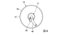
端管23には、その外周部の前後にベアリング45,46が設けられており、これらベアリング45,46はスピンノズル17を回転可能に支持している。つまり、スピンノズル17は端管23に回転可能に支持されている。スピンノズル17は、ベアリング45,46のアウタレースに内周面が嵌合固定される金属製の円筒体47と、円筒体47の端部に固定される金属製の環状体48と、環状体48の内周部に固定され、端管23の前方にて斜め前方に延出する金属製のノズル本体49とを有している。スピンノズル17は、長配管21、短配管22および端管23を介して導入される圧縮気体をノズル本体49から外部に放出することになり、その際に、放出反力がスピンノズル17に回転力を生じさせるように、ノズル本体49が図4に示すように曲げられている。図3に示すスピンノズル17は、ベアリング45,46のアウタレースと一体に回転する。ノズル本体49には、スピンノズル17が回転する際に生じる振動を抑制するバランサ50がノズル本体49の長さ方向および周方向に位置調整可能となるように取り付けられている。
The
カバー18は、端管23におけるスピンノズル17と短配管22の連結部材41との間に嵌合される合成ゴム製の嵌合部材54と、嵌合部材54の外周部に接合されてスピンノズル17を覆う透明な合成樹脂製のカバー本体55とを有している。カバー本体55は、嵌合部材54に後端が接合されて円筒体47と同軸状に配置される円筒部56と、円筒部56の前端から前方ほど径が大きくなるように拡径する錐形筒部57とを有している。
The
第1実施形態に係る掘削ガン10は、図2に示すように、分岐部材15の側部連結部33に、分岐部材15から側方に突出した後に下側に延出するように液体供給切替部60が連結されている。この液体供給切替部60は、分岐部材15の側部連結部33に螺合により連結され側部連結部33から導入される圧縮空気で作動する上部の作動部61と、作動部61の下部に前後方向に延在して設けられ前部連結部62と後部連結部63との連通・遮断を切り替える切替部64とを有している。後部連結部63は、後方に向け開口しており、この後部連結部63には、下方に開口する下部連結部66を有する連結部材67が螺合により連結されている。
As shown in FIG. 2, the
連結部材67の下部連結部66には、ツマミ68の手動操作量に応じて流路面積を全閉から全開まで無段階で変更する流量調整弁69が上端部において連結されている。流量調整弁69は、分岐部材15から液体供給切替部60が突出する側方とは反対の側方にツマミ68を突出させる姿勢で連結部材67に取り付けられている。この流量調整弁69の下部には、図1に示すように加圧液体供給源であるウォータポンプ71に接続される接続部材(液体供給源接続部)72が連結されている。よって、液体供給切替部60は、作動部61が分岐部材15から導入された圧縮気体の圧力により作動して切替部64を駆動し、接続部材72に導入される加圧液体の前部連結部62への供給・停止を切り替える。ウォータポンプ71は、エアコンプレッサ26から供給される圧縮気体によって駆動されて、タンク73に貯留された水を吸引し加圧して吐出するものである。勿論、電動で水を吸引し加圧して吐出するウォータポンプを用いてもよい。
A flow
液体供給切替部60の前部連結部62には、液体配管75の一端が連結されており、液体配管75の他端は短配管22の下端部の連結部材41の後部連結部42に連結されている。つまり、液体配管75は、液体供給切替部60から前方に延出して短配管22の下端部に連結される。液体配管75は、液体供給切替部60の前部連結部62に螺合により連結される金属製の連結部材76と、短配管22の連結部材41の後部連結部42に螺合により連結される金属製の連結部材77と、これら連結部材76,77同士を結ぶ合成樹脂製の可撓性のチューブ78とを有している。なお、上記した流量調整弁69を、上記のように接続部材72と液体供給切替部60との間に設けるのではなく、液体配管75に設けても良い。
One end of the
図3に示すように、液体配管75の連結部材77には、金属製の内管80が一端側において固定されており、この内管80は、短配管22の連結部材41内を通り、端管23内で前方に延出する。内管80は、先端がスピンノズル17のノズル本体49内に配置されており、液体配管75から導入された液体をスピンノズル17のノズル本体49内に放出する。
As shown in FIG. 3, a metal
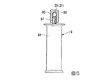
図5に示すように、スライドグリップ19は、長配管21の配管本体35に沿ってスライド可能かつ配管本体35を中心に回転可能となるように配管本体35に取り付けられている。スライドグリップ19は、配管本体35を嵌合させる嵌合穴85が形成されたベース部材86と、このベース部材86に螺合されるネジ軸部87を有するグリップ本体88とからなっている。グリップ本体88のネジ軸部87は嵌合穴85に対し進退可能であり、よって嵌合穴85内の配管本体35に対し進退可能となっている。つまり、スライドグリップ19は、グリップ本体88のネジ軸部87が、ベース部材86に対し緩められて配管本体35から離れた状態では配管本体35上をスライド可能かつ配管本体35を中心に回転可能であり、ベース部材86に締め込まれて配管本体35に当接すると、配管本体35に対し固定される。図1に示すように、スライドグリップ19と液体配管75のチューブ78とには、環状部材90が巻かれており、これによりチューブ78をスライドグリップ19に対し拘束してその不要な変位を規制している。
As shown in FIG. 5, the
以上に述べた第1実施形態の掘削ガン10を用いて地面を掘削する場合、作業者は、掘削ガン10の接続部材27にエアコンプレッサ26を接続し、接続部材72にウォータポンプ71を接続する。この状態で、作業者が、ガン本体14のグリップ部12を一方の手で握るとともに適宜の位置に固定されたスライドグリップ19を他方の手で握って、グリップ部12の前側に並設されているレバー25を一方の手の指で手前に引くと、気体供給切替部30が、接続部材27に導入されている圧縮空気を分岐部材15に流す状態となる。すると、分岐部材15から一方に流れる圧縮空気が、分岐部材15の前部から前方に延出する長配管21、長配管21の前端部から下方に延出する短配管22および短配管22の下端部から前方に延出する端管23を通って、スピンノズル17から放出される。その際に、スピンノズル17は放出反力で回転することになる。また、分岐部材15から他方に流れる圧縮空気は、液体供給切替部60に導入されることになり、その結果、液体供給切替部60が接続部材72に加圧状態で導入されている水を液体配管75に供給する状態になる。液体配管75に供給された水は、端管23内で前方に延出する内管80を通ってスピンノズル17のノズル本体49内に放出されることになり、上記した圧縮空気と混合されて、回転するスピンノズル17のノズル本体49から噴出する。そして、作業者は、このように旋回するスピンノズル17の先端から噴出するエアと水の気液混合流体で掘削を行うことになる。
When excavating the ground using the
上記のような手持ち操作可能な掘削ガン10を用いることにより、気液混合流体の噴出位置や噴出方向を容易に調整することができるため、地下埋設物が密集している場合であっても容易に地面の掘削作業を行うことができる。また、気液混合流体で掘削を行うことになるため、液体である水の使用量を抑えることができる。加えて、圧縮空気をスピンノズル17に流すための配管において、分岐部材15から前方に延出する長配管21の前端部から短配管22を下方に延出させ、この短配管22の下端部から前方に端管23を延出させており、水をスピンノズル17に流すための配管において、液体供給切替部60を分岐部材15の下側に延出させて、液体供給切替部60と短配管22の下端部とを結んで液体配管75を配置している。このため、気体および液体をスピンノズル17に流すための配管全体の幅を抑えてコンパクト化することができる。よって、掘削作業の作業性を向上させることができる。
By using the
また、スライドグリップ19が長配管21の配管本体35にスライド可能に取り付けられているため、スライドグリップ19の位置調整が可能となる。よって、掘削作業の作業性をさらに向上させることができる。また、スライドグリップ19が長配管21の配管本体35をスライドするため、スライドグリップ19のスライドを案内するための専用の部品が不要になり、部品点数およびコストを低減することができる。
Further, since the
次に、本発明の第2実施形態に係る掘削ガンを図6を参照して第1実施形態との相違部分を中心に説明する。 Next, an excavation gun according to a second embodiment of the present invention will be described with reference to FIG. 6 focusing on the differences from the first embodiment.
第2実施形態においては、第1実施形態の端管23とは異なる端管93が、短配管22の下端部となる連結部材41の前部連結部43に連結されている。端管93は、短配管22の下端部から前方に延出しており、短配管22の連結部材41の前部連結部43に螺合により連結されて前方に延出する小径管95と、小径管95の前端部に螺合により連結されて前方に延出する小径管95より大径の大径管96と、大径管96の前端部に螺合により連結される蓋部材97とからなっている。そして、スピンノズル98が、先端側が曲げられた一つの金属製の管材からなっており、このスピンノズル98の基端側の直線部分に前後に離間してベアリング99,100が取り付けられている。これらベアリング99,100が端管93の大径管96の内周面に支持されている。なお、蓋部材97は、ベアリング99に当接することでスピンノズル98が端管93から抜け出すことを規制している。
In the second embodiment, an
以上により、第2実施形態においては、スピンノズル98が、端管93の大径管96の内周面にベアリング99,100を介して回転可能に支持されており、ベアリング99,100のインナレースと一体に回転する。スピンノズル98も、長配管21、短配管22および端管93を介して導入される圧縮気体を外部に放出することになり、その際に、放出反力が回転力を生じるように曲げられている。
As described above, in the second embodiment, the
以上に述べた第2実施形態によれば、スピンノズル98が、端管93の内周面にベアリング99,100を介して回転可能に支持されているため、スピンノズル98とともに回転する部品がベアリング99,100のインナレースとなり、回転部品の重量を抑えることができる。したがって、スピンノズル17がより高速で回転可能となる。
According to the second embodiment described above, since the
なお、第2実施形態において、ベアリング99,100をメンテナンスする必要が生じた場合には、端管93の蓋部材97を、螺合を解除することにより大径管96から取り外して、大径管96からスピンノズル98を抜けば、スピンノズル98とともにベアリング99,100が大径管96から抜き出されることになる。したがって、ベアリング99,100のメンテナンスが容易となる。
In the second embodiment, when the
10 掘削ガン
12 グリップ部
15 分岐部材(分岐部)
17,98 スピンノズル
19 スライドグリップ
21 長配管(前方延出配管)
22 短配管(下方延出配管)
23,93 端管
25 レバー
26 エアコンプレッサ(圧縮気体供給源)
27 接続部材(気体供給源接続部)
30 気体供給切替部
45,46,99,100 ベアリング
60 液体供給切替部
71 ウォータポンプ(加圧液体供給源)
72 接続部材(液体供給源接続部)
75 液体配管
80 内管
10
17,98
22 Short piping (downward extending piping)
23, 93
27 Connection member (gas supply source connection)
30 Gas
72 Connection member (liquid supply source connection)
75
Claims (3)
該グリップ部の前側に並設されるレバーと、
圧縮気体供給源に接続される気体供給源接続部と、
加圧液体供給源に接続される液体供給源接続部と、
前記気体供給源接続部に導入される圧縮気体の供給・停止を前記レバーの操作により切り替える気体供給切替部と、
該気体供給切替部からの圧縮気体の供給先を二方向とする分岐部と、
該分岐部から下側に延出し該分岐部から導入された圧縮気体により前記液体供給源接続部に導入される加圧液体の供給・停止を切り替える液体供給切替部と、
前記分岐部の前部に連結されて該分岐部から前方に延出する前方延出配管と、
該前方延出配管の前端部に連結されて下方に延出する下方延出配管と、
該下方延出配管の下端部に連結されて前方に延出する端管と、
該端管に回転可能に支持され前記前方延出配管、前記下方延出配管および前記端管を介して導入される圧縮気体を放出するとともに放出反力で回転するスピンノズルと、
前記液体供給切替部から前方に延出し前記下方延出配管の下端部に連結される液体配管と、
該液体配管に連結され前記端管内で前方に延出して液体を前記スピンノズル内に放出する内管と、
を有することを特徴とする掘削ガン。 A grip part;
A lever arranged side by side on the front side of the grip part;
A gas source connection connected to the compressed gas source;
A liquid source connection connected to the pressurized liquid source;
A gas supply switching unit that switches supply / stop of compressed gas introduced into the gas supply source connection unit by operating the lever;
A bifurcation unit having two directions as the supply destination of the compressed gas from the gas supply switching unit;
A liquid supply switching unit that switches the supply / stop of pressurized liquid introduced into the liquid supply source connection unit by the compressed gas that extends downward from the branch unit and is introduced from the branch unit;
A front extension pipe connected to the front part of the branch part and extending forward from the branch part;
A lower extension pipe connected to the front end of the front extension pipe and extending downward;
An end pipe connected to the lower end of the downward extending pipe and extending forward;
A spin nozzle that is rotatably supported by the end pipe and releases the compressed gas introduced through the front extension pipe, the lower extension pipe and the end pipe, and rotates by a discharge reaction force;
A liquid pipe extending forward from the liquid supply switching section and connected to a lower end of the downward extending pipe;
An inner pipe connected to the liquid pipe and extending forward in the end pipe to discharge the liquid into the spin nozzle;
An excavation gun comprising:
Priority Applications (1)
| Application Number | Priority Date | Filing Date | Title |
|---|---|---|---|
| JP2013082948A JP6080664B2 (en) | 2013-04-11 | 2013-04-11 | Drilling gun |
Applications Claiming Priority (1)
| Application Number | Priority Date | Filing Date | Title |
|---|---|---|---|
| JP2013082948A JP6080664B2 (en) | 2013-04-11 | 2013-04-11 | Drilling gun |
Publications (2)
| Publication Number | Publication Date |
|---|---|
| JP2014205973A JP2014205973A (en) | 2014-10-30 |
| JP6080664B2 true JP6080664B2 (en) | 2017-02-15 |
Family
ID=52119746
Family Applications (1)
| Application Number | Title | Priority Date | Filing Date |
|---|---|---|---|
| JP2013082948A Active JP6080664B2 (en) | 2013-04-11 | 2013-04-11 | Drilling gun |
Country Status (1)
| Country | Link |
|---|---|
| JP (1) | JP6080664B2 (en) |
Families Citing this family (1)
| Publication number | Priority date | Publication date | Assignee | Title |
|---|---|---|---|---|
| JP2020089844A (en) * | 2018-12-06 | 2020-06-11 | 有限会社ガリュー | Revolving nozzle |
Family Cites Families (7)
| Publication number | Priority date | Publication date | Assignee | Title |
|---|---|---|---|---|
| DE3141583C2 (en) * | 1981-10-20 | 1983-11-03 | Lars Anders 41319 Göteborg Molinder | Underwater cutting tool |
| NL9001359A (en) * | 1990-06-15 | 1992-01-02 | Philips Nv | ELECTRONIC DEVICE FOR RECEIVING A MODULATED CARRIER SIGNAL. |
| JPH05131399A (en) * | 1991-11-06 | 1993-05-28 | Atsushi Kurosawa | Cutting and cutting-off by jet |
| JP3828693B2 (en) * | 1999-11-09 | 2006-10-04 | 兼松エンジニアリング株式会社 | Nozzle for underground excavation and underground excavator for installing electric pole using this nozzle |
| US6691436B2 (en) * | 2001-06-28 | 2004-02-17 | Franklin J. Chizek, Sr. | Hand-held device for exposing buried objects |
| JP2004276187A (en) * | 2003-03-17 | 2004-10-07 | Sugino Mach Ltd | Water jet injection apparatus |
| WO2009004744A1 (en) * | 2007-07-04 | 2009-01-08 | Ga-Rew Corporation | Fluid jet gun |
-
2013
- 2013-04-11 JP JP2013082948A patent/JP6080664B2/en active Active
Also Published As
| Publication number | Publication date |
|---|---|
| JP2014205973A (en) | 2014-10-30 |
Similar Documents
| Publication | Publication Date | Title |
|---|---|---|
| JP5020320B2 (en) | Fluid ejection gun | |
| US8444068B2 (en) | Dual flow pressure washer | |
| US7854398B2 (en) | Hand held pressure washer | |
| US20150174598A1 (en) | Spray gun for use with a pressure washer | |
| US8719997B1 (en) | Pass-through vacuum | |
| US20060289036A1 (en) | Gutter cleaning device | |
| JP6080664B2 (en) | Drilling gun | |
| US7341504B1 (en) | Adjustable sand blasting gun | |
| JP2011169461A5 (en) | ||
| US10076760B2 (en) | Pneumatically powered foam sprayer | |
| JP2014014777A (en) | Water jet system | |
| EP2497578A3 (en) | Remediation of underwater fluid storage tanks | |
| US982023A (en) | Pipe-laying mechanism. | |
| JP2019212996A5 (en) | ||
| CA2394643A1 (en) | Device for hydraulic power supply of a rotary apparatus for percussive drilling | |
| CN104145081A (en) | Roof bolter | |
| US20080054104A1 (en) | Compressed air guns, handpieces, and nozzles | |
| JP2004290716A (en) | Method for discharging impurities in pipe and discharge appliance | |
| US671774A (en) | Sand-blasting device. | |
| US20170028423A1 (en) | Shield apparatus for a blowgun | |
| JP5914118B2 (en) | Pipe air discharge method | |
| JP5963820B2 (en) | Static elimination dust removal equipment that does not require external power supply | |
| CN201604079U (en) | Handheld air spot sand blaster | |
| CN209259153U (en) | A kind of multisection type connecting rod feeding mechanism | |
| JPS5935277B2 (en) | Rehabilitation method and device for old pipes |
Legal Events
| Date | Code | Title | Description |
|---|---|---|---|
| A621 | Written request for application examination |
Free format text: JAPANESE INTERMEDIATE CODE: A621 Effective date: 20160316 |
|
| A977 | Report on retrieval |
Free format text: JAPANESE INTERMEDIATE CODE: A971007 Effective date: 20161207 |
|
| TRDD | Decision of grant or rejection written | ||
| A01 | Written decision to grant a patent or to grant a registration (utility model) |
Free format text: JAPANESE INTERMEDIATE CODE: A01 Effective date: 20161220 |
|
| A61 | First payment of annual fees (during grant procedure) |
Free format text: JAPANESE INTERMEDIATE CODE: A61 Effective date: 20170117 |
|
| R150 | Certificate of patent or registration of utility model |
Ref document number: 6080664 Country of ref document: JP Free format text: JAPANESE INTERMEDIATE CODE: R150 |
|
| R250 | Receipt of annual fees |
Free format text: JAPANESE INTERMEDIATE CODE: R250 |
|
| R250 | Receipt of annual fees |
Free format text: JAPANESE INTERMEDIATE CODE: R250 |
|
| R250 | Receipt of annual fees |
Free format text: JAPANESE INTERMEDIATE CODE: R250 |
|
| R250 | Receipt of annual fees |
Free format text: JAPANESE INTERMEDIATE CODE: R250 |
|
| R250 | Receipt of annual fees |
Free format text: JAPANESE INTERMEDIATE CODE: R250 |