JP6080503B2 - Image processing device - Google Patents
Image processing device Download PDFInfo
- Publication number
- JP6080503B2 JP6080503B2 JP2012244601A JP2012244601A JP6080503B2 JP 6080503 B2 JP6080503 B2 JP 6080503B2 JP 2012244601 A JP2012244601 A JP 2012244601A JP 2012244601 A JP2012244601 A JP 2012244601A JP 6080503 B2 JP6080503 B2 JP 6080503B2
- Authority
- JP
- Japan
- Prior art keywords
- image
- positional deviation
- ratio
- images
- input
- Prior art date
- Legal status (The legal status is an assumption and is not a legal conclusion. Google has not performed a legal analysis and makes no representation as to the accuracy of the status listed.)
- Active
Links
- 239000000203 mixture Substances 0.000 claims description 40
- 238000000034 method Methods 0.000 claims description 30
- 238000001514 detection method Methods 0.000 claims description 23
- 230000015572 biosynthetic process Effects 0.000 claims description 12
- 238000003786 synthesis reaction Methods 0.000 claims description 12
- 239000002131 composite material Substances 0.000 claims description 9
- 230000009466 transformation Effects 0.000 claims description 9
- 230000002194 synthesizing effect Effects 0.000 claims 2
- 238000003672 processing method Methods 0.000 claims 1
- 239000013598 vector Substances 0.000 description 16
- 238000006243 chemical reaction Methods 0.000 description 11
- 238000003384 imaging method Methods 0.000 description 11
- 230000006870 function Effects 0.000 description 9
- 238000010586 diagram Methods 0.000 description 4
- 238000000605 extraction Methods 0.000 description 4
- 208000003443 Unconsciousness Diseases 0.000 description 3
- 238000006073 displacement reaction Methods 0.000 description 3
- 238000011156 evaluation Methods 0.000 description 2
- PXFBZOLANLWPMH-UHFFFAOYSA-N 16-Epiaffinine Natural products C1C(C2=CC=CC=C2N2)=C2C(=O)CC2C(=CC)CN(C)C1C2CO PXFBZOLANLWPMH-UHFFFAOYSA-N 0.000 description 1
- 238000004364 calculation method Methods 0.000 description 1
- 230000007423 decrease Effects 0.000 description 1
- 230000000694 effects Effects 0.000 description 1
- 230000007717 exclusion Effects 0.000 description 1
- 239000004973 liquid crystal related substance Substances 0.000 description 1
- 230000003287 optical effect Effects 0.000 description 1
- 230000011218 segmentation Effects 0.000 description 1
- 239000004065 semiconductor Substances 0.000 description 1
- 230000035945 sensitivity Effects 0.000 description 1
Images


Description
本発明は、複数の画像データを合成して、画像データのダイナミックレンジを拡大する画像処理装置に関する。 The present invention relates to an image processing apparatus that combines a plurality of image data to expand the dynamic range of the image data.
従来より、露出の異なる複数の画像を合成することにより、ダイナミックレンジが拡大された合成画像を得る処理が提案されている。前記処理は、低輝度領域に対しては高露出画像を主に使用し、高輝度領域に対しては低露出画像を主に使用することで、白とび、黒潰れの影響を低減し、画像のダイナミックレンジを拡大するものである。 Conventionally, a process for obtaining a composite image with an expanded dynamic range by combining a plurality of images with different exposures has been proposed. The processing mainly uses high-exposure images for low-brightness areas, and mainly uses low-exposure images for high-brightness areas, thereby reducing the effects of overexposure and blackout, It expands the dynamic range.
前記処理において、複数撮影されたそれぞれの画像データは、手ぶれ等により相対的な位置ズレが発生しているため、合成の前に位置ズレを補正する処理が必須となる。合成の際に、画像データ間に位置ズレが発生している場合、合成画像において像が多重に写り、合成画像の画質が低下する。従って、複数撮影された画像データの位置合わせは重要な技術となる。 In the above-described processing, each of a plurality of captured image data has a relative positional shift due to camera shake or the like, and therefore a process for correcting the positional shift before combining is essential. If a positional shift occurs between the image data at the time of combining, the images are duplicated in the combined image, and the image quality of the combined image is deteriorated. Therefore, alignment of a plurality of captured image data is an important technique.
上述した画像データの位置合わせ技術に関しては、例えば特許文献1においては、画像間の位置ズレ量を求める際に、それぞれの画像の共通輝度領域のみを使用して位置ズレ検出を行い、位置合わせを行う技術が提案されている。
With regard to the above-described image data alignment technique, for example, in
また、特許文献2においては、動きベクトルの誤検出の要因となる低コントラスト領域の除外を行う。さらに前記除外処理において動き検出に適当と判断された小領域毎の動きベクトルの分布を見て、画像全体の動きを的確に表していると判断された動きベクトルのみを採用して位置合わせを行う技術が提案されている。
In
しかしながら、特許文献1、および特許文献2においては、被写体の微小な動きや、被写体の距離差による動きの違いにより、位置合わせで補正しきれず位置ズレが残留することが予想される。
However, in
また、見かけ上のダイナミックレンジ拡大を目的とした画像合成では、低輝度領域においては高露出画像の合成比率を高く設定し、高輝度領域においては低露出画像の合成比率を高く設定する。さらに、合成画像に生じる急な切り替わりを防ぐために、中間輝度領域では高露出画像と低露出画像を加重加算するように合成比率を設定する。 Also, in image synthesis for the purpose of apparent dynamic range expansion, a high exposure image synthesis ratio is set high in the low luminance region, and a low exposure image synthesis ratio is set high in the high luminance region. Further, in order to prevent a sudden change occurring in the composite image, the composite ratio is set so that the high-exposure image and the low-exposure image are weighted and added in the intermediate luminance region.
従って、高露出画像と低露出画像を加重加算する領域において位置ズレが残留している場合には、合成の際に前記位置ズレが目立って見えてしまい、合成画像の画質が劣化するという課題がある。 Therefore, when a positional deviation remains in an area where the high-exposure image and the low-exposure image are weighted and added, the positional deviation becomes noticeable at the time of synthesis, and the image quality of the synthesized image deteriorates. is there.
本発明は、上記の問題点に鑑み、画像データを加重加算する領域に発生する位置ズレの低減を目的とする。 In view of the above problems, an object of the present invention is to reduce a positional shift that occurs in an area where image data is weighted and added.
前記目的を達成するために、本発明の画像処理装置は以下の構成を備える。 In order to achieve the above object, an image processing apparatus of the present invention comprises the following arrangement.
少なくとも2枚以上の画像を入力する画像入力手段と、
前記入力画像間の位置ズレ量を検出する位置ズレ量検出手段と、
検出された前記位置ズレ量から、前記位置ズレを補正するための座標変換係数を算出し、前記入力画像に前記座標変換係数を用いて座標変換を施すことで、前記入力画像間の位置ズレを補正する位置ズレ補正手段と、
前記位置ズレが補正された入力画像から、位置ズレが残留している領域を検出する位置ズレ残留領域検出手段と、
前記入力画像の合成比率を所定の領域毎に設定する合成比率設定手段と、
前記位置ズレが補正された入力画像を前記設定された合成比率に基づいて合成する画像合成手段を備える。
Image input means for inputting at least two or more images;
A positional deviation amount detecting means for detecting a positional deviation amount between the input images;
A coordinate transformation coefficient for correcting the positional deviation is calculated from the detected positional deviation amount, and coordinate transformation is performed on the input image using the coordinate transformation coefficient, thereby correcting the positional deviation between the input images. Position misalignment correcting means for correcting;
A positional deviation residual area detecting means for detecting an area where the positional deviation remains from an input image in which the positional deviation is corrected;
A composition ratio setting means for setting a composition ratio of the input image for each predetermined region;
Image compositing means for compositing the input image in which the positional deviation is corrected based on the set compositing ratio.
本発明によれば、複数の画像データを合成する場合において、画像データを加重加算する領域で発生する位置ズレを低減することが出来る。 According to the present invention, when combining a plurality of image data, it is possible to reduce a positional shift that occurs in an area where the image data is weighted and added.
[第1の実施形態]
以下、図面を参照して、本発明の第1の実施形態について詳細に説明する。
[First Embodiment]
Hereinafter, a first embodiment of the present invention will be described in detail with reference to the drawings.
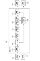
図1は、本発明の第1の実施形態の画像処理装置に適用可能な構成を示したブロック図である。なお、本実施例は、画像データのダイナミックレンジを拡大する撮像装置である。 FIG. 1 is a block diagram showing a configuration applicable to the image processing apparatus according to the first embodiment of the present invention. The present embodiment is an imaging apparatus that expands the dynamic range of image data.
撮像部101は、撮像レンズ群とCMOSやCCD等の半導体撮像素子からなる。撮像部101(画像取得手段)において、同一被写体に対して露出条件を変化させながら少なくとも2枚以上の入力画像を取得するために複数回の撮影が行われ、撮影された映像信号はA/D変換部102に出力される。露出条件としては、露光時間(シャッター速度)、絞り値(F値)、ISO感度などで制御することができ、不図示の測光センサや撮像部101より前回取得された画像から得られる明るさの情報に基づいて各パラメータが制御される。A/D変換部102は、入力された映像信号をデジタル画像データに変換し、画像処理部103に出力する。画像処理部103は、入力された複数の画像データの位置ズレを補正し、前記位置ズレが補正された画像データの合成処理を行う。画像表示部111は、画像処理部103で生成された画像データを、例えば、撮像装置本体が備える液晶モニタに表示する。さらに、画像記憶部112は、画像処理部103で生成された画像データを、記録媒体へ記録する。
The
次に、画像処理部103について、詳細な説明を行う。画像処理部103は、階調補正部104、メモリ部105、位置ズレ検出部106(位置ズレ量検出手段)、位置ズレ補正部107、位置ズレ残留領域検出部108、合成比率設定部109、画像合成部110により構成されている。
Next, the
階調補正部104は、入力された複数の画像データに対して、輝度レベルを合わせる処理を行う。ここでは、入力画像データの枚数を2枚と仮定し、露出条件の異なる入力画像データに対して、相対的に露出の大きい画像をオーバー画像、オーバー画像に対して露出の小さい画像をアンダー画像とする。階調補正部104において、オーバー画像とアンダー画像のそれぞれに対し、図2に示すような、異なる階調変換特性を持った階調変換を施すことで、オーバー画像とアンダー画像の輝度レベルを合わせる。ただし、本実施例では、アンダー画像の輝度レベルをオーバー画像に合わせている。階調補正部104で処理された画像データは、メモリ部105に蓄えられる。
The
メモリ部105に蓄えられた画像データは、手ぶれ等に因る相対的な位置のずれを伴っている。そのため、位置ズレ検出部106、および位置ズレ補正部107によって、画像データ間の位置ズレを補正する。各部の詳細な処理は後述する。
The image data stored in the
<位置ズレ検出部106>
図3は、位置ズレ検出部106における入力画像間の位置ズレ量を検出する処理の流れを示すフローチャートである。図3に示すように、ステップS301において入力された画像データに対し、ステップS302において、位置ズレを求める基準となる、基準画像を設定する。ここでは、アンダー画像を基準画像に設定する。すなわち、本実施例における位置ズレとは、アンダー画像に対する、オーバー画像の位置ズレを意味する。
<Position
FIG. 3 is a flowchart showing a flow of processing for detecting a positional shift amount between input images in the positional
次に、ステップS303において、図4に示すように、画像データを水平方向にN分割、垂直方向にM分割した複数のブロックに分割する。ここで、今後の処理の説明のために、各分割ブロックをblk[0]〜blk[M*N−1]と呼ぶ。続いて、ステップS304においてカウンターiの値にi=0を設定し、ステップS305において、i番目の分割ブロックblk[i]について、アンダー画像とオーバー画像間の相対的な位置ズレ量を表す動きベクトルを検出する。動きベクトルの検出方法としては、例えば、差分絶対値和を評価値としたパターンマッチング処理が提案されている。さらに、ステップS306およびS307において、iをインクリメントしながら全分割ブロックにおける動きベクトルを算出する。 Next, in step S303, as shown in FIG. 4, the image data is divided into a plurality of blocks that are divided into N parts in the horizontal direction and M parts in the vertical direction. Here, for description of future processing, each divided block is referred to as blk [0] to blk [M * N-1]. Subsequently, in step S304, i = 0 is set as the value of the counter i, and in step S305, a motion vector representing a relative positional shift amount between the under image and the over image for the i-th divided block blk [i]. Is detected. As a motion vector detection method, for example, a pattern matching process using a sum of absolute differences as an evaluation value has been proposed. Further, in steps S306 and S307, motion vectors in all the divided blocks are calculated while i is incremented.
<位置ズレ補正部107>
図5は、位置ズレ補正部107における処理の流れを示すフローチャートである。図5に示すように、ステップS501において入力された各分割ブロックにおける動きベクトル全体に対し、ステップS502において信頼度の高い動きベクトルのみを抽出する。ここで述べる信頼度とは、手振れによる主要被写体の動きを表す度合いを意味する。
<Position
FIG. 5 is a flowchart showing the flow of processing in the positional
前記抽出の方法としては、例えば、各分割ブロック内の白とび、黒潰れ画素の割合や、エッジ積分値を評価値として抽出を行う方法が挙げられる。これは、パターンマッチングによる動きベクトル誤検出の影響を低減することが目的である(特開2008−118555号公報)。また、その他の抽出方法としては、動きベクトルの分布をとり、主要被写体の動きベクトルと近い値を持つ動きベクトルのみを抽出する方法が挙げられる。これは、同じ手振れに対する動きでも、主要被写体と背景で距離が大きく異なる場合に、動き量に差異が出るため、主要被写体の動きベクトルを正確に抽出すること、および誤検出による異端な動きベクトルを排除することを目的としている。 Examples of the extraction method include a method of performing extraction using the ratio of overexposed and black-out pixels in each divided block and the edge integral value as an evaluation value. The purpose of this is to reduce the influence of erroneous detection of motion vectors by pattern matching (Japanese Patent Laid-Open No. 2008-118555). As another extraction method, there is a method of taking a motion vector distribution and extracting only a motion vector having a value close to the motion vector of the main subject. This is because even if the movement is the same for the same camera shake, if the distance between the main subject and the background is significantly different, the amount of movement will be different. The purpose is to eliminate.
前述した信頼度の高い動きベクトルの抽出方法に関しては、あくまで一例であって、ここでは特に限定されないものとする。 The above-described highly reliable motion vector extraction method is merely an example, and is not particularly limited here.
次に、ステップS503において、前述のステップS502から出力された高信頼度の動きベクトルを入力として、位置ズレ補正パラメータの推定を行う。位置ズレ補正パラメータとは、一方の画像をもう一方の画像に合わせて変形するための座標変換係数のことで、例えば、アフィン変換係数、射影変換係数などが挙げられる。また、画像変換係数を算出する手法としては、複数の動きベクトルを入力し、入力された動きベクトルから、最小二乗法により画像変換係数の推定を行うという手法が提案されている。 Next, in step S503, the positional deviation correction parameter is estimated using the highly reliable motion vector output from step S502 described above as an input. The misregistration correction parameter is a coordinate conversion coefficient for deforming one image in accordance with the other image, and includes, for example, an affine conversion coefficient and a projective conversion coefficient. As a method for calculating an image conversion coefficient, a method has been proposed in which a plurality of motion vectors are input, and the image conversion coefficient is estimated from the input motion vectors by a least square method.
次に、ステップS504によって、ステップS503で推定した画像変換係数を用いて、オーバー画像の変形を行う。 Next, in step S504, the over image is deformed using the image conversion coefficient estimated in step S503.
上記一連の処理により、アンダー画像(基準画像)に位置が合った、オーバー画像が生成される。 Through the series of processes, an over image is generated that is aligned with the under image (reference image).
<位置ズレ残留領域検出部108>
位置ズレ残留領域検出部108では、位置ズレ補正部107で位置ズレの補正を行ったアンダー画像とオーバー画像を入力とし、前記2画像において位置ズレが残留している領域を検出する。ここで、位置ズレが残留する原因としては、前述のように被写体と背景の距離差による動き量の差異や、被写体自身の微小な動きが補正しきれずに残留することが挙げられる。
<Position displacement residual
The misregistration residual
位置ズレ残留領域の検出方法の模式図を図6に示す。図6に示すように、位置ズレ補正を行ったアンダー画像とオーバー画像の差分をとり、差分画像を生成する。ここでの差分は、輝度差分の絶対値を想定しているが、背景と主要被写体の輝度が等しい場合には検出精度が低下するので、併せて色差信号の差分を使用してもよい。前記差分画像において差分が生じた領域が位置ズレ残留領域となる。また、白とび、黒潰れを起こしている領域については、位置ズレの残留を起因としない差分が検出されるため、予め検出対象領域から除外しておくなどの工夫が必要である。また位置ズレ残留領域検出の手法としては、上記に限らず、2画像の相関を取り、その相関の高さを領域毎に評価できる演算方法であればいずれを用いても良い。 FIG. 6 shows a schematic diagram of a method for detecting a misregistration residual area. As shown in FIG. 6, a difference image is generated by taking the difference between the under image and the over image that have been subjected to positional deviation correction. The difference here is assumed to be the absolute value of the luminance difference. However, if the luminance of the background and the main subject are equal, the detection accuracy decreases, and therefore the difference of the color difference signal may be used together. A region where a difference occurs in the difference image is a misalignment remaining region. Further, since a difference that is not caused by a residual positional deviation is detected in a region where overexposure or blackout occurs, it is necessary to devise a method such as excluding from the detection target region in advance. The method for detecting the misaligned residual region is not limited to the above, and any calculation method can be used as long as it can correlate two images and evaluate the height of the correlation for each region.
<合成比率設定部109>
図7は、合成比率設定部109における処理の流れを示すフローチャートである。図7に示すように、まずステップS701において、基準輝度画像の設定を行う。基準輝度画像とは、入力画像データの合成比率を設定するために参照する輝度画像である。ここでは、基準輝度画像としてアンダー画像の輝度成分を使用するが、基準輝度画像として、オーバー画像を使用してもよい。
<Composition
FIG. 7 is a flowchart showing the flow of processing in the composition
次に、ステップS702に示すように、基準輝度画像の画素値から、合成比率テーブルに基づいて、各画素におけるアンダー画像とオーバー画像の合成比率を設定する。合成比率テーブルとは、基準となる輝度値に対して、アンダー画像とオーバー画像の合成比率を設定するテーブルである。図8に、本実施例における合成比率テーブルを示した。ここでは、図8に示すように、基準輝度の値をYとした時、Y≦Y1の領域では、オーバー画像を100%使用し、Y2≦Yの領域では、アンダー画像を100%使用する。さらにY1<Y<Y2の領域では、アンダー画像とオーバー画像を加重加算するように、合成比率テーブルを設定している。ここで、Y1,Y2は、予め設定された輝度値である。 Next, as shown in step S702, based on the pixel value of the reference luminance image, the composition ratio of the under image and the over image in each pixel is set based on the composition ratio table. The composition ratio table is a table for setting the composition ratio of the under image and the over image with respect to the reference luminance value. FIG. 8 shows a synthesis ratio table in the present embodiment. Here, as shown in FIG. 8, when the reference luminance value is Y, 100% of the over image is used in the region of Y ≦ Y1, and 100% of the under image is used in the region of Y2 ≦ Y. Further, in the region of Y1 <Y <Y2, the composition ratio table is set so that the under image and the over image are weighted and added. Here, Y1 and Y2 are preset brightness values.
ここで、本件で課題としている、残留した位置ズレが顕在化する(多重に分裂して写る)領域は、オーバー画像とアンダー画像を加重加算する輝度を持つ領域において、位置ズレが残留していた場合に発生する。従って、前記位置ズレが顕在化する領域を検出し、該当領域においてはアンダー画像が100%出力されるように合成比率を制御することで、残留した位置ズレの顕在化を低減することができる。ここで、アンダー画像を100%出力するように制御を行う理由としては、本実施例ではアンダー画像が位置合わせの基準画像であることと、100%出力される領域の白とびを避けるためである。
Here, in the area where the residual positional deviation that appears as a problem in this case becomes apparent (divided in multiple divisions), the positional deviation remains in the area that has the luminance for weighted addition of the over image and the under image. Occurs when. Therefore, by detecting a region where the positional deviation becomes apparent and controlling the composition ratio so that an under image is
上記背景を踏まえ、次に、ステップS703に示すように、加重加算領域かつ位置ズレ残留領域の検出を行う。ここで、加重加算領域とは、前述のステップS702において、アンダー画像とオーバー画像がどちらか一方の画像のみを使用するような合成比率(100:0あるいは0:100[%])でない、少なくとも2枚の画像が合成される加重加算を示す領域であるとする。ただし、加重加算領域の定義はこれに限定されるものではなく、例えば、加重加算係数の範囲で決定してもよい。 Based on the above background, next, as shown in step S703, a weighted addition region and a misaligned residual region are detected. Here, the weighted addition area is at least 2 which is not a composition ratio (100: 0 or 0: 100 [%]) in which only one of the under image and the over image is used in step S702 described above. It is assumed that this is an area indicating weighted addition in which a single image is synthesized. However, the definition of the weighted addition region is not limited to this, and may be determined within the range of the weighted addition coefficient, for example.
次に、ステップS704に示すように、検出した加重加算領域かつ位置ズレ残留領域の合成比率を、アンダー画像が100%出力されるように変更する。また、目立たなくするという目的においては、アンダー画像の比率が所定比率以上、例えば90%以上になっていれば目的は達成されるので、そのように制御されても良い。
Next, as shown in step S <b> 704, the composition ratio of the detected weighted addition area and misaligned residual area is changed so that an under image is
以上が、合成比率設定部109の処理となり、加重加算領域において顕在化する位置ズレの影響を低減するような合成比率が出力となる。
The above is the processing of the composition
画像合成部110では、位置合わせが完了したアンダー画像とオーバー画像を、予め算出した合成比率に従って、画素毎に合成を行う。
In the
以上の処理により、画像処理部103において、アンダー画像とオーバー画像間の位置ズレが補正され、位置ズレ補正されたアンダー画像とオーバー画像を合成することで、ダイナミックレンジが拡大された合成画像データが生成される。
As a result of the above processing, the
以上説明したように、第1の実施形態によれば、加重加算領域かつ位置ズレが残留している領域を判定し、前記領域においてアンダー画像を100%出力するよう合成比率を制御することで、合成画像において位置ズレが見える問題を低減することが出来る。
As described above, according to the first embodiment, the weighted addition region and the region where the positional deviation remains are determined, and the composition ratio is controlled so as to
[第2の実施形態]
第1の実施形態においては、位置ズレ顕在化領域(加重加算領域かつ位置ズレ残留領域)を検出し、前記領域ではアンダー画像を100%出力するように合成比率を制御していた。ところが、図9に示すように、位置ズレ顕在化領域の周辺で、オーバー画像が100%出力される場合、第1の実施形態に従ってアンダー画像を100%出力すると、位置ズレ顕在化領域と周辺の領域の境界でアンダー画像とオーバー画像が切り替わってしまう。これでは境界で位置ズレが見えてしまう恐れがある。このような場合には、画像のつながりを優先してオーバー画像を100%出力する方が好ましいと考えられる。前述の背景を踏まえ。第2の実施形態では、第1の実施形態に加え、位置ズレ顕在化領域の周辺でオーバー画像が100%出力される場合を検出し、前記の場合には、位置ズレ検出領域においてオーバー画像を100%出力するように合成比率を制御する処理を考える。なお、同様の処理として、位置ズレ顕在化領域の周辺でアンダー画像が100%出力される場合において、該当領域はアンダー画像を100%出力するような制御も考えられる。
[Second Embodiment]
In the first embodiment, a misalignment manifestation area (weighted addition area and misalignment remaining area) is detected, and the composition ratio is controlled so that 100% of the under image is output in the area. However, as shown in FIG. 9, when 100% of the over image is output around the misalignment revealing area, if 100% of the under image is output according to the first embodiment, the misalignment revealing area and the surrounding area are output. The under image and the over image are switched at the boundary of the region. This may cause misalignment at the boundary. In such a case, it is considered preferable to
図1に示すブロック図において、第1の実施形態と比較して、第2の実施形態で処理の内容が変更されるのは合成比率設定部109のみである。以下、合成比率設定部109の処理について詳細な説明を行う。
In the block diagram shown in FIG. 1, only the composition
図10は、第2の実施形態における合成比率設定部109の処理の流れを示すフローチャートである。図10に示すように、ステップS1001〜S1002は第1の実施形態と同じ処理(図7のS701〜S702)を行う。本実施例では、以降の処理であるステップS1003、S1004が第1の実施形態と異なる。
FIG. 10 is a flowchart illustrating a processing flow of the composition
ステップS1003、S1004では、以前の処理で設定した合成比率に対して、位置ズレ顕在化領域を検出し、検出された位置ズレ顕在化領域の各々に対して、アンダー画像を100%出力するか、オーバー画像を100%出力するかを選択する。図11に、位置ズレ顕在化領域における、出力画像の決定方法の例を示す。
In steps S1003 and S1004, a positional deviation manifestation area is detected with respect to the composition ratio set in the previous process, and an under image is
図11に示すように、まず画像を小ブロックに分割し、ブロック毎に位置ズレ顕在化ブロックかどうかの判定を行う。判定方法の一例としては、ブロックに含まれる画素数に対して、位置ズレが顕在化する加重加算領域でかつ位置ズレ残留領域である画素の割合を算出する。そして、その割合が所定の閾値を超えた場合に、当該ブロックを位置ズレ顕在化ブロックとする。 As shown in FIG. 11, first, an image is divided into small blocks, and it is determined whether or not each block is a positional deviation revealing block. As an example of the determination method, the ratio of the pixels that are the weighted addition area where the positional deviation becomes obvious and the positional deviation residual area is calculated with respect to the number of pixels included in the block. And when the ratio exceeds a predetermined threshold value, the block is determined to be a positional deviation obvious block.
次に、位置ズレ顕在化ブロックが複数ブロックにわたって隣接していた場合に、前記隣接したブロックの集合を位置ズレ顕在化領域とする。 Next, when the positional deviation revealing blocks are adjacent to each other over a plurality of blocks, the set of the adjacent blocks is set as a positional deviation actualizing area.
次に、前記処理で判定した各位置ズレ顕在化領域の周囲のブロックに着目し、前記ブロックを下記のいずれかのブロックに分ける。
・Xブロック:位置ズレの残留がないブロック
・Oブロック:位置ズレが残留しているが、オーバー画像が100%出力されるブロック
・Uブロック:位置ズレが残留しているが、アンダー画像が100%出力されるブロック
各ブロックの判定方法の一例としては、ブロックに含まれる画素数に対して、位置ズレ残留領域に含まれる位置ズレが残留している画素の割合を算出し、前記割合が所定の閾値以下の場合は当該ブロックをXブロックとする。さらに、Xブロックと判定されなかったブロックについては、ブロック内の位置ズレ残留領域に含まれる画素に対して、オーバー画像が100%出力される画素の割合を算出し、前記割合が所定の閾値以上の場合はOブロック、それ以外の場合はUブロックとする。
Next, paying attention to the blocks around each positional deviation manifestation area determined in the processing, the blocks are divided into any of the following blocks.
-X block: block with no residual displacement-O block: block where positional displacement remains but over image is
次に、上記処理で判定を行った周囲のブロックに対して、Oブロックの割合を求める。○ブロックの割合が所定の閾値以上となる場合は、着目している位置ズレ顕在化領域においては、オーバー画像(特定の入力画像)を100%出力するように合成比率を制御する(図11、(1))。また、(1)以外の場合には、着目している位置ズレ顕在化領域においては、アンダー画像を100%出力するように合成比率を制御する(図11、(2)−1,2)。前記(1)以外の場合とは、周囲がほとんどXブロック、もしくはUブロックである場合である。周囲がXブロックの場合、そもそも位置ズレが起きていないため、オーバー画像、アンダー画像のいずれを100%出力しても課題としている切り替わりは発生しない。しかし、オーバー画像は白飛び画素を含む恐れがあるため、本実施形態ではアンダー画像を100%出力することとした。
Next, the ratio of O blocks is obtained for the surrounding blocks determined in the above process. When the block ratio is equal to or greater than a predetermined threshold value, the composition ratio is controlled so that an over image (specific input image) is
以上説明したように、第2の実施形態によれば、加重加算領域かつ位置ズレが残留している位置ズレ顕在化領域を判定し、さらに前記位置ズレ顕在化領域の周囲の近傍領域における合成比率を参照して合成比率を制御する。具体的には、周囲で支配的な合成比率である特定の入力画像が所定比率以上で合成されるように当該領域の合成比率を設定する。これにより、合成画像において位置ズレが見える問題を低減することが出来るとともに、位置ズレ顕在化領域の境界部分に発生する位置ズレの影響を低減することが出来る。 As described above, according to the second embodiment, the weighted addition region and the positional deviation revealing region where the positional deviation remains are determined, and the composite ratio in the vicinity region around the positional deviation manifesting region is further determined. To control the composition ratio. Specifically, the composition ratio of the region is set so that a specific input image that is a composition ratio dominant in the surroundings is synthesized at a predetermined ratio or more. As a result, it is possible to reduce the problem that the positional deviation is visible in the composite image, and it is possible to reduce the influence of the positional deviation that occurs at the boundary portion of the positional deviation manifesting region.
(他の実施形態)
本発明の目的は以下のようにしても達成できる。すなわち、前述した各実施形態の機能を実現するための手順が記述されたソフトウェアのプログラムコードを記録した記憶媒体を、システムまたは装置に供給する。そしてそのシステムまたは装置のコンピュータ(またはCPU、MPU等)が記憶媒体に格納されたプログラムコードを読み出して実行するのである。
(Other embodiments)
The object of the present invention can also be achieved as follows. That is, a storage medium in which a program code of software in which a procedure for realizing the functions of the above-described embodiments is described is recorded is supplied to the system or apparatus. The computer (or CPU, MPU, etc.) of the system or apparatus reads out and executes the program code stored in the storage medium.
この場合、記憶媒体から読み出されたプログラムコード自体が本発明の新規な機能を実現することになり、そのプログラムコードを記憶した記憶媒体およびプログラムは本発明を構成することになる。 In this case, the program code itself read from the storage medium realizes the novel function of the present invention, and the storage medium and program storing the program code constitute the present invention.
また、プログラムコードを供給するための記憶媒体としては、例えば、フレキシブルディスク、ハードディスク、光ディスク、光磁気ディスクなどが挙げられる。また、CD−ROM、CD−R、CD−RW、DVD−ROM、DVD−RAM、DVD−RW、DVD−R、磁気テープ、不揮発性のメモリカード、ROM等も用いることができる。 Examples of the storage medium for supplying the program code include a flexible disk, a hard disk, an optical disk, and a magneto-optical disk. Further, a CD-ROM, CD-R, CD-RW, DVD-ROM, DVD-RAM, DVD-RW, DVD-R, magnetic tape, nonvolatile memory card, ROM, or the like can also be used.
また、コンピュータが読み出したプログラムコードを実行可能とすることにより、前述した各実施形態の機能が実現される。さらに、そのプログラムコードの指示に基づき、コンピュータ上で稼動しているOS(オペレーティングシステム)等が実際の処理の一部または全部を行い、その処理によって前述した各実施形態の機能が実現される場合も含まれる。 Further, by making the program code read by the computer executable, the functions of the above-described embodiments are realized. Furthermore, when the OS (operating system) running on the computer performs part or all of the actual processing based on the instruction of the program code, the functions of the above-described embodiments are realized by the processing. Is also included.
更に、以下の場合も含まれる。まず記憶媒体から読み出されたプログラムコードが、コンピュータに挿入された機能拡張ボードやコンピュータに接続された機能拡張ユニットに備わるメモリに書き込まれる。その後、そのプログラムコードの指示に基づき、その機能拡張ボードや機能拡張ユニットに備わるCPU等が実際の処理の一部または全部を行う。 Furthermore, the following cases are also included. First, the program code read from the storage medium is written in a memory provided in a function expansion board inserted into the computer or a function expansion unit connected to the computer. Thereafter, based on the instruction of the program code, the CPU or the like provided in the function expansion board or function expansion unit performs part or all of the actual processing.
また、本発明はデジタルカメラのような撮影を主目的とした機器にかぎらず、携帯電話、パーソナルコンピュータ(ラップトップ型、デスクトップ型、タブレット型など)、ゲーム機など、撮像装置を内蔵もしくは外部接続する任意の機器に適用可能である。従って、本明細書における「撮像装置」は、撮像機能を備えた任意の電子機器を包含することが意図されている。 In addition, the present invention is not limited to devices such as digital cameras, but includes built-in or external connection of imaging devices such as mobile phones, personal computers (laptop type, desktop type, tablet type, etc.), game machines, etc. It can be applied to any device. Therefore, the “imaging device” in this specification is intended to include any electronic device having an imaging function.
101 撮像部
102 A/D変換部
103 画像処理部
104 階調補正部
105 メモリ部
106 位置ズレ検出部
107 位置ズレ補正部
108 位置ズレ残留領域検出部
109 合成比率設定部
110 画像合成部
111 画像表示部
112 画像記録部
DESCRIPTION OF
Claims (6)
前記入力画像間の位置ズレ量を検出する位置ズレ量検出手段と、
検出された前記位置ズレ量から、前記位置ズレを補正するための座標変換係数を算出し、前記入力画像に前記座標変換係数を用いて座標変換を施すことで、前記入力画像間の位置ズレを補正する位置ズレ補正手段と、
前記位置ズレが補正された入力画像から、位置ズレが残留している領域を検出する位置ズレ残留領域検出手段と、
前記入力画像の合成比率を所定の領域毎に設定する設定手段と、
前記位置ズレが補正された入力画像を前記設定された合成比率に基づいて合成する画像合成手段を有し、
前記設定手段は、前記位置ズレ残留領域に属する画素の合成比率が、少なくとも2枚の画像が合成される加重加算を示す場合に、前記位置ズレ残留領域では、いずれか1つの画像の合成比率が所定比率以上となるように変更するものであり、前記位置ズレ残留領域の近傍領域において特定の入力画像の合成比率が所定比率以上である画素の割合が支配的である場合には、前記位置ズレ残留領域に属する画素について、前記特定の入力画像の合成比率が所定比率以上となるように変更することを特徴とした画像処理装置。 Image acquisition means for acquiring at least two input images;
A positional deviation amount detecting means for detecting a positional deviation amount between the input images;
A coordinate transformation coefficient for correcting the positional deviation is calculated from the detected positional deviation amount, and coordinate transformation is performed on the input image using the coordinate transformation coefficient, thereby correcting the positional deviation between the input images. Position misalignment correcting means for correcting;
A positional deviation residual area detecting means for detecting an area where the positional deviation remains from an input image in which the positional deviation is corrected;
Setting means for setting the composition ratio of the input image for each predetermined area;
Image synthesis means for synthesizing the input image in which the positional deviation is corrected based on the set synthesis ratio;
The setting means, mixing ratio of the pixels belonging to the positional deviation remaining regions, to indicate the weighted addition at least two images are synthesized, the front Symbol position location offset remaining regions, the synthesis of one of the images The ratio is changed so as to be equal to or greater than a predetermined ratio , and when the ratio of pixels in which the composite ratio of the specific input image is equal to or greater than the predetermined ratio in the vicinity of the misalignment residual area is dominant, An image processing apparatus , wherein a pixel belonging to a misregistration residual region is changed so that a composition ratio of the specific input image is a predetermined ratio or more .
前記入力画像間の位置ズレ量を検出する位置ズレ量検出ステップと、
検出された前記位置ズレ量から、前記位置ズレを補正するための座標変換係数を算出し、前記入力画像に前記座標変換係数を用いて座標変換を施すことで、前記入力画像間の位置ズレを補正する位置ズレ補正ステップと、
前記位置ズレが補正された入力画像から、位置ズレが残留している領域を検出する位置ズレ残留領域検出ステップと、
前記入力画像の合成比率を所定の領域毎に設定する設定ステップと、
前記位置ズレが補正された入力画像を前記設定された合成比率に基づいて合成する画像合成ステップを有し、
前記設定ステップでは、前記位置ズレ残留領域に属する画素の合成比率が、少なくとも2枚の画像が合成される加重加算を示す場合に、前記位置ズレ残留領域では、いずれか1つの画像の合成比率が所定比率以上となるように変更するものであり、前記位置ズレ残留領域の近傍領域において特定の入力画像の合成比率が所定比率以上である画素の割合が支配的である場合には、前記位置ズレ残留領域に属する画素について、前記特定の入力画像の合成比率が所定比率以上となるように変更することを特徴とした画像処理方法。 An image acquisition step of acquiring at least two input images;
A positional shift amount detecting step for detecting a positional shift amount between the input images;
A coordinate transformation coefficient for correcting the positional deviation is calculated from the detected positional deviation amount, and coordinate transformation is performed on the input image using the coordinate transformation coefficient, thereby correcting the positional deviation between the input images. A position misalignment correction step to be corrected;
A position misalignment region detection step for detecting a region in which the position misalignment remains from an input image in which the position misalignment is corrected;
A setting step of setting a composition ratio of the input image for each predetermined region;
An image synthesis step of synthesizing the input image in which the positional deviation is corrected based on the set synthesis ratio;
In the setting step, mixing ratio of the pixels belonging to the positional deviation remaining regions, to indicate the weighted addition at least two images are synthesized, the front Symbol position location offset remaining regions, the synthesis of one of the images The ratio is changed so as to be equal to or greater than a predetermined ratio , and when the ratio of pixels in which the composite ratio of the specific input image is equal to or greater than the predetermined ratio in the vicinity of the misalignment residual area is dominant, An image processing method , comprising: changing a composition ratio of the specific input image to a predetermined ratio or more for pixels belonging to a misregistration remaining area .
Priority Applications (1)
| Application Number | Priority Date | Filing Date | Title |
|---|---|---|---|
| JP2012244601A JP6080503B2 (en) | 2012-11-06 | 2012-11-06 | Image processing device |
Applications Claiming Priority (1)
| Application Number | Priority Date | Filing Date | Title |
|---|---|---|---|
| JP2012244601A JP6080503B2 (en) | 2012-11-06 | 2012-11-06 | Image processing device |
Publications (2)
| Publication Number | Publication Date |
|---|---|
| JP2014093037A JP2014093037A (en) | 2014-05-19 |
| JP6080503B2 true JP6080503B2 (en) | 2017-02-15 |
Family
ID=50937042
Family Applications (1)
| Application Number | Title | Priority Date | Filing Date |
|---|---|---|---|
| JP2012244601A Active JP6080503B2 (en) | 2012-11-06 | 2012-11-06 | Image processing device |
Country Status (1)
| Country | Link |
|---|---|
| JP (1) | JP6080503B2 (en) |
Families Citing this family (2)
| Publication number | Priority date | Publication date | Assignee | Title |
|---|---|---|---|---|
| JP6762714B2 (en) | 2015-12-28 | 2020-09-30 | ブリルニクス インク | Solid-state image sensor and its driving method, electronic equipment |
| JPWO2020044628A1 (en) * | 2018-08-29 | 2021-09-24 | コニカミノルタ株式会社 | Field photography system and field photography method |
Family Cites Families (4)
| Publication number | Priority date | Publication date | Assignee | Title |
|---|---|---|---|---|
| EP2472847A4 (en) * | 2009-08-24 | 2013-10-23 | Nec Corp | Image dynamic range compression system, method and program |
| JP5548023B2 (en) * | 2010-05-07 | 2014-07-16 | オリンパスイメージング株式会社 | Imaging apparatus and imaging method |
| JP2012019337A (en) * | 2010-07-07 | 2012-01-26 | Olympus Corp | Image processing device and method, and program |
| JP5126344B2 (en) * | 2010-11-18 | 2013-01-23 | カシオ計算機株式会社 | Imaging apparatus, imaging method, and program |
-
2012
- 2012-11-06 JP JP2012244601A patent/JP6080503B2/en active Active
Also Published As
| Publication number | Publication date |
|---|---|
| JP2014093037A (en) | 2014-05-19 |
Similar Documents
| Publication | Publication Date | Title |
|---|---|---|
| JP5980294B2 (en) | Data processing apparatus, imaging apparatus, and data processing method | |
| US7646891B2 (en) | Image processor | |
| US9451172B2 (en) | Method and apparatus for correcting multi-exposure motion image | |
| JP6157242B2 (en) | Image processing apparatus and image processing method | |
| US10359498B2 (en) | Image pickup apparatus having function of generating simulation image,control method therefor, and storage medium | |
| JP4781233B2 (en) | Image processing apparatus, imaging apparatus, and image processing method | |
| EP2219366B1 (en) | Image capturing device, image capturing method, and image capturing program | |
| US10306210B2 (en) | Image processing apparatus and image capturing apparatus | |
| US8441554B2 (en) | Image capturing apparatus capable of extracting subject region from captured image | |
| JP6172935B2 (en) | Image processing apparatus, image processing method, and image processing program | |
| US20140286593A1 (en) | Image processing device, image procesisng method, program, and imaging device | |
| JP2013165487A (en) | Image processing apparatus, image capturing apparatus, and program | |
| JP2017175364A (en) | Image processing device, imaging device, and control method of image processing device | |
| US10832386B2 (en) | Image processing apparatus, image processing method, and storage medium | |
| JP6080503B2 (en) | Image processing device | |
| JP4613710B2 (en) | Image processing apparatus and program | |
| WO2019021412A1 (en) | Location estimation device, location estimation method, and program recording medium | |
| JP4936222B2 (en) | Motion vector collation device, image composition device, and program | |
| JP2009302960A (en) | Video signal processing apparatus, program and method | |
| JP4052348B2 (en) | Image processing apparatus and image processing method | |
| JP2013255121A (en) | Image processing device and image processing device control method | |
| JP5645704B2 (en) | Image processing apparatus and control method thereof | |
| JP2009065283A (en) | Image shake correction apparatus | |
| JP6025555B2 (en) | Image processing apparatus, image processing method, and program | |
| JP4919165B2 (en) | Image composition apparatus and program |
Legal Events
| Date | Code | Title | Description |
|---|---|---|---|
| A621 | Written request for application examination |
Free format text: JAPANESE INTERMEDIATE CODE: A621 Effective date: 20151104 |
|
| A977 | Report on retrieval |
Free format text: JAPANESE INTERMEDIATE CODE: A971007 Effective date: 20160902 |
|
| A131 | Notification of reasons for refusal |
Free format text: JAPANESE INTERMEDIATE CODE: A131 Effective date: 20160927 |
|
| A521 | Request for written amendment filed |
Free format text: JAPANESE INTERMEDIATE CODE: A523 Effective date: 20161108 |
|
| TRDD | Decision of grant or rejection written | ||
| A01 | Written decision to grant a patent or to grant a registration (utility model) |
Free format text: JAPANESE INTERMEDIATE CODE: A01 Effective date: 20161220 |
|
| A61 | First payment of annual fees (during grant procedure) |
Free format text: JAPANESE INTERMEDIATE CODE: A61 Effective date: 20170117 |
|
| R151 | Written notification of patent or utility model registration |
Ref document number: 6080503 Country of ref document: JP Free format text: JAPANESE INTERMEDIATE CODE: R151 |