JP4781233B2 - Image processing apparatus, imaging apparatus, and image processing method - Google Patents
Image processing apparatus, imaging apparatus, and image processing method Download PDFInfo
- Publication number
- JP4781233B2 JP4781233B2 JP2006301930A JP2006301930A JP4781233B2 JP 4781233 B2 JP4781233 B2 JP 4781233B2 JP 2006301930 A JP2006301930 A JP 2006301930A JP 2006301930 A JP2006301930 A JP 2006301930A JP 4781233 B2 JP4781233 B2 JP 4781233B2
- Authority
- JP
- Japan
- Prior art keywords
- images
- common
- pixels
- luminance
- block
- Prior art date
- Legal status (The legal status is an assumption and is not a legal conclusion. Google has not performed a legal analysis and makes no representation as to the accuracy of the status listed.)
- Expired - Fee Related
Links
- 238000012545 processing Methods 0.000 title claims description 104
- 238000003384 imaging method Methods 0.000 title claims description 21
- 238000003672 processing method Methods 0.000 title claims description 6
- 238000001514 detection method Methods 0.000 claims description 77
- 230000033001 locomotion Effects 0.000 claims description 75
- 238000012937 correction Methods 0.000 claims description 67
- 239000013598 vector Substances 0.000 claims description 62
- 238000000605 extraction Methods 0.000 claims description 55
- PXFBZOLANLWPMH-UHFFFAOYSA-N 16-Epiaffinine Natural products C1C(C2=CC=CC=C2N2)=C2C(=O)CC2C(=CC)CN(C)C1C2CO PXFBZOLANLWPMH-UHFFFAOYSA-N 0.000 claims description 15
- 239000002131 composite material Substances 0.000 claims description 9
- 238000004590 computer program Methods 0.000 claims description 9
- 239000000284 extract Substances 0.000 claims description 9
- 238000006243 chemical reaction Methods 0.000 claims description 6
- 238000000034 method Methods 0.000 description 66
- 238000004364 calculation method Methods 0.000 description 14
- 230000006870 function Effects 0.000 description 11
- 238000010586 diagram Methods 0.000 description 9
- 239000011159 matrix material Substances 0.000 description 9
- 238000011156 evaluation Methods 0.000 description 7
- 239000000203 mixture Substances 0.000 description 7
- 230000009466 transformation Effects 0.000 description 4
- 238000006073 displacement reaction Methods 0.000 description 2
- 230000000694 effects Effects 0.000 description 2
- 238000007781 pre-processing Methods 0.000 description 2
- 230000002194 synthesizing effect Effects 0.000 description 2
- 230000005540 biological transmission Effects 0.000 description 1
- 230000015572 biosynthetic process Effects 0.000 description 1
- 238000007796 conventional method Methods 0.000 description 1
- 238000011161 development Methods 0.000 description 1
- 239000004973 liquid crystal related substance Substances 0.000 description 1
- 238000002156 mixing Methods 0.000 description 1
- 230000003287 optical effect Effects 0.000 description 1
- 238000010422 painting Methods 0.000 description 1
- 239000004065 semiconductor Substances 0.000 description 1
- 238000003786 synthesis reaction Methods 0.000 description 1
- 230000001131 transforming effect Effects 0.000 description 1
- 238000012795 verification Methods 0.000 description 1
Images


Landscapes
- Studio Devices (AREA)
- Image Processing (AREA)
- Editing Of Facsimile Originals (AREA)
- Facsimile Image Signal Circuits (AREA)
Description
本発明は、画像処理装置、撮像装置、及び画像処理方法に関し、特に、複数の画像データを合成して、画像データのダイナミックレンジを拡大するために用いて好適なものに関する。 The present invention relates to an image processing apparatus, an imaging apparatus, and an image processing method, and more particularly to an apparatus suitable for combining a plurality of image data and expanding a dynamic range of the image data.
近年、デジタル画像処理技術の発達により、撮影した複数の画像を加工することで、これまでには難しかった様々な処理が行えるようになってきた。露出の異なる複数の画像から、ダイナミックレンジを拡大した合成画像を作るといった処理もそのひとつである。この処理は、同一の被写体に対し、低輝度画像と高輝度画像とを生成し、低輝度領域においては低輝度画像を、高輝度領域においては高輝度画像を夫々用いることにより、全ての輝度領域で、階調性のよい画像を得るものである。 In recent years, with the development of digital image processing technology, it has become possible to perform various processes that have been difficult until now by processing a plurality of captured images. One example is a process of creating a composite image with an expanded dynamic range from a plurality of images with different exposures. This process generates a low-brightness image and a high-brightness image for the same subject, and uses the low-brightness image in the low-brightness region and the high-brightness image in the high-brightness region, respectively. Thus, an image with good gradation is obtained.
特許文献1には、露光量を互いに変えて撮像した同一被写体の複数の画像データの位置関係を合わせた後、各画像データの輝度の平均値の比に基づいて、各画像データの輝度レベルを合わせ、輝度レベルを合わせた各画像データを合成する技術が開示されている。この特許文献1では、画像データの位置合わせの技術と画像データの合成の技術との組み合わせによって、ダイナミックレンジの大きい画像データを得ることができる。
In
ところで、露光量を互いに変えて同一被写体に対し複数回の撮影を行う際は、撮影と撮影との間に僅かな時間差が生じる。このため、手ぶれ等により、得られる複数の画像データに相対的な位置のずれが生じる虞がある。従って、複数の画像データを精度よく合成するためには、この位置合わせの技術が極めて重要となる。 By the way, when shooting the same subject a plurality of times with different exposure amounts, there is a slight time difference between the shooting. For this reason, there is a possibility that a relative position shift may occur in a plurality of obtained image data due to camera shake or the like. Therefore, this alignment technique is extremely important in order to synthesize a plurality of image data with high accuracy.
しかしながら、前述した特許文献1に記載の技術では、位置合わせの精度を確保するための処理については考慮されていない。従って、従来の技術では、撮影条件の異なる2つの画像データ間の位置合わせの精度が低下してしまう虞があるという問題点があった。
本発明は、このような問題点に鑑みてなされたものであり、ダイナミックレンジの大きな画像データを生成する際に行う複数の画像データの位置合わせを精度良く行うようにすることを目的とする。
However, the technique described in
The present invention has been made in view of such problems, and an object of the present invention is to accurately align a plurality of image data when generating image data having a large dynamic range.
本発明の画像処理装置は、異なる露光条件で撮像された複数の画像のうち、階調性を保持している領域から前記複数の画像に共通の前記階調性を保持している領域である共通領域を抽出する抽出手段と、前記共通領域の画素値の平均値に基づいて、前記抽出手段により抽出された前記共通領域の輝度を前記複数の画像ごとに補正する輝度補正手段と、前記輝度補正手段により輝度が補正された前記共通領域における前記複数の画像間の位置のずれに基づいて、前記複数の画像の位置を補正する位置補正手段と、前記位置補正手段により位置が補正された複数の画像に基づいて、合成画像を生成する生成手段とを備え、前記抽出手段は、前記複数の画像の同一位置における画素が共に階調性を保持しているときに、前記階調性を保持している画素を共通画素として抽出し、前記共通画素に基づいて前記共通領域を抽出することを特徴とする。
本発明の撮像装置は、撮像素子と、前記撮像素子によって異なる露光条件で撮像された同一被写体の複数の画像を一時的に記憶する記憶手段と、前記記憶手段に記憶された前記複数の画像の階調性を保持している領域から、前記複数の画像に共通の前記階調性を保持している領域である共通領域を抽出する抽出手段と、前記共通領域の画素値の平均値に基づいて、前記抽出手段により抽出された前記共通領域の輝度を、前記複数の画像ごとに補正する輝度補正手段と、前記輝度補正手段により輝度が補正された前記共通領域における前記複数の画像間の位置のずれに基づいて、前記複数の画像の位置を補正する位置補正手段と、前記位置補正手段により位置が補正された複数の画像に基づいて、合成画像を生成する生成手段とを備え、前記抽出手段は、前記複数の画像の同一位置における画素が共に階調性を保持しているときに、前記階調性を保持している画素を共通画素として抽出し、前記共通画素に基づいて前記共通領域を抽出することを特徴とする。
The image processing apparatus of the present invention is an area that retains the gradation that is common to the plurality of images from an area that retains the gradation among a plurality of images captured under different exposure conditions. Extraction means for extracting a common area; luminance correction means for correcting the luminance of the common area extracted by the extraction means for each of the plurality of images based on an average value of pixel values of the common area; A position correcting unit that corrects the positions of the plurality of images based on a positional shift between the plurality of images in the common area whose luminance is corrected by the correcting unit, and a plurality of positions whose positions are corrected by the position correcting unit. Generating means for generating a composite image based on the image of the image , wherein the extracting means retains the gradation when pixels at the same position of the plurality of images retain gradation. Painting Extracting a common pixel, and extracts the common area based on the common pixel.
The image pickup apparatus of the present invention includes an image pickup device, storage means for temporarily storing a plurality of images of the same subject imaged under different exposure conditions by the image pickup device, and the plurality of images stored in the storage means. Based on an average value of pixel values of the common area, and extraction means for extracting a common area that is the area holding the gradation common to the plurality of images from the area holding the gradation A luminance correction unit that corrects the luminance of the common area extracted by the extraction unit for each of the plurality of images, and a position between the plurality of images in the common region whose luminance is corrected by the luminance correction unit. based on the deviation, including a position correction means for correcting the positions of the plurality of images, on the basis of the position correction means a plurality of the positions are corrected by the image, and generating means for generating a composite image, the extraction When the pixels at the same position of the plurality of images have gradation, the means extracts the pixels having the gradation as common pixels, and the common pixel based on the common pixels is extracted. A region is extracted .
本発明の画像処理方法は、異なる露光条件で撮像された複数の画像のうち、階調性を保持している領域から前記複数の画像に共通の前記階調性を保持している領域である共通領域を抽出する抽出ステップと、前記共通領域の画素値の平均値に基づいて、前記抽出ステップにより抽出された前記共通領域の輝度を前記複数の画像ごとに補正する輝度補正ステップと、前記輝度補正ステップにより輝度が補正された前記共通領域における前記複数の画像間の位置のずれに基づいて、前記複数の画像の位置を補正する位置補正ステップと、前記位置補正ステップにより位置が補正された複数の画像に基づいて、合成画像を生成する生成ステップとを有し、前記抽出ステップにおいては、前記複数の画像の同一位置における画素が共に階調性を保持しているときに、前記階調性を保持している画素を共通画素として抽出し、前記共通画素に基づいて前記共通領域を抽出することを特徴とする。
また、本発明の画像処理方法の他の態様例では、撮像素子によって異なる露光条件で撮像された同一被写体の複数の画像を一時的に記憶媒体に記憶する記憶ステップと、前記記憶ステップにより記憶された前記複数の画像の階調性を保持している領域から、前記複数の画像に共通の前記階調性を保持している領域である共通領域を抽出する抽出ステップと、前記共通領域の画素値の平均値に基づいて、前記抽出ステップにより抽出された前記共通領域の輝度を、前記複数の画像ごとに補正する輝度補正ステップと、前記輝度補正ステップにより輝度が補正された前記共通領域における前記複数の画像間の位置のずれに基づいて、前記複数の画像の位置を補正する位置補正ステップと、前記位置補正ステップにより位置が補正された複数の画像に基づいて、合成画像を生成する生成ステップとを有し、前記抽出ステップにおいては、前記複数の画像の同一位置における画素が共に階調性を保持しているときに、前記階調性を保持している画素を共通画素として抽出し、前記共通画素に基づいて前記共通領域を抽出することを特徴とする。
The image processing method of the present invention is a region that retains the gradation property common to the plurality of images from a region that retains the gradation property among a plurality of images captured under different exposure conditions. An extraction step for extracting a common region; a luminance correction step for correcting the luminance of the common region extracted by the extraction step for each of the plurality of images based on an average value of pixel values of the common region; A position correction step for correcting the positions of the plurality of images based on a positional shift between the plurality of images in the common area whose luminance has been corrected by the correction step, and a plurality of positions whose positions have been corrected by the position correction step. based on the image, have a generation step of generating a composite image, in the extraction step, the pixel holds together gradation at the same positions of the plurality of images When it is extracts pixels that holds the gradation of a common pixel, and extracts the common area based on the common pixel.
According to another aspect of the image processing method of the present invention, a plurality of images of the same subject imaged under different exposure conditions by the image sensor are temporarily stored in a storage medium, and stored by the storage step. An extraction step of extracting a common area that is an area holding the gradation property common to the plurality of images from an area holding the gradation property of the plurality of images; and pixels of the common area Based on the average value, the luminance of the common area extracted by the extraction step is corrected for each of the plurality of images, and the luminance of the common area is corrected by the luminance correction step. A position correction step for correcting the positions of the plurality of images based on positional deviation between the plurality of images, and a plurality of images whose positions are corrected by the position correction step Based on, have a generation step of generating a composite image, in the extraction step, when the pixels in the same positions of the plurality of images are both holding the gradation, to hold the floor tonality Pixels are extracted as common pixels, and the common region is extracted based on the common pixels .
本発明のコンピュータプログラムは、前記画像処理方法の各ステップをコンピュータに実行させることを特徴とする。
本発明のコンピュータ読み取り可能な記憶媒体は、前記コンピュータプログラムを記憶したことを特徴とする。
A computer program according to the present invention causes a computer to execute each step of the image processing method.
A computer-readable storage medium according to the present invention stores the computer program.
本発明によれば、ダイナミックレンジの大きな画像データを生成する際に行う複数の画像データの位置合わせを、従来よりも精度よく行える。従って、ダイナミックレンジが拡大された画像を従来よりも確実に生成することができる。 According to the present invention, alignment of a plurality of image data performed when generating image data having a large dynamic range can be performed with higher accuracy than in the past. Therefore, an image with an expanded dynamic range can be generated more reliably than before.
(第1の実施形態)
以下、図面を参照して、本発明の第1の実施形態について詳細に説明する。
図1は、本実施形態おける撮像装置の一例であるデジタルカメラの構成の一例を示したブロック図である。
図1において、撮像部101は、絞りと、シャッタと、撮像レンズ群と、C−MOSやCCD等の半導体撮像素子とを備える。撮影制御部102は、シャッタ駆動、絞り駆動、焦点駆動、及びズーム駆動等を制御する。
(First embodiment)
Hereinafter, a first embodiment of the present invention will be described in detail with reference to the drawings.
FIG. 1 is a block diagram illustrating an example of a configuration of a digital camera that is an example of an imaging apparatus according to the present embodiment.
In FIG. 1, the
A/D変換部103は、撮像部101から出力された映像信号を、デジタル画像データに変換して、画像処理部104に出力する。画像処理部104は、入力されたデジタル画像データに基づく輝度信号や色差信号を形成する等の処理を行うことにより、カラー画像データを生成する。
The A /
画像表示部111は、画像処理部104で生成されたカラー画像データを、例えば、デジタルカメラ本体が備える液晶モニタに表示する。尚、画像処理部104で生成されたカラー画像データは、画像記録部112によって、例えばデジタルカメラ内部に設けられた記録媒体に記録される。
The
以下に、画像データのダイナミックレンジを拡大するときの画像処理部104における処理の一例について説明する。
ダイナミックレンジを拡大した画像データを生成するためには、撮影制御部102によって撮影毎に露出(露光量や露出時間等の露光条件)を変化させて、短い間隔で複数回の撮影を行い、複数の画像データを得るようにする。このような撮影を行う方法としては、ブラケット撮影と呼ばれる方法が一般的である。
Hereinafter, an example of processing in the
In order to generate image data with an expanded dynamic range, the
このような撮影により得られた映像信号は、A/D変換部103でデジタル画像データに変換される。このデジタル画像データは、一旦メモリ部105に蓄えられる。メモリ部105に蓄えられたの複数のデジタル画像データは、手ぶれ等を原因とする相対的な位置のずれを伴っている。そこで、位置補正部109は、メモリ部105に蓄えられたの複数のデジタル画像データに対して、相対的な位置のずれを補正する。
The video signal obtained by such shooting is converted into digital image data by the A /
画像合成部110は、相対的な位置のずれが補正された複数のデジタル画像データにおける画素の選択を行い、複数のデジタル画像データの合成処理を行う。
位置ずれ検出部108は、位置補正部109が行う位置のずれの補正に必要な情報として、複数の画像データにおける相対的な位置のずれ量を検出する。複数のデジタル画像データにおける相対的な位置のずれ量を検出するにあたり、その検出の精度を上げるために行う2つの前処理が、領域抽出部106とレベル補正部107とで行われる処理である。
The
The positional
領域抽出部106は、複数のデジタル画像データの中から適正なレンジを持つ共通領域を求める。これにより、複数のデジタル画像データにおける相対的な位置のずれ量を検出するときの誤判定を防ぐことができる。
レベル補正部107は、複数のデジタル画像データ間の共通領域における輝度レベルを合致させる。これにより、複数のデジタル画像データにおける相対的な位置のずれ量の検出精度を向上できる。
The
The
図2は、画像処理部104における処理の概要の一例を説明するフローチャートである。
図2のステップS201において、メモリ部105は、A/D変換部103で得られた複数のデジタル画像データであって、露光条件が互いに異なる複数のデジタル画像データを入力して記憶する。
次に、ステップS202において、領域抽出部106は、メモリ部105に記憶された各デジタル画像データから、適正領域を検出する。適正領域とは、後述するように、デジタル画像データの画像領域のうち、黒つぶれや白とび等によって階調性が失われている領域を除いた領域をいう。
FIG. 2 is a flowchart for explaining an example of an outline of processing in the
In step S201 in FIG. 2, the
Next, in step S <b> 202, the
次に、ステップS203において、領域抽出部106は、各デジタル画像データに共通する適正領域を検出する。尚、以下の説明では、各デジタル画像データに共通する適正領域を共通領域と称する。
次に、ステップS204において、レベル補正部107は、各デジタル画像データの共通領域における輝度レベルの補正処理を行う。
次に、ステップS205において、位置ずれ検出部108は、輝度レベルが補正された共通領域間における相対的な位置のずれ量を検出する。
尚、ステップS202〜S205の詳細については後述する。
Next, in step S203, the
Next, in step S204, the
Next, in step S <b> 205, the positional
Details of steps S202 to S205 will be described later.
共通領域間における相対的な位置のずれ量が検出されると、ステップS206に進む。そして、位置補正部109は、ステップS205で検出されたずれ量に応じて、メモリ部105に一時的に記憶されたデジタル画像データ(元のデジタル画像データ)の位置を補正する。例えば、2枚のデジタル画像データがメモリ部105に記憶されている場合、2枚目のデジタル画像データの位置を補正して、2枚目のデジタル画像データの位置を、1枚目のデジタル画像データの位置に合わせてもよいし、その逆でも構わない。このようにして、メモリ部105に記憶されている複数のデジタル画像データの相対的な位置合わせがなされると、ステップS207において、画像合成部110は、それら複数のデジタル画像データの合成処理を行う。
When a relative positional shift amount between the common areas is detected, the process proceeds to step S206. Then, the
以下に、図2に示した各ステップの詳細な処理の一例を説明する。
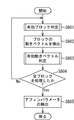
図3は、図2のステップS202における処理(適正領域を抽出する処理)の一例を説明するフローチャートである。この処理は、デジタル画像データ毎に行われる。
露出がアンダーな状態(露光量が少ない状態)で撮影された画像には、黒つぶれと呼ばれる階調が再現できない領域(暗い領域)が生じる場合がある。この領域では、画像の特徴が失われている。従って、複数のデジタル画像データにおける相対的な位置のずれを、この領域を含めて検出すると、誤判定を引き起こす可能性がある。そこで、この領域を除外するため、ステップS301において、領域抽出部106は、入力したデジタル画像データの画素の値が、予め定められた閾値Tl以上であるか否かを判定する。
Below, an example of the detailed process of each step shown in FIG. 2 is demonstrated.
FIG. 3 is a flowchart for explaining an example of the processing (processing for extracting an appropriate region) in step S202 of FIG. This process is performed for each digital image data.
In an image shot with underexposure (a state where the amount of exposure is small), there may be a region (dark region) in which a gradation called blackout cannot be reproduced. In this region, image features are lost. Therefore, if a relative positional shift in a plurality of digital image data is detected including this region, there is a possibility of causing an erroneous determination. Therefore, in order to exclude this region, in step S301, the
この判定の結果、入力したデジタル画像データの画素の値が、予め定められた閾値Tlよりも小さければ、その画素を黒つぶれしている領域の画素と判断して、ステップS302に進む。そして、領域抽出部106は、その画素を、複数のデジタル画像データにおける相対的な位置のずれを検出する際に用いる画素から除外する。即ち、黒つぶれしている領域の画素は、位置ずれ検出部108での検出対象から除外する。
一方、入力したデジタル画像データの画素の値が、予め定められた閾値Tl以上であれば、ステップS303に進む。
If the value of the pixel of the input digital image data is smaller than the predetermined threshold value Tl as a result of this determination, the pixel is determined to be a pixel in a blackened area, and the process proceeds to step S302. Then, the
On the other hand, if the pixel value of the input digital image data is greater than or equal to a predetermined threshold value Tl, the process proceeds to step S303.
露出がオーバーな状態(露光量が多い状態)で撮影された画像には、白とびと呼ばれる階調が再現できない領域(明るい領域)が生じる場合がある。この領域では、画像の特徴が失われている。従って、複数のデジタル画像データにおける相対的な位置のずれを、この領域を含めて検出すると、誤判定を引き起こす可能性がある。そこで、この領域を除外するため、ステップS303において、領域抽出部106は、入力したデジタル画像データの画素の値が、予め定められた閾値Th以下であるか否かを判定する。この判定の結果、入力したデジタル画像データの画素の値が、予め定められた閾値Thよりも大きければ、その画素を白とびしている領域の画素と判断して、前述したステップS302に進む。そして、ステップS302において、領域抽出部106は、白とびしている領域の画素を、位置ずれ検出部108での検出対象から除外する。
In an image captured in an overexposed state (a state where the amount of exposure is large), there may be a region (bright region) in which gradation cannot be reproduced, which is called overexposure. In this region, image features are lost. Therefore, if a relative positional shift in a plurality of digital image data is detected including this region, there is a possibility of causing an erroneous determination. Therefore, in order to exclude this region, in step S303, the
一方、入力したデジタル画像データの画素の値が、予め定められた閾値Th以上であれば、ステップS304に進む。そして、領域抽出部106は、ステップS303において値が閾値Th以上であると判定した画素を、複数のデジタル画像データにおける相対的な位置のずれを検出する際に用いる画素の候補とする。即ち、領域抽出部106は、入力したデジタル画像データの画素のうち、値が閾値Tl以上閾値Th以下の範囲内にある画素のみを、階調性を保持している適正領域の画素とし、その画素を位置ずれ検出部108での検出対象の候補とする。
On the other hand, if the pixel value of the input digital image data is greater than or equal to a predetermined threshold Th, the process proceeds to step S304. Then, the
次に、ステップS305において、領域抽出部106は、入力したデジタル画像データの全ての画素に対する処理を終えたか否かを判定する。この判定の結果、入力したデジタル画像データの全ての画素に対する処理を終えていない場合には、入力したデジタル画像データの全ての画素についての処理が終了するまで、ステップS301〜S305の処理を繰り返し行う。そして、入力したデジタル画像データの全ての画素について処理が終わると、一画面分の適正領域が抽出される。そして、図2のフローチャートに戻る。
Next, in step S305, the
図4は、図2のステップS203における処理(画素単位の共通領域の抽出処理)の一例を説明するフローチャートである。この処理は、適正領域を求めた画像間で行われる。尚、ここでは、説明を簡単にするために、2つのデジタル画像データ間での処理を行う場合を例に挙げて説明する。そして、以下の説明では、これら2つのデジタル画像データを、それぞれ第1の入力画像及び第2の入力画像と称する。 FIG. 4 is a flowchart for explaining an example of the processing in step S203 in FIG. This process is performed between images for which an appropriate area has been obtained. Here, in order to simplify the description, a case where processing between two digital image data is performed will be described as an example. In the following description, these two digital image data are referred to as a first input image and a second input image, respectively.
まず、ステップS401において、領域抽出部106は、第1の入力画像の画素が適正領域内の画素であるか否かを判定する。この判定の結果、第1の入力画像の画素が適正領域内の画素でなければ、ステップS402に進む。そして、領域抽出部106は、その画素を、位置ずれ検出部108での検出対象から除外する。尚、以下の説明において、位置ずれ検出部108での検出対象から除外した画素を、必要に応じて除外画素と称する。
First, in step S401, the
一方、第1の入力画像の画素が適正領域内の画素であれば、ステップS403に進む。そして、領域抽出部106は、第2の入力画像の画素が適正領域内の画素であるか否かを判定する。ここで、領域抽出部106は、ステップS401で判定した第1の入力画像の画素と同一位置の画素を第2の入力画像から抽出し、抽出した画素が適正領域内の画素であるか否かを判定する。この判定の結果、第2の入力画像の画素が適正領域内の画素でなければ、ステップS402に進み、領域抽出部106は、その画素を、位置ずれ検出部108での検出対象から除外する。
On the other hand, if the pixel of the first input image is a pixel in the appropriate region, the process proceeds to step S403. Then, the
一方、第2の入力画像の画素が適正領域内の画素であれば、ステップS404に進む。そして、領域抽出部106は、ステップS401、S403で適正領域内にあると判定した2つの画素を共通領域の画素とし、それら2つの画素を、位置ずれ検出部108で検出対象とする。即ち、領域抽出部106は、第1の入力画像の画素と、第2の入力画像の画素との両方が、適正範囲の中にある画素である場合に限り、それらの画素を共通領域の画素とし、それら2つの画素を、位置ずれ検出部108での検出対象とする。尚、以下の説明において、位置ずれ検出部108での検出対象となる画素を、必要に応じて共通画素と称する。
On the other hand, if the pixel of the second input image is a pixel in the appropriate region, the process proceeds to step S404. Then, the
次に、ステップS405において、領域抽出部106は、第1の入力画像と第2の入力画像との全ての画素について処理を終えたか否かを判定する。この判定の結果、第1の入力画像と第2の入力画像との全ての画素について処理を終えていない場合には、第1の入力画像と第2の入力画像との全ての画素についての処理が終了するまで、ステップS401〜S405の処理を繰り返し行う。そして、第1の入力画像と第2の入力画像との全ての画素について処理が終わると、一組分の共通領域が抽出される。
Next, in step S405, the
尚、例えば、3枚の画像を用いてダイナミックレンジの拡大を図る場合には、以下のようにすればよい。まず、1枚目の画像と2枚目の画像との間で図4の処理を行った後、2枚目の画像と3枚目の画像との間で図4の処理を行う。そして、3枚の画像の画素の全てが適正領域である場合に、それらの画素を共通領域の画素とする。 For example, when the dynamic range is expanded using three images, the following may be performed. First, the processing of FIG. 4 is performed between the first image and the second image, and then the processing of FIG. 4 is performed between the second image and the third image. If all the pixels of the three images are in the appropriate area, those pixels are set as the pixels in the common area.
図5は、図4に続く処理(ブロック単位の共通領域の抽出方法)の一例を説明するフローチャートである。図5に示す処理は、後述するようにして複数のデジタル画像データの位置のずれをブロック単位で検出する際に、その位置のずれの検出精度を向上させるための処理であり、図4で求めた共通領域よりも更に検出領域を狭める処理となる。 FIG. 5 is a flowchart for explaining an example of the process (extraction method of a common area in units of blocks) following FIG. The process shown in FIG. 5 is a process for improving the detection accuracy of the position shift when detecting the position shift of a plurality of digital image data in units of blocks as will be described later. This is a process of narrowing the detection area further than the common area.
まず、ステップS501において、領域抽出部106は、画面全体を一定の画素サイズのブロック(縦横1画素以上で構成されるブロック)に分割する。以下の処理は、このブロック単位での処理となる。
次に、ステップS502において、領域抽出部106は、ステップS501で分割したブロック内に、ステップS402で決定された除外画素があるか否かを判定する。この判定の結果、ステップS501で分割したブロック内に、ステップS402で決定された除外画素がある場合には、ステップS503に進む。そして、領域抽出部106は、そのブロックを、位置ずれ検出部108での検出対象から除外する。尚、以下の説明において、位置ずれ検出部108での検出対象から除外した画素を、必要に応じて除外ブロックと称する。
First, in step S501, the
Next, in step S502, the
一方、ステップS501で分割したブロック内に、ステップS402で決定された除外画素がない場合には、ステップS504に進む。そして、領域抽出部106は、ステップS502で除外画素がないと判定されたブロックに対して検出される動きベクトルのサーチ範囲内のブロック(後述する参照画像のブロック)に、除外画素があるか否かを判定する。この判定の結果、サーチ範囲内に除外画素がある場合には、ステップS503に進み、領域抽出部106は、それら複数のブロックを、位置ずれ検出部108での検出対象から除外する。
On the other hand, if there is no excluded pixel determined in step S402 in the block divided in step S501, the process proceeds to step S504. Then, the
一方、ステップS502で除外画素がないと判定されたブロックと、そのブロックに対して検出される動きベクトルのサーチ範囲内のブロックとに除外画素が無い場合には(ステップS504のNo)、ステップS505に進む。そして、領域抽出部106は、それら複数のブロックを、位置ずれ検出部108での検出対象とする。尚、以下の説明において、位置ずれ検出部108での検出に用いるブロックを、必要に応じて共通ブロックと称する。
On the other hand, when there is no excluded pixel in the block determined to have no excluded pixel in step S502 and the block within the motion vector search range detected for the block (No in step S504), step S505 is performed. Proceed to Then, the
次に、ステップS506において、領域抽出部106は、ステップS501で分割した全てのブロックに対して処理を終えたか否かを判定する。この判定の結果、ステップS501で分割した全てのブロックに対して処理を終えていない場合には、処理を終えるまでステップS502〜506を繰り返し行う。そして、ステップS501で分割した全てのブロックに対してステップS502〜S506の処理が終わったところで、図2のフローチャートに戻る。
Next, in step S506, the
図6は、図2のステップS204における処理(共通領域のレベル補正処理)の一例を説明するフローチャートである。尚、ここでも、説明を簡単にするために、2つのデジタル画像データ(第1及び第2の入力画像)間での処理を行う場合を例に挙げて説明する。 FIG. 6 is a flowchart illustrating an example of the process (common area level correction process) in step S204 of FIG. In addition, here, in order to simplify the description, a case where processing between two digital image data (first and second input images) is performed will be described as an example.
複数のデジタル画像データの位置のずれの検出は、一般的に、位置のずれの検出対象である複数のデジタル画像データ間の相関値に基づいて行われる。しかしながら、位置のずれの検出対象である複数のデジタル画像データ間で輝度レベルが合致していないと、それら複数のデジタル画像データ間の相関値の算出精度を下げることになる。画像データのダイナミックレンジを拡大する場合には、互いに異なる露出で撮影された複数のデジタル画像データ間で位置ずれを検出するので、対応する画像間の輝度レベルは大きく異なっている。従って、輝度レベルの補正は、位置のずれの検出精度を高めるための重要な処理となる。本実施形態の特徴の1つは、共通ブロック間で輝度レベルを合わせた後に、それら共通ブロックに生じている位置のずれを検出することにある。 In general, the detection of the position shift of a plurality of digital image data is performed based on the correlation value between the plurality of digital image data that is the detection target of the position shift. However, if the luminance levels do not match between the plurality of digital image data that are the position shift detection targets, the accuracy of calculating the correlation value between the plurality of digital image data is lowered. When the dynamic range of the image data is expanded, a positional shift is detected between a plurality of digital image data photographed at different exposures, so that the luminance levels between corresponding images are greatly different. Therefore, the correction of the luminance level is an important process for improving the detection accuracy of the position shift. One of the features of this embodiment is that, after matching the luminance levels between the common blocks, a positional shift occurring in the common blocks is detected.
まず、ステップS601において、レベル補正部107は、共通ブロック内における第1の入力画像の画素の平均値a1を算出する。
同様に、ステップS602において、レベル補正部107は、共通ブロック内における第2の入力画像の画素の平均値a2を算出する。
First, in step S601, the
Similarly, in step S602, the
次に、ステップS603において、レベル補正部107は、第1の入力画像のゲインr1を算出する。第1の入力画像のゲインr1と、平均値a1、a2との関係は、式(1)で表すことができる。
r1=(a1+a2)/(2×a1) ・・・ (1)
Next, in step S603, the
r1 = (a1 + a2) / (2 × a1) (1)
同様に、ステップS604において、レベル補正部107は、第2の入力画像のゲインr2を算出する。第2の入力画像のゲインr2と、平均値a1、a2との関係は、式(2)で表すことができる。
r2=(a1+a2)/(2×a2) ・・・ (2)
Similarly, in step S604, the
r2 = (a1 + a2) / (2 × a2) (2)
次に、ステップS605において、レベル補正部107は、第1の入力画像の各画素の画素値に、ゲインr1を乗じて輝度レベルの補正値を算出する。即ち、第1の入力画像の各画素の画素値に、ゲインr1を乗じた値が輝度レベルの補正値となる。
同様に、ステップS606において、レベル補正部107は、第2の入力画像の各画素の画素値に、ゲインr2を乗じて輝度レベルの補正値を算出する。即ち、第2の入力画像の各画素の画素値に、ゲインr2を乗じた値が輝度レベルの補正値となる。こうして、一連のレベル補正処理を終えると、図2のフローチャートに戻る。
Next, in step S605, the
Similarly, in step S606, the
図7は、図2のステップS205における処理(位置ずれを検出処理)の一例を説明するフローチャートである。ここでは、ブロック毎に動きベクトルを求め、求めた動きベクトルを用いて、画面全体の動き量をアフィンパラメータとして求める方法を一例として説明する。 FIG. 7 is a flowchart for explaining an example of processing (position shift detection processing) in step S205 of FIG. Here, a method of obtaining a motion vector for each block and obtaining the motion amount of the entire screen as an affine parameter using the obtained motion vector will be described as an example.
ステップS801において、位置ずれ検出部108は、ブロック毎に動きベクトルを求めるための前処理として、有効ブロックの判定を行う。これは、正しい動きベクトルが求まらない可能性のあるブロックを除外する処理である。詳細は後述する。
次に、ステップS802において、位置ずれ検出部108は、ブロックの動きベクトルを算出する。ここでは、一般的なブロックマッチング法を用いてブロックの動きベクトルを算出する場合を例に挙げて説明する。
In step S <b> 801, the positional
Next, in step S802, the
ブロックマッチング法では、マッチングの評価値としてブロック内の画素間の差分二乗和又は差分絶対値和を用いる。動きベクトルを求める対象ブロックにおける参照画像内のブロックを参照画像のサーチ範囲内で順次動かしなら評価値を求めていく。サーチ範囲内で求めた全ての評価値の中から最小の評価値を持つ位置(参照画像のブロック)が、対象ブロックと最も相関の高い位置(ブロック)となる。そして、対象ブロックと、その対象ブロックと最も相関の高いブロックとの移動量が動きベクトルとなる。ここで、サーチ範囲内で1画素ずつ評価値を求めていく方法をフルサーチと呼ぶ。これに対し、サーチ範囲内の間引かれた画素の中から最小の評価値を求め、求めた最小の評価値を有する画素の近傍の画素に対して細かくサーチする方法を、ステップサーチと呼ぶ。ステップサーチは高速に動きベクトルを求める方法としてよく知られている。 In the block matching method, a sum of squared differences or a sum of absolute differences between pixels in a block is used as a matching evaluation value. If the blocks in the reference image in the target block for which the motion vector is to be calculated are sequentially moved within the search range of the reference image, the evaluation value is obtained. The position (block of reference image) having the smallest evaluation value among all the evaluation values obtained within the search range is the position (block) having the highest correlation with the target block. The amount of movement between the target block and the block having the highest correlation with the target block is the motion vector. Here, the method of obtaining the evaluation value for each pixel within the search range is called full search. On the other hand, a method of obtaining a minimum evaluation value from pixels thinned out in the search range and performing a fine search for pixels near the pixel having the obtained minimum evaluation value is called a step search. Step search is well known as a method for obtaining a motion vector at high speed.
次に、ステップS803において、位置ずれ検出部108は、有効動きベクトルの判定を行う。これは、求めた動きベクトルのうち、算出結果が正しくないと判断されるものを除外する処理である。詳細は後述する。
次に、ステップS804において、位置ずれ検出部108は、全てのブロックに対して処理を終えたか否かを判定する。この判定の結果、全てのブロックに対して処理を終えていない場合には、処理を終えるまでステップS801〜S804の処理を繰り返し行う。そして、全てのブロックに対して処理を終えると、ステップS805に進む。そして、位置ずれ検出部108は、ステップS803で得られた有効な動きベクトルを用いて、アフィンパラメータを検出する。
Next, in step S <b> 803, the positional
Next, in step S804, the
図8は、アフィンパラメータの検出を説明するための図である。
図8に示すように、対象ブロックの中心座標が、(x,y)であるとする。そして、有効な動きベクトルの算出結果から、対象ブロックの中心座標(x,y)が、参照画像におけるブロックの中心座標(x',y')に移動したとすると、これらの関係は,式(3)のように表すことができる。
FIG. 8 is a diagram for explaining the detection of affine parameters.
As shown in FIG. 8, it is assumed that the center coordinates of the target block are (x, y). If the center coordinate (x, y) of the target block is moved to the center coordinate (x ′, y ′) of the block in the reference image from the calculation result of the effective motion vector, these relationships are expressed by the formula ( It can be expressed as 3).

ここで、式(3)の右辺における3×3の行列がアフィン変換行列である。このアフィン変換行列の各要素がアフィンパラメータである。アフィンパラメータa、b、d、eがそれぞれ1、0、0、1(a=1,b=0,d=0,e=1)のとき、この変換は平行移動となる。このとき、アフィンパラメータcが水平方向の移動量となり、アフィンパラメータfが垂直方向の移動量となる。また、回転角をθとすると、回転移動は、式(4)〜(7)のように表すことができる。 Here, the 3 × 3 matrix on the right side of Equation (3) is the affine transformation matrix. Each element of this affine transformation matrix is an affine parameter. When the affine parameters a, b, d, and e are 1, 0, 0, 1 (a = 1, b = 0, d = 0, e = 1), this conversion is a parallel movement. At this time, the affine parameter c is the amount of movement in the horizontal direction, and the affine parameter f is the amount of movement in the vertical direction. Further, when the rotation angle is θ, the rotational movement can be expressed as in equations (4) to (7).
a=cosθ ・・・(4)
b=−sinθ ・・・(5)
d=sinθ ・・・(6)
e=cosθ ・・・(7)
a = cos θ (4)
b = −sin θ (5)
d = sin θ (6)
e = cos θ (7)
また、式(3)は、一般化した行列の形式で、式(8)のように表現することができる。
x'=A・x ・・・(8)
ここで、xとx'は1×3の行列、Aは3×3の行列である。有効な動きベクトルがn個であった場合、対象画像の座標値は、式(9)のようにn×3の行列で表現できる。
X=(x1x2・・・xn) ・・・(9)
Moreover, Formula (3) can be expressed as Formula (8) in the form of a generalized matrix.
x ′ = A · x (8)
Here, x and x ′ are 1 × 3 matrices, and A is a 3 × 3 matrix. When there are n effective motion vectors, the coordinate value of the target image can be expressed by an n × 3 matrix as shown in Equation (9).
X = (x 1 x 2 ... X n ) (9)
同様に、移動後の座標値も式(10)のようにn×3の行列で表現できる。
X'=(x1'x2'・・・xn') ・・・(10)
よって、n個の動きベクトルに対しては、式(11)のような表現となる。
X'=A・X ・・・(11)
Similarly, the coordinate values after movement can be expressed by an n × 3 matrix as shown in Equation (10).
X '= (x 1' x 2 '··· x n') ··· (10)
Therefore, for n motion vectors, the expression is as shown in Expression (11).
X ′ = A · X (11)
即ち、式(11)におけるアフィン変換行列Aを求めれば、それが画面全体の位置ずれ量になる。式(11)を変形すると、アフィン変換行列Aは式(12)のようにして求まる。
A=X'・XT・(X・XT)-1 ・・・(12)
That is, if the affine transformation matrix A in Equation (11) is obtained, it becomes the amount of displacement of the entire screen. By transforming equation (11), the affine transformation matrix A is obtained as in equation (12).
A = X ′ · X T · (X · X T ) −1 (12)
以上のように、複数のデジタル画像データの位置のずれを求める場合には、アフィンパラメータを用いて、複数のデジタル画像データの動き量を表現できる。このため、デジタルカメラを保持しているときに起こるシフトぶれによる動き量以外にも、面内方向で生じるロールぶれや前後方向で生じるズームぶれ等による動き量を求めることが可能である。 As described above, when the positional deviation of a plurality of digital image data is obtained, the amount of motion of the plurality of digital image data can be expressed using the affine parameters. For this reason, in addition to the amount of movement due to shift blur that occurs when holding the digital camera, it is possible to determine the amount of movement due to roll blur that occurs in the in-plane direction, zoom blur that occurs in the front-rear direction, and the like.
ここで、図9のフローチャートを参照しながら、図7のステップS801における処理(有効ブロックの判定処理)の一例を説明する。
ブロックマッチング法によりブロック間の相関を求めようとする場合、ブロック内の画像が何らかの特徴量を持っている必要がある。平坦で殆ど直流成分しか含んでいないブロックでは正しい動きベクトルを求めることはできない。逆に水平方向や垂直方向にエッジを含んでいると、マッチングがとり易くなると考えられる。図9に示す処理は、このような平坦部のブロックを除外するための処理の一例である。尚、ここでは、説明を簡単にするために、1つのブロックに対して処理を行う場合を例に挙げて説明する。
Here, an example of processing (valid block determination processing) in step S801 in FIG. 7 will be described with reference to the flowchart in FIG.
When trying to obtain the correlation between blocks by the block matching method, the image in the block needs to have some feature amount. A correct motion vector cannot be obtained for a flat block containing almost only a DC component. On the other hand, if the edge is included in the horizontal direction or the vertical direction, it is considered that matching can be easily performed. The process shown in FIG. 9 is an example of a process for excluding such a flat portion block. Here, in order to simplify the description, a case where processing is performed on one block will be described as an example.
まず、ステップS901において、位置ずれ検出部108は、ブロック内の水平方向の1つのラインにおける画素値の最大値と最小値との差分値を算出する。例えば、ブロックのサイズが50×50の画素で構成されているとすると、ブロック内の水平方向の50個の画素から最大値と最小値とを求め、その最大値と最小値との差分値を算出する。
First, in step S901, the
次に、ステップS902において、位置ずれ検出部108は、ブロックの全ての水平ラインに対して、ステップS901の算出を行ったか否かを判定する。前述した例では、ステップS901の算出を、水平ライン数分、即ち50回繰り返し行ったか否かを判定する。この判定の結果、ブロックの全ての水平ラインに対して、ステップS901の算出を行っていない場合には、ブロックの全ての水平ラインに対して、ステップS901の算出を行うまでステップS901、S902を繰り返し行う。
Next, in step S902, the positional
そして、ブロックの全ての水平ラインに対して、ステップS901の算出を行うと、ステップS903に進む。そして、位置ずれ検出部108は、ステップS901で算出した差分値の中から最大の差分値を求める。前述した例では、50個の差分値の中から最大の差分値を求める。
When the calculation in step S901 is performed for all horizontal lines of the block, the process proceeds to step S903. Then, the
次に、ステップS904において、位置ずれ検出部108は、予め設定された閾値Txよりも、ステップS903で求めた最大の差分値が大きいか否かを判定する。この判定の結果、予め設定された閾値Txよりも、ステップS903で求めた最大の差分値が大きくなければ、位置ずれ検出部108は、処理対象のブロックが、水平方向には特徴量を持たないブロックであるとみなしてステップS905に進む。そして、位置ずれ検出部108は、処理対象のブロックを無効ブロックと判定する。
Next, in step S904, the
一方、予め設定された閾値Txよりも、ステップS903で求めた最大の差分値が大きければ、位置ずれ検出部108は、処理対象のブロックが、水平方向に特徴量を持つブロックであるとみなして、垂直方向で水平方向と同様の検証を行う。
まず、ステップS906において、位置ずれ検出部108は、ブロック内の垂直方向の1つのラインにおける画素値の最大値と最小値との差分値を算出する。前述した例では、ブロック内の垂直方向の50個の画素から最大値と最小値とを求め、その最大値と最小値との差分値を算出する。
On the other hand, if the maximum difference value obtained in step S903 is larger than the preset threshold value Tx, the
First, in step S906, the
次に、ステップS907において、位置ずれ検出部108は、ブロックの全ての垂直ラインに対して、ステップS906の算出を行ったか否かを判定する。前述した例では、ステップS906の算出を、垂直ライン数分、即ち50回繰り返し行ったか否かを判定する。この判定の結果、ブロックの全ての垂直ラインに対して、ステップS906の算出を行っていない場合には、ブロックの全ての垂直ラインに対して、ステップS906の算出を行うまでステップS906、S907を繰り返し行う。
Next, in step S907, the positional
そして、ブロックの全ての垂直ラインに対して、ステップS906の算出を行うと、ステップS908に進む。そして、位置ずれ検出部108は、ステップS906で算出した差分値の中から最大の差分値を求める。前述した例では、50個の差分値の中から最大の差分値を求める。
When the calculation in step S906 is performed for all the vertical lines of the block, the process proceeds to step S908. Then, the
次に、ステップS909において、位置ずれ検出部108は、予め設定された閾値Tyよりも、ステップS908で求めた最大の差分値が大きいか否かを判定する。この判定の結果、予め設定された閾値Tyよりも、ステップS908で求めた最大の差分値が大きくなければ、位置ずれ検出部108は、処理対象のブロックが、垂直方向には特徴量を持たないブロックであるとみなしてステップS905に進む。そして、前述したように、位置ずれ検出部108は、処理対象のブロックを無効ブロックと判定する。
Next, in step S909, the positional
一方、予め設定された閾値Tyよりも、ステップS908で求めた最大の差分値が大きければ、位置ずれ検出部108は、処理対象のブロックが、垂直方向及び水平方向の両方向に特徴量を持つブロックであるとみなす。この場合、正確なブロックマッチングを行えることが期待できる。そこで、ステップS910に進み、位置ずれ検出部108は、処理対象のブロックを有効ブロックと判定する。
On the other hand, if the maximum difference value obtained in step S908 is larger than the preset threshold value Ty, the
次に、図10のフローチャートを参照しながら、図7のステップS803における処理(有効動きベクトルの判定処理)の一例を説明する。
まず、ステップS1001において、位置ずれ検出部108は、図7のステップS802で検出した動きベクトルを入力する。そうすると、ステップS1002において、位置ずれ検出部108は、その動きベクトルの発生頻度を算出する。
Next, an example of the process (valid motion vector determination process) in step S803 in FIG. 7 will be described with reference to the flowchart in FIG.
First, in step S1001, the positional
次に、ステップS1003において、位置ずれ検出部108は、図7のステップS802で検出した全ての動きベクトルの発生頻度を求め終えたか否かを判定する。この判定の結果、図7のステップS802で検出した全ての動きベクトルの発生頻度を求め終えていない場合には、求め終えるまでステップS1001〜S1003を繰り返し行う。そして、図7のステップS802で検出した全ての動きベクトルの発生頻度を求め終えると、ステップS1004に進む。そして、位置ずれ検出部108は、ステップS1002で求めた動きベクトルの発生頻度に基づいて、最大発生頻度の動きベクトルを求める。
Next, in step S1003, the
次に、ステップS1005において、位置ずれ検出部108は、図7のステップS802で検出した動きベクトルを再度入力する。そして、ステップS1006において、位置ずれ検出部108は、再度入力した動きベクトルが最大発生頻度の動きベクトル、又はその動きベクトルの近傍の動きベクトルであるか否かを判定する。画面全体のぶれが、前述したシフトぶれのみである場合、各ブロックの動きベクトルは、最大発生頻度の動きベクトルに略一致すると考えられる。また、前述したロールぶれを伴う場合には、最大発生頻度の動きベクトルの近傍に多くの動きベクトルが発生すると考えられる。
Next, in step S1005, the positional
従って、ステップS1006の判定の結果、再度入力した動きベクトルが、最大発生頻度の動きベクトル、又はその動きベクトルの近傍の動きベクトルである場合には、ステップS1007に進む。そして、位置ずれ検出部108は、その動きベクトルを有効動きベクトルと判定する。
一方、再度入力した動きベクトルが、最大発生頻度の動きベクトル、又はその動きベクトルの近傍の動きベクトルでない場合には、ステップS1008に進む。そして、位置ずれ検出部108は、その動きベクトルを無効動きベクトルと判定する。
Therefore, if the result of determination in step S1006 is that the input motion vector is a motion vector with the maximum occurrence frequency or a motion vector in the vicinity of the motion vector, the process proceeds to step S1007. Then, the positional
On the other hand, if the input motion vector is not the motion vector having the maximum occurrence frequency or a motion vector in the vicinity of the motion vector, the process proceeds to step S1008. Then, the
次に、ステップS1009において、位置ずれ検出部108は、図7のステップS802で検出した全ての動きベクトルに対して処理が終わったか否かを判定する。この判定の結果、図7のステップS802で検出した全ての動きベクトルに対して処理が終わっていなければ、終わるまでステップS1005〜S1009を繰り返し行う。
Next, in step S1009, the positional
図11は、図2のステップS207で行われる画像データの合成処理の一例を説明する図である。画像データの合成は、画素値(画素レベル)がある閾値以下の場合には、低輝度側のデジタル画像データを用い、閾値より大きい場合には、高輝度側のデジタル画像データを用いるというのが基本である。しかしながら実際には、設定された閾値が低輝度側と高輝度側との間の不連続点となってしまうのを避けるための処理を行う。ここでは、低輝度側と高輝度側とが共通に持つ値の範囲内で、2つの閾値Ta、Tbを設定している。本実施形態の画像合成部110は、これら2つの閾値Ta、Tbを用いて画素値(画素レベル)を判定することにより、低輝度側から高輝度側へのデジタル画像データの混合比が1から0へ順次(徐々に)変化するように画像データの合成処理を行う。
FIG. 11 is a diagram illustrating an example of the image data synthesis process performed in step S207 of FIG. When synthesizing image data, the digital image data on the low luminance side is used when the pixel value (pixel level) is below a certain threshold value, and the digital image data on the high luminance side is used when the pixel value is larger than the threshold value. Basic. However, in practice, a process for avoiding that the set threshold value becomes a discontinuous point between the low luminance side and the high luminance side is performed. Here, two threshold values Ta and Tb are set within a range of values that the low luminance side and the high luminance side have in common. The
以上のように本実施形態では、領域抽出部106は、複数のデジタル画像データの画素の中から、黒つぶれや白とび等によって階調性が失われた領域の画素を除いた画素を適正画素とする。そして、領域抽出部106は、複数のデジタル画像データの同一位置の画素であって、共に適正画素である画素を共通画素とし、そうでない画素を除外画素とする。更に領域抽出部106は、複数のデジタル画像データの画面全体をブロック化する。領域抽出部106は、動きベクトルの検出対象のブロックと、そのブロックに対する参照画像のブロックとの双方に除外画素が含まれていなければ、それらのブロックを共通ブロックとする。レベル補正部107は、共通ブロック内における画素値(輝度レベル)の平均値a1、a2を求め、求めた平均値a1、a2を用いて、共通ブロックの輝度レベルを合わせる。位置ずれ検出部108は、輝度レベルが合った共通ブロックを用いて位置のずれを検出し、位置補正部109は、その位置のずれ量に応じて、複数のデジタル画像データの位置を補正する。
As described above, in the present embodiment, the
以上のように、互いに輝度レベルを合わせた共通ブロックを用いて動きベクトルを検出することによって、複数のデジタル画像データの位置のずれを検出する。そして、検出したずれの量に応じて、複数のデジタル画像データの位置を合わせてから、複数のデジタル画像データを合成する。従って、ダイナミックレンジの大きな画像データを生成する際に行う複数のデジタル画像データの位置合わせを従来よりも精度よく行うことが可能となる。 As described above, by detecting a motion vector using a common block whose luminance levels are matched to each other, a position shift of a plurality of digital image data is detected. Then, after aligning the positions of the plurality of digital image data in accordance with the detected amount of deviation, the plurality of digital image data is synthesized. Therefore, it is possible to perform alignment of a plurality of digital image data performed when generating image data having a large dynamic range with higher accuracy than in the past.
また、本実施形態では、水平方向又は垂直方向に特徴量を持たないブロックを処理対象から除外するようにした。また、シフトぶれによる動き量、面内方向で生じるロールぶれ、又は前後方向で生じるズームぶれに起因すると推定される動きベクトルだけを用いて、複数のデジタル画像データの位置のずれを検出するようにした。従って、複数のデジタル画像データの位置合わせの精度をより向上させることが可能になる。 Further, in the present embodiment, blocks that do not have a feature amount in the horizontal direction or the vertical direction are excluded from processing targets. In addition, it is possible to detect a shift in the position of a plurality of digital image data using only a motion vector estimated to be caused by an amount of movement due to shift blur, roll blur occurring in the in-plane direction, or zoom blur occurring in the front-rear direction. did. Therefore, it is possible to further improve the accuracy of alignment of a plurality of digital image data.
(第2の実施形態)
次に、本発明の第2実施形態について説明する。前述した第1の実施形態では、共通ブロック内における画素値の平均値a1、a2を求め、求めた平均値a1、a2を用いて、共通ブロックの輝度レベルを合わせるようにした。これに対し、本実施形態では、撮像制御部102で得られた撮像情報を利用して、共通ブロックの輝度レベルを合わせるようにする。このように、本実施形態と前述した第1の実施形態とは、共通ブロックの輝度レベルを合わせるための処理の一部が主として異なる。従って、以下の説明において、前述した第1の実施形態と同一の部分については、図1〜図11に付した符号と同一の符号を付す等して詳細な説明を省略する。
(Second Embodiment)
Next, a second embodiment of the present invention will be described. In the first embodiment described above, the average values a1 and a2 of the pixel values in the common block are obtained, and the luminance levels of the common block are matched using the obtained average values a1 and a2. On the other hand, in the present embodiment, the luminance level of the common block is adjusted using the imaging information obtained by the
図12は、本実施形態における撮像装置の一例であるデジタルカメラの構成の一例を示したブロック図である。
図12に示すデジタルカメラと、図1に示した第1の実施形態のデジタルカメラとの違いは、画像処理部1201内のレベル補正部1202の処理において、撮影制御部102で得られる撮像情報を利用することにある。図13のフローチャートを参照しながら、本実施形態のレベル補正部1202の処理(図2のステップS204における処理(共通領域のレベル補正処理))の一例を説明する。尚、ここでは、説明を簡単にするために、2つのデジタル画像データ(第1及び第2の入力画像)間での処理を行う場合を例に挙げて説明する。
FIG. 12 is a block diagram illustrating an example of a configuration of a digital camera that is an example of an imaging apparatus according to the present embodiment.
The difference between the digital camera shown in FIG. 12 and the digital camera of the first embodiment shown in FIG. 1 is that the imaging information obtained by the
撮影制御部102で得られる撮影情報は、具体的には、適正露出からどれだけアンダー又はオーバーの露出で撮影したかという情報である。この情報を用いることで、第1の実施形態の図6で説明した平均値の演算を行うことなく、輝度レベルの補正が可能となる。
まず、ステップS701において、レベル補正部1202は、第1の入力画像の撮影情報を取得する。
同様に、ステップS702において、レベル補正部1202は、第2の入力画像の撮影情報を取得する。
Specifically, the shooting information obtained by the
First, in step S701, the
Similarly, in step S702, the
次に、ステップS703において、レベル補正部1202は、第1の入力画像の撮影情報を用いて、第1の入力画像のゲインr1を算出する。例えば、第1の入力画像が1段アンダーで撮影されたとすると、第1の入力画像を得た際の露出時間は本来の半分ということになる。従って、適正な明るさにするためのゲインr1は「2」となる。
同様に、ステップS704において、レベル補正部1202は、第2の入力画像の撮影情報を用いて、第2の入力画像のゲインr2を算出する。例えば、第2の入力画像が1段オーバーで撮影されたとすると、第2の入力画像を得た際の露出時間は本来の2倍ということになる。従って、適正な明るさにするためのゲインr2は「1/2」となる。
Next, in step S703, the
Similarly, in step S704, the
次に、ステップS705において、レベル補正部1202は、第1の入力画像の各画素の画素値に、ゲインr1を乗じて輝度レベルの補正値を算出する。即ち、第1の入力画像の各画素に、ゲインr1を乗じた値が輝度レベルの補正値となる。
同様に、ステップS706において、レベル補正部1202は、第2の入力画像の各画素の画素値に、ゲインr2を乗じて輝度レベルの補正値を算出する。即ち、第2の入力画像の各画素に、ゲインr2を乗じた値が輝度レベルの補正値となる。こうして、一連のレベル補正処理を終え、図2のフローチャートに戻る。
Next, in step S705, the
Similarly, in step S706, the
以上のように本実施形態では、適正露出からのずれに関する撮像情報を用いて、共通ブロックの輝度レベルを合わせるようにした。従って、第1の実施形態のように、平均値a1、a2の演算を行う処理を省略できる。よって、本実施形態では、前述した第1の実施形態で説明した効果に加えて、複数のデジタル画像データの位置合わせを容易に行うことができるという効果を有する。 As described above, in this embodiment, the luminance level of the common block is adjusted using the imaging information regarding the deviation from the appropriate exposure. Therefore, the process of calculating the average values a1 and a2 can be omitted as in the first embodiment. Therefore, in this embodiment, in addition to the effect described in the first embodiment, there is an effect that a plurality of digital image data can be easily aligned.
尚、撮像装置(デジタルカメラ)内で前述した処理を行う場合には、撮像制御部102から撮像情報を得ることになる。ただし、PCのアプリケーションソフトウェアで後から処理する場合には、画像ファイル内に記録されている付加情報の中から、撮像情報を得て前述した処理と同様の処理をPC等で行うことになる。
Note that when the above-described processing is performed in the imaging apparatus (digital camera), imaging information is obtained from the
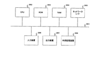
図14は、前述した第1及び第2の実施形態で説明した処理を実行可能なコンピュータのハードウェアの構成の一例を示す図である。尚、このコンピュータは、例えば、撮像装置とインタフェースを介して相互に接続可能であり、撮像装置で撮像された映像信号を入力して、前述した第1及び第2の実施形態で説明した処理を実行する。 FIG. 14 is a diagram illustrating an example of a hardware configuration of a computer capable of executing the processing described in the first and second embodiments. Note that this computer can be connected to the imaging apparatus via an interface, for example, and inputs the video signal captured by the imaging apparatus and performs the processing described in the first and second embodiments. Execute.
図14において、バス2001には、中央処理装置(CPU)2002、ROM2003、RAM2004、ネットワークインタフェース2005、入力装置2006、出力装置2007及び外部記憶装置2008が接続されている。CPU2002は、データの処理又は演算を行うと共に、バス2001を介して接続された各種構成要素を制御するものである。ROM2003には、予めCPU2002の制御手順(コンピュータプログラム)を記憶させておく。このコンピュータプログラムをCPU2002が実行することにより、コンピュータが起動する。
14, a central processing unit (CPU) 2002, a
外部記憶装置2008にコンピュータプログラムが記憶されており、そのコンピュータプログラムがRAM2004にコピーされて実行される。RAM2004は、データの入出力や送受信のためのワークメモリとして用いられたり、各構成要素の制御のための一時的な記憶領域として用いられたりする。
A computer program is stored in the
外部記憶装置2008は、例えばハードディスク記憶装置やCD−ROM等であり、画像データ等を記憶する。電源を切っても外部記憶装置2008の記憶内容は消えない。CPU2002は、RAM2004内のコンピュータプログラムを実行することにより、前述した実施形態の処理を行う。ネットワークインタフェース2005は、ネットワークに接続するためのインタフェースである。入力装置2006は、例えばキーボード及びマウス等であり、各種指定又は入力等を行うことができる。出力装置2007は、ディスプレイ及びプリンタ等である。
The
(本発明の他の実施形態)
前述した実施形態の機能を実現するべく各種のデバイスを動作させるように、該各種デバイスと接続された装置あるいはシステム内のコンピュータに対し、前記実施形態の機能を実現するためのソフトウェアのプログラムコードを供給してもよい。そのシステムあるいは装置のコンピュータ(CPUあるいはMPU)に格納されたプログラムに従って前記各種デバイスを動作させることによって実施したものも、本発明の範疇に含まれる。
(Other embodiments of the present invention)
In order to operate various devices to realize the functions of the above-described embodiments, program codes of software for realizing the functions of the above-described embodiments are provided to an apparatus or a computer in the system connected to the various devices. You may supply. What was implemented by operating said various devices according to the program stored in the computer (CPU or MPU) of the system or apparatus is also included in the category of the present invention.
また、この場合、前記ソフトウェアのプログラムコード自体が前述した実施形態の機能を実現することになる。また、そのプログラムコード自体、及びそのプログラムコードをコンピュータに供給するための手段、例えば、かかるプログラムコードを格納した記録媒体は本発明を構成する。かかるプログラムコードを記憶する記録媒体としては、例えばフレキシブルディスク、ハードディスク、光ディスク、光磁気ディスク、CD−ROM、磁気テープ、不揮発性のメモリカード、ROM等を用いることができる。 In this case, the program code of the software itself realizes the functions of the above-described embodiment. The program code itself and means for supplying the program code to a computer, for example, a recording medium storing the program code constitute the present invention. As a recording medium for storing the program code, for example, a flexible disk, a hard disk, an optical disk, a magneto-optical disk, a CD-ROM, a magnetic tape, a nonvolatile memory card, a ROM, or the like can be used.
また、コンピュータが供給されたプログラムコードを実行することにより、前述の実施形態の機能が実現されるだけでない。そのプログラムコードがコンピュータにおいて稼働しているオペレーティングシステムあるいは他のアプリケーションソフト等と共同して前述の実施形態の機能が実現される場合にもかかるプログラムコードは本発明の実施形態に含まれることは言うまでもない。 Further, the functions of the above-described embodiments are not only realized by executing the program code supplied by the computer. It goes without saying that the program code is also included in the embodiment of the present invention even when the function of the above-described embodiment is realized in cooperation with an operating system or other application software running on the computer. Yes.
さらに、供給されたプログラムコードがコンピュータの機能拡張ボードに備わるメモリに格納された後、そのプログラムコードの指示に基づいてその機能拡張ボードに備わるCPUが実際の処理の一部または全部を行う。その処理によって前述した実施形態の機能が実現される場合にも本発明に含まれることは言うまでもない。
また、供給されたプログラムコードがコンピュータに接続された機能拡張ユニットに備わるメモリに格納された後、そのプログラムコードの指示に基づいて機能拡張ユニットに備わるCPU等が実際の処理の一部または全部を行う。その処理によって前述した実施形態の機能が実現される場合にも本発明に含まれることは言うまでもない。
Further, after the supplied program code is stored in the memory provided in the function expansion board of the computer, the CPU provided in the function expansion board performs part or all of the actual processing based on the instruction of the program code. Needless to say, the present invention includes the case where the functions of the above-described embodiments are realized by the processing.
Further, after the supplied program code is stored in the memory provided in the function expansion unit connected to the computer, the CPU or the like provided in the function expansion unit performs part or all of the actual processing based on the instruction of the program code. Do. Needless to say, the present invention includes the case where the functions of the above-described embodiments are realized by the processing.
前述した各実施形態における処理の内容を前記記録媒体に適用する場合、その記録媒体には、先に説明したフローチャートに対応するプログラムコードが格納されることになる。 When the contents of the processing in each of the embodiments described above are applied to the recording medium, the program code corresponding to the flowchart described above is stored in the recording medium.
尚、前述した各実施形態は、複数の機器(例えば、ホストコンピュータ、インタフェース機器、リーダ、プリンタ等)から構成されるシステムに適用しても、一つの機器からなる装置(例えば、複写機、ファクシミリ装置等)に適用してもよい。 Note that each of the above-described embodiments can be applied to a system including a plurality of devices (for example, a host computer, an interface device, a reader, and a printer). For example, an apparatus).
また、前述した各実施形態は、何れも本発明を実施するにあたっての具体化の例を示したものに過ぎず、これらによって本発明の技術的範囲が限定的に解釈されてはならないものである。すなわち、本発明はその技術思想、またはその主要な特徴から逸脱することなく、様々な形で実施することができる。 In addition, each of the above-described embodiments is merely a specific example for carrying out the present invention, and the technical scope of the present invention should not be construed as being limited thereto. . That is, the present invention can be implemented in various forms without departing from the technical idea or the main features thereof.
101 撮像部
102 撮像制御部
103 A/D変換部
104、1201 画像処理部
105 メモリ部
106 領域抽出部
107、1202 レベル補正部
108 位置ずれ検出部
109 位置補正部
110 画像合成部
111 画像表示部
112 画像記録部
DESCRIPTION OF
Claims (12)
前記共通領域の画素値の平均値に基づいて、前記抽出手段により抽出された前記共通領域の輝度を前記複数の画像ごとに補正する輝度補正手段と、
前記輝度補正手段により輝度が補正された前記共通領域における前記複数の画像間の位置のずれに基づいて、前記複数の画像の位置を補正する位置補正手段と、
前記位置補正手段により位置が補正された複数の画像に基づいて、合成画像を生成する生成手段とを備え、
前記抽出手段は、前記複数の画像の同一位置における画素が共に階調性を保持しているときに、前記階調性を保持している画素を共通画素として抽出し、前記共通画素に基づいて前記共通領域を抽出することを特徴とする画像処理装置。 Extracting means for extracting, from among a plurality of images picked up under different exposure conditions, a common region that is a region having the gradation property common to the plurality of images from a region having the gradation property; ,
Luminance correction means for correcting the luminance of the common area extracted by the extraction means for each of the plurality of images based on an average value of pixel values of the common area;
Position correcting means for correcting the positions of the plurality of images based on positional deviations between the plurality of images in the common area whose luminance is corrected by the luminance correcting means;
Generating means for generating a composite image based on a plurality of images whose positions have been corrected by the position correcting means ;
The extraction means extracts pixels having the gradation property as common pixels when pixels at the same position of the plurality of images have gradation properties, and based on the common pixels An image processing apparatus that extracts the common area .
前記抽出手段は、前記動きベクトルの検出対象となるブロックの画素と前記動きベクトルの検出対象となるブロックに対する動きベクトルの検索範囲内にあるブロックの画素との全てが前記共通画素であるときに、前記ブロック内の画素が全て前記共通画素であるブロックを前記共通領域として抽出することを特徴とする請求項1ないし3の何れか1項に記載の画像処理装置。 Motion vector detection means for detecting a motion vector using a block composed of one or more vertical and horizontal pixels in the entire screen of the plurality of images,
The extraction means, when all the previous SL detecting subject to detection subject to be within the search range of the motion vector for the block block of pixels and the motion vector of the block pixel motion vector is the common pixel the image processing apparatus according to any one of claims 1 to 3, characterized in that pixels in the block to extract a block are all the common pixels as the common region.
前記位置補正手段は、前記アフィンパラメータを用いた変換により、前記複数の画像に生じた相対的なずれ量を補正することを特徴とする請求項6に記載の画像処理装置。 The detection means calculates an affine parameter indicating a motion amount of the plurality of images,
The image processing apparatus according to claim 6 , wherein the position correction unit corrects a relative shift amount generated in the plurality of images by conversion using the affine parameter.
前記撮像素子によって異なる露光条件で撮像された同一被写体の複数の画像を一時的に記憶する記憶手段と、
前記記憶手段に記憶された前記複数の画像の階調性を保持している領域から、前記複数の画像に共通の前記階調性を保持している領域である共通領域を抽出する抽出手段と、
前記共通領域の画素値の平均値に基づいて、前記抽出手段により抽出された前記共通領域の輝度を、前記複数の画像ごとに補正する輝度補正手段と、
前記輝度補正手段により輝度が補正された前記共通領域における前記複数の画像間の位置のずれに基づいて、前記複数の画像の位置を補正する位置補正手段と、
前記位置補正手段により位置が補正された複数の画像に基づいて、合成画像を生成する生成手段とを備え、
前記抽出手段は、前記複数の画像の同一位置における画素が共に階調性を保持しているときに、前記階調性を保持している画素を共通画素として抽出し、前記共通画素に基づいて前記共通領域を抽出することを特徴とする撮像装置。 An image sensor;
Storage means for temporarily storing a plurality of images of the same subject imaged under different exposure conditions by the image sensor;
Extraction means for extracting a common area, which is an area holding the gradation, common to the plurality of images, from an area holding the gradation of the plurality of images stored in the storage means; ,
Luminance correction means for correcting the luminance of the common area extracted by the extraction means for each of the plurality of images based on an average value of pixel values of the common area;
Position correcting means for correcting the positions of the plurality of images based on positional deviations between the plurality of images in the common area whose luminance is corrected by the luminance correcting means;
Generating means for generating a composite image based on a plurality of images whose positions have been corrected by the position correcting means ;
The extraction means extracts pixels having the gradation property as common pixels when pixels at the same position of the plurality of images have gradation properties, and based on the common pixels An imaging apparatus, wherein the common area is extracted .
前記共通領域の画素値の平均値に基づいて、前記抽出ステップにより抽出された前記共通領域の輝度を前記複数の画像ごとに補正する輝度補正ステップと、
前記輝度補正ステップにより輝度が補正された前記共通領域における前記複数の画像間の位置のずれに基づいて、前記複数の画像の位置を補正する位置補正ステップと、
前記位置補正ステップにより位置が補正された複数の画像に基づいて、合成画像を生成する生成ステップとを有し、
前記抽出ステップにおいては、前記複数の画像の同一位置における画素が共に階調性を保持しているときに、前記階調性を保持している画素を共通画素として抽出し、前記共通画素に基づいて前記共通領域を抽出することを特徴とする画像処理方法。 An extraction step of extracting a common area, which is an area holding the gradation, common to the plurality of images, from an area holding the gradation, from a plurality of images captured under different exposure conditions; ,
A luminance correction step of correcting the luminance of the common region extracted by the extraction step for each of the plurality of images based on an average value of pixel values of the common region;
A position correction step of correcting the positions of the plurality of images based on a shift in position between the plurality of images in the common region whose luminance is corrected by the luminance correction step;
The position correction on the basis of a plurality of images whose position is corrected by step, have a generation step of generating a composite image,
In the extraction step, when the pixels at the same position of the plurality of images have gradation, the pixels having the gradation are extracted as common pixels, and based on the common pixels And extracting the common area .
前記記憶ステップにより記憶された前記複数の画像の階調性を保持している領域から、前記複数の画像に共通の前記階調性を保持している領域である共通領域を抽出する抽出ステップと、
前記共通領域の画素値の平均値に基づいて、前記抽出ステップにより抽出された前記共通領域の輝度を、前記複数の画像ごとに補正する輝度補正ステップと、
前記輝度補正ステップにより輝度が補正された前記共通領域における前記複数の画像間の位置のずれに基づいて、前記複数の画像の位置を補正する位置補正ステップと、
前記位置補正ステップにより位置が補正された複数の画像に基づいて、合成画像を生成する生成ステップとを有し、
前記抽出ステップにおいては、前記複数の画像の同一位置における画素が共に階調性を保持しているときに、前記階調性を保持している画素を共通画素として抽出し、前記共通画素に基づいて前記共通領域を抽出することを特徴とする画像処理方法。 A storage step of temporarily storing in a storage medium a plurality of images of the same subject imaged under different exposure conditions by the image sensor;
An extraction step of extracting a common region that is a region that retains the gradation property common to the plurality of images from a region that retains the gradation property of the plurality of images stored in the storage step; ,
A luminance correction step of correcting the luminance of the common region extracted by the extraction step for each of the plurality of images based on an average value of pixel values of the common region;
A position correction step of correcting the positions of the plurality of images based on a shift in position between the plurality of images in the common region whose luminance is corrected by the luminance correction step;
The position correction on the basis of a plurality of images whose position is corrected by step, have a generation step of generating a composite image,
In the extraction step, when the pixels at the same position of the plurality of images have gradation, the pixels having the gradation are extracted as common pixels, and based on the common pixels And extracting the common area .
Priority Applications (1)
| Application Number | Priority Date | Filing Date | Title |
|---|---|---|---|
| JP2006301930A JP4781233B2 (en) | 2006-11-07 | 2006-11-07 | Image processing apparatus, imaging apparatus, and image processing method |
Applications Claiming Priority (1)
| Application Number | Priority Date | Filing Date | Title |
|---|---|---|---|
| JP2006301930A JP4781233B2 (en) | 2006-11-07 | 2006-11-07 | Image processing apparatus, imaging apparatus, and image processing method |
Publications (3)
| Publication Number | Publication Date |
|---|---|
| JP2008118555A JP2008118555A (en) | 2008-05-22 |
| JP2008118555A5 JP2008118555A5 (en) | 2009-12-17 |
| JP4781233B2 true JP4781233B2 (en) | 2011-09-28 |
Family
ID=39504099
Family Applications (1)
| Application Number | Title | Priority Date | Filing Date |
|---|---|---|---|
| JP2006301930A Expired - Fee Related JP4781233B2 (en) | 2006-11-07 | 2006-11-07 | Image processing apparatus, imaging apparatus, and image processing method |
Country Status (1)
| Country | Link |
|---|---|
| JP (1) | JP4781233B2 (en) |
Families Citing this family (13)
| Publication number | Priority date | Publication date | Assignee | Title |
|---|---|---|---|---|
| JP2008153741A (en) * | 2006-12-14 | 2008-07-03 | Sharp Corp | Depth-directional movement determination device and method, camera shake correcting device, program, and recording medium |
| JP2009033479A (en) * | 2007-07-27 | 2009-02-12 | Sharp Corp | Camera shake correction device |
| JP4678061B2 (en) * | 2009-04-02 | 2011-04-27 | 株式会社ニコン | Image processing apparatus, digital camera equipped with the same, and image processing program |
| GB2488482A (en) | 2009-12-07 | 2012-08-29 | Hiok-Nam Tay | Auto-focus image system |
| US8724009B2 (en) | 2010-05-05 | 2014-05-13 | Hiok Nam Tay | Auto-focus image system |
| JP5642605B2 (en) * | 2011-03-30 | 2014-12-17 | 株式会社Screenホールディングス | Inspection apparatus, program, and image alignment method |
| JP5804801B2 (en) * | 2011-06-30 | 2015-11-04 | キヤノン株式会社 | Image processing apparatus, imaging apparatus, control method, and program |
| JP6025472B2 (en) * | 2012-09-14 | 2016-11-16 | キヤノン株式会社 | Image processing apparatus and image processing method |
| JP6274778B2 (en) * | 2013-08-20 | 2018-02-07 | キヤノン株式会社 | Image processing method, image processing apparatus, and computer program |
| JP6936577B2 (en) * | 2017-01-20 | 2021-09-15 | 株式会社Screenホールディングス | Misalignment amount acquisition device, inspection device, misalignment amount acquisition method and inspection method |
| JP7133979B2 (en) * | 2018-05-24 | 2022-09-09 | 三菱電機株式会社 | Image processing device, image processing method, image processing program, and storage medium |
| WO2019239479A1 (en) * | 2018-06-12 | 2019-12-19 | オリンパス株式会社 | Image processing device and image processing method |
| CN110738599B (en) * | 2019-10-14 | 2023-04-25 | 北京百度网讯科技有限公司 | Image stitching method and device, electronic equipment and storage medium |
Family Cites Families (2)
| Publication number | Priority date | Publication date | Assignee | Title |
|---|---|---|---|---|
| JPH07131718A (en) * | 1993-10-29 | 1995-05-19 | Canon Inc | Picture synthesizer |
| JP2006229868A (en) * | 2005-02-21 | 2006-08-31 | Canon Inc | Image processing apparatus and method, and motion detection apparatus and method |
-
2006
- 2006-11-07 JP JP2006301930A patent/JP4781233B2/en not_active Expired - Fee Related
Also Published As
| Publication number | Publication date |
|---|---|
| JP2008118555A (en) | 2008-05-22 |
Similar Documents
| Publication | Publication Date | Title |
|---|---|---|
| JP4781233B2 (en) | Image processing apparatus, imaging apparatus, and image processing method | |
| EP2704423B1 (en) | Image processing apparatus, image processing method, and image processing program | |
| US7671892B2 (en) | Image sensing apparatus, and control method, program, and storage medium of image sensing apparatus | |
| JP5803467B2 (en) | Image processing apparatus, imaging apparatus, and image processing method | |
| US9361704B2 (en) | Image processing device, image processing method, image device, electronic equipment, and program | |
| JP2010122934A (en) | Image processing apparatus, image processing method, and program | |
| JP2007072573A (en) | Image processor and image processing method | |
| JP2010183560A (en) | Image capturing apparatus, image processing method, and program | |
| JP5210198B2 (en) | Image processing apparatus, image processing method, and image processing program | |
| EP2456191A2 (en) | Image processing apparatus, image processing method and computer readable information recording medium | |
| JP6656035B2 (en) | Image processing apparatus, imaging apparatus, and control method for image processing apparatus | |
| JP2016123044A (en) | Subject tracking device, and control method and program therefor | |
| JP2019152910A (en) | Image processor, method for processing image, and program | |
| JP2019012359A (en) | Information processor, program, and method for information processing | |
| JP6604908B2 (en) | Image processing apparatus, control method thereof, and control program | |
| JP2010182305A (en) | Image processing method, image processing apparatus, and computer-readable medium | |
| JP2019012360A (en) | Information processor, program, and method for information processing | |
| JP7118729B2 (en) | Information processing device, information processing method and program | |
| JP2019101997A (en) | Image processing apparatus and image processing method reducing noise by composing plural captured images | |
| JP3534551B2 (en) | Motion detection device | |
| JP2009239515A (en) | Image processing apparatus, image processing method, and image processing program | |
| JP2019144827A (en) | Image processing device, and control method and program of the same | |
| JP7277321B2 (en) | Image processing device, image processing method, imaging device and program | |
| KR102135961B1 (en) | Apparatus and method of processing images | |
| JP6080503B2 (en) | Image processing device |
Legal Events
| Date | Code | Title | Description |
|---|---|---|---|
| A521 | Request for written amendment filed |
Free format text: JAPANESE INTERMEDIATE CODE: A523 Effective date: 20091028 |
|
| A621 | Written request for application examination |
Free format text: JAPANESE INTERMEDIATE CODE: A621 Effective date: 20091028 |
|
| A977 | Report on retrieval |
Free format text: JAPANESE INTERMEDIATE CODE: A971007 Effective date: 20110217 |
|
| A131 | Notification of reasons for refusal |
Free format text: JAPANESE INTERMEDIATE CODE: A131 Effective date: 20110222 |
|
| A521 | Request for written amendment filed |
Free format text: JAPANESE INTERMEDIATE CODE: A523 Effective date: 20110419 |
|
| TRDD | Decision of grant or rejection written | ||
| A01 | Written decision to grant a patent or to grant a registration (utility model) |
Free format text: JAPANESE INTERMEDIATE CODE: A01 Effective date: 20110628 |
|
| A01 | Written decision to grant a patent or to grant a registration (utility model) |
Free format text: JAPANESE INTERMEDIATE CODE: A01 |
|
| A61 | First payment of annual fees (during grant procedure) |
Free format text: JAPANESE INTERMEDIATE CODE: A61 Effective date: 20110705 |
|
| FPAY | Renewal fee payment (event date is renewal date of database) |
Free format text: PAYMENT UNTIL: 20140715 Year of fee payment: 3 |
|
| R151 | Written notification of patent or utility model registration |
Ref document number: 4781233 Country of ref document: JP Free format text: JAPANESE INTERMEDIATE CODE: R151 |
|
| FPAY | Renewal fee payment (event date is renewal date of database) |
Free format text: PAYMENT UNTIL: 20140715 Year of fee payment: 3 |
|
| S531 | Written request for registration of change of domicile |
Free format text: JAPANESE INTERMEDIATE CODE: R313531 |
|
| R360 | Written notification for declining of transfer of rights |
Free format text: JAPANESE INTERMEDIATE CODE: R360 |
|
| R370 | Written measure of declining of transfer procedure |
Free format text: JAPANESE INTERMEDIATE CODE: R370 |
|
| LAPS | Cancellation because of no payment of annual fees |