JP6076062B2 - Radiation monitor - Google Patents
Radiation monitor Download PDFInfo
- Publication number
- JP6076062B2 JP6076062B2 JP2012266413A JP2012266413A JP6076062B2 JP 6076062 B2 JP6076062 B2 JP 6076062B2 JP 2012266413 A JP2012266413 A JP 2012266413A JP 2012266413 A JP2012266413 A JP 2012266413A JP 6076062 B2 JP6076062 B2 JP 6076062B2
- Authority
- JP
- Japan
- Prior art keywords
- unit
- voltage
- gain
- charge
- measurement
- Prior art date
- Legal status (The legal status is an assumption and is not a legal conclusion. Google has not performed a legal analysis and makes no representation as to the accuracy of the status listed.)
- Active
Links
- 230000005855 radiation Effects 0.000 title claims description 125
- 238000005259 measurement Methods 0.000 claims description 98
- 230000010354 integration Effects 0.000 claims description 39
- 238000006243 chemical reaction Methods 0.000 claims description 20
- 238000009529 body temperature measurement Methods 0.000 claims description 17
- 238000001514 detection method Methods 0.000 claims description 10
- 238000009825 accumulation Methods 0.000 claims description 6
- 238000007599 discharging Methods 0.000 claims description 6
- 238000000034 method Methods 0.000 description 18
- 239000003990 capacitor Substances 0.000 description 12
- 238000010586 diagram Methods 0.000 description 9
- 238000012360 testing method Methods 0.000 description 7
- 230000007423 decrease Effects 0.000 description 5
- XKRFYHLGVUSROY-UHFFFAOYSA-N Argon Chemical compound [Ar] XKRFYHLGVUSROY-UHFFFAOYSA-N 0.000 description 2
- IJGRMHOSHXDMSA-UHFFFAOYSA-N Atomic nitrogen Chemical compound N#N IJGRMHOSHXDMSA-UHFFFAOYSA-N 0.000 description 2
- 230000000694 effects Effects 0.000 description 2
- 230000004043 responsiveness Effects 0.000 description 2
- 238000012935 Averaging Methods 0.000 description 1
- XAGFODPZIPBFFR-UHFFFAOYSA-N aluminium Chemical compound [Al] XAGFODPZIPBFFR-UHFFFAOYSA-N 0.000 description 1
- 229910052782 aluminium Inorganic materials 0.000 description 1
- 229910052786 argon Inorganic materials 0.000 description 1
- 238000012937 correction Methods 0.000 description 1
- 230000007613 environmental effect Effects 0.000 description 1
- 239000007789 gas Substances 0.000 description 1
- 238000009413 insulation Methods 0.000 description 1
- 238000012544 monitoring process Methods 0.000 description 1
- 229910052757 nitrogen Inorganic materials 0.000 description 1
- 239000003758 nuclear fuel Substances 0.000 description 1
- 238000012958 reprocessing Methods 0.000 description 1
- 230000035945 sensitivity Effects 0.000 description 1
- 230000006641 stabilisation Effects 0.000 description 1
- 238000011105 stabilization Methods 0.000 description 1
Images


Description
本発明は、放射線モニタ、特に放射線検出器から出力される電流信号を測定することにより、放射線の計数率等を測定する放射線モニタに関するものである。 The present invention relates to a radiation monitor, and more particularly to a radiation monitor that measures a radiation count rate and the like by measuring a current signal output from a radiation detector.
原子力発電所、核燃料再処理施設、放射線利用施設等及びそれらの施設周辺に設置される放射線モニタは、計数率等の測定において、通常の放射線レベルから事故を想定した放射線レベルまで広い測定レンジをカバーするために放射線検出器に例えば電離箱を使用し、放射線が電離箱に作用した結果発生する10−14A(アンペア)オーダから10−7Aオーダの微小かつ広いレンジの電流を精度良く測定する必要がある。このような微少電流を測定する微少電流測定装置として、オペアンプの反転入力端子と出力端子との間にコンデンサを接続した電流積分手段にて、供給される入力電流を電荷積分して電圧に変換し、その電圧が一定の電圧になったら自動的に放電させ、繰り返し鋸波状パルスを発生させ、設定時間内における鋸波状パルスの数を計数した計数値と設定時間が経過した時点で1パルスに満たない鋸波状パルスの電圧を測定した電圧値の両方に基づき微小電流を測定するものがある(例えば、特許文献1参照)。 Radiation monitors installed at nuclear power plants, nuclear fuel reprocessing facilities, radiation utilization facilities, etc. and around these facilities cover a wide measurement range from normal radiation levels to radiation levels assuming accidents in measurements such as counting rates. For example, an ionization chamber is used as a radiation detector, and a current in a minute and wide range from 10 −14 A (ampere) to 10 −7 A, which is generated as a result of radiation acting on the ionization chamber, is accurately measured. There is a need. As a minute current measuring device that measures such a minute current, a current integrating means in which a capacitor is connected between the inverting input terminal and the output terminal of an operational amplifier converts the supplied input current into a voltage by integrating the charge. When the voltage reaches a certain voltage, it is automatically discharged, repeatedly generating a sawtooth pulse, and the count value obtained by counting the number of sawtooth pulses within the set time and when the set time elapses, it is 1 pulse. There is one that measures a minute current based on both voltage values obtained by measuring the voltage of a non-sawtooth pulse (see, for example, Patent Document 1).
従来の微少電流測定装置は以上のように構成され、微少電流測定装置を放射線モニタに適用しようとした場合、放射線検出器から入力される微少な電流に対して微少電流測定装置におけるリーク電流が重畳するが、リーク電流が温度に依存して変化するため、10−14Aオーダの測定レンジ下限付近では放射線検出器からの電流に対しリーク電流が相対的に大きくなり、温度変化が大きい使用環境で低放射線量の測定を行う場合、測定誤差が大きくなるという問題点があった。なお、リーク電流は微少電流測定装置の電流積分手段等を構成する電子部品の熱雑音や絶縁抵抗の温度変化等により変化する。
また、放射線モニタを構成する微少電流測定装置における電気回路の特性例えば放射線検出器から入力される電流を電荷積分するコンデンサの容量等の特性が温度により変化するため、放射線検出器から同じ電流が供給された場合でもコンデンサが所定電圧まで充電される時間が変化する。このため、矩形波パルスの繰り返し周波数が変化し、この繰り返し周波数に基づき算出された電流値が温度の影響を受け、測定誤差が相対的に大きくなるという問題点があった。
The conventional minute current measuring device is configured as described above. When the minute current measuring device is applied to a radiation monitor, the leakage current in the minute current measuring device is superimposed on the minute current input from the radiation detector. However, since the leakage current changes depending on the temperature, the leakage current becomes relatively large with respect to the current from the radiation detector near the lower limit of the measurement range of the order of 10 −14 A, and the change in temperature is large. When measuring a low radiation dose, there is a problem that a measurement error increases. Note that the leakage current changes due to thermal noise of an electronic component constituting the current integration means of the minute current measuring device and the temperature change of the insulation resistance.
In addition, since the characteristics of the electrical circuit in the minute current measuring device constituting the radiation monitor, such as the capacitance of a capacitor that integrates the current input from the radiation detector, changes depending on the temperature, the same current is supplied from the radiation detector. Even in such a case, the time during which the capacitor is charged to a predetermined voltage changes. For this reason, the repetition frequency of the rectangular wave pulse is changed, and the current value calculated based on the repetition frequency is affected by the temperature, resulting in a relatively large measurement error.
この発明は上記のような問題点を解決するためになされたものであり、ワイドレンジで高精度の放射線モニタを得ることを目的とする。 The present invention has been made to solve the above-described problems, and an object thereof is to obtain a wide range and high-accuracy radiation monitor.
この発明に係る放射線モニタにおいては、
放射線検出器と鋸波状パルス生成部と計数部と電圧検出部と温度測定部と演算部とバイアス電源部とを有する放射線モニタであって、
上記放射線検出器は、放射線を検出して電流信号を出力するものであり、
上記鋸波状パルス生成部は、電荷積分部と電圧比較部と電荷放電部とを有し、
上記電荷積分部は、上記放射線検出器から入力された上記電流信号を電荷として蓄積し、蓄積された電荷に比例した電圧信号を出力するものであり、
上記電圧比較部は、上記電荷積分部が出力する上記電圧信号が設定された値に到達したらトリガ信号を出力するものであり、
上記電荷放電部は、上記トリガ信号をトリガにして上記電荷積分部に蓄積された電荷を放電させるものであり、
上記電荷積分部の上記電圧信号は上記電荷の蓄積と上記放電とを繰り返すことにより鋸波状に変化する鋸波状パルスとして出力されるものであり、
上記計数部は、設定時間当たりの上記トリガ信号の数を計数値N(n)として計数するものであり、
上記電圧検出部は、上記鋸波状パルスの電圧を検出するとともに上記設定時間経過時における上記鋸波状パルスの電圧値を設定時間経過時電圧として検出するものであり、
上記温度測定部は、上記放射線検出器及び上記鋸波状パルス生成部の少なくとも一方の周囲温度を温度データとして測定するものであり、
上記演算部は、計数率算出部とリーク電流補償部とを有し、
上記計数率算出部は、上記鋸波状パルスのピーク電圧と谷電圧との電圧差を1カウントとみなし、上記設定時間経過時電圧に基づいて1カウント未満の計数値p(n)を求め、上記計数値N(n)に加算してN(n)+p(n)を求め、前回の測定時に求めた1カウント未満の計数値p(n−1)を減算して、両者の差の{N(n)+p(n)}−p(n−1)に基づいて計数率を求めるものであり、
上記リーク電流補償部は、上記温度データに基づいてリーク電流を求め上記求められたリーク電流に基づいて上記計数率を補償するものであり、
上記バイアス電源部は、上記放射線検出器にバイアス電圧を供給して上記放射線を検出して上記電流信号を出力しうる状態にするものである。
In the radiation monitor according to the present invention,
A radiation monitor having a radiation detector, a sawtooth pulse generation unit, a counting unit, a voltage detection unit, a temperature measurement unit, a calculation unit, and a bias power supply unit,
The radiation detector detects radiation and outputs a current signal.
The sawtooth pulse generation unit has a charge integration unit, a voltage comparison unit, and a charge discharge unit,
The charge integration unit accumulates the current signal input from the radiation detector as a charge, and outputs a voltage signal proportional to the accumulated charge,
The voltage comparison unit outputs a trigger signal when the voltage signal output from the charge integration unit reaches a set value,
The charge discharge unit is for discharging the charge accumulated in the charge integration unit using the trigger signal as a trigger,
The voltage signal of the charge integrator is output as a sawtooth pulse that changes in a sawtooth shape by repeating the accumulation of the charge and the discharge.
The counting unit counts the number of the trigger signals per set time as a count value N (n) ,
The voltage detection unit detects a voltage of the sawtooth pulse and detects a voltage value of the sawtooth pulse when the set time has elapsed as a voltage when the set time has elapsed,
The temperature measurement unit measures the ambient temperature of at least one of the radiation detector and the sawtooth pulse generation unit as temperature data,
The calculation unit includes a count rate calculation unit and a leakage current compensation unit,
The count rate calculation unit regards the voltage difference between the peak voltage and the valley voltage of the sawtooth pulse as 1 count, obtains a count value p (n) less than 1 count based on the voltage when the set time has elapsed, N (n) + p (n) is obtained by adding to the count value N (n), and the count value p (n-1) less than 1 count obtained at the previous measurement is subtracted to obtain the difference {N (N) + p (n)} − p (n−1) is used to determine the count rate,
The leakage current compensator state, and are not to compensate for the count rate based on the sought leakage current determined leakage current based on the temperature data,
The bias power supply unit supplies a bias voltage to the radiation detector so as to detect the radiation and output the current signal.
この発明に係る放射線モニタにおいては、In the radiation monitor according to the present invention,
放射線検出器と鋸波状パルス生成部と計数部と電圧検出部と温度測定部と演算部とバイアス電源部とを有する放射線モニタであって、A radiation monitor having a radiation detector, a sawtooth pulse generation unit, a counting unit, a voltage detection unit, a temperature measurement unit, a calculation unit, and a bias power supply unit,
上記放射線検出器は、放射線を検出して電流信号を出力するものであり、The radiation detector detects radiation and outputs a current signal.
上記鋸波状パルス生成部は、電荷積分部と電圧比較部と電荷放電部とを有し、The sawtooth pulse generation unit has a charge integration unit, a voltage comparison unit, and a charge discharge unit,
上記電荷積分部は、上記放射線検出器から入力された上記電流信号を電荷として蓄積し、蓄積された電荷に比例した電圧信号を出力するものであり、The charge integration unit accumulates the current signal input from the radiation detector as a charge, and outputs a voltage signal proportional to the accumulated charge,
上記電圧比較部は、上記電荷積分部が出力する上記電圧信号が設定された値に到達したらトリガ信号を出力するものであり、The voltage comparison unit outputs a trigger signal when the voltage signal output from the charge integration unit reaches a set value,
上記電荷放電部は、上記トリガ信号をトリガにして上記電荷積分部に蓄積された電荷を放電させるものであり、The charge discharge unit is for discharging the charge accumulated in the charge integration unit using the trigger signal as a trigger,
上記電荷積分部の上記電圧信号は上記電荷の蓄積と上記放電とを繰り返すことにより鋸波状に変化する鋸波状パルスとして出力されるものであり、The voltage signal of the charge integrator is output as a sawtooth pulse that changes in a sawtooth shape by repeating the accumulation of the charge and the discharge.
上記計数部は、設定時間当たりの上記トリガ信号の数を計数値として計数するものであり、The counting unit counts the number of trigger signals per set time as a count value,
上記電圧検出部は、上記設定時間経過時における上記鋸波状パルスの電圧値を設定時間経過時電圧として検出するものであり、The voltage detector detects the voltage value of the sawtooth pulse when the set time has elapsed as a voltage when the set time has elapsed,
上記温度測定部は、上記放射線検出器及び上記鋸波状パルス生成部の少なくとも一方の周囲温度を温度データとして測定するものであり、The temperature measurement unit measures the ambient temperature of at least one of the radiation detector and the sawtooth pulse generation unit as temperature data,
上記演算部は、計数率算出部とリーク電流補償部とゲイン補償部とを有し、The calculation unit includes a count rate calculation unit, a leakage current compensation unit, and a gain compensation unit,
上記計数率算出部は、上記計数値及び上記設定時間経過時電圧に基づいて計数率を求めるものであり、The counting rate calculation unit obtains a counting rate based on the count value and the set time elapsed voltage,
上記リーク電流補償部は、上記温度データに基づいてリーク電流を求め上記求められたリーク電流に基づいて上記計数率を補償するものであり、The leakage current compensation unit obtains a leakage current based on the temperature data and compensates the counting rate based on the obtained leakage current.
上記ゲイン補償部は、上記電流信号を上記鋸波状パルスの繰り返し周波数に変換する変換率としてのゲインについて、上記温度データ及び上記鋸波状パルスのピーク電圧と谷電圧との電圧差に基づいて測定時における上記ゲインを求め、測定時における上記ゲインに基づいて上記計数率を補償するものであり、The gain compensator measures a gain as a conversion rate for converting the current signal into the repetition frequency of the sawtooth pulse based on the temperature data and a voltage difference between a peak voltage and a valley voltage of the sawtooth pulse. The above-mentioned gain is obtained, and the counting rate is compensated based on the gain at the time of measurement,
上記バイアス電源部は、上記放射線検出器にバイアス電圧を供給して上記放射線を検出して上記電流信号を出力しうる状態にするものである。The bias power supply unit supplies a bias voltage to the radiation detector so as to detect the radiation and output the current signal.
この発明に係る放射線モニタにおいては、In the radiation monitor according to the present invention,
放射線検出器と鋸波状パルス生成部と計数部と電圧検出部と温度測定部と演算部とゲイン補償測定モード切換部とバイアス電源部とを有する放射線モニタであって、A radiation monitor having a radiation detector, a sawtooth pulse generation unit, a counting unit, a voltage detection unit, a temperature measurement unit, a calculation unit, a gain compensation measurement mode switching unit, and a bias power supply unit,
上記放射線検出器は、放射線を検出して電流信号を出力するものであり、The radiation detector detects radiation and outputs a current signal.
上記鋸波状パルス生成部は、電荷積分部と電圧比較部と電荷放電部とを有し、The sawtooth pulse generation unit has a charge integration unit, a voltage comparison unit, and a charge discharge unit,
上記電荷積分部は、上記放射線検出器から入力された上記電流信号を電荷として蓄積し、蓄積された電荷に比例した電圧信号を出力するものであり、The charge integration unit accumulates the current signal input from the radiation detector as a charge, and outputs a voltage signal proportional to the accumulated charge,
上記電圧比較部は、上記電荷積分部が出力する上記電圧信号が設定された値に到達したらトリガ信号を出力するものであり、The voltage comparison unit outputs a trigger signal when the voltage signal output from the charge integration unit reaches a set value,
上記電荷放電部は、上記トリガ信号をトリガにして上記電荷積分部に蓄積された電荷を放電させるものであり、The charge discharge unit is for discharging the charge accumulated in the charge integration unit using the trigger signal as a trigger,
上記電荷積分部の上記電圧信号は上記電荷の蓄積と上記放電とを繰り返すことにより鋸波状に変化する鋸波状パルスとして出力されるものであり、The voltage signal of the charge integrator is output as a sawtooth pulse that changes in a sawtooth shape by repeating the accumulation of the charge and the discharge.
上記計数部は、設定時間当たりの上記トリガ信号の数を計数値として計数するものであり、The counting unit counts the number of trigger signals per set time as a count value,
上記電圧検出部は、上記設定時間経過時における上記鋸波状パルスの電圧値を設定時間経過時電圧として検出するものであり、The voltage detector detects the voltage value of the sawtooth pulse when the set time has elapsed as a voltage when the set time has elapsed,
上記温度測定部は、上記放射線検出器及び上記鋸波状パルス生成部の少なくとも一方の周囲温度を温度データとして測定するものであり、The temperature measurement unit measures the ambient temperature of at least one of the radiation detector and the sawtooth pulse generation unit as temperature data,
上記演算部は、計数率算出部とリーク電流補償部とゲイン補償部とを有し、The calculation unit includes a count rate calculation unit, a leakage current compensation unit, and a gain compensation unit,
上記計数率算出部は、上記計数値及び上記設定時間経過時電圧に基づいて計数率を求めるものであり、The counting rate calculation unit obtains a counting rate based on the count value and the set time elapsed voltage,
上記リーク電流補償部は、上記温度データに基づいてリーク電流を求め上記求められたリーク電流に基づいて上記計数率を補償するものであり、The leakage current compensation unit obtains a leakage current based on the temperature data and compensates the counting rate based on the obtained leakage current.
上記ゲイン補償部は、上記電流信号を上記鋸波状パルスの繰り返し周波数に変換する変換率としてのゲインについて、上記温度データに基づいて測定時における上記ゲインを求め、測定時における上記ゲインに基づいて上記計数率を補償するものであり、The gain compensation unit obtains the gain at the time of measurement based on the temperature data for the gain as a conversion rate for converting the current signal into the repetition frequency of the sawtooth pulse, and the gain based on the gain at the time of measurement. To compensate the counting rate,
上記ゲイン補償測定モード切換部は、上記ゲイン補償部が上記温度データ及び予め設定された温度と上記ゲインとの関係に基づいて測定時における上記ゲインを求める通常のゲイン補償測定モードと、上記ゲイン補償部が上記温度データ及び上記鋸波状パルスのピーク電圧と谷電圧との電圧差に基づいて測定時における上記ゲインを求める電圧差ゲイン補償測定モードとを切り換えるものであり、The gain compensation measurement mode switching unit includes a normal gain compensation measurement mode in which the gain compensation unit obtains the gain at the time of measurement based on the temperature data and a relationship between a preset temperature and the gain, and the gain compensation The part switches the voltage difference gain compensation measurement mode for obtaining the gain at the time of measurement based on the temperature data and the voltage difference between the peak voltage and the valley voltage of the sawtooth pulse,
上記バイアス電源部は、上記放射線検出器にバイアス電圧を供給して上記放射線を検出して上記電流信号を出力しうる状態にするものである。The bias power supply unit supplies a bias voltage to the radiation detector so as to detect the radiation and output the current signal.
この発明に係る各放射線モニタは、以上のように構成されているので、ワイドレンジで高精度の放射線モニタを得ることができる。 Since each radiation monitor according to the present invention is configured as described above, a high-accuracy radiation monitor can be obtained in a wide range.
実施の形態1.
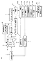
図1〜図3は、この発明を実施するための実施の形態1を示すものであり、図1は放射線モニタの構成を示す構成図、図2は動作を説明するための説明図、図3は動作を説明するためのフローチャートである。図1において、放射線検出器1は電荷積分部2に接続されている。放射線検出器1として、この実施の形態においては、電離箱を用いている。電荷積分部2は、コンデンサ2a及びオペアンプ2bを有する。オペアンプ2bの出力側が電圧比較部3及びアナログ/デジタル変換部7に接続されている。電圧比較部3の出力側が電荷放電部4及び矩形波パルス出力部5に接続されている。なお、電荷放電部4は定電流源4aを有する。矩形波パルス出力部5は、計数部6に接続され、計数部6の出力側は演算部10に接続されている。なお、この発明における鋸波状パルス生成部は、電荷積分部2、電圧比較部3、電荷放電部4にて構成されている。
1 to 3 show a first embodiment for carrying out the present invention. FIG. 1 is a configuration diagram showing the configuration of a radiation monitor, FIG. 2 is an explanatory diagram for explaining the operation, and FIG. Is a flowchart for explaining the operation. In FIG. 1, the
また、アナログ/デジタル変換部7の出力側が演算部10に接続されている。バイアス電源部8は演算部10から指令を受け放射線検出器1にバイアス電圧として例えば600〜800V程度の高電圧を供給する。温度測定部9は放射線検出器1及び電荷積分部2の近傍に配設されるとともに演算部10に接続され、温度に敏感な放射線検出器1及び電荷放電部4の周囲温度を測定して温度データを演算部10に送信する。演算部10は、計数率算出部10a、リーク電流補償部10b、工学値変換部10cを有し、これらの機能はマイクロコンピュータ上にて実行されるプログラムにて実現されている。演算部10は表示・操作部11と接続されている。表示部としての表示・操作部11は、演算部10から出力されたデータを表示すると共に、測定に必要な設定等の操作を行う。なお、これら放射線検出器1、電荷積分部2〜表示・操作部11は一つの箱に収容されている。
The output side of the analog /
次に、図2及び図3により動作を説明する。
電流信号を出力する放射線検出器1としては、電離箱、NaI(TI)シンチレーション検出器、プラスチックシンチレーション検出器等がある。アルミニウム容器に加圧したアルゴンまたは窒素あるいはそれらの混合ガスを封入した電離箱を使用することにより、バックグラウンド線量率レベルの10−14Aオーダの電離電流から、原子力発電所事故を想定した線量率レベルの10−7Aオーダの電離電流、すなわち約7デカードという広いレンジでかつエネルギー特性が良好(平坦)な線量率計が得られる。NaI(TI)シンチレーション検出器、プラスチックシンチレーション検出器は、検出器を構成する光電子増倍管の暗電流が10−9Aオーダと大きいためこの暗電流が無視できる高線量率領域の電流信号を測定するのに適する。
Next, the operation will be described with reference to FIGS.
Examples of the
一方、電離箱のリーク電流は、温度の上昇と共に増大し、例えばバックグラウンド線量率が50nGy/hの場合、常温から40℃に温度が上昇するとリーク電流により電流信号の1/4程度が消失しまうため、演算部10は、測定レンジ下限から2デカード程度上までの低線量率領域について、温度測定部9から出力された温度データに基づきリーク電流を補償する必要がある。高線量率領域の電流信号を測定するNaI(TI)シンチレーション検出器、プラスチックシンチレーション検出器も同様に、光電子増倍管の暗電流が無視できない領域では暗電流の補償が必要となる。以下、放射線検出器1としては、電離箱を代表として説明する。
On the other hand, the leakage current of the ionization chamber increases as the temperature rises. For example, when the background dose rate is 50 nGy / h, when the temperature rises from room temperature to 40 ° C., about 1/4 of the current signal disappears due to the leakage current. For this reason, the
電離箱の場合、矩形波パルス出力部5から出力される矩形波パルスの繰り返し周波数は、バックグラウンドレベルでは数cpmと低く分解能が低いため、精度の高い測定をしようとすると数10分間について計数する必要がある。そこで、以下のようにして測定時間を短縮する。演算部10は、アナログ/デジタル変換部7から出力された電圧データを入力し、電荷積分部2の鋸波状パルスのピーク電圧と谷電圧との電圧差を1カウントとみなし、今回演算周期に上記アナログ/デジタル変換部7から出力された設定時間経過時電圧値(デジタル変換された電圧データであり、設定時間経過時電圧値と記してデジタル値であることを明示する)p(n)に基づき1カウント未満の計数値c(n)を求め、計数部6から入力した計数値C(n)に加算して計数値C(n)+c(n)とし、前回演算周期のデジタルデータの1カウント未満の計数値c(n−1)を減算して、その差の{C(n)+c(n)}−c(n−1)に基づき今回の計数率N(n)を求めることにより、1カウント未満の計数を測定に使用して測定時間を短縮する。
In the case of an ionization chamber, the repetition frequency of the rectangular wave pulse output from the rectangular wave
以下、詳細に説明する。図2(a)において、放射線検出器1は放射線を検出して電流信号Jに変換して出力する。図2(b)において、電荷積分部2は電流信号Jを入力として電荷として蓄積し、蓄積された電荷に比例した電圧信号Vxを出力する。電圧比較部3は、その電圧信号Vxが設定された値Vaに到達したら反転してトリガ信号を発し、電荷放電部4によりトリガ信号をトリガにして定電流源4aから一定時間コンデンサ2aに当該コンデンサ2aに蓄積された電荷を打ち消す、つまり放電させるための電流が供給され、一定量の電荷の供給が終わるとコンデンサ2aに蓄積された一定量の電荷が放電され電圧信号Vxが所定の谷電圧になる。
Details will be described below. In FIG. 2A, the
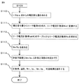
矩形波パルス出力部5は、上記トリガ信号に対応して一定電圧の、間隔が電流信号Jに反比例したワンショットパルスを出力する。このワンショットパルスは計数部6にて計数される。図3のステップS1において、設定された設定時間t0例えば短時間間隔2分が未だ経過していなければ最初へ戻り、電荷積分部2はコンデンサ2aに充放電を繰り返し(図2(b)参照)、設定時間が経過するまで鋸波状に変化する鋸波状パルスのパルス列が出力され、計数部6が矩形波パルス出力部5から出力されたワンショットパルスを計数する。つまり、計数部6は、鋸波状パルスの数あるいはトリガ信号の数を計数していることになる。ステップS1において、設定時間が経過すると、例えば測定開始から設定時間2分が経過すると、ステップS2へ行き、演算部10は計数部6から出力された計数値C(n)、設定時間経過時にアナログ/デジタル変換部7から出力された設定時間経過時電圧値p(n)(デジタル変換値)、温度データを読み込む。ステップS3において、演算部10は計数値C(n)と、設定時間経過時電圧値p(n)に基づき求めた1カウント未満の計数値c(n)を加算して計数値C(n)+c(n)とし、さらにこの計数値C(n)+c(n)を測定時間で除して計数率Nを演算する。なお、上記設定時間経過時電圧値p(n)は、電荷積分部2からアナログ/デジタル変換部7に入力された鋸波状パルスのアナログの電圧信号がアナログ/デジタル変換部7にてデジタル値に変換されたものである。
The rectangular wave
ステップS4において、演算部10のリーク電流補償部10bは、温度測定部9から入力された温度データに基づき、計数率算出部10aが算出した計数率Nを補償する。このステップS4の詳細は後述する。ステップS5において、工学値変換部10cは補償された計数率を線量率や放射能濃度等の工学値に変換し、表示・操作部11に表示する。以上で設定時間t0(例えば2分)を1サイクルとする放射線量の測定が終了する。ステップS6において、測定が終りでなければステップS1へ戻り再び測定を行い、測定が終りならば、動作を終了する。なお、放射線検出器1からの電流が極めて微弱で設定時間t0の間に鋸波状パルスが設定された値Vaに達しない場合は図2(b)に示すように、1カウント未満の計数となる。
In step S4, the leakage
次に、ステップS4における温度に対するリーク電流の補償について詳細に説明する。リーク電流は、測定レンジ下限から2デカード程度上までの低線量率領域の測定に影響する。演算部10のリーク電流補償部10bは、型式試験(後述)で測定して求めておいた、温度とリーク電流計数率との関係を示すリーク電流計数率のテーブルtab(Nc)または補償関数と、温度測定部9から出力された温度データとに基づき、当該温度におけるリーク電流計数率Ncを求め、測定された計数率Nに対してリーク電流分に相当するリーク電流計数率Ncを加算して補償する。型式試験において温度に対するリーク電流を測定するときは、電荷積分部2の出力にデジタルオシロを接続し、当該温度でバックグラウンドが安定した状態で、鋸波状パルスが谷電圧からピーク電圧に上昇する過程の中間に達したときのタイミングで、表示・操作部11を操作してバイアス電源部8の電圧設定を0Vにして、アナログ/デジタル変換部7から出力された電圧値の時間変化として測定する。なお、バイアス電源部8の電圧設定を0Vにすることにより、放射線検出器1からの入力電流が実質上入力されなくなるので、放射線検出器1からの本来の入力電流がゼロとなった時点からの電荷積分部2(コンデンサ2a)の電圧変化すなわちアナログ/デジタル変換部7から出力される電圧値の時間変化を測定することにより放射線検出器1が放射線を検出した結果としての本来の入力電流を除いたリーク電流を測定することができる。そして、このリーク電流をリーク電流計数率Ncに換算して、リーク電流計数率のテーブルtab(Nc)や補償関数を作成する。なお、放射線モニタ毎にリーク電流計数率のテーブルまたは補償関数を用意して補償し、器差を排除するようにしてもよい。
Next, the compensation of the leakage current with respect to the temperature in step S4 will be described in detail. Leakage current affects the measurement in the low dose rate region from the lower limit of the measurement range to about 2 decades. The leakage
以上のように、演算部10は、計数部6から出力される計数値C(n)とアナログ/デジタル変換部7から出力される設定時間経過時電圧値p(n)の両方に基づき計数率Nを演算し、すなわち設定時間経過時電圧値p(n)に基づく1カウント未満の計数を計数値に取り込んで計数率Nを求めることにより、環境放射線モニタリング指針(原子力安全委員会発行)の短時間間隔2分のデータ収集でも例えば1%以下の高精度で線量率を測定できるようになり、分解能を向上させかつ応答性を速めるように構成されている。加えて温度測定部9から出力された温度データに基づきリーク電流を求め、リーク電流に基づき計数率を補償することにより温度に対する安定性を向上させるようにしたので、ワイドレンジで高精度で応答性が速くかつ高安定の放射線モニタを得ることができる。
As described above, the
実施の形態2.
図4〜図6は、実施の形態2を示すものであり、図4は放射線モニタの構成を示す構成図、図5及び図6は動作を説明するためのフローチャートである。図4において、演算部20はリーク電流補償部20a及びリーク電流測定部20bを有する。演算部20の機能はマイクロコンピュータ上にて実行されるプログラムにて実現されている。表示部としての表示・操作部21は測定モード切換部としての選択ボタン21aを有する。その他の構成については、図1に示した実施の形態1と同様のものであるので、相当するものに同じ符号を付して説明を省略する。この実施の形態2は、実際の使用状態においてリーク電流を測定できるように演算部20にリーク電流測定部20bを設け、放射線検出器1から出力された電流信号を測定する通常測定モードと、バイアス電源部8の出力電圧を0Vにして電荷積分部2に入力されるリーク電流を測定するリーク電流測定モードと、を画面上で切り換える選択ボタン21aを表示・操作部21に設けたものである。
4 to 6 show the second embodiment, FIG. 4 is a configuration diagram showing the configuration of the radiation monitor, and FIGS. 5 and 6 are flowcharts for explaining the operation. In FIG. 4, the
表示・操作部21の選択ボタン21aによる選択操作により通常測定モードが選択されると、演算部20は、バイアス電源部8のバイアス電圧を制御し、放射線検出器1にバイアス電圧として所定の高電圧(600〜1000V程度)を印加する。一方、リーク電流測定モードが選択されると、バイアス電源部8はバイアス電圧を0Vにして放射線検出器1からの電流が実質的に入力されないようにリーク電流測定のための条件を整え、演算部20のリーク電流測定部20bは、実際のリーク電流を求め、求めたリーク電流をリーク電流計数率Nmに換算する。一方、温度データに基づき、内蔵するリーク電流計数率のテーブルtab(Nc)または補償関数から、リーク電流計数率Ncを求める。リーク電流計数率のテーブルtab(Nc)または補償関数は、実施の形態1で説明したものと同様のものである。そして、リーク電流測定モードにおいて測定されたリーク電流から求めたリーク電流計数率Nmとテーブルtab(Nc)または補償関数から求めたリーク電流計数率Ncとを比較し、その比が所定値内におさまっているか判定する。表示・操作部21には、リーク電流計数率Nm,Nc、計数率N(n)、リーク電流分を補償された計数率、温度、判定結果等を出力して表示する。
When the normal measurement mode is selected by the selection operation by the
次に、図5及び図6のフローチャートにより、選択ボタン21aによる切換操作と演算部20の制御・演算の詳細な手順について詳細に説明する。まず、図5のフローチャートにより、ステップS101からステップS109までの動作を説明する。通常測定モードにおいては、リーク電流補償部20aは実施の形態1におけるリーク電流補償部10bと同様に、型式試験で測定して求めておいた、温度とリーク電流計数率との関係を示すリーク電流計数率のテーブルtab(Nc)または補償関数と、温度測定部9から出力された温度データとに基づき、当該温度におけるリーク電流計数率Ncを求め、測定された計数率Nに対してリーク電流分に相当するリーク電流計数率Ncを加算して補償する。
Next, the detailed procedure of the switching operation by the
選択ボタン21aでリーク電流測定モードを選択し、通常測定モードからリーク電流測定モードに切り換えると、演算部20のリーク電流測定部20bは、ステップS101で鋸波状パルスの電圧データを読み込み、ステップS102で鋸波状パルスの電圧<1/2Vp−pかを判定し、NOならばステップS101に戻り、YESならば次の演算周期のステップS103で鋸波状パルスの電圧データを読み込む。ステップS104で鋸波状パルスの電圧≧1/2Vp−pかどうかを判定し、NOならばステップS103に戻る。YESならばステップS105でバイアス電源部8を高電圧出力が0Vになるように制御し、次の演算周期のステップS106で鋸波状パルスの電圧データを読み込む。
When the leakage current measurement mode is selected with the
ここに、Vp−pは、鋸波状パルスの谷電圧とピーク電圧との差電圧であり、1/2Vp−pはその中間点の電圧である。ステップS104、ステップS105にて鋸波状パルスの電圧が中間点の電圧1/2Vp−p以上になったら、バイアス電源部8からの高電圧出力を0Vに変更し、放射線検出器1からの電流が実質的に入力されないようにしてから、ステップS106以降のリーク電流の測定を開始する。このとき、放射線検出器1からの電流がなくなれば、リーク電流が全くなければ電圧の変化はなく電圧1/2Vp−pのまま保たれるが、リーク電流の影響がプラスあるいはマイナスに作用すれば電圧は1/2Vp−pを基点として増加あるいは減少することになる。この増加あるいは減少を見られるようにするために、スタートポイント中間点の電圧1/2Vp−pに設定しているが、厳密に1/2Vp−pに設定しなくても増加あるいは減少を測定することができるので、厳密に1/2Vp−pに設定する必要はない。
Here, Vp-p is a difference voltage between the valley voltage and the peak voltage of the sawtooth pulse, and 1/2 Vp-p is a voltage at the intermediate point. In step S104 and step S105, when the voltage of the sawtooth pulse becomes equal to or higher than the
ステップS107で電圧が所定の範囲内にあるか否かを判定し、NOならばステップS109へ飛び、YESならばステップS108へ進む。例えば、下限値は0.5V、上限値は放射線モニタの検出感度等で決められるが、例えば2.5Vに設定しておく。ステップS108では、電圧データの読み込み(ステップS106における読込)を予め決められた回数行ったかを判定し、NOならばステップS106に戻り、再び電圧データを読み込む。ステップS108で、YESならば次のステップS109で鋸波状パルスの電圧データ及び温度データを読み込む。このように予め決められた回数、電圧データを読み込んでから、さらにステップS109にて鋸波状パルスの電圧データ及び温度データを読み込みステップS110以降に進むのは、必要以上の頻度で判定を行わないようにするためである。また、ステップS107で鋸波状パルスの電圧が下限値あるいは上限値の範囲外となったときは、何らかの原因でリーク電流が急変したとして所定回数分の電圧データの読込動作を行わず、直ちにステップS109へ飛んで、以降の判定動作を行う。 In step S107, it is determined whether or not the voltage is within a predetermined range. If NO, the process jumps to step S109, and if YES, the process proceeds to step S108. For example, the lower limit value is set to 0.5 V, and the upper limit value is determined by the detection sensitivity of the radiation monitor, but is set to 2.5 V, for example. In step S108, it is determined whether the voltage data has been read (read in step S106) a predetermined number of times. If NO, the process returns to step S106, and the voltage data is read again. If YES in step S108, the voltage data and temperature data of the sawtooth pulse are read in the next step S109. The voltage data is read for a predetermined number of times as described above, and then the voltage data and temperature data of the sawtooth pulse are read in step S109 and the process proceeds to step S110 and subsequent steps so as not to make a determination more frequently than necessary. It is to make it. When the voltage of the sawtooth pulse goes out of the lower limit value or the upper limit value in step S107, it is assumed that the leakage current has suddenly changed for some reason, and the voltage data reading operation for a predetermined number of times is not performed, and step S109 is immediately performed. The following determination operation is performed.
次に、図6のフローチャートにより、ステップS110以降の動作を説明する。ステップS110で、1/2Vp−pの点からの電圧変化量を求め、ステップS111でその電圧変化量に相当する1カウント未満の電圧データを高電圧出力0Vに変更してからの時間で除してリーク電流(低下または増加)を求め、求めたリーク電流をリーク電流計数値Nmに変換する。一方、ステップS112で測定温度に基づきリーク電流計数率のテーブルtab(Nc)と照合して(または当該補償関数から計算して)リーク電流分に相当するリーク電流計数率Ncを求める。ステップS113でその比Nm/Ncを求め、ステップS114でNm/Ncが許容範囲内かを判定する。この許容範囲は、要求される測定精度等により決定される。ステップS115でリーク電流分を補償した計数率、実測したリーク電流から求めたリーク電流計数率Nm、テーブtab(Nc)から求めたリーク電流計数率Nc、その比Nm/Nc、判定結果等を表示・操作部21に表示して終了する。表示・操作部21でリーク電流の測定結果を確認したら、選択ボタン21aを押して、通常測定モードを選択してリーク電流測定モードから通常測定モードに切り換える。
Next, operations after step S110 will be described with reference to the flowchart of FIG. In step S110, the amount of voltage change from the point of 1/2 Vp-p is obtained, and in step S111, the voltage data less than 1 count corresponding to the voltage change amount is divided by the time after changing to the high voltage output 0V. Thus, the leak current (decrease or increase) is obtained, and the obtained leak current is converted into a leak current count value Nm. On the other hand, in step S112, the leak current count rate Nc corresponding to the leak current is obtained by collating with the table tab (Nc) of the leak current count rate based on the measured temperature (or calculating from the compensation function). In step S113, the ratio Nm / Nc is obtained. In step S114, it is determined whether Nm / Nc is within the allowable range. This allowable range is determined by required measurement accuracy and the like. The count rate compensated for the leak current in step S115, the leak current count rate Nm obtained from the actually measured leak current, the leak current count rate Nc obtained from the tab tab (Nc), the ratio Nm / Nc, the determination result, etc. are displayed. Display on the
なお、測定モードにおいてリーク電流計数値Ncの代わりにリーク電流測定モードにて測定したリーク電流計数値Nmを用いることもできる。この場合は、リーク電流測定モードのまま測定を継続し、演算部20におけるプログラムを変更して対応する。
Note that the leak current count value Nm measured in the leak current measurement mode may be used instead of the leak current count value Nc in the measurement mode. In this case, the measurement is continued in the leakage current measurement mode, and the program in the
以上のように、表示・操作部21に通常測定モードとリーク電流測定モードとを切り換える切換手段としての選択ボタン21aを設け、ワンタッチ操作により現在測定されたリーク電流に対応するリーク電流計数率Nmと、予めリーク電流計数率のテーブルに登録された当該温度におけるリーク電流分に相当するリーク電流計数率Nc(あるいは補償関数から求められたリーク電流計数率Nc)と、が比較判定され、それらと判定結果が表示・操作部21に表示されるようにしたので、運用後におけるリーク電流を補償する機能の健全性を容易にチェックできるという効果を奏する。
As described above, the display /
実施の形態3.
図7及び図8は、実施の形態3を示すものであり、図7は放射線モニタの構成を示す構成図、図8は動作を説明するためのフローチャートである。図7において、演算部30はゲイン補償部30aを有する。演算部30の機能はマイクロコンピュータ上にて実行されるプログラムにて実現されている。その他の構成については、図1に示した実施の形態1と同様のものであるので、相当するものに同じ符号を付して説明を省略する。この実施の形態3は、演算部30が、周囲温度に応じてリーク電流の影響を補償するとともに放射線検出器1から入力される電流信号を鋸波状パルスの繰り返し周波数に変換する変換率としてのゲインを温度に応じて補償するものである。このゲインは、電荷積分部2に用いられているコンデンサ2aや電荷放電部4の定電流源4aに用いられている放電方向を定めるダイオード(図示せず)等の温度特性により変化するものであり、この実施の形態ではこれらによるゲインの温度変化を含めて補償し、更なる測定精度の向上を図るものである。
7 and 8 show the third embodiment, FIG. 7 is a block diagram showing the configuration of the radiation monitor, and FIG. 8 is a flowchart for explaining the operation. In FIG. 7, the
まず、型式試験において、温度に対するリーク電流のテーブルtab(K)とゲイン温度補償係数のテーブルtab(R)を作成しておく。形式試験において、高電圧出力0Vの状態で温度を変化させてリーク電流を測定し、リーク電流のテーブルtab(K)を作成する。次に、基準電圧発生器を接続して本来の入力電流の代わりに基準電流を入力し、電荷積分部2の出力側にデジタルオシロを接続し、温度を変化させながらアナログ/デジタル変換部7から出力される電圧データに基づき鋸波状パルスのピーク電圧と谷電圧との電圧差Vp−pを求める。そして、この電圧差Vp−pを基準温度(例えば20℃)における同様の電圧差Vp−p(20℃)を基準にして各温度におけるゲイン変動率Gを求め、この逆数であるゲイン温度補償係数のテーブルtab(R)を作成しておく。あるいは、温度とゲイン温度補償計数Rとの関係を関数化した補償関数を作成しておく。そして、実際の測定時には、演算部30は、上記ゲイン温度補償係数のテーブルtab(R)または補償関数と、温度測定部9から出力された温度データとに基づき、計数率算出部10aが算出した計数率Nに当該周囲温度に対応するゲイン温度補償係数Rを乗じることで計数率のゲイン温度補償を行う。
First, in the type test, a leakage current table tab (K) and a gain temperature compensation coefficient table tab (R) are prepared. In the formal test, the leakage current is measured by changing the temperature in a state where the high voltage output is 0 V, and a leakage current table tab (K) is created. Next, a reference voltage generator is connected, a reference current is input instead of the original input current, a digital oscilloscope is connected to the output side of the
次に、補償手順の詳細について図8のフローチャートに基づき説明する。演算部30のゲイン補償部30aは、ステップS201で計数率算出部10aが算出した計数率Nと温度データを読み込み、ステップS202で周囲温度とゲイン温度補償係数のテーブルtab(R)に基づき測定温度におけるゲイン温度補償係数Rを求める。ステップS203においては、測定した計数率Nに上記求めたゲイン温度補償係数Rを乗じて上記基準温度(例えば20℃)における値に換算したゲイン温度補償計数率Naを求める。ステップS204でリーク電流補償部10bは温度とリーク電流のテーブルtab(K)により測定時の温度に対応したリーク電流Kを求め、ステップS205でリーク電流Kにゲイン温度補償係数Rを乗じて補正リーク電流係数率Nbを求める。ステップS206でゲイン温度補償計数率Naに補正リーク電流係数率Nbを加算してゲイン及びリーク電流の補償を行った計数率である出力係数率Ncを求めて、この出力係数率Ncを工学値に変換してステップS201へ戻る。
Next, details of the compensation procedure will be described based on the flowchart of FIG. The
以上のように、演算部30は、測定した温度に基づき、計数率についてゲインの温度特性を補償したゲイン温度補償計数率Naを求め、次にリーク電流についてもゲインの温度特性を補償した補正リーク電流計数率Nbを求め、ゲイン温度補償計数率Naに補正リーク電流係数率Nbを加算してリーク電流及びゲインの温度補償を行った計数率Ncを出力するようにしたので、温度に対するゲイン及びリーク電流の影響を軽減し、安定化を図ることができる。
As described above, the
なお、上記ではゲイン及びリーク電流の双方の補償を行うものを示したが、ゲインの温度補償だけを行ってもよい。どの程度の測定精度が必要とされるかにより、組み合わせを適宜行うことができる。 In the above description, compensation for both gain and leakage current is shown, but only gain temperature compensation may be performed. Combinations can be made as appropriate depending on how much measurement accuracy is required.
実施の形態4.
図9〜図11は、実施の形態4を示すものであり、図9は放射線モニタの構成を示す構成図、図10及び図11は動作を説明するためのフローチャートである。図9において、演算部40はゲイン補償部40a及びゲイン測定部40bを有する。表示部としての表示・操作部41は、測定モードを切り換えるゲイン補償測定モード切換部としての選択ボタン41aを有する。演算部40の機能はマイクロコンピュータにて実現されている。その他の構成については、図7に示した実施の形態3と同様のものであるので、相当するものに同じ符号を付して説明を省略する。この実施の形態4は、実施の形態3と同様に予め形式試験において求められた温度に対するゲイン温度補償係数のテーブルtab(R)から求めたゲイン温度補償係数Rを用いてゲイン補償部40aにより計数率を補償する通常のゲイン補償測定モードと、ゲイン測定部40bにて実際の測定の場において電荷積分部2から出力される鋸波状パルスの電圧に基づいて求められたゲイン温度補償係数を複数個平均して得られた平均ゲイン温度補償係数Raを用いてゲイン補償部40aにより計数率を補償する電圧差ゲイン補償測定モードと、を選択ボタン41aにより切り換えできるようにしたものである。
9 to 11 show the fourth embodiment. FIG. 9 is a block diagram showing the configuration of the radiation monitor, and FIGS. 10 and 11 are flowcharts for explaining the operation. In FIG. 9, the
次に動作について説明する。通常補正モードにおいては、実施の形態3と同様であり、ゲイン補償部40aがゲイン温度補償係数のテーブルtab(R)からゲイン温度補償係数Rを求めて計数率Nの補償を行う。選択ボタン41aにより実測ゲイン補償モード(電圧差ゲイン補償測定モード)が選択されると、以下に述べるような動作をする。演算部40のゲイン測定部40bが、アナログ/デジタル変換部7から出力される電圧値に基づき鋸波状パルスのピーク電圧と谷電圧との電圧差Vp−p(M)を実際に求め、この電圧差Vp−p(M)に基づいてゲインの温度変化を求めて、ゲイン補償部40aが計数率を補償できるようにしたものである。鋸波状パルスのピーク電圧と谷電圧は、電荷積分部2に用いられているコンデンサ2aや電荷放電部4の定電流源4aに用いられている放電方向を定めるダイオード(図示せず)等の温度特性により変化するものであり、結果としてゲインの温度変化をもたらす。例えば、谷電圧は、理想的には例えば0.5Vを基準としたら0.5Vで一定であるべきだが、定電流源4aやコンデンサ2aの特性の温度変化により、若干プラス電圧になったりマイナス電圧になったりする。この実施の形態ではこれら鋸波状パルスのピーク電圧と谷電圧の差電圧Vp−p(M)からゲインの温度変化を求めて補償し、一層の測定精度の向上を可能とするものである。
Next, the operation will be described. In the normal correction mode, the
この補償手順の詳細を図10及び図11のフローチャートに基づき説明する。なお、電圧値についてはいつの演算周期かを今回を(n)、前回を(n−1)、前々回を(n−2)にて表すことにする。まず、図10によりステップS301からステップS309までの動作を説明する。ステップS301で計数率、温度、今回の電圧値V(n)、前回の電圧値V(n−1)、前々回の電圧値V(n−2)を読み込み、ステップS302で計数率≦ゲイン補償上限計数率かを判定する。ステップS302で、YESならステップS303へ行く。このステップS302で計数率≦ゲイン補償上限計数率かを判定するのは、高計数率時は精度の高い測定よりも応答性が重要であり、ゲイン補償が求められるのは低計数率領域であるからである。 Details of this compensation procedure will be described with reference to the flowcharts of FIGS. As for the voltage value, this time (n), the previous time (n-1), and the last time (n-2) indicate the calculation period. First, the operation from step S301 to step S309 will be described with reference to FIG. In step S301, the count rate, temperature, current voltage value V (n), previous voltage value V (n-1), and previous voltage value V (n-2) are read. In step S302, count rate≤gain compensation upper limit. Judge whether the count rate. If YES in step S302, the process proceeds to step S303. In step S302, it is important to determine whether the count rate is equal to or less than the gain compensation upper limit count rate. When the count rate is high, responsiveness is more important than accurate measurement, and gain compensation is required in the low count rate region. Because.
ステップS303で電圧値V(n)<電圧値V(n−1)かどうかを判定し、YESならばステップS304へ行く。ステップS304で電圧値V(n)<電圧値V(n−2)かどうかを判定し、YESならステップS305へ行く。なお、ステップS303で電圧値V(n)<電圧値V(n−1)かどうかの判定と、ステップS304で電圧値V(n)<電圧値V(n−2)かの判定と、同種判定を2回行うようにしているが、これはノイズによる誤判定を防止して鋸波状パルスの増加から減少への反転に対応したピーク電圧を確実に測定するためである。ステップS305で電圧値V(n−1)を鋸波状パルスのピーク電圧とみなし、次の演算周期のステップS306で計数率、温度、電圧値V(n)を読み込む。このステップS306で演算周期を1回飛ばして鋸波状パルスの谷電圧を測定するようにしたのは、反転時のノイズを拾わないようにする念のための処置である。 In step S303, it is determined whether or not voltage value V (n) <voltage value V (n-1). If YES, the process proceeds to step S304. In step S304, it is determined whether or not voltage value V (n) <voltage value V (n-2). If YES, the process proceeds to step S305. It should be noted that the determination whether or not the voltage value V (n) <the voltage value V (n−1) in step S303 and the determination whether the voltage value V (n) <the voltage value V (n−2) in step S304 are the same. The determination is performed twice, in order to prevent erroneous determination due to noise and to reliably measure the peak voltage corresponding to the reversal from the increase of the sawtooth pulse to the decrease. In step S305, the voltage value V (n-1) is regarded as the peak voltage of the sawtooth pulse, and the count rate, temperature, and voltage value V (n) are read in step S306 of the next calculation cycle. The fact that the trough voltage of the sawtooth pulse is measured by skipping the calculation cycle once in step S306 is a measure to prevent picking up noise during inversion.
さらに、ステップS307で電圧値V(n)を鋸波状パルスの谷電圧とみなし、ステップS308でピーク電圧と谷電圧との電圧差Vp−p(M)を求める。ステップS309で予め型式試験において求められた基準温度(校正時の温度例えば20℃)におけるピーク電圧と谷電圧との電圧差をVp−p(S)とし、測定温度の電圧差をVp−p(M)とし、Vp−p(M)とVp−p(S)との比Vp−p(M)/Vp−p(S)を求めてその比を測定温度におけるゲイン変動率とし、その逆数のVp−p(S)/Vp−p(M)をゲイン補償係数Rとする。 Further, in step S307, the voltage value V (n) is regarded as the valley voltage of the sawtooth pulse, and in step S308, the voltage difference Vp−p (M) between the peak voltage and the valley voltage is obtained. In step S309, the voltage difference between the peak voltage and the valley voltage at the reference temperature (calibration temperature, for example, 20 ° C.) obtained in advance in the model test is Vp−p (S), and the voltage difference between the measured temperatures is Vp−p ( M), a ratio Vp-p (M) / Vp-p (S) between Vp-p (M) and Vp-p (S) is obtained, and the ratio is defined as a gain fluctuation rate at the measured temperature, Let Vp−p (S) / Vp−p (M) be the gain compensation coefficient R.
ステップS310で移動平均により直近の所定数のゲイン補償係数Rから平均ゲイン補償係数Raを求め、ステップS311で測定した計数率Nに平均ゲイン温度補償係数Raを乗じて基準温度に対応する補償計数率Neを求める。ステップS312で温度とリーク電流のテーブルtab(K)からリーク電流Kを求め、ステップS313でリーク電流Kに平均ゲイン温度補償係数Raを乗じて補正リーク電流計数率Nfを求める。ステップS314で補償計数率Neに補正リーク電流計数率Nfを加算して補償された出力計数率Ngを求めて出力し、ステップS301へ戻る。また、ステップS302、ステップS303、ステップS304でNOならばステップS301へ戻る。 In step S310, an average gain compensation coefficient Ra is obtained from a predetermined number of gain compensation coefficients R closest to the moving average, and the count rate N measured in step S311 is multiplied by the average gain temperature compensation coefficient Ra to obtain a compensation count rate corresponding to the reference temperature. Find Ne. In step S312, the leak current K is obtained from the temperature and leak current table tab (K), and in step S313, the leak current K is multiplied by the average gain temperature compensation coefficient Ra to obtain the corrected leak current count rate Nf. In step S314, the compensated leakage current count rate Nf is added to the compensation count rate Ne to obtain and output the compensated output count rate Ng, and the process returns to step S301. If NO in step S302, step S303, or step S304, the process returns to step S301.
以上のように、実際の使用状態における鋸波状パルスのピーク電圧と谷電圧の電圧差に基づいてゲインの温度変化による影響を補償するようにしたので、実施の形態3の効果に加えて経時的なゲイン変動も補償できる効果を奏する。 As described above, since the influence due to the temperature change of the gain is compensated based on the voltage difference between the peak voltage and the valley voltage of the sawtooth pulse in the actual use state, in addition to the effect of the third embodiment, It is effective in compensating for any gain fluctuations.
なお、本発明は、その発明の範囲内において、上述した各実施の形態を自由に組み合わせたり、各実施の形態を適宜、変更、省略することが可能である。 In the present invention, the above-described embodiments can be freely combined within the scope of the invention, or each embodiment can be appropriately changed or omitted.
1 放射線検出器、2 電荷積分部、2a コンデンサ、2b オペアンプ、
3 電圧比較部、4 電荷放電部、4a 定電流源、5 矩形波パルス出力部、
6 計数部、7 アナログ/デジタル変換部、9 温度測定部、10 演算部、
10a 計数率算出部、10b リーク電流補償部、11 表示・操作部、
20 演算部、20a リーク電流補償部、20b リーク電流測定部、
21 表示・操作部、21a 選択ボタン、30 演算部、30a ゲイン補償部、
40 演算部、40a ゲイン補償部、40b ゲイン測定部、41 表示・操作部、
41a 選択ボタン。
1 radiation detector, 2 charge integrator, 2a capacitor, 2b operational amplifier,
3 voltage comparison unit, 4 charge discharge unit, 4a constant current source, 5 rectangular wave pulse output unit,
6 counting section, 7 analog / digital converting section, 9 temperature measuring section, 10 calculating section,
10a Count rate calculation unit, 10b Leakage current compensation unit, 11 Display / operation unit,
20 calculation unit, 20a leakage current compensation unit, 20b leakage current measurement unit,
21 display / operation unit, 21a selection button, 30 calculation unit, 30a gain compensation unit,
40 calculation unit, 40a gain compensation unit, 40b gain measurement unit, 41 display / operation unit,
41a Selection button.
Claims (10)
上記放射線検出器は、放射線を検出して電流信号を出力するものであり、
上記鋸波状パルス生成部は、電荷積分部と電圧比較部と電荷放電部とを有し、
上記電荷積分部は、上記放射線検出器から入力された上記電流信号を電荷として蓄積し、蓄積された電荷に比例した電圧信号を出力するものであり、
上記電圧比較部は、上記電荷積分部が出力する上記電圧信号が設定された値に到達したらトリガ信号を出力するものであり、
上記電荷放電部は、上記トリガ信号をトリガにして上記電荷積分部に蓄積された電荷を放電させるものであり、
上記電荷積分部の上記電圧信号は上記電荷の蓄積と上記放電とを繰り返すことにより鋸波状に変化する鋸波状パルスとして出力されるものであり、
上記計数部は、設定時間当たりの上記トリガ信号の数を計数値N(n)として計数するものであり、
上記電圧検出部は、上記鋸波状パルスの電圧を検出するとともに上記設定時間経過時における上記鋸波状パルスの電圧値を設定時間経過時電圧として検出するものであり、
上記温度測定部は、上記放射線検出器及び上記鋸波状パルス生成部の少なくとも一方の周囲温度を温度データとして測定するものであり、
上記演算部は、計数率算出部とリーク電流補償部とを有し、
上記計数率算出部は、上記鋸波状パルスのピーク電圧と谷電圧との電圧差を1カウントとみなし、上記設定時間経過時電圧に基づいて1カウント未満の計数値p(n)を求め、上記計数値N(n)に加算してN(n)+p(n)を求め、前回の測定時に求めた1カウント未満の計数値p(n−1)を減算して、両者の差の{N(n)+p(n)}−p(n−1)に基づいて計数率を求めるものであり、
上記リーク電流補償部は、上記温度データに基づいてリーク電流を求め上記求められたリーク電流に基づいて上記計数率を補償するものであり、
上記バイアス電源部は、上記放射線検出器にバイアス電圧を供給して上記放射線を検出して上記電流信号を出力しうる状態にするものである
放射線モニタ。 A radiation monitor having a radiation detector, a sawtooth pulse generation unit, a counting unit, a voltage detection unit, a temperature measurement unit, a calculation unit, and a bias power supply unit,
The radiation detector detects radiation and outputs a current signal.
The sawtooth pulse generation unit has a charge integration unit, a voltage comparison unit, and a charge discharge unit,
The charge integration unit accumulates the current signal input from the radiation detector as a charge, and outputs a voltage signal proportional to the accumulated charge,
The voltage comparison unit outputs a trigger signal when the voltage signal output from the charge integration unit reaches a set value,
The charge discharge unit is for discharging the charge accumulated in the charge integration unit using the trigger signal as a trigger,
The voltage signal of the charge integrator is output as a sawtooth pulse that changes in a sawtooth shape by repeating the accumulation of the charge and the discharge.
The counting unit counts the number of the trigger signals per set time as a count value N (n) ,
The voltage detection unit detects a voltage of the sawtooth pulse and detects a voltage value of the sawtooth pulse when the set time has elapsed as a voltage when the set time has elapsed,
The temperature measurement unit measures the ambient temperature of at least one of the radiation detector and the sawtooth pulse generation unit as temperature data,
The calculation unit includes a count rate calculation unit and a leakage current compensation unit,
The count rate calculation unit regards the voltage difference between the peak voltage and the valley voltage of the sawtooth pulse as 1 count, obtains a count value p (n) less than 1 count based on the voltage when the set time has elapsed, N (n) + p (n) is obtained by adding to the count value N (n), and the count value p (n-1) less than 1 count obtained at the previous measurement is subtracted to obtain the difference {N (N) + p (n)} − p (n−1) is used to determine the count rate,
The leakage current compensator state, and are not to compensate for the count rate based on the sought leakage current determined leakage current based on the temperature data,
The bias power supply unit is a radiation monitor that supplies a bias voltage to the radiation detector to detect the radiation and output the current signal.
請求項1に記載の放射線モニタ。 The leakage current compensation unit obtains a leakage current at the time of measurement based on the temperature data and a relationship between a preset temperature and the leakage current, and compensates the count rate based on the leakage current at the time of measurement. is there
The radiation monitor according to claim 1 .
上記リーク電流測定部は、上記バイアス電源部を制御して上記バイアス電圧を0Vにして上記放射線検出器が上記電流信号を出力しえない状態にして上記鋸波状パルスの電圧変化量を測定することにより上記測定時におけるリーク電流を求めるものである
請求項1に記載の放射線モニタ。 A leakage current measurement unit is provided,
The leakage current measuring unit controls the bias power supply unit to set the bias voltage to 0 V and measure the voltage change amount of the sawtooth pulse in a state where the radiation detector cannot output the current signal. Is used to determine the leakage current during the above measurement.
The radiation monitor according to claim 1 .
上記測定モード切換部は、上記放射線検出器に上記バイアス電圧が印加された状態で上記電流信号を上記鋸波状パルス生成部に入力して測定を行う通常測定モードと、上記バイアス電圧を0Vにして上記電流信号が上記電荷積分部に入力されない状態にしてリーク電流を測定するリーク電流測定モードとを切り換えるものである
請求項1または請求項2に記載の放射線モニタ。 A measurement mode switching unit is provided,
The measurement mode switching unit includes a normal measurement mode in which the current signal is input to the sawtooth pulse generation unit in a state where the bias voltage is applied to the radiation detector, and the bias voltage is set to 0V. The radiation monitor according to claim 1 or 2 , wherein the current signal is switched to a leak current measurement mode in which a leak current is measured in a state where the current signal is not input to the charge integration unit.
上記ゲイン補償部は、上記電流信号を上記鋸波状パルスの繰り返し周波数に変換する変換率としてのゲインについて、上記温度データに基づいて測定時における上記ゲインを求め、測定時における上記ゲインに基づいて上記計数率を補償するものである
請求項1から請求項4のいずれか1項に記載の放射線モニタ。 The calculation unit includes a gain compensation unit,
The gain compensation unit obtains the gain at the time of measurement based on the temperature data for the gain as a conversion rate for converting the current signal into the repetition frequency of the sawtooth pulse, and the gain based on the gain at the time of measurement. The radiation monitor according to any one of claims 1 to 4 , which compensates the counting rate.
請求項5に記載の放射線モニタ。 The gain compensation unit obtains the gain at the time of measurement based on the temperature data and a relationship between a preset temperature and the gain.
The radiation monitor according to claim 5 .
請求項5に記載の放射線モニタ。 The gain compensation unit obtains the gain at the time of measurement based on the temperature data and a voltage difference between a peak voltage and a valley voltage of the sawtooth pulse.
The radiation monitor according to claim 5 .
上記ゲイン補償測定モード切換部は、上記ゲイン補償部が上記温度データ及び予め設定された温度と上記ゲインとの関係に基づいて測定時における上記ゲインを求める通常のゲイン補償測定モードと、上記ゲイン補償部が上記温度データ及び上記鋸波状パルスのピーク電圧と谷電圧との電圧差に基づいて測定時における上記ゲインを求める電圧差ゲイン補償測定モードとを切り換えるものである請求項5に記載の放射線モニタ。 A gain compensation measurement mode switching unit is provided,
The gain compensation measurement mode switching unit includes a normal gain compensation measurement mode in which the gain compensation unit obtains the gain at the time of measurement based on the temperature data and a relationship between a preset temperature and the gain, and the gain compensation 6. The radiation monitor according to claim 5 , wherein the unit switches a voltage difference gain compensation measurement mode for obtaining the gain at the time of measurement based on the temperature data and a voltage difference between a peak voltage and a valley voltage of the sawtooth pulse. .
上記放射線検出器は、放射線を検出して電流信号を出力するものであり、
上記鋸波状パルス生成部は、電荷積分部と電圧比較部と電荷放電部とを有し、
上記電荷積分部は、上記放射線検出器から入力された上記電流信号を電荷として蓄積し、蓄積された電荷に比例した電圧信号を出力するものであり、
上記電圧比較部は、上記電荷積分部が出力する上記電圧信号が設定された値に到達したらトリガ信号を出力するものであり、
上記電荷放電部は、上記トリガ信号をトリガにして上記電荷積分部に蓄積された電荷を放電させるものであり、
上記電荷積分部の上記電圧信号は上記電荷の蓄積と上記放電とを繰り返すことにより鋸波状に変化する鋸波状パルスとして出力されるものであり、
上記計数部は、設定時間当たりの上記トリガ信号の数を計数値として計数するものであり、
上記電圧検出部は、上記設定時間経過時における上記鋸波状パルスの電圧値を設定時間経過時電圧として検出するものであり、
上記温度測定部は、上記放射線検出器及び上記鋸波状パルス生成部の少なくとも一方の周囲温度を温度データとして測定するものであり、
上記演算部は、計数率算出部とリーク電流補償部とゲイン補償部とを有し、
上記計数率算出部は、上記計数値及び上記設定時間経過時電圧に基づいて計数率を求めるものであり、
上記リーク電流補償部は、上記温度データに基づいてリーク電流を求め上記求められたリーク電流に基づいて上記計数率を補償するものであり、
上記ゲイン補償部は、上記電流信号を上記鋸波状パルスの繰り返し周波数に変換する変換率としてのゲインについて、上記温度データ及び上記鋸波状パルスのピーク電圧と谷電圧との電圧差に基づいて測定時における上記ゲインを求め、測定時における上記ゲインに基づいて上記計数率を補償するものであり、
上記バイアス電源部は、上記放射線検出器にバイアス電圧を供給して上記放射線を検出して上記電流信号を出力しうる状態にするものである
放射線モニタ。 A radiation monitor having a radiation detector, a sawtooth pulse generation unit, a counting unit, a voltage detection unit, a temperature measurement unit, a calculation unit, and a bias power supply unit,
The radiation detector detects radiation and outputs a current signal.
The sawtooth pulse generation unit has a charge integration unit, a voltage comparison unit, and a charge discharge unit,
The charge integration unit accumulates the current signal input from the radiation detector as a charge, and outputs a voltage signal proportional to the accumulated charge,
The voltage comparison unit outputs a trigger signal when the voltage signal output from the charge integration unit reaches a set value,
The charge discharge unit is for discharging the charge accumulated in the charge integration unit using the trigger signal as a trigger,
The voltage signal of the charge integrator is output as a sawtooth pulse that changes in a sawtooth shape by repeating the accumulation of the charge and the discharge.
The counting unit counts the number of trigger signals per set time as a count value,
The voltage detector detects the voltage value of the sawtooth pulse when the set time has elapsed as a voltage when the set time has elapsed,
The temperature measurement unit measures the ambient temperature of at least one of the radiation detector and the sawtooth pulse generation unit as temperature data,
The calculation unit includes a count rate calculation unit, a leakage current compensation unit, and a gain compensation unit ,
The counting rate calculation unit obtains a counting rate based on the count value and the set time elapsed voltage,
The leakage current compensator state, and are not to compensate for the count rate based on the sought leakage current determined leakage current based on the temperature data,
The gain compensator measures a gain as a conversion rate for converting the current signal into the repetition frequency of the sawtooth pulse based on the temperature data and a voltage difference between a peak voltage and a valley voltage of the sawtooth pulse. The above-mentioned gain is obtained, and the counting rate is compensated based on the gain at the time of measurement,
The bias power supply unit is a radiation monitor that supplies a bias voltage to the radiation detector to detect the radiation and output the current signal.
上記放射線検出器は、放射線を検出して電流信号を出力するものであり、
上記鋸波状パルス生成部は、電荷積分部と電圧比較部と電荷放電部とを有し、
上記電荷積分部は、上記放射線検出器から入力された上記電流信号を電荷として蓄積し、蓄積された電荷に比例した電圧信号を出力するものであり、
上記電圧比較部は、上記電荷積分部が出力する上記電圧信号が設定された値に到達したらトリガ信号を出力するものであり、
上記電荷放電部は、上記トリガ信号をトリガにして上記電荷積分部に蓄積された電荷を放電させるものであり、
上記電荷積分部の上記電圧信号は上記電荷の蓄積と上記放電とを繰り返すことにより鋸波状に変化する鋸波状パルスとして出力されるものであり、
上記計数部は、設定時間当たりの上記トリガ信号の数を計数値として計数するものであり、
上記電圧検出部は、上記設定時間経過時における上記鋸波状パルスの電圧値を設定時間経過時電圧として検出するものであり、
上記温度測定部は、上記放射線検出器及び上記鋸波状パルス生成部の少なくとも一方の周囲温度を温度データとして測定するものであり、
上記演算部は、計数率算出部とリーク電流補償部とゲイン補償部とを有し、
上記計数率算出部は、上記計数値及び上記設定時間経過時電圧に基づいて計数率を求めるものであり、
上記リーク電流補償部は、上記温度データに基づいてリーク電流を求め上記求められたリーク電流に基づいて上記計数率を補償するものであり、
上記ゲイン補償部は、上記電流信号を上記鋸波状パルスの繰り返し周波数に変換する変換率としてのゲインについて、上記温度データに基づいて測定時における上記ゲインを求め、測定時における上記ゲインに基づいて上記計数率を補償するものであり、
上記ゲイン補償測定モード切換部は、上記ゲイン補償部が上記温度データ及び予め設定された温度と上記ゲインとの関係に基づいて測定時における上記ゲインを求める通常のゲイン補償測定モードと、上記ゲイン補償部が上記温度データ及び上記鋸波状パルスのピーク電圧と谷電圧との電圧差に基づいて測定時における上記ゲインを求める電圧差ゲイン補償測定モードとを切り換えるものであり、
上記バイアス電源部は、上記放射線検出器にバイアス電圧を供給して上記放射線を検出して上記電流信号を出力しうる状態にするものである
放射線モニタ。 A radiation monitor having a radiation detector, a sawtooth pulse generation unit, a counting unit, a voltage detection unit, a temperature measurement unit, a calculation unit, a gain compensation measurement mode switching unit, and a bias power supply unit,
The radiation detector detects radiation and outputs a current signal.
The sawtooth pulse generation unit has a charge integration unit, a voltage comparison unit, and a charge discharge unit,
The charge integration unit accumulates the current signal input from the radiation detector as a charge, and outputs a voltage signal proportional to the accumulated charge,
The voltage comparison unit outputs a trigger signal when the voltage signal output from the charge integration unit reaches a set value,
The charge discharge unit is for discharging the charge accumulated in the charge integration unit using the trigger signal as a trigger,
The voltage signal of the charge integrator is output as a sawtooth pulse that changes in a sawtooth shape by repeating the accumulation of the charge and the discharge.
The counting unit counts the number of trigger signals per set time as a count value,
The voltage detector detects the voltage value of the sawtooth pulse when the set time has elapsed as a voltage when the set time has elapsed,
The temperature measurement unit measures the ambient temperature of at least one of the radiation detector and the sawtooth pulse generation unit as temperature data,
The calculation unit includes a count rate calculation unit, a leakage current compensation unit, and a gain compensation unit ,
The counting rate calculation unit obtains a counting rate based on the count value and the set time elapsed voltage,
The leakage current compensator state, and are not to compensate for the count rate based on the sought leakage current determined leakage current based on the temperature data,
The gain compensation unit obtains the gain at the time of measurement based on the temperature data for the gain as a conversion rate for converting the current signal into the repetition frequency of the sawtooth pulse, and the gain based on the gain at the time of measurement. To compensate the counting rate,
The gain compensation measurement mode switching unit includes a normal gain compensation measurement mode in which the gain compensation unit obtains the gain at the time of measurement based on the temperature data and a relationship between a preset temperature and the gain, and the gain compensation The part switches the voltage difference gain compensation measurement mode for obtaining the gain at the time of measurement based on the temperature data and the voltage difference between the peak voltage and the valley voltage of the sawtooth pulse,
The bias power supply unit is a radiation monitor that supplies a bias voltage to the radiation detector to detect the radiation and output the current signal.
Priority Applications (1)
| Application Number | Priority Date | Filing Date | Title |
|---|---|---|---|
| JP2012266413A JP6076062B2 (en) | 2012-12-05 | 2012-12-05 | Radiation monitor |
Applications Claiming Priority (1)
| Application Number | Priority Date | Filing Date | Title |
|---|---|---|---|
| JP2012266413A JP6076062B2 (en) | 2012-12-05 | 2012-12-05 | Radiation monitor |
Publications (3)
| Publication Number | Publication Date |
|---|---|
| JP2014112052A JP2014112052A (en) | 2014-06-19 |
| JP2014112052A5 JP2014112052A5 (en) | 2015-12-03 |
| JP6076062B2 true JP6076062B2 (en) | 2017-02-08 |
Family
ID=51169281
Family Applications (1)
| Application Number | Title | Priority Date | Filing Date |
|---|---|---|---|
| JP2012266413A Active JP6076062B2 (en) | 2012-12-05 | 2012-12-05 | Radiation monitor |
Country Status (1)
| Country | Link |
|---|---|
| JP (1) | JP6076062B2 (en) |
Families Citing this family (7)
| Publication number | Priority date | Publication date | Assignee | Title |
|---|---|---|---|---|
| JP6331941B2 (en) * | 2014-10-03 | 2018-05-30 | 富士電機株式会社 | Current measuring device |
| JP6308934B2 (en) * | 2014-12-15 | 2018-04-11 | 三菱電機株式会社 | Radiation measurement equipment |
| WO2016170566A1 (en) * | 2015-04-20 | 2016-10-27 | 三菱電機株式会社 | Radiation measurement device |
| JP6628701B2 (en) * | 2016-08-05 | 2020-01-15 | 三菱電機株式会社 | Radiation measuring device |
| JP7027963B2 (en) * | 2018-03-02 | 2022-03-02 | 富士電機株式会社 | Current measuring device and radiation detection device |
| CN109471154B (en) * | 2018-11-09 | 2020-03-17 | 中国核动力研究设计院 | Small-size GM count pipe wide range monitoring instrument |
| JP7403488B2 (en) | 2021-02-18 | 2023-12-22 | 三菱電機株式会社 | Current signal processing device |
Family Cites Families (6)
| Publication number | Priority date | Publication date | Assignee | Title |
|---|---|---|---|---|
| JPS6183967A (en) * | 1984-09-29 | 1986-04-28 | Toshiba Corp | Apparatus for measuring minute current |
| JP2002365317A (en) * | 2001-06-11 | 2002-12-18 | Aloka Co Ltd | Electrometer circuit for ionization chamber |
| JP3863132B2 (en) * | 2003-08-29 | 2006-12-27 | 三菱電機株式会社 | Environmental radiation monitor |
| JP4227543B2 (en) * | 2004-03-10 | 2009-02-18 | アロカ株式会社 | Ionization chamber type radiation measuring device |
| JP4479430B2 (en) * | 2004-09-10 | 2010-06-09 | 富士電機システムズ株式会社 | Ultra-small current / frequency converter |
| JP4731330B2 (en) * | 2006-01-05 | 2011-07-20 | 三菱電機株式会社 | Radiation monitor |
-
2012
- 2012-12-05 JP JP2012266413A patent/JP6076062B2/en active Active
Also Published As
| Publication number | Publication date |
|---|---|
| JP2014112052A (en) | 2014-06-19 |
Similar Documents
| Publication | Publication Date | Title |
|---|---|---|
| JP6076062B2 (en) | Radiation monitor | |
| US8315836B2 (en) | Radiation measuring device and diagnostic method thereof | |
| JP4731330B2 (en) | Radiation monitor | |
| JP2014112052A5 (en) | ||
| JP5171891B2 (en) | Radiation measurement equipment | |
| JP2007183118A5 (en) | ||
| JP6218941B2 (en) | Radiation measurement equipment | |
| JP2014211381A (en) | Dose rate measurement device | |
| US6664777B2 (en) | Photometric apparatus and photometric method | |
| JP6643270B2 (en) | Photo detector | |
| JP5931690B2 (en) | Radiation measurement equipment | |
| JP5743844B2 (en) | Radiation monitor | |
| JP2006029986A (en) | Radiation measuring device | |
| US11041964B2 (en) | Radiation monitoring equipment | |
| JP6308934B2 (en) | Radiation measurement equipment | |
| RU75035U1 (en) | DEVICE FOR MEASURING VIBRATION VIBRATION PARAMETERS | |
| JP2001056380A (en) | Radiation monitor for measurement of counting rate | |
| JP4793044B2 (en) | Radiation detector | |
| JP2013072675A (en) | Radiation monitor | |
| JP5001899B2 (en) | Radiation measurement equipment | |
| JP2012007899A (en) | Radiation measurement apparatus | |
| JP4536668B2 (en) | Radioactive gas monitor | |
| RU2195029C2 (en) | Digital reactimeter | |
| SU1166026A1 (en) | Radiometric detection unit | |
| Vora et al. | A new approach to the direct digitization of low current |
Legal Events
| Date | Code | Title | Description |
|---|---|---|---|
| A521 | Request for written amendment filed |
Free format text: JAPANESE INTERMEDIATE CODE: A523 Effective date: 20151019 |
|
| A621 | Written request for application examination |
Free format text: JAPANESE INTERMEDIATE CODE: A621 Effective date: 20151019 |
|
| A131 | Notification of reasons for refusal |
Free format text: JAPANESE INTERMEDIATE CODE: A131 Effective date: 20160705 |
|
| A521 | Request for written amendment filed |
Free format text: JAPANESE INTERMEDIATE CODE: A523 Effective date: 20160902 |
|
| TRDD | Decision of grant or rejection written | ||
| A01 | Written decision to grant a patent or to grant a registration (utility model) |
Free format text: JAPANESE INTERMEDIATE CODE: A01 Effective date: 20161213 |
|
| A61 | First payment of annual fees (during grant procedure) |
Free format text: JAPANESE INTERMEDIATE CODE: A61 Effective date: 20170110 |
|
| R150 | Certificate of patent or registration of utility model |
Ref document number: 6076062 Country of ref document: JP Free format text: JAPANESE INTERMEDIATE CODE: R150 |
|
| R250 | Receipt of annual fees |
Free format text: JAPANESE INTERMEDIATE CODE: R250 |
|
| R250 | Receipt of annual fees |
Free format text: JAPANESE INTERMEDIATE CODE: R250 |
|
| R250 | Receipt of annual fees |
Free format text: JAPANESE INTERMEDIATE CODE: R250 |
|
| R250 | Receipt of annual fees |
Free format text: JAPANESE INTERMEDIATE CODE: R250 |
|
| R250 | Receipt of annual fees |
Free format text: JAPANESE INTERMEDIATE CODE: R250 |