JP6074368B2 - Underwater connector device - Google Patents
Underwater connector device Download PDFInfo
- Publication number
- JP6074368B2 JP6074368B2 JP2013553966A JP2013553966A JP6074368B2 JP 6074368 B2 JP6074368 B2 JP 6074368B2 JP 2013553966 A JP2013553966 A JP 2013553966A JP 2013553966 A JP2013553966 A JP 2013553966A JP 6074368 B2 JP6074368 B2 JP 6074368B2
- Authority
- JP
- Japan
- Prior art keywords
- component
- connector device
- coil antenna
- underwater
- submersible
- Prior art date
- Legal status (The legal status is an assumption and is not a legal conclusion. Google has not performed a legal analysis and makes no representation as to the accuracy of the status listed.)
- Active
Links
- 230000006854 communication Effects 0.000 claims description 42
- 238000004891 communication Methods 0.000 claims description 42
- 230000005540 biological transmission Effects 0.000 claims description 39
- 239000008393 encapsulating agent Substances 0.000 claims description 17
- XLYOFNOQVPJJNP-UHFFFAOYSA-N water Substances O XLYOFNOQVPJJNP-UHFFFAOYSA-N 0.000 claims description 16
- 238000000034 method Methods 0.000 claims description 11
- 230000008878 coupling Effects 0.000 claims description 9
- 238000010168 coupling process Methods 0.000 claims description 9
- 238000005859 coupling reaction Methods 0.000 claims description 9
- 238000005538 encapsulation Methods 0.000 claims description 7
- 230000003287 optical effect Effects 0.000 claims description 7
- 230000001939 inductive effect Effects 0.000 claims description 5
- 239000002775 capsule Substances 0.000 claims 4
- 238000012546 transfer Methods 0.000 description 9
- 238000004804 winding Methods 0.000 description 9
- 238000007689 inspection Methods 0.000 description 6
- 230000007246 mechanism Effects 0.000 description 6
- 238000004519 manufacturing process Methods 0.000 description 5
- 239000000463 material Substances 0.000 description 5
- 238000012545 processing Methods 0.000 description 5
- 230000005855 radiation Effects 0.000 description 5
- 239000013535 sea water Substances 0.000 description 5
- 238000005516 engineering process Methods 0.000 description 4
- 238000012423 maintenance Methods 0.000 description 4
- 230000008901 benefit Effects 0.000 description 3
- 239000004020 conductor Substances 0.000 description 3
- 150000003839 salts Chemical class 0.000 description 3
- 239000000969 carrier Substances 0.000 description 2
- 238000010586 diagram Methods 0.000 description 2
- 238000009826 distribution Methods 0.000 description 2
- 230000005670 electromagnetic radiation Effects 0.000 description 2
- 230000001965 increasing effect Effects 0.000 description 2
- 238000012544 monitoring process Methods 0.000 description 2
- 230000035699 permeability Effects 0.000 description 2
- 239000004033 plastic Substances 0.000 description 2
- 229920003023 plastic Polymers 0.000 description 2
- 230000010287 polarization Effects 0.000 description 2
- 238000004382 potting Methods 0.000 description 2
- 230000001902 propagating effect Effects 0.000 description 2
- 238000000926 separation method Methods 0.000 description 2
- 230000008054 signal transmission Effects 0.000 description 2
- 241000220010 Rhode Species 0.000 description 1
- VYPSYNLAJGMNEJ-UHFFFAOYSA-N Silicium dioxide Chemical compound O=[Si]=O VYPSYNLAJGMNEJ-UHFFFAOYSA-N 0.000 description 1
- 238000010521 absorption reaction Methods 0.000 description 1
- 230000007175 bidirectional communication Effects 0.000 description 1
- 230000004071 biological effect Effects 0.000 description 1
- 230000015572 biosynthetic process Effects 0.000 description 1
- 239000003990 capacitor Substances 0.000 description 1
- 230000000295 complement effect Effects 0.000 description 1
- 230000003750 conditioning effect Effects 0.000 description 1
- 230000001066 destructive effect Effects 0.000 description 1
- 230000001627 detrimental effect Effects 0.000 description 1
- 238000005553 drilling Methods 0.000 description 1
- 239000003822 epoxy resin Substances 0.000 description 1
- 239000000835 fiber Substances 0.000 description 1
- 230000004907 flux Effects 0.000 description 1
- 230000014509 gene expression Effects 0.000 description 1
- 238000003384 imaging method Methods 0.000 description 1
- 230000001976 improved effect Effects 0.000 description 1
- 238000005259 measurement Methods 0.000 description 1
- 239000002184 metal Substances 0.000 description 1
- 239000007769 metal material Substances 0.000 description 1
- 238000012986 modification Methods 0.000 description 1
- 230000004048 modification Effects 0.000 description 1
- 238000000465 moulding Methods 0.000 description 1
- 239000002245 particle Substances 0.000 description 1
- 229920000647 polyepoxide Polymers 0.000 description 1
- 229920000642 polymer Polymers 0.000 description 1
- 229920002635 polyurethane Polymers 0.000 description 1
- 239000004814 polyurethane Substances 0.000 description 1
- 230000008439 repair process Effects 0.000 description 1
- 229920002379 silicone rubber Polymers 0.000 description 1
- 239000004945 silicone rubber Substances 0.000 description 1
- 238000001228 spectrum Methods 0.000 description 1
- 230000008093 supporting effect Effects 0.000 description 1
- 230000002195 synergetic effect Effects 0.000 description 1
Images


Classifications
-
- H—ELECTRICITY
- H01—ELECTRIC ELEMENTS
- H01Q—ANTENNAS, i.e. RADIO AERIALS
- H01Q1/00—Details of, or arrangements associated with, antennas
- H01Q1/04—Adaptation for subterranean or subaqueous use
-
- H—ELECTRICITY
- H01—ELECTRIC ELEMENTS
- H01Q—ANTENNAS, i.e. RADIO AERIALS
- H01Q1/00—Details of, or arrangements associated with, antennas
- H01Q1/12—Supports; Mounting means
- H01Q1/22—Supports; Mounting means by structural association with other equipment or articles
- H01Q1/2291—Supports; Mounting means by structural association with other equipment or articles used in bluetooth or WI-FI devices of Wireless Local Area Networks [WLAN]
-
- H—ELECTRICITY
- H04—ELECTRIC COMMUNICATION TECHNIQUE
- H04B—TRANSMISSION
- H04B13/00—Transmission systems characterised by the medium used for transmission, not provided for in groups H04B3/00 - H04B11/00
- H04B13/02—Transmission systems in which the medium consists of the earth or a large mass of water thereon, e.g. earth telegraphy
-
- H04B5/22—
-
- H04B5/24—
-
- H04B5/72—
-
- H04B5/79—
Landscapes
- Engineering & Computer Science (AREA)
- Computer Networks & Wireless Communication (AREA)
- Signal Processing (AREA)
- Near-Field Transmission Systems (AREA)
- Arrangements For Transmission Of Measured Signals (AREA)
- Details Of Connecting Devices For Male And Female Coupling (AREA)
Description
本発明は、水中コネクタ装置に関し、例えば水中にある2つの物体間で物理的接続を必ずしも必要としなくても、広帯域幅信号伝送を提供するように動作可能である水中コネクタ装置に関する。さらに、本発明は、水中コネクタ装置を経由して広帯域幅信号を伝送する方法にも関する。 The present invention relates to an underwater connector device, for example, an underwater connector device that is operable to provide high bandwidth signal transmission without necessarily requiring a physical connection between two objects in the water. The invention further relates to a method for transmitting a wide bandwidth signal via an underwater connector device.
例えば、石油およびガスと関連した海洋探査および生産、ならびに海洋波、海流および海洋温度差(海洋熱エネルギ発電)から電力を発生させる再生可能エネルギシステムと関連して、海洋環境の内部で技術的装置を展開させる傾向が増大している。中東、米国の陸上および北大西洋で石油およびガスの埋蔵量が減少すると、石油およびガス会社は、大部分が陸地でなく氷床で覆われた地球の極地で石油およびガスをボーリングし採取することを考慮することになった。さらに、極地に接近する高緯度地帯には、海洋波エネルギ生産のためにもっとも有利な条件がある。このような上述した環境は過酷であり、技術的装置が故障すると、対処するのがコスト高となりうる。さらに、海洋の塩水は腐食性および導電性が高く、海底で接続するのは困難なことになる。このように導体間の直接の物理的接続が、ケーブルを接続する直接的な方法である限り、物理的接続は、水中で用いられるとき、特に水中で何度も、ケーブルを接離する必要があるとき、特に困難に直面する。これは、密封の完全性に有害な影響が生じ、それゆえ水が浸入する危険にさらされる可能性があるからである。物理的接続はまた、正確に整列させることが難しい場合があり、きつい湾曲に適用させるためには一層難しい。 Technical equipment within the marine environment, for example, in connection with ocean exploration and production associated with oil and gas, and renewable energy systems that generate power from ocean waves, ocean currents and ocean temperature differences (ocean thermal energy generation) There is an increasing tendency to deploy. As oil and gas reserves decrease in the Middle East, onshore USA and in the North Atlantic, oil and gas companies will drill and extract oil and gas at the Earth's polar regions, mostly covered with ice sheets rather than land. Would be considered. In addition, high latitudes approaching the polar regions have the most advantageous conditions for ocean wave energy production. Such an environment described above is harsh and can be costly to deal with if a technical device fails. In addition, marine salt water is highly corrosive and conductive, making it difficult to connect at the sea floor. So long as the direct physical connection between the conductors is a direct way of connecting the cables, the physical connection needs to be connected and disconnected many times, especially when used in water. At times, you will face particularly difficulties. This is because it can have a detrimental effect on the integrity of the seal and can therefore be at risk of water ingress. Physical connections can also be difficult to align accurately and are more difficult to apply to tight bends.
コネクタにおける電力の誘導伝送は、英国特許出願公開第2456039A号明細書(Rhodes&Hyland、「Multimode wireless communication system(マルチモード無線通信システム)」、Wireless Fibre Systems Ltd.)に記載されており、光、無線および音響搬送波から成る3つのメカニズムを、3つの搬送波のうちのもっとも適切なものを選択する選択装置と組み合わせて、動作可能に使用するマルチモードシステムが記載されている。この特許出願に関連した調査報告は、多数の先願:英国特許出願公開第2297667A号明細書、欧州特許出願公開第1370014A2号明細書、欧州特許出願公開第0338765A2号明細書、国際公開第02/071657A2号パンフレット、米国特許出願公開第2002/0067531A1号明細書、米国特許第5081543A号明細書を特定している。 Inductive transmission of power in the connector is described in GB 2456039A (Rhodes & Hyland, `` Multimode wireless communication system '', Wireless Fiber Systems Ltd.). A multi-mode system is described that operatively combines three mechanisms consisting of acoustic carriers with a selection device that selects the most appropriate of the three carriers. Search reports related to this patent application include a number of prior applications: British Patent Application Publication No. 2297667A, European Patent Application Publication No. 1370014A2, European Patent Application Publication No. 0338765A2, International Publication No. No. 071657A2, US Patent Application Publication No. 2002 / 0067531A1, and US Pat. No. 5,081,543A are specified.
無線周波数(RF:radio frequency)信号を用いた、より長い範囲にわたる水中通信も提案されている。例えば、米国特許出願公開第2009/0212969号明細書には、RF信号を用いて坑口装置とアンビリカル終端との間を通信するシステムが記載されている。 Long-range underwater communications using radio frequency (RF) signals have also been proposed. For example, US Patent Application Publication No. 2009/0212969 describes a system that communicates between a wellhead device and an umbilical end using an RF signal.
今まで複数の提案がなされているにもかかわらず、これらの提案は商業的に幅広く受け入れられるまでには達していなかったが、本出願人は、先行する提案に関していくつかの重要な欠点が存在することを認識していた。このような欠点に少なくとも部分的に対処し、商業的に魅力的な水中コネクタシステムを提供することが、本発明の目的である。 Although several proposals have been made so far, these proposals have not yet reached wide commercial acceptance, but the applicant has some important drawbacks with respect to the previous proposal. Recognized to do. It is an object of the present invention to at least partially address such shortcomings and provide a commercially attractive underwater connector system.
第1の態様から見ると、本発明は、第1コンポーネントから第2コンポーネントへデータを送信する水中コネクタ装置であって、前記第1コンポーネントは送信用非コイルアンテナを備え、前記第2コンポーネントは対応する受信部を備え、前記アンテナは、300MHzと300GHzとの間の周波数を有する電磁搬送波を用いて、前記受信部へデータを送信するように構成され、前記非コイルアンテナは、前記搬送波の波長の8分の1以上の最大外形寸法を有する潜水可能カプセル化体内に収容される、水中コネクタ装置を提供する。 Viewed from a first aspect, the present invention is an underwater connector device for transmitting data from a first component to a second component, wherein the first component includes a non-coil antenna for transmission, and the second component is compatible. The antenna is configured to transmit data to the receiver using an electromagnetic carrier having a frequency between 300 MHz and 300 GHz, and the non-coil antenna has a wavelength of the carrier. An underwater connector device is provided that is housed in a submersible encapsulation having a maximum outer dimension of 1/8 or greater.
本発明の別の一態様によれば、第1コンポーネントおよび第2コンポーネントを含む水中コネクタ装置であって、前記第1および第2コンポーネントは、動作中に、第1結合状態において互いに結合されるように動作可能であり、かつ第2非結合状態において互いに空間的に分離されるように動作可能であり、前記第1および第2コンポーネントは、前記第1結合状態にあるとき前記第1コンポーネントと前記第2コンポーネントとの間で無線通信を提供するように動作可能である通信装置をそれぞれ含み、前記無線通信は、搬送周波数が300MHzから300GHzの周波数範囲内にある無線信号を用いて行われるように動作可能であり、前記無線通信は、マイクロ波および/またはミリ波技術を利用することを特徴とする、水中コネクタ装置が提供される。 According to another aspect of the present invention, an underwater connector device including a first component and a second component, wherein the first and second components are coupled to each other in a first coupled state during operation. And is operable to be spatially separated from each other in a second uncoupled state, the first and second components being in the first coupled state and the first component and the Each including a communication device operable to provide wireless communication with the second component, wherein the wireless communication is performed using a wireless signal having a carrier frequency in a frequency range of 300 MHz to 300 GHz. An underwater connector, characterized in that it is operable and the wireless communication utilizes microwave and / or millimeter wave technology. Apparatus is provided.
第1コンポーネントの寸法が、使用される波の波長と同様またはより大きい、すなわちこの寸法が波長の半分より大きいことを意味するように、マイクロ波および/またはミリ波技術は、当業者には理解されることになる。要するにこの寸法が、波長の8分の1より大きいことを理解されたい。 Microwave and / or millimeter wave technology is understood by those skilled in the art to mean that the dimension of the first component is similar or larger than the wavelength of the wave used, i.e. this dimension is greater than half the wavelength. Will be. In short, it should be understood that this dimension is greater than one eighth of the wavelength.
それゆえに別の一態様から見ると、本発明は、第1コンポーネントおよび第2コンポーネントを含む水中コネクタ装置であって、前記第1および第2コンポーネントは、動作中に、第1結合状態において互いに結合されるように動作可能であり、かつ第2非結合状態において互いに空間的に分離されるように動作可能であり、前記第1および第2コンポーネントは、前記第1結合状態にあるとき前記第1コンポーネントと前記第2コンポーネントとの間で無線通信を提供するように動作可能である通信装置をそれぞれ含み、前記無線通信は、搬送周波数が300MHzから300GHzの周波数範囲内にある無線信号を用いて行われるように動作可能であり、前記無線通信は、前記第1コンポーネントの寸法が、前記搬送波の波長の、8分の1より大きい、好ましくは半分より大きいような、マイクロ波および/またはミリ波技術を利用することを特徴とする、水中コネクタ装置を提供する。 Therefore, when viewed from another aspect, the present invention is an underwater connector device including a first component and a second component, wherein the first and second components are coupled to each other in a first coupled state during operation. And is operable to be spatially separated from each other in a second uncoupled state, wherein the first and second components are in the first coupled state when the first and second components are in the first coupled state. Each including a communication device operable to provide wireless communication between a component and the second component, wherein the wireless communication is performed using a wireless signal having a carrier frequency in a frequency range of 300 MHz to 300 GHz. The wireless communication is configured such that the dimension of the first component is an eighth of the wavelength of the carrier wave. Greater, preferably such as greater than half, characterized by utilizing a microwave and / or millimeter wave technology, provides an underwater connector unit.
それゆえに当業者に理解されるように、コネクタ配列は、これらのコンポーネントが、マイクロ波またはミリ波(すなわち300MHzと300GHzの間の周波数を有する波であり、以下ではひとまとめにして「マイクロ波」と称する)を用いて、導体間の物理的接触を必要とせずに水中におけるデータ接続を提供するように協働する。代わりにマイクロ波は、アンテナによって発生し、受信部へ進むものであり、水中およびコンポーネントのカプセル化体を通過することもできる。これにより、これらのコンポーネント自体が物理的に接触する必要がなく(便宜上これらのコンポーネントが接触していてもよい)、完全に密封されたコンポーネントが可能となり、それゆえに極めて過酷な海洋環境においても長い稼働寿命を有するように製造することができる。これは、導体間の物理的接触を伴う接続に関して上述した問題を解決する。 Therefore, as will be appreciated by those skilled in the art, a connector array is one in which these components are microwaves or millimeter waves (ie, waves having a frequency between 300 MHz and 300 GHz, collectively referred to as “microwave” in the following). Are used together to provide an underwater data connection without the need for physical contact between the conductors. Instead, the microwaves are generated by the antenna and travel to the receiver, and can pass through the underwater and component encapsulations. This eliminates the need for these components to be in physical contact with each other (they may be in contact with each other for convenience) and allows for a completely sealed component, and therefore long in extremely harsh marine environments. It can be manufactured to have an operational life. This solves the problems described above with respect to connections involving physical contact between conductors.
水中で、特に海中で、水による強い吸収が原因でマイクロ波を使用することができないと当技術分野において推定されるにもかかわらず、本出願人は、実際にコネクタコンポーネント間における非常に効果的な広帯域幅、短距離データ通信が、実質的に300MHzから300GHz、場合によっては1GHzから6GHzの範囲内にある波を用い、しかも海水を通じて、成功裏に達成できることを実現している。これは、誘導結合を用いて、低周波数でそれゆえ本質的に狭帯域幅に制限されたデータを伝送する、先行技術とは対照的である。これは、例えば米国特許出願公開第2009/0212969号明細書に開示されるようなRF信号を用いる、より長距離の海底通信とも対照的である。当業者には認識されるように、マイクロ波伝送は、いくつかの観点でRF伝送とは基本的に異なる。RF伝送における波長は送信および受信要素の寸法よりとても大きく、それゆえRF伝送は集中素子回路理論によって決定される。この場合、送信および受信要素の形状、寸法および物理的設定は、特に決定的ではない。しかしながら対照的に、マイクロ波伝送における送信および受信要素は、波長とだいたい同様の寸法を有する。この伝送は、分配要素回路/伝送線路理論によって決定され、送信および受信要素の形状、寸法および物理的設定は、決定的である。 In spite of the presumption in the art that microwaves cannot be used in water, especially in the ocean, due to strong absorption by water, the applicant has indeed been very effective between connector components. It has been realized that high bandwidth, short range data communication can be successfully achieved using waves substantially in the range of 300 MHz to 300 GHz, and in some cases 1 GHz to 6 GHz, and even through seawater. This is in contrast to the prior art, which uses inductive coupling to transmit data at low frequencies and thus limited to narrow bandwidth. This is in contrast to longer distance submarine communications using RF signals as disclosed, for example, in US Patent Application Publication No. 2009/0212969. As will be appreciated by those skilled in the art, microwave transmission is fundamentally different from RF transmission in several respects. The wavelength in RF transmission is much larger than the dimensions of the transmitting and receiving elements and therefore RF transmission is determined by lumped element circuit theory. In this case, the shape, dimensions and physical settings of the transmitting and receiving elements are not particularly critical. In contrast, however, the transmit and receive elements in microwave transmission have dimensions that are roughly similar to the wavelength. This transmission is determined by distribution element circuit / transmission line theory, and the shape, dimensions and physical settings of the transmitting and receiving elements are decisive.
アンテナを収容するカプセル化体は、別の構造体、例えば好適なバルクヘッドに装着された筺体とすることもできる。カプセル化体は、データ搬送ケーブルの端部において設けることもできる。したがって実施形態の1つにおいて、データを搬送する潜水可能ケーブルは、カプセル化体から延びる。カプセル化体は、ケーブルに密封して取り付けられた別個の筺体を備えることもでき、または例えばケーブル上に成形することによってケーブルとともに一体化して形成することもできる。 The encapsulant housing the antenna may be another structure, such as a housing mounted on a suitable bulkhead. The encapsulant can also be provided at the end of the data carrying cable. Thus, in one embodiment, a submersible cable carrying data extends from the encapsulant. The encapsulant can comprise a separate housing hermetically attached to the cable, or can be formed integrally with the cable, for example by molding on the cable.
カプセル化体の寸法を考慮するとき、カプセル化体が装着された、ケーブル、バルクヘッドまたは他の構造体のいずれの寸法も除外されることは、当業者であれば理解される。 Those skilled in the art will appreciate that when considering the dimensions of the encapsulant, any dimensions of the cable, bulkhead or other structure to which the encapsulant is attached are excluded.
本出願人が認識しているように、カプセル化体の寸法は、マイクロ波周波数を考慮するときに関連性があるが、好適な実施形態では、アンテナもまた同様の寸法を有する。それゆえに好適な実施形態の1つにおいて、アンテナは、前記搬送波の波長の8分の1より大きい最大寸法を有する有効部分を有する。 As Applicants are aware, the dimensions of the encapsulant are relevant when considering microwave frequencies, but in a preferred embodiment the antenna also has similar dimensions. Therefore, in one preferred embodiment, the antenna has an effective portion having a maximum dimension greater than one eighth of the wavelength of the carrier.
もっとも広い態様における本発明に従えば、コンポーネント間の分離間隔の最小値は特に示されていないが、実施形態の1つにおいて、アンテナは、受信部が前記搬送波の波長の8分の1を超える距離だけアンテナから分離している場合、搬送波の放射/伝搬を用いて受信部へデータを送信するように構成される。 According to the present invention in the broadest aspect, the minimum value of the separation interval between components is not specifically shown, but in one embodiment, the antenna has a receiving unit exceeding one-eighth of the wavelength of the carrier wave. When separated from the antenna by a distance, it is configured to transmit data to the receiver using carrier wave radiation / propagation.
本発明のもっとも広い用語であるデータ通信は、アンテナと受信部との間で一方向だけでも生じ得るが、好ましくは、各コンポーネントは双方向通信を可能にするように構成される。第2コンポーネントから第1コンポーネントへの通信は、異なる様式を用いることもできるが、好ましくは、第2コンポーネント内の受信部は、第1コンポーネント内のアンテナと同じ特徴を有する。すなわち、この受信部は、300MHzと300GHzとの間の周波数を有する電磁搬送波を用いて、第1コンポーネントのアンテナへデータを送信するように構成された第2非コイルアンテナを備え、非コイルアンテナは、前記搬送波の波長の8分の1以上の最大外形寸法を有する潜水可能カプセル化体内に収容される。 Data communication, the broadest term of the present invention, can occur in only one direction between the antenna and the receiver, but preferably each component is configured to allow bi-directional communication. The communication from the second component to the first component may use a different manner, but preferably the receiver in the second component has the same characteristics as the antenna in the first component. That is, the receiving unit includes a second non-coil antenna configured to transmit data to the antenna of the first component using an electromagnetic carrier having a frequency between 300 MHz and 300 GHz. , Contained in a submersible encapsulant having a maximum outer dimension of one-eighth or more of the wavelength of the carrier.
それゆえに好適な実施形態の1つにおいて、第1および第2コンポーネントはそれぞれ、上述したように、異なる時間にデータを送信および受信することができる非コイルアンテナを備える。第1および第2アンテナは、好ましくは同一である。 Therefore, in one preferred embodiment, the first and second components each comprise a non-coil antenna that can transmit and receive data at different times, as described above. The first and second antennas are preferably the same.
本出願人はまた、複数のアンテナが、一方または両方のコンポーネント内に設けられ得ることを想定する。各コンポーネントにおいて等しい数のアンテナが存在してもよく、それによって多重の独立したチャンネルを可能にする。実施形態の1つにおいて、第1コンポーネントは、互いに異なる周波数で送信するおよび/または互いに異なる送信プロトコルを用いて送信するように配列された複数の前記非コイルアンテナを備える。 Applicants also envision that multiple antennas may be provided in one or both components. There may be an equal number of antennas in each component, thereby allowing multiple independent channels. In one embodiment, the first component comprises a plurality of said non-coil antennas arranged to transmit at different frequencies and / or to transmit using different transmission protocols.
これに代えて、例えば適切な多重化方式を用いて多対1通信を可能にするために、異なる数のアンテナとしてもよい。実施形態の1つにおいて、第1コンポーネントは、複数の独立した送信部へデータを送信するように装置された単一のアンテナを備える。第1コンポーネントは、複数の第2コンポーネントとデータをやり取りすることができる。言い換えれば第1コンポーネントは、複数の第2コンポーネントのための物理的ハブとして機能することができるように設計されてもよい。 Alternatively, a different number of antennas may be used, for example to enable many-to-one communication using an appropriate multiplexing scheme. In one embodiment, the first component comprises a single antenna arranged to transmit data to a plurality of independent transmitters. The first component can exchange data with a plurality of second components. In other words, the first component may be designed to function as a physical hub for a plurality of second components.
実施形態の1つにおいて、水中コネクタ装置は、第1および第2コンポーネントを用いて複数の相対回転位置でデータ送信可能に構成される。 In one embodiment, the underwater connector device is configured to transmit data at a plurality of relative rotational positions using the first and second components.
本明細書で開示されたマイクロ波データ通信は、比較的短距離においてもっとも効果的であるように見いだされていて、それゆえに実施形態の1つにおいて、第1および第2コンポーネントは、1メートル未満の距離だけ離れて、好ましくは0.5メートル未満の距離だけ離れている。 The microwave data communication disclosed herein has been found to be most effective at relatively short distances, and therefore in one embodiment, the first and second components are less than 1 meter. And preferably a distance of less than 0.5 meters.
本出願人はさらに、マイクロ波/ミリ波領域における動作により、空中無線データ伝送に対して多く存在するプロトコルのいずれをも用いることが可能となることを理解している。それゆえに実施形態の1つにおいて、第1コンポーネントは、空中無線データ送信用の所定のプロトコルを用いて、データを送信するように装置される。例えばプロトコルは、WiFi(登録商標)、GSM(登録商標)、ブルートゥース(登録商標)、GPRS、CDMAおよびZigbee(登録商標)を含むグループから選択することができる。これは、既存のソフトウェアを用いることが可能となる点で有利であるが、コンポーネントが例えばメンテナンスまたは検査のため水中から除去されるときに実現することができるさらなる利点も存在する。これは、同じプロトコルが船に搭載される標準的な機器と通信するのに用いることができるからである(空気を通じて伝搬されるので、はるかにより長距離にわたる)。これにより、検査および診断動作は簡単化される。第1コンポーネントは、一時的に空中にあるとき(例えばメンテナンスまたは検査のため)、水中で行われるのとまったく同様に送信するように配列されてもよい。しかしながら実施形態の1つにおいて、第1コンポーネントは、一時的に空中にあるとき、第1コンポーネントの送信を適合させるように配列される。別の実施形態において、空中送信用に異なるアンテナが設けられる。 The Applicant further understands that operation in the microwave / millimeter wave region makes it possible to use any of the many existing protocols for airborne wireless data transmission. Therefore, in one embodiment, the first component is configured to transmit data using a predetermined protocol for airborne wireless data transmission. For example, the protocol can be selected from the group including WiFi®, GSM®, Bluetooth®, GPRS, CDMA and Zigbee®. This is advantageous in that it allows existing software to be used, but there are further advantages that can be realized when the component is removed from the water, for example for maintenance or inspection. This is because the same protocol can be used to communicate with standard equipment onboard the ship (because it travels through the air and so far longer). This simplifies inspection and diagnostic operations. The first component may be arranged to transmit when it is temporarily in the air (eg for maintenance or inspection), just as it is done in water. However, in one embodiment, the first component is arranged to adapt the transmission of the first component when temporarily in the air. In another embodiment, a different antenna is provided for air transmission.
有利な実施形態の1つにおいて、非コイルアンテナは、指向性を有して送信するように装置される。これは、マイクロ波伝送に適合したアンテナの特徴を利用しており、受信部において与えられた送信エネルギレベルに対して信号強度をより高くする。 In one advantageous embodiment, the non-coil antenna is arranged to transmit with directivity. This makes use of the characteristics of an antenna adapted for microwave transmission, and makes the signal strength higher than the transmission energy level given in the receiver.
これは、それ自体で新規性および進歩性があると考えられる。それゆえにさらなる一態様から見ると、本発明は、第1コンポーネントから第2コンポーネントへデータを送信する水中コネクタ装置であって、前記第1コンポーネントは指向性送信用アンテナを備え、前記第2コンポーネントは対応する受信部を備え、前記アンテナは、300MHzと300GHzとの間の周波数を有する電磁搬送波を用いて、前記受信部へデータを送信するように装置される、水中コネクタ装置を提供する。 This is considered novel and inventive in itself. Therefore, when seen from a further aspect, the present invention is an underwater connector device for transmitting data from a first component to a second component, wherein the first component comprises a directional transmitting antenna, and the second component comprises: Provided is a submerged connector device comprising a corresponding receiving unit, wherein the antenna is arranged to transmit data to the receiving unit using an electromagnetic carrier having a frequency between 300 MHz and 300 GHz.
アンテナは、例えばホーンなどの導波路を備えてもよい。 The antenna may include a waveguide such as a horn.
本発明の第1の態様に係るコネクタ装置の特徴は、この態様の好適な特徴である。それゆえに好ましくは、アンテナは、前記搬送波の波長の8分の1以上の最大外形寸法を有するカプセル化体内に収容される。 The feature of the connector device according to the first aspect of the present invention is a preferred feature of this aspect. Therefore, preferably the antenna is housed in an encapsulant having a maximum outer dimension that is at least one eighth of the wavelength of the carrier.
本発明の上述したすべての態様の実施形態において、アンテナは、前記搬送波の半波長を上回る最大寸法を有する有効部分を有する。 In embodiments of all the above aspects of the invention, the antenna has an effective portion having a maximum dimension that exceeds the half wavelength of the carrier.
本発明の上述したすべての態様の実施形態において、カプセル化体は、使用中に前記搬送波が通過するように配列された非金属の放出表面を備える。カプセル化体の残部は、放出表面と同じ材料でも、異なる非金属材料でも、金属でも、またはこれらの任意の組み合わせからでも作られ得る。 In an embodiment of all of the above aspects of the invention, the encapsulant comprises a non-metallic emitting surface arranged to allow the carrier to pass during use. The remainder of the encapsulant can be made of the same material as the release surface, a different non-metallic material, a metal, or any combination thereof.
場合によっては、水中コネクタ装置は、第1および第2コンポーネントが第1コンポーネントと第2コンポーネントとの間で電力を伝送する電力伝送装置を含むように、実装される。さらに場合によっては、電力伝送装置は、第1および第2コンポーネントのそれぞれの内部に、誘導結合および/または容量結合を通じて電力を伝送するように協働する部分を備える。本発明が有利なことに可能にしている、比較的小さい物理的サイズのコンポーネントに関して、データ信号の干渉を回避するために、アンテナおよび誘導性、容量性部品または他の電力伝送部品の相対配置に留意する必要があることを、本出願人は理解している。いくつかの実施形態の指向性送信部を用いて可能となる指向性送信は、この場合に役立つことができる。しかしながらこのような干渉を大幅に低減するまたは回避する能力は、先行技術に比べて著しい利点である。 In some cases, the underwater connector device is implemented such that the first and second components include a power transmission device that transmits power between the first component and the second component. Further, in some cases, the power transfer device includes a portion that cooperates to transmit power through inductive coupling and / or capacitive coupling within each of the first and second components. For the relatively small physical size components that the present invention advantageously enables, the relative placement of the antenna and inductive, capacitive or other power transfer components to avoid data signal interference. The applicant understands that there is a need to keep in mind. The directional transmission that is possible using the directional transmitter of some embodiments can help in this case. However, the ability to significantly reduce or avoid such interference is a significant advantage over the prior art.
実施形態の1つにおいて、電力伝送装置は、第1および第2コンポーネントを用いて複数の相対回転位置で電力を伝送することが可能であるように配置される。
電力伝送装置は、第1および第2コンポーネント上に実質的に環状体として、当該環状体の内側および/または環状体の周囲に配置された通信装置とともに実装することもできる。さらに場合によっては、環状体は、円形、楕円形または多角形として実装される。さらに場合によっては、第1および第2コンポーネントは、環状体を用いて表すことが可能な互いに異なる角度の範囲で、結合可能なように動作可能である。
In one embodiment, the power transfer device is arranged to be able to transmit power at a plurality of relative rotational positions using the first and second components.
The power transfer device can also be implemented as a substantially annular body on the first and second components, together with a communication device disposed inside and / or around the annular body. Further, in some cases, the annular body is implemented as a circle, an ellipse, or a polygon. Further, in some cases, the first and second components are operable to be coupled within a range of different angles that can be represented using an annulus.
場合によっては、水中コネクタ装置は、アンテナおよび場合によっては他の接続部品がカプセル化体材料内に組み込まれて、水が電子および/または電気部品と直接に接触することを防止するように、実装される。 In some cases, the underwater connector device is implemented such that the antenna and possibly other connecting components are incorporated within the encapsulant material to prevent water from coming into direct contact with electronic and / or electrical components. Is done.
場合によっては、両コンポーネント間の無線放射を受信および/または送信する無線アンテナが設けられ、無線アンテナは、水を介してコネクタに加わる圧力が動作中に変化すると、アンテナの電気インピーダンス特性の変化を補償するように、動的に制御されたインピーダンス整合ネットワーク装置を備える。 In some cases, a radio antenna is provided that receives and / or transmits radio radiation between both components, and the radio antenna changes its electrical impedance characteristics as the pressure applied to the connector through the water changes during operation. A dynamically controlled impedance matching network device is provided to compensate.
実施形態の1つにおいて、第1および第2コンポーネントは、第1コンポーネントと第2コンポーネントとを互いに結び付けるラッチ装置を備える。場合によっては、ラッチ装置は、磁石のラッチ装置として実装される。磁石は、永久磁石または電磁石とすることができる。 In one embodiment, the first and second components comprise a latching device that connects the first component and the second component together. In some cases, the latch device is implemented as a magnet latch device. The magnet can be a permanent magnet or an electromagnet.
場合によっては、水中コネクタ装置は、第1コンポーネントと第2コンポーネントとの間でデータ通信する光データ通信装置および/または音響通信装置をさらに含む。 In some cases, the underwater connector device further includes an optical data communication device and / or an acoustic communication device that performs data communication between the first component and the second component.
場合によっては、水中コネクタ装置は、第1および第2コンポーネントが、相互に関連して、第1および第2コンポーネントへ接続するデータ信号および/または電力伝送信号を調整する、データおよび/または電力調整装置を有するように実装される。 In some cases, the underwater connector device includes a data and / or power adjustment in which the first and second components adjust a data signal and / or a power transmission signal connected to the first and second components relative to each other. Implemented to have a device.
場合によっては、水中コネクタ装置は、コネクタ装置が海洋潜水艇、例えば遠隔操作艇(ROV:remotely operated vehicle)に用いるのに適合するように、実装される。例えば、第1または第2コンポーネントは、ROVの遠隔操作アーム上に設けることもできる。 In some cases, the underwater connector device is implemented such that the connector device is adapted for use in a marine submersible, such as a remotely operated vehicle (ROV). For example, the first or second component can be provided on the remote control arm of the ROV.
場合によっては、水中コネクタ装置は、分散型海洋波エネルギ生産システムに用いるのに適合する。 In some cases, the underwater connector device is adapted for use in a distributed ocean wave energy production system.
場合によっては、水中コネクタ装置は、下方ボアホール動作に適合する。 In some cases, the underwater connector device is adapted for lower borehole operation.
場合によっては、水中コネクタ装置は、無線装置が第1コンポーネントと第2コンポーネントとの間で1Gビット/秒を越えるデータレートの無線データ伝送を提供するように構成されるように、実装される。 In some cases, the underwater connector device is implemented such that the wireless device is configured to provide wireless data transmission at a data rate greater than 1 Gbit / sec between the first component and the second component.
本発明のすべての態様に従って、水中コネクタ装置は、好ましくは、アンテナから受信部へ塩水、例えば海水を介してデータを送信するように構成される。 In accordance with all aspects of the invention, the underwater connector device is preferably configured to transmit data from the antenna to the receiver via salt water, eg sea water.
本発明は、上述した特徴のうちのいずれかを有する水中コネクタ装置の第1コンポーネントとして用いるのにそれ自体が適した無線データ伝送コンポーネントに及ぶ。実際、別の一態様から見ると、本発明は、水中における無線データ伝送用のコンポーネントであって、前記コンポーネントは、300MHzと300GHzとの間の周波数を有する電磁搬送波を用いて、対応する受信部へデータを送信するように構成された送信用非コイルアンテナを備え、前記非コイルアンテナは、前記搬送波の波長の8分の1以上の最大外形寸法を有する潜水可能カプセル化体内に収容される、コンポーネントを提供する。 The present invention extends to a wireless data transmission component that is itself suitable for use as a first component of an underwater connector device having any of the features described above. Indeed, from another aspect, the present invention is a component for underwater wireless data transmission, the component using an electromagnetic carrier having a frequency between 300 MHz and 300 GHz, and a corresponding receiver A non-coil antenna for transmission configured to transmit data to the non-coil antenna, and the non-coil antenna is housed in a submersible encapsulant having a maximum outer dimension of one-eighth or more of the wavelength of the carrier. Provide components.
本発明はまた、第1水中コンポーネントと第2水中コンポーネントとの間でデータを伝送する方法であって、前記第1コンポーネント内の非コイルアンテナから前記第2コンポーネント内の対応する受信部へ300MHzと300GHzとの間の周波数を有する電磁搬送波を送信するステップを備え、前記非コイルアンテナは、前記搬送波の波長の8分の1以上の最大外形寸法を有する潜水可能カプセル化体内に収容される、方法に及ぶ。
さらに好ましくは、上述した方法は、1メートルより短い、好ましくは50センチメートルより短い距離にわたって、搬送波を伝送するステップを備える。
The present invention is also a method for transmitting data between a first underwater component and a second underwater component, from a non-coil antenna in the first component to a corresponding receiver in the second component and 300 MHz. Transmitting an electromagnetic carrier having a frequency between 300 GHz, wherein the non-coil antenna is housed in a submersible encapsulation having a maximum outer dimension of one-eighth or more of the wavelength of the carrier. It extends to.
More preferably, the method described above comprises the step of transmitting the carrier wave over a distance of less than 1 meter, preferably less than 50 centimeters.
さらに好ましくは、上述した方法は、塩水を通じて前記搬送波を送信するステップを備える。 More preferably, the method described above comprises the step of transmitting the carrier wave through salt water.
本発明の別の一態様によれば、第1コンポーネントおよび第2コンポーネントを含む水中コネクタ装置を用いてデータ通信する方法であって、前記第1および第2コンポーネントは動作中に、第1結合状態において互いに結合されるように動作可能であり、かつ第2非結合状態において互いに空間的に分離されるように動作可能であり、
(a)前記第1および第2コンポーネントが、それぞれ、前記第1結合状態にあるとき前記第1コンポーネントと前記第2コンポーネントとの間で無線通信を提供するように動作可能である通信装置を含むように配列するステップと、
(b)搬送周波数が300MHzから300GHzの周波数範囲内にある無線信号を用いて、前記無線通信を提供するステップとを含み、前記無線通信は、マイクロ波および/またはミリ波技術を利用する、方法が提供される。
According to another aspect of the invention, a method for data communication using an underwater connector device including a first component and a second component, wherein the first and second components are in a first coupled state during operation. And are operable to be spatially separated from each other in a second uncoupled state,
(A) the first and second components each include a communication device operable to provide wireless communication between the first component and the second component when in the first coupled state; And arranging the steps as
(B) providing the wireless communication using a wireless signal having a carrier frequency in a frequency range of 300 MHz to 300 GHz, wherein the wireless communication utilizes microwave and / or millimeter wave technology. Is provided.
好ましくは上述した方法において、搬送周波数は、1GHzから20GHz、好ましくは1GHzから6GHzの範囲内にある。 Preferably, in the method described above, the carrier frequency is in the range of 1 GHz to 20 GHz, preferably 1 GHz to 6 GHz.
場合によっては、本方法は、第1および第2コンポーネント内に電力伝送装置を含むステップ、および第1コンポーネントと第2コンポーネントとの間で電力を伝送する電力伝送装置の動作を動的に調整するステップをさらに含む。 In some cases, the method dynamically includes the steps of including the power transfer device within the first and second components, and the operation of the power transfer device transmitting power between the first component and the second component. The method further includes a step.
本発明の特徴が、添付の請求項に記載の本発明の範囲から逸脱しない任意の組み合わせが行われ得ることはよく理解される。 It will be appreciated that any combination of the features of the invention may be made without departing from the scope of the invention as set forth in the appended claims.
本明細書において波長を参照する場合、波長は自由空間で測定された波長として理解されるべきである。搬送波の波長が変化する場合、任意の比較のために最小波長が用いられるべきである。 When referring to wavelengths herein, the wavelength is to be understood as a wavelength measured in free space. If the wavelength of the carrier changes, the minimum wavelength should be used for any comparison.
本発明の実施形態は、単に例示として、以下の図を参照して説明されることになる。 Embodiments of the present invention will be described by way of example only with reference to the following figures.
添付の図で、下線付きの番号は、下線付きの番号がその位置にあるアイテムまたは近傍にあるアイテムを表すために使用される。下線無しの番号は下線無しの番号とリンクする線によって特定されるアイテムに関係付けられる。番号が下線無しで関連した矢印を伴うとき、下線無しの番号は、矢印が指すアイテム全体を特定するために使用される。 In the accompanying figures, underlined numbers are used to represent items that are under or near that underlined number. An underlined number is associated with an item identified by a line linking to the ununderlined number. When a number is associated with an unlined arrow, the underlined number is used to identify the entire item that the arrow points to.
図1を参照すると、海中環境で用いられるのに適した水中コネクタ装置10が示される。水中コネクタ装置10は、2つのコンポーネント12、14を備え、コンポーネント12、14は、用途に応じて、300MHzから300GHzの範囲内のどこかにある、放射または伝搬するマイクロ波またはミリ波を、送信および受信することができるように設計された非コイルアンテナ16、18をそれぞれ備える。アンテナ16、18は、コンポーネント12、14間でデータが通過することを可能にする無線データ接続20をともに形成し、それによって、取り付けられたそれぞれのケーブル22、24を接続する。アンテナ16、18は、潜水可能カプセル化体内に収容される。潜水可能カプセル化体の最大寸法は、搬送波の波長(または波長が変化する場合は最小波長)の少なくとも8分の1である。
Referring to FIG. 1, an
図1の下部に示すように、2つのコンポーネント12、14が互いに物理的接触状態にないときであっても、マイクロ波が一方のコンポーネントから海水を通じて他方のコンポーネントへ送信されるので、無線データ接続は維持されるだろう。
As shown at the bottom of FIG. 1, even when the two
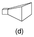
図2(a)から図2(e)は、図1に模式的に描写された非コイルアンテナ16、18に対する種々の可能性のある構成を示す。可能性のあるアンテナ形状のうちのもっとも基本的な形の1つは、ダイポールアンテナであり、これは図2(a)に示される。別の基本的な形は、図2(b)に示されたループアンテナである。さらに可能性のある形は、図2(c)に示すようなパッチアンテナであり、波を発生させる平面パネルを備える。
2 (a) to 2 (e) show various possible configurations for the
図2(a)から図2(c)に示されたアンテナは、マイクロ波およびミリ波領域において、当技術分野でよく知られる特徴的な角度分布を有する進行電磁波を発生させる。図2(c)に示されたパッチアンテナは、順方向に大部分のエネルギを放射するという点で、非対称である。しかしながら実施形態によっては、アンテナの指向性は、図2(d)および図2(e)に示されるようなホーン形状の導波路を付加することによって、高められる。 The antenna shown in FIGS. 2A to 2C generates traveling electromagnetic waves having a characteristic angular distribution well known in the art in the microwave and millimeter wave regions. The patch antenna shown in FIG. 2 (c) is asymmetric in that it radiates most of the energy in the forward direction. However, in some embodiments, the antenna directivity is enhanced by adding a horn-shaped waveguide as shown in FIGS. 2 (d) and 2 (e).
アンテナは、送受信される波の波長の少なくとも8分の1である最大寸法を有し、より典型的にはその波の半波長を超える最大寸法を有する有効部分を有する。しかしながら本発明に従って用いられる高周波数が与えられるとすると、これは、依然としてコネクタコンポーネントを極めて小型にすることを可能にする。 The antenna has a maximum dimension that is at least one-eighth of the wavelength of the transmitted and received wave, and more typically has an effective portion having a maximum dimension that exceeds the half wavelength of the wave. However, given the high frequencies used in accordance with the present invention, this still allows the connector component to be very small.
本発明に従って伝搬するマイクロ波を用いると、信頼性のある高データレート通信が、海水を通じてであっても達成できることを示すことができる。例えば最大1GBまでのレートであれば、最大10センチメートルまでの海水を通じた通信が可能であり、例えば最大1メートルまでのより長距離にわたって効果的な通信を実行することができる。これにより、物理的接触コネクタに比べて、やりがいのある海洋環境におけるマイクロ波の使用が大いに簡単化される。 With microwaves propagating according to the present invention, it can be shown that reliable high data rate communication can be achieved even through seawater. For example, if the rate is up to 1 GB, communication through seawater up to 10 centimeters is possible, and effective communication can be performed over longer distances, up to 1 meter, for example. This greatly simplifies the use of microwaves in challenging marine environments compared to physical contact connectors.
本発明のいくつかの実施形態のみならず高速データ通信において、コネクタの2つのコンポーネントは、電力を伝送することができる。これの背景にある原理が図3を参照して説明され、この特徴を有する実施形態が図4から図6に示される。図3を参照すると、一般に110によって指し示された磁気トランスは、少なくとも部分的に閉じた磁路130を画定するとともに少なくとも1つの1次巻線140を有する高透磁率の磁気コア120、およびコア120を介して互いに磁気的に相互結合された少なくとも1つの2次巻線150を含む。このようなトランス110はよく知られており、1次および2次巻線140、150間で潜在的に多量の電力を伝送することができる。さらに、磁気コア120を実装するために互いに接触することができる、複数の分離した構成部品160A、160Bに磁気コア120を実装することはさらに知られている。水中環境において交流電流(a.c.)を伝送するためにこのようなトランス110を用いることは、知られている。磁気コア120の内部に発生する磁気ヒステリシス損失が、トランス110に利用できる周波数領域の上限を画定するが、有益なことに、トランス110は、それを通じてかなりの電力が伝送されるとき、比較的高い交番周波数で動作する。巻線140、150を励磁するのに用いられる信号が、高周波数パルス幅変調(PWM:pulse-width-modulated)電子スイッチングユニット170から引き出されると、特にコア120が磁気漏れしやすいとき、かなりの高周波電気雑音がコア120の近辺に存在することがある。
In high speed data communications as well as some embodiments of the present invention, the two components of the connector can transmit power. The principle behind this is described with reference to FIG. 3, and embodiments having this feature are shown in FIGS. Referring to FIG. 3, a magnetic transformer, generally indicated by 110, includes a high permeability
トランス110が、無線リンク110とともに図4に図示された水中交流電力コネクタ装置100内に含まれるとき、潜在的問題が生じる。すなわち、パルス幅変調(PWM)トランス110によって発生した雑音が無線リンク110に結合して、信頼できるデータ通信が行えなくなるからである。このことは、先行技術において認識されていた。例えばこのようなクロストークに対処するために、上述した英国特許出願公開第2457796A号明細書は、水中のマルチモード無線通信システムにおいて光搬送波の利用を記載する。しかしながら過酷な水中環境において、光搬送波装置は、マリングロス(海洋生物)のために信頼できない可能性がある。
A potential problem arises when the
これに対し、本発明の実施形態は、図5に示された本発明の実施形態を参照して説明され、200によって一般に指し示されるように、既存の水中電力コネクタ装置と関連した欠点を回避する。上述した実施形態におけるように、水中コネクタ装置200は、第1コネクタコンポーネント210Aおよび第2コネクタコンポーネント210Bを含む。コンポーネント210A、210Bは、コネクタ装置200が対の状態にあると互いに接するように配置され、コネクタ装置200が対にならない状態にあると互いに空間的に分離される。コネクタ装置200は、実質的に環状、楕円形または多角形として実装された高磁気透磁率の磁気コア260を含むトランス250を含む。場合によっては、多角形は、丸いかどを設けて有害な磁束漏れを回避する。磁気コア260は、2つのコネクタコンポーネント210A、210B内にそれぞれ配置された2つの半コア270A、270Bとして実装される。コネクタコンポーネント210A、210Bのそれぞれにおいて、半コア270A、270Bのそれぞれは、同心的に配置され、コネクタ装置200が対の状態にあるとコンポーネント210A、210Bが接する表面にまたは表面の近くに配置された相補的極面280A、280Bを画定する。半コア270A、270B内に、それぞれ対応するコイル290A、290Bが配置され、コイル290A、290Bの1つ以上の巻線300は、それぞれ極面280A、280Bに対して同心的である。コア270A、270Bは、マイクロ波帯における損失の発生を最小化するように選ばれる。
In contrast, the embodiment of the present invention is described with reference to the embodiment of the present invention shown in FIG. 5 and, as generally indicated by 200, avoids the disadvantages associated with existing underwater power connector devices. To do. As in the embodiment described above, the
トランス250の中心領域300において、2つのコネクタコンポーネント210A、210B間に配置された、上述したのと同様な無線マイクロ波インターフェース310A、310Bが設けられる。無線インターフェース310A、310Bは、1つ以上の無線通信チャンネルを用いるために好適に実装される。1つ以上の無線マイクロ波通信チャンネルは、300MHzから300GHzまで延びている周波数スペクトラムの内部に好適に包含される。これによってもコネクタ装置200が、1Gビット/秒を超えるデータレートでそれを通じてデータ通信を提供することが可能となる。このような高データレートは、高精細度ステレオカメラ撮像システムをサポートするとき、および/または水中構造体の高速非破壊検査を実行するとき、例えばパイプライン、圧力容器、坑口装置などの水中設備内で例えば応力による微小亀裂の形成を渦電流測定によって検出するとき、非常に望ましい。場合によっては、無線インターフェース310A、310Bは光通信リンクが用いられ、例えば無線インターフェース310A、310Bは、図4に図示したようにコア260A、260Bの中心部に実装されるとともに、光通信リンクはコア260A、260Bの周囲に実装される。場合によっては、無線インターフェース310A、310Bは、これに加えてまたはこれに代えてコア260A、260Bの外周の周囲に実装される。
In the
無線インターフェース310A、310Bは、1GHzから6GHzの周波数範囲内で動作してもよい。このような無線動作領域において、1GB以上のデータ送信レートを達成することができる。 The wireless interfaces 310A, 310B may operate within a frequency range of 1 GHz to 6 GHz. In such a wireless operation region, a data transmission rate of 1 GB or more can be achieved.
マイクロ波/ミリ波搬送波を変調する信号に用いられる通信プロトコルは、WiFi(登録商標)、ブルートゥース(登録商標)、ZigBee(登録商標)などの既存のプロトコルから好適に選ばれる。これにより、メンテナンスまたは検査のためにコネクタコンポーネントのいずれかを船の上面に持ってくる必要がある場合、そのコネクタコンポーネントと船上の機器ととの間で容易に通信することが可能となる。 A communication protocol used for a signal that modulates a microwave / millimeter wave carrier is preferably selected from existing protocols such as WiFi (registered trademark), Bluetooth (registered trademark), and ZigBee (registered trademark). This allows easy communication between the connector component and the equipment on the ship when any of the connector components need to be brought to the upper surface of the ship for maintenance or inspection.
場合によっては、コンポーネント210A、210Bは、海洋生物の増殖を防止するために、コンポーネント210A、210Bの互いに接する表面に照射する周辺無線源600を含む。一部の電磁放射周波数は、その周波数が、生物活性に必須の生体分子の双極子モーメントに対応するとき、生体系に大きなダメージを与える。有益なことに、無線源600から提供された無線放射は、変調されて、コネクタ装置200を通じてデータ通信を相乗的に提供することもできる。場合によっては、無線源600は、無線インターフェース310A、310Bの一部である。場合によっては、無線インターフェース310A、310Bは、信号対雑音比を高めてデータ通信レートを潜在的に増大させるために、互いに直交する電界偏波方向の無線信号を用いることによって、異なる電界偏波方向の無線信号を利用するように動作可能である。
In some cases,
有益なことに無線インターフェース310A、310Bは、コネクタ装置200の中心軸の方に面し、インターフェース310A、310Bに隣接するコア270A、270Bの外面を用いて、コンポーネント210A、210B間の無線電磁放射を集束し凝縮するのを助けて、信号対雑音比を高め、その結果、コネクタ200が取り得る潜在的に最大の帯域幅を達成する。場合によってはこの外面は、無線放射伝搬が生じる、電磁石の内部容積350を実質的に取り囲む反射体として、空間的に延長される。上述したように、無線インターフェース310A、310Bは、以下に記すより多くのアンテナの種類:スタブアンテナ、導波路ホーンアンテナ、パッチアンテナ、ダイポールアンテナ、ループアンテナ、のうちの1つを好適に採用する。
Beneficially, the
図5および図6のコネクタ装置200の利点は、コンポーネント210A、210Bが互いに異なる角度を向いても対の状態にできるようにコネクタ装置200が回転対称形状に好適に実装されることにより、水中環境においてコネクタ200の操作をより柔軟にかつより容易にすることである。機械式結合機構360は、コア270A、270Bの外周の周囲に好適に設けられ、コネクタ装置200が対の状態にあるとき、コンポーネント210A、210Bが互いに堅牢に保持されることを確実にする。結合機構360は、バヨネット式のラッチ機構として好適に実装される。これに代えて、結合機構360は、電磁石を用いて実装され、例えば結合機構360が消勢されるとコネクタ装置200が本質的に分離する。
The advantages of the
コネクタ装置200は、内部の機能部品、例えばコネクタ装置200のコンポーネント210A、210Bの内部に設けられた、トランス250およびその巻線290A、290B、無線インターフェース310A、310Bならびに任意の電力および/または信号処理ユニット、を保護するように動作可能である材料内に好適にポッティング(樹脂盛り)され、さもなければ密封される。このようなポッティングは、例えばポリウレタンポリマー・プラスチック材料、シリコーンゴム、エポキシ樹脂、石英ガラスなどへのプラスチック材料ポッティングを含む。
The
例えば、海底石油およびガス掘削施設などの、粒子が充満し、光学的可視性が厳しく制限された状態にある水中環境において、コンポーネント210A、210Bが接合すると、無線インターフェース310A、310Bは、動作中に、場合によってはコンポーネント210A、210Bを中心を揃えるのを助けるために用いられる。コンポーネント210A、210Bが接合している間、コンポーネント210A、210Bを互いに対して横方向に移動させることは、無線インターフェース310A、310Bを通じてやり取りされる無線信号の強度を監視することによっておよび/またはトランス250を通じて電力伝送の効率を監視することによって好適に実行される。インターフェース310A、310Bを通した無線伝送の最大効率は、コンポーネント210A、210Bが接合するときに発生し、コンポーネント210A、210Bの同心軸が互いに一列に整列する。
In an underwater environment where the particles are full and the optical visibility is severely limited, such as subsea oil and gas drilling facilities, for example, when the
コンポーネント210A、210Bのうちの1つ以上は、水中ケーブルの端部に好適に設けられる。すなわちケーブルを通じて電力伝送および信号伝送を確立するためにケーブルを相互結合する方法を提供する。これに代えて、例えばコネクタのうちの1つ以上が、水中ケーブルが結合されやすい接続場所を装置上に設けるために、水中の装置上に設けられる。さらにこれに代えて、コンポーネント210A、210Bは、両方とも装置上に設けられる。例えばコンポーネント210A、210Bのうちの一方は遠隔海洋艇(ROV)500の多関節アーム510の遠位端上に設けられ、コンポーネント210A、210Bのうちの他方はROV500の交換可能な動力工具520上に設けられる。このような装置が、図7に模式的に示される。有益なことにROV500は、水中作業を行うとき、例えば測量、海難救出、検査、メンテナンス、修理および組み立て作業を実行するときなどROV500の動作中に、ROV500上で動的に交換しやすい、一式の交換可能な工具を含む。
One or more of the
水中コネクタ装置200は、海洋再生可能エネルギシステム、例えば海洋波エネルギ発電機、海洋風力タービン、海洋潮力エネルギ発生システム、に採用しやすい。さらに、水中コネクタ装置は、海洋石油、ガス探索および生産設備に用いられ、孤島、例えば列島内の小島へ、電気通信リンクおよび電力リンクを好適に提供し、浸水を被りやすい道路や浸水を被りやすい鉄道線路に沿って電気通信リンクおよび電力リンクを好適に提供する。コネクタ装置200のための種々の実用的な用途が、本発明を説明するこの特許文献の他の部分に提供される。
The
コネクタ装置200は、信号処理ユニット、データ処理ユニット、信号調整および電力処理電子デバイス、例えばPWMユニット、無線ユニットなど、を好適に含む。場合によっては、データ処理装置は、トランス250および無線インターフェース310A、310Bのうちの少なくとも1つの動的なインピーダンスマッチングを実行して、例えばトランス250を介したもっとも効率的な電力伝送および/またはインターフェース310A、310Bとの間における無線放射のもっとも効率的な伝送を確実にするように動作可能である。このような動的なインピーダンスマッチングは、もっとも有益な動作周波数の選択も好適に含む。例えば、コンポーネント210A、210Bの互いに接する表面上にある海洋生物によって、コア270A、270B間の分離が互いに少し広くなると、トランス250の巻線290A、290Bのインダクタンスが変化する。トランスが、もっとも効率的な電力伝送を確実にする高周波数共振態様で動作しているとき、巻線290A、290Bの調整は重要であり、コネクタ装置200内で、例えばトランス250に関して使用される動作周波数を動的に変更することによっておよび/または巻線290A、290Bとともに使用されるリアクタンスコンポーネントを動的に調整することによって(例えばキャパシタを調整することによって)、好適に動的に実装される。上述したように、リアクタンスコンポーネントを調整することによっておよび/または信号動作周波数、例えば信号搬送周波数を選択することによって無線インターフェース310A、310Bを調整することも、動作中にコネクタ装置200内で好適に実行される。
The
図8を参照すると、水中環境710、例えば海底において、700によって一般に指し示された水中構成が示される。遠隔操作艇(ROV)720は、アンビリカルケーブルを介して表面位置または他の浸漬型装置(図示せず)へ結合される。ROV720は、ROV接続箱(JB:junction box)730を含み、遠位端グリップ用あご状部750およびビューイングカメラ装置760を含む多関節アーム740も備える。可撓性ケーブル770は、上述したようにROV JB730とコネクタ210Aとの間で結合される。構成700は、上述したようにケーブル800を介してコンポーネント210Bへ結合された、水中工具および/または海中制御モジュール810を含む水中設備をさらに含む。場合によっては、コンポーネント210Aは、グリップ用あご状部750によってより把持されやすくするROVハンドル820を含む。ケーブル770は、例えばSeaCon(登録商標)55シリーズ製品のコネクタで終端される。ROV720は、動作中に好適に遠隔制御されて、接続を形成および遮断するために、それぞれ、コンポーネント210A、210Bを対の状態および対にならない状態にする。この構成およびその関連した動作によって、例えば海底装着装置にまたは一時的に水中に展開した装置に電力および通信を提供することが可能となる。
Referring to FIG. 8, an underwater configuration generally indicated by 700 in an
それゆえに本発明の実施形態は、潜在的により接続しやすくかつより切断しやすくし、より効率的にかつ高められた信号帯域幅で無線信号を結合でき、容易に入手可能な構成部品を用いてより製造しやすい、改善された水中コネクタ装置を提供できることが理解される。 Therefore, embodiments of the present invention are potentially more connectable and easier to disconnect, can couple wireless signals more efficiently and with increased signal bandwidth, and use readily available components It will be appreciated that an improved underwater connector device can be provided that is easier to manufacture.
上述した本発明の実施形態への修正形態は、添付の請求項によって画定されるような本発明の範囲から逸脱しなければ、可能である。本発明を説明し請求するのに用いられる、「含む」、「備える」、「組み込む」、「から成る」、「有する」、「である」などの表現は、非排他的なやり方で解釈されるように意図されており、すなわち明示的には説明されていないアイテム、コンポーネントまたは要素も存在していることを可能にする。単数への参照は、複数にも関係すると解釈されるべきである。添付の請求項内の括弧の内側に含まれた数字は、請求項の理解を助けるように意図されており、これらの請求項によって請求された主題を限定するようには、解釈されるべきではない。 Modifications to the embodiments of the invention described above are possible without departing from the scope of the invention as defined by the appended claims. The expressions “including”, “comprising”, “including”, “consisting of”, “having”, “being”, etc. used to describe and claim the present invention are interpreted in a non-exclusive manner. It also allows for the presence of items, components or elements that are intended to be, i.e. not explicitly described. References to the singular should be construed as involving the plural. The numbers within parentheses in the appended claims are intended to aid the understanding of the claims and should not be construed as limiting the claimed subject matter by these claims. Absent.
Claims (20)
前記第1コンポーネントは、第1非コイルアンテナを備え、
前記第1非コイルアンテナは、300MHzと300GHzとの間の周波数を有する電磁搬送波を用いて、前記第2コンポーネントへデータを送信するように構成され、前記第1非コイルアンテナは、前記搬送波の波長の8分の1以上の最大外形寸法を有する第1潜水可能カプセル化体内に収容され、
前記第2コンポーネントは、前記電磁搬送波を用いて、前記第1コンポーネントの前記第1非コイルアンテナからデータを受信するように構成された第2非コイルアンテナを備え、前記第2非コイルアンテナは、前記搬送波の波長の8分の1以上である最大外形寸法を有する第2潜水可能カプセル化体内に収容される、水中コネクタ装置。 An underwater connector device, comprising a first component and a second component, for transmitting data from the first component to the second component,
The first component comprises a first non-coil antenna ;
The first non-coil antenna is configured to transmit data to the second component using an electromagnetic carrier having a frequency between 300 MHz and 300 GHz, and the first non-coil antenna is configured to transmit a wavelength of the carrier. In a first submersible encapsulant having a maximum outer dimension of 1/8 or more of
The second component comprises a second non-coil antenna configured to receive data from the first non-coil antenna of the first component using the electromagnetic carrier, wherein the second non-coil antenna is An underwater connector device housed in a second submersible encapsulant having a maximum outer dimension that is one-eighth or more of the wavelength of the carrier wave.
前記第1水中コンポーネント内の第1非コイルアンテナから前記第2水中コンポーネント内の対応する受信部へ300MHzと300GHzとの間の周波数を有する電磁搬送波を送信するステップを備え、
前記第1非コイルアンテナは、前記搬送波の波長の8分の1以上である最大外形寸法を有する第1潜水可能カプセル化体内に収容され、
前記受信部は、前記電磁搬送波を用いて、前記第1水中コンポーネントの前記第1非コイルアンテナからデータを受信する第2非コイルアンテナを備え、前記第2非コイルアンテナは、前記搬送波の波長の8分の1以上である最大外形寸法を有する第2潜水可能カプセル化体内に収容される、方法。 A method of transmitting data between a first underwater component and a second underwater component,
Comprising the step of transmitting an electromagnetic carrier wave having a frequency between the corresponding 300MHz and 300GHz to the receiving unit in the second water component from the first non-coiled antenna in the first water component,
The first non-coil antenna is housed in a first submersible encapsulant having a maximum outer dimension that is one-eighth or more of the wavelength of the carrier;
The receiving unit includes a second non-coil antenna that receives data from the first non-coil antenna of the first underwater component using the electromagnetic carrier wave, and the second non-coil antenna has a wavelength of the carrier wave. A method of being contained within a second submersible encapsulation having a maximum outer dimension that is one-eighth or greater.
Applications Claiming Priority (3)
| Application Number | Priority Date | Filing Date | Title |
|---|---|---|---|
| NO20110292 | 2011-02-21 | ||
| NO20110292 | 2011-02-21 | ||
| PCT/EP2012/052873 WO2012113757A1 (en) | 2011-02-21 | 2012-02-20 | Underwater connector arrangement |
Publications (3)
| Publication Number | Publication Date |
|---|---|
| JP2014514894A JP2014514894A (en) | 2014-06-19 |
| JP2014514894A5 JP2014514894A5 (en) | 2015-04-02 |
| JP6074368B2 true JP6074368B2 (en) | 2017-02-01 |
Family
ID=45808787
Family Applications (1)
| Application Number | Title | Priority Date | Filing Date |
|---|---|---|---|
| JP2013553966A Active JP6074368B2 (en) | 2011-02-21 | 2012-02-20 | Underwater connector device |
Country Status (9)
| Country | Link |
|---|---|
| US (2) | US9490521B2 (en) |
| EP (1) | EP2678958B1 (en) |
| JP (1) | JP6074368B2 (en) |
| AU (1) | AU2012219689B2 (en) |
| BR (1) | BR112013021317B1 (en) |
| CA (1) | CA2827456C (en) |
| DK (1) | DK2678958T3 (en) |
| GB (1) | GB2504018B (en) |
| WO (1) | WO2012113757A1 (en) |
Families Citing this family (38)
| Publication number | Priority date | Publication date | Assignee | Title |
|---|---|---|---|---|
| JP5034857B2 (en) * | 2007-10-12 | 2012-09-26 | ソニー株式会社 | Connector system |
| EP3595124A1 (en) | 2010-12-10 | 2020-01-15 | Hayward Industries, Inc. | Power supplies for pool and spa equipment |
| GB2504018B (en) * | 2011-02-21 | 2014-12-31 | Wisub As | Underwater Connector Arrangement |
| EP2790294B1 (en) * | 2011-12-07 | 2016-05-11 | IHI Corporation | Power transmission system |
| WO2014034491A1 (en) * | 2012-08-31 | 2014-03-06 | 日本電気株式会社 | Electric power transmission device and electric power transmission method |
| KR102186672B1 (en) | 2012-10-17 | 2020-12-08 | 트랜스오션 이노베이션 랩스 리미티드 | Subsea processor for underwater drilling operations |
| EP2919365B1 (en) * | 2012-11-08 | 2018-08-01 | Nec Corporation | Electric power transmission device and electric power transmission method |
| US9281906B2 (en) * | 2012-12-31 | 2016-03-08 | Hydril USA Distribution LLC | Subsea power and data communication apparatus and related methods |
| BR112015019096A2 (en) | 2013-03-01 | 2017-07-18 | Halliburton Energy Services Inc | profiling cable connector including an electromagnet and a metal |
| JP6098284B2 (en) * | 2013-03-28 | 2017-03-22 | 日本電気株式会社 | Power transmission system, power transmission device, power reception device, and power transmission method |
| EP2802092A1 (en) * | 2013-05-06 | 2014-11-12 | ATLAS Elektronik GmbH | System and method for seafloor exploration |
| FR3012684B1 (en) * | 2013-10-29 | 2015-11-13 | Inst Francais De Rech Pour L’Expl De La Mer – Ifremer | UNDERWATER RADIO FREQUENCY ANTENNA |
| US20150116496A1 (en) * | 2013-10-29 | 2015-04-30 | Ottarr, Llc | Camera, Sensor and/or Light-Equipped Anchor |
| GB2527782B (en) | 2014-07-01 | 2017-01-18 | Flintstone Tech Ltd | A connector having an inductive transmission |
| WO2016191555A1 (en) | 2015-05-26 | 2016-12-01 | The Board Of Trustees Of The University Of Illinois | Method and apparatus for ultra high bandwidth acoustic communication and power transfer |
| US9906067B1 (en) | 2015-06-30 | 2018-02-27 | Garrity Power Services Llc | Apparatus, system and method to wirelessly charge/discharge a battery |
| JP6836236B2 (en) * | 2015-08-28 | 2021-02-24 | 長崎県 | Non-contact power transmission device |
| US10128909B2 (en) * | 2015-12-11 | 2018-11-13 | Oceaneering International, Inc. | Subsea contactless connector system and method with extremely high data transfer rate |
| EP3510615B1 (en) * | 2016-09-07 | 2021-10-20 | FMC Technologies, Inc. | Wireless electrical feedthrough wetmate connector |
| GB2554465A (en) * | 2016-09-30 | 2018-04-04 | Statoil Petroleum As | Umbilical installation method and system |
| JP6848320B2 (en) * | 2016-10-06 | 2021-03-24 | 富士ゼロックス株式会社 | Underwater mobile |
| DE102017101891A1 (en) * | 2016-10-10 | 2018-04-12 | Weidmüller Interface GmbH & Co. KG | Apparatus for contactless inductive energy transmission and method of operation for such a device |
| FR3079081B1 (en) * | 2018-03-19 | 2022-12-09 | Naval Energies | CONNECTOR FOR CONNECTING SUBMARINE CABLES AND IN PARTICULAR UMBILICAL CABLES FOR MARINE RENEWABLE ENERGY FARMS |
| WO2019246336A1 (en) * | 2018-06-20 | 2019-12-26 | Hayward Industries, Inc. | Power supplies for pool and spa equipment |
| KR102590602B1 (en) * | 2018-10-30 | 2023-10-16 | 한화오션 주식회사 | Separable buoy type antenna and the underwater moving body having the same |
| US11160144B2 (en) * | 2018-11-21 | 2021-10-26 | Illinois Tool Works Inc. | Modular transformers and induction heating systems having modular transformers |
| CN109861401A (en) * | 2018-12-20 | 2019-06-07 | 中国船舶重工集团公司七五0试验场 | A kind of efficient wireless coupling power supply structure of underwater equipment |
| EP3806352A1 (en) * | 2019-10-10 | 2021-04-14 | Scubajet GmbH | Connection interface for use under water |
| CN110808786A (en) * | 2019-11-20 | 2020-02-18 | 中国船舶重工集团公司第七0五研究所 | High-power underwater wireless optical communication transmitter |
| BR112022016751A2 (en) | 2020-02-24 | 2022-11-08 | Schlumberger Technology Bv | SAFETY VALVE WITH ELECTRIC ACTUATORS |
| US11075486B1 (en) | 2020-03-02 | 2021-07-27 | Northrop Grumman Systems Corporation | Signal connector system |
| JP7391745B2 (en) * | 2020-03-26 | 2023-12-05 | 矢崎エナジーシステム株式会社 | connector device |
| BE1028203B1 (en) * | 2020-04-09 | 2021-11-08 | Phoenix Contact Gmbh & Co | Coupling device for wireless data and energy transmission and a coupling system for wireless data and energy transmission |
| US11038594B1 (en) | 2020-05-13 | 2021-06-15 | Northrop Grumman Systems Corporation | Self-insulating high bandwidth connector |
| US11955684B2 (en) | 2020-06-25 | 2024-04-09 | Intel Corporation | Components for millimeter-wave communication |
| US20210408657A1 (en) * | 2020-06-25 | 2021-12-30 | Intel Corporation | Components for millimeter-wave communication |
| US11569608B2 (en) | 2021-03-30 | 2023-01-31 | Northrop Grumman Systems Corporation | Electrical connector system |
| NO20220927A1 (en) * | 2022-08-29 | 2024-03-01 | Blue Logic As | Apparatus for wireless transmission of power and data in high-pressure environments |
Family Cites Families (52)
| Publication number | Priority date | Publication date | Assignee | Title |
|---|---|---|---|---|
| US3299398A (en) * | 1965-01-14 | 1967-01-17 | John B Hersey | Deep water radio-acoustic buoy |
| US3469627A (en) * | 1967-06-29 | 1969-09-30 | Mobil Oil Corp | Subsea production system |
| GB1501502A (en) | 1975-01-08 | 1978-02-15 | Pelcon Ltd | Inductive connectors |
| GB2077514A (en) | 1981-06-04 | 1981-12-16 | Decca Ltd | Microwave frequency rotating joint |
| JPH01156640U (en) | 1988-04-19 | 1989-10-27 | ||
| US4915118A (en) | 1988-04-20 | 1990-04-10 | P. H. Glatfelter Company | Smoking article wrapper and method of making same |
| EP0436766A1 (en) | 1990-01-12 | 1991-07-17 | Siemens Aktiengesellschaft | Medical diagnostic system |
| US5619528A (en) | 1993-04-16 | 1997-04-08 | Trans Video Electronics | High speed teleconference system |
| JPH0729502A (en) | 1993-07-14 | 1995-01-31 | Sony Corp | Internal beam shielding plate for cathode-ray tube and color selecting mechanism assembly body |
| JP2600516Y2 (en) * | 1993-11-02 | 1999-10-12 | 川崎重工業株式会社 | Electric / optical composite connector |
| GB2289989B (en) | 1994-05-25 | 1999-01-06 | Nokia Mobile Phones Ltd | Adaptive antenna matching |
| GB2297667A (en) | 1995-02-01 | 1996-08-07 | Brian Page Controls Ltd | Portable control device with multi-mode transmission |
| US5592156A (en) * | 1995-10-05 | 1997-01-07 | James; Robert | Underwater alpha-numeric communication system |
| US5977841A (en) | 1996-12-20 | 1999-11-02 | Raytheon Company | Noncontact RF connector |
| US6154179A (en) * | 1997-11-28 | 2000-11-28 | Kohno; Kazuo | Underground or underwater antennas |
| US6164179A (en) * | 1998-10-05 | 2000-12-26 | The United States Of America As Represented By The Secretary Of The Navy | Submarine deployable vertical launch spar buoy |
| JP3437119B2 (en) | 1999-06-07 | 2003-08-18 | 株式会社オートネットワーク技術研究所 | Electromagnetic induction type connector |
| US6763195B1 (en) | 2000-01-13 | 2004-07-13 | Lightpointe Communications, Inc. | Hybrid wireless optical and radio frequency communication link |
| GB0013910D0 (en) * | 2000-06-08 | 2000-11-29 | Secr Defence | Underwater communications system |
| US6525762B1 (en) * | 2000-07-05 | 2003-02-25 | The United States Of America As Represented By The Secretary Of The Navy | Wireless underwater video system |
| TW481393U (en) | 2000-12-05 | 2002-03-21 | Elan Microelectronics Corp | Device capable of adjusting the ultrasonic and infrared carrier frequencies |
| US20020122230A1 (en) | 2001-03-05 | 2002-09-05 | Hossein Izadpanah | Hybrid RF and optical wireless communication link and network structure incorporating it therein |
| US6807127B2 (en) * | 2001-11-19 | 2004-10-19 | John F. McGeever, Jr. | Navigational device for an underwater diver |
| US7301474B2 (en) | 2001-11-28 | 2007-11-27 | Schlumberger Technology Corporation | Wireless communication system and method |
| US6701252B2 (en) * | 2002-01-15 | 2004-03-02 | Richard Ivan Brown | System for underwater GPS navigation |
| US6738314B1 (en) * | 2003-01-31 | 2004-05-18 | L3 Communications Corporation | Autonomous mine neutralization system |
| GB0428046D0 (en) | 2004-12-22 | 2005-01-26 | Artimi Ltd | Contactless connector systems |
| EP1839052B1 (en) | 2005-01-18 | 2015-02-25 | Benthic Geotech Pty Ltd | Instrumentation probe for in situ measurement and testing of seabed |
| EP2362559A1 (en) | 2005-06-13 | 2011-08-31 | WFS Technologies Limited | Underwater communications system |
| US8305227B2 (en) | 2005-06-15 | 2012-11-06 | Wfs Technologies Ltd. | Wireless auxiliary monitoring and control system for an underwater installation |
| US7711322B2 (en) | 2005-06-15 | 2010-05-04 | Wireless Fibre Systems | Underwater communications system and method |
| US20080199124A1 (en) | 2005-08-29 | 2008-08-21 | Tadao Nagatsuma | OPTICAL DEVICE FOR GENERATING AND MODULATING THz AND OTHER HIGH FREQUENCY SIGNALS |
| US20090102590A1 (en) | 2006-02-28 | 2009-04-23 | Wireless Fibre Systems | Underwater Electrically Insulated Connection |
| DE102006022713B4 (en) | 2006-05-12 | 2018-11-08 | Knick Elektronische Messgeräte GmbH & Co. KG | Connector for transmitting signals, in particular for contactless inductive transmission of measuring signals |
| US20140098642A1 (en) * | 2006-08-03 | 2014-04-10 | Wfs Technologies Ltd. | Underwater Communications |
| GB2445015B (en) | 2006-12-19 | 2011-03-23 | Wireless Fibre Systems Ltd | Electromagnetic below ice communications |
| JP4924122B2 (en) | 2007-03-16 | 2012-04-25 | 富士ゼロックス株式会社 | Non-contact transmission device |
| WO2008117635A1 (en) * | 2007-03-28 | 2008-10-02 | Radio Communication Systems Ltd. | Magnetic force wave communication apparatus |
| GB0725265D0 (en) | 2007-12-28 | 2008-02-06 | Rhodes Mark | Inductive communication system |
| GB0802807D0 (en) | 2008-02-15 | 2008-03-26 | Rhodes Mark | Through water multimode communications system |
| US8179279B2 (en) | 2008-02-26 | 2012-05-15 | Vetco Gray Inc. | Method and device for producing hydrocarbons using wireless communication |
| GB2458944B (en) | 2008-04-04 | 2012-06-27 | Vetco Gray Controls Ltd | Communication system for a hydrocarbon extraction plant |
| EP2294728A1 (en) * | 2008-05-01 | 2011-03-16 | Battelle Memorial Institute | Spectrally efficient digital data transmission utilizing phase encoded mmw |
| GB2464945B (en) | 2008-10-29 | 2013-07-10 | Wfs Technologies Ltd | Electrical connector system |
| GB0823436D0 (en) | 2008-12-23 | 2009-01-28 | Rhodes Mark | Inductively coupled memory transfer system |
| GB0900946D0 (en) | 2009-01-21 | 2009-03-04 | Rhodes Mark | Underwater wireless network access point |
| US20120007442A1 (en) | 2009-02-06 | 2012-01-12 | Mark Rhodes | Rotary data and power transfer system |
| US20110311231A1 (en) * | 2009-02-26 | 2011-12-22 | Battelle Memorial Institute | Submersible vessel data communications system |
| NO346401B1 (en) | 2009-04-01 | 2022-07-11 | Fmc Tech Inc | Wireless underwater monitoring and control system |
| US8946941B2 (en) | 2010-09-14 | 2015-02-03 | Monterey Bay Aquarium Research Institute | Wireless power and data transfer device for harsh and extreme environments |
| GB2504018B (en) * | 2011-02-21 | 2014-12-31 | Wisub As | Underwater Connector Arrangement |
| US9705186B1 (en) * | 2015-04-13 | 2017-07-11 | The United States Of America As Represented By The Secretary Of The Navy | Scalable vertical buoyant cable antenna |
-
2012
- 2012-02-20 GB GB1316778.8A patent/GB2504018B/en active Active
- 2012-02-20 BR BR112013021317-5A patent/BR112013021317B1/en active IP Right Grant
- 2012-02-20 DK DK12707058.9T patent/DK2678958T3/en active
- 2012-02-20 WO PCT/EP2012/052873 patent/WO2012113757A1/en active Application Filing
- 2012-02-20 CA CA2827456A patent/CA2827456C/en active Active
- 2012-02-20 US US14/000,324 patent/US9490521B2/en active Active
- 2012-02-20 AU AU2012219689A patent/AU2012219689B2/en active Active
- 2012-02-20 JP JP2013553966A patent/JP6074368B2/en active Active
- 2012-02-20 EP EP12707058.9A patent/EP2678958B1/en active Active
-
2016
- 2016-10-04 US US15/285,327 patent/US10355334B2/en active Active
Also Published As
| Publication number | Publication date |
|---|---|
| GB2504018A (en) | 2014-01-15 |
| AU2012219689A1 (en) | 2013-10-10 |
| US20130321223A1 (en) | 2013-12-05 |
| DK2678958T3 (en) | 2020-05-18 |
| CA2827456C (en) | 2020-12-01 |
| JP2014514894A (en) | 2014-06-19 |
| GB2504018B (en) | 2014-12-31 |
| GB201316778D0 (en) | 2013-11-06 |
| EP2678958A1 (en) | 2014-01-01 |
| US9490521B2 (en) | 2016-11-08 |
| US10355334B2 (en) | 2019-07-16 |
| BR112013021317A2 (en) | 2016-10-25 |
| EP2678958B1 (en) | 2020-04-15 |
| WO2012113757A1 (en) | 2012-08-30 |
| BR112013021317B1 (en) | 2022-06-21 |
| CA2827456A1 (en) | 2012-08-30 |
| US20170054195A1 (en) | 2017-02-23 |
| AU2012219689B2 (en) | 2016-04-14 |
Similar Documents
| Publication | Publication Date | Title |
|---|---|---|
| JP6074368B2 (en) | Underwater connector device | |
| US7826794B2 (en) | Distributed underwater electromagnetic communication system | |
| US8577288B2 (en) | Subsea transfer system providing wireless data transfer, electrical power transfer and navigation | |
| US20090102590A1 (en) | Underwater Electrically Insulated Connection | |
| US20120007442A1 (en) | Rotary data and power transfer system | |
| US20110076940A1 (en) | Underwater wireless communications hotspot | |
| CN102267542A (en) | Non-contact electric energy supply and data transmission device for underwater sensor of buoy system | |
| GB2457581A (en) | An array of subsea radio modems is distributed on the seabed to provide a radio communications network | |
| WO2015087724A1 (en) | Magnetic loop antenna and magnetic-field communication device using same | |
| US20100039285A1 (en) | Wireless drill string telemetry | |
| WO2013068739A2 (en) | Improved monitoring of subsea installations | |
| US20100322293A1 (en) | Communication between submerged station and airborne vehicle | |
| WO2013114138A2 (en) | Improved subsea installation deployment | |
| US20100227552A1 (en) | Underwater radio antenna | |
| US7113668B2 (en) | System for the transmission of signals to or between underwater installations | |
| US20100227551A1 (en) | Buoy supported underwater radio antenna | |
| CA2929061A1 (en) | Wellbore e-field wireless communication system | |
| GB2483374A (en) | Transferring power between a fixed unit and a rotating unit using a rotary transformer, and also transferring data | |
| CN110311267A (en) | A kind of wet plug-in connector of contactless delivery of energy communication mixing in seabed | |
| GB2479195A (en) | Buoy supported underwater radio antenna | |
| Yugang et al. | Research on information interaction design of underwater multi-platform of deep-sea vehicle based on acoustic optic and electromagnetic transmission technology | |
| WO2014068313A9 (en) | Improved subsea installation deployment | |
| JP2014225866A (en) | Connector between two apparatuses for food production | |
| WO2013088157A1 (en) | Mooring monitoring system and method for offshore apparatus | |
| Wrathall et al. | Magneto-inductive communications |
Legal Events
| Date | Code | Title | Description |
|---|---|---|---|
| A521 | Request for written amendment filed |
Free format text: JAPANESE INTERMEDIATE CODE: A523 Effective date: 20150210 |
|
| A621 | Written request for application examination |
Free format text: JAPANESE INTERMEDIATE CODE: A621 Effective date: 20150210 |
|
| A977 | Report on retrieval |
Free format text: JAPANESE INTERMEDIATE CODE: A971007 Effective date: 20151022 |
|
| A131 | Notification of reasons for refusal |
Free format text: JAPANESE INTERMEDIATE CODE: A131 Effective date: 20151027 |
|
| A521 | Request for written amendment filed |
Free format text: JAPANESE INTERMEDIATE CODE: A523 Effective date: 20160125 |
|
| A131 | Notification of reasons for refusal |
Free format text: JAPANESE INTERMEDIATE CODE: A131 Effective date: 20160621 |
|
| TRDD | Decision of grant or rejection written | ||
| A01 | Written decision to grant a patent or to grant a registration (utility model) |
Free format text: JAPANESE INTERMEDIATE CODE: A01 Effective date: 20161220 |
|
| A61 | First payment of annual fees (during grant procedure) |
Free format text: JAPANESE INTERMEDIATE CODE: A61 Effective date: 20170106 |
|
| R150 | Certificate of patent or registration of utility model |
Ref document number: 6074368 Country of ref document: JP Free format text: JAPANESE INTERMEDIATE CODE: R150 |
|
| R250 | Receipt of annual fees |
Free format text: JAPANESE INTERMEDIATE CODE: R250 |
|
| R250 | Receipt of annual fees |
Free format text: JAPANESE INTERMEDIATE CODE: R250 |
|
| R250 | Receipt of annual fees |
Free format text: JAPANESE INTERMEDIATE CODE: R250 |
|
| R250 | Receipt of annual fees |
Free format text: JAPANESE INTERMEDIATE CODE: R250 |
|
| R250 | Receipt of annual fees |
Free format text: JAPANESE INTERMEDIATE CODE: R250 |