JP6073718B2 - Optical lens - Google Patents
Optical lens Download PDFInfo
- Publication number
- JP6073718B2 JP6073718B2 JP2013056657A JP2013056657A JP6073718B2 JP 6073718 B2 JP6073718 B2 JP 6073718B2 JP 2013056657 A JP2013056657 A JP 2013056657A JP 2013056657 A JP2013056657 A JP 2013056657A JP 6073718 B2 JP6073718 B2 JP 6073718B2
- Authority
- JP
- Japan
- Prior art keywords
- light
- guide plate
- lens
- light guide
- light incident
- Prior art date
- Legal status (The legal status is an assumption and is not a legal conclusion. Google has not performed a legal analysis and makes no representation as to the accuracy of the status listed.)
- Active
Links
- 230000003287 optical effect Effects 0.000 title claims description 40
- 238000009792 diffusion process Methods 0.000 claims description 3
- 238000000034 method Methods 0.000 description 5
- 238000004519 manufacturing process Methods 0.000 description 4
- 239000000463 material Substances 0.000 description 3
- 238000004088 simulation Methods 0.000 description 3
- 230000007423 decrease Effects 0.000 description 2
- 238000010586 diagram Methods 0.000 description 1
- 230000000694 effects Effects 0.000 description 1
- 239000012780 transparent material Substances 0.000 description 1
Images


Description
本発明は、光学レンズに関するものであり、詳しくは、光源と導光板との間に配設して、光源からの出射光の光路制御を行って導光板に入射させる機能を持たせた光学レンズに関する。 The present invention relates to an optical lens, and more specifically, an optical lens that is disposed between a light source and a light guide plate and has a function of controlling the optical path of light emitted from the light source and causing the light to enter the light guide plate. About.
従来、面発光の導光板に光を入射する場合、導光板に垂直な方向から入射する方法と導光板に平行な方向から入射する方法とがある。 Conventionally, when light is incident on a surface emitting light guide plate, there are a method of entering light from a direction perpendicular to the light guide plate and a method of entering light from a direction parallel to the light guide plate.
そのうち、導光板に垂直な方向から光を入射する方法は、導光板の厚み方向に対するスペースが必要となり、光源及び導光板を含む光学ユニットの大型化を招くことになる。 Among them, the method of entering light from the direction perpendicular to the light guide plate requires a space in the thickness direction of the light guide plate, which leads to an increase in the size of the optical unit including the light source and the light guide plate.
一方、導光板に平行な方向から光を入射する方法は、導光板の厚み方向に対するスペースを必要とせず、光学ユニットの薄型化を図ることができる。 On the other hand, the method of entering light from a direction parallel to the light guide plate does not require a space in the thickness direction of the light guide plate, and can reduce the thickness of the optical unit.
導光板に平行な方向から光を入射する方法の従来例としては、例えば、特許文献1に図1として示された構成のものが開示されている。それは、導光板の平坦な端面近傍に光源のLEDを複数個配置し、LEDからの出射光を端面を介して導光板内に入射させるものである。この場合、LEDから導光板の厚み方向に垂直な方向(面方向)に出射された光は、LEDの光軸に対する角度が大きくなるにつれて端面で反射される割合が高くなり、導光板内への光の取り込み効率が低下する。 As a conventional example of a method of entering light from a direction parallel to the light guide plate, for example, a configuration shown in FIG. That is, a plurality of light source LEDs are arranged in the vicinity of a flat end face of a light guide plate, and light emitted from the LEDs enters the light guide plate through the end face. In this case, the light emitted from the LED in the direction (plane direction) perpendicular to the thickness direction of the light guide plate is reflected at the end face as the angle with respect to the optical axis of the LED increases, and the light enters the light guide plate. Light capture efficiency decreases.
そこで、導光板内への光の取り込み効率を高めるために、導光板の光入射面を凹円弧状とする方法、及び、凹円弧状の光入射面をシボ状の粗面にする方法が開示されている(特許文献2参照。)。 Accordingly, a method of making the light incident surface of the light guide plate into a concave arc shape and a method of making the concave arc-shaped light incident surface into a rough rough surface in order to increase the efficiency of capturing light into the light guide plate are disclosed. (See Patent Document 2).
ところで、上記特許文献2に記載された導光板の光入射面を凹円弧状とする方法は、導光板の面方向に対する光取り込み効率は改善されるが、導光板の厚み方向に対する光取り込み効率が低下する。また、凹円弧状の光入射面をシボ状の粗面にする方法は、光源からの出射光が光源近傍の光入射面で拡散されるため、導光板の、光源から離れた位置に到達する光の光量が低下する。 By the way, although the method of making the light incident surface of the light guide plate described in Patent Document 2 a concave arc shape improves the light capturing efficiency in the surface direction of the light guide plate, the light capturing efficiency in the thickness direction of the light guide plate is improved. descend. In addition, the method of making the concave arc-shaped light incident surface into a rough rough surface reaches the position of the light guide plate away from the light source because the light emitted from the light source is diffused on the light incident surface near the light source. The amount of light decreases.
そこで、本発明は上記問題に鑑みて創案なされたもので、その目的とするところは、光源と導光板との間に配設して、光源からの出射光を導光板内に最大限に取り込んで光の利用効率を高めることができる、光学レンズを提供することにある。 Therefore, the present invention was devised in view of the above problems, and the object of the present invention is to arrange between the light source and the light guide plate so that the light emitted from the light source is taken into the light guide plate to the maximum extent. An object of the present invention is to provide an optical lens that can increase the light use efficiency.
上記課題を解決するために、本発明の請求項1に記載された発明は、光源と、端面から入射した光を導光して表面の光出射面から面状に出射する導光板との間に配設して、前記光源からの出射光の光路制御を行って前記導光板の端面から該導光板内に入射させる光学レンズであって、前記光学レンズは細長形状を有し、且つ裏面側と表面側の互いに対向する位置の夫々に光入射部と光出射部が設けられると共に前記光入射部と前記光出射部が長手方向に所定の間隔で複数箇所に設けられており、前記光入射部は、前記レンズの厚み方向に延びる軸を主軸とする凸状の双曲線を前記レンズの長手方向に沿って円弧状に延長した凹円弧状双曲面からなる第1光入射面と、前記第1光入射面の前記レンズの短手方向の両側に位置し、前記双曲線の両端の夫々から下方外側に延びる直線を前記レンズの長手方向に沿って円弧状に延長した扇状平面からなる一対の第2光入射面を備え、前記光出射部は、前記レンズの短手方向に延長された凸円柱面からなる第1光出射面を備えていることを特徴とするものである。
In order to solve the above-mentioned problem, the invention described in
また、本発明の請求項2に記載された発明は、請求項1において、隣接する前記光入射部同士の間には、前記レンズの短手方向に延びる三角柱が長手方向に連続して平行に並設された光反射部が形成され、隣接する前記光出射部同士の間には、平坦面からなる第2光出射面が形成されていることを特徴とするものである。 Further, according to a second aspect of the present invention, in the first aspect, between the adjacent light incident portions, a triangular prism extending in the lateral direction of the lens is continuously parallel to the longitudinal direction. The light reflecting portions arranged in parallel are formed, and a second light emitting surface made of a flat surface is formed between the adjacent light emitting portions.
また、本発明の請求項3に記載された発明は、請求項1又は請求項2において、前記導光板の端面の形状は、前記レンズの表面の形状に沿った形状を有していることを特徴とするものである。
The invention described in claim 3 of the present invention is that, in
また、本発明の請求項4に記載された発明は、請求項1〜請求項3のいずれかにおいて、前記導光板は、裏面に光拡散処理が施されていることを特徴とするものである。
The invention described in claim 4 of the present invention is characterized in that in any one of
また、本発明の請求項5に記載された発明は、請求項1〜請求項4のいずれかにおいて、前記レンズと前記導光板は、屈折率が同一あるいはほぼ同じ屈折率であることを特徴とするものである。
The invention described in claim 5 of the present invention is characterized in that, in any one of
また、本発明の請求項6に記載された発明は、請求項1〜請求項5いずれかにおいて、前記第1光入射面の焦点位置に光源としてLEDを配設することを特徴とするものである。 According to a sixth aspect of the present invention, in any one of the first to fifth aspects, an LED is disposed as a light source at a focal position of the first light incident surface. is there.
本発明の光学レンズは、光入射部に、レンズの厚み方向に延びる軸を主軸とする凸状の双曲線を前記レンズの長手方向に沿って円弧状に延長した凹円弧状双曲面からなる第1光入射面を設けた。それにより、光源から出射して第1光入射面を介してレンズ内に入射した光は、レンズの長手方向に対しては放射状に広がり短手方向に対しては集光するように光路制御されて第1光出射面を介して導光板内に取り込まれる。 In the optical lens of the present invention, a light incident portion is formed of a concave arc-shaped hyperboloid obtained by extending a convex hyperbola having a main axis extending in the lens thickness direction as an arc along the longitudinal direction of the lens. A light incident surface was provided. As a result, the optical path of the light emitted from the light source and entering the lens through the first light incident surface spreads radially in the longitudinal direction of the lens and is condensed in the lateral direction. And is taken into the light guide plate through the first light exit surface.
その結果、導光板は光出射面において、レンズの長手方向の光路制御によって光出射面の広範囲に亘って発光領域が形成され、レンズの短手方向の光路制御によって光出射面の発光領域の高輝度化が図られる。 As a result, in the light guide plate, a light emitting area is formed over a wide range of the light emitting surface by controlling the optical path in the longitudinal direction of the lens, and the light emitting area of the light emitting surface is increased by controlling the optical path in the short direction of the lens. Brightness is achieved.
以下、この発明の好適な実施形態を図1〜図9を参照しながら、詳細に説明する(同一部分については同じ符号を付す)。尚、以下に述べる実施形態は、本発明の好適な具体例であるから、技術的に好ましい種々の限定が付されているが、本発明の範囲は、以下の説明において特に本発明を限定する旨の記載がない限り、これらの実施形態に限られるものではない。 Hereinafter, preferred embodiments of the present invention will be described in detail with reference to FIGS. 1 to 9 (the same reference numerals are given to the same portions). The embodiments described below are preferable specific examples of the present invention, and thus various technically preferable limitations are given. However, the scope of the present invention particularly limits the present invention in the following description. Unless stated to the effect, the present invention is not limited to these embodiments.
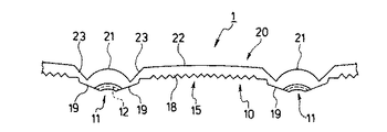
図1は実施形態の光学レンズの側面図、図2は長手方向に沿う縦断面図、図3は短手方向に沿う縦断面図、図4は背面図である。 1 is a side view of the optical lens of the embodiment, FIG. 2 is a longitudinal sectional view along the longitudinal direction, FIG. 3 is a longitudinal sectional view along the lateral direction, and FIG. 4 is a rear view.
本発明の光学レンズ(以下、「レンズ」と略称する)1は、光源にLEDを用いることを想定し、LED光源からの出射光が入射する光入射面を有する裏面10と、裏面10の反対側の面でレンズ1内を導光された光が出射する光出射面を有する表面20を備え、細長の形状を有している。
The optical lens (hereinafter abbreviated as “lens”) 1 of the present invention assumes that an LED is used as a light source, and is opposite to the
そのうち、裏面10には、LED光源からの出射光がレンズ1内に入射する光入射部11及びレンズ1内を導光中の光が内部反射(以下、「内部反射」は「全反射」を意味する)される光反射部15を有している。
Among them, on the
光入射部11は、レンズ1の面方向に垂直な直線Yに対して所定の角度θだけ短手方向に傾いた軸を主軸Xとする下方に凸の双曲線を、レンズ1の長手方向に沿って円弧状に延長した円弧状双曲面からなる第1光入射面12を有している。
The
また、第1光入射面12の、レンズ1の短手方向の一方の側には、第1光入射面12の双曲線の一方の上端から下方外側(第1光入射面12と反対側)に向けて延びる略直線を、レンズ1の長手方向に沿って円弧状に延長した扇状平面からなる第2光入射面13が形成され、第1光入射面12の、レンズ1の短手方向の他方の側には、第1光入射面12の双曲線の他方の上端から下方外側(第1光入射面12と反対側)に向けて延びる略直線を、レンズ1の長手方向に沿って円弧状に延長した扇状平面からなる第3光入射面14が形成されている。
Further, on one side of the first
更に、第2光入射面13の上端から外側(第1光入射面12と反対側)に延びる略直線を、レンズ1の長手方向に沿って円弧状に延長した扇状平面からなる第1光反射面16、及び第3光入射面14の上端から外側(第1光入射面12と反対側)に延びる略直線を、レンズ1の長手方向に沿って円弧状に延長した扇状平面からなる第2光反射面17が形成されている。
Further, the first light reflection is made of a fan-shaped plane in which a substantially straight line extending outward from the upper end of the second light incident surface 13 (on the side opposite to the first light incident surface 12) extends in an arc shape along the longitudinal direction of the
上記第1光入射面12、第2光入射面13及び第3光入射面14で構成される光入射部11は、第2光入射面13と第1光反射面16との交線、及び第3光入射面14と第2光反射面17との交線に対して凹んだ位置に形成されている。
The
光入射部11は、レンズ1の長手方向に所定の間隔を置いて複数箇所に設けられており、隣接する光入射部11同士の間には、短手方向に延びる三角柱18が長手方向に連続して平行に並設された光反射部15が形成されている。
The
光入射部11と光反射部15は、光入射部11から長手方向の隣接する光入射部11側に向かって斜め上方に傾斜する第1傾斜面19を介して接続されている。
The
光出射面20は、光入射部11の直上を上方に凸の円柱面からなる第1光出射面21とし、光反射部15の略反対側に位置する略平坦面を第2光出射面22としている。円柱面からなる第1光出射面21は、直下の円弧状双曲面からなる第1光入射面12に対して、互いの中心を結ぶ線がレンズ1の面方向に垂直な線となる位置関係にある。
The
第1光出射面21と第2光出射面22は、第1光出射面21の下端から長手方向の隣接する第1光出射面21側に向かって斜め上方に傾斜する第2傾斜面23を介して接続されている。
The first
上記構成のレンズ1は、図5(導光板に対するレンズの取り付け説明図)にあるように、導光板30の端部31に取り付け、LED光源から出射されてレンズ1によって導光・光路制御された光を導光板30内に導入するものである。導光板30は、全面に亘って厚みがほぼ均一な平板状をなしており、端面31aの形状はレンズ1の表面20の形状に沿った形状を有しており、レンズ1の表面20が導光板30の端面31aに嵌合した状態で、導光板30に保持される。
The
図6及び図7は、導光板30にレンズ1を取り付けた状態を示しており、図6は導光板30の面方向から見た図、図7は導光板30の厚み方向から見た図である。
6 and 7 show a state in which the
また、導光板30は、レンズ1の面方向に垂直な方向(厚み方向)に対して所定の角度だけ短手方向に傾いて配置されている。この場合、導光板30の厚み方向の中心軸Dと、円弧状双曲面からなる第1光入射面12の主軸Xとは、レンズ1の面方向に垂直な直線Yに対して互いに反対方向に傾いている(図7参照)。
The
なお、LED光源2は、導光板30の面方向から見た場合、円柱面からなる第1光出射面21の中心と円弧状双曲面からなる第1光入射面12の中心を結ぶ線Pの線上に配置され、導光板30の厚み方向から見た場合、円弧状双曲面からなる第1光入射面12の主軸X上の焦点位置に配置される。
Note that the
図8及び図9は、導光板にレンズを取り付けた状態における、LED光源2から出射された光の光線追跡のシミュレーション結果である。図8は上記図6と同様に導光板30の面方向から見た図であり、図9は図7と同様に導光板30の厚み方向から見た図である。
8 and 9 are simulation results of ray tracing of light emitted from the LED
図8より、LED光源2から出射されて第1光入射面12からレンズ1内に放射状に入射した光のうち、第1光出射面21に向かう光L1は放射状にレンズ1内を導光されて第1光出射面21に至り、該第1光出射面21及び、導光板30の、第1光出射面21の形状に沿った形状の端面31aを介して導光板30内に入射し、レンズ1内を導光された光が屈折することなくそのまま導光板30内を放射状に導光される。したがって、LED光源2から出射された光が導光板30の面方向に対してLED光源2を中心とする放射状に広がり、導光板30の広範囲の領域にまで届くことになる。
As shown in FIG. 8, among the light emitted from the LED
また、LED光源2から出射されて第1光入射面12からレンズ1内に放射状に入射した光のうち、第2光出射面22に向かう光L2はレンズ1内を導光されて第2光出射面22に至る。第2光出射面22に至った光は、該第2光出射面22で内部反射されて光反射部15の三角柱18の第3光反射面18aで内部反射されて反射光が導光板30内を導光されて第2光出射面22及び導光板30の端面31aを介して導光板30内に入射する。
Of the light emitted from the LED
あるいは、第2光出射面22に至った光は、該第2光出射面22で内部反射されて光反射部15の三角柱18の第3光反射面18aと第2光出射面22との間で内部反射を繰り返しながら第2光出射面22及び導光板30の端面31aを介して導光板30内に入射する。
Alternatively, the light that reaches the second
このように、LED光源2から出射されて第1光入射面12からレンズ1内に入射して第2光出射面22に向かう光L2は、該第2光出射面22から導光板30の端面31aを介して導光板30内に入射するものとなり、導光板30の、隣接する夫々の第1光出射面21からの出射光L1が到達する領域同士の間の領域に配光される。
As described above, the light L2 emitted from the LED
したがって、導光板30の面方向に対しては、光L1と光L2が互いの届かない領域を補完することにより導光板30の全面に亘って光の配光が施されるよう、レンズ1によって必要な光路制御が行われる
Therefore, with respect to the surface direction of the
一方、図9より、LED光源2から出射されて円弧状双曲面からなる第1光入射面12に照射された光L3は、該第1光入射面12で集光されて主軸Xに沿ってレンズ1内を導光され、第1光出射面21及び導光板30の端面31aを介してレンズ1内を導光された全ての光が導光板30内に入射される。
On the other hand, as shown in FIG. 9, the light L3 emitted from the LED
この場合、導光板30は、一方の面が光出射面32であり他方の面(裏面)33がシボ加工等による光拡散面となっており、且つ円弧状双曲面からなる第1光入射面12の主軸Xに対して傾けた状態に配置されている。そのため、端面31aを介して導光板30内に入射した光は、導光板30内を導光されて直接導光板30に光出射面32に至り、一部がそのまま光出射面32から外部に出射されると共にそれ以外は内部反射されて光拡散面の裏面33側に向かい、裏面33と光出射面32との間で内部反射を繰り返しながら光出射面32を介して外部に出射される。
In this case, the
また、LED光源2から出射されて第2光入射面13に照射された光L4は、第2光入射面13からレンズ1内に入射してレンズ1内を導光されて第1光反射面16で内部反射され、反射光が導光板30内を導光されて第1光出射面21及び導光板30の端面31aを介して導光板30内に入射される。導光板30内に入射した光は、上記同様に、裏面33と光出射面32との間で内部反射を繰り返しながら光出射面32を介して外部に出射される。
Further, the light L4 emitted from the LED
このように、LED光源2から出射されて第1光入射面12からレンズ1内に入射した光L3及び第2光入射面13からレンズ1内に入射した光L4は、いずれもそのほとんどが導光板30内に入射する。したがって、LED光源2からの出射光が効率良く導光板30内に導入されて光の利用効率が高められる。
Thus, most of the light L3 emitted from the LED
以上の構成により、LED光源2から出射されてレンズ1で光路制御された光を取り込んだ導光板30は光出射面32において、レンズ1の長手方向の光路制御によって光出射面32の広範囲に亘って発光領域が形成され、レンズ1の短手方向の光路制御によって光出射面32の発光領域の高輝度化が図られる。
With the above configuration, the
なお、レンズ1及び導光板30は互いに同一の透明材料で形成されることが好ましいが、必ずしも同一材料に限られるものではない。その場合は、屈折率が同一の材料あるいは互いの屈折率がほぼ同一の材料が好ましい。
The
上記実施形態においては、導光板30の厚み方向の中心軸Dと円弧状双曲面からなる第1光入射面12の主軸Xとは、レンズ1の面方向に垂直な直線Yに対して互いに反対方向に傾いた状態としたが、必ずしもこれに限られるものではなく、例えば、導光板30の厚み方向の中心軸D及び第1光入射面12の主軸Xが、レンズ1の面方向に垂直な直線Yに対して同一方向となる状態にあってもかまわない。この場合においても、レンズ1による光路制御の光学的な効果は充分に発揮される。
In the above embodiment, the central axis D in the thickness direction of the
1… 光学レンズ
2… LED光源
10… 裏面
11… 光入射部
12… 第1光入射面
13… 第2光入射面
14… 第3光入射面
15… 光反射部
16… 第1光反射面(全反射面)
17… 第2光反射面(全反射面)
18… 三角柱
18a… 第3光反射面(全反射面)
19… 第1傾斜面
20… 表面
21… 第1光出射面
22… 第2光出射面
23… 第2傾斜面
30… 導光板
31… 端部
31a… 端面
32… 光出射面
33… 裏面
DESCRIPTION OF
17 ... Second light reflection surface (total reflection surface)
18 ...
DESCRIPTION OF
Claims (6)
前記光学レンズは細長形状を有し、且つ裏面側と表面側の互いに対向する位置の夫々に光入射部と光出射部が設けられると共に前記光入射部と前記光出射部が長手方向に所定の間隔で複数箇所に設けられており、
前記光入射部は、前記レンズの厚み方向に延びる軸を主軸とする凸状の双曲線を前記レンズの長手方向に沿って円弧状に延長した凹円弧状双曲面からなる第1光入射面と、前記第1光入射面の前記レンズの短手方向の両側に位置し、前記双曲線の両端の夫々から下方外側に延びる直線を前記レンズの長手方向に沿って円弧状に延長した扇状平面からなる一対の第2光入射面を備え、
前記光出射部は、前記レンズの短手方向に延長された凸円柱面からなる第1光出射面を備えていることを特徴とする光学レンズ。 The light guide plate is disposed between a light source and a light guide plate that guides light incident from an end face and emits the light from a light exit surface on a surface to perform planar control of the light emitted from the light source. An optical lens that is incident on the light guide plate from the end face of
The optical lens has an elongated shape, and a light incident portion and a light emitting portion are provided at positions opposite to each other on the back surface side and the front surface side, and the light incident portion and the light emitting portion are predetermined in the longitudinal direction. It is provided at multiple locations at intervals,
The light incident portion includes a first light incident surface composed of a concave arc hyperboloid obtained by extending a convex hyperbola having an axis extending in the thickness direction of the lens as a main axis in an arc shape along the longitudinal direction of the lens; A pair of fan-shaped planes, which are located on both sides of the first light incident surface in the lateral direction of the lens and extend straight outwardly from both ends of the hyperbola in an arc shape along the longitudinal direction of the lens. A second light incident surface of
The optical lens, wherein the light emitting portion includes a first light emitting surface formed of a convex cylindrical surface extending in a short direction of the lens.
Priority Applications (1)
| Application Number | Priority Date | Filing Date | Title |
|---|---|---|---|
| JP2013056657A JP6073718B2 (en) | 2013-03-19 | 2013-03-19 | Optical lens |
Applications Claiming Priority (1)
| Application Number | Priority Date | Filing Date | Title |
|---|---|---|---|
| JP2013056657A JP6073718B2 (en) | 2013-03-19 | 2013-03-19 | Optical lens |
Publications (2)
| Publication Number | Publication Date |
|---|---|
| JP2014182939A JP2014182939A (en) | 2014-09-29 |
| JP6073718B2 true JP6073718B2 (en) | 2017-02-01 |
Family
ID=51701452
Family Applications (1)
| Application Number | Title | Priority Date | Filing Date |
|---|---|---|---|
| JP2013056657A Active JP6073718B2 (en) | 2013-03-19 | 2013-03-19 | Optical lens |
Country Status (1)
| Country | Link |
|---|---|
| JP (1) | JP6073718B2 (en) |
Families Citing this family (8)
| Publication number | Priority date | Publication date | Assignee | Title |
|---|---|---|---|---|
| JP6765055B2 (en) * | 2016-08-19 | 2020-10-07 | パナソニックIpマネジメント株式会社 | lighting equipment |
| JP2018063788A (en) * | 2016-10-11 | 2018-04-19 | 株式会社エンプラス | Luminous flux control member, light emitting device, surface light source device and display device |
| KR101922655B1 (en) * | 2016-12-21 | 2018-11-27 | 주식회사 뷰닉스 | The optical lens and mold having pattern and stepped structure |
| JP7390546B2 (en) | 2019-08-08 | 2023-12-04 | パナソニックIpマネジメント株式会社 | Optical systems, lighting systems, display systems and moving objects |
| EP3961292A4 (en) | 2019-04-26 | 2022-06-22 | Panasonic Intellectual Property Management Co., Ltd. | Optical system, illumination system, display system, and mobile body |
| JP7365628B2 (en) * | 2019-08-08 | 2023-10-20 | パナソニックIpマネジメント株式会社 | Optical components, optical systems, lighting systems, display systems, and moving objects |
| JPWO2021251043A1 (en) * | 2020-06-11 | 2021-12-16 | ||
| CN116293511A (en) * | 2021-12-21 | 2023-06-23 | 常州星宇车灯股份有限公司 | Light guide device and light emitting system |
Family Cites Families (4)
| Publication number | Priority date | Publication date | Assignee | Title |
|---|---|---|---|---|
| JP3025052B2 (en) * | 1991-05-31 | 2000-03-27 | 積水化学工業株式会社 | Mounting structure for eave gutter panels |
| JP2001236811A (en) * | 2000-02-23 | 2001-08-31 | Fujitsu Kasei Kk | Illumination device |
| JP5518559B2 (en) * | 2010-04-22 | 2014-06-11 | スタンレー電気株式会社 | Lamp unit |
| JP2012230914A (en) * | 2012-07-25 | 2012-11-22 | Sharp Corp | Light-emitting device |
-
2013
- 2013-03-19 JP JP2013056657A patent/JP6073718B2/en active Active
Also Published As
| Publication number | Publication date |
|---|---|
| JP2014182939A (en) | 2014-09-29 |
Similar Documents
| Publication | Publication Date | Title |
|---|---|---|
| JP6073718B2 (en) | Optical lens | |
| JP5315503B2 (en) | Lighting device | |
| JP5518559B2 (en) | Lamp unit | |
| JP6157456B2 (en) | lighting equipment | |
| JP6709095B2 (en) | Vehicle lighting | |
| JP2015513791A (en) | Optical element for uniform illumination | |
| JP2010224089A (en) | Prism | |
| JP6222557B2 (en) | Vehicle lighting | |
| JP6587849B2 (en) | Light guide lens and lamp | |
| JP6507035B2 (en) | Light flux control member, light emitting device and lighting device | |
| JP2015118907A (en) | Light guide device | |
| JP4660654B1 (en) | Lighting equipment | |
| JP5216431B2 (en) | Strobe reflector for camera | |
| JP2015125825A5 (en) | Illumination device and optical member | |
| JP6437252B2 (en) | Luminous flux control member, light emitting device, and illumination device | |
| JP2006332638A (en) | Light emitting diode apparatus | |
| US20160245973A1 (en) | Light guiding rod and illumination device including the same | |
| JP6129602B2 (en) | Document reading light source device | |
| KR20160074371A (en) | Diffusion lens aeembly and light emitting device comprising the same | |
| JP2016024855A (en) | Vehicular signal lamp | |
| JP2016045306A (en) | Light flux control member, plane light source device and display device | |
| JP2016018893A (en) | Light-emitting device | |
| JP2012145829A (en) | Light-emitting device and luminaire | |
| JP2016186884A (en) | Transparent material and light emitting device | |
| TWI531843B (en) | Light emitting module and backlight module using the same |
Legal Events
| Date | Code | Title | Description |
|---|---|---|---|
| A621 | Written request for application examination |
Free format text: JAPANESE INTERMEDIATE CODE: A621 Effective date: 20160219 |
|
| TRDD | Decision of grant or rejection written | ||
| A977 | Report on retrieval |
Free format text: JAPANESE INTERMEDIATE CODE: A971007 Effective date: 20161130 |
|
| A01 | Written decision to grant a patent or to grant a registration (utility model) |
Free format text: JAPANESE INTERMEDIATE CODE: A01 Effective date: 20161206 |
|
| A61 | First payment of annual fees (during grant procedure) |
Free format text: JAPANESE INTERMEDIATE CODE: A61 Effective date: 20170105 |
|
| R150 | Certificate of patent or registration of utility model |
Ref document number: 6073718 Country of ref document: JP Free format text: JAPANESE INTERMEDIATE CODE: R150 |
|
| R250 | Receipt of annual fees |
Free format text: JAPANESE INTERMEDIATE CODE: R250 |
|
| R250 | Receipt of annual fees |
Free format text: JAPANESE INTERMEDIATE CODE: R250 |
|
| R250 | Receipt of annual fees |
Free format text: JAPANESE INTERMEDIATE CODE: R250 |
|
| R250 | Receipt of annual fees |
Free format text: JAPANESE INTERMEDIATE CODE: R250 |
|
| R250 | Receipt of annual fees |
Free format text: JAPANESE INTERMEDIATE CODE: R250 |