JP6073059B2 - High frequency current provider and method for surgical instruments - Google Patents
High frequency current provider and method for surgical instruments Download PDFInfo
- Publication number
- JP6073059B2 JP6073059B2 JP2011525424A JP2011525424A JP6073059B2 JP 6073059 B2 JP6073059 B2 JP 6073059B2 JP 2011525424 A JP2011525424 A JP 2011525424A JP 2011525424 A JP2011525424 A JP 2011525424A JP 6073059 B2 JP6073059 B2 JP 6073059B2
- Authority
- JP
- Japan
- Prior art keywords
- power
- current
- frequency current
- surgical instrument
- voltage
- Prior art date
- Legal status (The legal status is an assumption and is not a legal conclusion. Google has not performed a legal analysis and makes no representation as to the accuracy of the status listed.)
- Expired - Fee Related
Links
Images


Classifications
-
- A—HUMAN NECESSITIES
- A61—MEDICAL OR VETERINARY SCIENCE; HYGIENE
- A61B—DIAGNOSIS; SURGERY; IDENTIFICATION
- A61B18/00—Surgical instruments, devices or methods for transferring non-mechanical forms of energy to or from the body
- A61B18/04—Surgical instruments, devices or methods for transferring non-mechanical forms of energy to or from the body by heating
- A61B18/12—Surgical instruments, devices or methods for transferring non-mechanical forms of energy to or from the body by heating by passing a current through the tissue to be heated, e.g. high-frequency current
- A61B18/1206—Generators therefor
-
- H—ELECTRICITY
- H03—ELECTRONIC CIRCUITRY
- H03L—AUTOMATIC CONTROL, STARTING, SYNCHRONISATION, OR STABILISATION OF GENERATORS OF ELECTRONIC OSCILLATIONS OR PULSES
- H03L5/00—Automatic control of voltage, current, or power
-
- A—HUMAN NECESSITIES
- A61—MEDICAL OR VETERINARY SCIENCE; HYGIENE
- A61B—DIAGNOSIS; SURGERY; IDENTIFICATION
- A61B18/00—Surgical instruments, devices or methods for transferring non-mechanical forms of energy to or from the body
- A61B2018/00571—Surgical instruments, devices or methods for transferring non-mechanical forms of energy to or from the body for achieving a particular surgical effect
- A61B2018/00577—Ablation
-
- A—HUMAN NECESSITIES
- A61—MEDICAL OR VETERINARY SCIENCE; HYGIENE
- A61B—DIAGNOSIS; SURGERY; IDENTIFICATION
- A61B18/00—Surgical instruments, devices or methods for transferring non-mechanical forms of energy to or from the body
- A61B2018/00571—Surgical instruments, devices or methods for transferring non-mechanical forms of energy to or from the body for achieving a particular surgical effect
- A61B2018/00601—Cutting
-
- A—HUMAN NECESSITIES
- A61—MEDICAL OR VETERINARY SCIENCE; HYGIENE
- A61B—DIAGNOSIS; SURGERY; IDENTIFICATION
- A61B18/00—Surgical instruments, devices or methods for transferring non-mechanical forms of energy to or from the body
- A61B2018/00636—Sensing and controlling the application of energy
- A61B2018/00642—Sensing and controlling the application of energy with feedback, i.e. closed loop control
-
- A—HUMAN NECESSITIES
- A61—MEDICAL OR VETERINARY SCIENCE; HYGIENE
- A61B—DIAGNOSIS; SURGERY; IDENTIFICATION
- A61B18/00—Surgical instruments, devices or methods for transferring non-mechanical forms of energy to or from the body
- A61B2018/00636—Sensing and controlling the application of energy
- A61B2018/00696—Controlled or regulated parameters
- A61B2018/00767—Voltage
-
- A—HUMAN NECESSITIES
- A61—MEDICAL OR VETERINARY SCIENCE; HYGIENE
- A61B—DIAGNOSIS; SURGERY; IDENTIFICATION
- A61B18/00—Surgical instruments, devices or methods for transferring non-mechanical forms of energy to or from the body
- A61B2018/00636—Sensing and controlling the application of energy
- A61B2018/00773—Sensed parameters
- A61B2018/00892—Voltage
Description
本発明は、請求項1の導入部に記載の手術器用高周波発生器、および手術器用高周波発生器における高周波電圧発生方法に関する。 The present invention relates to a high-frequency generator for a surgical instrument according to the introduction part of claim 1 and a high-frequency voltage generation method in the high-frequency generator for a surgical instrument.
外科手術用高周波装置は、外科手術においてますます利用されるようになってきている。この目的のために使用される発生器は、一般的に300kHz〜4MHzの範囲にある基本周波数を供給する。発生器には、電力発振器が設けられ、幹線電力網から供給され、整流された電気エネルギを、前述の基本周波数を有する、電位フリー、直流電圧フリーの出力電圧へ変換する。高電圧での凝固、あるいは凝固併用切断などのような非常に多くの応用事例において、この周波数は、一般的に50kHzのオ−ダの「変調周波数」で重畳される。限られた数の正弦波発振、極端な場合には、単一の正弦波発振が生成され、エネルギ伝搬のないパルス中断がその後に続く。変調期間が終了すると、パルスパケットの供給が再開される。 Surgical radio frequency devices are increasingly being used in surgery. The generator used for this purpose provides a fundamental frequency that is generally in the range of 300 kHz to 4 MHz. The generator is provided with a power oscillator, and converts the rectified electric energy supplied from the main power grid into a potential-free and DC voltage-free output voltage having the above-described fundamental frequency. In very many applications, such as high voltage coagulation or coagulation cutting, this frequency is superimposed on a “modulation frequency”, typically on the order of 50 kHz. A limited number of sinusoidal oscillations, in the extreme case a single sinusoidal oscillation, is generated, followed by a pulse break without energy propagation. When the modulation period ends, the supply of pulse packets is resumed.
このことから、出力電圧の瞬時開始が要請されることは明白である。1半周期、あるいは長くとも2半周期の後に、出力電圧は、最終値に到達していなければならず、それが、処置する組織に求めようとしている効果に影響を及ぼす。 From this it is clear that an instantaneous start of the output voltage is required. After one half cycle or at most two half cycles, the output voltage must have reached its final value, which affects the effect sought for the tissue to be treated.
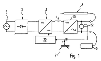
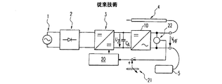
通常、上記のエネルギ変換は、図7に示すように、連続する2つのステップで実現される。第1に、幹線1から供給される電気エネルギは、整流器2で整流され、一定の直流電圧が得られるようになる。この直流定電圧は、電源3(直流/直流コンバータ)によって、中間的な回路電圧UZに変換される。この中間回路電圧UZは、調整可能である。この第1のエネルギ変換ユニットを、以下では電源と称する。
Normally, the energy conversion described above is realized in two successive steps as shown in FIG. First, the electrical energy supplied from the main line 1 is rectified by the
そこへ第2のエネルギ変換ユニットが接続され、これは、以下では電力発振器10と称する。電力発振器10は、インバータであり、患者の回路からの電位分離機能も含む。電力発振器10の出力端子は、一方が電気手術器4に、もう一方が中性電極5に接続される。また、この電力発振器10の出力端子には、実効値センサ22も接続されており、電力発振器10の出力における電圧を検知し、この電圧を設定値発生器21からの目標電圧と比較する。そうして、システムの偏差がコントローラ20を介して電源3にフィードバックされ、電力発振器10の出力電圧振幅が設定値発生器21の設定に従って制御されるように、中間回路電圧UZが調節される。
Thereto a second energy conversion unit is connected, which is hereinafter referred to as
図8、9に示すように、電力発振器10は通常、パワー半導体装置を有する駆動回路11と、変圧器12(これは並列に接続されたコンデンサCPとで並列共振回路となっているが)と、変圧器12の出力側にある、患者の回路に対して直列共振回路となる、コイルLSAとコンデンサCSAとを含む直列回路と、を含む。図9に示す従来の実施形態においては、駆動回路11の出力端子と、変圧器12と並列コンデンサCPとで構成される並列共振回路との間に、コイルLSEとコンデンサCSEとで構成される直列共振回路をさらに含む。
8 and 9, the
最高の変調機能を確保し、従って出力電圧の発振が瞬時に開始されるようにするために、入力直列共振回路(図9のような)は、省略されることが多い(図8に示すように)。全体の共振回路の入力は、従って並列共振回路である。駆動回路もまた電圧源、特に電源3の出力コンデンサCAからの供給を受けているので、駆動パワー半導体装置11は、充電されたコンデンサ(CA)と未充電コンデンサ(CP)との間での短絡を表している。その結果、流れる電流の大きさは、半導体回路の導線インダクタンスや経路抵抗などのような寄生的なものの発現によってのみ決定される。これらの寄生値は、実際の部品の値に比べて通常小さいので、非常に大きな不確定の電流値が生じる。この、しばしば非常に高いパルス電流は、望ましくない(病院環境においては許容されないような)電磁干渉を放射する可能性がある。さらには、駆動回路11のパワー半導体装置の容量が経済的でないことが多い。
The input series resonant circuit (as in FIG. 9) is often omitted (as shown in FIG. 8) in order to ensure the best modulation function, and so that oscillation of the output voltage starts instantaneously. To). The input of the entire resonant circuit is therefore a parallel resonant circuit. Driving circuit is also a voltage source, since in particular supplied from the output capacitor C A power supply 3, driving the
この課題を解決するために、図9に示す、駆動電流が入力インダクタンスLSEによって決定される回路が利用される。しかし、この回路では、フィルタが瞬時に発振開始しないという欠点が生じ、従って前述の変調に対しては好適ではない。 In order to solve this problem, the circuit shown in FIG. 9 in which the drive current is determined by the input inductance LSE is used. However, this circuit has the disadvantage that the filter does not start oscillating instantaneously and is therefore not suitable for the modulation described above.
本発明の目的は、良好な変調機能が実現でき、前述の不利な点、とりわけ過電流が防止できるような、手術器用高周波発生器、および手術器用高周波発生器における高周波電圧発生方法を提供することにある。 An object of the present invention is to provide a high-frequency generator for a surgical instrument and a high-frequency voltage generation method in the high-frequency generator for a surgical instrument that can realize a favorable modulation function and can prevent the above-described disadvantages, particularly overcurrent. It is in.
この目的は、請求項1による手術器用高周波発生器と、請求項11による方法とで達成される。
This object is achieved with a high-frequency generator for a surgical instrument according to claim 1 and a method according to
特に本目的は、整流された電気エネルギを供給するための電源と、電位フリー、直流電流フリー、または直流電圧フリーの高周波電圧を提供するための電力発振器と、高周波電圧を制御するための制御装置と、を備える手術器用高周波発生器であって、その電源は、負荷に依存しない出力電流を供給するための電流源として構成され、その目標値は、前記電源の負荷に依存しない出力電流が高周波電圧を制御するための制御変数として作用するように制御装置によって予め定められている、手術器用高周波発生器によって得られる。 Particularly, the present object is to provide a power source for supplying rectified electric energy, a power oscillator for providing a potential-free, direct current-free or direct-current-free high-frequency voltage, and a control device for controlling the high-frequency voltage. The power supply is configured as a current source for supplying an output current independent of the load, and the target value is a high-frequency output current independent of the load of the power supply. It is obtained by a high frequency generator for a surgical instrument that is predetermined by the control device to act as a control variable for controlling the voltage.
従って既知の方法と違って、本質的な特徴は、電源が負荷に依存しない出力電圧を持つのではなく、負荷に依存しない制御された出力電流を有する点にある。この出力電流の目標値は、(それ自体は既知の)外科手術器用高周波装置の制御システムによって前以って決定される。従って、負荷に依存しない電流は、高周波出力電圧および組織に及ぼす高周波の効果を制御するための制御変数として作用する。 Thus, unlike the known methods, the essential feature is that the power supply does not have a load-independent output voltage but has a load-independent controlled output current. This target value of the output current is determined in advance by the control system of the surgical instrument radio frequency device (known per se). Thus, the load independent current acts as a control variable for controlling the high frequency output voltage and the effect of the high frequency on the tissue.
この電源は、好ましくは、幹線交流電圧を本質的に一定な直流電圧へ変換するための幹線整流装置と、調整可能な整流エネルギを供給するための出力側に接続された中間回路と、を備える。電源は、好ましくは、降圧コンバータ、又は電位分離順方向コンバータのいずれかを備える。この場合には、出力コンデンサは、含まれない。従って、電源の出力は、インダクタンスであり、電源の制御システムは、出力電流を制御する。ここで、出力電圧は、負荷の状況に応じて自由に調節可能である。 The power supply preferably comprises a main rectifier for converting the main AC voltage to an essentially constant DC voltage, and an intermediate circuit connected to the output for supplying adjustable rectified energy. . The power supply preferably comprises either a step-down converter or a potential separation forward converter. In this case, the output capacitor is not included. Therefore, the output of the power supply is an inductance, and the control system of the power supply controls the output current. Here, the output voltage can be freely adjusted according to the load condition.
本明細書で必要とされる電流制御システムで制御されるシステムは、少なくとも、構造的な大きさ/費用と電流リップルとの間の折り合いを反映した好適な出力インダクタンスの選択をした後には、非常に速い時定数を持つので、電流コントローラは、好適には“有限の調節時間を有する制御システム”として実現され、さらに好ましくは、特にデジタル信号プロセッサまたは他の集積回路における「デッドビート制御器」として実現される。 The system controlled by the current control system required herein will be at least after selecting a suitable output inductance that reflects the tradeoff between structural size / cost and current ripple. The current controller is preferably implemented as a “control system with a finite adjustment time”, more preferably as a “deadbeat controller”, especially in digital signal processors or other integrated circuits. Realized.
これに関連して、電力が配電されていない電源の状態は、出力において短絡状態であるということに留意されたい。従って、この装置は、短絡に耐えられるものである。負荷なしで運転している時は、誘導過電圧によって部品が破壊するまで電圧が上昇する可能性がある。従って、(電力発振器の)下流の回路部品の動作によって、電源の誘導出力が決して負荷なしで運転されることがないようにされなければならない。 In this connection, it should be noted that the state of the power supply that is not distributing power is a short circuit condition at the output. Therefore, this device can withstand short circuits. When operating without a load, the voltage may rise until the part is destroyed by induced overvoltage. Therefore, the operation of downstream circuit components (of the power oscillator) must ensure that the inductive output of the power supply is never operated without a load.
電力発振器は、好ましくは、半導体回路要素のHブリッジとして構成されたパワーエレクトロニクス駆動回路を備える。負荷なしでの運転中に、望ましくない電力の短絡を防ぐために、好ましくは、半導体回路要素にダイオードが直列に設けられる。 The power oscillator preferably comprises a power electronics drive circuit configured as an H-bridge of semiconductor circuit elements. A diode is preferably provided in series with the semiconductor circuit element to prevent undesired power shorts during operation without a load.
駆動回路は、好ましくは、エネルギ回復操作において、リアクタンス部品に蓄積されたエネルギが電源にフィードバックされ、回路構成の効率が向上するように構成されている。さらに、エネルギの回復によって、出力電圧の後振動が防止され、出力電圧の曲線形状が可及的速やかにゼロに減少する。 The drive circuit is preferably configured so that the energy stored in the reactance component is fed back to the power source in the energy recovery operation, and the efficiency of the circuit configuration is improved. In addition, energy recovery prevents post-vibration of the output voltage and reduces the output voltage curve shape to zero as quickly as possible.
また、駆動回路は、好ましくは、半導体回路要素がふたつひと組で、位相同期共振の形で制御される。2*50%の比較的高速のスイッチング時間であるために、パワー半導体部品には中間的な電流強度が生成され、これが非常に好都合に利用される。 Also, the drive circuit is preferably controlled in the form of a phase-locked resonance with two pairs of semiconductor circuit elements. Due to the relatively fast switching time of 2 * 50%, an intermediate current strength is generated in the power semiconductor component, which is used very advantageously.
エネルギ回復能力なしで済む場合には、パワー半導体装置を(4つと比べて)2つ割愛することができる。電力供給に関しては、相互に独立して制御される2つの電流源(電源)を構築するか、あるいは、1つの電流制限された電源を回路に供給して、誘導電流分割器により2つに分岐するかのいずれかである。 If there is no need for energy recovery capability, two power semiconductor devices can be omitted (compared to four). Concerning power supply, two current sources (power supplies) controlled independently of each other are constructed, or one current limited power supply is supplied to the circuit and branched into two by an inductive current divider Is either
本発明による、手術器用高周波発生器に高周波電圧を発生させる方法は、電源に整流された電気エネルギを生成するステップと、電位フリー、直流電流フリー、または直流電圧フリーの制限された高周波電圧を生成するステップとを含み、この電源は、電源の負荷に依存しない出力電流が制御変数として高周波電圧を制限するように、所定の目標値を有する負荷に依存しない出力電流を供給する。 According to the present invention, a method for generating a high-frequency voltage in a high-frequency generator for a surgical instrument includes a step of generating rectified electrical energy to a power source, and generating a limited high-frequency voltage free of potential, direct current, or direct voltage The power supply supplies a load-independent output current having a predetermined target value such that the output current independent of the load of the power supply limits the high-frequency voltage as a control variable.
本発明の好適な実施形態は、複数の従属請求項と以下の例示的実施形態の説明において開示される。その詳細を次に図面を参照して説明する。 Preferred embodiments of the invention are disclosed in the dependent claims and in the following description of exemplary embodiments. Details thereof will be described with reference to the drawings.
以下の説明においては、同一および類似の作用をする部品に関しては同一の参照符号および表示を用いている。 In the following description, the same reference numerals and symbols are used for parts having the same and similar functions.
本明細書で説明し図1に示す手術器用高周波発生器の例示的実施形態の基本構造は、図7〜9を参照して説明されている従来技術に、本質的に対応するものである。しかしながら、電源3には本質的な違いがある。従来技術では、出力に並列に接続されたコンデンサCAに定電圧UZを与えるのに対し、本発明による電源3は、出力インダクタンスLAを介して、負荷に依存しない出力電流を電力発振器10に供給する。 The basic structure of the exemplary embodiment of the surgical high-frequency generator described herein and shown in FIG. 1 essentially corresponds to the prior art described with reference to FIGS. However, the power supply 3 has an essential difference. In the prior art, while providing a constant voltage U Z to the capacitor C A connected in parallel with the output, the power source 3 according to the invention, via the output inductance L A, power oscillator 10 the output current that is independent of the load To supply.
図2Aは、電源3の第1の実施形態を示し、この電源は、出力側にフィルターコンデンサを有する整流器2から一定の入力直流電圧を受取る。この電源3は、降圧コンバータとして設計されていて(出力側にコンデンサを持たないが)、スイッチングトランジスタT1とダイオードとの直列接続で構成される。その接続点に、電力発振器10が出力インダクタンスLAを介して結合される。電流は、実効値センサ22’通って、減算回路へ流れ、そこでこの実効電流値が、前述の既知のコントローラ20から来る目標電流値と比較される。この比較値がシステムの偏差を表し、コントローラ20’に通知される。このコントローラがトランジスタT1を制御して、所望の出力電流を設定する。
FIG. 2A shows a first embodiment of a power supply 3, which receives a constant input DC voltage from a
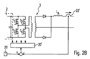
図2Bに示す電源3の一変形は、それ自体は既知の、電位分離電流コンバータである。この場合には、4つのスイッチングトランジスタT1、T2、T3、T4が設けられ、H型回路を構成している。各変圧器の一次巻線は、トランジスタT1とT3、およびT2とT4のそれぞれの接続点に接続され、相互に結合する変圧器の二次巻線は、ダイオードを介して出力インダクタンスLAに接続されている。二次巻線の接続点が、電源3の第2の出力端子を形成する。図2Aによる場合と同様に制御が実行される。 A variant of the power supply 3 shown in FIG. 2B is a potential separation current converter known per se. In this case, four switching transistors T 1 , T 2 , T 3 , and T 4 are provided to form an H-type circuit. The primary winding of each transformer is connected to the respective connection points of transistors T 1 and T 3 , and T 2 and T 4 , and the secondary winding of the transformer that couples to each other is connected to the output inductance via a diode. It is connected to the L a. The connection point of the secondary winding forms the second output terminal of the power supply 3. Control is executed in the same manner as in FIG. 2A.
次に、電力発振器用駆動回路のパワーエレクトロニクスについて、図3、4を参照して説明する。 Next, power electronics of the power oscillator drive circuit will be described with reference to FIGS.
電力発振器11は、Γフィルタとして構成されている。図3によれば、駆動回路のパワーエレクトロニクスは、2つのトランジスタの組T1oとT1u、T2oとT2uを有するHブリッジとして構成されている。そして、負荷フリーの動作中における、望ましくない負荷の短絡を防止するために、パワートランジスタと直列にダイオードが設けられている。トランジスタの組(T1oとT1u、T2oとT2u)の接続点へは、コンデンサCPを並列に有する変圧器12の一次巻線が接続される。変圧器12の出力、即ち二次巻線には、出力直列共振回路LSAとCSAが接続される。変圧器12の二次巻線と共に、この直列共振回路には患者の電流回路部分が含まれる。
The
この回路の動作は、図4に示すように、2つの対角的に向き合ったパワー半導体装置がいつも同時に通電される。従って、H回路の出力側の並列共振回路に通電するために、トランジスタT1oとT2u、またはT2oとT1uに同時に電流を流す。負荷なしの状態で、電源から電力発振器へエネルギが出力されていない場合、ブリッジのそれぞれ半分であるT1oとT1u、またはT2oとT2uのいずれかが、同時にスイッチオンされることが必要である。 In the operation of this circuit, as shown in FIG. 4, two diagonally facing power semiconductor devices are always energized simultaneously. Therefore, in order to energize the parallel resonant circuit on the output side of the H circuit, a current is simultaneously supplied to the transistors T 1o and T 2u or T 2o and T 1u . If no power is being output from the power supply to the power oscillator in the absence of a load, either T 1o and T 1u , or T 2o and T 2u , each half of the bridge, must be switched on simultaneously It is.
第3の可能な動作モードは、4つのトランジスタ全てを同時にスイッチオンさせて、電力発振器11のリアクタンス部品中のエネルギを電源3の出力インダクタンスLAへエネルギ回復動作をさせる。このタイプのエネルギ回復で、出力電圧がポストパルス発振することが防止され、出力電圧曲線の形状が、可及的速やかにゼロとなる。
A third possible mode of operation, all four transistors is switched on at the same time, it makes the energy recovery operation of the energy in the reactive component of the
この回路はさらに、その容量で興味ある性質を有している。とりわけ、相対スイッチング時間(デューティサイクル)をほぼ100%として、この回路を駆動することが可能である。このためには、並列共振回路(12/CP)の電圧が正である限り、スイッチT1oとT2uとが閉じられる。これにより位相同期スイッチングが確保され、図4に示すようにこれによって回路が共振動作する。この相対的に大きなスイッチング時間2*50%は、パワー半導体部品に中程度の電流強度をもたらし、従って非常に経済的に利用される。 This circuit also has interesting properties due to its capacity. In particular, it is possible to drive this circuit with a relative switching time (duty cycle) of approximately 100%. For this purpose, the switches T 1o and T 2u are closed as long as the voltage of the parallel resonant circuit (12 / C P ) is positive. As a result, phase-synchronized switching is ensured, and the circuit resonates as shown in FIG. This relatively large switching time of 2 * 50% results in moderate current strength in the power semiconductor component and is therefore very economically utilized.
図5に示す電力発振器10の実施形態においては、2つの半導体部品T1、T2(と負荷フリー動作ダイオード)しかなく、この部品は相互に独立して制限される2つの電流源を有している。図6に示す変形例では、単一の電流制限電源しか与えられていないが、パワー半導体部品T1、T2を有する2つの分岐へ、誘導電流分割器を介して配電される。
In the embodiment of the
上記より、本発明は、多くの異なる回路構成で実現可能であることが明白である。 From the above, it is apparent that the present invention can be implemented with many different circuit configurations.
1 幹線
2 整流器
3 電源または直流/直流コンバータ
4 機器
5 中性電極
10 電力発振器
11 駆動回路
12 変圧器
20 コントローラ
21 設定値発生器
22 実効値検出器
DESCRIPTION OF SYMBOLS 1
Claims (6)
前記供給された電気エネルギに基づく高周波電流を手術器に提供するための電力発振器(10)と、
前記電源(3)から前記電力発振器(10)に供給される電流の値が所望の目標値となるように前記電源(3)の降圧コンバータを制御する制御装置(20)と、
を備える、手術器用高周波電流提供器。 A power supply (3) comprising a step-down converter for supplying rectified electrical energy;
A power oscillator (10) for providing a surgical device with a high-frequency current based on the supplied electrical energy ;
A control device (20) for controlling the step-down converter of the power source (3) so that the value of the current supplied from the power source (3) to the power oscillator (10) becomes a desired target value ;
A high-frequency current provider for a surgical instrument .
前記供給された電気エネルギに基づく電流を手術器に提供するための電力発振器(10)と、
制御装置(20)と、
を備える手術器用高周波電流提供器において、高周波電流を提供させる方法であって、
前記制御装置(20)が、前記電源(3)から前記電力発振器(10)に供給される電流の値が目標値となるように前記電源(3)の降圧コンバータを制御する、
ことを特徴とする、方法。 A power supply (3) comprising a step-down converter for supplying rectified electrical energy;
A power oscillator (10) for providing a current to the surgical instrument based on the supplied electrical energy;
A control device (20);
A high-frequency current provider for a surgical instrument comprising: a method for providing a high-frequency current,
The control device (20) controls the step-down converter of the power source (3) such that a value of a current supplied from the power source (3) to the power oscillator (10) becomes a target value;
A method characterized by that.
Applications Claiming Priority (5)
| Application Number | Priority Date | Filing Date | Title |
|---|---|---|---|
| DE102008046247.0 | 2008-09-08 | ||
| DE102008046247 | 2008-09-08 | ||
| DE102008058737.0A DE102008058737B4 (en) | 2008-09-08 | 2008-11-24 | Electrosurgical generator |
| DE102008058737.0 | 2008-11-24 | ||
| PCT/EP2009/005797 WO2010025807A1 (en) | 2008-09-08 | 2009-08-10 | Hf surgical generator |
Publications (3)
| Publication Number | Publication Date |
|---|---|
| JP2012501696A JP2012501696A (en) | 2012-01-26 |
| JP2012501696A5 JP2012501696A5 (en) | 2012-08-02 |
| JP6073059B2 true JP6073059B2 (en) | 2017-02-01 |
Family
ID=41161383
Family Applications (1)
| Application Number | Title | Priority Date | Filing Date |
|---|---|---|---|
| JP2011525424A Expired - Fee Related JP6073059B2 (en) | 2008-09-08 | 2009-08-10 | High frequency current provider and method for surgical instruments |
Country Status (7)
| Country | Link |
|---|---|
| US (1) | US9168083B2 (en) |
| EP (1) | EP2349041B1 (en) |
| JP (1) | JP6073059B2 (en) |
| CN (1) | CN102149345B (en) |
| DE (1) | DE102008058737B4 (en) |
| PL (1) | PL2349041T3 (en) |
| WO (1) | WO2010025807A1 (en) |
Families Citing this family (71)
| Publication number | Priority date | Publication date | Assignee | Title |
|---|---|---|---|---|
| EP1676108B1 (en) | 2003-10-23 | 2017-05-24 | Covidien AG | Thermocouple measurement circuit |
| US7396336B2 (en) | 2003-10-30 | 2008-07-08 | Sherwood Services Ag | Switched resonant ultrasonic power amplifier system |
| US7651492B2 (en) | 2006-04-24 | 2010-01-26 | Covidien Ag | Arc based adaptive control system for an electrosurgical unit |
| US8377053B2 (en) | 2008-09-05 | 2013-02-19 | Covidien Lp | Electrosurgical apparatus with high speed energy recovery |
| US8242782B2 (en) | 2008-09-30 | 2012-08-14 | Vivant Medical, Inc. | Microwave ablation generator control system |
| US8262652B2 (en) | 2009-01-12 | 2012-09-11 | Tyco Healthcare Group Lp | Imaginary impedance process monitoring and intelligent shut-off |
| US8617154B2 (en) | 2010-06-25 | 2013-12-31 | Covidien Lp | Current-fed push-pull converter with passive voltage clamp |
| US9379643B2 (en) * | 2010-12-23 | 2016-06-28 | The Regents Of The University Of Colorado, A Body Corporate | Electrosurgical generator controller for regulation of electrosurgical generator output power |
| KR102018928B1 (en) * | 2011-11-10 | 2019-09-05 | 애플 인크. | A method for controlling a converter |
| US10076383B2 (en) | 2012-01-25 | 2018-09-18 | Covidien Lp | Electrosurgical device having a multiplexer |
| US9037447B2 (en) | 2012-01-27 | 2015-05-19 | Covidien Lp | Systems and methods for phase predictive impedance loss model calibration and compensation |
| US9480523B2 (en) | 2012-01-27 | 2016-11-01 | Covidien Lp | Systems and methods for phase predictive impedance loss model calibration and compensation |
| WO2013134763A2 (en) | 2012-03-09 | 2013-09-12 | Enteromedics Inc. | Safety features for use in medical devices |
| US8968290B2 (en) | 2012-03-14 | 2015-03-03 | Covidien Lp | Microwave ablation generator control system |
| US8653994B2 (en) | 2012-03-21 | 2014-02-18 | Covidien Lp | System and method for detection of ADC errors |
| US9198711B2 (en) | 2012-03-22 | 2015-12-01 | Covidien Lp | Electrosurgical system for communicating information embedded in an audio tone |
| US9375250B2 (en) | 2012-04-09 | 2016-06-28 | Covidien Lp | Method for employing single fault safe redundant signals |
| US8932291B2 (en) | 2012-04-13 | 2015-01-13 | Covidien Lp | Electrosurgical systems |
| US9375249B2 (en) | 2012-05-11 | 2016-06-28 | Covidien Lp | System and method for directing energy to tissue |
| US9192424B2 (en) | 2012-05-31 | 2015-11-24 | Covidien Lp | AC active load |
| US9192425B2 (en) | 2012-06-26 | 2015-11-24 | Covidien Lp | System and method for testing electrosurgical generators |
| US9529025B2 (en) | 2012-06-29 | 2016-12-27 | Covidien Lp | Systems and methods for measuring the frequency of signals generated by high frequency medical devices |
| US9861425B2 (en) | 2012-10-02 | 2018-01-09 | Covidien Lp | System and method for using resonance phasing for measuring impedance |
| US9921243B2 (en) | 2012-12-17 | 2018-03-20 | Covidien Lp | System and method for voltage and current sensing |
| US9456862B2 (en) | 2013-02-19 | 2016-10-04 | Covidien Lp | Electrosurgical generator and system |
| US9895186B2 (en) | 2013-03-11 | 2018-02-20 | Covidien | Systems and methods for detecting abnormalities within a circuit of an electrosurgical generator |
| US9270202B2 (en) | 2013-03-11 | 2016-02-23 | Covidien Lp | Constant power inverter with crest factor control |
| US9519021B2 (en) | 2013-03-11 | 2016-12-13 | Covidien Lp | Systems and methods for detecting abnormalities within a circuit of an electrosurgical generator |
| US10842563B2 (en) | 2013-03-15 | 2020-11-24 | Covidien Lp | System and method for power control of electrosurgical resonant inverters |
| US9498276B2 (en) | 2013-03-15 | 2016-11-22 | Covidien Lp | Systems and methods for narrowband real impedance control in electrosurgery |
| US9283028B2 (en) | 2013-03-15 | 2016-03-15 | Covidien Lp | Crest-factor control of phase-shifted inverter |
| US9504516B2 (en) | 2013-05-31 | 2016-11-29 | Covidien LLP | Gain compensation for a full bridge inverter |
| US9559594B2 (en) * | 2013-06-24 | 2017-01-31 | Covidien Lp | Dead-time optimization of resonant inverters |
| US10729484B2 (en) | 2013-07-16 | 2020-08-04 | Covidien Lp | Electrosurgical generator with continuously and arbitrarily variable crest factor |
| US10610285B2 (en) * | 2013-07-19 | 2020-04-07 | Covidien Lp | Electrosurgical generators |
| US9872719B2 (en) | 2013-07-24 | 2018-01-23 | Covidien Lp | Systems and methods for generating electrosurgical energy using a multistage power converter |
| US10285750B2 (en) | 2013-07-29 | 2019-05-14 | Covidien Lp | Systems and methods for operating an electrosurgical generator |
| US9636165B2 (en) | 2013-07-29 | 2017-05-02 | Covidien Lp | Systems and methods for measuring tissue impedance through an electrosurgical cable |
| US9770283B2 (en) | 2013-09-24 | 2017-09-26 | Covidien Lp | Systems and methods for improving efficiency of electrosurgical generators |
| US9839469B2 (en) | 2013-09-24 | 2017-12-12 | Covidien Lp | Systems and methods for improving efficiency of electrosurgical generators |
| US10058374B2 (en) | 2013-09-26 | 2018-08-28 | Covidien Lp | Systems and methods for estimating tissue parameters using surgical devices |
| US9867651B2 (en) | 2013-09-26 | 2018-01-16 | Covidien Lp | Systems and methods for estimating tissue parameters using surgical devices |
| US10130412B2 (en) | 2013-09-26 | 2018-11-20 | Covidien Lp | Systems and methods for estimating tissue parameters using surgical devices |
| US10188446B2 (en) * | 2013-10-16 | 2019-01-29 | Covidien Lp | Resonant inverter |
| US10105172B2 (en) | 2013-10-16 | 2018-10-23 | Covidien Lp | Radiofrequency amplifier impedance optimization |
| US9913679B2 (en) | 2013-10-16 | 2018-03-13 | Covidien Lp | Electrosurgical systems and methods for monitoring power dosage |
| US9642670B2 (en) | 2013-10-29 | 2017-05-09 | Covidien Lp | Resonant inverter with a common mode choke |
| US9901385B2 (en) | 2014-01-13 | 2018-02-27 | Covidien Lp | Systems and methods for multifrequency cable compensation |
| US10492850B2 (en) | 2014-04-04 | 2019-12-03 | Covidien Lp | Systems and methods for calculating tissue impedance in electrosurgery |
| US9987068B2 (en) | 2014-04-04 | 2018-06-05 | Covidien Lp | Systems and methods for optimizing emissions from simultaneous activation of electrosurgery generators |
| US9949783B2 (en) | 2014-04-04 | 2018-04-24 | Covidien Lp | Systems and methods for optimizing emissions from simultaneous activation of electrosurgery generators |
| US9974595B2 (en) | 2014-04-04 | 2018-05-22 | Covidien Lp | Systems and methods for optimizing emissions from simultaneous activation of electrosurgery generators |
| US10188448B2 (en) | 2014-11-21 | 2019-01-29 | Covidien Lp | Electrosurgical system for multi-frequency interrogation of parasitic parameters of an electrosurgical instrument |
| US10292753B2 (en) | 2014-12-02 | 2019-05-21 | Covidien Lp | Electrosurgical generators and sensors |
| US10281496B2 (en) | 2014-12-02 | 2019-05-07 | Covidien Lp | Electrosurgical generators and sensors |
| US9782212B2 (en) | 2014-12-02 | 2017-10-10 | Covidien Lp | High level algorithms |
| US10278764B2 (en) | 2014-12-02 | 2019-05-07 | Covidien Lp | Electrosurgical generators and sensors |
| US10617463B2 (en) | 2015-04-23 | 2020-04-14 | Covidien Lp | Systems and methods for controlling power in an electrosurgical generator |
| US11090106B2 (en) | 2015-04-23 | 2021-08-17 | Covidien Lp | Control systems for electrosurgical generator |
| US10869712B2 (en) | 2016-05-02 | 2020-12-22 | Covidien Lp | System and method for high frequency leakage reduction through selective harmonic elimination in electrosurgical generators |
| US10772673B2 (en) | 2016-05-02 | 2020-09-15 | Covidien Lp | Surgical energy system with universal connection features |
| US10610287B2 (en) | 2016-05-05 | 2020-04-07 | Covidien Lp | Advanced simultaneous activation algorithm |
| US10537377B2 (en) | 2016-05-10 | 2020-01-21 | Covidien Lp | Electrosurgical generator with half-cycle power regulation |
| US11006997B2 (en) | 2016-08-09 | 2021-05-18 | Covidien Lp | Ultrasonic and radiofrequency energy production and control from a single power converter |
| WO2018029824A1 (en) * | 2016-08-10 | 2018-02-15 | オリンパス株式会社 | Radio-frequency generator for electrosurgical instrument |
| WO2018048312A1 (en) | 2016-09-06 | 2018-03-15 | Powerbyproxi Limited | An inductive power transmitter |
| US11534226B2 (en) | 2017-09-22 | 2022-12-27 | Covidien Lp | Systems and methods for minimizing arcing of bipolar forceps |
| US11272975B2 (en) | 2017-09-22 | 2022-03-15 | Covidien Lp | Systems and methods for controlled electrosurgical dissection |
| US11744631B2 (en) | 2017-09-22 | 2023-09-05 | Covidien Lp | Systems and methods for controlled electrosurgical coagulation |
| JP7318006B2 (en) | 2019-05-09 | 2023-07-31 | ジャイラス エーシーエムアイ インク ディー/ビー/エー オリンパス サージカル テクノロジーズ アメリカ | Energy evaluation of electrosurgical systems |
| WO2021076624A1 (en) * | 2019-10-15 | 2021-04-22 | Boston Scientific Scimed, Inc. | Control system and user interface for an ablation system |
Family Cites Families (33)
| Publication number | Priority date | Publication date | Assignee | Title |
|---|---|---|---|---|
| US4727874A (en) * | 1984-09-10 | 1988-03-01 | C. R. Bard, Inc. | Electrosurgical generator with high-frequency pulse width modulated feedback power control |
| JPH0746917B2 (en) * | 1987-07-28 | 1995-05-17 | 三菱電機株式会社 | Control device for three-phase converter |
| US5088016A (en) * | 1990-09-17 | 1992-02-11 | Vlt Corporation | Voltage-compliant dc-dc converter module |
| US5167658A (en) * | 1991-01-31 | 1992-12-01 | Mdt Corporation | Method and apparatus for electrosurgical measurement |
| US5304214A (en) | 1992-01-21 | 1994-04-19 | Med Institute, Inc. | Transurethral ablation catheter |
| US5836943A (en) * | 1996-08-23 | 1998-11-17 | Team Medical, L.L.C. | Electrosurgical generator |
| US5715153A (en) * | 1996-12-11 | 1998-02-03 | International Power Devices, Inc. | Dual-output DC-DC power supply |
| US6293941B1 (en) * | 1997-10-06 | 2001-09-25 | Somnus Medical Technologies, Inc. | Method and apparatus for impedance measurement in a multi-channel electro-surgical generator |
| US6288589B1 (en) * | 1997-11-20 | 2001-09-11 | Intrinsity, Inc. | Method and apparatus for generating clock signals |
| US6432104B1 (en) | 1998-04-15 | 2002-08-13 | Scimed Life Systems, Inc. | Electro-cautery catherer |
| DK1087691T3 (en) * | 1998-06-18 | 2002-08-26 | Telea Electronic Eng Srl | High frequency electrosurgical generator with power control |
| JP3641793B2 (en) * | 1999-01-21 | 2005-04-27 | 東芝三菱電機産業システム株式会社 | Inverter device |
| JP2000254142A (en) | 1999-03-05 | 2000-09-19 | Olympus Optical Co Ltd | Electric surgery instrument |
| US6310785B1 (en) * | 1999-09-01 | 2001-10-30 | Regents Of The University Of Minnesota | Zero voltage switching DC-DC converter |
| GB0004179D0 (en) | 2000-02-22 | 2000-04-12 | Gyrus Medical Ltd | Tissue resurfacing |
| US7300436B2 (en) * | 2000-02-22 | 2007-11-27 | Rhytec Limited | Tissue resurfacing |
| US7520877B2 (en) * | 2000-06-07 | 2009-04-21 | Wisconsin Alumni Research Foundation | Radiofrequency ablation system using multiple prong probes |
| JP4656755B2 (en) | 2001-05-07 | 2011-03-23 | オリンパス株式会社 | Electrosurgical equipment |
| JP2002360712A (en) | 2001-06-06 | 2002-12-17 | Komatsu Powertron Kk | Induction heating method for living body and apparatus therefor |
| US6927985B2 (en) * | 2001-07-17 | 2005-08-09 | Newton Scientific, Inc. | High voltage generator |
| US8002769B2 (en) * | 2001-08-27 | 2011-08-23 | Gyrus Medical Limited | Electrosurgical generator and system |
| US6812842B2 (en) | 2001-12-20 | 2004-11-02 | Calypso Medical Technologies, Inc. | System for excitation of a leadless miniature marker |
| DE10218895B4 (en) | 2002-04-26 | 2006-12-21 | Storz Endoskop Produktions Gmbh | High-frequency surgical generator |
| US6948503B2 (en) * | 2002-11-19 | 2005-09-27 | Conmed Corporation | Electrosurgical generator and method for cross-checking output power |
| US6939347B2 (en) * | 2002-11-19 | 2005-09-06 | Conmed Corporation | Electrosurgical generator and method with voltage and frequency regulated high-voltage current mode power supply |
| JP2005151796A (en) * | 2003-09-30 | 2005-06-09 | Sony Corp | Switching power supply circuit |
| US7655003B2 (en) | 2005-06-22 | 2010-02-02 | Smith & Nephew, Inc. | Electrosurgical power control |
| DE102005041927B4 (en) * | 2005-09-03 | 2013-02-28 | Bosch Rexroth Aktiengesellschaft | Active line filter |
| US8734438B2 (en) * | 2005-10-21 | 2014-05-27 | Covidien Ag | Circuit and method for reducing stored energy in an electrosurgical generator |
| CN1983785A (en) * | 2005-12-15 | 2007-06-20 | 中国科学院电工研究所 | Controller of exciting power-supply net sided converter for double-feedback speed-variable frequency-constant wind-driven generator |
| TWI314808B (en) * | 2006-09-06 | 2009-09-11 | Delta Electronics Inc | Resonance converter and driving method for synchronous rectifier thereof |
| US7736358B2 (en) * | 2006-10-02 | 2010-06-15 | Conmed Corporation | Electrosurgical generator and method for simulating output signals |
| WO2008053532A1 (en) * | 2006-10-31 | 2008-05-08 | Olympus Medical Systems Corp. | High frequency cautery electric power source device |
-
2008
- 2008-11-24 DE DE102008058737.0A patent/DE102008058737B4/en not_active Expired - Fee Related
-
2009
- 2009-08-10 PL PL09777786T patent/PL2349041T3/en unknown
- 2009-08-10 JP JP2011525424A patent/JP6073059B2/en not_active Expired - Fee Related
- 2009-08-10 CN CN200980135168.0A patent/CN102149345B/en not_active Expired - Fee Related
- 2009-08-10 WO PCT/EP2009/005797 patent/WO2010025807A1/en active Application Filing
- 2009-08-10 EP EP09777786.6A patent/EP2349041B1/en not_active Not-in-force
- 2009-08-10 US US13/062,681 patent/US9168083B2/en not_active Expired - Fee Related
Also Published As
| Publication number | Publication date |
|---|---|
| CN102149345B (en) | 2014-02-19 |
| PL2349041T3 (en) | 2018-10-31 |
| JP2012501696A (en) | 2012-01-26 |
| US20110170321A1 (en) | 2011-07-14 |
| EP2349041A1 (en) | 2011-08-03 |
| DE102008058737A1 (en) | 2010-04-15 |
| US9168083B2 (en) | 2015-10-27 |
| WO2010025807A1 (en) | 2010-03-11 |
| CN102149345A (en) | 2011-08-10 |
| EP2349041B1 (en) | 2018-04-25 |
| DE102008058737B4 (en) | 2019-12-12 |
Similar Documents
| Publication | Publication Date | Title |
|---|---|---|
| JP6073059B2 (en) | High frequency current provider and method for surgical instruments | |
| CN107809178B (en) | High-voltage generator and control method thereof | |
| JP6588531B2 (en) | Driver device and driving method | |
| EP2263302B1 (en) | Dc/ac power inverter control unit of a resonant power converter circuit, in particular a dc/dc converter for use in a high-voltage generator circuitry of a modern computed tomography device or x-ray radiographic system | |
| JPH0851790A (en) | Control circuit for inductive load | |
| KR20050113244A (en) | Power supply unit for a gas discharge process | |
| RU2631664C2 (en) | Control modes for resonant dc converter | |
| US7433216B2 (en) | Voltage control and harmonic minimization of multi-level converter | |
| JPH02266868A (en) | Power source device control method | |
| WO2013057653A2 (en) | Electrical energy supply system | |
| JP2009060723A (en) | Controller for power conversion equipment and static auxiliary power supply for vehicle | |
| JP3649322B2 (en) | Inverter control method | |
| JP4757631B2 (en) | Variable frequency amplifier | |
| US10530261B2 (en) | High-performance DC/DC converter with resonator sensing | |
| JP2013150412A (en) | Variable output charger | |
| JP2020108246A (en) | Control circuit, and dc/dc converter device | |
| JP2008048484A (en) | Driving method of dc/ac converter | |
| JP6953566B2 (en) | High frequency power supply and its output control method | |
| JPH1174057A (en) | Power supply for silent discharge | |
| JP2012044758A (en) | Switching power supply device | |
| CN106817042B (en) | DC-AC converter and control method thereof | |
| US20040145921A1 (en) | DC to AC inverter | |
| JP2007124807A (en) | High-voltage charger | |
| JP2005278304A (en) | Power supply apparatus | |
| RU2661495C1 (en) | Resonant converter with switching frequency automatic phase tuning width-pulse adjustment method |
Legal Events
| Date | Code | Title | Description |
|---|---|---|---|
| A521 | Request for written amendment filed |
Free format text: JAPANESE INTERMEDIATE CODE: A523 Effective date: 20120614 |
|
| A621 | Written request for application examination |
Free format text: JAPANESE INTERMEDIATE CODE: A621 Effective date: 20120614 |
|
| A977 | Report on retrieval |
Free format text: JAPANESE INTERMEDIATE CODE: A971007 Effective date: 20130627 |
|
| A131 | Notification of reasons for refusal |
Free format text: JAPANESE INTERMEDIATE CODE: A131 Effective date: 20130709 |
|
| A521 | Request for written amendment filed |
Free format text: JAPANESE INTERMEDIATE CODE: A523 Effective date: 20131002 |
|
| A131 | Notification of reasons for refusal |
Free format text: JAPANESE INTERMEDIATE CODE: A131 Effective date: 20140204 |
|
| A521 | Request for written amendment filed |
Free format text: JAPANESE INTERMEDIATE CODE: A523 Effective date: 20140502 |
|
| A02 | Decision of refusal |
Free format text: JAPANESE INTERMEDIATE CODE: A02 Effective date: 20141007 |
|
| A601 | Written request for extension of time |
Free format text: JAPANESE INTERMEDIATE CODE: A601 Effective date: 20160928 |
|
| A521 | Request for written amendment filed |
Free format text: JAPANESE INTERMEDIATE CODE: A523 Effective date: 20161028 |
|
| A61 | First payment of annual fees (during grant procedure) |
Free format text: JAPANESE INTERMEDIATE CODE: A61 Effective date: 20170104 |
|
| R150 | Certificate of patent or registration of utility model |
Ref document number: 6073059 Country of ref document: JP Free format text: JAPANESE INTERMEDIATE CODE: R150 |
|
| R250 | Receipt of annual fees |
Free format text: JAPANESE INTERMEDIATE CODE: R250 |
|
| R250 | Receipt of annual fees |
Free format text: JAPANESE INTERMEDIATE CODE: R250 |
|
| R250 | Receipt of annual fees |
Free format text: JAPANESE INTERMEDIATE CODE: R250 |
|
| LAPS | Cancellation because of no payment of annual fees |