JP6072837B2 - Barrel - Google Patents
Barrel Download PDFInfo
- Publication number
- JP6072837B2 JP6072837B2 JP2014560400A JP2014560400A JP6072837B2 JP 6072837 B2 JP6072837 B2 JP 6072837B2 JP 2014560400 A JP2014560400 A JP 2014560400A JP 2014560400 A JP2014560400 A JP 2014560400A JP 6072837 B2 JP6072837 B2 JP 6072837B2
- Authority
- JP
- Japan
- Prior art keywords
- barrel
- hub
- compartment
- arbor
- lid
- Prior art date
- Legal status (The legal status is an assumption and is not a legal conclusion. Google has not performed a legal analysis and makes no representation as to the accuracy of the status listed.)
- Expired - Fee Related
Links
Images


Classifications
-
- G—PHYSICS
- G04—HOROLOGY
- G04B—MECHANICALLY-DRIVEN CLOCKS OR WATCHES; MECHANICAL PARTS OF CLOCKS OR WATCHES IN GENERAL; TIME PIECES USING THE POSITION OF THE SUN, MOON OR STARS
- G04B1/00—Driving mechanisms
- G04B1/10—Driving mechanisms with mainspring
- G04B1/16—Barrels; Arbors; Barrel axles
-
- G—PHYSICS
- G04—HOROLOGY
- G04B—MECHANICALLY-DRIVEN CLOCKS OR WATCHES; MECHANICAL PARTS OF CLOCKS OR WATCHES IN GENERAL; TIME PIECES USING THE POSITION OF THE SUN, MOON OR STARS
- G04B1/00—Driving mechanisms
- G04B1/10—Driving mechanisms with mainspring
-
- G—PHYSICS
- G04—HOROLOGY
- G04B—MECHANICALLY-DRIVEN CLOCKS OR WATCHES; MECHANICAL PARTS OF CLOCKS OR WATCHES IN GENERAL; TIME PIECES USING THE POSITION OF THE SUN, MOON OR STARS
- G04B1/00—Driving mechanisms
- G04B1/10—Driving mechanisms with mainspring
- G04B1/12—Driving mechanisms with mainspring with several mainsprings
-
- G—PHYSICS
- G04—HOROLOGY
- G04B—MECHANICALLY-DRIVEN CLOCKS OR WATCHES; MECHANICAL PARTS OF CLOCKS OR WATCHES IN GENERAL; TIME PIECES USING THE POSITION OF THE SUN, MOON OR STARS
- G04B1/00—Driving mechanisms
- G04B1/10—Driving mechanisms with mainspring
- G04B1/16—Barrels; Arbors; Barrel axles
- G04B1/165—Spring cylinder with friction transmission to the gearing (especially for Roskopf clockworks)
-
- G—PHYSICS
- G04—HOROLOGY
- G04B—MECHANICALLY-DRIVEN CLOCKS OR WATCHES; MECHANICAL PARTS OF CLOCKS OR WATCHES IN GENERAL; TIME PIECES USING THE POSITION OF THE SUN, MOON OR STARS
- G04B1/00—Driving mechanisms
- G04B1/10—Driving mechanisms with mainspring
- G04B1/18—Constructions for connecting the ends of the mainsprings with the barrel or the arbor
- G04B1/185—Friction clutch between spring and spring cylinder
-
- G—PHYSICS
- G04—HOROLOGY
- G04B—MECHANICALLY-DRIVEN CLOCKS OR WATCHES; MECHANICAL PARTS OF CLOCKS OR WATCHES IN GENERAL; TIME PIECES USING THE POSITION OF THE SUN, MOON OR STARS
- G04B1/00—Driving mechanisms
- G04B1/10—Driving mechanisms with mainspring
- G04B1/18—Constructions for connecting the ends of the mainsprings with the barrel or the arbor
- G04B1/20—Protecting arrangements against rupture or overwinding of the mainspring located in the barrel or attached to the barrel
-
- Y—GENERAL TAGGING OF NEW TECHNOLOGICAL DEVELOPMENTS; GENERAL TAGGING OF CROSS-SECTIONAL TECHNOLOGIES SPANNING OVER SEVERAL SECTIONS OF THE IPC; TECHNICAL SUBJECTS COVERED BY FORMER USPC CROSS-REFERENCE ART COLLECTIONS [XRACs] AND DIGESTS
- Y10—TECHNICAL SUBJECTS COVERED BY FORMER USPC
- Y10T—TECHNICAL SUBJECTS COVERED BY FORMER US CLASSIFICATION
- Y10T29/00—Metal working
- Y10T29/49—Method of mechanical manufacture
- Y10T29/49579—Watch or clock making
Landscapes
- Physics & Mathematics (AREA)
- General Physics & Mathematics (AREA)
- Springs (AREA)
- Electric Clocks (AREA)
- Electromechanical Clocks (AREA)
- Measurement Of Unknown Time Intervals (AREA)
- Details Of Rigid Or Semi-Rigid Containers (AREA)
Description
本発明は機械的時計学の分野に関する。より詳細には、本発明は:
− 重ね合わされる第1及び第2の分室を画定する胴部と;
− 第1の分室内で少なくとも部分的に収容される、第1の蓋に固定される第1の管状ハブと、
− 第2の分室内で少なくとも部分的に収容される、第2の蓋に固定される第2の管状ハブと
を備える香箱に関する。
The present invention relates to the field of mechanical horology. More particularly, the present invention provides:
A body defining first and second compartments to be overlaid;
A first tubular hub secured to the first lid, at least partially housed in the first compartment;
-A barrel with a second tubular hub, which is at least partially housed in a second compartment and is fixed to a second lid;
各分室が螺旋状に巻かれるぜんまいを含有し、その一方の内側端部が第1及び第2のハブとそれぞれ結合し、その第2の端部が胴部と結合する。 Each compartment contains a spirally wound mainspring, one inner end of which is coupled to the first and second hubs, and the second end of which is coupled to the barrel.
機械式腕時計では、一般に、香箱内に収容される螺旋状に巻かれるぜんまいによってエネルギーが提供される。場合にもよるが、伝達されるトルク及びパワー・リザーブを最適化するために、所与の大きさのもとでエネルギー量を最大量にすること、すなわち、適正な条件下で香箱によりムーブメントが動作できる継続時間を最大にすることが試みられている。これらのパラメータは、理論的に、コイルの高さ(つまり、螺旋の平面に対して垂直な寸法)を増大させ、螺旋を形成するブレードの厚さを縮小させることによって向上し、それにより、一定の寸法の香箱に対するコイルの数を増加させることが可能となる。しかし、ぜんまいの製造の制約条件により、高さを増大すること又は厚さを縮小させることの可能性は簡単に制限されてしまう。 In a mechanical wristwatch, energy is generally provided by a spirally wound spring housed in a barrel. Depending on the case, in order to optimize the torque and power reserve transmitted, the amount of energy must be maximized under a given magnitude, i.e. the movement of the barrel under the right conditions. Attempts have been made to maximize the duration of operation. These parameters are theoretically improved by increasing the coil height (ie, the dimension perpendicular to the plane of the helix) and reducing the thickness of the blade forming the helix, thereby maintaining a constant It is possible to increase the number of coils for the barrel of the size. However, due to constraints in the production of the mainspring, the possibility of increasing the height or reducing the thickness is simply limited.
伝達されるトルク又はパワー・リザーブを向上させるために複数の香箱を並列又は直列に連関させることが当技術分野で既に提案されている。例えば、特許文献1が、各々がぜんまいを含有する2つの香箱が直列に組み合わされる構成を提案している。 It has already been proposed in the art to link a plurality of barrels in parallel or in series to improve the transmitted torque or power reserve. For example, Patent Document 1 proposes a configuration in which two barrels each containing a mainspring are combined in series.
本発明の目的は、制限される大きさのもとで香箱のエネルギー性能を向上させるのを可能にする代替の有利な構成を提案することである。 The object of the present invention is to propose an alternative advantageous configuration which makes it possible to improve the energy performance of a barrel in a limited size.
より具体的には、本発明は、特許請求の範囲で定義される香箱さらには時計に関する。 More specifically, the present invention relates to a barrel and a timepiece as defined in the claims.
添付図面を参照しながら以下の説明を読むことにより本発明の別の詳細がより明確となる。 Other details of the invention will become more apparent upon reading the following description with reference to the accompanying drawings.
図1が、本発明を示している時計の香箱10を示す。この香箱10は、螺旋状に巻かれるぜんまい18a、18bを各々が含有する、香箱の幾何学的軸を基準として重ね合わされる2つの分室16a、16bを画定する胴部14を備える。
FIG. 1 shows a
より具体的には、香箱は、分離される第1及び第2の管状ハブを有する。第1のハブ22aは第1の蓋24aに固定される。第1のハブ22aは、図1を参照する場合は下側分室と称される第1の分室16a内に少なくとも部分的に収容され、第2のハブ22bは、第2の蓋24bに固定され、図1を参照する場合は上側分室と称される第2の分室16b内に少なくとも部分的に収容される。
More specifically, the barrel has first and second tubular hubs that are separated. The
ぜんまい18a、18bの各々が螺旋状に巻かれる。それらの内側端部が、第1のハブ及び第2のハブが備える留め部とそれぞれ結合し、それらの外側端部が胴部14と結合する。
Each of the
分室は蓋の側が開いている。蓋は、胴部の分室を覆うか又はさらには閉じる要素を意味する。本発明の場合、第1の蓋24a及び第2の蓋24bは胴部14に関して制約されず、隙間30だけ胴部から分離される。蓋24a及び24bは各々が周囲歯部を備え、胴部14は歯部を有さない。これらの歯部のうちの一方の歯部がぜんまいを巻くのに使用され、もう一方の歯部が力を得るのに使用され、それにより、本発明による香箱を中に設置する時計の時方輪列にエネルギーが供給される。本発明の香箱を中に設置するように設計するような時計の構成によっては、当業者がエネルギーを蓄えるか又は供給するのにいずれの蓋を使用するかを選択することができる。
The compartment is open on the lid side. The lid means an element that covers or even closes the chamber of the trunk. In the case of the present invention, the
蓋24a、24bが胴部14から独立することにより、蓋24a、24bの一方又は両方の直径より大きい直径を有する胴部14を提供することが可能となり、それによりぜんまい18a、18bの巻回数(number of turns)を増加させることが可能となり、さらにそれにより得られるパワー・リザーブを増大させることができる。蓋の各々が、ハブ22a及び22bにそれぞれ含まれるショルダ25a、25b上に押圧され得る。
By making the
図に提示される代替形態では、胴部14が円筒壁26及び平坦壁28を有し、平坦壁28は円筒壁26から突出する。平坦壁28は円筒壁26を基準として概して中間の高さのところに配置され、分室16a、16bの境界を画定する。好適には、円筒壁26及び平坦壁28は単一部品で形成される。
In the alternative presented in the figure, the
平坦壁28は、その中心に、ハブ22a及び22bによって形成される通路を大幅に延長するように配置されてそのようなサイズを有する開口部28aを形成している。平坦壁は、開口部28aのところに、高さ方向においてハブを位置決めするのを可能にする余分な厚さを有することができる。このようにして、分室16a及び16bが下側ハブ22a及び上側ハブ22bと胴部14の壁との間に画定される。
The
第1のひげぜんまい18a及び第2のひげぜんまい18bがそれぞれこれらの分室16a、16b内に配置される。これらの各々で、内側端部が上で言及した留め部を介して下側ハブ22a又は上側ハブ22bと結合する。ぜんまい18a、18bの外側端部が胴部14の円筒壁26と結合する。香箱の分野で既知の種類の固定式の結合又は摺動式の結合が実現されることを当業者でれば検討することができるであろう。
A
図2に示されるように、2つのぜんまい18a、18bは、それらが形成する螺旋が反対方向となるように、設置される。したがって、香箱10の2つのぜんまいは胴部14の円筒壁26を介して互いに接続され、それにより直列となるように構成される。
As shown in FIG. 2, the two
有利には、図3に示されるように、蓋のうちの少なくとも1つが、分室に相対して配置されるその面上に減摩性コーティング(antifriction coating)50を備える。したがって、好適には両方の蓋がこのような減摩性コーティング50を備える。図面には示されないが、同様に、平坦壁28も分室に相対して配置されるその面のうちの少なくとも1つの面上に減摩性コーティングを備えることができ、好適には両方の面上に減摩性コーティングを備える。
Advantageously, as shown in FIG. 3, at least one of the lids is provided with an
減摩性コーティングは、蓋24a、24b又は平坦壁28に固着される座金によって作られ得る。座金は蓋又は平坦壁上に接着又は付着され得る。コーティングを受けるための枠が蓋及び/又は平坦壁内に設けられてよい。減摩性コーティングは、PTFE(ポリテトラフルオロエチレン)、DLC(ダイヤモンド状炭素)、シリコン、又は、当業者が入手可能な範囲の別の硬質材料、から選択される材料から作られ得る。蓋に形成される開口部を通して、蓋が備える減摩性コーティング50を可視にすることにより、興味深い見た目効果を実現することが可能となる。
The anti-friction coating can be made by a washer secured to the
特に有利なことには、時計学の分野の通常の意味の範囲内で本発明による香箱10が枢動軸を有さないことが理解できる。実際には、当技術分野の香箱は、一般には、ぜんまいの内側端部を上に設置するための心棒を有する。心棒の端部が、その香箱を中に設置する時計の枠の軸受内で枢動する枢動軸を形成する。本発明によると、ハブ及び胴部が、ハブ22a及び22bと、平坦壁の3つの中央開口部28aとによって画定される通路内に配置される固定されるアーバ20上で枢動する。図1の実施例では、アーバ20は時計の枠内に構成される。本発明によって定義される香箱は、ハブ22a及び22bと、胴部14と、ぜんまい18a及び18bとからなる機能的統一体(functional whole)を形成する。この定義によると、香箱がそれに連関したアーバ20上で枢動する。
It is particularly advantageous to understand that the
アーバ20が、時計の枠に対する枢動軸を形成することなく香箱の回転を誘導するように機能する。図1の実施例では、有利には、アーバ20がステップ20a、20bを有することができ、それにより、ハブ22a及び22b並びに胴部14を高さ方向において位置決めすることが可能となり、つまり、アーバの軸に沿わせて位置決めすることが可能となる。したがって、アーバは香箱を軸方向において位置決めする手段を形成することにも寄与し、それにより、香箱を形成する要素の相対的位置決めを維持することが可能となる。アーバ20は、アーバの第3のステップ20cに対して締められるステップねじ34又はナットを受けることができる。軸方向位置決め手段がハブを互いに対して拘束させずに自由に回転させることに留意されたい。
図3の実施例では、アーバ20が香箱の構成要素に対して独立して時計に組み付けられ得るように提供される。第1の代替形態の場合、アーバが軸方向位置決め手段及び回転駆動手段の両方に寄与する。したがって、アーバは、軸方向においてハブ及び胴部を維持するステップねじ34又はナットを受けることができる。
In the embodiment of FIG. 3, an
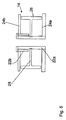
図4の代替形態では、アーバがプレートから独立して制約されないように設計され、軸方向位置決め手段のみを形成する。胴部の回転駆動手段は、胴部の周囲部のところで作用するロールベアリング52である。ロールベアリングは胴部と時計の枠との間の接続部として機能し、橋掛け部を使用することなく香箱を掛止するのを可能にする。また、胴部を確実に枢動させるために外側ランナ(outer runner)を使用することも可能である。 In the alternative of FIG. 4, the arbor is designed such that it is not constrained independently of the plate, forming only the axial positioning means. The rotation driving means of the trunk is a roll bearing 52 that acts at the periphery of the trunk. The roll bearing functions as a connection between the body and the watch frame and allows the barrel to be hooked without using a bridge. It is also possible to use an outer runner to ensure that the barrel is pivoted.
香箱を組み立てるために以下のステップが実行される:
− 下側ハブ22aをアーバ20上に設置するステップ、
− ぜんまい18a及び18bに連関した胴部14をアーバ20上に設置するステップ、
− 下側ぜんまい18aを下側ハブ22aに接続するステップ、
− 上側ハブ22bをアーバ20上に設置するステップ、
− 上側ぜんまい18bを上側ハブ22bに接続するステップ、
− 当事例ではアーバ20内のねじ34を手動で締めることによりなされる、軸方向位置決め手段を位置決めするステップ。
The following steps are performed to assemble the barrel:
-Installing the
-Installing the
-Connecting the
-Installing the
-Connecting the
Positioning the axial positioning means, which in this case is done by manually tightening the
図5の代替的図形では、下側ハブ22aが上側ハブ22bを回転駆動させるのに使用される。有利には、下側ハブ22aが、その端部のところでナット又はステップねじ34を受けることにより軸方向位置決め手段に寄与することができる。下側ハブが、時計に固定されて設置される心棒上で位置決めされ得るチューブを形成する。したがって、香箱は、枢動軸又は回転軸を用いることなく時計から独立して組み立てられ得るような、時計に予め固着される心棒上に後から設置され得る独立機能組立体を形成することができる。
In the alternative graphic of FIG. 5, the
この実施例では、下側ハブがアーバとしても機能する。したがって、以下のステップが実行される:
− 下側ハブ22aを得るステップ、
− ぜんまい18a及び18bに連関した胴部14を下側ハブ22a上に設置するステップ、
− 下側ぜんまい18aを下側ハブ22aに接続するステップ、
− 上側ハブ22bを下側ハブ22a上に設置するステップ、
− 上側ぜんまい18bを上側ハブ22bに接続するステップ、
− 当事例では下側ハブ22a内のねじ34を手動で締めることによりなされる、軸方向位置決め手段を位置決めするステップ。
In this embodiment, the lower hub also functions as an arbor. The following steps are therefore performed:
-Obtaining the
-Installing the
-Connecting the
-Installing the
-Connecting the
Positioning the axial positioning means, in this case by manually tightening the
実際的な視点からでは、その留め部がぜんまいの内側端部と結合するようになるまで各々のハブを回転させることにより、ぜんまいがそれぞれのハブに接続され得ることに留意されたい。 It should be noted that from a practical point of view, the mainspring can be connected to the respective hub by rotating each hub until its catches are mated with the inner end of the mainspring.
したがって、香箱10が下側蓋24aにより巻き機構(winding system)に接続される場合、下側ぜんまい18aが下側ハブ22aを介して装着される。下側ぜんまい18aが胴部14を介して段階的に上側ぜんまい18bの方に移り、それにより上側ぜんまい18bが装着されるようになる。それにより、上側ハブ22bを介して上側蓋24bのところでトルクが得られる。上側蓋を巻き機構に接続し、下側蓋を時方輪列に接続することにより、この構成を逆にすることも可能である。
Therefore, when the
この提案される構成は部品の数が少なく、大きさが縮小されることから、有利には単純な構成となる。2つのぜんまいが互いに独立して設置され得、それにより組み立て作業も容易になる。 This proposed configuration is advantageously a simple configuration due to the small number of parts and reduced size. The two mainsprings can be installed independently of each other, thereby facilitating assembly work.
このように、2つのぜんまい18a、18bを組み込む香箱10が得られ、香箱によって提供されるトルクを増大させるか又はパワー・リザーブを向上させることが可能となる。したがって、例えば、2つの香箱10の上側蓋に噛合される中間車を使用して、上述した2つの香箱10を接続することにより、これらの香箱を直列又は並列に連関することが可能となる。この中間車は、例えば、ムーブメントの中間車(middle wheel)であってよい。
In this way, the
当業者は、使用されるぜんまいを、装着の制限を可能にする自動巻きぜんまいか、又は胴部14と堅固に結合する手動巻きぜんまいのどちらにでも選択することができる。
The person skilled in the art can select the mainspring to be used, either an automatic mainspring that allows for limited mounting or a manual mainspring that is tightly coupled to the
Claims (16)
重ね合わされる第1の分室(16a)及び第2の分室(16b)を画定する胴部(14)と、
第1の蓋(24a)に固定され、第1の分室内に少なくとも部分的に収容される第1の管状ハブ(22a)と、
第2の蓋(24b)に固定され、第2の分室内に少なくとも部分的に収容される第2の管状ハブ(22b)と
を備え、
各々の分室が螺旋状に巻かれるぜんまい(18a、18b)を含有し、前記ぜんまい(18a、18b)の一方の内側端部が前記第1のハブ及び前記第2のハブとそれぞれ結合し、前記ぜんまい(18a、18b)の第2の端部が前記胴部(14)と結合し、
前記分室が前記蓋の側で開いており、前記第1及び第2の蓋が前記胴部(14)に関して制約されず、各々が周囲歯部を備え、前記胴部(14)が歯部を有さない、
時計香箱。 A watch barrel,
A body (14) defining a first compartment (16a) and a second compartment (16b) to be superimposed;
A first tubular hub (22a) fixed to the first lid (24a) and at least partially housed in the first compartment;
A second tubular hub (22b) fixed to the second lid (24b) and at least partially housed in the second compartment;
Each of the compartments contains a spirally wound mainspring (18a, 18b), and one inner end of the mainspring (18a, 18b) is coupled to the first hub and the second hub, respectively, The second end of the mainspring (18a, 18b) is joined to the body (14);
The compartment is open on the side of the lid, the first and second lids are not constrained with respect to the barrel (14), each comprising a peripheral tooth, and the barrel (14) having a tooth Do not have,
Clock barrel.
前記ぜんまい(18b、18a)に連関した前記胴部(14)を前記第1のハブ(22a)上に設置するステップと、
前記下側ぜんまい(18a)を前記第1のハブ(22a)に接続するステップと、
前記第2のハブ(22b)を前記アーバ上に設置するステップと、
前記第2のぜんまい(18b)を前記第2のハブ(22b)に接続するステップと、
前記軸方向位置決め手段を前記アーバ(20)上で位置決めするステップと
を含むことを特徴とする、請求項15に記載の時計を組み立てるための方法。
Installing the lower hub (22a) on the arbor (20);
Installing the body (14) associated with the mainspring (18b, 18a) on the first hub (22a);
Connecting the lower spring (18a) to the first hub (22a);
Installing the second hub (22b) on the arbor;
Connecting the second mainspring (18b) to the second hub (22b);
16. A method for assembling a timepiece according to claim 15, characterized in that it comprises the step of positioning said axial positioning means on said arbor (20).
Applications Claiming Priority (3)
| Application Number | Priority Date | Filing Date | Title |
|---|---|---|---|
| CH00340/12 | 2012-03-09 | ||
| CH00340/12A CH706214B1 (en) | 2012-03-09 | 2012-03-09 | Barrel timepiece. |
| PCT/EP2013/054765 WO2013132076A1 (en) | 2012-03-09 | 2013-03-08 | Barrel |
Publications (3)
| Publication Number | Publication Date |
|---|---|
| JP2015509600A JP2015509600A (en) | 2015-03-30 |
| JP2015509600A5 JP2015509600A5 (en) | 2016-04-28 |
| JP6072837B2 true JP6072837B2 (en) | 2017-02-01 |
Family
ID=47901045
Family Applications (1)
| Application Number | Title | Priority Date | Filing Date |
|---|---|---|---|
| JP2014560400A Expired - Fee Related JP6072837B2 (en) | 2012-03-09 | 2013-03-08 | Barrel |
Country Status (7)
| Country | Link |
|---|---|
| US (1) | US9335738B2 (en) |
| EP (1) | EP2823364B1 (en) |
| JP (1) | JP6072837B2 (en) |
| CN (1) | CN104220939B (en) |
| CH (1) | CH706214B1 (en) |
| HK (1) | HK1204100A1 (en) |
| WO (1) | WO2013132076A1 (en) |
Cited By (1)
| Publication number | Priority date | Publication date | Assignee | Title |
|---|---|---|---|---|
| US8754204B2 (en) | 2007-11-20 | 2014-06-17 | Olympus Corporation | Method for preparing stool sample, solution for preparing stool sample, and kit for collecting stool |
Families Citing this family (9)
| Publication number | Priority date | Publication date | Assignee | Title |
|---|---|---|---|---|
| CN108196438B (en) * | 2012-04-04 | 2020-09-08 | 劳力士有限公司 | Shaft, spring, barrel including shaft and spring, timepiece movement, wristwatch and watch |
| EP2887150A1 (en) * | 2013-12-20 | 2015-06-24 | ETA SA Manufacture Horlogère Suisse | Optimised timepiece barrel |
| EP2952979B1 (en) * | 2014-06-03 | 2017-03-01 | Nivarox-FAR S.A. | Timepiece component made of photostructurable glass |
| EP3208666B1 (en) * | 2016-02-19 | 2018-11-21 | Blancpain SA | Clock wheel with backlash compensation |
| CH712308A1 (en) * | 2016-03-30 | 2017-10-13 | Officine Panerai Ag | Self lubricated cylinder system for timepiece. |
| CN107817670A (en) * | 2016-09-13 | 2018-03-20 | 天津海鸥表业集团有限公司 | Double-spring watch driving assembly |
| DE102016122936B4 (en) * | 2016-11-28 | 2018-11-08 | Lange Uhren Gmbh | Barrel for a watch |
| EP3654109B1 (en) * | 2018-11-13 | 2021-03-31 | Patek Philippe SA Genève | Timepiece comprising two energy sources |
| CN109579662A (en) * | 2019-01-28 | 2019-04-05 | 汉中万目仪电有限责任公司 | Bottom of a cup rule |
Family Cites Families (20)
| Publication number | Priority date | Publication date | Assignee | Title |
|---|---|---|---|---|
| US410327A (en) * | 1889-09-03 | meylan | ||
| US249845A (en) * | 1881-11-22 | Strike-spring for eight-day clocks | ||
| BE567865A (en) * | ||||
| GB103121A (en) * | 1915-12-31 | 1918-05-02 | Wuthrich Edouard | |
| CH90009A (en) * | 1917-10-18 | 1921-07-16 | Victor Talking Machine Co | Multiple spring motor. |
| GB147339A (en) * | 1919-12-16 | 1920-07-22 | Thomas Frederick Redington | Improvements in spring-driven mechanism |
| US1796374A (en) * | 1930-02-13 | 1931-03-17 | Albert F Kendle | Mainspring barrel |
| CH599580B5 (en) * | 1974-08-22 | 1978-05-31 | Longines Montres Comp D | |
| JPS5194389U (en) * | 1975-01-28 | 1976-07-29 | ||
| IT1074807B (en) * | 1976-02-18 | 1985-04-20 | Bouchet Lassale Sa | WATERPROOFING DEVICE FOR CLOCK BARREL |
| ATE390651T1 (en) * | 2000-01-06 | 2008-04-15 | Chopard Manufacture Sa | DRIVE DEVICE FOR CLOCK MOVEMENT WITH LARGE POWER RESERVE |
| DE10357228A1 (en) * | 2003-12-08 | 2005-07-07 | Lange Uhren Gmbh | Barrel device |
| EP1582943B1 (en) * | 2004-04-01 | 2008-09-03 | Richemont International S.A. | Watch movement comprising several barrels |
| CN201116972Y (en) * | 2007-08-28 | 2008-09-17 | 天津海鸥表业集团有限公司 | Watch tandem type original power mechanism |
| EP2060957A1 (en) * | 2007-11-16 | 2009-05-20 | ETA SA Manufacture Horlogère Suisse | Motor element with springs for timepiece movement |
| CN201181396Y (en) * | 2008-03-31 | 2009-01-14 | 天津海鸥表业集团有限公司 | Coaxial double-layer barrel link gear of watch |
| CH699988A2 (en) * | 2008-11-28 | 2010-05-31 | Patek Philippe Sa Geneve | Driving member for watch movement. |
| CH702856A2 (en) * | 2010-03-22 | 2011-09-30 | Patek Philippe Sa Geneve | Watch movement. |
| CH704249B1 (en) * | 2010-12-20 | 2015-02-27 | Elsbeth Roesner | Driving member for watch movement. |
| CH706641A2 (en) * | 2012-06-22 | 2013-12-31 | Cartier Creation Studio Sa | Body engine for clockwork. |
-
2012
- 2012-03-09 CH CH00340/12A patent/CH706214B1/en unknown
-
2013
- 2013-03-08 WO PCT/EP2013/054765 patent/WO2013132076A1/en active Application Filing
- 2013-03-08 CN CN201380012942.5A patent/CN104220939B/en not_active Expired - Fee Related
- 2013-03-08 JP JP2014560400A patent/JP6072837B2/en not_active Expired - Fee Related
- 2013-03-08 EP EP13710338.8A patent/EP2823364B1/en not_active Not-in-force
- 2013-03-08 US US14/383,635 patent/US9335738B2/en active Active
-
2015
- 2015-05-06 HK HK15104318.0A patent/HK1204100A1/en not_active IP Right Cessation
Cited By (1)
| Publication number | Priority date | Publication date | Assignee | Title |
|---|---|---|---|---|
| US8754204B2 (en) | 2007-11-20 | 2014-06-17 | Olympus Corporation | Method for preparing stool sample, solution for preparing stool sample, and kit for collecting stool |
Also Published As
| Publication number | Publication date |
|---|---|
| US20150138932A1 (en) | 2015-05-21 |
| CN104220939A (en) | 2014-12-17 |
| JP2015509600A (en) | 2015-03-30 |
| US9335738B2 (en) | 2016-05-10 |
| HK1204100A1 (en) | 2015-11-06 |
| EP2823364B1 (en) | 2016-05-25 |
| WO2013132076A1 (en) | 2013-09-12 |
| EP2823364A1 (en) | 2015-01-14 |
| CN104220939B (en) | 2016-10-12 |
| CH706214B1 (en) | 2016-09-30 |
| CH706214A1 (en) | 2013-09-13 |
Similar Documents
| Publication | Publication Date | Title |
|---|---|---|
| JP6072837B2 (en) | Barrel | |
| US8430559B2 (en) | Driving member for a timepiece movement | |
| JP4499681B2 (en) | A portable watch including at least two adjustment systems | |
| US8379493B2 (en) | Spring loaded driving member for timepiece movement | |
| JP5999882B2 (en) | clock | |
| US8702301B2 (en) | Timepiece bearing, movement, and portable timepiece | |
| JP2000321370A5 (en) | ||
| JP5118142B2 (en) | Timepiece | |
| JP2015509600A5 (en) | ||
| JP6042534B2 (en) | Driving member for watch movement | |
| EP3002636A1 (en) | Disengaging coaxial wheels of a watch movement | |
| JP2019215259A (en) | Barrel assembly, movement and watch | |
| US8807828B2 (en) | Timepiece | |
| JP5918448B2 (en) | Timer barrel | |
| JP5960923B2 (en) | Timer barrel | |
| WO2013104941A1 (en) | Timepiece with automatic winding | |
| JP2002365377A (en) | Drive mechanism and clock | |
| JP6180296B2 (en) | Pipe index wheel and time difference correction mechanism | |
| EP2550565B1 (en) | Clockwork | |
| JP2016512596A5 (en) | ||
| JP6591883B2 (en) | Constant force spring adjustment mechanism, constant force device, and mechanical watch | |
| JP2013145212A (en) | Power generation device for clock, incense box using the same and clock | |
| CN113189855A (en) | Gear train mechanism, movement and clock | |
| CN113176721A (en) | Clock and watch | |
| JP2019105606A (en) | Barrel, timepiece movement and timepiece |
Legal Events
| Date | Code | Title | Description |
|---|---|---|---|
| A521 | Request for written amendment filed |
Free format text: JAPANESE INTERMEDIATE CODE: A523 Effective date: 20160308 |
|
| A621 | Written request for application examination |
Free format text: JAPANESE INTERMEDIATE CODE: A621 Effective date: 20160308 |
|
| TRDD | Decision of grant or rejection written | ||
| A01 | Written decision to grant a patent or to grant a registration (utility model) |
Free format text: JAPANESE INTERMEDIATE CODE: A01 Effective date: 20161206 |
|
| A61 | First payment of annual fees (during grant procedure) |
Free format text: JAPANESE INTERMEDIATE CODE: A61 Effective date: 20161228 |
|
| R150 | Certificate of patent or registration of utility model |
Ref document number: 6072837 Country of ref document: JP Free format text: JAPANESE INTERMEDIATE CODE: R150 |
|
| LAPS | Cancellation because of no payment of annual fees |