JP6072825B2 - Use of gradient coils to correct higher order BO field inhomogeneities in MR imaging - Google Patents
Use of gradient coils to correct higher order BO field inhomogeneities in MR imaging Download PDFInfo
- Publication number
- JP6072825B2 JP6072825B2 JP2014548272A JP2014548272A JP6072825B2 JP 6072825 B2 JP6072825 B2 JP 6072825B2 JP 2014548272 A JP2014548272 A JP 2014548272A JP 2014548272 A JP2014548272 A JP 2014548272A JP 6072825 B2 JP6072825 B2 JP 6072825B2
- Authority
- JP
- Japan
- Prior art keywords
- coil
- gradient
- magnetic field
- current
- coil section
- Prior art date
- Legal status (The legal status is an assumption and is not a legal conclusion. Google has not performed a legal analysis and makes no representation as to the accuracy of the status listed.)
- Expired - Fee Related
Links
Images


Classifications
-
- G—PHYSICS
- G01—MEASURING; TESTING
- G01R—MEASURING ELECTRIC VARIABLES; MEASURING MAGNETIC VARIABLES
- G01R33/00—Arrangements or instruments for measuring magnetic variables
- G01R33/20—Arrangements or instruments for measuring magnetic variables involving magnetic resonance
- G01R33/28—Details of apparatus provided for in groups G01R33/44 - G01R33/64
- G01R33/38—Systems for generation, homogenisation or stabilisation of the main or gradient magnetic field
- G01R33/387—Compensation of inhomogeneities
- G01R33/3875—Compensation of inhomogeneities using correction coil assemblies, e.g. active shimming
-
- G—PHYSICS
- G01—MEASURING; TESTING
- G01R—MEASURING ELECTRIC VARIABLES; MEASURING MAGNETIC VARIABLES
- G01R33/00—Arrangements or instruments for measuring magnetic variables
- G01R33/20—Arrangements or instruments for measuring magnetic variables involving magnetic resonance
- G01R33/28—Details of apparatus provided for in groups G01R33/44 - G01R33/64
- G01R33/38—Systems for generation, homogenisation or stabilisation of the main or gradient magnetic field
- G01R33/385—Systems for generation, homogenisation or stabilisation of the main or gradient magnetic field using gradient magnetic field coils
Description
本発明は、磁気共鳴(MR:magnetic resonance)画像法及び磁気共鳴スペクトロスコピーの分野に関する。本発明は、MR装置の検査ボリューム内のほぼ均一な主磁場B0の磁場の不均一性を補正する方法に関する。本発明は、MR装置、及びMR装置上で実行されるコンピュータプログラムにも関する。 The present invention relates to the fields of magnetic resonance (MR) imaging and magnetic resonance spectroscopy. The present invention relates to a method for correcting magnetic field inhomogeneities of a substantially uniform main magnetic field B 0 in the examination volume of an MR apparatus. The present invention also relates to an MR apparatus and a computer program executed on the MR apparatus.
二次元画像又は三次元画像を形成するために、磁場と核スピンとの間の相互作用を利用する画像形成MR法がとりわけ医療診断分野で今日広く使われており、その理由は、軟組織の画像化ではそれらの方法が多くの点で他の画像法よりも優れており、電離放射線を必要とせず、通常非侵襲的だからである。 Imaging MR methods that utilize the interaction between magnetic fields and nuclear spins to form two-dimensional or three-dimensional images are widely used today, particularly in the field of medical diagnostics, because of soft tissue images This is because they are superior to other imaging methods in many respects, do not require ionizing radiation, and are usually non-invasive.
一般的なMR法によれば、検査される患者の身体が強い均一磁場B0の中に配置され、その磁場の向きは同時に、測定を基づかせる座標系の軸(通常z軸)を規定する。磁場B0は、磁場強度に応じて個々の核スピンについて様々なエネルギ準位をもたらし、その核スピンは、既定の周波数(所謂ラーモア周波数又はMR周波数)の電磁交番磁場(RF場)を印加することによって励起され得る(スピン共鳴)。巨視的な観点から、個々の核スピンの分布は、適切な周波数の電磁パルス(RFパルス)の印加により平衡状態から偏向され得る全体的な磁化をもたらす一方、磁場B0は、磁化がz軸の周りで歳差運動を実行するようにz軸に対して垂直に延在する。この歳差運動は、その開口角度がフリップ角と呼ばれるコーンの表面を表す。フリップ角の大きさは、印加電磁パルスの強度及び持続時間に依存する。所謂90°パルスの場合、スピンはz軸から横断方向平面(フリップ角90°)まで偏向される。 According to a typical MR method, the patient's body to be examined is placed in a strong uniform magnetic field B 0 , the direction of which simultaneously defines the axis of the coordinate system on which the measurement is based (usually the z-axis). . The magnetic field B 0 provides various energy levels for individual nuclear spins depending on the magnetic field strength, and the nuclear spins apply an electromagnetic alternating magnetic field (RF field) of a predetermined frequency (so-called Larmor frequency or MR frequency). Can be excited (spin resonance). From a macroscopic point of view, the distribution of individual nuclear spins results in an overall magnetization that can be deflected from equilibrium by the application of an electromagnetic pulse of appropriate frequency (RF pulse), while the magnetic field B 0 has a magnetization that is z-axis. Extends perpendicular to the z-axis to perform precession around. This precession represents the surface of the cone whose opening angle is called the flip angle. The magnitude of the flip angle depends on the intensity and duration of the applied electromagnetic pulse. In the case of a so-called 90 ° pulse, the spin is deflected from the z-axis to the transverse plane (flip angle 90 °).
RFパルスの停止後、磁化は、最初の平衡状態へと緩和する。ここでz方向における磁化が、第1の時間定数T1(スピン格子又は長手方向緩和時間)で再び構築され、z方向に垂直な方向の磁化が第2の時間定数T2(スピンスピン又は横断方向緩和時間)で緩和する。磁化の変動は、磁化の変動がz軸に対して垂直な方向で測定されるようにMR装置の検査ボリューム内で配置され、方向付けられる受信RFコイルによって検出され得る。横断方向の磁化の減衰は、例えば90°パルスの印可後、同じ位相にある規則正しい状態から全ての位相角が一様に分散される(ディフェージング)状態への(局所磁場不均一性によりもたらされる)核スピンの移行を伴う。ディフェージングは、再フォーカスパルス(例えば180°パルス)によって補償され得る。これは、受信コイルにおいてエコー信号(スピンエコー)を生み出す。 After the RF pulse stops, the magnetization relaxes to the initial equilibrium state. Here the magnetization in the z direction is reconstructed with a first time constant T 1 (spin lattice or longitudinal relaxation time) and the magnetization in the direction perpendicular to the z direction is a second time constant T 2 (spin spin or transverse (Direction relaxation time). The magnetization variation can be detected by a receive RF coil that is placed and oriented in the examination volume of the MR device such that the magnetization variation is measured in a direction perpendicular to the z-axis. Transverse magnetization decay is caused by local magnetic field inhomogeneity, for example from a regular state in the same phase after application of a 90 ° pulse, to a state where all phase angles are uniformly distributed (dephasing) ) With nuclear spin transfer. Dephasing can be compensated by a refocus pulse (eg, a 180 ° pulse). This produces an echo signal (spin echo) in the receiving coil.
体における空間分解能を実現するために、3つの主軸に沿って延在する線形傾斜磁場が一様な磁場B0上に重畳され、スピン共鳴周波数の線形空間依存性をもたらす。次いで、受信コイルにおいて拾われる信号が、体の様々な位置に関連付けられ得る様々な周波数の成分を含む。受信コイルによって得られる信号データは空間周波数領域に対応し、k空間データと呼ばれる。k空間データは通常、様々な位相エンコードで取得される複数のラインを含む。各ラインは、幾つかのサンプルを集めることによってデジタル化される。フーリエ変換により、1組のk空間データがMR画像に変換される。 In order to achieve spatial resolution in the body, a linear gradient magnetic field extending along the three principal axes is superimposed on the uniform magnetic field B 0 , resulting in a linear spatial dependence of the spin resonance frequency. The signal picked up in the receive coil then contains components of different frequencies that can be associated with different positions of the body. The signal data obtained by the receiving coil corresponds to the spatial frequency domain and is called k-space data. k-space data typically includes multiple lines acquired with various phase encodings. Each line is digitized by collecting several samples. A set of k-space data is converted into an MR image by Fourier transform.
MR画像法では、主磁場B0の均一性が極めて重要な要素である。固定シム手段(stationary shim measures)(例えば検査ボリューム内又は付近の適切な位置に適用される強磁性体)と組み合わせて主磁石を適切に設計することに基づき、使用されるMR装置の検査ボリューム内で所要の磁場の均一性が実現される。更に、シミングコイルに適切な電流を流すことにより、主磁場のシミングを更に改善する1組の(一次、二次、及び該当する場合は三次)シムコイルがMR撮像セッション中に活性化される。 In MR imaging, the uniformity of the main magnetic field B 0 is a critical factor. In the inspection volume of the MR device used, based on the proper design of the main magnet in combination with stationary shim measures (eg ferromagnetic material applied at or near the appropriate position in the inspection volume) The required magnetic field uniformity is achieved. In addition, a set of (primary, secondary, and tertiary if applicable) shim coils are activated during the MR imaging session that further improves the main magnetic field shimming by passing the appropriate current through the shimming coils.
今日臨床に用いられているMR装置では、1組の5個のシムコイルを含む高次のシムシステムが概して存在する。かかるシムシステムは、個々のシムコイルに適切な電流を流すための1組の5個の増幅器と、MR装置のバックエンド制御電子機器へのインターフェイスとを含む。かかるシステムの欠点は、その複雑さと費用の高さである。 In MR devices in clinical use today, there is generally a higher order shim system that includes a set of five shim coils. Such a shim system includes a set of five amplifiers for passing the appropriate current through the individual shim coils and an interface to the back-end control electronics of the MR device. The drawback of such a system is its complexity and high cost.
上記の内容から、改善されたMR技法の需要があることが容易に理解される。従って本発明の目的は、主磁場B0の高次の場の不均一性を効果的に補正できるようにする方法を提供することである。 From the above, it can be readily appreciated that there is a need for improved MR techniques. Accordingly, an object of the present invention is to provide a way to effectively correct the non-uniformity of high-order field of the main magnetic field B 0.
本発明によれば、MR装置の検査ボリューム内のほぼ均一な主磁場B0の磁場の不均一性を補正する方法が開示される。本発明は、主磁場B0上に重畳される少なくとも1つの傾斜磁場コイルの磁場により主磁場B0の高次の場の不均一性が補償されるように、複数の傾斜磁場コイルのうちの少なくとも1つの傾斜磁場コイルの2つ以上のコイルセクションを通る電流が制御されることを提案する。 In accordance with the present invention, a method for correcting magnetic field inhomogeneities of a substantially uniform main magnetic field B 0 within an examination volume of an MR apparatus is disclosed. The present invention, by a magnetic field of at least one gradient coil is superimposed on the main magnetic field B 0 of the higher order field of the main magnetic field B 0 as inhomogeneities are compensated, of the plurality of gradient coils It is proposed that the current through two or more coil sections of at least one gradient coil is controlled.
高次の空間磁場分布を発生させて主磁場B0をシミングするために、MR装置の傾斜磁場コイルシステムを使用することが本発明の要点である。 The main magnetic field B 0 by generating a spatial magnetic field distribution of higher order to shimming, it is the main point of the present invention using a gradient coil system of an MR apparatus.
本発明によれば、MR装置のシムシステムの典型的には5チャネルのうち、最大3つを省略することができ、その理由は主磁場B0の対応する高次の場の不均一性が、MR装置内に存在する3つの傾斜磁場コイル(x傾斜、y傾斜、及びz傾斜)によってどのみち補償され得るからである。従って、MR装置のシムシステムの費用を著しく下げることができる。 According to the present invention, among the typically 5 channels shim system of the MR device, it is possible to omit the up to three, non-uniformity of the high-order field because the corresponding main magnetic field B 0 is This is because any of the three gradient coils (x gradient, y gradient, and z gradient) existing in the MR apparatus can be compensated. Therefore, the cost of the MR system shim system can be significantly reduced.
本発明の見識は、(それ自体は知られている)区分された傾斜磁場コイルが使用されるとき、傾斜磁場コイルによって高次の磁場分布が発生させられ得ることである。指定されたB0の均一性を実現するために、MR装置の個々の傾斜磁場コイルの異なるコイルセクションを通る電流が互いに独立に制御される必要がある。主磁場B0の高次のシミングのために本発明の方法が適用されるとき、概して傾斜磁場コイルのうちの1つの1つのコイルセクションを流れる電流は、同じ傾斜磁場コイルの別のコイルセクションを流れる電流と異なる。 The insight of the present invention is that a higher order magnetic field distribution can be generated by a gradient coil when a segmented gradient coil (known per se) is used. In order to achieve the specified B 0 uniformity, the currents through the different coil sections of the individual gradient coils of the MR device need to be controlled independently of each other. When the method of the present invention is applied for higher order shimming of the main magnetic field B 0, the current flowing through one coil section of one of the gradient coils generally passes another coil section of the same gradient coil. Different from the flowing current.
好ましい実施形態では、本発明の方法が、
− RFパルス及び切り替えられた傾斜磁場を含む撮像シーケンスに患者の身体の一部をかけるステップと、
− 撮像信号データを取得するステップと、
− 撮像信号データからMR画像を再構築するステップと
を含み、主磁場B0の高次の場の不均一性が撮像シーケンス中に及び/又は撮像信号データの取得中に補正されるように、傾斜磁場コイルのコイルセクションを通る電流が制御される。
In a preferred embodiment, the method of the invention comprises
Applying a part of the patient's body to an imaging sequence comprising an RF pulse and a switched gradient field;
-Acquiring imaging signal data;
Reconstructing the MR image from the imaging signal data, so that higher-order field inhomogeneities of the main magnetic field B 0 are corrected during the imaging sequence and / or during acquisition of the imaging signal data, The current through the coil section of the gradient coil is controlled.
本発明のシミング手法は、磁気共鳴の励起中に、並びにMR画像がそこから最終的に再構築されるMR撮像信号データの取得中に適用され得る。傾斜磁場コイルの様々なセクションに流される電流が個々に、例えば主磁場の特殊な擾乱を発生させる被検査身体の形状に応じて制御され得るので、本発明の方法は動的なシミングを可能にする。個々に異なる患者の身体の形状によって発生される主要な場の擾乱が、本発明による傾斜磁場コイルによって発生される高次の磁場分布によって補償され得ることが実際には判明する。 The shimming technique of the present invention can be applied during magnetic resonance excitation as well as acquisition of MR imaging signal data from which MR images are finally reconstructed. The method of the present invention allows dynamic shimming because the currents flowing in the various sections of the gradient coil can be controlled individually, for example, depending on the shape of the body under test that generates a special disturbance in the main magnetic field. To do. It turns out that the main field disturbances generated by the individual patient body shapes can be compensated by the higher-order magnetic field distribution generated by the gradient coils according to the invention.
実際に画像を取得する前のキャリブレーションスキャンにより、主磁場分布を測定することが可能である。本発明によれば、その後、画像を取得する間の最適な主磁場の均一性を実現するために、取得されるキャリブレーション信号データに基づき、傾斜磁場コイルの個々のコイルセクションに流される電流が制御され得る。検査ボリューム内のB0分布を測定する技法は当技術分野でそれ自体は知られている。本発明によるB0シミングのために傾斜磁場コイルセクションに流される電流を決定するために、かかる既知の技法が使用され得る。 The main magnetic field distribution can be measured by a calibration scan before actually acquiring an image. In accordance with the present invention, the currents passed through the individual coil sections of the gradient coil are then based on the acquired calibration signal data to achieve optimal main field uniformity during image acquisition. Can be controlled. Techniques for measuring the B 0 distribution within the examination volume are known per se in the art. Such known techniques can be used to determine the current passed through the gradient coil section for B 0 shimming according to the present invention.
これまでに説明した本発明の方法は、検査ボリューム内でほぼ均一な定常磁場B0を発生させるための少なくとも1つの主磁石コイルと、検査ボリューム内の様々な空間方向に切り替えられた傾斜磁場を発生させるための幾つかの傾斜磁場コイルであって、各傾斜磁場コイルは2つ以上のコイルセクションを含む、幾つかの傾斜磁場コイルと、検査ボリューム内でRFパルスを発生させ、且つ/又は検査ボリューム内に配置される患者の身体からMR信号を受信するための少なくとも1つのRFコイルと、RFパルス及び切り替えられる傾斜磁場の時間的連続性を制御するための制御ユニットとを含むMR装置によって実行され得る。本発明によれば、各傾斜磁場コイルのコイルセクションを流れる電流を互いに独立に制御することができる。 The method of the present invention described so far comprises at least one main magnet coil for generating a substantially uniform stationary magnetic field B 0 in the examination volume and a gradient magnetic field switched in various spatial directions in the examination volume. A number of gradient coils for generating, each gradient coil including two or more coil sections, and generating gradient and / or inspection of RF pulses in the examination volume; Performed by an MR apparatus comprising at least one RF coil for receiving MR signals from a patient's body disposed within the volume and a control unit for controlling the temporal continuity of the RF pulses and the switched gradient field Can be done. According to the present invention, the currents flowing through the coil sections of each gradient coil can be controlled independently of each other.
MR装置を制御するコンピュータプログラムであって、上記で説明した本発明の方法を実行する、コンピュータプログラムが利用され得る。そのコンピュータプログラムはデータ記憶媒体上にあっても、ダウンロードしてMR装置の制御ユニット内にインストールするためにデータネットワーク内にあっても良い。 A computer program for controlling the MR apparatus, which executes the method of the present invention described above, can be used. The computer program may be on a data storage medium or in a data network for downloading and installing in the control unit of the MR device.
添付図面は本発明の好ましい実施形態を開示する。但し、これらの図面は本発明の限界を定義するものではなく、例示目的で考案されているに過ぎないことが理解されるべきである。 The accompanying drawings disclose preferred embodiments of the present invention. It should be understood, however, that these drawings are not intended to define the limits of the present invention, but are designed for illustrative purposes only.
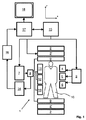
図1を参照すると、MR装置1が示されている。この装置は、ほぼ均一な時間的に一定の主磁場B0が検査ボリュームを通りz軸に沿って作り出されるように、超伝導又は常伝導主磁石コイル2を含む。この装置は、1組の(一次、並びに該当する場合は二次、及び三次)シミングコイル2’を更に含み、検査ボリューム内のB0の偏向を最小限にするために、組2’の個々のシムコイルを通る電流の流れが制御可能である。
Referring to FIG. 1, an MR apparatus 1 is shown. The apparatus includes a superconducting or normal conducting
磁気共鳴発生及び操作システムは、MR撮像を行うために、一連のRFパルス及び切り替えられた傾斜磁場を印加して、核磁気スピンを反転させ又は励起し、磁気共鳴を引き起こし、磁気共鳴を再フォーカスし、磁気共鳴を操作し、磁気共鳴を空間的に及び他の方法でエンコードし、スピンを飽和させるなどする。 The magnetic resonance generation and manipulation system applies a series of RF pulses and a switched gradient magnetic field to invert or excite nuclear magnetic spins, cause magnetic resonance, and refocus magnetic resonance for MR imaging. Manipulating the magnetic resonance, encoding the magnetic resonance spatially and in other ways, saturating the spin, etc.
最も詳細には、勾配パルス増幅器3が、検査ボリュームのx軸、y軸、及びz軸に沿い、全身勾配コイル4、5、及び6のうちの選択されたコイルに電流パルスを加える。検査ボリューム内にRFパルスを伝送するために、デジタルRF周波送信機7が送受信スイッチ8を介してRFパルス又はパルスパケットを身体RFコイル9に伝送する。典型的なMR撮像シーケンスは、短い持続時間のRFパルスセグメントのパケットから成り、これらが互いに、及び加えられる任意の傾斜磁場とともにとられることにより、核磁気共鳴の選択された操作を実現する。RFパルスは、飽和させ、共鳴を励起し、磁化を反転させ、共鳴を再フォーカスし、又は共鳴を操作するために使用され、検査ボリューム内に配置される身体10の一部分を選択するために使用される。MR信号は、身体RFコイル9によっても拾われる。
Most particularly, the
パラレルイメージングにより身体10の限られた領域のMR画像を生成するために、1組の局所アレイRFコイル11、12、13が撮像のために選択された領域に隣接して配置される。アレイコイル11、12、13は、身体コイルのRF伝送によって引き起こされるMR信号を受信するために使用され得る。
In order to generate an MR image of a limited area of the
結果として生じるMR信号が身体RFコイル9及び/又はアレイRFコイル11、12、13によって拾われ、好ましくは前置増幅器(不図示)を含む受信機14によって復調される。受信機14は、送受信スイッチ8を介してRFコイル9、11、12に接続される。
The resulting MR signal is picked up by the
ホストコンピュータ15はシミングコイル2’、勾配パルス増幅器3、及び送信機7を制御し、エコープラナー撮像(EPI:echo planar imaging)、エコーボリューム撮像、勾配及びスピンエコー撮像、高速スピンエコー撮像など、複数のMR撮像シーケンスの何れかを発生させる。選択されたシーケンスについて、受信機14が各RF励起パルスの後に単一の又は複数のMRデータラインを立て続けに受信する。データ取得システム16が受信信号のアナログ/デジタル変換を行い、各MRデータラインを更なる処理に適したデジタル形式に変換する。現代のMR装置では、データ取得システム16が生画像データの取得に特化した別個のコンピュータである。
The
最終的に、フーリエ変換又はSENSEやSMASHなどの他の適切な再構築アルゴリズムを適用する再構築プロセッサ17により、デジタル生画像データが画像表現へと再構築される。MR画像は、患者を通る平面スライス、パラレル平面スライスのアレイ、三次元ボリューム等を表すことができる。その後、画像が画像メモリ内に記憶され、画像メモリでは、スライス、プロジェクション、又は画像表現の他の部分を視覚化のための適切な形式に変換するために画像がアクセスされても良く、視覚化は、例えば結果として生じるMR画像の人間可読表示を提供するビデオモニタ18による。
Finally, the digital raw image data is reconstructed into an image representation by a
本発明の第1の実用的実施形態が、図2を参照して以下の通り説明される。 A first practical embodiment of the invention is described as follows with reference to FIG.
図2は、MR装置1の勾配パルス増幅器3及び傾斜磁場コイル4(の一部)をより詳細に示す。傾斜磁場コイル4は区分され、つまりX方向の傾斜磁場を発生させるために2つのコイルセクションX1及びX2がある。対応する傾斜磁場コイルの半分Y1、Y2、Z1、及びZ2が傾斜磁場コイル5及び6それぞれの中にある。コイルセクションX1及びX2を通る電流が、増幅器(電流源)20及び21によって流される。各増幅器20、21が、1つのコイル半分X1、X2に接続される。図2に示す傾斜磁場コイル4の設計は、今日臨床に用いられている多くのMR装置で実現されている。しかしながら、既知のMR装置では、セクションX1及びX2を駆動する増幅器20、21が、傾斜軸X、Y、Zごとの単一波形発生器に基づき同時に駆動される。対照的に図2では、各増幅器20、21が個々の波形発生器22、23のそれぞれによって駆動される。静的な高次の場の分布のみ発生させる必要がある場合、第2の波形発生器23が、制御可能なDC電流オフセットに単純化され得る。このことは、傾斜磁場コイル4のコイルセクションX1及びX2を流れる電流を本発明に従って互いに独立に制御できるようにする。高次の空間磁場分布は、図2に示すような傾斜磁場コイル4によって発生させることができる。傾斜磁場コイル4の磁場は、MR装置1の検査ボリューム内の主磁場B0上に重畳される。波形発生器22、23を用いてコイルセクションX1及びX2を流れる電流を適切に制御することにより、主磁場B0の高次のシミングが実現される。例えば撮像シーケンス中に、傾斜磁場が発生するように電流がコイルセクションX1及びX2を流れている場合、線形傾斜磁場と一定量の高次(主に三次)の場の成分とが生成される。コイルセクションX1、X2の一方において電流を反転させることにより、B0場(即ち線形傾斜磁場なしの)と、高次(主に二次)の場の分布とが傾斜磁場コイルによって生成される。傾斜磁場コイルによって生成されるこの高次の空間的な場の分布が、上記で説明したように、主磁場B0の対応する高次の場の不均一性を補償するために標的を絞った方法で使用され得る。
FIG. 2 shows in more detail the
上記の技法は、残りの2つの傾斜磁場コイル5及び6にも適用することができる。適切な方法で区分された傾斜磁場コイル4、5、6を使用することにより(コイルセクションは概して検査ボリュームの対称面に対して非対称に配置される)、MR装置1の傾斜システムが検査ボリューム内の磁場分布のz2、x2、及びy2の項(term)を作り出すことができる。これは、従来のシムシステムのルジャンドル係数C20、C21、及びS21に対応する。
The above technique can also be applied to the remaining two
本発明の代わりの実用的実施形態が、図3に示されている。図3では、コイル半分X1及びX2が、内部コイルセクション31、32、並びに外部コイルセクション33及び34のそれぞれに更に分けられる。外部コイルセクション33、34は、内部コイルセクション31、32によって生成される磁場を遮蔽するために使用される。コイルセクション31及び33は、コイルセクション32及び34と同様に直列接続される。外部コイルセクション33、34は、外部コイルセクション33、34を流れる電流を制御する個々の電流源35、36に接続される。電流源35、36の電流は、増幅器37によって生成される電流に重畳される。電流源35、36を適切に制御することにより、傾斜磁場コイル4によって生成される高次の場のパターンがもたらされ、この場のパターンは、主磁場B0のシミングのために本発明に従って使用され得る。図3に示す実施形態では、(傾斜切替中に)増幅器37によって生成される交番電流から独立した外部コイルセクション33、34を通る一定のオフセットとしてDC電流を駆動するために、増幅器35、36が使用され得る。図3の実施形態では、単一の波形発生器38のみが必要である。
An alternative practical embodiment of the present invention is shown in FIG. In Figure 3, the coil half X 1 and X 2, the inner coil section 31, and further divided into respective
図3に示されているように、本発明によれば、コイルセクションX1、X2、31、32、33、34の1つ又は複数が、傾斜磁場コイル4の別のコイルセクションを流れる電流とは独立に個々のコイルセクションを流れる電流を制御する、(DC駆動)電流源に接続されることが概して可能である。対応する電流源によって生成される電流は、例えば動的シミングのために個別に制御され得る。
As shown in FIG. 3, according to the present invention, one or more of the coil sections X 1 , X 2 , 31, 32, 33, 34 flows through another coil section of the
Claims (3)
前記コイルセクションの各々は、直列回路とされる内部コイルセクションと外部コイルセクションとに更に分けられ、
前記MR装置は、
波形発生器の出力部が増幅器の入力部に接続され、当該増幅器の出力部が、前記内部コイルセクションに電流を流すために、前記内部コイルセクションに結合される、波形発生器及び増幅器と、
対応する前記コイルセクションの前記外部セクションを流れる電流を制御するために、対応する前記外部コイルセクションに結合される、個々の電流源と、
を含むことを特徴とする、MR装置。 At least one main magnet coil for generating a substantially uniform stationary magnetic field B 0 in the examination volume and several gradient coils for generating gradient fields switched in various spatial directions in the examination volume Wherein each gradient coil includes two or more coil sections, and several gradient coils and a patient that generates RF pulses in the examination volume and / or is located in the examination volume. The coil section of each gradient coil comprising at least one body RF coil for receiving MR signals from the body and a control unit for controlling the temporal continuity of the RF pulse and the switched gradient magnetic field current through a controllable independently of one another, substantially uniform magnetic main field B 0 in the examination volume of the MR device A MR device having a function of correcting the non-uniformity of,
Each of the coil sections is further divided into an internal coil section and an external coil section that are connected in series,
The MR apparatus comprises:
A waveform generator and an amplifier, wherein an output of the waveform generator is connected to an input of the amplifier, and the output of the amplifier is coupled to the internal coil section for passing current through the internal coil section;
An individual current source coupled to the corresponding outer coil section to control the current flowing through the outer section of the corresponding coil section;
MR apparatus characterized by including .
Applications Claiming Priority (3)
| Application Number | Priority Date | Filing Date | Title |
|---|---|---|---|
| US201161579739P | 2011-12-23 | 2011-12-23 | |
| US61/579,739 | 2011-12-23 | ||
| PCT/IB2012/057166 WO2013093710A1 (en) | 2011-12-23 | 2012-12-11 | Use of gradient coils for correcting higher order bo field inhomogeneities in mr imaging |
Publications (3)
| Publication Number | Publication Date |
|---|---|
| JP2015500725A JP2015500725A (en) | 2015-01-08 |
| JP2015500725A5 JP2015500725A5 (en) | 2016-02-04 |
| JP6072825B2 true JP6072825B2 (en) | 2017-02-01 |
Family
ID=47599136
Family Applications (1)
| Application Number | Title | Priority Date | Filing Date |
|---|---|---|---|
| JP2014548272A Expired - Fee Related JP6072825B2 (en) | 2011-12-23 | 2012-12-11 | Use of gradient coils to correct higher order BO field inhomogeneities in MR imaging |
Country Status (8)
| Country | Link |
|---|---|
| US (1) | US9846210B2 (en) |
| JP (1) | JP6072825B2 (en) |
| CN (1) | CN104011557B (en) |
| BR (1) | BR112014015024A2 (en) |
| DE (1) | DE112012005359T5 (en) |
| IN (1) | IN2014CN05016A (en) |
| RU (1) | RU2614648C2 (en) |
| WO (1) | WO2013093710A1 (en) |
Families Citing this family (10)
| Publication number | Priority date | Publication date | Assignee | Title |
|---|---|---|---|---|
| JP5931406B2 (en) * | 2011-11-09 | 2016-06-08 | 株式会社東芝 | Magnetic resonance imaging system |
| GB2553465B (en) * | 2015-04-10 | 2021-06-09 | Synaptive Medical Inc | Shimming coils for magnetic resonance imaging |
| DE102015222114A1 (en) | 2015-11-10 | 2017-05-11 | Siemens Healthcare Gmbh | Method for driving a shim unit, control unit and magnetic resonance apparatus |
| CN105957687B (en) * | 2016-07-08 | 2018-09-14 | 中国计量科学研究院 | Device and method for generating uniform magnetic field |
| DE102017004349A1 (en) * | 2017-05-08 | 2018-11-08 | Tdk-Micronas Gmbh | Magnetic field compensation device |
| DE102017213026A1 (en) * | 2017-07-28 | 2019-01-31 | Siemens Healthcare Gmbh | Gradient coil for generating a magnetic field gradient and a higher-order magnetic field |
| CN111551883B (en) * | 2020-04-29 | 2022-05-20 | 中国科学院苏州生物医学工程技术研究所 | Magnetic field compensation method and equipment based on array coil |
| DE102021203257A1 (en) | 2021-03-31 | 2022-10-06 | Siemens Healthcare Gmbh | Magnetic resonance tomograph and method for operating a magnetic resonance tomograph with limited bandwidth |
| CN114545312B (en) * | 2022-04-22 | 2022-09-09 | 浙江浙大西投脑机智能科技有限公司 | Nonlinear gradient coil and scanning method |
| DE102022210218A1 (en) | 2022-09-27 | 2024-03-28 | Siemens Healthcare Gmbh | Gradient coil unit with separately controllable conductor structure pairs |
Family Cites Families (25)
| Publication number | Priority date | Publication date | Assignee | Title |
|---|---|---|---|---|
| SU1543317A1 (en) * | 1987-06-23 | 1990-02-15 | Всесоюзный научно-исследовательский проектно-конструкторский и технологический институт кабельной промышленности | Method of tomography on base of nuclear magnetic resonance |
| SU1712846A1 (en) * | 1989-12-12 | 1992-02-15 | Ленинградский Институт Точной Механики И Оптики | System of round coils for producing uniform magnetic field |
| US5345178A (en) | 1992-04-21 | 1994-09-06 | Siemens Aktiengesellschaft | Method for setting the current through shim coils and gradient coils in a nuclear magnetic resonance apparatus |
| DE4333440C1 (en) | 1993-09-30 | 1995-04-06 | Siemens Ag | Method for shimming a magnetic field in an examination space of a magnetic resonance (nuclear-spin resonance, NMR) device |
| JPH0866380A (en) * | 1994-08-30 | 1996-03-12 | Toshiba Corp | Magnetic resonance imaging device |
| DE4437443C2 (en) * | 1994-10-19 | 1996-09-12 | Siemens Ag | Method for operating a magnetic resonance imaging device with dynamically localized shimming of the basic magnetic field |
| DE19511832C2 (en) | 1995-03-30 | 1997-01-30 | Siemens Ag | Method and device for gradient power supply for a magnetic resonance tomography device |
| DE19511791C1 (en) | 1995-03-30 | 1996-08-22 | Siemens Ag | Shimming method for magnet system in NMR tomography device |
| JP3556052B2 (en) | 1995-07-27 | 2004-08-18 | 株式会社東芝 | Magnetic resonance imaging system |
| US5701075A (en) * | 1996-01-04 | 1997-12-23 | General Electric Company | Magnetic resonance imaging shimming by superconducting gradient shield |
| JP3074154B2 (en) | 1997-09-22 | 2000-08-07 | 技術研究組合医療福祉機器研究所 | Magnetic resonance measurement device |
| US6064208A (en) | 1998-04-02 | 2000-05-16 | Picker International, Inc. | Two-peak alignment method of field shimming |
| JP2000189396A (en) * | 1998-12-28 | 2000-07-11 | Toshiba Corp | Shim coil device for magnetostatic field compensation |
| DE19954925C2 (en) | 1999-11-16 | 2001-10-04 | Bruker Medical Gmbh | Method for correcting higher-order field inhomogeneities in a magnetic resonance apparatus |
| JP3847079B2 (en) * | 2000-11-21 | 2006-11-15 | ジーイー・メディカル・システムズ・グローバル・テクノロジー・カンパニー・エルエルシー | MRI equipment |
| US6342787B1 (en) * | 2000-11-22 | 2002-01-29 | Philips Medical Systems (Cleveland) | Real-time multi-axis gradient distortion correction using an interactive shim set |
| JP2002291716A (en) | 2001-03-30 | 2002-10-08 | Hitachi Medical Corp | Magnetic resonance imaging apparatus with high-order encoding gradient magnetic field coil |
| US6933724B2 (en) * | 2003-11-21 | 2005-08-23 | General Electric Company | Matrix coil for generating a variable magnetic field |
| JP2007529256A (en) * | 2004-03-17 | 2007-10-25 | コーニンクレッカ フィリップス エレクトロニクス エヌ ヴィ | Dynamic shim set calibration method and apparatus for B0 offset |
| JP2008532681A (en) * | 2005-03-17 | 2008-08-21 | コーニンクレッカ フィリップス エレクトロニクス エヌ ヴィ | Minimum energy shim coil for magnetic resonance |
| JP5260629B2 (en) * | 2007-04-04 | 2013-08-14 | コーニンクレッカ フィリップス エレクトロニクス エヌ ヴィ | Split gradient coil and PET / MRI hybrid system using the same |
| DE102008018265B4 (en) | 2008-04-10 | 2011-12-08 | MRB Forschungszentrum für Magnet - Resonanz - Bayern e.V. | Gradient system, nuclear magnetic resonance apparatus, method for generating a particular gradient field and computer program |
| DE102008020107B4 (en) * | 2008-04-22 | 2011-08-25 | Bruker BioSpin GmbH, 76287 | A compact superconducting magnet arrangement with active shielding, wherein the shielding coil is used for field shaping |
| US9182465B2 (en) * | 2011-03-04 | 2015-11-10 | Siemens Aktiengesellschaft | MRT gradient system with integrated main magnetic field generation |
| US8981779B2 (en) * | 2011-12-13 | 2015-03-17 | Viewray Incorporated | Active resistive shimming fro MRI devices |
-
2012
- 2012-12-11 US US14/367,612 patent/US9846210B2/en not_active Expired - Fee Related
- 2012-12-11 CN CN201280064093.3A patent/CN104011557B/en not_active Expired - Fee Related
- 2012-12-11 BR BR112014015024A patent/BR112014015024A2/en not_active IP Right Cessation
- 2012-12-11 RU RU2014130247A patent/RU2614648C2/en not_active IP Right Cessation
- 2012-12-11 DE DE112012005359.1T patent/DE112012005359T5/en not_active Ceased
- 2012-12-11 WO PCT/IB2012/057166 patent/WO2013093710A1/en active Application Filing
- 2012-12-11 JP JP2014548272A patent/JP6072825B2/en not_active Expired - Fee Related
-
2014
- 2014-07-02 IN IN5016CHN2014 patent/IN2014CN05016A/en unknown
Also Published As
| Publication number | Publication date |
|---|---|
| IN2014CN05016A (en) | 2015-09-18 |
| BR112014015024A2 (en) | 2017-06-13 |
| WO2013093710A1 (en) | 2013-06-27 |
| DE112012005359T5 (en) | 2014-10-02 |
| CN104011557A (en) | 2014-08-27 |
| RU2014130247A (en) | 2016-02-10 |
| CN104011557B (en) | 2017-04-05 |
| US20140333306A1 (en) | 2014-11-13 |
| JP2015500725A (en) | 2015-01-08 |
| RU2614648C2 (en) | 2017-03-28 |
| US9846210B2 (en) | 2017-12-19 |
Similar Documents
| Publication | Publication Date | Title |
|---|---|---|
| JP6072825B2 (en) | Use of gradient coils to correct higher order BO field inhomogeneities in MR imaging | |
| JP6446027B2 (en) | Dixon-type water / fat separation MRI using high SNR in-phase images and low SNR at least partially out-of-phase images | |
| US8938281B2 (en) | MR imaging using multi-channel RF excitation | |
| US20140239951A1 (en) | Mr electrical properties tomography | |
| EP3191862B1 (en) | Zero echo time mr imaging | |
| JP6074126B1 (en) | Zero echo time MR imaging using sampling in the center of k-space | |
| US9159145B2 (en) | Fast dual contrast MR imaging | |
| US20190310336A1 (en) | Mr imaging with dixon-type water/fat separation | |
| US9588196B2 (en) | Multi-channel transmit MR imaging | |
| US20180113184A1 (en) | T2-weighted mr imaging with elimination of non-t2-weighted signal contibutions | |
| US11959986B2 (en) | MR imaging with spiral acquisition | |
| EP3995846A1 (en) | Spin echo mr imaging with spiral acquisition | |
| JP2022521277A (en) | Parallel MR imaging with wave coding | |
| CN114402214A (en) | Dixon-type water/fat separation MR imaging |
Legal Events
| Date | Code | Title | Description |
|---|---|---|---|
| A521 | Written amendment |
Free format text: JAPANESE INTERMEDIATE CODE: A523 Effective date: 20151208 |
|
| A621 | Written request for application examination |
Free format text: JAPANESE INTERMEDIATE CODE: A621 Effective date: 20151208 |
|
| A977 | Report on retrieval |
Free format text: JAPANESE INTERMEDIATE CODE: A971007 Effective date: 20161019 |
|
| TRDD | Decision of grant or rejection written | ||
| A01 | Written decision to grant a patent or to grant a registration (utility model) |
Free format text: JAPANESE INTERMEDIATE CODE: A01 Effective date: 20161206 |
|
| A61 | First payment of annual fees (during grant procedure) |
Free format text: JAPANESE INTERMEDIATE CODE: A61 Effective date: 20161228 |
|
| R150 | Certificate of patent or registration of utility model |
Ref document number: 6072825 Country of ref document: JP Free format text: JAPANESE INTERMEDIATE CODE: R150 |
|
| R250 | Receipt of annual fees |
Free format text: JAPANESE INTERMEDIATE CODE: R250 |
|
| LAPS | Cancellation because of no payment of annual fees |