JP3556052B2 - Magnetic resonance imaging system - Google Patents
Magnetic resonance imaging system Download PDFInfo
- Publication number
- JP3556052B2 JP3556052B2 JP19347696A JP19347696A JP3556052B2 JP 3556052 B2 JP3556052 B2 JP 3556052B2 JP 19347696 A JP19347696 A JP 19347696A JP 19347696 A JP19347696 A JP 19347696A JP 3556052 B2 JP3556052 B2 JP 3556052B2
- Authority
- JP
- Japan
- Prior art keywords
- axis
- coil
- magnetic field
- group
- magnetic resonance
- Prior art date
- Legal status (The legal status is an assumption and is not a legal conclusion. Google has not performed a legal analysis and makes no representation as to the accuracy of the status listed.)
- Expired - Fee Related
Links
Images


Classifications
-
- G—PHYSICS
- G01—MEASURING; TESTING
- G01R—MEASURING ELECTRIC VARIABLES; MEASURING MAGNETIC VARIABLES
- G01R33/00—Arrangements or instruments for measuring magnetic variables
- G01R33/20—Arrangements or instruments for measuring magnetic variables involving magnetic resonance
- G01R33/28—Details of apparatus provided for in groups G01R33/44 - G01R33/64
- G01R33/42—Screening
- G01R33/421—Screening of main or gradient magnetic field
- G01R33/4215—Screening of main or gradient magnetic field of the gradient magnetic field, e.g. using passive or active shielding of the gradient magnetic field
Landscapes
- Physics & Mathematics (AREA)
- Health & Medical Sciences (AREA)
- Epidemiology (AREA)
- Condensed Matter Physics & Semiconductors (AREA)
- General Physics & Mathematics (AREA)
- Magnetic Resonance Imaging Apparatus (AREA)
Description
【0001】
【発明の属する技術分野】
本発明は、高周波磁場で被検体内の原子核を励起し、励起された原子核からの磁気共鳴信号に基づいて、磁気共鳴画像を再構成する磁気共鳴イメージング装置に関する。
【0002】
【従来の技術】
磁気共鳴イメージング装置において、傾斜磁場を形成する傾斜磁場ユニットは重要な構成要素の1つである。
傾斜磁場ユニットは、直交3軸(X,Y,Z)の傾斜磁場を個別に形成することができるように、3組のコイルセットと、3つのアンプとを有している。
【0003】
X軸の傾斜磁場GX、Y軸の傾斜磁場GY、Z軸の傾斜磁楊GZはそれぞれ単独であるいは合成されて、磁気共鳴信号の周波数を空間的にエンコードするためのリードアウト傾斜磁場(GR)、磁気共鳴信号の位相を空問的にエンコードするための位相エンコード傾斜磁場(GE)、被検体のイメージング領域を選択するためのスライス選択傾斜磁場(GS)として用いられる。
【0004】
ところで、この傾斜磁場コイルは一般に対を成してこのコイル対の間(撮影領域)に線形的に磁楊強度が変化するような磁場分布を生成するように構成されている。そして、この傾斜磁場が外界に漏洩して周囲導体に渦電流が発生するのを抑制するため、傾斜磁場生成用の主コイルの外側にこの主コイルが生成する磁楊と逆向きの磁揚を生成する磁場遮蔽用のコイルを配置したアクティブシールド型傾斜磁楊コイル装置と呼ばれる傾斜磁場コイル装置が知られている。図29に1軸の傾斜磁場を形成する回路を示す。この回路は、傾斜磁楊を形成するための主コイル1〜4と、主コイル1〜4から発生する磁楊を外界に対して磁気的に遮蔽ずるためのシールドコイル5〜8と、これらのコイルに電流を供給するアンプとからなる。一方、近年エコープレナーイメージング法(Echo PlanarImaging method(EPI法))に代表される超高速イメージング法が実用化されてきている。この高速イメージング法は、1枚の磁気共鴫画像を再構成するのに必要な複数のエコーを数10msecのオーダーで収集することができ、その有用性は高い。
【0005】
ところが、いわゆる標準的なスピンエコー法では例えば磁場強度10mT/mの傾斜磁場を1msecで立ち上げればよいのに対し、EPI法では例えば30mT/mの傾斜磁場を0.lmsecで立ち上げ、しかも高速に交番することが要求される。このような高速の交番磁場によって周囲導体に発生する渦電流を抑制するためにはアクティブシールド型の傾斜磁楊コイル装置が必要不可欠となる。
【0006】
しかし、直列に接続された主コイル1〜4とシールドコイル5〜8とを1つのアンプ10で駆動して、エコープレナー法を満足させるような比較的高い強度の傾斜磁場を短時間で立ち上げることは、非常に困難で、例えば4kV以上の高出力のアンプが必要とされる。
【0007】
さらに高出力のアンプの採用は、絶縁性を向上させることや、傾斜磁場コイルに対する周囲金属や静磁場コイル、静磁場補正コイル、RFコイル等の周囲のコイル群との磁気的なカップリングを防止すること等の様々な改良を要求する。
【0008】
なお、主コイルとシールドコイルとの間のスペースを広げて、傾斜磁場コイルのインピーダンスを少しでも低下させ、それによりアンプの要求仕様を緩和させることができる。しかし、これは磁石架台を大型化してしまうので好ましくない。また、上記磁気的なカップリングの問題も傾斜磁場コイルと静磁場コイルとの間のスペース、傾斜磁場コイルとRFコイルとの間のスペースを広げることにより、緩和することができるが、同様に磁石架台を大型化してしまうので好ましいとは言えない。
【0009】
【発明が解決しようとする課題】
本発明の目的は、比較的低出力の傾斜磁場アンプで、エコープラナー法等の超高速イメージング法の要求を満足させることのできる磁気共鳴イメージング装置を提供することである。
【0010】
【課題を解決するための手段】
本発明による磁気共鳴イメージング装置は、撮影領域内に静磁場を形成する手段と、前記撮影領域内に第1軸に関する傾斜磁場を形成する第1の傾斜磁場発生手段と、前記撮影領域内に第2軸に関する傾斜磁場を形成する第2の傾斜磁場発生手段と、前記撮影領域内に第3軸に関する傾斜磁場を形成する第3の傾斜磁場発生手段と、前記撮影領域内に置かれた被検体の原子核を励起するために、高周波磁場を発生する手段と、前記励起された原子核からの磁気共鳴信号を検出する手段と、前記検出された磁気共鳴信号に基づいて、磁気共鳴画像を再構成する手段とを備え、前記第1、第2及び第3の傾斜磁場発生手段の少なくとも1つは、前記傾斜磁場を形成するための少なくとも1つの主コイルと、前記主コイルから発生された磁場を外界に対して磁気的に遮蔽するための少なくとも1つのシールドコイルとが直列接続された複数のグループと、前記グループ各々に対して個別に電流を供給する駆動手段とを有することを特徴とする。
【0013】
【発明の実施の形態】
以下、図面を参照して、本発明の磁気共鳴イメージング装置の好ましい実施形態を説明する。
図1は、本実施形態の磁気共鳴イメージング装置の構成図である。磁石架台11は、撮影領域内に静磁場B0 を形成するための静磁場コイル12を有する。静磁場コイル12は、常電導コイル又は超電導コイルである。静磁場コイル12に代えて、永久磁石を用いてもよい。
【0014】
なお、説明の便宜上、撮影領域の中心を原点とする直交3軸(X軸,Y軸,Z軸)を次のように定義する。Z軸は静磁場B0 と平行である。X軸はZ軸に直交する。Y軸はX軸とZ軸とに直交する。
【0015】
また、磁石架台11は、撮影領域内に置かれた被検体内の原子核を励起するために高周波磁場を発生し、また励起された原子核からの磁気共鳴信号を検出するための高周波コイル13を有する。なお、高周波コイル13は、1つのコイルで高周波磁場の発生と磁気共鳴信号の検出とを兼用してもよいし、高周波磁場の発生のためのコイルと磁気共鳴信号の検出のためのコイルとを別々に設けていてもよい。
【0016】
また、磁石架台11は、撮影領域内に直交3軸(X,Y,Z)に関する3種類の傾斜磁場を形成するための傾斜磁場コイルユニット14を有する。さらに、磁石架台11は、被検体を撮影領域内にセットするための寝台15を有する。
【0017】
静磁場コイル12が常電導コイルであれば、静磁場アンプ20は、撮影領域内に静磁場B0 を継続的に形成するために、静磁場コイル12に定電流を継続的に供給する。静磁場コイル12が超電導コイルであれば、静磁場アンプ20から静磁場コイル12に一度だけ電流を流してしまえば、超電導状態を解除しない限り電流は流れ続ける。勿論、静磁場コイル12に代えて永久磁石を用いる場合は、静磁場アンプ20は不要である。
【0018】
送信器21は、高周波磁場を発生するために高周波コイル13に高周波電流を供給する。受信器22は、高周波コイル13を介して、励起された原子核からの磁気共鳴信号を検出する。プロセッサ23は、検出された磁気共鳴信号に基づいて、磁気共鳴画像を再構成する。ディスプレイ24は、再構成された磁気共鳴画像を表示する。
【0019】
傾斜磁場コイルユニット14は、X軸に関する傾斜磁場を発生するためのX軸コイルセットと、Y軸に関する傾斜磁場を発生するためのY軸コイルセットと、Z軸に関する傾斜磁場を発生するためのZ軸コイルセットとを有する。
【0020】
3つのコイルセット各々は、対応する傾斜磁場を形成するための複数の主コイルと、複数の主コイルから発生する磁場を外界に対して磁気的に遮蔽するための複数のシールドコイルとを有する。
【0021】
尚ここで、主コイル、シールドコイルと便宜上呼んでいるが、主コイルのみが傾斜磁場形成を担当し、シールドコイルのみが遮蔽磁場形成を担当してるわけではない。
【0022】
主コイル及びシールドコイルが総合的に形成する磁場が、得ようとしている傾斜磁場であり、主コイルが撮影領域への傾斜磁場形成を主に担当し、シールドコイルが外界への磁場漏洩の遮蔽を主に担当しているということである。主コイル、シールドコイルとの呼称はこのような意味での使い分けである。
【0023】
3つのコイルセット各々を構成する複数の主コイルと複数のシールドコイルとは、複数、ここでは第1、第2の2つのグループに分割される。第1のグループには、複数の主コイルと複数のシールドコイルとの中の少なくとも2つのコイル、好ましくは半数ずつのコイルが含まれる。第2のグループには、複数の主コイルと複数のシールドコイルとの中の第1のグループに含まれない残りのコイルが含まれる。好ましくは、2つのグループ各々には、少なくとも1つの主コイルと少なくとも1つのシールドコイルとが混在して含まれる。同じグループに含まれる複数のコイルは直列に接続される。複数のコイルの2つのグループへの割振りの詳細は後述する。
【0024】
傾斜磁場電源25は、傾斜磁場コイルユニット14の複数(6つ)のグループ各々に対して個別に電流を供給することができるように、複数(6つ)のアンプ26〜31を有している。アンプ26は、X軸コイルセットの第1グループに電流を供給する。アンプ27は、X軸コイルセットの第2グループに電流を供給する。アンプ28は、Y軸コイルセットの第1グループに電流を供給する。アンプ29は、Y軸コイルセットの第2グループに電流を供給する。アンプ30は、Z軸コイルセットの第1グループに電流を供給する。アンプ31は、Z軸コイルセットの第2グループに電流を供給する。
【0025】
遅延回路群32は、複数(6つ)の遅延回路33〜38を有する。複数(6つ)の遅延回路33〜38は、傾斜磁場コイルユニット14の複数(6つ)のグループにそれぞれ設けられる。同じ軸のコイルセットに対応するペアの遅延回路(33と34、35と36、37と38)の遅延時間の差Δtは、当該2つのグループから磁場が同時に発生されるように、設定されている。同じ軸のコイルセットに含まれる2つのグループ各々から磁場が時間的にずれて発生されてしまう主な原因は、これら2つのグループ各々のインピーダンスの若干の相違や個々のアンプの特性の違いによる。
【0026】
波形整形器群39は、3つの波形整形器40〜42を有する。波形整形器40は、シーケンサ19からの矩形信号(トリガ信号)を例えば台形波信号に整形し、X軸に対応するペアの遅延回路(33と34)に同時に台形波信号を供給する。波形整形器41は、シーケンサ19からの矩形信号を例えば台形波信号に整形し、Y軸に対応するペアの遅延回路(35と36)に同時に台形波信号を供給する。波形整形器42は、シーケンサ19からの矩形信号を例えば台形波信号に整形し、Z軸に対応するペアの遅延回路(37と38)に同時に台形波信号を供給する。
【0027】
ここで、波形整形器40〜42では、渦電流に起因する波形の歪みを補償する波形整形を加えることもできる。
シーケンサ19は、例えばエコープレナー法のパルスシーケンスを実行するために、タイムダイアグラムデータにしたがって送信器21、受信器22、波形整形器群39各々に制御信号を供給する。
【0028】
システムコントローラ44はシステム全体の制御中枢である。システムコントローラ44には、オペレータが様々なイメージング条件を入力したり、イメージング開始等の様々なコマンドを入力するために、コンソール43が接続される。また、寝台15には、オペレータが寝台15をスライドしたり昇降するためにコンソール43が接続される。
【0029】
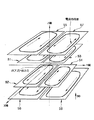
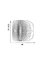
図2に、一般的な円筒方式のY軸コイルセットの構造を示している。図3に、垂直方式のY軸コイルセットの構造を示している。Y軸コイルセットは、円筒方式、垂直方式、その他の方式のいずれでも構わない。図4に、図2、図3の1つのコイルのコイルパターンの一例を示している。コイルパターンは図4に示したようなスパイラルタイプには限定されない。なお、図2、図3の矢印は電流の向きを表している。この矢印は他の図面でも同様に電流の向きを表している。
【0030】
Y軸コイルセットは、4つの主コイル51〜54と、4つのシールドコイル55〜58とを有する。主コイル51と53とは、X−Y面に関して対称に、Z軸に沿ってアレイされる。主コイル52と54とは、X−Y面に関して対称に、Z軸に沿ってアレイされる。主コイル51と52とは、X−Z面を挟んで向かい合わせに配置される。主コイル53と54とは、X−Z面を挟んで向かい合わせに配置される。
【0031】
主に主コイル51が発生する磁場を外界に対して遮蔽するためのシールドコイル55は、主コイル51の外側に配置される。主に主コイル52が発生する磁場を外界に対して遮蔽するためのシールドコイル56は、主コイル52の外側に配置される。主に主コイル53が発生する磁場を外界に対して遮蔽するためのシールドコイル57は、主コイル53の外側に配置される。主に主コイル54が発生する磁場を外界に対して遮蔽するためのシールドコイル58は、主コイル54の外側に配置される。
【0032】
Y軸コイルセットは、4つのペアを有する。第1のペアは、主コイル51とシールドコイル55とからなる。第2のペアは、主コイル52とシールドコイル56とからなる。第3のペアは、主コイル53とシールドコイル57とからなる。第4のペアは、主コイル54とシールドコイル58とからなる。1つのペアを構成する主コイルとシールドコイルとは、両者の物理的距離が最も近く、磁気的結合が最も強いコイルどうしが選択される。あるシールドコイルは、それとペアを構成する主コイルからの磁場を外界に対して遮蔽する効果が、対応しない主コイルからの磁場を外界に対して遮蔽する効果よりも大きい、
4つの主コイル51〜54と4つのシールドコイル55〜58とは、1つのペアを1つの単位として複数のグループへ割当てられる。
【0033】
図5に示すように、第1のグループは第1のペア(51,55)と第2のペア(52,56)とからなり、第2のグループは第3のペア(53,57)と第4のペア(54,57)とからなる。
【0034】
また、図6に示すように、第1のグループは第1のペア(51,55)と第3のペア(53,57)とからなり、第2のグループは第2のペア(52,56)と第4のペア(54,58)とからなるようにしてもよい。
【0035】
さらに、図7に示すように、第1のグループは第1のペア(51,55)と第4のペア(54,58)とからなり、第2のグループは第2のペア(52,56)と第3のペア(53,57)とからなるようにしてもよい。
【0036】
第1のアンプ28は、Y軸コイルセットの第1のグループに含まれる2つの主コイルと2つのシールドコイルとに電流を供給する。第2のアンプ29は、Y軸コイルセットの第2のグループに含まれる2つの主コイルと2つのシールドコイルとに電流を供給する。
【0037】
なお、X軸コイルセットは、Y軸コイルセットと同様に、4つの主コイルと、4つのシールドコイルとを有し、その構造はY軸コイルセットをZ軸に関して90°回転したものに相当する。X軸コイルセットの4つの主コイルと4つのシールドコイルとを2つのグループに分割することは、上述したY軸コイルセットのグループ分けと同一であるので、説明を省略する。また、第1のアンプ26は、X軸コイルセットの第1のグループに含まれる2つの主コイルと2つのシールドコイルとに電流を供給し、第2のアンプ27は、X軸コイルセットの第2のグループに含まれる2つの主コイルと2つのシールドコイルとに電流を供給する。
【0038】
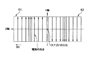
図8に、一般的な円筒方式のZ軸コイルセットの2つの主コイルを示している。図9に、一般的な円筒方式のZ軸コイルセットの2つのシールドコイルを示している。図10に、垂直方式のZ軸コイルセットの2つの主コイルと2つのシールドコイルとを示している。なお、図8、図9、図10において矢印は電流の向きを表している。コイルパターンはソレノイドタイプやスパイラルタイプには限定されない。Z軸コイルセットは、2つの主コイル61〜62と、2つのシールドコイル63〜64とを有する。主コイル61と62とは、X−Y面に関して対称に、Z軸に沿ってアレイされる。主に主コイル61が発生する磁場を外界に対して遮蔽するためのシールドコイル63は、主コイル61の外側に配置される。主に主コイル62が発生する磁場を外界に対して遮蔽するためのシールドコイル64は、主コイル62の外側に配置される。
【0039】
Z軸コイルセットは、2つのペアを有する。第1のペアは、主コイル61とシールドコイル63とからなる。第2のペアは、主コイル62とシールドコイル64とからなる。図11に示すように、第1のグループは一方のペア(61,63)からなり、第2のグループは他方のペア(62,64)からなる。
【0040】
第1のアンプ30は、Z軸コイルセットの第1のグループに含まれる1つの主コイルと1つのシールドコイルとに電流を供給し、第2のアンプ31は、Z軸コイルセットの第2のグループに含まれる1つの主コイルと1つのシールドコイルとに電流を供給する。
【0041】
このようにコイルセットの複数の主コイルと複数のシールドコイルとを複数のグループに分割し、グループ各々に別々のアンプから個別に電流を供給するようにしたので、1つのアンプから見た1グループのインピーダンスは低下する。したがって、比較的低性能のアンプでも、エコープレナー法等の超高速イメージング法が要求する例えば30mT/mという高い磁場を0. 1msecという非常に短い時間で立ち上げることができる。
【0042】
また、1つの主コイルとその主コイルからの磁場を外界に対して主に遮蔽する1つのシールドコイルとを1つのペア、つまり物理的距離が最も近く、磁気的結合が最も強い2つのコイルを1つのペアとして、このペアを崩さないようにペア単位でグループ分けを行ったので、インピーダンスを好適に低下させることができる。
【0043】
なお、コイルセットを、主コイルのみのグループと、シールドコイルのみのグループとに分割するようにしてもよい。この場合、遮蔽精度を向上させるために、シールドコイルに供給する電流を、主コイルに供給する電流に対して意図的に相違させることができる。
【0044】
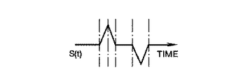
次に、同じ軸のコイルセットに含まれるペアの遅延回路(33と34、35と36、37と38)の遅延時間の差Δtの設定について説明する。図12にこの設定のためのユニットの構成を示している。第1、第2のグループの回路にそれぞれ電流計71,72が設けられる。電流計71は、第1のグループの回路に流れる電流の時間波形A1(t)を検出する(図13参照)。電流計72は第2のグループの回路に流れる電流の時間波形A2(t)を検出する(図14参照)。
【0045】
差分プロセッサ73は、差分波形S(t) を計算するために、A1(t)からA2(t)を引き算する。2つのグループ各々からの磁場の発生時刻がずれているとき、差分波形S(t) は図15に示すように、2つのスパイクを含む。2つのグループ各々からの磁場の発生時刻が完全に同期しているとき、差分波形S(t) は図16に示すように、ゼロで安定する。
【0046】
遅延時間コントローラ74は、差分波形S(t) が図16に示した状態になる又はその状態に近似するように、遅延回路33,34各々の遅延時間Δt1 ,Δt2 の差Δtを調整する。この調整は、差分波形S(t) をディスプレイに表示して、オペレータがマニュアルで行うようにしてもよい。なおこの遅延時間は設定後の経時的変動はないとみなすことができれば、設定後に、電流計71,72、差分プロセッサ73、遅延時間コントローラ74を取り去ってもよい。
【0047】
このような遅延時間の調整により、2つのグループ各々から磁場を同時に発生することができる。
なお、上述した実施形態は次のように変形することができる。
【0048】
上述では、主コイルとこの主コイルと磁気的結合の最も強いシールドコイルとをペアとして、ペアを崩さないようにグループに分割すると説明したが、ペアに関わりなく複数の主コイルと複数のシールドコイルとを任意の組み合わせで複数のグループに分割するようにしてもよい。また、複数の主コイルだけで1つのグループを構成し、複数のシールドコイルだけで1つのグループを構成するようにしてもよい。この場合、複数の主コイルと複数のシールドコイルとに供給する電流の大きさを個別に調整して、遮蔽効果を適正化できるという効果が得られる。
【0049】
また、上述では、1つのコイルセットに含まれる2つのグループで1つの波形整形器を共有する構成を説明したが、図17に示すように2つのグループ各々に1つずつ波形整形器411 ,412 を設けるようにしてもよい。さらに、図18に示すように、遅延回路35,36と、波形整形器411 ,412 とを入れ替えて、シーケンサ19からの矩形信号に対して遅延をかけた後に、波形整形するようにしてもよい。
【0050】
また、同じ軸のコイルセットに対応する複数の遅延回路の中において、最も磁場の発生タイミングが遅い少なくとも1つのグループ(このグループからの磁場の発生タイミングを基準として他のグループに対応する遅延時間が調整される)に対応する少なくとも1つの遅延回路を構成要素から排除することができる。
【0051】
また、同じ軸のコイルセットに含まれる複数のグループから磁場が同時に発生されるという目的を達成するために、上述したような信号遅延の代わりに、最も早く磁場が発生するグループの磁場発生タイミングを基準として、他の遅いグループに対応するアンプへの制御信号の供給タイミングを早めるようにしてもよい。
【0052】
また、上述では、遅延時間調整のために、グループ各々の電流を計測するようにしたが、磁場中心での磁場強度の時間変化を計測し、これに基づいて遅延時間を調整するようにしてもよい。グループ各々からの磁場が同期して発生するなら、この磁場中心での磁場強度は、静磁場強度で安定していなければならない。したがって、この磁場中心での磁場強度が静磁場強度で安定するように、遅延時間を調整すればよい。
【0053】
また、上述では、Y軸コイルセット(X軸コイルセット)を2つのグループに分割すると説明したが、図19に示すように、Y軸コイルセットを3つのグループに分割し、3つのグループを3つのアンプ81〜83で個別に駆動するようにしてもよい。3つのグループに対する4つの主コイルと4つのシールドコイルとの割振りは、ペアを1単位とすることを最適とするが、これに限定されない。
【0054】
また、図20に示すように、Y軸コイルセット(X軸コイルセット)を4つのグループに分割し、4つのグループを4つのアンプ81〜94で個別に駆動するようにしてもよい。4つのグループに対する4つの主コイルと4つのシールドコイルとの割振りは、主コイルとそれからの磁場を外界に対して主に遮蔽するシールドコイルとのペアを1つのグループとすることを最適とするが、これに限定されない。
【0055】
さらに、同軸に対応する複数の主コイルと複数のシールドコイルとを4を越える複数のグループ、例えば8グループに分割し、個々に駆動するようにしてもよい。この場合、1つのコイルは複数、例えば2つのコイルセグメントに分離される。第1の方法では、図21に示すように、1つのコイルは当該1つのコイルの中心付近でZ軸方向に関して2つのコイルセグメント131,132に分離される。図22に示すように、一方のコイルセグメント131の一部は折り返され、その上に他方のコイルセグメント132の一部が重ねられることにより、連結される。このような重ね合わせ連結は、一方のコイルセグメント131が折り返された部分から発生する磁場が、他方のコイルセグメント132の重ね合わされる部分から発生する磁場によってキャンセルされ、2つのコイルセグメント131,132のメイン部分から発生する磁場の合成磁場の磁場分布が、図4に示されるような1つのコイルの発生する磁場の磁場分布とほぼ等価となる。
【0056】
また、1つのコイルを2つのコイルセグメントに分離する第2の方法は、図23に示すように、1つのコイルを、その中央部分のコイルセグメント131と、その周囲のコイルセグメント132とに分割する方法である。また、1つのコイルを2つのコイルセグメントに分離する第3の方法は、図24に示すように、2つのコイルセグメント131、132を2重螺旋にパターンするという方法である。これら図23、図24のコイルセグメントの分離方法は、図21のような連結の工夫を不要とする。
【0057】
図21、図23、図24のいずれかの方法により、図25に示すように、Y軸コイルセット(X軸コイルセット)の4つの主コイルは8つのコイルセグメント51−131、52−131、53−131、54−131、51−132、52−132、53−132、54−132に分離され、また4つのシールドコイルは、8つのコイルセグメント55−131、56−131、57−131、58−131、55−132、56−132、57−132、58−132に分離される。合計16のコイルセグメントに分離されたY軸コイルセットは、主コイルのコイルセグメントと、それからの磁場を外界に対して主に遮蔽するシールドコイルのコイルセグメントとを1つのペアとして1つのグループを構成し、全部で8つのグループに分割される。8つのグループを個別に駆動するように8つのアンプ141〜148が設けられ、8つのアンプ141〜148に対応して8つの遅延回路151〜158が設けられる。
【0058】
Z軸コイルセットのコイル各々も、同様にコイルセグメントに分離されるろとが可能である。図26に示すように、1つのソレノイドコイルが略中央で2つのコイルセグメント161,162に分離される。または、2つのコイルセグメント161,162を2重螺旋に形成して、1つのコイルを構成するようにしてよい。
【0059】
図27に示すように、Z軸コイルセットの2つの主コイルは4つのコイルセグメント61−161,62−161,61−162,62−162に分離され、また2つのシールドコイルは、4つのコイルセグメント63−161,64−161,63−162,64−162に分離される。合計8つのコイルセグメントに分離されたZ軸コイルセットは、主コイルのコイルセグメントと、それからの磁場を外界に対して主に遮蔽するシールドコイルのコイルセグメントとを1つのペアとして1つのグループを構成し、全部で4つのグループに分割される。4つのグループを個別に駆動するように4つのアンプ171〜174が設けられ、4つのアンプ171〜174に対応して4つの遅延回路181〜184が設けられる。
【0060】
X,Y,Z各軸のコイルセットを分割するグループ数やその割振りは、上述に限定されず、任意に変更することができる。
また、図28に示すように、例えば4つのシールドコイル55〜58の電流を、4つの補助アンプ101〜104により補正して、所望の遮蔽効果を得るようにしてもよい。勿論、主コイル51〜54に補助アンプを設け、所望の遮蔽効果を得るようにしてもよい。
【0061】
以上のように、本実施形態によれば、複数の主コイルと複数のシールドコイルとは複数のグループに分割され、複数のグループを個別に駆動するようにしたので、1個のアンプから見た負荷インピーダンスは数分の一に低減する。従って、比較的低出力でコストの安価なアンプでも、エコープレナー法に適用できるような例えば30mT/mという高い強度の傾斜磁場を0. 1msecという非常に短い時間で立ち上げることができる。
本発明は、上述した実施形態に限定されることなく種々変形して実施可能であるのは勿論である。
【0062】
【発明の効果】
磁気共鳴イメージング装置は、静磁場に置かれた被検体に、傾斜磁場と高周波磁場とを印加することにより、原子核を励起し、磁気共鳴信号を発生させる。磁気共鳴信号に基づいて、磁気共鳴画像が再構成される。傾斜磁場は傾斜磁場コイルにより形成される。高速な交番磁場を必要とするエコープレナー法等の高速イメージング法では、能動的遮蔽型傾斜磁場コイル(Active Shielded Gradient Coil) 、つまり主コイルから発生した磁場をシールドコイルにより外界に対して磁気的に遮蔽する傾斜磁場コイルを使用するのが好ましい。主コイルとシールドコイルとを1つのアンプで駆動して、比較的高い強度の傾斜磁場を短時間で立ち上げることは、非常に困難である。主コイルとシールドコイルとを複数のグループに分け、グループ各々に対して個別に電流を供給することにより、比較的高い強度の傾斜磁場を短時間で立ち上げることが可能となる。
【図面の簡単な説明】
【図1】本発明の実施例による磁気共鳴イメージング装置の構成図。
【図2】図1のGy コイルセットの構造図。
【図3】図1のGy コイルセットの他の構造図。
【図4】図2、図3の1つのコイルのコイルパターンの一例を示す図。
【図5】図1のGy コイルセットの2グループへの割当てと、シーケンサから波形整形器及び遅延回路を経てアンプまでの信号変化を示す図。
【図6】図1のGy コイルセットの他のグループ割りを示す図。
【図7】図1のGy コイルセットのさらに他のグループ割りを示す図。
【図8】図1のGz コイルセットの主コイルの構造図。
【図9】図1のGz コイルセットのシールドコイルの構造図。
【図10】図1のGz コイルセットの他の構造図。
【図11】図1のGz コイルセットのグループ割りと、シーケンサから波形整形器及び遅延回路を経てアンプまでの信号変化を示す図。
【図12】図1のGz コイルセットに対応する2つの遅延回路各々の遅延時間を調整するためのユニットの構成図。
【図13】図12のA1(t)を示す図。
【図14】図12のA2(t)を示す図。
【図15】図12のS(t) を示す図。
【図16】遅延時間調整後の理想的なS(t) を示す図。
【図17】図1のGy コイルセットに対応する波形整形器及び遅延回路の他の構成例を示す図。
【図18】図1のGy コイルセットに対応する波形整形器及び遅延回路のさらに他の構成例を示す図。
【図19】図1のGy コイルセットを3グループに分割するグループ割りを示す図。
【図20】図1のGy コイルセットを4グループに分割するグループ割りを示す図。
【図21】図1のGy コイルセットのコイル各々を2つのコイルセグメントに分離したコイルパターンを示す図。
【図22】図21の実装された2つのコイルセグメントの側面図。
【図23】1つのコイルを2つのコイルセグメントに分離した他のコイルパターンを示す図。
【図24】1つのコイルを2つのコイルセグメントに分離した他のコイルパターンを示す図。
【図25】図1のGy コイルセットのコイル各々を2つのコイルセグメントに分離して8グループに分割するグループ割りを示す図。
【図26】図1のGz コイルセットのコイル各々を2つのコイルセグメントに分離したコイルパターンを示す図。
【図27】図1のGz コイルセットのコイル各々を2つのコイルセグメントに分離して4グループに分割するグループ割りを示す図。
【図28】図20の4グループの補助アンプを示す図。
【図29】図1は、従来の傾斜磁場コイルユニットの回路図。
【符号の説明】
11…磁石架台、
12…静磁場コイル、
13…高周波コイル、
14…傾斜磁場コイルユニット、
15…寝台、
16…X軸コイルセット、
17…Y軸コイルセット、
18…Z軸コイルセット、
19…シーケンサ、
20…静磁場アンプ、
21…送信器、
22…受信器、
23…プロセッサ、
24…ディスプレイ、
25…傾斜磁場電源、
26…アンプ、
27…アンプ、
28…アンプ、
29…アンプ、
30…アンプ、
31…アンプ、
32…遅延回路群、
33…遅延回路、
34…遅延回路、
35…遅延回路、
36…遅延回路、
37…遅延回路、
38…遅延回路、
39…波形整形器群、
40…波形整形器、
41…波形整形器、
42…波形整形器、
43…コンソール、
44…システムコントローラ。[0001]
TECHNICAL FIELD OF THE INVENTION
The present invention relates to a magnetic resonance imaging apparatus that excites nuclei in a subject with a high-frequency magnetic field and reconstructs a magnetic resonance image based on a magnetic resonance signal from the excited nuclei.
[0002]
[Prior art]
In a magnetic resonance imaging apparatus, a gradient magnetic field unit that forms a gradient magnetic field is one of important components.
The gradient magnetic field unit has three coil sets and three amplifiers so that gradient magnetic fields of three orthogonal axes (X, Y, Z) can be individually formed.
[0003]
The X-axis gradient magnetic field GX, the Y-axis gradient magnetic field GY, and the Z-axis gradient magnetic field GZ are each independently or combined, and are read-out gradient magnetic fields (GR) for spatially encoding the frequency of the magnetic resonance signal. , A phase encoding gradient magnetic field (GE) for spatially encoding the phase of a magnetic resonance signal, and a slice selection gradient magnetic field (GS) for selecting an imaging region of a subject.
[0004]
The gradient magnetic field coils are generally configured to form a magnetic field distribution such that the magnetic field strength changes linearly between the coil pairs (imaging region). In order to prevent the gradient magnetic field from leaking to the outside world and generating eddy currents in the surrounding conductor, a magnetic field opposite to the magnetic field generated by the main coil is provided outside the main coil for generating the gradient magnetic field. BACKGROUND ART A gradient magnetic field coil device called an active shield type gradient magnetic coil device in which a generated magnetic field shielding coil is arranged is known. FIG. 29 shows a circuit for forming a uniaxial gradient magnetic field. This circuit comprises main coils 1-4 for forming a gradient magnetic pole, shield coils 5-8 for magnetically shielding the magnetic field generated from the main coils 1-4 from the outside, And an amplifier for supplying current to the coil. On the other hand, in recent years, an ultra-high-speed imaging method typified by an echo planar imaging method (Echo Planar Imaging method (EPI method)) has been put to practical use. This high-speed imaging method can collect a plurality of echoes necessary for reconstructing one magnetic image in the order of several tens of milliseconds, and its usefulness is high.
[0005]
However, in a so-called standard spin echo method, for example, a gradient magnetic field with a magnetic field strength of 10 mT / m may be started up in 1 msec. It is required to start up in lmsec and to alternate at high speed. In order to suppress the eddy current generated in the surrounding conductor due to such a high-speed alternating magnetic field, an active shield type gradient magnetic coil device is indispensable.
[0006]
However, the main coils 1-4 and the shield coils 5-8 connected in series are driven by one
[0007]
The use of a high-power amplifier improves insulation and prevents magnetic coupling between the gradient coil and surrounding coils, such as static magnetic field coils, static magnetic field correction coils, and RF coils. It requires various improvements such as doing.
[0008]
It is to be noted that the space between the main coil and the shield coil is widened to lower the impedance of the gradient coil even a little, thereby alleviating the required specifications of the amplifier. However, this is not preferable because the size of the magnet base is increased. In addition, the problem of the magnetic coupling can be alleviated by increasing the space between the gradient magnetic field coil and the static magnetic field coil and the space between the gradient magnetic field coil and the RF coil. It is not preferable because the frame becomes large.
[0009]
[Problems to be solved by the invention]
SUMMARY OF THE INVENTION It is an object of the present invention to provide a magnetic resonance imaging apparatus which can satisfy a demand for an ultra-high-speed imaging method such as an echo planar method with a relatively low-output gradient magnetic field amplifier.
[0010]
[Means for Solving the Problems]
A magnetic resonance imaging apparatus according to the present invention includes: a unit configured to form a static magnetic field in an imaging region; a first gradient magnetic field generating unit configured to form a gradient magnetic field related to a first axis in the imaging region; Second gradient magnetic field generating means for forming a gradient magnetic field about two axes, third gradient magnetic field generating means for forming a gradient magnetic field about a third axis in the imaging region, and an object placed in the imaging region Means for generating a high-frequency magnetic field, means for detecting a magnetic resonance signal from the excited nucleus, and reconstructing a magnetic resonance image based on the detected magnetic resonance signal in order to excite the nuclei. Means, the first , Second and At least one of the third gradient magnetic field generating means includes: A plurality of groups in which at least one main coil for forming the gradient magnetic field and at least one shield coil for magnetically shielding a magnetic field generated from the main coil from the outside are connected in series; Driving means for individually supplying current to each of the groups; It is characterized by having.
[0013]
BEST MODE FOR CARRYING OUT THE INVENTION
Hereinafter, preferred embodiments of the magnetic resonance imaging apparatus of the present invention will be described with reference to the drawings.
FIG. 1 is a configuration diagram of the magnetic resonance imaging apparatus of the present embodiment. The
[0014]
For convenience of description, three orthogonal axes (X axis, Y axis, and Z axis) having the origin at the center of the imaging region are defined as follows. The Z axis is parallel to the static magnetic field B0. The X axis is orthogonal to the Z axis. The Y axis is orthogonal to the X axis and the Z axis.
[0015]
Further, the
[0016]
Further, the
[0017]
If the static
[0018]
The
[0019]
The gradient magnetic
[0020]
Each of the three coil sets has a plurality of main coils for forming a corresponding gradient magnetic field, and a plurality of shield coils for magnetically shielding a magnetic field generated from the plurality of main coils from the outside.
[0021]
Although the main coil and the shield coil are referred to here for convenience, only the main coil is responsible for forming the gradient magnetic field, and not only the shield coil is responsible for forming the shielding magnetic field.
[0022]
The magnetic field formed by the main coil and the shield coil is the gradient magnetic field to be obtained.The main coil is mainly responsible for forming the gradient magnetic field in the imaging area, and the shield coil shields the magnetic field from leaking to the outside world. It is mainly responsible. The names of the main coil and the shield coil are properly used in this sense.
[0023]
The plurality of main coils and the plurality of shield coils constituting each of the three coil sets are divided into a plurality of groups, here, first and second groups. The first group includes at least two coils, preferably half of the plurality of main coils and the plurality of shield coils. The second group includes the remaining coils not included in the first group among the plurality of main coils and the plurality of shield coils. Preferably, each of the two groups includes a mixture of at least one main coil and at least one shield coil. A plurality of coils included in the same group are connected in series. Details of the allocation of the plurality of coils to the two groups will be described later.
[0024]
The gradient magnetic
[0025]
The
[0026]
The
[0027]
Here, in the
The
[0028]
The
[0029]
FIG. 2 shows the structure of a general cylindrical Y-axis coil set. FIG. 3 shows the structure of a vertical Y-axis coil set. The Y-axis coil set may be any of a cylindrical type, a vertical type, and other types. FIG. 4 shows an example of the coil pattern of one of the coils shown in FIGS. The coil pattern is not limited to the spiral type as shown in FIG. Note that the arrows in FIGS. 2 and 3 indicate the direction of the current. This arrow similarly indicates the direction of the current in other drawings.
[0030]
The Y-axis coil set has four
[0031]
A
[0032]
The Y-axis coil set has four pairs. The first pair includes a
The four
[0033]
As shown in FIG. 5, the first group includes a first pair (51, 55) and a second pair (52, 56), and the second group includes a third pair (53, 57). It consists of a fourth pair (54, 57).
[0034]
As shown in FIG. 6, the first group includes a first pair (51, 55) and a third pair (53, 57), and the second group includes a second pair (52, 56). ) And a fourth pair (54, 58).
[0035]
Further, as shown in FIG. 7, the first group is composed of a first pair (51, 55) and a fourth pair (54, 58), and the second group is a second pair (52, 56). ) And a third pair (53, 57).
[0036]
The
[0037]
Note that the X-axis coil set has four main coils and four shield coils similarly to the Y-axis coil set, and the structure thereof corresponds to a structure in which the Y-axis coil set is rotated by 90 ° with respect to the Z axis. . Dividing the four main coils and the four shield coils of the X-axis coil set into two groups is the same as the above-described grouping of the Y-axis coil set, and a description thereof will be omitted. Further, the
[0038]
FIG. 8 shows two main coils of a general cylindrical Z-axis coil set. FIG. 9 shows two shield coils of a general cylindrical Z-axis coil set. FIG. 10 shows two main coils and two shield coils of a vertical Z-axis coil set. The arrows in FIGS. 8, 9 and 10 indicate the direction of the current. The coil pattern is not limited to the solenoid type or the spiral type. The Z-axis coil set has two
[0039]
The Z-axis coil set has two pairs. The first pair includes a
[0040]
The
[0041]
As described above, the plurality of main coils and the plurality of shield coils of the coil set are divided into a plurality of groups, and current is individually supplied to each group from a separate amplifier. The impedance of the device decreases. Therefore, even with a relatively low-performance amplifier, a high magnetic field of, for example, 30 mT / m required by an ultra-high-speed imaging method such as an echo planar method is required. It can be started up in a very short time of 1 msec.
[0042]
Also, one pair of one main coil and one shield coil that mainly shields the magnetic field from the main coil from the outside world, that is, two coils having the closest physical distance and the strongest magnetic coupling, As one pair is grouped in pairs so as not to break this pair, the impedance can be suitably reduced.
[0043]
Note that the coil set may be divided into a group including only the main coil and a group including only the shield coil. In this case, in order to improve shielding accuracy, the current supplied to the shield coil can be intentionally made different from the current supplied to the main coil.
[0044]
Next, the setting of the delay time difference Δt between the pair of delay circuits (33 and 34, 35 and 36, 37 and 38) included in the coil set of the same axis will be described. FIG. 12 shows the configuration of a unit for this setting. Ammeters 71 and 72 are provided in the circuits of the first and second groups, respectively. The
[0045]
The
[0046]
The
[0047]
By adjusting such a delay time, a magnetic field can be simultaneously generated from each of the two groups.
The above-described embodiment can be modified as follows.
[0048]
In the above description, the main coil and the shield coil having the strongest magnetic coupling are paired and divided into groups so as not to break the pair. However, regardless of the pair, the plurality of main coils and the plurality of shield coils are divided. May be divided into a plurality of groups by an arbitrary combination. Alternatively, one group may be configured with only a plurality of main coils, and one group may be configured with only a plurality of shield coils. In this case, the magnitude of the current supplied to the plurality of main coils and the plurality of shield coils is individually adjusted, so that the shielding effect can be optimized.
[0049]
In the above description, the configuration in which one waveform shaper is shared by two groups included in one coil set has been described. However, as shown in FIG. 17, one
[0050]
Also, among a plurality of delay circuits corresponding to the coil set of the same axis, at least one group having the latest magnetic field generation timing (delay time corresponding to another group based on the magnetic field generation timing from this group as a reference) At least one delay circuit corresponding to (adjusted) can be eliminated from the component.
[0051]
Also, in order to achieve the purpose of simultaneously generating magnetic fields from a plurality of groups included in the coil set of the same axis, instead of the signal delay as described above, the magnetic field generation timing of the group in which the magnetic field is generated earliest is set. As a reference, the supply timing of the control signal to the amplifier corresponding to another slow group may be advanced.
[0052]
In the above description, the current of each group is measured for adjusting the delay time. However, the time change of the magnetic field strength at the center of the magnetic field may be measured, and the delay time may be adjusted based on this. Good. If the magnetic fields from each of the groups are generated synchronously, the magnetic field strength at the center of this field must be stable at the static magnetic field strength. Therefore, the delay time may be adjusted so that the magnetic field strength at the center of the magnetic field is stabilized at the static magnetic field strength.
[0053]
In the above description, the Y-axis coil set (X-axis coil set) is divided into two groups. However, as shown in FIG. 19, the Y-axis coil set is divided into three groups, and the three groups are divided into three groups. The driving may be performed individually by the two
[0054]
Further, as shown in FIG. 20, the Y-axis coil set (X-axis coil set) may be divided into four groups, and the four groups may be individually driven by four
[0055]
Further, the plurality of main coils and the plurality of shield coils corresponding to the coaxial axis may be divided into a plurality of groups exceeding four, for example, eight groups, and each group may be individually driven. In this case, one coil is divided into a plurality of, for example, two coil segments. In the first method, as shown in FIG. 21, one coil is separated into two
[0056]
In a second method of separating one coil into two coil segments, as shown in FIG. 23, one coil is divided into a
[0057]
As shown in FIG. 25, the four main coils of the Y-axis coil set (X-axis coil set) are divided into eight coil segments 51-131, 52-131, 53-131, 54-131, 51-132, 52-132, 53-132, 54-132, and the four shield coils are divided into eight coil segments 55-131, 56-131, 57-131, 58-131, 55-132, 56-132, 57-132, and 58-132. The Y-axis coil set, which is divided into a total of 16 coil segments, forms one group with the coil segment of the main coil and the coil segment of the shield coil mainly shielding the magnetic field therefrom from the outside as one pair. And is divided into eight groups in total. Eight
[0058]
Each of the coils of the Z-axis coil set can be similarly separated into coil segments. As shown in FIG. 26, one solenoid coil is separated into two
[0059]
As shown in FIG. 27, the two main coils of the Z-axis coil set are separated into four coil segments 61-161, 62-161, 61-162, 62-162, and the two shield coils are four coil segments. Segments 63-161, 64-161, 63-162, 64-162 are separated. The Z-axis coil set divided into a total of eight coil segments constitutes a group with the coil segment of the main coil and the coil segment of the shield coil mainly shielding the magnetic field therefrom from the outside as one pair. Then, it is divided into four groups in total. Four
[0060]
The number of groups into which the coil sets of the X, Y, and Z axes are divided and the allocation thereof are not limited to the above, and can be arbitrarily changed.
Further, as shown in FIG. 28, for example, the current of the four
[0061]
As described above, according to the present embodiment, the plurality of main coils and the plurality of shield coils are divided into a plurality of groups, and the plurality of groups are individually driven. The load impedance is reduced by a factor. Therefore, even a relatively low-power and inexpensive amplifier can produce a high gradient magnetic field of, for example, 30 mT / m, which is applicable to the echo planar method. It can be started up in a very short time of 1 msec.
It is needless to say that the present invention can be implemented with various modifications without being limited to the above embodiment.
[0062]
【The invention's effect】
A magnetic resonance imaging apparatus applies a gradient magnetic field and a high-frequency magnetic field to a subject placed in a static magnetic field to excite atomic nuclei and generate a magnetic resonance signal. A magnetic resonance image is reconstructed based on the magnetic resonance signal. The gradient magnetic field is formed by a gradient coil. In a high-speed imaging method such as an echo planar method that requires a high-speed alternating magnetic field, an active shielded gradient coil (ie, an active shielded gradient coil), that is, a magnetic field generated from a main coil is magnetically shielded from the outside world by a shield coil. Preferably, a shielding gradient coil is used. It is very difficult to drive a main coil and a shield coil with one amplifier to start up a relatively high-intensity gradient magnetic field in a short time. By dividing the main coil and the shield coil into a plurality of groups and supplying a current individually to each group, it is possible to start up a relatively high-intensity gradient magnetic field in a short time.
[Brief description of the drawings]
FIG. 1 is a configuration diagram of a magnetic resonance imaging apparatus according to an embodiment of the present invention.
FIG. 2 is a structural diagram of a Gy coil set of FIG. 1;
FIG. 3 is another structural view of the Gy coil set of FIG. 1;
FIG. 4 is a view showing an example of a coil pattern of one coil shown in FIGS. 2 and 3;
FIG. 5 is a diagram showing allocation of the Gy coil sets of FIG. 1 to two groups, and a signal change from a sequencer to an amplifier via a waveform shaper and a delay circuit.
FIG. 6 is a diagram showing another grouping of the Gy coil set in FIG. 1;
FIG. 7 is a view showing still another group division of the Gy coil set in FIG. 1;
FIG. 8 is a structural diagram of a main coil of the Gz coil set of FIG. 1;
FIG. 9 is a structural diagram of a shield coil of the Gz coil set of FIG. 1;
FIG. 10 is another structural view of the Gz coil set of FIG. 1;
11 is a diagram showing group division of the Gz coil set in FIG. 1 and a signal change from a sequencer to an amplifier via a waveform shaper and a delay circuit.
12 is a configuration diagram of a unit for adjusting the delay time of each of two delay circuits corresponding to the Gz coil set of FIG. 1;
FIG. 13 is a diagram showing A1 (t) in FIG. 12;
FIG. 14 is a diagram showing A2 (t) in FIG. 12;
FIG. 15 is a view showing S (t) in FIG. 12;
FIG. 16 is a diagram showing ideal S (t) after delay time adjustment.
FIG. 17 is a diagram showing another configuration example of the waveform shaper and the delay circuit corresponding to the Gy coil set of FIG. 1;
FIG. 18 is a diagram showing still another configuration example of the waveform shaper and the delay circuit corresponding to the Gy coil set in FIG. 1;
FIG. 19 is a diagram showing group division for dividing the Gy coil set of FIG. 1 into three groups.
FIG. 20 is a diagram showing group division for dividing the Gy coil set of FIG. 1 into four groups.
FIG. 21 is a diagram showing a coil pattern in which each coil of the Gy coil set of FIG. 1 is separated into two coil segments.
FIG. 22 is a side view of the mounted two coil segments of FIG. 21.
FIG. 23 is a view showing another coil pattern in which one coil is divided into two coil segments.
FIG. 24 is a diagram showing another coil pattern in which one coil is divided into two coil segments.
FIG. 25 is a view showing a group division in which each coil of the Gy coil set in FIG. 1 is divided into two coil segments and divided into eight groups.
FIG. 26 is a diagram showing a coil pattern in which each coil of the Gz coil set of FIG. 1 is separated into two coil segments.
FIG. 27 is a diagram showing group division in which each coil of the Gz coil set in FIG. 1 is divided into two coil segments and divided into four groups.
FIG. 28 is a diagram showing four groups of auxiliary amplifiers in FIG. 20;
FIG. 1 is a circuit diagram of a conventional gradient magnetic field coil unit.
[Explanation of symbols]
11 ... magnet mount,
12: Static magnetic field coil,
13 ... High frequency coil,
14 ... Gradient magnetic field coil unit,
15 ... Bed,
16 ... X-axis coil set,
17 ... Y-axis coil set,
18 ... Z-axis coil set,
19 ... sequencer,
20: Static magnetic field amplifier,
21 ... Transmitter,
22 ... receiver,
23 ... Processor,
24 ... Display,
25 ... Gradient magnetic field power supply
26 ... Amplifier,
27 ... Amplifier,
28 ... Amplifier,
29 ... Amplifier,
30 ... Amplifier,
31 ... Amplifier,
32 ... delay circuit group,
33 ... delay circuit,
34 ... delay circuit,
35 ... delay circuit,
36 ... Delay circuit,
37 ... delay circuit,
38 ... Delay circuit,
39 ... waveform shaper group,
40 ... waveform shaper,
41 ... waveform shaper,
42 ... waveform shaper,
43 ... Console,
44 ... System controller.
Claims (18)
前記撮影領域内に第1軸に関する傾斜磁場を形成する第1の傾斜磁場発生手段と、
前記撮影領域内に第2軸に関する傾斜磁場を形成する第2の傾斜磁場発生手段と、
前記撮影領域内に第3軸に関する傾斜磁場を形成する第3の傾斜磁場発生手段と、
前記撮影領域内に置かれた被検体の原子核を励起するために、高周波磁場を発生する手段と、
前記励起された原子核からの磁気共鳴信号を検出する手段と、
前記検出された磁気共鳴信号に基づいて、磁気共鳴画像を再構成する手段とを備え、
前記第1、第2及び第3の傾斜磁場発生手段の少なくとも1つは、前記傾斜磁場を形成するための少なくとも1つの主コイルと、前記主コイルから発生された磁場を外界に対して磁気的に遮蔽するための少なくとも1つのシールドコイルとが直列接続された複数のグループと、前記グループ各々に対して個別に電流を供給する駆動手段とを有することを特徴とする磁気共鳴イメージング装置。Means for forming a static magnetic field in the imaging region;
First gradient magnetic field generation means for forming a gradient magnetic field about a first axis in the imaging region;
Second gradient magnetic field generating means for forming a gradient magnetic field about a second axis in the imaging region;
Third gradient magnetic field generation means for forming a gradient magnetic field about a third axis in the imaging region;
Means for generating a high-frequency magnetic field for exciting atomic nuclei of the subject placed in the imaging region,
Means for detecting a magnetic resonance signal from the excited nuclei,
Means for reconstructing a magnetic resonance image based on the detected magnetic resonance signal,
At least one of the first , second, and third gradient magnetic field generating means includes at least one main coil for forming the gradient magnetic field, and a magnetic field generated from the main coil, which is magnetically generated with respect to the outside. A magnetic resonance imaging apparatus comprising: a plurality of groups in which at least one shield coil for shielding a plurality of groups is connected in series; and a driving unit that individually supplies current to each of the groups .
Priority Applications (2)
| Application Number | Priority Date | Filing Date | Title |
|---|---|---|---|
| JP19347696A JP3556052B2 (en) | 1995-07-27 | 1996-07-23 | Magnetic resonance imaging system |
| US08/687,205 US5867027A (en) | 1995-07-27 | 1996-07-25 | Magnetic resonance imaging apparatus |
Applications Claiming Priority (3)
| Application Number | Priority Date | Filing Date | Title |
|---|---|---|---|
| JP19161295 | 1995-07-27 | ||
| JP19347696A JP3556052B2 (en) | 1995-07-27 | 1996-07-23 | Magnetic resonance imaging system |
| JP7-191612 | 1996-07-27 |
Publications (2)
| Publication Number | Publication Date |
|---|---|
| JPH0994244A JPH0994244A (en) | 1997-04-08 |
| JP3556052B2 true JP3556052B2 (en) | 2004-08-18 |
Family
ID=26506799
Family Applications (1)
| Application Number | Title | Priority Date | Filing Date |
|---|---|---|---|
| JP19347696A Expired - Fee Related JP3556052B2 (en) | 1995-07-27 | 1996-07-23 | Magnetic resonance imaging system |
Country Status (2)
| Country | Link |
|---|---|
| US (1) | US5867027A (en) |
| JP (1) | JP3556052B2 (en) |
Families Citing this family (13)
| Publication number | Priority date | Publication date | Assignee | Title |
|---|---|---|---|---|
| US7233147B2 (en) * | 2001-07-20 | 2007-06-19 | Invivo Corporation | Method and apparatus for magnetic resonance imaging incorporating a spiral coil |
| US7162302B2 (en) * | 2002-03-04 | 2007-01-09 | Nanoset Llc | Magnetically shielded assembly |
| US20050260331A1 (en) * | 2002-01-22 | 2005-11-24 | Xingwu Wang | Process for coating a substrate |
| US20040225213A1 (en) * | 2002-01-22 | 2004-11-11 | Xingwu Wang | Magnetic resonance imaging coated assembly |
| US7239143B2 (en) * | 2003-05-20 | 2007-07-03 | Koninklijke Philips Electronics N.V. | Digital magnetic resonance gradient pre-emphasis |
| DE102004006322B4 (en) * | 2004-02-10 | 2013-09-12 | RAPID Biomedizinische Geräte RAPID Biomedical GmbH | Imaging device for use of nuclear magnetic resonance |
| GB0820043D0 (en) * | 2008-10-31 | 2008-12-10 | Emscan Ltd | Electromagnet assembly |
| JP5010623B2 (en) * | 2009-02-09 | 2012-08-29 | 株式会社東芝 | Coil device for magnetic resonance diagnostic equipment |
| JP2012024451A (en) * | 2010-07-27 | 2012-02-09 | Hitachi Medical Corp | Gradient magnetic field coil device and magnetic resonance imaging apparatus |
| BR112014015024A2 (en) | 2011-12-23 | 2017-06-13 | Koninklijke Philips Nv | rm device |
| JP5819215B2 (en) * | 2012-02-17 | 2015-11-18 | 株式会社日立メディコ | Gradient magnetic field coil and magnetic resonance imaging apparatus |
| JP5974391B2 (en) | 2013-01-16 | 2016-08-23 | 株式会社日立製作所 | Magnetic resonance imaging apparatus and timing deviation detection method thereof |
| DE102020200013A1 (en) * | 2020-01-03 | 2021-07-08 | Siemens Healthcare Gmbh | Magnetic resonance device and method for operating a magnetic resonance device, computer program and electronically readable data carrier |
Family Cites Families (7)
| Publication number | Priority date | Publication date | Assignee | Title |
|---|---|---|---|---|
| EP0216590B2 (en) * | 1985-09-20 | 2001-06-06 | Btg International Limited | Magnetic field screens |
| US4737716A (en) * | 1986-02-06 | 1988-04-12 | General Electric Company | Self-shielded gradient coils for nuclear magnetic resonance imaging |
| US4733189A (en) * | 1986-06-03 | 1988-03-22 | Massachusetts Institute Of Technology | Magnetic resonance imaging systems |
| DE3732660A1 (en) * | 1986-09-29 | 1988-04-07 | Toshiba Kawasaki Kk | MAGNETIC RESONANCE IMAGING SYSTEM |
| JPS6458247A (en) * | 1987-08-29 | 1989-03-06 | Fuji Electric Co Ltd | Uniform magnetic field coil |
| GB9016184D0 (en) * | 1990-07-24 | 1990-09-05 | Oxford Magnet Tech | Magnet assembly |
| EP0560396B1 (en) * | 1992-03-13 | 2001-11-07 | Kabushiki Kaisha Toshiba | Nuclear magnetic resonance imaging with improved image quality and operation efficiency |
-
1996
- 1996-07-23 JP JP19347696A patent/JP3556052B2/en not_active Expired - Fee Related
- 1996-07-25 US US08/687,205 patent/US5867027A/en not_active Expired - Lifetime
Also Published As
| Publication number | Publication date |
|---|---|
| JPH0994244A (en) | 1997-04-08 |
| US5867027A (en) | 1999-02-02 |
Similar Documents
| Publication | Publication Date | Title |
|---|---|---|
| JP3556052B2 (en) | Magnetic resonance imaging system | |
| US6479999B1 (en) | Efficiently shielded MRI gradient coil with discretely or continuously variable field of view | |
| US6538443B2 (en) | MRI gradient coil with variable field of view and apparatus and methods employing the same | |
| JP4588830B2 (en) | RF coil array device for vertical magnetic field MRI | |
| KR20010051663A (en) | Temperature compensated nmr magnet and method of operation therefor | |
| JPH0243493B2 (en) | ||
| KR101630634B1 (en) | Gradient-independent shim coil for a local coil of a magnetic resonance device | |
| US20140184226A1 (en) | System and apparatus for active high order shimming | |
| US6822451B2 (en) | Non-coupling magnetic sheilding coil | |
| JPH08206094A (en) | Nuclear spin tomography device | |
| EP0154996B1 (en) | Magnetic resonance imaging apparatus using shim coil correction | |
| US6313630B1 (en) | Modular gradient system for MRI system | |
| US20140184222A1 (en) | Matrix shim coil apparatus | |
| US6680612B1 (en) | Gradient coil apparatus for magnetic resonance imaging | |
| US10254362B2 (en) | Magnetic resonance imaging matrix shim coil system and method | |
| US6466017B1 (en) | MRI system with modular gradient system | |
| JP3705996B2 (en) | Magnetic resonance imaging device | |
| US7477055B1 (en) | Apparatus and method for coupling coils in a superconducting magnet | |
| EP0850422B1 (en) | Mr device with means for reducing the effects of concomitant field gradients | |
| JP2592920B2 (en) | Superconducting magnet for magnetic resonance imaging | |
| JP4502488B2 (en) | Magnetic resonance imaging device | |
| JPH10262947A (en) | Magnetic resonance examination system | |
| JPS63271910A (en) | Gradient magnetic field generating device for mri | |
| JP2000232967A (en) | Coil device for magnetic resonance diagnostic device | |
| JPH04288138A (en) | Magnetic resonance device |
Legal Events
| Date | Code | Title | Description |
|---|---|---|---|
| TRDD | Decision of grant or rejection written | ||
| A01 | Written decision to grant a patent or to grant a registration (utility model) |
Free format text: JAPANESE INTERMEDIATE CODE: A01 Effective date: 20040427 |
|
| A61 | First payment of annual fees (during grant procedure) |
Free format text: JAPANESE INTERMEDIATE CODE: A61 Effective date: 20040511 |
|
| FPAY | Renewal fee payment (event date is renewal date of database) |
Free format text: PAYMENT UNTIL: 20090521 Year of fee payment: 5 |
|
| FPAY | Renewal fee payment (event date is renewal date of database) |
Free format text: PAYMENT UNTIL: 20090521 Year of fee payment: 5 |
|
| FPAY | Renewal fee payment (event date is renewal date of database) |
Free format text: PAYMENT UNTIL: 20100521 Year of fee payment: 6 |
|
| FPAY | Renewal fee payment (event date is renewal date of database) |
Free format text: PAYMENT UNTIL: 20100521 Year of fee payment: 6 |
|
| FPAY | Renewal fee payment (event date is renewal date of database) |
Free format text: PAYMENT UNTIL: 20110521 Year of fee payment: 7 |
|
| FPAY | Renewal fee payment (event date is renewal date of database) |
Free format text: PAYMENT UNTIL: 20110521 Year of fee payment: 7 |
|
| FPAY | Renewal fee payment (event date is renewal date of database) |
Free format text: PAYMENT UNTIL: 20120521 Year of fee payment: 8 |
|
| FPAY | Renewal fee payment (event date is renewal date of database) |
Free format text: PAYMENT UNTIL: 20120521 Year of fee payment: 8 |
|
| FPAY | Renewal fee payment (event date is renewal date of database) |
Free format text: PAYMENT UNTIL: 20130521 Year of fee payment: 9 |
|
| FPAY | Renewal fee payment (event date is renewal date of database) |
Free format text: PAYMENT UNTIL: 20130521 Year of fee payment: 9 |
|
| FPAY | Renewal fee payment (event date is renewal date of database) |
Free format text: PAYMENT UNTIL: 20140521 Year of fee payment: 10 |
|
| LAPS | Cancellation because of no payment of annual fees |