JP6071986B2 - Radiation imaging system - Google Patents
Radiation imaging system Download PDFInfo
- Publication number
- JP6071986B2 JP6071986B2 JP2014246343A JP2014246343A JP6071986B2 JP 6071986 B2 JP6071986 B2 JP 6071986B2 JP 2014246343 A JP2014246343 A JP 2014246343A JP 2014246343 A JP2014246343 A JP 2014246343A JP 6071986 B2 JP6071986 B2 JP 6071986B2
- Authority
- JP
- Japan
- Prior art keywords
- radiation
- radiation imaging
- imaging apparatus
- region
- detection panel
- Prior art date
- Legal status (The legal status is an assumption and is not a legal conclusion. Google has not performed a legal analysis and makes no representation as to the accuracy of the status listed.)
- Active
Links
- 230000005855 radiation Effects 0.000 title claims description 259
- 238000003384 imaging method Methods 0.000 title claims description 161
- 238000001514 detection method Methods 0.000 claims description 35
- 238000002834 transmittance Methods 0.000 claims description 19
- 239000000463 material Substances 0.000 claims description 7
- 239000011159 matrix material Substances 0.000 claims description 4
- 229910052782 aluminium Inorganic materials 0.000 claims description 3
- XAGFODPZIPBFFR-UHFFFAOYSA-N aluminium Chemical compound [Al] XAGFODPZIPBFFR-UHFFFAOYSA-N 0.000 claims description 3
- 230000008054 signal transmission Effects 0.000 claims 1
- 238000010586 diagram Methods 0.000 description 15
- 238000010521 absorption reaction Methods 0.000 description 4
- 238000009434 installation Methods 0.000 description 4
- 230000001681 protective effect Effects 0.000 description 4
- 239000004918 carbon fiber reinforced polymer Substances 0.000 description 3
- 239000000853 adhesive Substances 0.000 description 2
- 230000001070 adhesive effect Effects 0.000 description 2
- FYYHWMGAXLPEAU-UHFFFAOYSA-N Magnesium Chemical compound [Mg] FYYHWMGAXLPEAU-UHFFFAOYSA-N 0.000 description 1
- OAICVXFJPJFONN-UHFFFAOYSA-N Phosphorus Chemical compound [P] OAICVXFJPJFONN-UHFFFAOYSA-N 0.000 description 1
- 230000005856 abnormality Effects 0.000 description 1
- NIXOWILDQLNWCW-UHFFFAOYSA-N acrylic acid group Chemical group C(C=C)(=O)O NIXOWILDQLNWCW-UHFFFAOYSA-N 0.000 description 1
- 230000005540 biological transmission Effects 0.000 description 1
- 230000015572 biosynthetic process Effects 0.000 description 1
- JJWKPURADFRFRB-UHFFFAOYSA-N carbonyl sulfide Chemical compound O=C=S JJWKPURADFRFRB-UHFFFAOYSA-N 0.000 description 1
- 238000006243 chemical reaction Methods 0.000 description 1
- 238000013016 damping Methods 0.000 description 1
- 238000002059 diagnostic imaging Methods 0.000 description 1
- 230000008030 elimination Effects 0.000 description 1
- 238000003379 elimination reaction Methods 0.000 description 1
- 238000007689 inspection Methods 0.000 description 1
- 210000003141 lower extremity Anatomy 0.000 description 1
- 229910052749 magnesium Inorganic materials 0.000 description 1
- 239000011777 magnesium Substances 0.000 description 1
- 239000007769 metal material Substances 0.000 description 1
- 238000000034 method Methods 0.000 description 1
- 239000002245 particle Substances 0.000 description 1
- 230000002093 peripheral effect Effects 0.000 description 1
- 239000004417 polycarbonate Substances 0.000 description 1
- 229920000515 polycarbonate Polymers 0.000 description 1
- 210000000278 spinal cord Anatomy 0.000 description 1
- 239000000758 substrate Substances 0.000 description 1
- 238000003786 synthesis reaction Methods 0.000 description 1
- 230000002194 synthesizing effect Effects 0.000 description 1
Images


Description
本発明は、医療用画像診断装置、非破壊検査装置、放射線を用いた分析装置などに応用される放射線撮像システムに関するものである。 The present invention relates to a radiation imaging system applied to a medical diagnostic imaging apparatus, a nondestructive inspection apparatus, an analysis apparatus using radiation, and the like.
近年、例えば医療分野では被験者の躯体の歪みや異常を把握するため脊髄や下肢の全体や全身を撮影するといった、観察領域の尺が長い撮影(以下長尺撮影と称する)に対する要望がある。特に、一度の放射線照射で長尺撮影が行える放射線撮像システムは、観察領域を複数の区画に分けて複数回放射線照射を行うことで長尺撮影を行う放射線撮像システムに比べて、被験者の体動排除や被曝量低減の観点からより望ましい。 In recent years, for example, in the medical field, there is a demand for imaging with a long observation area (hereinafter referred to as long imaging), such as imaging the entire spinal cord or lower limbs or the entire body in order to grasp the distortion or abnormality of the subject's body. In particular, a radiation imaging system that can perform long imaging with a single radiation exposure is compared to a radiation imaging system that performs long imaging by dividing the observation region into a plurality of sections and performing radiation irradiation multiple times. It is more desirable from the viewpoint of elimination and exposure reduction.
特許文献1には、複数枚の放射線撮像装置を並べて撮影することで、一度の放射線曝射でも継ぎ目に画像欠落がない長尺撮影が行える放射線撮像システムが開示されている。特許文献1では、放射線の照射方向から見て、第2の放射線撮像装置とそれより放射線照射側に配置された第1の放射線撮像装置とが重なる重ね部では、第1の放射線撮像装置の制御基板が第2の放射線撮像装置の画素アレイに重ならないようにそれぞれ配置する。重ね部に照射された放射線は、第1の放射線撮像装置の画素アレイにより画像情報が得られる。両方の放射線撮像装置からの画像を合成することで、継ぎ目に画像欠落がない長尺画像を得ることができる。 Patent Document 1 discloses a radiation imaging system in which a plurality of radiation imaging apparatuses are photographed side by side so that long imaging can be performed with no image missing even at a single radiation exposure. In Patent Document 1, when the second radiation imaging apparatus and the first radiation imaging apparatus arranged on the radiation irradiation side overlap with each other when viewed from the radiation irradiation direction, the control of the first radiation imaging apparatus is performed. The substrates are respectively arranged so as not to overlap the pixel array of the second radiation imaging apparatus. Image information is obtained from the radiation applied to the overlapping portion by the pixel array of the first radiation imaging apparatus. By synthesizing images from both radiation imaging apparatuses, a long image with no image omission at the joint can be obtained.
本発明の放射線撮像システムは、しかしながら、特許文献1の構成では、各放射線撮像装置の筐体による画像への影響についての言及はなく、第1の放射線撮像装置の筐体が第2の放射線撮像装置から得られる画像にアーチファクトを発生させる恐れがある。そこで、本発明は、第1の放射線撮像装置の筐体に起因して第2の放射線撮像装置から得られる画像に発生し得るアーチファクトを抑制するのに有利な技術を提供することを目的とする。 However, the radiation imaging system of the present invention does not mention the influence of the housing of each radiation imaging apparatus on the image in the configuration of Patent Document 1, and the housing of the first radiation imaging apparatus is the second radiation imaging. There is a risk of generating artifacts in the images obtained from the device. Therefore, an object of the present invention is to provide a technique that is advantageous for suppressing artifacts that may occur in an image obtained from the second radiation imaging apparatus due to the housing of the first radiation imaging apparatus. .
本発明の放射線撮像システムは、2次元マトリクス状に配列された複数の画素を有して照射された放射線を画像信号に変換する放射線検出パネルと、前記放射線検出パネルを内包する筐体と、を有する複数の放射線撮像装置を、夫々の放射線検出パネルにおける有効画素領域の一部が放射線照射側から見て空間的に重なるように配置して、前記複数の放射線撮像装置からの夫々の画像信号に基づいて放射線画像を取得する放射線撮像システムにおいて、前記複数の放射線撮像装置は、第1の放射線撮像装置と第2の放射線撮像装置を含み、 前記第1の放射線撮像装置の筐体は、放射線照射側から見て前記第2の放射線撮像装置の放射線検出パネルの有効画素領域に空間的に重なる領域の放射線透過率が該空間的に重なる領域とは異なる領域の放射線透過率に比べて高い部分を含むことを特徴とする。 A radiation imaging system of the present invention includes a radiation detection panel that has a plurality of pixels arranged in a two- dimensional matrix and converts irradiated radiation into an image signal, and a housing that includes the radiation detection panel. A plurality of radiation imaging devices are arranged so that a part of the effective pixel area in each radiation detection panel is spatially overlapped when viewed from the radiation irradiation side, and each image signal from the plurality of radiation imaging devices is arranged. In the radiation imaging system for acquiring a radiation image based on the plurality of radiation imaging devices, the plurality of radiation imaging devices includes a first radiation imaging device and a second radiation imaging device, and a housing of the first radiation imaging device is configured to emit radiation. The radiation transmittance of a region that spatially overlaps the effective pixel region of the radiation detection panel of the second radiation imaging apparatus when viewed from the side is different from the region that spatially overlaps Characterized in that it comprises a high portion than the ray transmittance.
本発明により、第1の放射線撮像装置の筐体に起因して第2の放射線撮像装置から得られる画像に発生し得るアーチファクトを抑制することが可能となる。 According to the present invention, it is possible to suppress artifacts that may occur in an image obtained from the second radiation imaging apparatus due to the housing of the first radiation imaging apparatus.
以下、本発明の実施形態について、添付の図面を参照して具体的に説明する。ただし、各実施形態に示す寸法や構造の詳細は、本文および図中に示す限りではない。なお、本明細書では、X線だけでなく、α線、β線、γ線、粒子線、宇宙線なども、放射線に含まれるものとする。 Hereinafter, embodiments of the present invention will be specifically described with reference to the accompanying drawings. However, details of dimensions and structures shown in each embodiment are not limited to those shown in the text and the drawings. In this specification, not only X-rays but also α rays, β rays, γ rays, particle rays, cosmic rays, and the like are included in the radiation.
まず、図1を用いて本発明に係る放射線撮像システムを説明する。図1は、放射線撮像システムを説明するための概略断面図である。 First, a radiation imaging system according to the present invention will be described with reference to FIG. FIG. 1 is a schematic cross-sectional view for explaining a radiation imaging system.
放射線撮像システムにおける放射線撮像装置セットSは、第1の放射線撮像装置D1と第2の放射線撮像装置D2とを含む。第1の放射線撮像装置D1は、第2の放射線撮像装置D2よりも放射線発生装置R側、すなわち、放射線照射側に配置されている。また、第1の放射線撮像装置D1は、その一部が放射線照射側から見て第2の放射線撮像装置D2の一部と空間的に重なるように、配置されている。ここで、空間的に重なるとは、物理的に接して重なっていてもよく、また、物理的に接することなく空間を介して重なっていてもよい。被験者Mは、放射線撮像装置セットSの前に置かれた踏み台上に立つことで放射線撮像装置セットSおよび放射線発生装置Rに対し位置決めされる。放射線発生装置Rから放射線撮像装置セットに向け照射された放射線Xは、被験者Mを透過して第1の放射線撮像装置D1及び第2の放射線撮像装置D2に到達し、それぞれで画像信号に変換されることで捕捉される。各放射線撮像装置D1、D2で得られた画像信号は不図示の画像処理装置で合成処理され、被験者Mの放射線画像が取得される。 The radiation imaging apparatus set S in the radiation imaging system includes a first radiation imaging apparatus D1 and a second radiation imaging apparatus D2. The first radiation imaging apparatus D1 is arranged on the radiation generating apparatus R side, that is, the radiation irradiation side, relative to the second radiation imaging apparatus D2. Further, the first radiation imaging apparatus D1 is arranged so that a part thereof spatially overlaps with a part of the second radiation imaging apparatus D2 when viewed from the radiation irradiation side. Here, spatially overlapping may be physically contacting and overlapping, or may be overlapping via space without physically contacting. The subject M is positioned with respect to the radiation imaging apparatus set S and the radiation generation apparatus R by standing on a platform placed in front of the radiation imaging apparatus set S. The radiation X irradiated from the radiation generator R toward the radiation imaging apparatus set passes through the subject M, reaches the first radiation imaging apparatus D1 and the second radiation imaging apparatus D2, and is converted into an image signal respectively. Is captured. Image signals obtained by the radiation imaging apparatuses D1 and D2 are combined by an image processing apparatus (not shown), and a radiation image of the subject M is acquired.
(第1の実施形態)
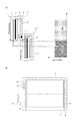
次に、図2(a)及び図2(b)を用いて、本発明の第1の実施形態について説明する。図2(a)は、図1の丸枠部分を拡大した断面模式図及びその領域での画像信号を示す概念図であり、図2(b)は第1の実施形態に係る第1の放射線撮像装置D1の平面模式図である。
(First embodiment)
Next, the first embodiment of the present invention will be described with reference to FIGS. 2 (a) and 2 (b). FIG. 2A is a schematic cross-sectional view in which a round frame portion in FIG. 1 is enlarged and a conceptual diagram showing an image signal in the region, and FIG. 2B is a first radiation according to the first embodiment. It is a plane schematic diagram of imaging device D1.
図2(a)に示すように、複数の放射線撮像装置D1及びD2はそれぞれ、放射線検出パネル2、フレキシブル回路基板8及び/又はプリント回路基板5に搭載された集積回路IC、及び、第1部材1及び第2部材6を含む筐体を含む。放射線検出パネル2は、2次元マトリクス状に配列された複数の画素を含む画素アレイを有して照射された放射線を画像信号に変換する。フレキシブル回路基板8及び/又はプリント回路基板5に搭載された集積回路ICは、放射線検出パネル2に電気的に接続されている。第1部材1及び第2部材6を含む筐体は、少なくとも放射線検出パネル2及び集積回路ICを内包する。
As shown in FIG. 2A, each of the plurality of radiation imaging devices D1 and D2 includes a radiation detection panel 2, an integrated circuit IC mounted on the
このような放射線撮像セットSの複数の放射線撮像装置のうちの少なくとも1つの放射線撮像装置の筐体は、他の放射線撮像装置と空間的に重なっている一部における領域の放射線透過率が、その領域とは異なる領域の放射線透過率に比べて高くされている。より具体的には、放射線撮像セットSの複数の放射線撮像装置のうちの第2の放射線撮像装置D2よりも放射線照射側に配置された第1の放射線撮像装置D1の筐体は、以下の構成を備える。その筐体は、放射線照射側から見て第2の放射線撮像装置D2に空間的に重なる第1の領域の放射線透過率が、第1の放射線撮像装置D1の集積回路ICと対向する第2の領域の放射線透過率に比べて高くなるように、第1部材1と第2部材6とを含む。このような構成により、第2の放射線撮像装置D2と空間的に重なる第1の放射線撮像装置D1の筐体での放射線吸収が抑制される。それにより、第2の放射線撮像装置D2で得られる画像信号のうち、第1の領域と空間的に重なる画素から得られる信号の低下が抑制され、第1の放射線撮像装置の筐体に起因して第2の放射線撮像装置から得られる画像に発生し得るアーチファクトが抑制される。 The housing of at least one radiation imaging device of the plurality of radiation imaging devices of such a radiation imaging set S has a radiation transmittance of a region in a part spatially overlapping with other radiation imaging devices. It is higher than the radiation transmittance of a region different from the region. More specifically, the casing of the first radiation imaging apparatus D1 disposed on the radiation irradiation side of the second radiation imaging apparatus D2 among the plurality of radiation imaging apparatuses of the radiation imaging set S has the following configuration. Is provided. The housing has a second region in which the radiation transmittance of the first region spatially overlapping the second radiation imaging apparatus D2 when viewed from the radiation irradiation side faces the integrated circuit IC of the first radiation imaging apparatus D1. The first member 1 and the second member 6 are included so as to be higher than the radiation transmittance of the region. With such a configuration, radiation absorption in the housing of the first radiation imaging apparatus D1 that spatially overlaps the second radiation imaging apparatus D2 is suppressed. This suppresses a decrease in the signal obtained from the pixels spatially overlapping the first region among the image signals obtained by the second radiation imaging apparatus D2, and is attributed to the casing of the first radiation imaging apparatus. Thus, artifacts that can occur in an image obtained from the second radiation imaging apparatus are suppressed.
以下に、第1の実施形態に係る各放射線撮像装置の具体例について、説明する。各放射線撮像装置D1、D2には、放射線照射側から、放射線検出パネル2、粘着材3、基台4、プリント回路基板5の順に積層された結合体が筐体に内包される。放射線検出パネル2が粘着材3によって基台4に結合されることにより、放射線検出パネル2は基台4によって支持される。プリント回路基板5は、基台4を挟んで放射線検出パネル2とは反対側に配置される。また、各放放射線撮像装置D1、D2の筺体は、第1部材1と第2部材6とを含む。第1部材1は、第2部材6に比べて放射線透過率の高い部材からなる。第1の領域を構成する第1部材1は、放射線入射方向からの放射線透過性がアルミ当量5mm以下の材料が好ましく使用され、たとえばCFRPが用いられる。なお、第1部材1のうち画素アレイと対向する領域にあっては、第1の領域における放射線透過性よりも高いことが望ましい。一方、筐体のうち集積回路ICと対向する第2の領域を構成する第2部材6は、第1部材1より剛性が高く且つ放射線透過率の低い材料が好ましく、アルミニウムやマグネシウムといった金属材料が用いられる。放射線検出パネル2は、放射線を捕捉可能な画素アレイと、該画素アレイの外周に辺縁部を有する。第2の放射線撮像装置D2は、その画素アレイが第1の放射線撮像装置D1の画素アレイと一部重なるように配置され、どのラインにおいても各放射線撮像装置D1、D2のいずれかの画素アレイが確実に画像情報を取得するように構成される。結合された放射線画像は、第1の放射線撮像装置D1の画像信号と、第2の放射線撮像装置D2の画像信号のうちの第1の放射線撮像装置D1で得られていない領域の画像信号とを合成して作成される。ここで、第1の放射線撮像装置D1の画素アレイ端から筺体の端部までのエリアは、第1の放射線撮像装置D1の構造物が第2の放射線撮像装置D2に写り込んでしまい、結合された放射線画像にアーチファクトが生じ得る。そこで、本実施形態においては、第1部材1が側壁部、および、背面部まで回り込んで、第2の放射線撮像装置D2に写り込む部分である第1の領域を構成する。これにより、当該箇所に第2部材6を用いた場合と比較して、当該領域における筺体による放射線吸収による放射線の減衰を抑制できる。放射線画像の出力低下が少なければ、たとえば事前に取得してある放射線画像の出力低下量の情報と合わせることで、当該領域の画像を補正処理して、画質を向上させることが可能である。第1部材1と第2部材6との結合は、第1の領域の外側でネジ7を用いて行うことで、ネジ7が結合された放射線画像に写り込むことの無い構成とする。
A specific example of each radiation imaging apparatus according to the first embodiment will be described below. In each of the radiation imaging apparatuses D1 and D2, a combined body in which the radiation detection panel 2, the
図2(b)に示すように、本実施形態の筐体は、略方形を有し、4辺のうちの1辺を第1部材1で構成するが、残りの3辺およびすべての角部は第2部材6で構成する。このような構成とすることで、角部からの落下強度や、装置全体の剛性の確保が可能となる。また、第1部材1としてCFRPを用いる場合は、賦形性が悪いために箱形状に形成することが困難であり、その点でも1辺だけをCFRPとすることは利点がある。筺体には、放射線撮像装置の電源スイッチ10、放射線撮像装置の状態を表示するLED等の表示部11、集積回路ICへの電源供給基台信号送受信を行うケーブル12と接続される接続部9が備えられている。これらは、第1の放射線撮像装置D1においては、第2の放射線撮像装置D2と空間的に重なる第1の領域を除く領域に配置される。本実施形態では、第2部材6に設けることで、結合された放射線画像にこれらの構造物が写り込むことを無いような構成となる。放射線検出パネル2には、プリント回路基板5と電気的に接続されたフレキシブル回路基板8が、互いに直交する2辺に電気的に接続される。第1の放射線撮像装置D1のフレキシブル回路基板8は、第2の放射線撮像装置D2と空間的に重なる第1の領域を除く領域に配置されることで、結合された放射線画像にフレキシブル回路基板8が写り込むことが無いような構成となる。また、上記のように筐体のうち第1の領域を除く領域は、設置時の向きの誤りを防ぐために外部から視認可能になっていることが好ましい。
As shown in FIG. 2B, the casing of the present embodiment has a substantially square shape, and one of the four sides is constituted by the first member 1, but the remaining three sides and all corners Is constituted by the second member 6. With such a configuration, it is possible to ensure the drop strength from the corner and the rigidity of the entire apparatus. Further, when CFRP is used as the first member 1, it is difficult to form a box shape because of poor shapeability, and it is advantageous to use only one side as CFRP. The housing includes a
(第2の実施形態)
次に、図3(a)及び図3(b)を用いて、第2の実施形態を説明する。図3(a)は、図1の丸枠部分を拡大した断面模式図及びその領域での画像信号を示す概念図であり、図3(b)は第2の実施形態に係る第1の放射線撮像装置D1の平面模式図である。なお、第1の実施形態と同じ構成には同じ符号を付与して詳細な説明は省略する。
(Second Embodiment)
Next, a second embodiment will be described with reference to FIGS. 3 (a) and 3 (b). FIG. 3A is a schematic cross-sectional view in which the round frame portion of FIG. 1 is enlarged and a conceptual diagram showing an image signal in the region, and FIG. 3B is a first radiation according to the second embodiment. It is a plane schematic diagram of imaging device D1. In addition, the same code | symbol is provided to the same structure as 1st Embodiment, and detailed description is abbreviate | omitted.
第1の実施形態では、第1の領域における筐体の側壁においては、第1部材1で構成されているが、筐体の外形の厚み分だけ第1部材1で放射線が吸収され、第1の領域の側壁を除く他の領域に比べて、側壁の部分だけ放射線の吸収量が著しく高くなってしまう。そこで、第2の実施形態では、図3(a)に示すように、第1の領域における第1の放射線撮像装置D1の筐体の外形の厚さが、第1の領域とは別の例えば第2の領域における第1の放射線撮像装置の筐体Dの外形の厚さに比べて薄くなるように、構成されている。特に、第1の領域における第1の放射線撮像装置D1の筐体の外形の厚さが、第1の領域において端部に向かって薄くなるように構成されることが好ましい。このように構成すると、第1の実施形態に比べて、第1部材1で構成される側壁の高さが小さくなり、筐体の側壁による放射線吸収に起因する放射線画像のアーチファクトが更に抑制され得る。 In the first embodiment, the side wall of the housing in the first region is configured by the first member 1, but radiation is absorbed by the first member 1 by the thickness of the outer shape of the housing, and the first Compared to other regions except the side wall of the region, the amount of absorbed radiation is remarkably increased only in the side wall portion. Therefore, in the second embodiment, as shown in FIG. 3A, the thickness of the outer shape of the housing of the first radiation imaging apparatus D1 in the first region is different from that in the first region, for example. The first region is configured to be thinner than the outer thickness of the casing D of the first radiation imaging apparatus in the second region. In particular, the thickness of the outer shape of the housing of the first radiation imaging apparatus D1 in the first region is preferably configured to become thinner toward the end portion in the first region. If comprised in this way, compared with 1st Embodiment, the height of the side wall comprised by the 1st member 1 will become small, and the artifact of the radiographic image resulting from the radiation absorption by the side wall of a housing | casing can further be suppressed. .
また、図3(b)に示すように、略矩形の筐体の4辺のうち、第1領域を含む3辺が第1部材1からなり、残りの1辺が第2部材6からなる。そして、第2部材6からなる筐体の1辺に、フレキシブル回路基板8(不図示)、電源スイッチ10、表示部11、接続部9が設けられている。このような構成であれば、筐体が放射線照射側から見て略長方形の形状を有する場合、短辺及び長辺のいずれも第1部材1で構成される。この構成になり、より縦長の領域で結合された放射線画像を得たい場合には、短辺を第1の領域として重ねあわせ、より横長の結合された放射線画像を得たい場合には、長辺を第1の領域として重ねあわせることができる。これにより、第2の実施形態は、第1の実施形態に比べて撮影の自由度が向上する。
Further, as shown in FIG. 3B, among the four sides of the substantially rectangular casing, three sides including the first region are made of the first member 1, and the remaining one side is made of the second member 6. A flexible circuit board 8 (not shown), a
(第3の実施形態)
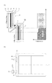
次に、図4(a)、図4(b)、及び図5を用いて、第3の実施形態を説明する。図4(a)は第3の実施形態に係る第1の放射線撮像装置D1の平面模式図であり、図4(b)は、図1の丸枠部分を拡大した断面模式図及びその領域での画像信号を示す概念図である。図5は、放射線撮像装置セットS内に放射線撮像装置を設置する設置部を説明する概念図である。なお、第1の実施形態と同じ構成には同じ符号を付与して詳細な説明は省略する。
(Third embodiment)
Next, the third embodiment will be described with reference to FIGS. 4A, 4B, and 5. FIG. 4A is a schematic plan view of the first radiation imaging apparatus D1 according to the third embodiment, and FIG. 4B is a schematic cross-sectional view in which the round frame portion of FIG. 1 is enlarged and its region. It is a conceptual diagram which shows the image signal of. FIG. 5 is a conceptual diagram illustrating an installation unit for installing the radiation imaging apparatus in the radiation imaging apparatus set S. In addition, the same code | symbol is provided to the same structure as 1st Embodiment, and detailed description is abbreviate | omitted.
第3の実施形態では、筺体が、略矩形の4辺のうちの1辺に開口を有する第3部材16と、第3部材16の開口を閉じることができる蓋部14と、蓋部14が開閉可能に第3部材16と接合する接合部15とを更に含む。放射線撮像装置を単体で使用する際には、蓋部14が閉じた形態で利用される。一方、放射線撮像装置の一部を重ねて結合された放射線画像を取得する長尺撮影を行う際には、蓋部14が開き筺体の1辺が開口している形態で利用され、筐体内の結合体が筺体外部に一部現れるように移動することができる。結合体に含まれる放射線検出パネル2の画素は、放射線を可視光に変換する蛍光体と、可視光を電気信号に変換する光電変換素子と、を含む構成が用いられ得る。そのため、放射線検出パネル2に光が当たると所望の放射線画像を得ることが出来ないので、蓋部14が開いた状態で放射線検出パネル2を遮光するための遮光部17が設けられる。この遮光部17は、実質的に筐体の一部を構成し、その放射線吸収率は第3部材16よりも低い材料を用いて構成されている。そして、蓋部14が開いた状態では、放射線検出パネル2及び遮光部17が、第2の放射線撮像装置D2と空間的に重なる位置に移動し得る。すなわち、放射線検出パネル2及び遮光部17が筐体の第1の領域となり、第1の放射線撮像装置の筐体に起因して第2の放射線撮像装置から得られる画像に発生し得るアーチファクトが抑制される。
In the third embodiment, the housing includes a
また、図5に示すように、蓋部14の端部には係止部18が設けられており、第3部材16に設けられた引掛け部19にて閉じた状態で固定されている。一方、放射線撮像装置セットSに設けられた設置部21には、ロック解除部20が設けられている。放射線撮像装置を放射線撮像装置セットSの設置部21に設置すると、ロック解除部20によって係止部18が押し上げられる。これにより、蓋部14の固定が解除され、蓋部14が図4(b)に示すような開いた状態となる。このような構成により、長尺撮影を行うために放射線撮像装置を放射線撮像装置セットSに設置した時には、長尺撮影のための形態に移行することが容易となる。
Further, as shown in FIG. 5, a locking
(第4の実施形態)
次に、図6を用いて第4の実施形態について説明する。図6は、図1の丸枠部分を拡大した断面模式図及びその領域での画像信号を示す概念図である。なお、第1の実施形態と同じ構成には同じ符号を付与して詳細な説明は省略する。
(Fourth embodiment)
Next, a fourth embodiment will be described with reference to FIG. FIG. 6 is a schematic cross-sectional view in which the round frame portion of FIG. In addition, the same code | symbol is provided to the same structure as 1st Embodiment, and detailed description is abbreviate | omitted.
複数の放射線撮像装置を収容する放射線撮像装置セットSの収容筐体には、被験者Mによる荷重から、収容されている放射線撮像装置や散乱線除去グリッド(不図示)を保護する保護板22が設けられている。この保護板22には、アクリルやポリカーボネードといった材料が用いられ得る。本実施形態では、この保護板22によって、放射線画像のアーチファクトが抑制されるように、保護板22の厚さに分布を持たせている。具体的には、第1領域に対応する領域での保護板22と第1の放射線撮像装置D1の筺体と放射線検出パネル2の辺縁部の3層の合算した放射線透過率が、第1領域以外の領域の保護板22分の放射線透過率と略同等となるようにする。これにより、第1の放射線撮像装置の筐体に起因して第2の放射線撮像装置から得られる画像に発生し得るアーチファクトが更に抑制される。
The housing case of the radiation imaging apparatus set S that houses a plurality of radiation imaging apparatuses is provided with a
M 被験者
R 放射線発生装置
S 放射線撮像装置セット
D1 第1の放射線撮像装置
D2 第2の放射線撮像装置
1 第1部材
2 放射線検出パネル
5 プリント回路基板
6 第2部材
8 フレキシブル回路基板
M subject R radiation generator S radiation imaging device set D1 first radiation imaging device D2 second radiation imaging device 1 first member 2 radiation detection panel 5 printed circuit board 6
Claims (10)
前記複数の放射線撮像装置は、第1の放射線撮像装置と第2の放射線撮像装置を含み、
前記第1の放射線撮像装置の筐体は、放射線照射側から見て前記第2の放射線撮像装置の放射線検出パネルの有効画素領域に空間的に重なる領域の放射線透過率が該空間的に重なる領域とは異なる領域の放射線透過率に比べて高い部分を含むことを特徴とする放射線撮像システム。 A plurality of radiation imaging apparatuses, each having a radiation detection panel that converts radiation irradiated with a plurality of pixels arranged in a two-dimensional matrix into an image signal, and a housing that contains the radiation detection panel, Radiation for acquiring radiation images based on respective image signals from the plurality of radiation imaging devices by arranging so that a part of effective pixel regions in each radiation detection panel is spatially overlapped when viewed from the radiation irradiation side In the imaging system,
The plurality of radiation imaging devices include a first radiation imaging device and a second radiation imaging device,
The housing of the first radiation imaging device is a region where the radiation transmittance of a region that spatially overlaps the effective pixel region of the radiation detection panel of the second radiation imaging device as viewed from the radiation irradiation side A radiation imaging system comprising a portion that is higher than the radiation transmittance of a different region .
前記複数の放射線撮像装置の夫々の筐体は、前記集積回路を更に内包し、
前記第1の放射線撮像装置の筐体は、前記放射線照射側から見て前記第2の放射線撮像装置の放射線検出パネルの有効画素領域に空間的に重なる第1の領域と、前記第1の放射線撮像装置の集積回路と対向する第2の領域とを備え、
前記第1の領域の放射線透過率が、前記第2の領域の放射線透過率に比べて高いことを特徴とする請求項1に記載の放射線撮像システム。 Each of the plurality of radiation imaging devices further includes an integrated circuit disposed on the back surface of the radiation detection panel and electrically connected to the radiation detection panel;
Each housing of the plurality of radiation imaging devices further includes the integrated circuit,
The housing of the first radiation imaging apparatus includes a first area spatially overlapping an effective pixel area of a radiation detection panel of the second radiation imaging apparatus as viewed from the radiation irradiation side, and the first radiation. A second region facing the integrated circuit of the imaging device,
The radiation imaging system according to claim 1, wherein a radiation transmittance of the first region is higher than a radiation transmittance of the second region.
前記放射線撮像装置の筐体は、放射線照射側から見て該放射線撮像装置とは異なる他の放射線撮像装置の放射線検出パネルの有効画素領域に空間的に重なる領域の放射線透過率が該空間的に重なる領域とは異なる領域の放射線透過率に比べて高い部分を含むことを特徴とする放射線撮像装置。 A plurality of radiation imaging apparatuses, each having a radiation detection panel that converts radiation irradiated with a plurality of pixels arranged in a two-dimensional matrix into an image signal, and a housing that contains the radiation detection panel, Radiation for acquiring radiation images based on respective image signals from the plurality of radiation imaging devices by arranging so that a part of effective pixel regions in each radiation detection panel is spatially overlapped when viewed from the radiation irradiation side In a radiation imaging apparatus used in an imaging system,
Wherein the housing of the radiation imaging apparatus, as viewed from the irradiation side the radiation imaging apparatus different from the radiation the radiation transmittance in the region overlapping in space and the effective pixel region of the radiation detection panel in the spatial imaging devices and A radiation imaging apparatus comprising a portion higher than the radiation transmittance of a region different from the overlapping region.
Priority Applications (13)
| Application Number | Priority Date | Filing Date | Title |
|---|---|---|---|
| JP2014246343A JP6071986B2 (en) | 2014-12-04 | 2014-12-04 | Radiation imaging system |
| CN201911223761.2A CN110833428B (en) | 2014-12-04 | 2015-11-27 | Radiation imaging system |
| PH12015000411A PH12015000411B1 (en) | 2014-12-04 | 2015-11-27 | Radiation imaging system |
| CN201510847728.2A CN105662442B (en) | 2014-12-04 | 2015-11-27 | radiation imaging system |
| RU2015151339A RU2637835C2 (en) | 2014-12-04 | 2015-11-30 | Beam imaging system |
| MYPI2015002861A MY178804A (en) | 2014-12-04 | 2015-12-02 | Radiation imaging system |
| SG10201509906YA SG10201509906YA (en) | 2014-12-04 | 2015-12-02 | Radiation imaging system |
| US14/957,031 US9801596B2 (en) | 2014-12-04 | 2015-12-02 | Radiation imaging system |
| GB1521257.4A GB2535590B (en) | 2014-12-04 | 2015-12-02 | Radiation imaging system |
| BR102015030401-3A BR102015030401B1 (en) | 2014-12-04 | 2015-12-03 | RADIATION IMAGE FORMATION SYSTEM |
| KR1020150171152A KR101927690B1 (en) | 2014-12-04 | 2015-12-03 | Radiation imaging system |
| DE102015121022.3A DE102015121022A1 (en) | 2014-12-04 | 2015-12-03 | Radiation imaging system |
| US15/718,710 US9974499B2 (en) | 2014-12-04 | 2017-09-28 | Radiation imaging system |
Applications Claiming Priority (1)
| Application Number | Priority Date | Filing Date | Title |
|---|---|---|---|
| JP2014246343A JP6071986B2 (en) | 2014-12-04 | 2014-12-04 | Radiation imaging system |
Related Child Applications (1)
| Application Number | Title | Priority Date | Filing Date |
|---|---|---|---|
| JP2016254377A Division JP6472432B2 (en) | 2016-12-27 | 2016-12-27 | Radiation imaging system |
Publications (3)
| Publication Number | Publication Date |
|---|---|
| JP2016106795A JP2016106795A (en) | 2016-06-20 |
| JP2016106795A5 JP2016106795A5 (en) | 2016-08-18 |
| JP6071986B2 true JP6071986B2 (en) | 2017-02-01 |
Family
ID=56121393
Family Applications (1)
| Application Number | Title | Priority Date | Filing Date |
|---|---|---|---|
| JP2014246343A Active JP6071986B2 (en) | 2014-12-04 | 2014-12-04 | Radiation imaging system |
Country Status (1)
| Country | Link |
|---|---|
| JP (1) | JP6071986B2 (en) |
Families Citing this family (1)
| Publication number | Priority date | Publication date | Assignee | Title |
|---|---|---|---|---|
| JP7091047B2 (en) * | 2017-10-06 | 2022-06-27 | キヤノン株式会社 | Radiation imaging system and radiography imaging method |
Family Cites Families (2)
| Publication number | Priority date | Publication date | Assignee | Title |
|---|---|---|---|---|
| US8038347B2 (en) * | 2007-12-21 | 2011-10-18 | General Electric Company | Portable tomographic diagnostic system with open gantry |
| JP2012040072A (en) * | 2010-08-16 | 2012-03-01 | Fujifilm Corp | Portable radiation image detector |
-
2014
- 2014-12-04 JP JP2014246343A patent/JP6071986B2/en active Active
Also Published As
| Publication number | Publication date |
|---|---|
| JP2016106795A (en) | 2016-06-20 |
Similar Documents
| Publication | Publication Date | Title |
|---|---|---|
| JP6611449B2 (en) | Radiation imaging system and radiation imaging system | |
| JP5675062B2 (en) | X-ray imaging device | |
| US9974499B2 (en) | Radiation imaging system | |
| US7745797B1 (en) | Digital x-ray detector assembly | |
| JP5642451B2 (en) | Portable radiography equipment set, portable radiography equipment | |
| JP6397208B2 (en) | Radiographic imaging apparatus and radiographic imaging system | |
| US8160207B2 (en) | Radiation imaging apparatus | |
| KR20160030454A (en) | Radiation imaging apparatus and radiation imaging system | |
| JP6472432B2 (en) | Radiation imaging system | |
| JP6525703B2 (en) | Radiography system, control method and program for radiography system | |
| JP6071986B2 (en) | Radiation imaging system | |
| JP6071985B2 (en) | Radiation imaging system | |
| JP6377101B2 (en) | Radiation detection apparatus and radiation detection system | |
| JP2004177250A (en) | Radiographic device | |
| JP2019069269A (en) | Radiation imaging system | |
| JP2017094131A5 (en) | ||
| JP7297826B2 (en) | Radiation imaging device and radiography system | |
| JP7346506B2 (en) | Radiation imaging device and radiography system | |
| CN115721326A (en) | Radiation imaging apparatus and radiation imaging system | |
| JP2021041030A (en) | Radiation detection device and radiographic device | |
| JP6072168B2 (en) | Radiation imaging system | |
| JP2023109151A (en) | Radiation imaging device and radiation imaging system | |
| JP2019066376A (en) | Radiation detection unit, radiation detection apparatus and radiation detection system | |
| JP2017200138A (en) | Radiation imaging device and radiation imaging system | |
| JP2017094009A (en) | Radiographic apparatus and radiographic system |
Legal Events
| Date | Code | Title | Description |
|---|---|---|---|
| A621 | Written request for application examination |
Free format text: JAPANESE INTERMEDIATE CODE: A621 Effective date: 20160519 |
|
| A521 | Request for written amendment filed |
Free format text: JAPANESE INTERMEDIATE CODE: A523 Effective date: 20160630 |
|
| A131 | Notification of reasons for refusal |
Free format text: JAPANESE INTERMEDIATE CODE: A131 Effective date: 20160823 |
|
| A521 | Request for written amendment filed |
Free format text: JAPANESE INTERMEDIATE CODE: A523 Effective date: 20160923 |
|
| TRDD | Decision of grant or rejection written | ||
| A01 | Written decision to grant a patent or to grant a registration (utility model) |
Free format text: JAPANESE INTERMEDIATE CODE: A01 Effective date: 20161206 |
|
| A61 | First payment of annual fees (during grant procedure) |
Free format text: JAPANESE INTERMEDIATE CODE: A61 Effective date: 20161227 |
|
| R151 | Written notification of patent or utility model registration |
Ref document number: 6071986 Country of ref document: JP Free format text: JAPANESE INTERMEDIATE CODE: R151 |