JP6071761B2 - Imaging apparatus and control method thereof - Google Patents
Imaging apparatus and control method thereof Download PDFInfo
- Publication number
- JP6071761B2 JP6071761B2 JP2013116245A JP2013116245A JP6071761B2 JP 6071761 B2 JP6071761 B2 JP 6071761B2 JP 2013116245 A JP2013116245 A JP 2013116245A JP 2013116245 A JP2013116245 A JP 2013116245A JP 6071761 B2 JP6071761 B2 JP 6071761B2
- Authority
- JP
- Japan
- Prior art keywords
- image
- signal
- photoelectric conversion
- imaging
- same subject
- Prior art date
- Legal status (The legal status is an assumption and is not a legal conclusion. Google has not performed a legal analysis and makes no representation as to the accuracy of the status listed.)
- Active
Links
Images


Classifications
-
- G—PHYSICS
- G02—OPTICS
- G02B—OPTICAL ELEMENTS, SYSTEMS OR APPARATUS
- G02B7/00—Mountings, adjusting means, or light-tight connections, for optical elements
- G02B7/28—Systems for automatic generation of focusing signals
- G02B7/34—Systems for automatic generation of focusing signals using different areas in a pupil plane
-
- H—ELECTRICITY
- H04—ELECTRIC COMMUNICATION TECHNIQUE
- H04N—PICTORIAL COMMUNICATION, e.g. TELEVISION
- H04N23/00—Cameras or camera modules comprising electronic image sensors; Control thereof
- H04N23/95—Computational photography systems, e.g. light-field imaging systems
- H04N23/958—Computational photography systems, e.g. light-field imaging systems for extended depth of field imaging
- H04N23/959—Computational photography systems, e.g. light-field imaging systems for extended depth of field imaging by adjusting depth of field during image capture, e.g. maximising or setting range based on scene characteristics
-
- H—ELECTRICITY
- H04—ELECTRIC COMMUNICATION TECHNIQUE
- H04N—PICTORIAL COMMUNICATION, e.g. TELEVISION
- H04N25/00—Circuitry of solid-state image sensors [SSIS]; Control thereof
- H04N25/10—Circuitry of solid-state image sensors [SSIS]; Control thereof for transforming different wavelengths into image signals
- H04N25/11—Arrangement of colour filter arrays [CFA]; Filter mosaics
- H04N25/13—Arrangement of colour filter arrays [CFA]; Filter mosaics characterised by the spectral characteristics of the filter elements
- H04N25/134—Arrangement of colour filter arrays [CFA]; Filter mosaics characterised by the spectral characteristics of the filter elements based on three different wavelength filter elements
-
- H—ELECTRICITY
- H04—ELECTRIC COMMUNICATION TECHNIQUE
- H04N—PICTORIAL COMMUNICATION, e.g. TELEVISION
- H04N25/00—Circuitry of solid-state image sensors [SSIS]; Control thereof
- H04N25/60—Noise processing, e.g. detecting, correcting, reducing or removing noise
- H04N25/61—Noise processing, e.g. detecting, correcting, reducing or removing noise the noise originating only from the lens unit, e.g. flare, shading, vignetting or "cos4"
-
- H—ELECTRICITY
- H04—ELECTRIC COMMUNICATION TECHNIQUE
- H04N—PICTORIAL COMMUNICATION, e.g. TELEVISION
- H04N25/00—Circuitry of solid-state image sensors [SSIS]; Control thereof
- H04N25/70—SSIS architectures; Circuits associated therewith
- H04N25/702—SSIS architectures characterised by non-identical, non-equidistant or non-planar pixel layout
Description
本発明は、瞳分割機能を有する撮像素子を用いる撮像装置に関し、特にシェーディングを良好に補正する技術に関するものである。 The present invention relates to an image pickup apparatus using an image pickup element having a pupil division function, and particularly to a technique for favorably correcting shading.
従来、1つの撮像光学系をリレーレンズを用いて瞳分割して2つの撮像素子で露光する撮像装置や、マイクロレンズ下の光電変換部を複数に分割して瞳分割像を得る方法が提案されている。それらは、得られた複数の画像の視差を利用して、ステレオ画像を得たり、位相差検出方式の自動焦点検出を行ったり、距離画像を作成したりといった用途に利用することができる。 Conventionally, an imaging apparatus that divides a pupil of one imaging optical system using a relay lens and exposes it with two imaging elements, and a method of obtaining a pupil-divided image by dividing a photoelectric conversion unit under a microlens into a plurality of parts have been proposed. ing. They can be used for applications such as obtaining a stereo image, performing auto focus detection using a phase difference detection method, or creating a distance image using the parallax of a plurality of obtained images.
距離画像を得たり、焦点検出を行う場合には瞳分割方向に2つの画像がどのくらいずれているのかを知る必要があり、SADやSSDといった相関演算を行う。相関演算では像の一致度の高い画像のずれ量をサーチするため、正しいずれ量における像の一致度が低いと正確なずれ量を検出することが困難となる。像の一致度が下がる要因としてシェーディングの違いがあげられる。したがって、シェーディングを良好に補正することが望まれている。 When obtaining a distance image or performing focus detection, it is necessary to know how many two images are in the pupil division direction, and a correlation calculation such as SAD or SSD is performed. In the correlation calculation, an image shift amount having a high image matching degree is searched. Therefore, if the image matching degree at a correct shift amount is low, it is difficult to detect an accurate shift amount. A difference in shading can be cited as a factor that reduces the degree of coincidence of images. Therefore, it is desired to correct shading well.
そのため、例えば特許文献1では相関演算で得られた像ずれ量に基づきA像とB像のレベル差を検出してシェーディングレベルを推定し、シェーディング補正係数を算出してシェーディング補正を行う技術が開示されている。特許文献2では、交換レンズから射出瞳の情報を得て、シェーディング補正係数を計算する技術が開示されている。 Therefore, for example, Patent Document 1 discloses a technique for detecting a level difference between an A image and a B image based on an image shift amount obtained by correlation calculation, estimating a shading level, calculating a shading correction coefficient, and performing shading correction. Has been. Patent Document 2 discloses a technique for obtaining exit pupil information from an interchangeable lens and calculating a shading correction coefficient.
しかしながら、上述の特許文献1に開示された技術では、前もって相関演算を行うため、最初の相関演算で間違った像ずれ量を検出するとシェーディング補正量を大きく間違えてしまい、間違っているにもかかわらず相関演算の信頼性が上がってしてしまう。 However, in the technique disclosed in Patent Document 1 described above, since the correlation calculation is performed in advance, if a wrong image shift amount is detected in the first correlation calculation, the shading correction amount is greatly mistaken, which is wrong. The reliability of the correlation calculation will increase.
また、上述の特許文献2に開示された技術では、幾何学的な計算をしなければならないので演算量が多くなり、計算に時間がかかりすぎてしまうという問題点がある。 Further, the technique disclosed in the above-mentioned Patent Document 2 has a problem in that the calculation amount increases because the geometric calculation must be performed, and the calculation takes too much time.
本発明は上述した課題に鑑みてなされたものであり、その目的は、事前に相関演算を行うことなく、少ない演算量によりシェーディング補正係数を算出することを可能にした撮像装置を提供することである。 The present invention has been made in view of the above-described problems, and an object thereof is to provide an imaging apparatus that can calculate a shading correction coefficient with a small amount of calculation without performing a correlation calculation in advance. is there.
本発明に係わる撮像装置は、撮像レンズの第1の瞳領域を通過した光を受光する第1の光電変換部と、前記第1の瞳領域とは重ならない前記撮像レンズの第2の瞳領域を通過した光を受光する第2の光電変換部とを有する画素が2次元状に配列された撮像素子と、前記撮像レンズに設けられたフォーカシングレンズの位置を光軸に沿ってずらしながら前記画素を露光させ、前記フォーカシングレンズの位置に応じて前記画素から得られる同一被写体の信号の撮像面上での像ずれ量を取得する取得手段と、前記フォーカシングレンズの位置に応じて前記画素から得られる同一被写体の信号のレベル比を検出する検出手段と、前記同一被写体の信号の撮像面上での像ずれ量と、前記同一被写体の信号のレベル比とに基づいてシェーディング補正係数を算出する算出手段と、を備えることを特徴とする。 An imaging apparatus according to the present invention includes a first photoelectric conversion unit that receives light that has passed through a first pupil region of an imaging lens, and a second pupil region of the imaging lens that does not overlap with the first pupil region. An image sensor in which pixels having a second photoelectric conversion unit that receives light passing through the two-dimensional array and a position of a focusing lens provided in the image pickup lens are shifted along the optical axis. Is obtained from the pixel according to the position of the focusing lens, and acquisition means for acquiring an image shift amount on the imaging surface of the signal of the same subject obtained from the pixel according to the position of the focusing lens. Based on the detection means for detecting the level ratio of the signal of the same subject, the amount of image shift on the imaging surface of the signal of the same subject, and the level ratio of the signal of the same subject. Characterized in that it comprises a calculation means for calculating.
本発明によれば、事前に相関演算を行うことなく、少ない演算量によりシェーディング補正係数を算出することを可能にした撮像装置を提供することが可能となる。 According to the present invention, it is possible to provide an imaging apparatus that can calculate a shading correction coefficient with a small amount of calculation without performing a correlation calculation in advance.
以下に、本発明の実施形態について、添付図面を参照して詳細に説明する。 Embodiments of the present invention will be described below in detail with reference to the accompanying drawings.
(第1の実施形態)
図1は、本発明の第1の実施形態の撮像装置の構成を示すブロック図である。また、図2は図1に示す撮像素子102の画素構造を示す図である。図2(a)は画素を上から見た図であり、図2(b)は画素の断面図である。図2において、201はマイクロレンズ、202および203は光電変換部である。通常の撮像素子ではマイクロレンズ1つに対して光電変換部が1つ配置されているが、第1の実施形態の撮像素子では光電変換部が2つに分割されており、それぞれ別の信号として読み出すことができる。図2の構造により瞳分割画像が得られる。
(First embodiment)
FIG. 1 is a block diagram showing a configuration of an imaging apparatus according to the first embodiment of the present invention. FIG. 2 is a diagram showing a pixel structure of the
図3はカラーフィルタの配列を示した図である。R(赤)、G(緑)、B(青)が2次元状に一定の繰り返し周期となって配置されたベイヤー配列と呼ばれる配列である。図3の配列とすることで光電変換部202,203の画素値を加算して得られる信号からカラー映像信号を作成することができる。本実施形態では、光電変換部202,203の信号を加算してカラー映像信号を作成する。
FIG. 3 is a diagram showing an arrangement of color filters. In this arrangement, R (red), G (green), and B (blue) are two-dimensionally arranged with a constant repetition period. With the arrangement shown in FIG. 3, a color video signal can be created from a signal obtained by adding the pixel values of the
次に図1を参照して第1の実施形態の撮像装置の全体構成について説明する。図1において、101は撮像レンズ、102は撮像素子、103はAD変換器、104はAB像分離器である。撮像素子から撮像レンズ101の第1の瞳領域を通過した光を受光する第1の光電変換部202と撮像レンズ101の第2の瞳領域を通過した光を受光する第2の光電変換部203の信号が交互に出力される。光電変換部202,203で2つに瞳分割された信号をそれぞれA像信号、B像信号として瞳領域ごとに分けるのがAB像分離器104の機能である。AB像分離器104の出力であるA像信号、B像信号はそれぞれシェーディング補正部106,107に入力され補正される。なお、B像信号については、シェーディング補正係数算出部108にも転送される。シェーディング補正係数算出部108からAゲイン像、Bゲイン像が出力され、シェーディング補正部106,107へ入力される。
Next, the overall configuration of the imaging apparatus according to the first embodiment will be described with reference to FIG. In FIG. 1, 101 is an imaging lens, 102 is an imaging device, 103 is an AD converter, and 104 is an AB image separator. A first
シェーディング補正部106,107で補正されたA像信号とB像信号は焦点検出部110と加算ベイヤー化部111へ入力される。加算ベイヤー化部111によってA像、B像が加算され、映像信号処理部112によって映像信号に変換される。映像信号処理部112の出力は表示や記録に利用されるが、表示や記録の詳細に関しては本発明の本質にかかわらない部分なので説明を省略する。マイクロコンピュータ109は撮像装置全体を制御する部分である。
The A image signal and the B image signal corrected by the
ここで図4を用いて瞳分割された像の特性について説明する。601はレンズであり、光電変換部202,203に分割して露光した信号は、それぞれ射出瞳602,603を通過した信号と等価な特性を持つ。射出瞳602,603を通過する光はピントが合っている面であるピント面605においては、被写体の一点から出射された光が再び一点に集まる。それの前後の面である604や606では、被写体の一点から出射された光がそれぞれ異なる位置に投影されることになる。被写体の同じ位置から出た光が射出瞳602,603を通過することで、投影位置がずれていればピントが合っていないことを意味するため、A像とB像のずれ量からデフォーカス量を算出することができる。
Here, the characteristics of an image obtained by pupil division will be described with reference to FIG.
図1の焦点検出部110では、A像とB像のずれ量を検出する。像のずれ量を検出する際にA像とB像にシェーディングによるレベル差があると像ずれ検出に誤差が生じたり、検出が失敗することがあるためシェーディングを補正しなければならない。
The
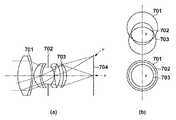
図5(a)のレンズ断面図を用いてシェーディングがなぜ起こるのかを説明する。図5において、701は前レンズ、702は絞り、703は後レンズである。前レンズ701の枠を前枠、後レンズ703によってできる枠を後枠と呼ぶ。704は撮像面である。撮像面704のxの位置から見た前レンズ701、絞り702、後レンズ703の枠の重なり方と、撮像面yの位置から見た前レンズ701、絞り702、後レンズ703の枠の重なり方を図5(b)に示している。xの位置から見ると光量を制限しているものは絞りだけであるが、yの位置から見ると前枠701と後枠703によっても光量が制限されている。
The reason why shading occurs will be described using the lens cross-sectional view of FIG. In FIG. 5,
図6は図5のyの位置における光が届く範囲と撮像素子の光電変換部を重ねたものである。光電変換部202と203では光が届く範囲が大きく異なることがわかる。このようにシェーディングとは光軸中心から離れて像高が高くなるにつれ光量が落ちてくる現象であり、瞳分割された像においては像高が高くなるとA像とB像のバランスがよりくずれるという性質がある。図6の斜線部の形状のことをケラレ形状といい、センサ上の画素位置との関係を図7に示す。ケラレ形状は場所により異なるが、場所がずれることにより少しずつ変化する。
FIG. 6 shows a range in which light reaches the position y in FIG. 5 and a photoelectric conversion unit of the image sensor. It can be seen that the range in which the light reaches the
図8(a)は横軸に撮像素子102上の位置、縦軸に光量を示した図であり、この形状がシェーディング像である。白い均一面を撮影すると図8(a)のようなシェーディング像と一致する像を得る事ができる。白い均一面を撮影しない限り、シェーディング像を得ることはできず、通常は、図8(b)のようにシェーディング像と被写体の像が重畳した映像信号が得られる。本実施形態では、シェーディング像と被写体の像が重畳した映像信号からシェーディング像を得て、シェーディング補正係数を得る。
FIG. 8A is a diagram in which the horizontal axis indicates the position on the
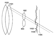
図9を用いて本実施形態の原理を説明する。図4においてピント面の説明をしたが、撮像面とピント面を一致させるために、一般に、フォーカシングレンズを移動させる。フォーカシングレンズを移動させることでピント面605を移動させて撮像素子102の面と一致させる。
The principle of this embodiment will be described with reference to FIG. Although the focus surface has been described with reference to FIG. 4, the focusing lens is generally moved in order to match the imaging surface and the focus surface. By moving the focusing lens, the
図9の1105は撮像素子の面である。フォーカシングレンズが1101の位置にあるときの瞳602を通過した像は撮像面上の1103の位置にある。それに対してフォーカシングレンズが1102の位置のときの像は1104の位置に移動する。すなわち、同じ被写体が撮像面状の異なる位置に投影された像を取得することができることを意味している。本実施形態ではフォーカシングレンズ位置の異なる複数の像を用いてシェーディング補正係数を求める。フォーカシングレンズの移動量に対する像の移動量は基線長により決まる一定量であるため、像がどこに移動したのかはレンズ移動量に一定の係数を掛けるだけで知ることができる。
1103、1104の図8(b)で901で示す部分を拡大したものが図10である。図10の1103と1104は異なるフォーカシングレンズ位置で露光された同一被写体の映像信号の一部を拡大したものである。それぞれの対応点を結ぶ線はシェーディングカーブ902と一致する。したがって、フォーカシング位置差で決まる横ずれ量を持った場所での同じ被写体の映像信号を比較すればシェーディングカーブを得ることができる。なお、シェーディングは透過率が低下するものなので、差分ではなくレベル比を求める必要がある。フォーカシングレンズを微少量動かすと像も微少量しか動かないが、そこで求めた比を連続的につないでいくことで全域のシェーディングカーブを得る事ができる。
FIG. 10 is an enlarged view of the portion denoted by
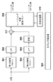
図11は図1のシェーディング補正係数算出部108の内部の詳細ブロック図である。シェーディング補正係数算出部108はマイクロコンピュータ109によって細かく制御され、内部回路の詳細な制御はタイミング発生器509によって行われている。
FIG. 11 is a detailed block diagram inside the shading correction
入力信号はB像のみであり、第1の画像メモリー501と第2の画像メモリー502には、フォーカシングレンズ位置の異なる時分割で露光されたB像が格納される。第1の画像、第2の画像ともにローパスフィルター503,504で高周波成分が取り除かれ、第2の画像のみ遅延回路506により所定量遅延される。遅延回路506の効果により比を求める除算器507に入力される像が横にずれることになる。遅延回路506で遅延される量は像の基線長で決まる。
The input signal is only the B image, and the
除算器507の出力は基線長できまるピッチの距離の画素との透過率の比である。シェーディング係数画像メモリー508は1画面分の補正係数を蓄積することができる。画面全域の補正係数を蓄積したら、正規化回路510により読み出し、像高中心を倍率1としたゲインに正規化して再びシェーディング係数画像メモリー508に書き戻す。以後は、撮像素子に連動した全体の同期信号に合わせたタイミングでAゲイン像、Bゲイン像が読みだされる。入力された第1の画像および第2の画像はB像のみなのでAゲイン像はBゲイン像の反転像となるようにメモリーをアドレッシングして生成される。
The output of the
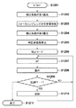
次にマイクロコンピュータ109による撮像装置全体の制御を図12のフローチャートを用いて説明する。
Next, control of the entire imaging apparatus by the
ステップS1201でシステムがスタートする。ステップS1202で補正係数用の第1露光が行われる。そして読み出されたB像信号が、第1の画像メモリー501に格納される。次にステップS1203でレンズ101が駆動されフォーカシングレンズが所定量移動する。ステップS1204で補正係数用の第2露光が行われる。読み出されたB像信号が第2の画像メモリー502に格納される。
In step S1201, the system starts. In step S1202, the first exposure for the correction coefficient is performed. The read B image signal is stored in the
ステップS1205で補正係数の算出が行われる。すなわち、第1の画像メモリー501、第2の画像メモリー502が読み出され、所定ピッチの比信号がシェーディング係数画像メモリー508に蓄積され、正規化回路510により読みだされる。そして、光軸中心を倍率1としたゲインに正規化されて再びシェーディング係数画像メモリー508に書き戻される。
In step S1205, a correction coefficient is calculated. That is, the
ステップS1206で補正モードに設定される。とAゲイン像、Bゲイン像が全体の同期信号に同期して出力される。ステップS1207でオートフォーカスを行う。このとき、A像およびB像はシェーディング補正部106,107によりシェーディング補正され、焦点検出部110に入力される。マイクロコンピュータ109は焦点検出部110の結果を読みとり、フォーカシングレンズを駆動して、ピントを合わせる。
In step S1206, the correction mode is set. A gain image and B gain image are output in synchronism with the entire synchronization signal. In step S1207, autofocus is performed. At this time, the A image and the B image are subjected to shading correction by the
ステップS1208で露光、ステップS1209で記録モードかどうかを判断してステップS1207に分岐するか、ステップ1210に分岐して記録するか、ステップ1211に分岐して終了するかが決定される。 In step S1208, it is determined whether the exposure mode is set, and in step S1209, whether the recording mode is selected, and it is determined whether the process branches to step S1207, branches to step 1210, records, or branches to step 1211.
マイクロコンピュータ109には図示していないが操作部材が接続されていて、ユーザーからの指示を知ることができる。このようにステップS1207からステップS1210を繰り返す事で、焦点検出をしながら画像を記録することができる。
Although not shown in the figure, an operating member is connected to the
(第2の実施形態)
以下、図13を参照して、本発明の第2の実施形態の撮像装置について説明する。図13は第2の実施形態における撮像素子の画素構造を示したものである。マイクロレンズ201に対応して光電変換部が1401,1402,1403,1404の4つに分割されている。これらの画素を用いて図13(c)の点線でグループ化しているように、光電変換部1401の信号と1403の信号を加算してA像とし、光電変換部1402と1404の信号を加算してB像とすることができる。
(Second Embodiment)
Hereinafter, an imaging apparatus according to the second embodiment of the present invention will be described with reference to FIG. FIG. 13 shows the pixel structure of the image sensor according to the second embodiment. Corresponding to the
また、図13(d)のように光電変換部1401と1402を加算してC像信号、光電変換部1403と1404を加算してD像信号とする。このように4つに分割することで縦に瞳分割した構成と横に瞳分割した構成の両方の信号を作り出すことができる。
Further, as shown in FIG. 13D, the
図14は第2の実施形態の撮像装置の構成を示すブロック図である。ABCD像加算分離部1501によって上記のA像B像C像D像を作り出す。A像、B像の扱いは第1の実施形態と同じである。新たにC像、D像で縦の瞳分割信号ができたので、新たなシェーディング補正係数算出部1504が追加されている。縦に像ずれするため、内部の遅延もラインごと遅延して縦ずれに対応している。そして焦点検出部110には縦に瞳分割された像と横に瞳分割された像が入力され、より多様な被写体においても焦点検出が可能となっている。
FIG. 14 is a block diagram illustrating a configuration of the imaging apparatus according to the second embodiment. The ACD B image C image D image is generated by the ABCD image addition /
以上、本発明の実施形態について説明したが、本発明はこれらの実施形態に限定されず、その要旨の範囲内で種々の変形及び変更が可能である。 As mentioned above, although embodiment of this invention was described, this invention is not limited to these embodiment, A various deformation | transformation and change are possible within the range of the summary.
例えば第1及び第2の実施形態において、1つのマイクロレンズに対して複数のフォトダイオードで瞳分割をした例を示したが、瞳分割されている信号であれば、マイクロレンズとフォトダイオードの間で遮光して瞳分割した信号でも同様の効果が得られる。 For example, in the first and second embodiments, an example in which a pupil is divided by a plurality of photodiodes with respect to one microlens has been described. The same effect can be obtained even if the signal is divided into pupils by shading.
また、第1及び第2の実施形態ではB像のシェーディング係数を反転させてA像のシェーディング係数としているが、別々に演算してもよい。 In the first and second embodiments, the shading coefficient for the B image is inverted to obtain the shading coefficient for the A image, but may be calculated separately.
また、第2の実施形態では横のシェーディング補正のみ行った信号を加算してベイヤー化しているが、縦と横のシェーディング係数の両方により補正した信号で加算ベイヤー化するほうがより良い映像信号となり望ましい。 In the second embodiment, a signal obtained by performing only horizontal shading correction is added to form a Bayer. However, it is preferable to perform addition Bayer using a signal corrected by both the vertical and horizontal shading coefficients, which is desirable. .
また、第1及び第2の実施形態において、単板撮像素子による画像を想定しているが、本発明の効果は2板、3板撮像素子においても同様に得られる。また瞳分割を行う位置ははマイクロレンズとフォトダイオードの間でなくてもよい。 In the first and second embodiments, an image by a single-plate image sensor is assumed. However, the effect of the present invention can be similarly obtained by a two-plate and three-plate image sensor. Further, the position for dividing the pupil may not be between the microlens and the photodiode.
図15にリレーレンズにおける平行光領域(物体側焦点位置の点光源から広がる光が平行になる領域)で、入射光を同時に左右の画像に分離し、A像B像を別の撮像素子を用いて露光するシステムの光学的構造を示す。1301はミラー、1302は絞り、1303はリレーレンズである。リレーレンズ1303により平行になった光をミラー1301により左右に分割する。分割された光はそれぞれミラー1305,1304で反射されて、結像レンズ1306,1307に導かれ、撮像素子1308,1309に結像される。このような構成とすることでA像とB像を同時に2つの撮像素子で得ることが可能となり、第1及び第2の実施形態と同様の効果が得られる。またA像とB像を時分割で露光してもよい。
FIG. 15 shows a parallel light region in the relay lens (a region where light spreading from the point light source at the object-side focal position becomes parallel), and simultaneously separates incident light into left and right images, and uses A and B images using different image sensors. The optical structure of the exposure system is shown. 1301 is a mirror, 1302 is a stop, and 1303 is a relay lens. The light collimated by the
Claims (5)
前記撮像レンズに設けられたフォーカシングレンズの位置を光軸に沿ってずらしながら前記画素を露光させ、前記フォーカシングレンズの位置に応じて前記画素から得られる同一被写体の信号の撮像面上での像ずれ量を取得する取得手段と、
前記フォーカシングレンズの位置に応じて前記画素から得られる同一被写体の信号のレベル比を検出する検出手段と、
前記同一被写体の信号の撮像面上での像ずれ量と、前記同一被写体の信号のレベル比とに基づいてシェーディング補正係数を算出する算出手段と、
を備えることを特徴とする撮像装置。 A first photoelectric conversion unit that receives light that has passed through the first pupil region of the imaging lens, and a first photoelectric unit that receives light that has passed through the second pupil region of the imaging lens that does not overlap the first pupil region. An image sensor in which pixels having two photoelectric conversion units are arranged in a two-dimensional manner;
The pixel is exposed while shifting the position of the focusing lens provided on the imaging lens along the optical axis, and the image shift on the imaging surface of the signal of the same subject obtained from the pixel according to the position of the focusing lens An acquisition means for acquiring an amount;
Detecting means for detecting a level ratio of signals of the same subject obtained from the pixels according to a position of the focusing lens;
Calculation means for calculating a shading correction coefficient based on an image shift amount on the imaging surface of the signal of the same subject and a level ratio of the signal of the same subject;
An imaging apparatus comprising:
前記撮像レンズに設けられたフォーカシングレンズの位置を光軸に沿ってずらしながら前記画素を露光させ、前記フォーカシングレンズの位置に応じて前記画素から得られる同一被写体の信号の撮像面上での像ずれ量を取得する取得工程と、
前記フォーカシングレンズの位置に応じて前記画素から得られる同一被写体の信号のレベル比を検出する検出工程と、
前記同一被写体の信号の撮像面上での像ずれ量と、前記同一被写体の信号のレベル比とに基づいてシェーディング補正係数を算出する算出工程と、
を有することを特徴とする撮像装置の制御方法。 A first photoelectric conversion unit that receives light that has passed through the first pupil region of the imaging lens, and a first photoelectric unit that receives light that has passed through the second pupil region of the imaging lens that does not overlap the first pupil region. A method of controlling an imaging device including an imaging device in which pixels having two photoelectric conversion units are arranged in a two-dimensional manner,
The pixel is exposed while shifting the position of the focusing lens provided on the imaging lens along the optical axis, and the image shift on the imaging surface of the signal of the same subject obtained from the pixel according to the position of the focusing lens An acquisition process for acquiring the quantity;
A detection step of detecting a level ratio of signals of the same subject obtained from the pixels according to the position of the focusing lens;
A calculation step of calculating a shading correction coefficient based on an image shift amount on the imaging surface of the signal of the same subject and a level ratio of the signal of the same subject;
A method for controlling an imaging apparatus, comprising:
Priority Applications (2)
| Application Number | Priority Date | Filing Date | Title |
|---|---|---|---|
| JP2013116245A JP6071761B2 (en) | 2013-05-31 | 2013-05-31 | Imaging apparatus and control method thereof |
| US14/292,101 US9578230B2 (en) | 2013-05-31 | 2014-05-30 | Image capturing apparatus that performs shading correction and control method therefor |
Applications Claiming Priority (1)
| Application Number | Priority Date | Filing Date | Title |
|---|---|---|---|
| JP2013116245A JP6071761B2 (en) | 2013-05-31 | 2013-05-31 | Imaging apparatus and control method thereof |
Publications (2)
| Publication Number | Publication Date |
|---|---|
| JP2014235287A JP2014235287A (en) | 2014-12-15 |
| JP6071761B2 true JP6071761B2 (en) | 2017-02-01 |
Family
ID=51984692
Family Applications (1)
| Application Number | Title | Priority Date | Filing Date |
|---|---|---|---|
| JP2013116245A Active JP6071761B2 (en) | 2013-05-31 | 2013-05-31 | Imaging apparatus and control method thereof |
Country Status (2)
| Country | Link |
|---|---|
| US (1) | US9578230B2 (en) |
| JP (1) | JP6071761B2 (en) |
Families Citing this family (3)
| Publication number | Priority date | Publication date | Assignee | Title |
|---|---|---|---|---|
| US9681038B2 (en) * | 2014-09-15 | 2017-06-13 | Lg Electronics Inc. | Mobile terminal and method for setting a focal point value |
| JP6504910B2 (en) * | 2015-05-19 | 2019-04-24 | キヤノン株式会社 | IMAGE PROCESSING APPARATUS, IMAGING APPARATUS, IMAGE PROCESSING METHOD, AND IMAGE PROCESSING PROGRAM |
| JP2017228913A (en) * | 2016-06-22 | 2017-12-28 | オリンパス株式会社 | Imaging apparatus |
Family Cites Families (9)
| Publication number | Priority date | Publication date | Assignee | Title |
|---|---|---|---|---|
| JP2715958B2 (en) * | 1995-03-03 | 1998-02-18 | 株式会社ニコン | Focus detection device |
| JP4265029B2 (en) | 1999-05-11 | 2009-05-20 | 株式会社ニコン | Image capturing device and interchangeable lens |
| JP2004012493A (en) * | 2002-06-03 | 2004-01-15 | Canon Inc | Focus detector |
| JP5089515B2 (en) * | 2008-07-15 | 2012-12-05 | キヤノン株式会社 | Focus adjustment device, imaging device, interchangeable lens, conversion coefficient calibration method, conversion coefficient calibration program |
| JP5237077B2 (en) * | 2008-12-16 | 2013-07-17 | キヤノン株式会社 | FOCUS DETECTION DEVICE, ITS CONTROL METHOD, AND PROGRAM |
| JP5737929B2 (en) * | 2010-12-22 | 2015-06-17 | キヤノン株式会社 | Image processing apparatus and image processing method |
| JP5685080B2 (en) * | 2010-12-28 | 2015-03-18 | キヤノン株式会社 | Focus detection apparatus and focus detection method |
| JP5956782B2 (en) * | 2011-05-26 | 2016-07-27 | キヤノン株式会社 | Imaging device and imaging apparatus |
| JP5979961B2 (en) * | 2012-05-07 | 2016-08-31 | キヤノン株式会社 | FOCUS DETECTION DEVICE, FOCUS DETECTION METHOD, AND IMAGING DEVICE |
-
2013
- 2013-05-31 JP JP2013116245A patent/JP6071761B2/en active Active
-
2014
- 2014-05-30 US US14/292,101 patent/US9578230B2/en active Active
Also Published As
| Publication number | Publication date |
|---|---|
| JP2014235287A (en) | 2014-12-15 |
| US20140354875A1 (en) | 2014-12-04 |
| US9578230B2 (en) | 2017-02-21 |
Similar Documents
| Publication | Publication Date | Title |
|---|---|---|
| JP5219865B2 (en) | Imaging apparatus and focus control method | |
| US9936122B2 (en) | Control apparatus, control method, and non-transitory computer-readable storage medium for performing focus control | |
| JP5448621B2 (en) | IMAGING DEVICE AND IMAGING DEVICE CONTROL METHOD | |
| US10530994B2 (en) | Image capture apparatus, control method for image capture apparatus and non-transitory recording medium for combining image | |
| US20140022359A1 (en) | Stereoscopic imaging apparatus and stereoscopic imaging method | |
| JP6014452B2 (en) | FOCUS DETECTION DEVICE, LENS DEVICE HAVING THE SAME, AND IMAGING DEVICE | |
| JP6029496B2 (en) | FOCUS DETECTION DEVICE, ITS CONTROL METHOD, IMAGING DEVICE, PROGRAM, AND STORAGE MEDIUM | |
| JP5737929B2 (en) | Image processing apparatus and image processing method | |
| US10362214B2 (en) | Control apparatus, image capturing apparatus, control method, and non-transitory computer-readable storage medium | |
| JP6071761B2 (en) | Imaging apparatus and control method thereof | |
| US10999491B2 (en) | Control apparatus, image capturing apparatus, control method, and storage medium | |
| JP2013097154A (en) | Distance measurement device, imaging apparatus, and distance measurement method | |
| US20190320122A1 (en) | Control apparatus, image capturing apparatus, control method, and non-transitory computer-readable storage medium | |
| US20200092489A1 (en) | Optical apparatus, control method, and non-transitory computer-readable storage medium | |
| JP2018185354A (en) | Controller, imaging device, control method, program, and storage medium | |
| JP2018010245A (en) | Signal processor and control method therefor | |
| KR101839357B1 (en) | Imaging apparatus and imaging method | |
| JP2012103285A (en) | Focus detecting device and method for controlling the same | |
| JP6000738B2 (en) | Imaging device and method of determining focusing direction of imaging device | |
| JP2019168494A (en) | Imaging device and control method therefor | |
| JP7019442B2 (en) | Image pickup device and its control method | |
| JP7346021B2 (en) | Image processing device, image processing method, imaging device, program and recording medium | |
| JP6541477B2 (en) | IMAGE PROCESSING APPARATUS, IMAGING APPARATUS, IMAGE PROCESSING METHOD, AND PROGRAM | |
| JP6456334B2 (en) | Imaging device | |
| JP6415139B2 (en) | Focus detection apparatus, imaging apparatus, focus detection method, and focus detection program |
Legal Events
| Date | Code | Title | Description |
|---|---|---|---|
| A621 | Written request for application examination |
Free format text: JAPANESE INTERMEDIATE CODE: A621 Effective date: 20160517 |
|
| TRDD | Decision of grant or rejection written | ||
| A01 | Written decision to grant a patent or to grant a registration (utility model) |
Free format text: JAPANESE INTERMEDIATE CODE: A01 Effective date: 20161205 |
|
| A61 | First payment of annual fees (during grant procedure) |
Free format text: JAPANESE INTERMEDIATE CODE: A61 Effective date: 20161227 |
|
| R151 | Written notification of patent or utility model registration |
Ref document number: 6071761 Country of ref document: JP Free format text: JAPANESE INTERMEDIATE CODE: R151 |