JP6071364B2 - Image processing apparatus, control method thereof, and control program - Google Patents
Image processing apparatus, control method thereof, and control program Download PDFInfo
- Publication number
- JP6071364B2 JP6071364B2 JP2012205585A JP2012205585A JP6071364B2 JP 6071364 B2 JP6071364 B2 JP 6071364B2 JP 2012205585 A JP2012205585 A JP 2012205585A JP 2012205585 A JP2012205585 A JP 2012205585A JP 6071364 B2 JP6071364 B2 JP 6071364B2
- Authority
- JP
- Japan
- Prior art keywords
- image
- image signal
- processing apparatus
- display
- signal
- Prior art date
- Legal status (The legal status is an assumption and is not a legal conclusion. Google has not performed a legal analysis and makes no representation as to the accuracy of the status listed.)
- Expired - Fee Related
Links
- 238000012545 processing Methods 0.000 title claims description 94
- 238000000034 method Methods 0.000 title claims description 68
- 238000006243 chemical reaction Methods 0.000 claims description 89
- 238000012937 correction Methods 0.000 claims description 56
- 230000008569 process Effects 0.000 claims description 31
- 230000009466 transformation Effects 0.000 claims description 31
- 238000003384 imaging method Methods 0.000 claims description 27
- 230000003287 optical effect Effects 0.000 claims description 20
- 238000000844 transformation Methods 0.000 claims description 6
- 230000006870 function Effects 0.000 description 10
- 239000004973 liquid crystal related substance Substances 0.000 description 10
- 238000003860 storage Methods 0.000 description 10
- 238000010586 diagram Methods 0.000 description 8
- 230000008859 change Effects 0.000 description 4
- 238000003702 image correction Methods 0.000 description 2
- 239000007787 solid Substances 0.000 description 2
- 241001442234 Cosa Species 0.000 description 1
- 244000089409 Erythrina poeppigiana Species 0.000 description 1
- 235000009776 Rathbunia alamosensis Nutrition 0.000 description 1
- 230000008901 benefit Effects 0.000 description 1
- 238000004590 computer program Methods 0.000 description 1
- 238000009826 distribution Methods 0.000 description 1
- 238000004519 manufacturing process Methods 0.000 description 1
- 238000005259 measurement Methods 0.000 description 1
- 230000002093 peripheral effect Effects 0.000 description 1
- 238000011160 research Methods 0.000 description 1
Images


Landscapes
- Processing Or Creating Images (AREA)
- Image Processing (AREA)
- Studio Devices (AREA)
Description
本発明は、撮像装置などで得られた画像を画像処理して補正する画像処理装置、制御方法、および制御プログラムに関する。 The present invention relates to an image processing apparatus, a control method, and a control program for correcting an image obtained by an image pickup apparatus by image processing.
一般に、魚眼光学系又は全方位光学系などに代表される超広視野光学系は、監視、遠隔操作、TV会議、医療用内視鏡、および科学的測量などの様々な分野で利用されている。超広視野光学系の特徴は、画角180度前後の超広視野像を特殊な射影方式によって撮像面の有限領域に投影可能な点にある。この特徴によって、一般的な中心射影(透視投影)方式で撮像する撮像装置などでは理論的に撮像できない超広視野像を撮像することができる。 In general, an ultra-wide-field optical system represented by a fish-eye optical system or an omnidirectional optical system is used in various fields such as surveillance, remote control, video conference, medical endoscope, and scientific surveying. Yes. The feature of the ultra-wide field optical system is that an ultra-wide field image with an angle of view of about 180 degrees can be projected onto a finite region of the imaging surface by a special projection method. With this feature, it is possible to capture an ultra-wide field image that cannot be theoretically captured by an imaging device that captures images using a general central projection (perspective projection) method.
ところが、超広視野像を撮像するため魚眼光学系などの特殊な射影方式による光学系では、撮像の結果得られた画像において不可避的に被写体像の形状が歪んでしまう。このため、当該画像を人間が観察する点を考慮すると、本来の被写体の形状と撮像の結果得られた画像における被写体像の形状との相違が著しく、被写体を正確に視認できないことがある。 However, in an optical system using a special projection method such as a fish-eye optical system for capturing an ultra-wide field image, the shape of the subject image is inevitably distorted in the image obtained as a result of imaging. For this reason, taking into consideration that the image is observed by a human, the difference between the original shape of the subject and the shape of the subject image in the image obtained as a result of imaging may be significant, and the subject may not be accurately recognized.
このような問題点を考慮しても、上記の特殊な射影方式には広範囲をカバーできるなどの目的および利用意図があり、特に、測量などの使用においては、歪みにみえる部分が光学的に正しい画像であることが望まれている。 Even if these problems are taken into account, the above-mentioned special projection method has a purpose and intended use such as covering a wide range, and particularly in the use of surveying, the part that appears to be distorted is optically correct. It is desired to be an image.
ここで、魚眼レンズなどの所謂超広視野光学系レンズにおける光学的な射影方式について概説する。 Here, an outline of an optical projection method in a so-called ultra-wide field optical system lens such as a fish-eye lens will be described.
魚眼レンズとは本来、180度前後の視野を感光面(撮像面)に射影可能な屈折レンズをいうが、ここでは反射鏡又はプリズムを用いて広視野を得る光学系も含めて魚眼レンズと呼ぶことにする。 A fish-eye lens is a refractive lens that can project a field of view around 180 degrees onto a photosensitive surface (imaging surface), but here it is referred to as a fish-eye lens including an optical system that obtains a wide field of view using a reflector or prism. To do.
厳密にいうと、魚眼レンズは広い画角によってではなく、その射影方式によって定義される。以下簡単にその射影方式の原理について説明する。 Strictly speaking, a fisheye lens is defined not by a wide angle of view but by its projection method. The principle of the projection method will be briefly described below.
図7は、魚眼レンズにおける射影方式の原理、特に、正射影方式の原理を説明するための図である。 FIG. 7 is a diagram for explaining the principle of the projection method in the fish-eye lens, particularly the principle of the orthographic projection method.
図7において、半球面Gは、魚眼レンズによって結像面(撮像面)上に結像される画像の範囲を直径とする仮想球面である。ここで、全ての射影方式において、画像の中心Oが半球面Gの天頂に相当する。そして画像内の一点P(これを像点と呼ぶ)に着目する。 In FIG. 7, a hemispherical surface G is a virtual spherical surface whose diameter is a range of an image formed on the imaging surface (imaging surface) by the fisheye lens. Here, the center O of the image corresponds to the zenith of the hemispherical surface G in all projection methods. Then, pay attention to one point P (referred to as an image point) in the image.
各射影方式における画像の中心Oから像点Pまでの距離(これを像高と呼ぶ)は、入射光の天頂角(入射角と呼ぶ)と特定の関係がある。ここで、像高をrp、そして、入射角をθとすると、(a)等距離射影方式(Equidistant Projection)では、式(1)に示すように、像高rpは入射角θに比例する。この等距離射影方式は一般的な魚眼レンズで多く用いられている。 The distance from the image center O to the image point P (referred to as image height) in each projection method has a specific relationship with the zenith angle (referred to as incident angle) of incident light. Here, assuming that the image height is rp and the incident angle is θ, (a) In the equidistant projection method, the image height rp is proportional to the incident angle θ as shown in Expression (1). This equidistant projection method is often used in general fisheye lenses.
rp∝θ (1)
(b)平射影方式(Stereographic Projection)では、式(2)に示すように、像高rpは入射角θの半角の正接に比例する。
rp∝θ (1)
(B) In the stereographic projection method, the image height rp is proportional to the tangent of the half angle of the incident angle θ as shown in the equation (2).
rp∝tan(θ/2) (2)
(c)等立体角射影方式(Equisolidangle Projection)では、式(3)に示すように、像高rpは入射角θの半角の正弦に比例する。
rp∝tan (θ / 2) (2)
(C) In the equisolid angle projection method, the image height rp is proportional to the half sine of the incident angle θ, as shown in Equation (3).
rp∝sin(θ/2) (3)
等立体角射影方式では、被写体がとる立体角とその像との面積が比例するという特徴があり、画像上の面積を測定すれば、被写体の面積比を正しく求めることができる。そして、この特徴を利用して、等立体角射影方式は全天の雲量測定および森林の植生分布などの測量で用いられる。
rp∝sin (θ / 2) (3)
The equal solid angle projection method is characterized in that the solid angle taken by the subject is proportional to the area of the image, and the area ratio of the subject can be obtained correctly by measuring the area on the image. By utilizing this feature, the isosceles angle projection method is used for surveying the amount of all-sky clouds and the distribution of forest vegetation.
(d)正射影方式(Orthographic Projection)では、式(4)に示すように、像高rpは入射角θの正弦に比例する。 (D) In the orthographic projection method, the image height rp is proportional to the sine of the incident angle θ as shown in the equation (4).
rp∝sin θ (4)
この正射影方式では、天球をそのまま結像面に射影したものに等しい。そして、画像に占める面光源の面積が撮像した場所における照度に比例という特徴があり、これよって、正射影方式は照度測定および建築照明などの学術研究用途に利用されることが多い。
rp∝sin θ (4)
This orthographic projection method is equivalent to a celestial sphere projected directly onto the image plane. The area of the surface light source occupying the image is proportional to the illuminance at the location where the image was taken. Therefore, the orthogonal projection method is often used for academic research applications such as illuminance measurement and architectural lighting.
なお、図7に示す例では、(d)正射影方式の射影原理が示されている。 In the example shown in FIG. 7, (d) the projection principle of the orthographic projection method is shown.
従来の歪曲補正と呼ばれる画像補正処理では、撮像の結果得られた画像を歪みのない中心射影画像に変換している。通常の光学レンズは中心射影方式で撮像されるように光学設計されているものの、このような光学レンズにおいても像高が大きい領域では、レンズの特性および製造誤差などの様々要因で歪みが残る場合がある。そして、歪曲補正はこの歪みを補正する処理である。 In a conventional image correction process called distortion correction, an image obtained as a result of imaging is converted into a central projection image without distortion. Although ordinary optical lenses are optically designed to be imaged by the central projection method, even in such optical lenses, distortion remains in areas where the image height is large due to various factors such as lens characteristics and manufacturing errors. There is. The distortion correction is a process for correcting this distortion.
ところで、歪曲補正を用いて、魚眼レンズによる撮像の結果得られた画像を補正することが行われている。つまり、魚眼レンズによる撮像の結果得られた歪みを有する画像を、歪曲補正して歪みのない画像を得ることが行われている。 By the way, correction of an image obtained as a result of imaging with a fisheye lens is performed using distortion correction. That is, distortion-corrected images obtained as a result of imaging with a fisheye lens are subjected to distortion correction to obtain an image without distortion.
例えば、等距離射影方式を用いた魚眼レンズで撮像の結果得られた画像を中心射影方式の画像に変換して、歪曲補正を行うようにしたものがある(特許文献1参照)。 For example, there is one in which distortion correction is performed by converting an image obtained as a result of imaging with a fish-eye lens using an equidistant projection method into an image of a central projection method (see Patent Document 1).
さらに、魚眼カメラで撮像の結果得られた画像を画像処理する際、画角の拡大率を場所により相違させた変化関数を用い、中心射影に変換して表示画面を生成して像点の天頂角と方位角を求めるようにしたものがある(特許文献2参照)。 Furthermore, when the image obtained as a result of imaging with a fisheye camera is image-processed, a display function is generated by converting it into a central projection using a change function in which the enlargement ratio of the angle of view differs depending on the location. There is one in which a zenith angle and an azimuth angle are obtained (see Patent Document 2).
特許文献2においては、魚眼レンズを用いて得られた画像データを中心射影方式で変換し、水平および垂直方向のいずれか1方向の補正の度合いが他の方向の補正度合いよりも大きくなるよう補正を行う。そして、補正が大きい方向に係る画像データの端部を使用せずに周辺部における物体を認識し易くしている。 In Patent Document 2, image data obtained using a fisheye lens is converted by a central projection method, and correction is performed so that the degree of correction in one of the horizontal and vertical directions is greater than the degree of correction in the other direction. Do. And it makes it easy to recognize the object in the peripheral part without using the edge part of the image data concerning the direction where correction is large.
魚眼レンズを用いて撮像を行った際には、前述のように、各射影方式によって画像が異なり、特に、像高の大きい部分および中心領域において被写体像などの形状が本来の被写体とは大きく異なる。 When imaging is performed using a fisheye lens, as described above, the image differs depending on each projection method, and in particular, the shape of the subject image or the like is greatly different from the original subject in a portion with a large image height and a central region.
図8は、魚眼レンズを用いた撮像の結果得られた撮像画像を説明するための図である。そして、図8(a)は魚眼レンズを用いた画像イメージを示す図であり、図8(b)は魚眼レンズによる撮像画像を中心射影に変換した際の画像イメージを示す図である。 FIG. 8 is a diagram for explaining a captured image obtained as a result of imaging using a fisheye lens. FIG. 8A is a diagram illustrating an image image using a fisheye lens, and FIG. 8B is a diagram illustrating an image image when a captured image obtained by the fisheye lens is converted into a central projection.
ここでは、図8(a)に示す画像イメージを、歪曲補正(中心射影変換)して図8(b)に示す画像イメージを得ている。図8に示すように、像高が大きな部分において、同心円の間隔が広がり、歪曲補正後の画像は元の画像に比べて横方向に大きくなって広がっていることが分かる。 Here, the image shown in FIG. 8A is obtained by performing distortion correction (center projective transformation) on the image shown in FIG. 8A. As shown in FIG. 8, it can be seen that concentric circles are widened at a portion where the image height is large, and the image after distortion correction is larger and wider in the horizontal direction than the original image.
上述のような射影方式を用いた変換は、例えば、ソフトウェアなどを用いて行われている。特に、視野角の広い魚眼レンズで撮像された画像を中心射影に変換すれば、視野の広い中心射影の画像を得ることが可能である。 The conversion using the projection method as described above is performed using, for example, software. In particular, if an image captured by a fisheye lens with a wide viewing angle is converted into a central projection, an image with a central projection with a wide field of view can be obtained.
一方、画像の補正については、一般的に画像においてその水平および垂直方向を調整する傾き補正があり、さらに、撮像の際のレンズに係る歪曲収差補正については、例えば、撮像距離などのパラメータを調整しつつ水平および垂直線の少なくとも一方に基づいて補正度合いを調整することが行われている。 On the other hand, for image correction, there is generally tilt correction that adjusts the horizontal and vertical directions in an image. Further, for distortion correction related to a lens at the time of imaging, for example, parameters such as imaging distance are adjusted. However, the correction degree is adjusted based on at least one of the horizontal and vertical lines.
ところが、水平および垂直線の少なくとも一方に応じて傾き補正および歪曲収差補正を行うと、魚眼レンズなどの超広視野光学系を用いて得られた画像については、その水平および垂直線の少なくとも一方そのものが歪んでいるため、傾き補正を精度よく行うことが難しい。 However, when tilt correction and distortion correction are performed in accordance with at least one of the horizontal and vertical lines, for an image obtained using an ultra-wide field optical system such as a fisheye lens, at least one of the horizontal and vertical lines itself Since it is distorted, it is difficult to perform tilt correction with high accuracy.
従って、本発明の目的は、魚眼レンズなどの超広視野光学系を用いて得られた歪みを有する画像について、傾き補正などの調整値を精度よく調整することのできる画像処理装置、その制御方法、および制御プログラムを提供することにある。 Therefore, an object of the present invention is to provide an image processing apparatus capable of accurately adjusting an adjustment value such as tilt correction for an image having distortion obtained using an ultra-wide field optical system such as a fisheye lens, a control method thereof, And providing a control program.
上記の目的を達成するため、本発明による画像処理装置は、歪みを有する第1の画像信号に画像処理を施す画像処理装置であって、前記第1の画像信号に対して前記歪みを抑制するための第1の幾何学的変換を施して第2の画像信号を得る第1の処理手段と、前記第2の画像信号および前記第1の画像信号に対して、ユーザによって入力された調整値に応じて、前記第1の幾何学的変換と異なる第2の幾何学的変換を施すことで、それぞれ第3の画像信号および第4の画像信号を得る第2の処理手段と、画像を表示する表示手段とを有し、前記表示手段は、前記第1の画像信号に基づく画像を第1の表示領域に表示するとともに、前記第2の画像信号に基づく画像を第2の表示領域に表示し、ユーザによって前記調整値が入力されると、前記第4の画像信号に基づく画像を前記第1の表示領域に表示するともに、前記第3の画像信号に基づく画像を前記第2の表示領域に表示することを特徴とする。 To achieve the above object, an image processing apparatus according to the present invention is an image processing apparatus which performs image processing on a first image signal having a distortion, suppressing the distortion relative to the first image signal First processing means for performing a first geometric transformation for obtaining a second image signal, and an adjustment value input by a user for the second image signal and the first image signal depending on, at the first geometric transformations and different second geometric transformation the facilities Succoth, and second processing means for obtaining a third image signal and fourth image signal of each image Display means for displaying , wherein the display means displays an image based on the first image signal in a first display area and an image based on the second image signal in a second display area. When the adjustment value is input by the user, Both displays an image based on the fourth image signal to the first display area, and displaying an image based on the third image signal on the second display area.
本発明による制御方法は、歪みを有する第1の画像信号に画像処理を施す画像処理装置の制御方法であって、前記第1の画像信号に対して前記歪みを抑制するための第1の幾何学的変換を施して第2の画像信号を得る第1の処理ステップと、前記第2の画像信号および前記第1の画像信号に対して、ユーザによって入力された調整値に応じて、前記第1の幾何学的変換と異なる第2の幾何学的変換を施すことで、それぞれ第3の画像信号および第4の画像信号を得る第2の処理ステップと、画像を表示する表示ステップとを有し、前記表示手ステップでは、前記第1の画像信号に基づく画像を第1の表示領域に表示するとともに、前記第2の画像信号に基づく画像を第2の表示領域に表示し、ユーザによって前記調整値が入力されると、前記第4の画像信号に基づく画像を前記第1の表示領域に表示するともに、前記第3の画像信号に基づく画像を前記第2の表示領域に表示することを特徴とする。 Control method according to the present invention is a method of controlling an image processing apparatus for performing image processing on a first image signal having a distortion, a first geometry for suppressing the distortion relative to the first image signal A first processing step of performing a geometric conversion to obtain a second image signal, and the second image signal and the first image signal in accordance with an adjustment value input by a user, 1 geometrical transformations and different second geometric transformation the facilities Succoth, a second processing step for obtaining a third image signal and fourth image signal, respectively, and a display step of displaying an image And in the display step, the image based on the first image signal is displayed in the first display area, and the image based on the second image signal is displayed in the second display area. When the adjustment value is input, Both displays an image based on the fourth image signal to the first display area, and displaying an image based on the third image signal on the second display area.
本発明による制御プログラムは、歪みを有する第1の画像信号に画像処理を施す画像処理装置で用いられる制御プログラムであって、前記画像処理装置が備えるコンピュータに、前記第1の画像信号に対して前記歪みを抑制するための第1の幾何学的変換を施して第2の画像信号を得る第1の処理ステップと、前記第2の画像信号および前記第1の画像信号に対して、ユーザによって入力された調整値に応じて、前記第1の幾何学的変換と異なる第2の幾何学的変換を施すことで、それぞれ第3の画像信号および第4の画像信号を得る第2の処理ステップと、画像を表示する表示ステップとを実行させ、前記表示手ステップでは、前記第1の画像信号に基づく画像を第1の表示領域に表示するとともに、前記第2の画像信号に基づく画像を第2の表示領域に表示し、ユーザによって前記調整値が入力されると、前記第4の画像信号に基づく画像を前記第1の表示領域に表示するともに、前記第3の画像信号に基づく画像を前記第2の表示領域に表示することを特徴とする。 A control program according to the present invention is a control program used in an image processing apparatus that performs image processing on a first image signal having distortion, and the computer included in the image processing apparatus applies the first image signal to the computer program. A first processing step of obtaining a second image signal by performing a first geometric transformation for suppressing the distortion, and the user processing the second image signal and the first image signal by a user according to the input adjustment value, the first geometric transformations and different second geometric transformation the facilities Succoth, second processing, respectively obtain a third image signal and fourth image signal And a display step for displaying an image. In the display step, an image based on the first image signal is displayed in a first display area, and an image based on the second image signal is displayed. First When the adjustment value is input by the user, an image based on the fourth image signal is displayed on the first display area, and an image based on the third image signal is displayed on the display area. It displays on the 2nd display area, It is characterized by the above-mentioned .
本発明によれば、魚眼レンズなどの超広視野光学系を用いて得られた歪みを有する画像について、傾き補正などの調整を行う調整値を精度よく調整することができる。 ADVANTAGE OF THE INVENTION According to this invention, the adjustment value which performs adjustments, such as inclination correction | amendment, can be accurately adjusted about the image which has the distortion obtained using super-wide-field optical systems, such as a fisheye lens.
以下、本発明の実施の形態による画像処理装置の一例について図面を参照して説明する。 Hereinafter, an example of an image processing apparatus according to an embodiment of the present invention will be described with reference to the drawings.
[第1の実施形態]
図1は、本発明の第1の実施形態による画像処理装置の一例を示すブロック図である。なお、図示の画像処理装置は、例えば、デジタルカメラなどの撮像装置に備えられており、この撮像装置には撮像レンズ系として魚眼レンズなどの超広視野光学系が用いられている。
[First Embodiment]
FIG. 1 is a block diagram showing an example of an image processing apparatus according to the first embodiment of the present invention. Note that the illustrated image processing apparatus is provided in an imaging apparatus such as a digital camera, for example, and an ultra-wide field optical system such as a fish-eye lens is used as the imaging lens system in the imaging apparatus.
画像処理装置はCPUなどの画像処理制御部を有しており、この画像処理制御部は第1変換部101、第2変換部102、および記憶制御部104を備えている。そして、第1変換部101および第2変換部102は、表示部(液晶ディスプレイ)103に接続されている。
The image processing apparatus includes an image processing control unit such as a CPU. The image processing control unit includes a
なお、図示はしないが、撮像装置においては、魚眼レンズを介して入射した光学像がCMOSイメージセンサなどの撮像素子に結像する。そして、撮像素子は光学像に応じたアナログ信号を出力する。このアナログ信号はA/D変換器でデジタル信号(第1の画像信号)に変換されて、第1変換部101に与えられる。
Although not shown, in the imaging apparatus, an optical image incident through the fisheye lens is formed on an imaging element such as a CMOS image sensor. Then, the imaging element outputs an analog signal corresponding to the optical image. This analog signal is converted into a digital signal (first image signal) by an A / D converter, and is supplied to the
第1変換部101は、第1の画像信号における歪みを抑制するため、第1の幾何学的変換を施して第2の画像信号を生成する。なお、第1の幾何学的変換は、例えば、中心射影変換である。
The
上記の第2の画像信号は第2変換部102に与えられる。また、第2変換部102には、第1の画像信号が入力される。第2変換部102は第2の画像信号に対して、第1の幾何学的変換と異なる第2の幾何学的変換を施して第3の画像信号とする。さらに、第2変換部102は第1の画像信号に対して第2の幾何学的変換を施して第4の画像信号とする。
The second image signal is supplied to the
なお、第2の幾何学的変換は、例えば、傾き補正であり、この傾き補正は、ユーザが操作部から入力する調整値である回転角度に応じて行われる。 The second geometric transformation is, for example, inclination correction, and this inclination correction is performed according to a rotation angle that is an adjustment value input by the user from the operation unit.
第2変換部102で生成された第3の画像信号は表示部103に与えられ、表示部103には後述するように第3の画像信号に応じた画像がプレビュー画像として表示される。また、第2の変換部102で生成された第4の画像信号は表示部103に与えられ、表示部103には第4の画像信号に応じた画像(傾き補正画像)が表示される。
The third image signal generated by the
記憶制御部104には第2変換部102から第4の画像信号が与えられる。記憶制御部104はこの第4の画像信号を記憶媒体(図示せず)に画像データとして記憶する。
The
図2は、図1に示す画像処理装置における画像処理を説明するためのフローチャートである。 FIG. 2 is a flowchart for explaining image processing in the image processing apparatus shown in FIG.
画像処理が開始されると、画像処理装置は第1の画像信号を読み込む。そして、画像処理装置は図示しないメモリに格納された処理パラメータ(以下単にパラメータと呼ぶ)を読み込む(ステップS201)。ここで、パラメータとは、魚眼レンズに係るレンズ情報およびユーザが操作部(図示せず)から入力する画像調整用の調整値(例えば、回転角度)などである。 When the image processing is started, the image processing apparatus reads the first image signal. Then, the image processing apparatus reads processing parameters (hereinafter simply referred to as parameters) stored in a memory (not shown) (step S201). Here, the parameters are lens information related to the fisheye lens, adjustment values for image adjustment (for example, rotation angle) input by the user from an operation unit (not shown), and the like.
第2変換部102はパラメータに応じて傾き補正などの画像処理を行う。ユーザは表示部103に表示された画像を見て必要に応じて画像を調整するための調整値を入力する。ユーザは調整が完了すると、操作部から調整完了を示す調整完了操作を行う。
The
ここでは、まず、第2変換部102は調整値に応じて第1の画像信号に対して、例えば、回転処理を行って傾き補正を行い、第4の画像信号を生成して傾き補正画像を表示部103に表示する(ステップS202)。
Here, first, the
回転処理に当たっては、後述のように、ユーザは操作部から、調整値として通常角度を指定することができる。この通常角度の指定において刃最大0度から360度まで指定することができる。 In the rotation process, as will be described later, the user can specify a normal angle as an adjustment value from the operation unit. In the designation of the normal angle, the blade can be designated from 0 degrees to 360 degrees at the maximum.
第2変換部102は指定された角度に基づいて、各座標(x,y)を回転中心からの位置関係と三角関数をベースとするアルゴリズムによって座標変換して回転後の座標(X,Y)を得る。このアルゴリズムは、例えば、次の式(1)および(2)で示される。
Based on the specified angle, the
X=cosA*x+sinA*y (1)
Y=−sinA*x+cosA*y (2)
但し、回転中心を原点として、回転前座標を(x,y)、回転後座標を(X,Y)、回転角度をラジアン単位でAとする。
X = cosA * x + sinA * y (1)
Y = −sin A * x + cos A * y (2)
However, with the rotation center as the origin, the coordinates before rotation are (x, y), the coordinates after rotation are (X, Y), and the rotation angle is A in radians.
一方、第1変換部101は中心射影変換によって第1の画像信号における歪みを正確に又は簡易的に修正して、第2の画像信号を出力する。そして、第2変換部102は第2の画像信号に対して調整値に応じて傾き補正(つまり、回転処理)を行って、第3の画像信号とする。この第3の画像信号はプレビュー画像として表示部103に表示される(ステップS203)。
On the other hand, the
画像の歪みを補正する際には、例えば、第1変換部101はその中心からの距離(厳密には光学的な中心)をキーとして、予めメモリに格納された補正テーブルを参照して、歪みを補正するため元の画像の各点が変換後いずれに射影されるかを算出する。
When correcting the distortion of the image, for example, the
例えば、中心を原点とした際、座標(300,400)、原点からの距離が500である。この点を補正テーブルによって、例えば、距離600に射影すると、第1変換部101は距離600となる座標を変換後の座標とする。そして、当該変換を全ての点で行って補間を行えば、回転後(変換後)の全ての座標を求めることができる。
For example, when the center is the origin, the coordinates (300, 400) and the distance from the origin are 500. When this point is projected onto the distance 600 by using the correction table, for example, the
このようにして、元の画像と歪み補正後の画像において、各点の対応関係を決定することができる。この際、元の画像上の点は離散的に保持されているので、ある点の画素値が回転後の画像の点の画素値に対応できない場合には、当該点に関して周辺の点の画素値を用いて補間を行う。 In this way, the correspondence between points can be determined in the original image and the image after distortion correction. At this time, since the points on the original image are held discretely, if the pixel value of a certain point cannot correspond to the pixel value of the point of the rotated image, the pixel values of the surrounding points with respect to the point Interpolate using.
これによって、第1変換部101は歪み補正を行った画像(第2の画像信号)を求めることができる。
Accordingly, the
続いて、画像処理装置はユーザが調整完了操作を行ったか否かを判定する(ステップS204)。調整完了操作が行われないと(ステップS204において、NO)、つまり、ユーザが調整値の変更を行うと、画像処理装置101はステップS201に戻って、パラメータ、つまり、変更後の調整値を取得して、変更後の調整値に応じてステップS202の処理を行う。このようにして、ユーザが調整値を変更する都度、上記の処理が行われることになる。
Subsequently, the image processing apparatus determines whether or not the user has performed an adjustment completion operation (step S204). If the adjustment completion operation is not performed (NO in step S204), that is, if the user changes the adjustment value, the
一方、調整完了操作が行われると(ステップS204において、YES)、第2変換部102は調整完了後の調整値に応じて回転後の画像(傾き補正画像:第4の画像信号)を生成する(ステップS205)。そして、記憶制御部104は当該傾き補正画像を記録媒体に記憶して(ステップS206)、画像処理を終了する。なお、この際、歪みの修正は行われない。
On the other hand, when the adjustment completion operation is performed (YES in step S204), the
図3は、図1に示す第1変換部101で行われる画像の歪みの補正処理を説明するためのフローチャートである。なお、ここでは、等立体角射影の魚眼レンズで撮像の結果得られた画像について、射影方式を中心射影に変換して歪みを補正する。
FIG. 3 is a flowchart for explaining image distortion correction processing performed by the
歪み補正処理が開始されると、第1変換部101は魚眼レンズを用いて撮像された画像信号(以下単に画像ともいう)を入力する(ステップS501)。そして、第1変換部101はメモリから魚眼レンズに係るレンズ情報など必要なパラメータを取得する(ステップS502)。
When the distortion correction process is started, the
次に、第1変換部101は入力した画像において予め規定された複数の点(座標、つまり、画素)における1つの画素について画素値を取得する(ステップS503)。そして、第1変換部101は当該画素を射影変換して変換後の座標を得る(ステップS504)。
Next, the
続いて、第1変換部101は変換後の座標(つまり、画像)における画素値を画素補間によって算出する(ステップS505)。そして、第1変換部101は予め規定された座標(つまり、必要な画素)の全てについて変換処理を行ったか否かを判定する(ステップS506)。
Subsequently, the
全ての画素について変換処理を行っていないと(ステップS506において、NO)、第1変換部101はステップS503の処理に戻る。一方、全ての画素について変換処理が完了すると(ステップS506において、YES)、第1変換部101は変換処理後の画像を生成する(ステップS507)。そして、第1変換部101は歪み補正処理を終了する。
If the conversion process has not been performed for all pixels (NO in step S506), the
図4は、図1に示す第2変換部102で行われる回転処理を説明するためのフローチャートである。
FIG. 4 is a flowchart for explaining the rotation processing performed by the
回転処理を開始すると、第2変換部102はA/D変換器から第1の画像信号を入力するとともに、第1変換部101から第2の画像信号を入力する(ステップS601)。続いて、第2変換部102は変更後の調整値である回転角度を、メモリから取得する(ステップS602)。
When the rotation process is started, the
次に、第2変換部102は入力した画像(ここでは、第1および第2の画像信号である)において予め規定された複数の画素の1つを取得する(ステップS603)。そして、第2変換部102は、回転角度に応じて当該画素を回転処理して回転後の画素を求める(ステップS604)。
Next, the
続いて、第2変換部102は予め規定された座標(つまり、必要な画素)の全てについて回転処理を行ったか否かを判定する(ステップS605)。必要な画素の全てついて回転処理が行われていないと(ステップS605において、NO)、第2変換部102はステップS603の処理に戻って次の画素について回転処理を行う。
Subsequently, the
一方、必要な画素の全てついて回転処理を行うと(ステップS605において、YES)、第2変換部102は回転処理を終了して、回転処理後の画像を表示部103に表示する。つまり、ここでは、第2変換部102は第3の画像信号および第4の画像信号に応じた画像をそれぞれ表示部103に表示することになる。
On the other hand, when the rotation process is performed for all necessary pixels (YES in step S605), the
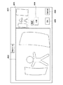
図5は、図1に示す画像処理装置における処理画像表示の一例を説明するための図である。なお、図5に示す例は、画像の調整を行う際にユーザが操作するユーザインタフェースであり、当該ユーザインタフェースは画像の回転処理を行うためのものであり、画像処理装置で動作するソフトウェアによって行われる。 FIG. 5 is a diagram for explaining an example of a processed image display in the image processing apparatus shown in FIG. Note that the example shown in FIG. 5 is a user interface operated by a user when adjusting an image. The user interface is for performing image rotation processing, and is executed by software operating on the image processing apparatus. Is called.
画像処理装置401の背面には表示部103である液晶ディスプレイ(表示領域)402が配置されるとともに、表示部103であるプレビュー用ディスプレイ(表示領域)403が配置されている。
A liquid crystal display (display area) 402 that is the
いま、ユーザが操作部によって調整値として角度入力欄404に角度0度を入力すると、第2変換部102は回転処理を行わずに、A/D変換器を介して読み込んだ第1の画像信号(つまり、回転処理が施されていない第4の画像信号)に応じた画像を液晶ディスプレイ402に表示することになる。
Now, when the user inputs an angle of 0 degrees into the
この際、第1変換部101は、図2で説明したようにして、第1の画像信号を中心射影変換して第2の画像信号を生成し、第2の画像信号を第2変換部102に与える。
At this time, as described with reference to FIG. 2, the
第2の変換部101は角度0度であるから、第2の画像信号に回転処理を施すことなく第4の画像信号を表示部103に与える。これによって、水平および垂直方向が見やすくなったプレビュー画像が、プレビュー用液晶ディスプレイ403に表示される。
Since the
ユーザは液晶ディスプレイ402および403に表示された画像を確認して、調整値(つまり、回転角度)を変更するか否かを決定することになる。ユーザがOKボタン405を押し下げると、画像処理装置は前述の調整完了操作があったと判定することになる。
The user checks the images displayed on the
一方、ユーザは調整値(つまり、回転角度)を変更する際には、キャンセル(Cancel)ボタン406を押し下げた後、操作部によって角度入力欄404に変更後の回転角度を入力する。これによって、画像処理装置は前述の調整完了操作が行われず、回転角度が変更されたと判定する。
On the other hand, when changing the adjustment value (that is, the rotation angle), the user depresses the Cancel
図6は、図1に示す画像処理装置における処理画像表示の他の例を説明するための図である。 FIG. 6 is a diagram for explaining another example of the processed image display in the image processing apparatus shown in FIG.
いま、ユーザがキャンセルボタン406を押し下げた後、操作部によって角度入力欄404に回転角度5度を入力したとする(つまり、回転角度を5度に変更したとする)。これによって、第2変換部102は変更後の回転角度5度に応じて第1の画像信号および第2の画像信号に対して回転処理を行って、それぞれ第3の画像信号および第4の画像信号を生成する。
Now, assume that after the user presses the cancel
そして、第2変換部102は第3の画像信号に応じたプレビュー画像(水平および垂直方向が見やすくなったプレビュー画像)を、プレビュー用液晶ディスプレイ403に表示する。また、第2変換部102は第4の画像信号に応じた画像(傾き補正画像)を、液晶ディスプレイ402に表示する。
Then, the
このようにして、ユーザは液晶ディスプレイ402および403に表示された画像を確認して、所望の画像が表示されるまで回転角度を変更することができる。そして、ユーザがOKボタン405を押し下げると、その時点で、第2変換部102で上述の処理が行われて、結果的に液晶ディスプレイ402に表示されている回転処理後の画像が記憶制御部104によって記憶媒体に記憶されることになる。
In this way, the user can check the images displayed on the
なお、記憶媒体は画像処理装置に内蔵するようにしてもよく、画像処理装置に接続された外部メモリであってもよい。 The storage medium may be built in the image processing apparatus or may be an external memory connected to the image processing apparatus.
このようにして、本発明の実施の形態では、中心射影変換処理された画像をプレビュー表示して、ユーザは当該プレビュー画像を確認して、画像の調整値である回転角度を変更する。これによって、ユーザは水平および垂直方向が見やすくなったプレビュー画像に対応する回転角度変更後の画像を、魚眼レンズの歪みをそのままとして記憶することができる。つまり、ユーザは魚眼レンズの歪みをそのままとして画像の傾きを容易に調整することができる。 In this way, in the embodiment of the present invention, the image subjected to the central projective transformation process is displayed as a preview, and the user confirms the preview image and changes the rotation angle that is the adjustment value of the image. Thus, the user can store the image after the rotation angle change corresponding to the preview image in which the horizontal and vertical directions are easy to see, with the distortion of the fisheye lens as it is. That is, the user can easily adjust the inclination of the image while keeping the distortion of the fisheye lens as it is.
以上のように、本実施の形態では、ユーザはプレビュー画像の水平および垂直方向の少なくとも一方を参照しつつ回転角度を調整するようにすれば、魚眼レンズで撮像された画像に対して、精度よく傾き補正を行うことができる。 As described above, in this embodiment, if the user adjusts the rotation angle while referring to at least one of the horizontal and vertical directions of the preview image, the user can accurately tilt the image captured by the fisheye lens. Correction can be performed.
[第2の実施形態]
続いて、本発明の第2の実施形態による画像処理装置について説明する。なお、第2の実施形態による画像処理装置の構成は図1に示す例と同様である。
[Second Embodiment]
Next, an image processing apparatus according to the second embodiment of the present invention will be described. The configuration of the image processing apparatus according to the second embodiment is the same as that shown in FIG.
第1の実施形態では、第2変換部102は第2の幾何学的変換として画像の傾き補正を行う例について説明したが、第2の実施形態では、第2変換部102は第2の幾何学的変換として画像の歪曲収差補正を行う。
In the first embodiment, the example in which the
歪曲収差補正を行う際には、第2の変換部102は魚眼レンズなどのレンズ条件に応じて、予め設定された補正テーブル又は変換式を用いて、第1変換部101から出力された第2の画像信号に対して歪曲収差補正を行って、第3の画像信号を出力する。
When performing distortion correction, the
なお、第2の実施形態において、第2変換部102における他の処理は第1の実施形態と同様であり、第1変換部101における処理は第1の実施形態と同様である。そして、ユーザは表示部103に表示された画像応じて、歪曲収差補正に用いる補正値を調整する。
In the second embodiment, the other processes in the
ところで、魚眼レンズを用いた撮像の結果得られた画像に対して歪曲収差補正を行う際には、ここでは、等立体角射影で撮像された画像に対して補正を行うことになる。つまり、ここでは、理想的な等立体角射影の魚眼レンズとのズレを補正することになって、歪曲収差補正後の画像は、補正前の画像と比べて、理想的な等立体角射影の魚眼レンズで撮像された画像に近づくこととなる。 By the way, when performing distortion correction on an image obtained as a result of imaging using a fisheye lens, here, correction is performed on an image captured by equisolid angle projection. That is, here, the deviation from the ideal equisolid angle projection fisheye lens is corrected, and the image after distortion correction is more ideal than the image before correction. It will be close to the image captured at.
第2の実施形態では、第1の実施形態と同様にして、歪曲収差補正のみが行われた画像と中心射影変換および歪曲収差補正が行われたプレビュー画像とが表示部103に表示されることになる。
In the second embodiment, as in the first embodiment, an image on which only distortion correction is performed and a preview image on which central projection conversion and distortion correction are performed are displayed on the
この結果、ユーザは水平および垂直方向の少なくとも一方を目安として、歪曲収差補正に係る補正値を容易に調整することができる。 As a result, the user can easily adjust the correction value related to the distortion correction with at least one of the horizontal and vertical directions as a guide.
[第3の実施形態]
続いて、本発明の第3の実施形態による画像処理装置について説明する。なお、第3の実施形態による画像処理装置の構成は図1に示す例と同様である。
[Third Embodiment]
Subsequently, an image processing apparatus according to a third embodiment of the present invention will be described. The configuration of the image processing apparatus according to the third embodiment is the same as that shown in FIG.
第1の実施形態では、第1変換部101は第1の幾何学的変換として中心射影変換を行う例について説明したが、第3の実施形態では、第1変換部101は第1の幾何学的変換として画像の歪曲収差補正を行う。
In the first embodiment, the example in which the
なお、第3の実施形態において、第2変換部102における処理は第1の実施形態と同様である。また、第3の実施形態は、超広角レンズのように魚眼レンズよりも歪みの大きいレンズの場合に用いられ、第2変換部102では歪曲収差補正された第2の画像信号を傾き補正して第3の画像信号を生成する。そして、この第3の画像信号に応じたプレビュー画像が表示部103に表示される。
In the third embodiment, the processing in the
この結果、第3の実施形態では、ユーザは広角の歪みを残した状態で画像の傾きの補正を容易に行うことができる。 As a result, in the third embodiment, the user can easily correct the inclination of the image while leaving wide-angle distortion.
以上のように、本発明の実施の形態によれば、魚眼レンズなどの超広視野光学系を用いて得られた歪みを有する第1の画像信号について、その傾きなどを補正する際に用いられる調整値を精度よく調整することができる。 As described above, according to the embodiment of the present invention, the adjustment used when correcting the inclination or the like of the first image signal having distortion obtained by using an ultra-wide field optical system such as a fisheye lens. The value can be adjusted with high accuracy.
上述の説明から明らかなように、図1に示す例においては、第1変換部101が第1の処理手段として機能し、第2変換部102が第2の処理手段として機能する。また、第2変換部102および表示部103が表示手段として機能する。そして、図1に示す記憶制御部が記録制御手段として機能する。
As is apparent from the above description, in the example shown in FIG. 1, the
以上、本発明について実施の形態に基づいて説明したが、本発明は、これらの実施の形態に限定されるものではなく、この発明の要旨を逸脱しない範囲の様々な形態も本発明に含まれる。 As mentioned above, although this invention was demonstrated based on embodiment, this invention is not limited to these embodiment, Various forms of the range which does not deviate from the summary of this invention are also contained in this invention. .
例えば、上記の実施の形態の機能を制御方法として、この制御方法を画像処理装置に実行させるようにすればよい。また、上述の実施の形態の機能を有するプログラムを制御プログラムとして、当該制御プログラムを画像処理装置が備えるコンピュータに実行させるようにしてもよい。なお、制御プログラムは、例えば、コンピュータに読み取り可能な記録媒体に記録される。 For example, the function of the above embodiment may be used as a control method, and this control method may be executed by the image processing apparatus. In addition, a program having the functions of the above-described embodiments may be used as a control program, and the control program may be executed by a computer included in the image processing apparatus. The control program is recorded on a computer-readable recording medium, for example.
また、本発明は、以下の処理を実行することによっても実現される。つまり、上述した実施形態の機能を実現するソフトウェア(プログラム)を、ネットワーク又は各種の記録媒体を介してシステム或いは装置に供給し、そのシステム或いは装置のコンピュータ(またはCPUやMPUなど)がプログラムを読み出して実行する処理である。 The present invention can also be realized by executing the following processing. That is, software (program) that realizes the functions of the above-described embodiments is supplied to a system or apparatus via a network or various recording media, and the computer (or CPU, MPU, etc.) of the system or apparatus reads the program. To be executed.
101 第1変換部
102 第2変換部
103 表示部
104 記憶制御部
401 画像処理装置
402,403 液晶ディスプレイ
404 角度入力欄
405 実行ボタン(OKボタン)
406 キャンセル(Cancel)ボタン
DESCRIPTION OF
406 Cancel button
Claims (8)
前記第1の画像信号に対して前記歪みを抑制するための第1の幾何学的変換を施して第2の画像信号を得る第1の処理手段と、
前記第2の画像信号および前記第1の画像信号に対して、ユーザによって入力された調整値に応じて、前記第1の幾何学的変換と異なる第2の幾何学的変換を施すことで、それぞれ第3の画像信号および第4の画像信号を得る第2の処理手段と、
画像を表示する表示手段とを有し、
前記表示手段は、前記第1の画像信号に基づく画像を第1の表示領域に表示するとともに、前記第2の画像信号に基づく画像を第2の表示領域に表示し、ユーザによって前記調整値が入力されると、前記第4の画像信号に基づく画像を前記第1の表示領域に表示するともに、前記第3の画像信号に基づく画像を前記第2の表示領域に表示することを特徴とする画像処理装置。 An image processing apparatus that performs image processing on a first image signal having distortion,
A first processing means for obtaining a second image signal by performing first geometric transformation for suppressing the distortion relative to the first image signal,
With respect to the second image signal and the first image signal, in accordance with the adjustment value input by the user, the first geometric transformations and different second geometric conversion facilities Succoth Second processing means for obtaining a third image signal and a fourth image signal , respectively,
Display means for displaying an image ,
The display means displays an image based on the first image signal in a first display area, displays an image based on the second image signal in a second display area, and the adjustment value is set by a user. When input, an image based on the fourth image signal is displayed in the first display area, and an image based on the third image signal is displayed in the second display area. Image processing device.
前記調整値は水平および垂直方向の少なくとも一方に対する画像の回転角度を調整する回転角度であって、前記第2の幾何学的変換は前記第1の画像信号および前記第2の画像信号をそれぞれ傾き補正する処理であることを特徴とする請求項1〜3のいずれか1項に記載の画像処理装置。 The first geometric transformation is a process of performing a central projective transformation on the first image signal;
The adjustment value is a rotation angle for adjusting a rotation angle of an image with respect to at least one of a horizontal direction and a vertical direction, and the second geometric transformation is to incline the first image signal and the second image signal, respectively. The image processing apparatus according to claim 1, wherein the image processing apparatus corrects the image.
前記調整値は画像の歪曲収差補正を行う際に用いられる補正値であって、前記第2の幾何学的変換は前記第1の画像信号および前記第2の画像信号をそれぞれ歪曲収差補正する処理であることを特徴とする請求項1〜3のいずれか1項に記載の画像処理装置。 The first geometric transformation is a process of performing a central projective transformation on the first image signal;
The adjustment value is a correction value used when correcting distortion of an image, and the second geometric transformation is processing for correcting distortion of the first image signal and the second image signal, respectively. The image processing apparatus according to claim 1, wherein the image processing apparatus is an image processing apparatus.
前記調整値は水平および垂直方向の少なくとも一方に対する画像の回転角度を調整する回転角度であって、前記第2の幾何学的変換は前記第1の画像信号および前記第2の画像信号をそれぞれ傾き補正する処理であることを特徴とする請求項1〜3のいずれか1項に記載の画像処理装置。 The first geometric transformation is a process of correcting distortion of the first image signal;
The adjustment value is a rotation angle for adjusting a rotation angle of an image with respect to at least one of a horizontal direction and a vertical direction, and the second geometric transformation is to incline the first image signal and the second image signal, respectively. The image processing apparatus according to claim 1, wherein the image processing apparatus corrects the image.
前記第1の画像信号に対して前記歪みを抑制するための第1の幾何学的変換を施して第2の画像信号を得る第1の処理ステップと、
前記第2の画像信号および前記第1の画像信号に対して、ユーザによって入力された調整値に応じて、前記第1の幾何学的変換と異なる第2の幾何学的変換を施すことで、それぞれ第3の画像信号および第4の画像信号を得る第2の処理ステップと、
画像を表示する表示ステップとを有し、
前記表示手ステップでは、前記第1の画像信号に基づく画像を第1の表示領域に表示するとともに、前記第2の画像信号に基づく画像を第2の表示領域に表示し、ユーザによって前記調整値が入力されると、前記第4の画像信号に基づく画像を前記第1の表示領域に表示するともに、前記第3の画像信号に基づく画像を前記第2の表示領域に表示することを特徴とする制御方法。 A control method for an image processing apparatus that performs image processing on a first image signal having distortion,
A first processing step of obtaining a second image signal by performing a first geometric transformation for suppressing the distortion relative to the first image signal,
With respect to the second image signal and the first image signal, in accordance with the adjustment value input by the user, the first geometric transformations and different second geometric conversion facilities Succoth A second processing step for obtaining a third image signal and a fourth image signal , respectively,
A display step for displaying an image ,
In the display step, an image based on the first image signal is displayed in a first display area, an image based on the second image signal is displayed in a second display area, and the adjustment value is set by a user. Is input, the image based on the fourth image signal is displayed in the first display area, and the image based on the third image signal is displayed in the second display area. Control method to do.
前記画像処理装置が備えるコンピュータに、
前記第1の画像信号に対して前記歪みを抑制するための第1の幾何学的変換を施して第2の画像信号を得る第1の処理ステップと、
前記第2の画像信号および前記第1の画像信号に対して、ユーザによって入力された調整値に応じて、前記第1の幾何学的変換と異なる第2の幾何学的変換を施すことで、それぞれ第3の画像信号および第4の画像信号を得る第2の処理ステップと、
画像を表示する表示ステップとを実行させ、
前記表示手ステップでは、前記第1の画像信号に基づく画像を第1の表示領域に表示するとともに、前記第2の画像信号に基づく画像を第2の表示領域に表示し、ユーザによって前記調整値が入力されると、前記第4の画像信号に基づく画像を前記第1の表示領域に表示するともに、前記第3の画像信号に基づく画像を前記第2の表示領域に表示することを特徴とする制御プログラム。 A control program used in an image processing apparatus that performs image processing on a first image signal having distortion,
In the computer provided in the image processing apparatus,
A first processing step of obtaining a second image signal by performing a first geometric transformation for suppressing the distortion relative to the first image signals,
With respect to the second image signal and the first image signal, in accordance with the adjustment value input by the user, the first geometric transformations and different second geometric conversion facilities Succoth A second processing step for obtaining a third image signal and a fourth image signal , respectively,
A display step for displaying an image , and
In the display step, an image based on the first image signal is displayed in a first display area, an image based on the second image signal is displayed in a second display area, and the adjustment value is set by a user. When it is inputted together to display an image based on the fourth image signal to the first display region, and the display means displays an image based on the third image signal to the second display region control program.
Priority Applications (1)
| Application Number | Priority Date | Filing Date | Title |
|---|---|---|---|
| JP2012205585A JP6071364B2 (en) | 2012-09-19 | 2012-09-19 | Image processing apparatus, control method thereof, and control program |
Applications Claiming Priority (1)
| Application Number | Priority Date | Filing Date | Title |
|---|---|---|---|
| JP2012205585A JP6071364B2 (en) | 2012-09-19 | 2012-09-19 | Image processing apparatus, control method thereof, and control program |
Publications (2)
| Publication Number | Publication Date |
|---|---|
| JP2014059812A JP2014059812A (en) | 2014-04-03 |
| JP6071364B2 true JP6071364B2 (en) | 2017-02-01 |
Family
ID=50616211
Family Applications (1)
| Application Number | Title | Priority Date | Filing Date |
|---|---|---|---|
| JP2012205585A Expired - Fee Related JP6071364B2 (en) | 2012-09-19 | 2012-09-19 | Image processing apparatus, control method thereof, and control program |
Country Status (1)
| Country | Link |
|---|---|
| JP (1) | JP6071364B2 (en) |
Families Citing this family (1)
| Publication number | Priority date | Publication date | Assignee | Title |
|---|---|---|---|---|
| JP2019168967A (en) * | 2018-03-23 | 2019-10-03 | キヤノン株式会社 | Imaging device, image processing device, image processing method, and program |
Family Cites Families (2)
| Publication number | Priority date | Publication date | Assignee | Title |
|---|---|---|---|---|
| WO2007055336A1 (en) * | 2005-11-11 | 2007-05-18 | Sony Corporation | Image processing device, image processing method, program thereof, recording medium containing the program, and imaging device |
| JP2012103805A (en) * | 2010-11-08 | 2012-05-31 | Canon Inc | Image processing system and its processing method |
-
2012
- 2012-09-19 JP JP2012205585A patent/JP6071364B2/en not_active Expired - Fee Related
Also Published As
| Publication number | Publication date |
|---|---|
| JP2014059812A (en) | 2014-04-03 |
Similar Documents
| Publication | Publication Date | Title |
|---|---|---|
| JP6468307B2 (en) | Imaging apparatus, image processing apparatus and method | |
| JP5666069B1 (en) | Coordinate calculation apparatus and method, and image processing apparatus and method | |
| JP4247113B2 (en) | Method for capturing a panoramic image using a rectangular image sensor | |
| JP4629131B2 (en) | Image converter | |
| JP5558973B2 (en) | Image correction apparatus, correction image generation method, correction table generation apparatus, correction table generation method, correction table generation program, and correction image generation program | |
| CN107113376B (en) | A kind of image processing method, device and video camera | |
| JP2013066121A (en) | Imaging apparatus, monitoring camera and method for masking camera screen | |
| KR101912396B1 (en) | Apparatus and Method for Generating Image at any point-view based on virtual camera | |
| JP2011139368A (en) | Control apparatus and control method for capturing device | |
| JP2008311890A (en) | Image data converter, and camera device provided therewith | |
| WO2012060269A1 (en) | Image processing method, image processing device, and imaging device | |
| JP6310320B2 (en) | Image processing apparatus, imaging apparatus, image processing method, and program | |
| JP5812593B2 (en) | VIDEO PROCESSING DEVICE, IMAGING DEVICE, VIDEO PROCESSING METHOD, AND PROGRAM | |
| JP5645556B2 (en) | Image processing method and image processing apparatus | |
| JP2014134611A (en) | Geometric distortion correction device, projector, and geometric distortion correction method | |
| JP6071364B2 (en) | Image processing apparatus, control method thereof, and control program | |
| JP2012103805A (en) | Image processing system and its processing method | |
| JP2009064225A (en) | Image processor and image processing method | |
| JP2009123131A (en) | Imaging apparatus | |
| JP2001005956A (en) | Wide field camera device | |
| JP2019047204A (en) | Image processing device, image processing method, and program | |
| JP2014165866A (en) | Image processing device, control method therefor and program | |
| JP2012191380A (en) | Camera, image conversion apparatus, and image conversion method | |
| JP6708483B2 (en) | Image processing apparatus, image processing method, and program | |
| CN110786017A (en) | Distribution image generation method |
Legal Events
| Date | Code | Title | Description |
|---|---|---|---|
| A621 | Written request for application examination |
Free format text: JAPANESE INTERMEDIATE CODE: A621 Effective date: 20150911 |
|
| A977 | Report on retrieval |
Free format text: JAPANESE INTERMEDIATE CODE: A971007 Effective date: 20160808 |
|
| A131 | Notification of reasons for refusal |
Free format text: JAPANESE INTERMEDIATE CODE: A131 Effective date: 20160823 |
|
| A521 | Request for written amendment filed |
Free format text: JAPANESE INTERMEDIATE CODE: A523 Effective date: 20161021 |
|
| TRDD | Decision of grant or rejection written | ||
| A01 | Written decision to grant a patent or to grant a registration (utility model) |
Free format text: JAPANESE INTERMEDIATE CODE: A01 Effective date: 20161206 |
|
| A61 | First payment of annual fees (during grant procedure) |
Free format text: JAPANESE INTERMEDIATE CODE: A61 Effective date: 20161227 |
|
| R151 | Written notification of patent or utility model registration |
Ref document number: 6071364 Country of ref document: JP Free format text: JAPANESE INTERMEDIATE CODE: R151 |
|
| LAPS | Cancellation because of no payment of annual fees |