JP6070335B2 - Image forming apparatus - Google Patents
Image forming apparatus Download PDFInfo
- Publication number
- JP6070335B2 JP6070335B2 JP2013062599A JP2013062599A JP6070335B2 JP 6070335 B2 JP6070335 B2 JP 6070335B2 JP 2013062599 A JP2013062599 A JP 2013062599A JP 2013062599 A JP2013062599 A JP 2013062599A JP 6070335 B2 JP6070335 B2 JP 6070335B2
- Authority
- JP
- Japan
- Prior art keywords
- recording medium
- guide member
- image
- photosensitive drum
- nip
- Prior art date
- Legal status (The legal status is an assumption and is not a legal conclusion. Google has not performed a legal analysis and makes no representation as to the accuracy of the status listed.)
- Active
Links
Images


Description
本発明は、画像形成装置に関する。 The present invention relates to an image forming apparatus.
特許文献1には、レジストローラから送出される用紙が、ガイド部材に沿って転写ベルト側に導かれて、転写ニップ部よりも上流側の位置で転写ベルトに密着するように構成された画像形成装置が開示されている。
本発明は、記録媒体の全長にわたって画像保持体と転写体とのニップ領域へ進入する姿勢のバラつきを抑制することを課題とする。 An object of the present invention is to suppress variations in the posture of entering the nip region between the image holding member and the transfer member over the entire length of the recording medium.
請求項1の発明は、画像を保持する画像保持体と、潜像を現像して前記画像を形成する現像装置と、前記画像保持体との第1ニップ領域で記録媒体を挟んで搬送し、該記録媒体の転写面に前記画像を転写する転写体と、前記記録媒体の転写面側に接触するように前記画像保持体に対する搬送方向上流側に配置された第1搬送部材と、前記第1搬送部材との第2ニップ領域で前記記録媒体を挟んで前記第1ニップ領域に搬送し、前記第2ニップ領域からの前記記録媒体の排出方向が、前記第1ニップ領域の搬送方向上流端に対して前記転写体側へずれて設定された第2搬送部材と、前記第2ニップ領域に対する前記排出方向に設けられ、前記第2ニップ領域から排出された前記記録媒体を前記画像保持体側へ案内する案内部材と、前記現像装置の装置本体と一体化され、前記案内部材に案内される前記記録媒体を間において該案内部材に対向するように配置された対向側案内部材と、を備え、前記案内部材における前記記録媒体が最初に接触する接触面に沿って前記対向側案内部材側へ延びる仮想線と前記対向側案内部材との交点が、前記対向側案内部材における前記搬送方向の下流側端部よりも該搬送方向の上流側に存在し、前記画像保持体及び前記転写体の前記第1ニップ領域を通る接線と前記対向側案内部材との交点が、前記下流側端部よりも該搬送方向の上流側に存在する。 The invention according to claim 1 conveys the recording medium in a first nip region between the image holding body for holding the image, the developing device for developing the latent image to form the image, and the image holding body, A transfer body for transferring the image to the transfer surface of the recording medium; a first transport member disposed on the upstream side in the transport direction with respect to the image holding body so as to be in contact with the transfer surface side of the recording medium; The recording medium is sandwiched in a second nip area with a conveying member and conveyed to the first nip area, and the discharge direction of the recording medium from the second nip area is at the upstream end in the conveying direction of the first nip area. On the other hand, the second conveying member set so as to be shifted to the transfer member side and the recording medium which is provided in the discharge direction with respect to the second nip region and which is discharged from the second nip region are guided to the image holding member side. a guide member, the developing device An opposing guide member that is integrated with the apparatus main body and is disposed so as to face the guide member between the recording medium guided by the guide member, and the recording medium in the guide member is the first The intersection of the imaginary line extending toward the opposing guide member along the contact surface and the opposing guide member and the opposing guide member is upstream of the downstream end of the opposing guide member in the transport direction. And an intersection of a tangent line passing through the first nip region of the image holding member and the transfer member and the opposing guide member is present upstream of the downstream end portion in the transport direction.
請求項1の発明では、さらに、前記第1搬送部材及び前記第2搬送部材は、前記記録媒体の先端が前記案内部材のみで案内されるように記録媒体を搬送する。 In the first aspect of the present invention, the first transport member and the second transport member transport the recording medium such that the leading end of the recording medium is guided only by the guide member.
請求項2の発明では、前記対向側案内部材及び前記案内部材は、前記記録媒体が前記案内部材における搬送方向下流側部分で前記案内部材とは反対側へ凸状となるための第1空間と、前記第1空間よりも大きくされ、前記記録媒体が前記案内部材における搬送方向上流側部分で前記案内部材側へ凸状になるための第2空間と、を形成している。 According to a second aspect of the present invention, the opposing guide member and the guide member include a first space for projecting the recording medium to a side opposite to the guide member at a downstream side portion of the guide member in the transport direction. And a second space for making the recording medium convex toward the guide member at an upstream portion in the transport direction of the guide member .
本発明の請求項1の構成によれば、本構成を有さない場合に比べ、記録媒体の全長にわたって、画像保持体と転写体とのニップ領域へ進入する姿勢のバラつきを抑制できる。 According to the configuration of the first aspect of the present invention, it is possible to suppress the variation in the posture of entering the nip region between the image holding member and the transfer member over the entire length of the recording medium, compared to the case without this configuration.
本発明の請求項1の構成によれば、対向側案内部材に付着した付着物が記録媒体に付着することが抑制できる。 According to the configuration of the first aspect of the present invention, it is possible to suppress the adhering matter adhering to the opposing guide member from adhering to the recording medium.
本発明の請求項2の構成によれば、第2空間が第1空間よりも小さい場合に比べ、記録媒体の全長にわたって、画像保持体と転写体とのニップ領域へ進入する姿勢のバラつきが抑制される。 According to the configuration of the second aspect of the present invention, as compared with the case where the second space is smaller than the first space, variation in the posture of entering the nip region between the image holding member and the transfer member is suppressed over the entire length of the recording medium. Is done.
以下に、本発明に係る実施形態の一例を図面に基づき説明する。 Below, an example of an embodiment concerning the present invention is described based on a drawing.
(画像形成装置10の構成)
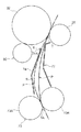
まず、画像形成装置10の構成を説明する。図1は、画像形成装置10の構成を示す概略図である。
(Configuration of image forming apparatus 10)
First, the configuration of the image forming apparatus 10 will be described. FIG. 1 is a schematic diagram illustrating a configuration of the image forming apparatus 10.
画像形成装置10は、図1に示されるように、各構成部品が内部に収容される装置本体11を備えている。装置本体11の内部には、用紙等の記録媒体Pが収容される複数の収容部12と、記録媒体Pに画像を形成する画像形成部14と、画像形成部14によって記録媒体Pに形成された画像を当該記録媒体Pに定着する定着装置56と、収容部12から画像形成部14へ記録媒体Pを搬送する搬送部16と、画像形成装置10の各部の動作を制御する制御部20と、が設けられている。また、装置本体11の上部には、定着装置56によって画像が定着された記録媒体Pが排出される排出部18が設けられている。
As shown in FIG. 1, the image forming apparatus 10 includes an apparatus
画像形成部14は、画像を保持する感光体ドラム32(画像保持体の一例)を有している。感光体ドラム32は、一方向(例えば、図1における反時計回り方向)へ回転するようになっている。感光体ドラム32の周囲には、感光体ドラム32の回転方向上流側から順に、感光体ドラム32を帯電させる帯電装置としての帯電ロール23と、帯電ロール23によって帯電した感光体ドラム32を露光して感光体ドラム32に静電潜像を形成する露光装置36と、露光装置36によって感光体ドラム32に形成された静電潜像を現像して黒色のトナー画像を形成する現像装置80と、現像装置80によって感光体ドラム32に形成された黒色のトナー画像を記録媒体Pに転写する転写ロール26(転写体の一例)と、が設けられている。
The
露光装置36は、制御部20から送られた画像信号に基づき静電潜像を形成するようになっている。制御部20から送られる画像信号としては、例えば、制御部20が外部装置から取得した画像信号がある。
The
露光装置36の上方には、トナーが収容されているトナー収容容器58が設けられている。トナー収容容器58の内部には、トナーが収容されているトナー収容室58Aが形成されている。トナー収容容器58と現像装置80との間には、トナー収容容器58のトナー収容室58Aから現像装置80へ向けてトナーを搬送するトナー搬送装置60が設けられている。
A
転写ロール26は、感光体ドラム32に対して接触しており、転写ロール26と感光体ドラム32との間に記録媒体Pを挟むニップ領域T(第1ニップ領域の一例)が形成されている。転写ロール26は、ニップ領域Tにおいて記録媒体Pを感光体ドラム32とで挟んで上側へ搬送し、ニップ領域Tにおいて記録媒体Pに対して、感光体ドラム32に形成されたトナー画像を転写するようになっている。すなわち、ニップ領域Tが、感光体ドラム32に形成されたトナー画像が記録媒体Pに転写される転写位置(転写部)とされている。
The
搬送部16は、各収容部12に収容された記録媒体Pを送り出す送出ロール46と、送出ロール46によって送り出された記録媒体Pが搬送される搬送路48と、各送出ロール46の搬送方向下流側に設けられ各送出ロール46によって送り出された記録媒体Pを下流側(後述のニップ領域TA)へ搬送する搬送ロール対50と、各搬送ロール対50によって搬送された記録媒体Pをニップ領域Tへ搬送するレジロール対70(第1搬送部材及び第2搬送部材の一例)と、を備えている。
The
さらに、搬送部16は、記録媒体Pの非転写面側に対向するように転写ロール26の搬送方向上流側に配置され、記録媒体の先端をニップ領域Tに向けて案内する転写ロール側ガイド72(案内部材の一例)と、転写ロール側ガイド72に案内される記録媒体Pを間において転写ロール側ガイド72に対向するように配置された感光体ドラム側ガイド74(対向側案内部材の一例)と、を備えている。
Further, the
定着装置56は、加熱部材としての加熱ロール56Aと、加圧部材としての加圧ロール56Bと、を備えている。定着装置56では、加熱ロール56Aによる加熱及び加圧ロール56Bによる加圧により、転写ロール26によって記録媒体Pに転写されたトナー画像を、当該記録媒体Pへ定着するようになっている。この定着装置56の上方側(搬送方向下流側)には、トナー画像が定着された記録媒体Pを排出部18へ排出する排出ロール52が設けられている。
The
また、片面にトナー画像が定着された記録媒体Pを反転させて、再びニップ領域Tへ送り戻すための反転搬送路37が、転写ロール26に対する感光体ドラム32とは反対側(図1における右側)に設けられている。記録媒体Pの両面に画像を形成する際には、片面にトナー画像が定着された記録媒体Pが、排出ロール52によりスイッチバックされて反転搬送路37に導かれてニップ領域Tへ送り戻されるようになっている。
Further, the
次に、画像形成装置10における、記録媒体Pへ画像を形成する画像形成動作について説明する。 Next, an image forming operation for forming an image on the recording medium P in the image forming apparatus 10 will be described.
画像形成装置10では、いずれかの収容部12から送出ロール46によって送り出された記録媒体Pが、搬送ロール対50及びレジロール対70によってニップ領域Tへ送り込まれる。
In the image forming apparatus 10, the recording medium P sent out from any of the
一方、画像形成部14では、感光体ドラム32が帯電ロール23によって帯電された後、露光装置36によって露光されて、感光体ドラム32に静電潜像が形成される。当該静電潜像が現像装置80によって現像されて感光体ドラム32に黒色のトナー画像が形成される。この黒色のトナー画像は、転写ロール26によりニップ領域Tにて記録媒体Pへ転写される。
On the other hand, in the
トナー画像が転写された記録媒体Pは、定着装置56へ搬送され、当該トナー画像が定着装置56により定着される。記録媒体Pの片面へのみ画像を形成する場合は、トナー画像が定着された後、記録媒体Pは排出ロール52により排出部18へ排出される。
The recording medium P onto which the toner image has been transferred is conveyed to the
記録媒体Pの両面へ画像を形成する場合には、片面に画像が定着された後、記録媒体Pは、排出ロール52でスイッチバックされ、反転して反転搬送路37へ送り込まれる。さらに、当該記録媒体は、反転搬送路37から再びニップ領域Tへ送り込まれ、画像が記録されていない反対面に、前述と同様に画像が形成され、排出ロール52により排出部18へ排出される。以上のように、一連の画像形成動作が行われる。
When images are formed on both sides of the recording medium P, after the image is fixed on one side, the recording medium P is switched back by the
(要部構成)
レジロール対70は、図1に示されるように、感光体ドラム32及び転写ロール26によるニップ領域Tの直前(ニップ領域Tに対する搬送方向上流側かつニップ領域Tの最も近く)に配置されており、レジロール対70の間には、記録媒体Pを挟むニップ領域TA(第2ニップ領域の一例)が形成されている。
(Main part configuration)
As shown in FIG. 1, the
また、レジロール対70は、搬送ロール対50から搬送された記録媒体Pの先端を幅方向(図1の紙面の前後方向)で揃えてからニップ領域Tへ搬送する機能を有している。具体的には、レジロール対70は、搬送ロール対50から搬送される記録媒体Pの先端がレジロール対70に到達した後も予め定められた期間において駆動を停止することで、記録媒体Pの先端を幅方向(図1の紙面の前後方向)で揃え、先端が揃った状態にて駆動して記録媒体Pを搬送するようになっている。
In addition, the
また、レジロール対70は、転写位置(転写開始位置)と記録媒体Pの先端位置とを合わせるべく、予め定められたタイミングでニップ領域Tへ記録媒体Pを搬送するようになっている。
Further, the
さらに、レジロール対70による記録媒体Pの搬送速度は、感光体ドラム32と転写ロール26とによる記録媒体Pの搬送速度よりも速く設定されている。
Further, the conveyance speed of the recording medium P by the
図2に示されるように、レジロール対70は、感光体ドラム32側(図2の左側)に配置されたレジロール70A(第1搬送部材の一例)の軸中心C3が、転写ロール26側(図2の右側)に配置されたレジロール70B(第2搬送部材の一例)の軸中心C4よりも高い位置に位置するように配置されている。すなわち、レジロール対70の軸中心C3と軸中心C4とを結んだ線LBが水平線Hに対して角度を有しており、レジロール対70のニップ領域TAを通る接線S2が、図2における右斜め上方に延びている。
As shown in FIG. 2, the
これにより、レジロール対70は、レジロール70Bがレジロール70Aに対する斜め下側から記録媒体Pをレジロール70Bとで挟み、図2における右斜め上方へ搬送するようになっている。
Thus, the
感光体ドラム32及び転写ロール26は、感光体ドラム32の軸中心C1が転写ロール26の軸中心C2よりも高い位置に位置するように配置されている。すなわち、感光体ドラム32の軸中心C1と転写ロール26の軸中心C2とを結んだ線LAが水平線Hに対して角度を有しており、感光体ドラム32及び転写ロール26のニップ領域Tを通る接線S1が図2における右斜め上方に延びている。
The
これにより、感光体ドラム32及び転写ロール26は、転写ロール26が感光体ドラム32に対する斜め下側から記録媒体Pを感光体ドラム32とで挟み、図2における右斜め上方へ搬送するようになっている。
As a result, the
レジロール対70による接線S2は、感光体ドラム32及び転写ロール26による接線S1に対して、転写ロール26側(図2における右側)にずれて配置されており、ニップ領域TAとニップ領域Tとの間では交差しないようになっている。すなわち、ニップ領域TAからの記録媒体Pの排出方向が、ニップ領域Tの搬送方向上流端に対して転写ロール26側へずれて設定されている。より具体的には、ニップ領域TAからの記録媒体Pの排出方向が、ニップ領域Tへの記録媒体Pの進入方向に対して転写ロール26側へずれて設定されている。なお、接線S1及び接線S2が、同じ側(例えば、図2における右側)に傾いていればよく、水平線Hに対する線LAの角度と、水平線Hに対する線LBの角度との間に相対的な角度差は必要ない。従って、水平線Hに対する線LAの角度と、水平線Hに対する線LBの角度とが同じであってもよい。
The tangent line S2 due to the
感光体ドラム側ガイド74は、記録媒体Pの転写面側に対向するように感光体ドラム32に対する搬送方向上流側且つレジロール70Aに対する搬送方向下流側に配置されている。感光体ドラム側ガイド74は、レジロール70Aと感光体ドラム32との間で、図2における右斜め上方に沿って直線状に延びている。また、感光体ドラム側ガイド74は、接線S1、S2に比べて、水平線に対して、角度が大きくなっている(鉛直方向に近い角度を有している)。
The photosensitive
なお、感光体ドラム側ガイド74は、転写ロール側ガイド72よりも現像装置80に近接しており、図2に示すように、現像装置80から漏れたクラウドトナーKが、感光体ドラム側ガイド74に付着する場合がある。
The photosensitive
感光体ドラム側ガイド74は、現像装置80の装置本体82(筐体)と一体化されており、現像装置80の装置本体82と感光体ドラム32との間から漏れたクラウドトナーKは、感光体ドラム側ガイド74の下流側端部(上端部)74Aに蓄積しやすくなっている。
The photosensitive
転写ロール側ガイド72は、レジロール対70の記録媒体Pの排出方向側であって且つレジロール対70の接線S2を横切るように(接線S2と交差するように)配置された上流側ガイド部72Aと、上流側ガイド部72Aの上端部から感光体ドラム32側へ延びる下流側ガイド部72Bと、下流側ガイド部72Bの上端部から転写ロール26側へ突出する突出部72Cと、を有している。下流側ガイド部72Bと突出部72Cとによって角部72D(記録媒体の先端ガイド)が形成されている。
The transfer
転写ロール側ガイド72の上流側ガイド部72A及び下流側ガイド部72Bは、レジロール対70で搬送されることでニップ領域TAから排出された記録媒体Pの先端を、感光体ドラム32側(図2における左側)へ案内するようになっている。
The
転写ロール側ガイド72と感光体ドラム側ガイド74との間隔は、上流側ガイド部72A(搬送方向上流側)で下流側ガイド部72B(搬送方向下流側)よりも広くされている。すなわち、後述のようにS字状に湾曲される記録媒体Pが転写ロール側ガイド72における上流側部分(上流側ガイド部72A)で転写ロール側ガイド72側へ凸状になるための第2空間R2が、当該記録媒体Pが転写ロール側ガイド72における下流側部分(下流側ガイド部72B)で感光体ドラム側ガイド74側へ凸状となるための第1空間R1よりも大きくされている。第2空間R2は、転写ロール26側(図2の右側)において空間が広くなっている。
The distance between the transfer
なお、本実施形態では、レジロール対70のニップ領域TAと、角部72Dと、感光体ドラム32及び転写ロール26によるニップ領域Tとは、感光体ドラム32側(図2の左側)から並んで配置されている。
In the present embodiment, the nip area TA of the
また、本実施形態の定着装置56では、定着装置56においてトナー画像が定着された記録媒体Pが、加圧ロール56B側へ凸状に湾曲(カール)するように、加熱ロール56A及び加圧ロール56B(加熱ロール56A及び加圧ロール56Bのニップ部)が構成されている。
Further, in the fixing
(実施形態に係る作用)
次に、実施形態に係る作用を説明する。
(Operation according to the embodiment)
Next, the operation according to the embodiment will be described.
本実施形態では、いずれかの収容部12から送出ロール46によって送り出された記録媒体Pが、搬送ロール対50によって、レジロール対70のニップ領域TAへ搬送される。ニップ領域TAに搬送された記録媒体Pは、レジロール対70によって先端が揃えられて、予め定められたタイミングにて、感光体ドラム32及び転写ロール26によるニップ領域Tに搬送される。
In the present embodiment, the recording medium P sent out from any of the
レジロール対70によってニップ領域TAからニップ領域Tへ搬送される記録媒体Pは、図3に示されるように、まず、レジロール対70を抜けた先端が転写ロール側ガイド72の上流側ガイド部72Aに当たる。その後、当該先端は、上流側ガイド部72A及び下流側ガイド部72Bに案内されて、図4に示されるように、角部72Dに到達する。その後、当該先端は、角部72Dによって、感光体ドラム32へ案内されて、感光体ドラム32に当たり、図5に示されるように、感光体ドラム32の外周に沿って、ニップ領域Tに到達する。
As shown in FIG. 3, the recording medium P transported from the nip area TA to the nip area T by the
先端がニップ領域Tに到達すると、記録媒体Pは、図5に示されるように、先端側が感光体ドラム32と転写ロール26とのニップ領域Tに挟まれて感光体ドラム32と転写ロール26とで搬送され、後端側がレジロール対70のニップ領域TAに挟まれレジロール対70で搬送される状態となる。
When the leading end reaches the nip region T, the recording medium P is sandwiched between the
レジロール対70の記録媒体Pの搬送速度は、感光体ドラム32と転写ロール26とによる記録媒体Pの搬送速度よりも速く設定されているので、ニップ領域Tでの記録媒体Pの搬送量よりも、ニップ領域TAでの搬送量が多くなる。これにより、図6に示されるように、ニップ領域Tとニップ領域TAとの間において、記録媒体Pにたるみ(ループ)Rが徐々に形成される。
Since the conveyance speed of the recording medium P of the
たるみ(ループ)Rは、転写ロール側ガイド72の搬送方向下流側部分(下流側ガイド部72B)で感光体ドラム側ガイド74側(図2における左側)へ凸状とされ、搬送方向上流側部分(上流側ガイド部72A)で転写ロール側ガイド72側(図2における右側)へ凸状とされたS字状に湾曲する。
The slack (loop) R is convex toward the photosensitive
記録媒体Pが、転写ロール側ガイド72の上流側部分(上流側ガイド部72A)で転写ロール側ガイド72側(図2における右側)へ凸状となるのは、レジロール対70が右斜め上側へ記録媒体Pを送り出すためである。
The recording medium P is convex to the transfer roll side guide 72 side (right side in FIG. 2) at the upstream side portion (upstream
また、記録媒体Pが、転写ロール側ガイド72の下流側部分(下流側ガイド部72B)で感光体ドラム側ガイド74側(図2における左側)へ凸状となるのは、感光体ドラム32及び転写ロール26によるニップ領域Tがレジロール対70による接線S2に対して感光体ドラム32側(図2における左側)にずれ、かつ、感光体ドラム32及び転写ロール26に対して左斜め下側から記録媒体Pが進入するようになっているためである。
The recording medium P is convex toward the photosensitive
さらに、本実施形態では、記録媒体Pが転写ロール側ガイド72における上流側部分で転写ロール側ガイド72側へ凸状になるための第2空間R2が、記録媒体Pが転写ロール側ガイド72における下流側部分で感光体ドラム側ガイド74側へ凸状となるための第1空間R1よりも大きくされているので、感光体ドラム側ガイド74側へ凸状となる部分よりも、転写ロール側ガイド72側へ凸状となる部分のたるみ量が大きくなる。
Furthermore, in the present embodiment, the second space R2 for the recording medium P to be convex toward the transfer roll side guide 72 at the upstream side portion of the transfer
なお、ニップ領域Tでの記録媒体Pの搬送量よりもニップ領域TAでの記録媒体Pの搬送量が多くなることで、ニップ領域Tに対する記録媒体Pの押し込み力が発生する。 In addition, since the conveyance amount of the recording medium P in the nip area TA is larger than the conveyance amount of the recording medium P in the nip area T, a pressing force of the recording medium P to the nip area T is generated.
これに対して、ニップ領域Tとニップ領域TAとの間において記録媒体Pのたるみ(ループ)RがC字状に形成される比較例(図7参照)では、S字状のたるみ(ループ)の曲率半径に比べ、C字状のたるみ(ループ)Rの曲率半径が大きいので、記録媒体Pの先端側がニップ領域Tに進入する際(図7の実線で示すたるみが小さい状態)と、記録媒体Pの後端側がニップ領域Tに進入する際(図7の二点鎖線で示すたるみ(ループ)が大きい状態)とでは、ニップ領域Tへ進入する姿勢(進入方向(進入角度))が大きく変動する。 On the other hand, in the comparative example (see FIG. 7) in which the slack (loop) R of the recording medium P is formed in a C shape between the nip region T and the nip region TA, the S-shaped slack (loop). Since the radius of curvature of the C-shaped sag (loop) R is larger than the radius of curvature of the recording medium P, when the leading end side of the recording medium P enters the nip region T (the state indicated by the solid line in FIG. 7 is small), recording is performed. When the rear end side of the medium P enters the nip region T (a state in which the slack (loop) indicated by a two-dot chain line in FIG. 7 is large), the posture (entry direction (entry angle)) of entering the nip region T is large. fluctuate.
記録媒体Pのニップ領域Tへ進入する姿勢が大きく変動することによって、ニップ領域Tに対する記録媒体Pの押し込み力もばらつき、ニップ領域Tにおける記録媒体Pの先端側と後端側での搬送速度の速度変動が発生する。 When the posture of the recording medium P entering the nip region T varies greatly, the pushing force of the recording medium P against the nip region T also varies, and the conveyance speed speed at the front end side and the rear end side of the recording medium P in the nip region T is also varied. Variations occur.
また、比較例では、記録媒体Pの先端が、感光体ドラム側ガイド74で案内されるようになっているので、感光体ドラム側ガイド74に付着したクラウドトナーに接触して、記録媒体Pが汚れる。
In the comparative example, since the leading end of the recording medium P is guided by the photosensitive
また、比較例では、記録媒体Pの先端が、現像装置80の装置本体82と一体化された感光体ドラム側ガイド74で案内されるようになっているので、記録媒体Pとして厚紙などを用いた場合では、記録媒体Pの先端が感光体ドラム側ガイド74に強く当たって、現像装置80への衝撃によるトナー画像の乱れ(インパルスバンディング)が発生する場合がある。
In the comparative example, since the leading end of the recording medium P is guided by the photosensitive
これに対して、本実施形態では、前述のように、ニップ領域Tとニップ領域TAとの間において、記録媒体Pのたるみ(ループ)RがS字状に形成されるので、C字状のたるみ(ループ)Rが形成される比較例(図7)に比べ、たるみ(ループ)の曲率半径が小さく、記録媒体Pの先端側がニップ領域Tに進入する際(たるみ(ループ)が小さい状態)と、記録媒体Pの後端側がニップ領域Tに進入する際(たるみ(ループ)が大きい状態)とにおいて、ニップ領域Tへ進入する姿勢(進入方向(進入角度))のバラつきが小さい。すなわち、本実施形態では、記録媒体Pの全長にわたって、感光体ドラム32と転写ロール26とのニップ領域Tへ進入する姿勢のバラつきが抑制される。
On the other hand, in the present embodiment, as described above, the slack (loop) R of the recording medium P is formed in an S shape between the nip region T and the nip region TA. Compared with the comparative example (FIG. 7) in which the sag (loop) R is formed, the radius of curvature of the sag (loop) is small, and the leading end side of the recording medium P enters the nip region T (a state in which the sag (loop) is small). When the rear end side of the recording medium P enters the nip region T (a state where the slack (loop) is large), the variation in the posture (entry direction (entrance angle)) of entering the nip region T is small. That is, in this embodiment, variation in the posture of entering the nip region T between the
さらに、本実施形態では、感光体ドラム側ガイド74側へ凸状となる部分が、転写ロール側ガイド72側へ凸状となる部分よりもたるみ量が少ないので、感光体ドラム側ガイド74側へ凸状となる部分が、転写ロール側ガイド72側へ凸状となる部分よりもたるみ量が多い場合に比べ、感光体ドラム32と転写ロール26とのニップ領域Tへ進入する姿勢のバラつきが抑制される。
Further, in this embodiment, the portion that protrudes toward the photosensitive
このように、ニップ領域Tへ進入する姿勢のバラつきが抑制されるので、ニップ領域Tに対して記録媒体Pが押し込まれる押し込み力のバラつきも抑制され、ニップ領域Tにおける記録媒体Pの先端側と後端側での搬送速度の速度変動が抑制される。これにより、記録媒体Pの先端側と後端側とにおいて、転写されるトナー画像の部分倍率の変動が抑制される。さらに、転写ロール26と記録媒体Pとの隙間(GAP)も、記録媒体Pの先端側と後端側とにおいて変動しないので、転写ロール26と記録媒体Pとの隙間で生じる放電による放電白抜け(画像不良)も抑制される。
As described above, since the variation in the posture of entering the nip region T is suppressed, the variation in the pushing force by which the recording medium P is pushed into the nip region T is also suppressed, and the leading end side of the recording medium P in the nip region T is suppressed. Speed fluctuation of the conveyance speed on the rear end side is suppressed. Thereby, fluctuations in the partial magnification of the transferred toner image are suppressed on the front end side and the rear end side of the recording medium P. Further, since the gap (GAP) between the
また、本実施形態では、記録媒体Pの先端が、転写ロール側ガイド72のみで案内されるので、感光体ドラム側ガイド74に付着したクラウドトナーKに接触せず、記録媒体Pの汚れが抑制される。なお、記録媒体Pの中間部は、感光体ドラム側ガイド74側へ凸状となることで感光体ドラム側ガイド74に接触するが、記録媒体Pのいずれも部分も、感光体ドラム側ガイド74のクラウドトナーKが付着する搬送方向下流端部には、接触しないようになっている。
Further, in this embodiment, since the leading end of the recording medium P is guided only by the transfer
また、本実施形態では、記録媒体Pの先端が、転写ロール側ガイド72のみで案内されるので、記録媒体Pの先端が、現像装置80の装置本体82と一体化された感光体ドラム側ガイド74に接触しないので、記録媒体Pの先端が感光体ドラム側ガイド74に当たることによる現像装置80への衝撃で発生するトナー画像の乱れ(インパルスバンディング)が抑制される。また、記録媒体Pの先端が感光体ドラム側ガイド74に当たることによる衝撃で感光体ドラム側ガイド74に付着したクラウドトナーKが落下することも抑制される。
In this embodiment, since the leading end of the recording medium P is guided only by the transfer
本実施形態では、定着装置56においてトナー画像が定着された記録媒体Pは、加圧ロール56B側へ凸状に湾曲(カール)するので、両面に画像を形成するべく、片面に画像が形成された後、再びニップ領域Tへ搬送された記録媒体Pは、感光体ドラム側ガイド74側に凸状に湾曲した状態で、ニップ領域TAからニップ領域Tへ搬送されるので、記録媒体Pの先端が転写ロール側ガイド72に良好に接触して、転写ロール側ガイド72によって案内される。
In the present embodiment, the recording medium P on which the toner image is fixed by the fixing
また、本実施形態では、レジロール対70のニップ領域TAと、角部72Dと、感光体ドラム32及び転写ロール26によるニップ領域Tとは、感光体ドラム32側(図2の左側)から並んで配置されているので、レジロール対70のニップ領域TAから角部72Dへ搬送されかつ角部72Dで案内されてニップ領域Tへ進入する際の記録媒体Pの姿勢が安定化する。
In the present embodiment, the nip area TA of the
(変形例)
上記の実施形態では、転写ロール26が感光体ドラム32に対して斜め下側から接触する構成であったが、これに限られず、転写ロール26は、感光体ドラム32に対して斜め上側から接触してもよいし、水平方向に接触してもよい。
(Modification)
In the above-described embodiment, the
上記の実施形態では、同様に、レジロール70Bがレジロール70Aに対して斜め下側から接触する構成であったが、これに限られず、ニップ領域TAからの記録媒体Pの排出方向がニップ領域Tへの記録媒体Pの進入方向に対して転写ロール26側へずれている限りにおいて、レジロール70Bが、レジロール70Aに対して斜め上側から接触してもよいし、水平方向に接触してもよい。
In the above embodiment, similarly, the
上記の実施形態では、レジロール対70と、転写ロール26及び感光体ドラム32とは、記録媒体Pを上側に搬送する構成であったが、これに限られず、レジロール対70と、転写ロール26及び感光体ドラム32とが搬送する方向は、例えば、水平方向であってもよく、搬送部材の搬送方向と重力方向とは不問である。
In the above-described embodiment, the
上記の実施形態では、画像保持体の一例として、感光体ドラム32を用いた例について説明したが、これに限られず、例えば、画像保持体の一例として、複数の画像形成部によって形成された画像を記録媒体Pに転写する中間転写体(中間転写ベルト、中間転写ドラム等)を用いてもよい。
In the above embodiment, the example using the
本発明は、上記の実施形態に限るものではなく、種々の変形、変更、改良が可能である。例えば、上記に示した変形例は、適宜、複数を組み合わせて構成しても良い。 The present invention is not limited to the above-described embodiment, and various modifications, changes, and improvements can be made. For example, the modification examples described above may be appropriately combined.
10 画像形成装置
16 搬送部
26 転写ロール(転写体の一例)
32 感光体ドラム(画像保持体の一例)
70A レジロール(第1搬送部材の一例)
70B レジロール(第2搬送部材の一例)
72 転写ロール側ガイド(案内部材の一例)
74 感光体ドラム側ガイド(対向側案内部材の一例)
P 記録媒体
R1 第1空間
R2 第2空間
T ニップ領域(第1ニップ領域の一例)
TA ニップ領域(第2ニップ領域の一例)
DESCRIPTION OF SYMBOLS 10
32 Photosensitive drum (an example of an image carrier)
70A registration roll (an example of a first conveying member)
70B registration roll (an example of a second conveying member)
72 Transfer roll side guide (an example of a guide member)
74 Photosensitive drum side guide (an example of a facing side guide member)
P Recording medium R1 First space R2 Second space T Nip area (an example of a first nip area)
TA nip area (example of second nip area)
Claims (2)
潜像を現像して前記画像を形成する現像装置と、
前記画像保持体との第1ニップ領域で記録媒体を挟んで搬送し、該記録媒体の転写面に前記画像を転写する転写体と、
前記記録媒体の転写面側に接触するように前記画像保持体に対する搬送方向上流側に配置された第1搬送部材と、
前記第1搬送部材との第2ニップ領域で前記記録媒体を挟んで前記第1ニップ領域に搬送し、前記第2ニップ領域からの前記記録媒体の排出方向が、前記第1ニップ領域の搬送方向上流端に対して前記転写体側へずれて設定された第2搬送部材と、
前記第2ニップ領域に対する前記排出方向に設けられ、前記第2ニップ領域から排出された前記記録媒体を前記画像保持体側へ案内する案内部材と、
前記現像装置の装置本体と一体化され、前記案内部材に案内される前記記録媒体を間において該案内部材に対向するように配置された対向側案内部材と、
を備え、
前記案内部材における前記記録媒体が最初に接触する接触面に沿って前記対向側案内部材側へ延びる仮想線と前記対向側案内部材との交点が、前記対向側案内部材における前記搬送方向の下流側端部よりも該搬送方向の上流側に存在し、
前記画像保持体及び前記転写体の前記第1ニップ領域を通る接線と前記対向側案内部材との交点が、前記下流側端部よりも該搬送方向の上流側に存在し、
前記第1搬送部材及び前記第2搬送部材は、前記記録媒体の先端が前記案内部材のみで案内されるように記録媒体を搬送し、
前記第2ニップ領域は、前記案内部材における前記記録媒体が最後に接触する接触面に沿って前記搬送方向上流側へ延びる仮想線よりも前記対向側案内部材側に配置されている
画像形成装置。 An image carrier for holding an image;
A developing device for developing the latent image to form the image;
A transfer body that conveys the recording medium in a first nip region with the image holding body, and transfers the image to a transfer surface of the recording medium;
A first conveying member disposed on the upstream side in the conveying direction with respect to the image holding member so as to contact the transfer surface side of the recording medium;
The recording medium is sandwiched in a second nip area with the first conveying member and conveyed to the first nip area, and the discharge direction of the recording medium from the second nip area is the conveying direction of the first nip area. A second conveying member set to be shifted toward the transfer body with respect to the upstream end;
A guide member that is provided in the discharge direction with respect to the second nip region and guides the recording medium discharged from the second nip region toward the image carrier;
An opposing guide member that is integrated with the apparatus main body of the developing device and is disposed so as to face the guide member between the recording medium guided by the guide member;
With
The intersection of the imaginary line extending to the opposing guide member side along the contact surface with which the recording medium first contacts the guide member and the opposing guide member is the downstream side in the transport direction of the opposing guide member. Exists upstream of the end in the conveying direction,
An intersection of a tangent line passing through the first nip region of the image holding body and the transfer body and the opposing guide member exists on the upstream side in the transport direction from the downstream end,
The first conveying member and the second conveying member convey a recording medium so that a tip of the recording medium is guided only by the guide member,
The image forming apparatus, wherein the second nip region is disposed on the opposite guide member side with respect to an imaginary line extending upstream in the transport direction along a contact surface of the guide member with which the recording medium comes into contact last .
前記記録媒体が前記案内部材における搬送方向下流側部分で前記案内部材とは反対側へ凸状となるための第1空間と、 A first space for the recording medium to be convex toward the opposite side of the guide member at a downstream side portion in the transport direction of the guide member;
前記第1空間よりも大きくされ、前記記録媒体が前記案内部材における搬送方向上流側部分で前記案内部材側へ凸状になるための第2空間と、 A second space that is larger than the first space, and the recording medium is convex toward the guide member at an upstream portion in the transport direction of the guide member;
を形成している Forming
請求項1に記載の画像形成装置。 The image forming apparatus according to claim 1.
Priority Applications (1)
| Application Number | Priority Date | Filing Date | Title |
|---|---|---|---|
| JP2013062599A JP6070335B2 (en) | 2013-03-25 | 2013-03-25 | Image forming apparatus |
Applications Claiming Priority (1)
| Application Number | Priority Date | Filing Date | Title |
|---|---|---|---|
| JP2013062599A JP6070335B2 (en) | 2013-03-25 | 2013-03-25 | Image forming apparatus |
Publications (3)
| Publication Number | Publication Date |
|---|---|
| JP2014186255A JP2014186255A (en) | 2014-10-02 |
| JP2014186255A5 JP2014186255A5 (en) | 2015-05-14 |
| JP6070335B2 true JP6070335B2 (en) | 2017-02-01 |
Family
ID=51833869
Family Applications (1)
| Application Number | Title | Priority Date | Filing Date |
|---|---|---|---|
| JP2013062599A Active JP6070335B2 (en) | 2013-03-25 | 2013-03-25 | Image forming apparatus |
Country Status (1)
| Country | Link |
|---|---|
| JP (1) | JP6070335B2 (en) |
Families Citing this family (2)
| Publication number | Priority date | Publication date | Assignee | Title |
|---|---|---|---|---|
| JP7210922B2 (en) * | 2018-07-23 | 2023-01-24 | 富士フイルムビジネスイノベーション株式会社 | Guide structure, image forming apparatus |
| JP7379840B2 (en) | 2019-03-25 | 2023-11-15 | 富士フイルムビジネスイノベーション株式会社 | Transfer section and image forming device |
Family Cites Families (5)
| Publication number | Priority date | Publication date | Assignee | Title |
|---|---|---|---|---|
| JP2710997B2 (en) * | 1989-09-16 | 1998-02-10 | キヤノン株式会社 | Transfer device |
| JP2000112190A (en) * | 1998-10-07 | 2000-04-21 | Canon Inc | Image forming device |
| JP2005008391A (en) * | 2003-06-20 | 2005-01-13 | Toshiba Corp | Image forming device |
| JP2010107636A (en) * | 2008-10-29 | 2010-05-13 | Kyocera Mita Corp | Image forming apparatus |
| JP2011137866A (en) * | 2009-12-25 | 2011-07-14 | Samsung Yokohama Research Institute Co Ltd | Image forming apparatus |
-
2013
- 2013-03-25 JP JP2013062599A patent/JP6070335B2/en active Active
Also Published As
| Publication number | Publication date |
|---|---|
| JP2014186255A (en) | 2014-10-02 |
Similar Documents
| Publication | Publication Date | Title |
|---|---|---|
| JP2011039480A (en) | Image forming apparatus | |
| JP2018043887A (en) | Sheet transportation device, image forming apparatus, and manufacturing method of sheet transportation device | |
| JP5531418B2 (en) | Image forming apparatus | |
| JP5783750B2 (en) | Image forming apparatus | |
| US9483007B2 (en) | Image forming apparatus | |
| JP6330728B2 (en) | Image forming apparatus | |
| JP6070335B2 (en) | Image forming apparatus | |
| JP6493129B2 (en) | Image forming apparatus | |
| JP5358500B2 (en) | Image forming apparatus | |
| JP2017078788A (en) | Image forming apparatus | |
| JP6029092B2 (en) | Image forming apparatus | |
| JP5974941B2 (en) | Image forming apparatus | |
| JP2005179068A (en) | Supported element skew removing system and its method | |
| JP2009166993A (en) | Curl correction method for transfer material, and image forming device | |
| JP7087658B2 (en) | Image forming device | |
| JP2011013381A (en) | Image forming apparatus | |
| JP5346710B2 (en) | Image forming apparatus | |
| JP2022025561A (en) | Image forming apparatus | |
| JP2011095632A (en) | Image forming apparatus | |
| JP6391351B2 (en) | Sheet detecting apparatus and image forming apparatus | |
| JP6596868B2 (en) | Recording material conveying apparatus and image forming apparatus | |
| JP5610918B2 (en) | Sheet body conveying apparatus and image forming apparatus provided with the sheet body conveying apparatus | |
| JP2011257683A (en) | Image forming apparatus | |
| JP2011105410A (en) | Paper carrying device and image forming device | |
| JP2019156614A (en) | Sheet carrier and image forming apparatus comprising same |
Legal Events
| Date | Code | Title | Description |
|---|---|---|---|
| A621 | Written request for application examination |
Free format text: JAPANESE INTERMEDIATE CODE: A621 Effective date: 20150306 |
|
| A521 | Written amendment |
Free format text: JAPANESE INTERMEDIATE CODE: A523 Effective date: 20150325 |
|
| A131 | Notification of reasons for refusal |
Free format text: JAPANESE INTERMEDIATE CODE: A131 Effective date: 20160119 |
|
| A521 | Written amendment |
Free format text: JAPANESE INTERMEDIATE CODE: A523 Effective date: 20160317 |
|
| A131 | Notification of reasons for refusal |
Free format text: JAPANESE INTERMEDIATE CODE: A131 Effective date: 20160628 |
|
| A521 | Written amendment |
Free format text: JAPANESE INTERMEDIATE CODE: A523 Effective date: 20160822 |
|
| TRDD | Decision of grant or rejection written | ||
| A01 | Written decision to grant a patent or to grant a registration (utility model) |
Free format text: JAPANESE INTERMEDIATE CODE: A01 Effective date: 20161206 |
|
| A61 | First payment of annual fees (during grant procedure) |
Free format text: JAPANESE INTERMEDIATE CODE: A61 Effective date: 20161219 |
|
| R150 | Certificate of patent or registration of utility model |
Ref document number: 6070335 Country of ref document: JP Free format text: JAPANESE INTERMEDIATE CODE: R150 |
|
| S533 | Written request for registration of change of name |
Free format text: JAPANESE INTERMEDIATE CODE: R313533 |
|
| R350 | Written notification of registration of transfer |
Free format text: JAPANESE INTERMEDIATE CODE: R350 |