JP6068665B2 - Folded tube supply cassette - Google Patents
Folded tube supply cassette Download PDFInfo
- Publication number
- JP6068665B2 JP6068665B2 JP2015539575A JP2015539575A JP6068665B2 JP 6068665 B2 JP6068665 B2 JP 6068665B2 JP 2015539575 A JP2015539575 A JP 2015539575A JP 2015539575 A JP2015539575 A JP 2015539575A JP 6068665 B2 JP6068665 B2 JP 6068665B2
- Authority
- JP
- Japan
- Prior art keywords
- wall
- annular body
- cassette
- annular
- cover
- Prior art date
- Legal status (The legal status is an assumption and is not a legal conclusion. Google has not performed a legal analysis and makes no representation as to the accuracy of the status listed.)
- Active
Links
- 230000007246 mechanism Effects 0.000 claims description 13
- 230000009975 flexible effect Effects 0.000 description 32
- 210000002105 tongue Anatomy 0.000 description 24
- 239000000463 material Substances 0.000 description 14
- 239000002699 waste material Substances 0.000 description 11
- 230000002093 peripheral effect Effects 0.000 description 6
- 230000008901 benefit Effects 0.000 description 5
- 230000013011 mating Effects 0.000 description 4
- 238000013461 design Methods 0.000 description 3
- 238000000034 method Methods 0.000 description 3
- 238000012986 modification Methods 0.000 description 3
- 230000004048 modification Effects 0.000 description 3
- 238000009423 ventilation Methods 0.000 description 3
- 238000007373 indentation Methods 0.000 description 2
- 238000012856 packing Methods 0.000 description 2
- 230000001174 ascending effect Effects 0.000 description 1
- 230000004888 barrier function Effects 0.000 description 1
- 230000008859 change Effects 0.000 description 1
- 239000002783 friction material Substances 0.000 description 1
- 229920001903 high density polyethylene Polymers 0.000 description 1
- 239000004700 high-density polyethylene Substances 0.000 description 1
- 230000002452 interceptive effect Effects 0.000 description 1
- 239000004033 plastic Substances 0.000 description 1
- 229920003023 plastic Polymers 0.000 description 1
- 238000003825 pressing Methods 0.000 description 1
- 230000008569 process Effects 0.000 description 1
- 238000012545 processing Methods 0.000 description 1
- 238000004904 shortening Methods 0.000 description 1
- 229920001169 thermoplastic Polymers 0.000 description 1
- 239000004416 thermosoftening plastic Substances 0.000 description 1
Images


Classifications
-
- B—PERFORMING OPERATIONS; TRANSPORTING
- B65—CONVEYING; PACKING; STORING; HANDLING THIN OR FILAMENTARY MATERIAL
- B65H—HANDLING THIN OR FILAMENTARY MATERIAL, e.g. SHEETS, WEBS, CABLES
- B65H5/00—Feeding articles separated from piles; Feeding articles to machines
- B65H5/28—Feeding articles stored in rolled or folded bands
-
- B—PERFORMING OPERATIONS; TRANSPORTING
- B65—CONVEYING; PACKING; STORING; HANDLING THIN OR FILAMENTARY MATERIAL
- B65D—CONTAINERS FOR STORAGE OR TRANSPORT OF ARTICLES OR MATERIALS, e.g. BAGS, BARRELS, BOTTLES, BOXES, CANS, CARTONS, CRATES, DRUMS, JARS, TANKS, HOPPERS, FORWARDING CONTAINERS; ACCESSORIES, CLOSURES, OR FITTINGS THEREFOR; PACKAGING ELEMENTS; PACKAGES
- B65D85/00—Containers, packaging elements or packages, specially adapted for particular articles or materials
- B65D85/02—Containers, packaging elements or packages, specially adapted for particular articles or materials for annular articles
- B65D85/04—Containers, packaging elements or packages, specially adapted for particular articles or materials for annular articles for coils of wire, rope or hose
-
- B—PERFORMING OPERATIONS; TRANSPORTING
- B65—CONVEYING; PACKING; STORING; HANDLING THIN OR FILAMENTARY MATERIAL
- B65F—GATHERING OR REMOVAL OF DOMESTIC OR LIKE REFUSE
- B65F1/00—Refuse receptacles; Accessories therefor
- B65F1/0006—Flexible refuse receptables, e.g. bags, sacks
-
- B—PERFORMING OPERATIONS; TRANSPORTING
- B65—CONVEYING; PACKING; STORING; HANDLING THIN OR FILAMENTARY MATERIAL
- B65F—GATHERING OR REMOVAL OF DOMESTIC OR LIKE REFUSE
- B65F1/00—Refuse receptacles; Accessories therefor
- B65F1/04—Refuse receptacles; Accessories therefor with removable inserts
- B65F1/06—Refuse receptacles; Accessories therefor with removable inserts with flexible inserts, e.g. bags or sacks
- B65F1/062—Refuse receptacles; Accessories therefor with removable inserts with flexible inserts, e.g. bags or sacks having means for storing or dispensing spare bags
-
- B—PERFORMING OPERATIONS; TRANSPORTING
- B65—CONVEYING; PACKING; STORING; HANDLING THIN OR FILAMENTARY MATERIAL
- B65F—GATHERING OR REMOVAL OF DOMESTIC OR LIKE REFUSE
- B65F2210/00—Equipment of refuse receptacles
- B65F2210/167—Sealing means
- B65F2210/1675—Sealing means by twisting, e.g. of a flexible tube
-
- B—PERFORMING OPERATIONS; TRANSPORTING
- B65—CONVEYING; PACKING; STORING; HANDLING THIN OR FILAMENTARY MATERIAL
- B65F—GATHERING OR REMOVAL OF DOMESTIC OR LIKE REFUSE
- B65F2210/00—Equipment of refuse receptacles
- B65F2210/181—Ventilating means, e.g. holes
-
- B—PERFORMING OPERATIONS; TRANSPORTING
- B65—CONVEYING; PACKING; STORING; HANDLING THIN OR FILAMENTARY MATERIAL
- B65F—GATHERING OR REMOVAL OF DOMESTIC OR LIKE REFUSE
- B65F2240/00—Types of refuse collected
- B65F2240/132—Diapers
Landscapes
- Engineering & Computer Science (AREA)
- Mechanical Engineering (AREA)
- Refuse Receptacles (AREA)
- Stackable Containers (AREA)
- Apparatus Associated With Microorganisms And Enzymes (AREA)
- Containers And Plastic Fillers For Packaging (AREA)
- Packaging Of Annular Or Rod-Shaped Articles, Wearing Apparel, Cassettes, Or The Like (AREA)
- Rigid Containers With Two Or More Constituent Elements (AREA)
- Packages (AREA)
Description
関連出願への相互参照
[0001]本出願は、「CASSETTE FOR DISPENSING PLEATED TUBING」という名称で2012年11月28日出願の米国特許出願第13/688,139号および「CASSETTE」という名称で2012年10月24日出願の米国意匠特許出願第29/435,445号の出願日の利益を組み込んで主張し、これら両方の全体を参照により援用して本明細書の一部とする。
Cross-reference to related applications
[0001] This application is filed under US Patent Application No. 13 / 688,139 filed Nov. 28, 2012 under the name “CASSETTE FOR DISPENSING PLATETED TUBING” and filed Oct. 24, 2012 under the name “CASSSETTE”. The benefit of the filing date of US Design Patent Application No. 29 / 435,445 is incorporated and claimed, both of which are hereby incorporated by reference in their entirety.
[0002]本主題開示はひだ付きチューブを供給するために用いられるカセットに関する。より詳細には、ひだ付きチューブを保管することができ、廃棄物を収集するために処理容器内で使用するように構成されるカセットに関する。 [0002] The present subject disclosure relates to a cassette used to supply pleated tubes. More particularly, it relates to a cassette that can store pleated tubes and is configured for use in a processing vessel to collect waste.
[0003]様々な詰替可能なカセットが廃棄物の処理用に提供されてきた。Richardsらに付与された失効した米国特許第4,934,529号は、廃棄物の処理に適用可能な装置の一例である。弾力のある可撓性チューブがカセットに入れられ、その内部でパックされて、固定された半径方向の蓋で覆われる。 [0003] Various refillable cassettes have been provided for waste disposal. Expired U.S. Pat. No. 4,934,529 to Richards et al. Is an example of an apparatus applicable to waste disposal. A resilient flexible tube is placed in the cassette, packed inside and covered with a fixed radial lid.
[0004]Morandに付与された米国特許第6,974,029号は、従来のフィルム供給カセットの別の例であり、このカセットでは、カセットの頂部に配置された突出する引きはがし部分を用いる必要があり、この突出部分は、カセット本体の外壁の上部に係合する外縁を有し、そこからひだ付きチューブが、上で引用したRichardsらの参考文献とは異なる方向に引き出される。 [0004] US Pat. No. 6,974,029 to Morand is another example of a conventional film supply cassette, which requires the use of a protruding peel-off portion located at the top of the cassette This projecting portion has an outer edge that engages the top of the outer wall of the cassette body, from which the pleated tube is drawn in a different direction than the Richards et al. Reference cited above.
[0005]Webbに付与された米国特許第7,743,588号は、廃棄物保管カセット機器のさらに別の例であり、ここでは、カセット内に保管されたチューブにアクセスするために容器の上部に回転可能に取り付けられたカセット回転器が必要である。 [0005] US Pat. No. 7,743,588, issued to Webb, is yet another example of a waste storage cassette device, where the top of the container is accessed to access the tubes stored in the cassette. Requires a cassette rotator mounted rotatably.
[0006]これらの従来のディスペンサはそれぞれ扱いにくい技法を必要とし、下記の開示によってこれらは克服される。保管カセットを提供するこれらの従来の試みがあまり有効的でないにもかかわらず、便利に組み立てることができる低コストで効率的な保管容器の必要性が存在する。 [0006] Each of these conventional dispensers requires cumbersome techniques, which are overcome by the following disclosure. Despite these prior attempts to provide a storage cassette, there is a need for a low cost and efficient storage container that can be conveniently assembled.
[0007]本開示の様々な例示的な実施形態が、以下の図面を参照して詳細に説明されるが、ここでは同様の参照番号は、同一のまたは同様な構成部品またはステップを指す。 [0007] Various exemplary embodiments of the present disclosure are described in detail with reference to the following drawings, wherein like reference numerals refer to the same or similar components or steps.
[0029]次に、本発明の特定の実施形態を図面を参照しながらより詳細に説明する。
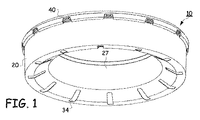
[0030]図1〜4は、本主題開示による例示的なカセット10の下方および上方斜視図および分解斜視図である。カセット10は、断面が概ねU字形の区画を有する下部環状体20、およびU字形溝断面の区画部分を覆って延在する環状カバー40から構成される。
[0029] Specific embodiments of the invention will now be described in more detail with reference to the drawings.
[0030] FIGS. 1-4 are lower and upper perspective and exploded perspective views of an
[0031]図5は、カセット10の分解断面図を示す。下部環状体20は、傾斜壁22に結合する内壁21を含む。傾斜壁22は底壁23に結合し、底壁23は外壁24に結合する。外向きに拡がった傾斜壁25は外壁24の上端に設けられる。外向きに拡がった傾斜壁25は、拡大外壁26の中に入る上端で終端となる。図6に示すように、内壁21、傾斜壁22、底壁23、外壁24、外向きに拡がった傾斜壁25、および拡大外壁26が集合的にハウジングのU字形溝断面を形成し、その中にひだ付き可撓性チューブ50のパック52が受け入れられる。
FIG. 5 shows an exploded cross-sectional view of the
[0032]図5に示すように、カセット10は使用時には支持部材200によって保持される。伸長面202は、支持部材200から水平方向に延在するように設けられて、平坦な棚または面を画定し、その上にU字形環状体20の下壁23を支持することができる。
[0032] As shown in FIG. 5, the
[0033]U字形溝断面の下部の構成および/または傾斜壁22による傾斜の構成は、図6に示すように、また後により詳細に説明するように、パックされたチューブ52として可撓性チューブ50を下部環状体20の中に詰めるときに、空気を下から逃がすために様々な異なった適切な角度にすることができる。例えば、傾斜壁は、図17〜18に示すように、外壁24と内壁21との間を、底壁23無しに直接結合することができ、これは以下でより詳細に説明される。
[0033] The configuration of the lower portion of the U-shaped groove cross section and / or the configuration of tilting by the tilting
[0034]図5を参照すると、U字形環状体20は中央円筒コア27を取り囲んでいる。すなわち、環状体20の内壁21は、円筒状の開放頂部27aおよび円筒状の開放底部27bの構造を有する中央円筒コア27の開口を画定する。
Referring to FIG. 5, the
[0035]図6で示し、後により詳しく説明するように、チューブ50は、下部環状体20のU字形溝断面内に配置されたパックされたチューブ52として示されている。パックされたチューブ52は、U字形溝内に収納され、そこから上方に引っ張られて環状カバー40を通り、内壁21の上縁29を越えて、中央円筒コア27の開口を通って下方に引っ張られるように構成される。
[0035] As shown in FIG. 6 and described in more detail below, the
[0036]図5および特に図9〜10に示すように、環状カバー40は、外側円筒壁41、および外側円筒壁41の頂縁43のわずかに下から延びる内向きに延在する出っ張り42を有し、それによって、環状カバー40に同心の頂部リム44を画定する。図9の部分断面図に示すように、出っ張り42は、下部環状体20を覆って位置決めすると、円筒外壁41から内向きに、中央円筒コア27の内壁21にまでは行かないが、内壁21の方へ延在する。
[0036] As shown in FIG. 5 and in particular FIGS. 9-10, the
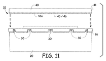
[0037]図9〜12は、環状カバー40の円筒外壁41が下端45を有し、下端45は、下部環状体20のU字形溝の拡大外壁26の内面28(図10に示す)の内側に受け入れられることが可能であることを示している。特に、V字形溝46の環状の上向きリップ46aが、環状カバー40の外壁41の下端45に形成される。図9〜12に示すように、環状V字形溝46は、下部環状体20の拡大外壁26および外向きに拡がった傾斜壁26に画定される突出舌部30とかみ合う。
[0037] In FIGS. 9-12, the cylindrical
[0038]図9および12に示すように、環状カバー40と下部環状体20は定位置に互いに係止的に係合される。環状カバー40が下部環状体20の拡大外壁26内から外れることを防ぐために、図9および12に示すように、環状V字形溝46の上向きリップ46aの外縁が突出舌部30の下縁30aを滑って通りすぎるように環状カバー40が下げられて、環状体20の拡大外壁26の上縁内に位置決めされる。
[0038] As shown in FIGS. 9 and 12, the
[0039]次いで、環状V字形溝46の上向きリップ46aは、突出舌部30の最外縁30aに対して係止される。突出舌部30は戻り止めとして機能して、環状V字形溝46が突出舌部30に対して確実に嵌められた後に、環状カバー40が機械的に留められ、下部環状体20から不必要に持ち上げられ、または引き上げられないようにする。
Next, the upward lip 46 a of the annular V-
[0040]図10および13は、戻り止め機構などの協働して相互に係合する機構のための突出舌部30を形成することができる少なくとも1つの構造を示す。例えば、開口33および突出舌部30は、穿刺具(図示せず)で形成することができる。パックされたチューブ50を装備する前に、または詰めた後に、図11〜13に示すように、突出舌部30は環状体20の上部ケーシングの周りに分散配置することができる。図13は、環状体20の拡大外壁26および外向きに拡がった傾斜壁26の壁において切り離して、開口33、および環状体20の外壁26の周りに内向きに突出する舌部30を生成するために、穿刺具を用いることができることを示す。開口33および突出舌部30の任意の他の適切な構造も形成することができる。
[0040] FIGS. 10 and 13 illustrate at least one structure that can form a protruding
[0041]図13は、突出舌部30が、下縁33a、一対の側縁33b、および突出舌部30の各側の上部切り抜き部分33cによって画定される周囲の開口33を含む例をより詳細に示す。環状カバー40を環状体20に固定する、協働して相互に係合する機構を提供するために様々な他の代替および/または構造があり得ることを理解されたい。例えば、環状体20の突出部と協働する環状カバー40に噛合突出部を設けて、環状カバー40を環状体20に固定する。関連する噛合突出部がお互いを通り越すと、環状カバー40は環状体20に定位置に係止される。
[0041] FIG. 13 illustrates in more detail an example where the protruding
[0042]図14は、一方の上に他方を積み重ねた一対のカセット10a、10bを示す。図15(図14の分解組立断面のA−A部)に示すように、同心の頂部リップまたはリム44は、様々なカセット10a、10bをお互いに積み重ねるのを容易にする。図9〜10および14〜15に示すように、出っ張り42の上面42aは実質的に水平配置で構築される。出っ張り42の上面42aは、2つの積み重ねたカセット10a、10b、および/または2つより多いカセットなどの、お互いに積み重ねられた様々なカセットの重量を保持するのに十分な強度を持っている。
[0042] FIG. 14 shows a pair of
[0043]図14〜15は、外壁24の下縁24aの外周が、同心の頂部リム44の内周面縁44a内にぴったりはまる寸法となっていることをさらに示している。図14に示すように、第2のカセット10bは、下の第1のカセット10aの上に確実に積み重ねることができる。すなわち、外壁24の下縁24aは、高くなっている同心の頂部リム44の内面縁44aの内径によって確実に定位置に保持されるような寸法になっている。この構造によって、積み重ねられた第2のカセット10bが、下のカセット10aの下の環状カバー40の上側に置かれたとき、下のカセット10aの環状カバー40の出っ張り42の頂面42aから滑り落ちないようになっている。
[0043] FIGS. 14-15 further illustrate that the outer periphery of the
[0044]再び図6をより詳細に参照する。構造的には、チューブ50は、内壁21、傾斜壁22、底壁23、および外壁24の間のカセット10のU字形溝の中に密接に束ねられて、大量にかつ密接にひだを付けて層にしたチューブ50の圧縮物またはチューブパック52となっている。チューブ50は、例えば、高密度のポリエチレンチューブおよび/または本主題開示に従う他の任意の適切な材料組成とすることができる。可撓性チューブ50が、下部環状体20のU字形ケーシング内にパック52された後、環状カバー40はチューブ50のひだ付きパック52を覆って配置される。
[0044] Referring again to FIG. 6 in more detail. Structurally, the
[0045]環状カバー40が環状体20上に取り付けられて嵌められるとき、図6および9〜12に示すように、下部環状体20の中に束ねられたパックされたチューブ52は、環状V字形溝46の環状リップ46aの端部が、突出舌部30の下縁30aを滑って通りすぎるまで、わずかに圧縮される。次いで、図9および11〜12に示すように、環状カバー40は離されて、環状V字形溝46の環状リップ46aが、突出舌部30の下向きの縁30aに係止的に係合することができるように上方に戻ることができる。環状カバー40と下部環状体20は、V字形溝46の環状リップ46aにスナップ止め係合するのに適した寸法および形状を有する一連の舌部30の協働によって、お互いに係止的に係合される。
[0045] When the
[0046]図9に示すように、環状カバー40の外壁41の内側円筒面47は、環状体20の外壁24の内側円筒面32と実質的に同じ直径寸法を有するように構築される。円筒外壁41の内側円筒面47と外壁24の内側円筒面32とが実質的に同様な寸法であることによって、パックの組立中に、かつ/またはパックされたチューブ52が元の形に戻るとき、およびチューブ50をカセット10内から引き出して使用するときに、パックされたチューブ52が挟まれたり、ひっかかったり、破れたりするのを防ぐことができる。
[0046] As shown in FIG. 9, the inner
[0047]図16〜17、1〜2、および5は、環状体20の下端に放射状に配置された複数の開口34を示す。図示のように、開口34は細長く、底壁23に配置された第1の端部34aから傾斜壁22と内壁21との交線に隣接して内向きに延在する第2の端部34bまで、長手方向が半径方向に内向きに延在することができる。開口34は傾斜壁22および底壁23に切り込まれ、同心状に放射状に配置することができる。
[0047] FIGS. 16-17, 1-2, and 5 show a plurality of
[0048]開口34は様々な利点を提供する。まず、図5に示すように、パックされた可撓性チューブ52をU字形下部環状体20の中に隙間なく詰めるときに、様々な開口34は通気孔として働いて、パックされたチューブ52の下に閉じ込められる空気を開口34を通して下部環状体20から排出することができる。様々な開口34によって行われる通気によって、そうしなければパックされたチューブ52によって満たされた下部環状体20内の容積に空気が干渉するということがなく、U字形下部環状体20内にパックされたチューブ52がひだ付きのかたまりとして密接に圧縮することができる。その結果、パックされたチューブ52の下には空気は閉じ込められないで、カセット10の中にチューブ50を組み込む際、より密接に詰めることができ、より多くの可撓性チューブ50を圧縮してパックされたチューブ52の状態で下部環状体20内に保管することができる。
[0048]
[0049]図5および6の断面図で示すように、傾斜壁22および開口34の輪郭は、第1の端部34aから上向きに、底壁23の平坦面より上にある、高い位置の第2の端部34bまで傾斜して上昇する。使用時、図5に示すように、カセット10の底壁23は下面202上に置くことができる。そこから上向きの傾斜壁22は上がって、パックされたチューブ50およびU字形下部環状体20の下壁23、22の下に閉じ込められることになる空気の通気を促進する。
[0049] As shown in the cross-sectional views of FIGS. 5 and 6, the contours of the
[0050]図5に示すように、傾斜壁22によって、空気は下部環状体20のU字形溝の下端内から開口34を通って逃げやすくなる。そのようになっていなければ、空気が、支持部材200などの平坦な下面202と接して置かれた底壁23の開口34を通って逃げるのは困難である。傾斜壁22は、チューブのパック52を下部環状体20の中に効率的にかつ迅速に詰めることを促進し、一方、面202と下壁23の塞がれた開口34との間での空気の流れの閉そくを軽減する。開口34は、様々な壁21、22、23、24などの内の任意の1つまたは複数の壁に構築することができることが理解される。
[0050] As shown in FIG. 5, the
[0051]開口34の別の重要な利点は、図5に示すように、カセット10の回転を制御するのを可能にすることである。開口34は、キー穴として機能し、カセット10を中に配置して用いることができる装置(例えば、廃棄物容器)を操作している間、カセット10の回転を制御するために、回転機構62のメイティングキー60をこのキー穴に差し込んで用いることができる。すなわち、キー60は開口34の内の少なくとも1つの開口と合うよう整列させることができる。キー60は、21、22、23、24のいずれの壁の面の開口34の任意の部分に係合することができ、カセット10を回転させたり、または、カセット10の動きを止めることによってカセット10が回転しないようしたりにする。
[0051] Another important advantage of opening 34 is that it allows the rotation of
[0052]また図5に示すように、本主題開示によれば、下部環状体20の上端の舌部30の周りに配置された開口33の構造もまたキー穴として機能し、回転機構62のメイティングキー61をこのキー穴に差し込んでカセットの回転を制御することができることを理解されたい。回転機構62のキー61は開口33の様々な面の内の任意の面に係合することができ、カセット10をつかんだり、カセット10を回転させたり、または回転しないようにする。
[0052] Also, as shown in FIG. 5, according to the present subject disclosure, the structure of the
[0053]開口34、開口33、突出舌部30、ならびに外向きに拡がった傾斜壁25および拡大外壁26に生成される棚自体などはすべて、カセット10をつかんだり、所望の位置に固定したりするなどの様々な目的に用いることができる。同様に、これらの様々な機構は、様々なキー穴および/または輪郭として機能して、それらの中に入るメイティングキー60,61または回転機構62の形状が係合してカセット10を回転させたり、または回転しないようにしたりすることに加えて、カセット10を所定の高さに位置決めするために用いることができる。
[0053] The
[0054]同様に、様々なカラー(図示せず)が、カセット10の一部の周りに嵌められる、かつ/またはカセット10の一部と一体化するように構築、構成することができ、これらは拡張機能となって、カセット10を様々な寸法および形状の様々な異なる装置(例えば、様々なおむつ用バケツ)に改造することができる。カラーは、確実にカセット10をしっかりつかむ、またはカセット10に締結して、カセット設計を様々な異なる装置に広く適用させる拡張部を提供するために、舌部30を囲む開口33、外向きに拡がった傾斜壁25、開口34、および/または他の任意の輪郭を利用することができる。
[0054] Similarly, various collars (not shown) can be constructed and configured to be fitted around and / or integral with a portion of the
[0055]カセット10を中に置く装置(例えば、廃棄物処理装置)内に配置されるカセット10の高さの位置決めは複数の異なるパラメータによって変わり得る。様々なパラメータには、限定はされないが、外壁24の高さの伸長または短縮、外向きに拡がった傾斜壁25と外壁24が合う位置、外向きに拡がった傾斜壁25の長さ、高さ、および角度、拡大外壁26の長さ、ならびに/または傾斜壁22および内壁21の長さ、高さ、および角度が含まれ得る。複数の様々な他の設計パラメータもまた、カセット10とともに用いられる装置内でのカセット10の高さの位置決めを変えるように操作することができる。
[0055] The positioning of the height of the
[0056]開口34は、傾斜壁22と内壁21を横切って延在する等間隔の対称な細長い長方形のスロットとして示されているが、様々な開口34の開口34の数、配置、寸法および/または形状を、本主題開示に従って、任意の数、寸法、対称性、または形状に変えることが可能である。同様に、開口34を外壁24の中まで延ばすこと、またはその代りに、内壁21、傾斜壁22、底壁23、または外壁24の内の任意の1つまたは複数の壁に開口34を設けることもまた可能である。
[0056] Although the
[0057]図6は、可撓性チューブ50がU字形下部環状体20内から引っ張られている状態のカセット10の断面を示す。使用時、カセット10は、(図5に示すように)廃棄物容器などの機器または装置の支持部200に取り付けることができる。可撓性チューブ50はまず、U字形下部環状体20内から、カバー40の内向きに延在する出っ張り42の周縁部49と環状体20の内壁21の滑らかな外側の上縁29との間に画定された開口48を通って引き出すことができる。
FIG. 6 shows a cross section of the
[0058]可撓性チューブ50の最初に引き出す端部の近くに、一端を縛るために結び目が作られてよい。次いで、可撓性チューブ50の結び目が作られた端部は、中央円筒コア27の開口を通して、引っ張る、または押すことができる(チューブの端部が最初は閉じている場合)。可撓性チューブ50は、U字形下部環状体20内のパックのチューブ52から周縁部49と中央円筒コア27の開口との間に画定された開口48を通り、次いで中央円筒コア27の開口壁の滑らかな外側の頂縁29を越えて引き出される。次いで、チューブ50はカセット10の中央円筒コア27を通って引き下ろすことができる。
[0058] A knot may be made near one end of the
[0059]廃棄物は可撓性チューブ50内に入れられ、次いで廃棄物およびその臭いをその中に密閉して閉じ込めるために可撓性チューブ50を捩じることができる。手で捩じることもできるし、またはカセット20の様々な機構と組み合わせて使用することができる他の回転機構(例えば、図5の要素62によって説明した機構)によって捩じることができる。可撓性バッグ50の開口を閉じるための様々な方法は、カセット10とともに使用するために構成された様々な異なる容器装置によって用いることができる。
[0059] The waste can be placed in the
[0060]図9の分解組立図に示すように、中央円筒コア27の頂縁29はわずかに拡大することができる。頂縁29の拡大部の上端は平坦な縁、または曲線状の縁(図示のような)にすることができ、チューブ50がこれを乗り越えるときにチューブ50を傷つけないようにしている。中央円筒コア27の開口の頂縁29は、チューブ50が中央円筒コア27の頂縁29を滑らかに滑って越えるような相互作用を持つ低摩擦係数の材料で作ることができる。同様に、チューブ自体も低摩擦係数の性質を持つ材料で構築することができる。
[0060] As shown in the exploded view of FIG. 9, the
[0061]可撓性チューブ50を容器から引き出すとき、パックされたチューブ52は、図6に示す高いパック位置からU字形下部環状体20内を下方に縮まる。環状カバー40が環状体20の上端より下に落ちて、下部環状体20の下部ケーシング内でくさびになったり、かつ/またはパックされたチューブ52が下部環状体20から外向きに自由に流れるのを妨げたりするのを防ぐために、同心の外向きに拡がった傾斜壁25が、外壁24と拡大外壁26との間で下部環状体20内に形成されて、環状カバー40の下端45が傾斜壁25の高さより低い位置に落ちないよう垂直方向の止め具として働く。
[0061] When the
[0062]突出舌部30は、この工程のいかなる時点においても形成することができる。これらは、可撓性チューブ50が下部環状体20の中に詰められる前、または後で生成することができる。可撓性チューブ50がパックされたチューブ52として下部環状体20内にパックされた後、環状カバー40をかぶせられて、図9および12に示すように、環状V字形溝45が突出舌部30の端部30aを通り過ぎてスナップ止めして、環状カバー40がU字形環状体20から上がって離れないような位置とするのに十分な力でU字形下部環状体20の中へ押すことができる(図11に示すように)。
[0062] The protruding
[0063]以下の特許請求の範囲を逸脱することなく、上記のカセット10、10a、10bに様々な修正がなされ得ることを理解されたい。例えば、拡大外壁26の突出舌部30と嵌合的にかみ合う環状カバー40の環状V字形溝を用いる代わりに、小さなくぼみ、低い突起、および/または浅いエンボス加工の溝でさえも各噛合部品に一体化されて、環状カバー40と下部環状体20との間を確実に結合する。例えば、熱可塑性体のくぼみ(図示せず)が拡大外壁26のケーシングの内面28に(外側からの加熱押圧加工などによって)形成されて、環状カバー40の円筒外壁41の外壁に配置された外周の溝に係合する。この開示の主題に従って、様々な代替が想到される。それぞれの位置で外周の溝とくぼみの位置を逆にする、かつ/または類似の構成など、任意の適切な構成があることを理解されたい。
[0063] It should be understood that various modifications may be made to the
[0064]可撓性チューブ50は様々な異なる寸法および形状に作ることができる。例えば、可撓性チューブ50の直径は約7.6から22.9cm(3から9インチ)で構築することができる。同様に、中央円筒コア27の直径は、例えば約7、6cm(3インチ)など、様々な寸法および形状に構成することができる。
[0064] The
[0065]図5に戻って参照すると、中央円筒コア27は連続する等距離の直径とすることができる、または中央円筒コア27の一端27aが他端27bよりも大きくなるように傾斜させることもできる。図5および6は、中央円筒コア27の上端27aの直径が小さく、中央円筒コア27の下端27bの全径が大きい例を示している。
[0065] Referring back to FIG. 5, the central
[0066]カセット10の寸法と形状は、本主題開示に従うだ円、長方形、および/または任意の適切な寸法または形状など任意の適切な寸法および/または形状にすることができる。示した図は、単なる例示であり、本主題開示に従う広い範囲の寸法が可能である。
[0066] The dimensions and shape of the
[0067]カセット10の下部環状体20またはカバー40は、本主題開示に従う様々な適切な材料から構成することができる。例えば、様々な部品は、ポリポリプロピレンなどの硬質プラスチック材料、および/または互いに確実なスナップフィット結合が可能な任意の他の適切な材料から作ることができる。可撓性チューブ50は、本開示に従って、可撓性チューブ50内の廃棄物の臭いを封止、低減することができるバリアフィルムで形成することができる。
[0067] The
[0068]図17は、カセット10の環状体20の代替の傾斜壁22a構成の断面図を示す。傾斜壁22aは様々な異なる構成をとることができる。図示のように、傾斜壁22aは外壁24と内壁21との間に取り付けられて下部環状体20のU字形溝の下部傾斜面を形成する。傾斜壁22aは上向きに傾斜し、外壁24の下端から内壁21の下端へ上るように延在する。
[0068] FIG. 17 shows a cross-sectional view of an alternative
[0069]複数の開口34が傾斜壁22aに設けられる。前と同じように、開口34は細長く、外壁24に隣接して配置される第1の端部34aから内壁21に隣接して配置される第2の端部34bまで、傾斜壁22aに長手方向が半径方向に延在する。開口34は、傾斜壁22aに切り込まれ、同心状に放射状に配置される。
[0069] A plurality of
[0070]傾斜壁22aおよび開口34の輪郭は、第1の端部34aから上向きに、カセット10を上に置くことができる平坦な下面(例えば、図5に示す支持面202)より上にある第2の端部34bまで傾斜して上昇する。傾斜壁22aが上る構成は、パックされたチューブ52の下で下部環状壁22aの上に閉じ込められる空気を下部環状体20内から周囲の環境内へ排出することができる点で有利である。
[0070] The contours of the
[0071]図18は、カセット10の下部環状体20の傾斜壁22b構成のさらに別の断面図を示す。図示のように、傾斜壁22bは、外壁24の下端と内壁21の下端の間を下向きの角度で下がって、下部環状体20のU字形溝の下部傾斜面を形成する。
[0071] FIG. 18 shows yet another cross-sectional view of the
[0072]同様に、複数の開口34は、通気および回転制御のために傾斜壁22bに設けられる。前と同じように、開口34は細長く、外壁24に隣接して配置される第1の端部34aから内壁21に隣接して配置される第2の端部34bまで下がるように、傾斜壁22bに長手方向が半径方向に延在する。開口34は、傾斜壁22bに切り込まれ、同心状に放射状に配置される。
[0072] Similarly, a plurality of
[0073]傾斜壁22bおよび開口34の輪郭は、第1の端部34aから下向きに第2の端部34bまで、およびカセット10を上に置くことができる平坦な下面(例えば、図5に示す支持面202)の上で、傾斜して下がる。この構成の利点は、U字形下部環状体20内のパックされたチューブ52の下で下部環状壁22bの上に閉じ込められる空気を周囲の環境内へ排出することである。
[0073] The profile of the sloped
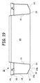
[0074]図19は、底壁23が内壁21に隣接して配置されるカセット10の別の例示的な断面図を示す。同様に、傾斜壁22は、外壁24の下端と底壁23の下端との間に構築されて下部環状体20内のU字形溝の下部傾斜面を形成する。図示のように、傾斜壁22は、外壁24から底壁23まで傾斜して下向きに下がる。
FIG. 19 shows another exemplary cross-sectional view of the
[0075]複数の開口34が傾斜壁22に設けられる。前と同じように、開口34は細長く、傾斜壁22内から底壁23内へ長手方向が半径方向に延在する。開口34の第1の端部34aは、外壁24の下端に隣接する傾斜壁22に配置され、底壁23内へ延在する。開口34は、傾斜壁22および底壁23に切り込まれ、同心状に放射状に配置される。
[0075] A plurality of
[0076]傾斜壁22および開口34の輪郭は、パックされたチューブ52の下でU字形下部環状体20の下部環状壁22の上に閉じ込められる空気を、パックされたチューブ52を組み立てるときに開口34を通して下部環状体20内から周囲の環境内へ排出することができる点で有利である。
[0076] The profile of the
[0077]図20は、環状体120の下部に一体化された可撓性下部環状ベース114を含む圧縮可能なカセット110の断面図を示す。可撓性下部環状ベース114は、通気することができ、かつ/または様々な異なる尖っていない下面および周囲の面の形状に成形できるように柔軟で広い適用性がある。
[0077] FIG. 20 shows a cross-sectional view of a
[0078]可撓性下部環状ベース114は1つまたは複数の可撓性材料から構成することができる。例えば、図20〜21に示すように、環状体120は2つの部分から構成することができる。環状体120の上端112は第1の材料から構成することができ、環状体120の下部環状ベース114は第2の材料から構成することができる。
[0078] The flexible lower
[0079]環状体120の上端112の第1の材料は、環状カバー40を環状体120の上端の舌部30に固定することができる上記のような硬質材料から作ることができる。
[0080]環状体120の下端114の第2の材料は、圧縮されて様々な尖っていない形状および面になることができるより可撓性のある材料から作ることができる。カセット110は、2つの材料として説明したが、圧縮され、成形されて様々な異なる寸法および形状になることができるために十分可撓性のある柔軟な性質を有する単一の材料から構成することができる。
[0079] The first material of the
[0080] The second material at the
[0081]例えば、図21は、使用時に装置(例えば、廃棄物処理装置)の支持部材200によって保持されているカセット110を示す。支持部材200は、U字形環状体120の下端114を上に支持することができる伸長面202を備える。図21に示すように、環状ベース120の下端114は、それに接して配置された尖っていない形状の突出部204を有する面202の上で圧縮することができる。図示のように、環状体120の下端114は突出部204を覆うように柔軟に圧縮されて、環状体120の下端114は、上向きに延在する突出部204の周りを覆う輪郭となる。
[0081] For example, FIG. 21 shows a
[0082]一例で示すように、圧縮可能な下端114を設ける利点は、カセット110が様々な異なる寸法および形状に従うように柔軟に適合することができることである。尖っていない突出部204が環状体120の下面202に隣接して示されているが、任意の尖っていない形状が、カセット110を囲む任意の面上に存在し得ることもまた理解されたい。したがって、圧縮可能なカセット110は、任意の側の任意の形状に従って、それ用に柔軟に適合して使用することができる。一例として、尖っていない表面形状は圧縮可能なカセット110の外側面124、下壁122、内壁121、および/または任意の他の面に隣接して配置することができる。
[0082] As shown by way of example, the advantage of providing a compressible
[0083]本明細書で提供した図および例は、説明のためであって添付の特許請求の範囲を制限することを意図したものではない。本発明の広範な発明的概念から逸脱することなく上記の実施形態に対して変更や修正を行うことができることは当業者であれば認識するであろう。したがって、本発明は、説明された特定の実施形態に限定されるものではなく、本発明の範囲および趣旨の中にあるすべての修正および変更を包含することを意図していることが理解される。
以上説明したように、本発明は以下の形態を有する。
[形態1]
中央円筒コアとともに概ねU字形のハウジングを有する環状体と、
前記環状体を覆って内向きに延在して隙間を画定する環状カバーであって、前記環状体に固定される環状カバーと、
前記環状体の傾斜壁に設けられる少なくとも1つの開口とを備えるひだ付きチューブを供給するのに使用するためのカセット。
[形態2]
前記傾斜壁が前記環状体の内壁と外壁との間に配置される、形態1に記載のカセット。
[形態3]
前記傾斜壁が前記内壁と前記外壁との間で上り傾斜となる、形態1に記載のカセット。
[形態4]
前記傾斜壁が前記内壁と前記外壁との間で下り傾斜となる、形態1に記載のカセット。
[形態5]
前記環状体が下壁をさらに含み、前記傾斜壁が内壁と前記下壁との間に配置される、形態1に記載のカセット。
[形態6]
前記環状体が下壁をさらに含み、前記傾斜壁が外壁と前記下壁との間に配置される、形態1に記載のカセット。
[形態7]
前記開口が前記底壁内へ延在する、形態5に記載のカセット。
[形態8]
前記開口が前記外壁内へ延在する、形態5に記載のカセット。
[形態9]
前記開口が前記内壁内へ延在する、形態5に記載のカセット。
[形態10]
前記開口が前記内壁、前記外壁、および前記底壁の内の少なくとも1つの中へさらに延在する、形態5に記載のカセット。
[形態11]
前記環状カバーが外壁と出っ張りとをさらに備え、前記出っ張りが、前記外壁から半径方向内向きに前記環状体を覆って延在して、前記出っ張りの内縁と前記環状体の前記内壁との間に前記隙間を画定し、
前記外壁が前記半径方向内向きに延在する出っ張りよりわずかに高く延在して同心のリップを画定して、前記カセットの前記環状カバーの前記出っ張りの一部の上に別のカセットが積み重ねられている間、前記別のカセットが前記リップ内に固定することができる、形態2に記載のカセット。
[形態12]
開口した中央円筒コアとともに概ねU字形のハウジングを有する環状体であって、内壁、傾斜壁、および外壁を有する環状体と、
外壁と出っ張りとを有し、前記出っ張りが、前記外壁から半径方向内向きに前記環状体を覆って延在して、前記出っ張りの内縁と前記環状体の前記内壁との間に隙間を画定する、環状カバーと、
協働して前記環状体に前記カバーを固定する、前記環状体と前記環状カバーの対向する縁にある、相互に係合する機構と、
前記傾斜壁に設けられる少なくとも1つの開口とを備えるひだ付きチューブを供給するのに使用するためのカセット。
[形態13]
前記環状体が下壁をさらに含み、前記傾斜壁が内壁と前記下壁との間に配置される、形態12に記載のカセット。
[形態14]
前記環状カバーの前記外壁が前記半径方向内向きに延在する頂部の出っ張りよりわずかに高く延在して同心のリップを画定して、前記環状カバーの前記頂部の出っ張りの一部の上に別のカセットが積み重ねられている間、前記別のカセットが前記リップ内に固定することができる、形態12に記載のカセット。
[形態15]
中央円筒コアとともに概ねU字形のハウジングを有する環状体であって、内壁、傾斜壁、底壁、および外壁を有する環状体と、
外壁と、前記環状体を覆って内向きに延在する頂部の出っ張りとを有する環状カバーであって、前記頂部の出っ張りが前記外壁から半径方向内向きに、前記頂部の出っ張りの内縁と前記内壁との間に隙間を画定する位置まで延在する、環状カバーと、
前記環状体に前記カバーを固定するために、前記環状体と前記環状カバーの対向する縁にある、相互に係合する機構と、
前記傾斜壁に設けられる少なくとも1つの開口とを備えるひだ付きチューブを供給するのに使用するためのカセット。
[形態16]
前記開口が前記底壁内へ延在する、形態15に記載のカセット。
[形態17]
前記開口が前記外壁内へ延在する、形態15に記載のカセット。
[形態18]
前記開口が前記内壁内へ延在する、形態15に記載のカセット。
[形態19]
前記開口が前記内壁、前記外壁、および前記底壁の内の少なくとも1つの中へさらに延在する、形態15に記載のカセット。
[形態20]
前記外壁が前記頂部の出っ張りより上に延在して、上に積み重ねられた別のカセットの環状体の下端を固定するように構成されるリムを画定する、形態15に記載のカセット。
[0083] The figures and examples provided herein are for illustrative purposes and are not intended to limit the scope of the appended claims. Those skilled in the art will recognize that changes and modifications can be made to the above-described embodiments without departing from the broad inventive concept of the present invention. Accordingly, it is to be understood that the invention is not intended to be limited to the specific embodiments described, but is intended to encompass all modifications and variations that fall within the scope and spirit of the invention. .
As described above, the present invention has the following modes.
[Form 1]
An annulus having a generally U-shaped housing with a central cylindrical core;
An annular cover that extends inwardly over the annular body and defines a gap, the annular cover being fixed to the annular body;
A cassette for use in supplying a pleated tube comprising at least one opening provided in an inclined wall of said annular body.
[Form 2]
The cassette according to aspect 1, wherein the inclined wall is disposed between an inner wall and an outer wall of the annular body.
[Form 3]
The cassette according to aspect 1, wherein the inclined wall is inclined upward between the inner wall and the outer wall.
[Form 4]
The cassette according to aspect 1, wherein the inclined wall is inclined downward between the inner wall and the outer wall.
[Form 5]
The cassette according to aspect 1, wherein the annular body further includes a lower wall, and the inclined wall is disposed between an inner wall and the lower wall.
[Form 6]
The cassette according to aspect 1, wherein the annular body further includes a lower wall, and the inclined wall is disposed between an outer wall and the lower wall.
[Form 7]
The cassette of embodiment 5, wherein the opening extends into the bottom wall.
[Form 8]
The cassette of embodiment 5, wherein the opening extends into the outer wall.
[Form 9]
The cassette of embodiment 5, wherein the opening extends into the inner wall.
[Mode 10]
The cassette of embodiment 5, wherein the opening further extends into at least one of the inner wall, the outer wall, and the bottom wall.
[Form 11]
The annular cover further comprises an outer wall and a ledge, the ledge extending radially inward from the outer wall over the annular body, and between the inner edge of the ledge and the inner wall of the annular body. Defining the gap,
Another cassette is stacked over a portion of the ledge of the annular cover of the cassette, with the outer wall extending slightly higher than the radially inwardly extending ledge to define a concentric lip. The cassette of aspect 2, wherein the other cassette can be secured within the lip while
[Form 12]
An annulus having a generally U-shaped housing with an open central cylindrical core, the annulus having an inner wall, an inclined wall, and an outer wall;
An outer wall and a ledge, the ledge extending radially inward from the outer wall over the annular body to define a gap between the inner edge of the ledge and the inner wall of the annular body An annular cover,
An interlocking mechanism at opposite edges of the annular body and the annular cover that cooperates to secure the cover to the annular body;
A cassette for use in supplying a pleated tube comprising at least one opening provided in the inclined wall.
[Form 13]
The cassette according to aspect 12, wherein the annular body further includes a lower wall, and the inclined wall is disposed between an inner wall and the lower wall.
[Form 14]
The outer wall of the annular cover extends slightly above the radially inwardly extending top ledge to define a concentric lip, and is overlying a portion of the top ledge of the annular cover. The cassette of aspect 12, wherein the other cassette can be secured within the lip while the other cassette is being stacked.
[Form 15]
An annular body having a generally U-shaped housing with a central cylindrical core, the annular body having an inner wall, an inclined wall, a bottom wall, and an outer wall;
An annular cover having an outer wall and a top ledge that extends inwardly over the annular body, wherein the top ledge is radially inward from the outer wall, the inner edge of the top ledge and the inner wall An annular cover that extends to a position that defines a gap therebetween;
An interlocking mechanism on opposite edges of the annular body and the annular cover to secure the cover to the annular body;
A cassette for use in supplying a pleated tube comprising at least one opening provided in the inclined wall.
[Form 16]
The cassette of embodiment 15, wherein the opening extends into the bottom wall.
[Form 17]
The cassette of aspect 15, wherein the opening extends into the outer wall.
[Form 18]
The cassette of embodiment 15, wherein the opening extends into the inner wall.
[Form 19]
The cassette of embodiment 15, wherein the opening further extends into at least one of the inner wall, the outer wall, and the bottom wall.
[Form 20]
16. A cassette according to aspect 15, wherein the outer wall extends above the top ledge to define a rim configured to secure a lower end of an annulus of another cassette stacked thereon.
Claims (8)
前記環状体に固定される環状カバーであって、前記環状カバーが外壁と出っ張りとを備え、前記出っ張りが、前記環状カバーの前記外壁から半径方向内向きに前記環状体を覆って延在して、前記出っ張りの内縁と前記環状体の前記内壁との間に隙間を画定し、前記環状カバーの前記外壁が、前記半径方向内向きに延在する出っ張りよりわずかに高く延在して同心のリップを画定する、環状カバーと、
前記環状体の前記傾斜壁に設けられる少なくとも1つの開口とを備えるひだ付きチューブを供給するのに使用するためのカセット。 An annular body having a generally U-shaped housing with a central cylindrical core, the annular body having an inner wall and an inclined wall, the inclined wall being concentric around the annular body and having a frustoconical shape And the inclined wall extends from the inner wall, and an annular body ,
An annular cover fixed to the annular body , wherein the annular cover includes an outer wall and a ledge, and the ledge extends radially inward from the outer wall of the annular cover so as to cover the annular body. Defining a gap between an inner edge of the ledge and the inner wall of the annular body, the outer wall of the annular cover extending slightly higher than the radially inwardly extending ledge and concentric lips Defining an annular cover;
Cassette for use in supplying the pleated tube and at least one aperture provided in the inclined wall of the annular body.
外壁と出っ張りとを有し、前記出っ張りが、前記外壁から半径方向内向きに前記環状体を覆って延在して、前記出っ張りの内縁と前記環状体の前記内壁との間に隙間を画定する、環状カバーと、
協働して前記環状体に前記カバーを固定する、前記環状体と前記環状カバーの対向する縁にある、相互に係合する機構と、
前記傾斜壁に設けられる少なくとも1つの開口とを備えるひだ付きチューブを供給するのに使用するためのカセット。 An annular body having a generally U-shaped housing with an open central cylindrical core, the annular body having an inner wall , an inclined wall, and an outer wall , the inclined wall being concentric around the annular body An annular body that is flat in a frustoconical shape, and wherein the inclined wall extends from the inner wall ;
An outer wall and a ledge, the ledge extending radially inward from the outer wall over the annular body to define a gap between the inner edge of the ledge and the inner wall of the annular body An annular cover,
An interlocking mechanism at opposite edges of the annular body and the annular cover that cooperates to secure the cover to the annular body;
A cassette for use in supplying a pleated tube comprising at least one opening provided in the inclined wall.
外壁と、前記環状体を覆って内向きに延在する頂部の出っ張りとを有する環状カバーであって、前記頂部の出っ張りが前記外壁から半径方向内向きに、前記頂部の出っ張りの内縁と前記内壁との間に隙間を画定する位置まで延在する、環状カバーと、
前記環状体に前記カバーを固定するために、前記環状体と前記環状カバーの対向する縁にある、相互に係合する機構と、
前記傾斜壁に設けられる少なくとも1つの開口とを備えるひだ付きチューブを供給するのに使用するためのカセット。 An annular body having a generally U-shaped housing with a central cylindrical core, the annular body having an inner wall , an inclined wall , a bottom wall, and an outer wall , the inclined wall extending around the annular body An annular body that is concentric and flat in a frustoconical shape, the bottom wall is horizontal and concentrically flat, and the inclined wall extends from the inner wall ;
An annular cover having an outer wall and a top ledge that extends inwardly over the annular body, wherein the top ledge is radially inward from the outer wall, the inner edge of the top ledge and the inner wall An annular cover that extends to a position that defines a gap therebetween;
An interlocking mechanism on opposite edges of the annular body and the annular cover to secure the cover to the annular body;
A cassette for use in supplying a pleated tube comprising at least one opening provided in the inclined wall.
Applications Claiming Priority (5)
| Application Number | Priority Date | Filing Date | Title |
|---|---|---|---|
| US29/435,445 | 2012-10-24 | ||
| US29/435,445 USD695541S1 (en) | 2012-10-24 | 2012-10-24 | Cassette |
| US13/688,139 | 2012-11-28 | ||
| US13/688,139 US9085404B2 (en) | 2012-10-24 | 2012-11-28 | Cassette for dispensing pleated tubing |
| PCT/US2013/029555 WO2014065853A1 (en) | 2012-10-24 | 2013-03-07 | Cassette for dispensing pleated tubing |
Publications (3)
| Publication Number | Publication Date |
|---|---|
| JP2015534929A JP2015534929A (en) | 2015-12-07 |
| JP2015534929A5 JP2015534929A5 (en) | 2016-02-25 |
| JP6068665B2 true JP6068665B2 (en) | 2017-01-25 |
Family
ID=49726018
Family Applications (1)
| Application Number | Title | Priority Date | Filing Date |
|---|---|---|---|
| JP2015539575A Active JP6068665B2 (en) | 2012-10-24 | 2013-03-07 | Folded tube supply cassette |
Country Status (8)
| Country | Link |
|---|---|
| US (5) | USD695541S1 (en) |
| EP (2) | EP3511265B1 (en) |
| JP (1) | JP6068665B2 (en) |
| CN (1) | CN104903214B9 (en) |
| AU (2) | AU2013335318B2 (en) |
| CA (1) | CA2889397C (en) |
| HK (1) | HK1216523A1 (en) |
| WO (1) | WO2014065853A1 (en) |
Families Citing this family (59)
| Publication number | Priority date | Publication date | Assignee | Title |
|---|---|---|---|---|
| USD1011671S1 (en) | 1991-07-02 | 2024-01-16 | Bway Corporation | Container |
| US20050044819A1 (en) | 2003-09-02 | 2005-03-03 | Chomik Richard S. | Waste storage device |
| ES2984298T3 (en) | 2007-10-05 | 2024-10-29 | International Refills Company Ltd | Cassette for dispensing bags from an elongated tube |
| US20150164293A1 (en) * | 2012-08-29 | 2015-06-18 | Nihon Safety Co., Ltd | Folding film cassette and toilet system using the same |
| US10053282B2 (en) | 2012-10-24 | 2018-08-21 | Munchkin, Inc. | Cassette for dispensing pleated tubing |
| USD695541S1 (en) * | 2012-10-24 | 2013-12-17 | Munchkin, Inc. | Cassette |
| US9802756B2 (en) | 2012-11-28 | 2017-10-31 | Munchkin, Inc. | Cassette for dispensing pleated tubing |
| USD739666S1 (en) * | 2013-07-25 | 2015-09-29 | Sangenic International, Ltd. | Cartridge for a waste storage device |
| US10053283B1 (en) | 2013-09-23 | 2018-08-21 | David M Stravitz | Waste container with bag handling assembly |
| US9745127B1 (en) | 2013-09-23 | 2017-08-29 | David M Stravitz | Waste containers with unitary insert |
| US9555962B1 (en) | 2013-09-23 | 2017-01-31 | David M Stravitz | Waste containers with bag trapping structure |
| US9573757B1 (en) | 2013-09-23 | 2017-02-21 | David M Stravitz | Waste treatment components |
| TWD169385S (en) | 2013-10-31 | 2015-08-01 | 科萊恩製造(法國)公司 | Containers |
| USD739615S1 (en) * | 2013-12-23 | 2015-09-22 | Michael Kevin Robertson | Pest free pet feeder |
| USD766716S1 (en) | 2014-04-30 | 2016-09-20 | Clariant Production (France) Sas | Container |
| KR101554682B1 (en) * | 2014-08-01 | 2015-09-21 | 김민영 | wire case |
| EP3218270A4 (en) * | 2014-11-12 | 2018-12-05 | Munchkin, Inc. | Cassette for dispensing pleated tubing |
| WO2016077628A1 (en) * | 2014-11-12 | 2016-05-19 | Munchkin, Inc. | Cassette for dispensing pleated tubing |
| TWD172808S (en) | 2014-11-27 | 2016-01-01 | Clariant Production France Sas | Container |
| USD808680S1 (en) * | 2014-12-03 | 2018-01-30 | Munchkin, Inc. | Cassette |
| EP3230177B1 (en) * | 2014-12-11 | 2021-11-17 | Munchkin, Inc. | Container with waste chamber and supports for flexible bags |
| USD766080S1 (en) * | 2015-02-26 | 2016-09-13 | Clariant Production (France) Sas | Container |
| USD832105S1 (en) * | 2015-03-05 | 2018-10-30 | Envirox, L.L.C. | Container spout |
| USD1000859S1 (en) * | 2015-06-10 | 2023-10-10 | Munchkin Inc. | Cassette |
| CA2989524C (en) * | 2015-06-15 | 2020-10-20 | International Refills Company Ltd. | Cassette and apparatus for use in disposing waste materials into an elongated flexible tube |
| GB201516048D0 (en) * | 2015-09-10 | 2015-10-28 | Sangenic International Ltd | Waste storage device |
| USD764136S1 (en) | 2015-11-09 | 2016-08-16 | David M Stravitz | Bag-retaining insert for waste container |
| USD777394S1 (en) | 2015-11-09 | 2017-01-24 | David M Stravitz | Bag-retaining insert for waste container |
| USD783920S1 (en) | 2015-11-09 | 2017-04-11 | David M Stravitz | Bag-retaining insert for waste container |
| USD767229S1 (en) | 2015-11-09 | 2016-09-20 | David M Stravitz | Bag-retaining insert for waste container |
| USD795606S1 (en) | 2015-12-21 | 2017-08-29 | Sangenic International Limited | Cassette for a waste storage device |
| EP3408195A1 (en) * | 2016-01-28 | 2018-12-05 | Edgewell Personal Care Brands, LLC | Film cassette having an ovoid shape |
| USD766534S1 (en) | 2016-02-26 | 2016-09-13 | David M Stravitz | Bag-securing members for waste containers |
| US9834376B1 (en) | 2016-02-26 | 2017-12-05 | David M Stravitz | Closure components for securing a bag to a container |
| US9694972B1 (en) | 2016-02-26 | 2017-07-04 | David M Stravitz | Rings for securing a bag to a container |
| USD780395S1 (en) | 2016-03-18 | 2017-02-28 | David M Stravitz | Waste container |
| US10006180B2 (en) * | 2016-03-31 | 2018-06-26 | Matthew Weber | Animal waste removal and disposal tool |
| USD775447S1 (en) | 2016-07-06 | 2016-12-27 | David M Stravitz | Pail for use as, for example, a waste container |
| MX2018011434A (en) * | 2016-07-08 | 2019-01-10 | Edgewell Personal Care Brands Llc | A cassette for the collection and storage of waste. |
| WO2019237524A1 (en) * | 2018-06-16 | 2019-12-19 | 上海拓牛智能科技有限公司 | Trash bag component of intelligent trash bin, trash bag laying apparatus, and intelligent trash bin |
| CN108974704A (en) * | 2018-07-03 | 2018-12-11 | 上海拓牛智能科技有限公司 | Rubbish bag assembly and intelligent garbage bin |
| USD920710S1 (en) * | 2019-02-13 | 2021-06-01 | Angelcare Usa, Llc | Waste cassette |
| USD932721S1 (en) * | 2020-02-26 | 2021-10-05 | Bway Corporation | Container ring |
| USD916484S1 (en) | 2019-06-12 | 2021-04-20 | Weihong Yang | Packing box for trash bag |
| TWD205030S (en) * | 2019-09-23 | 2020-06-01 | 黃昱鈞 | Film use device |
| USD904067S1 (en) | 2020-01-15 | 2020-12-08 | Weihong Yang | Packing box for trash bag |
| USD895919S1 (en) * | 2020-02-07 | 2020-09-08 | Dooli Products, LLC | Container with a lid |
| USD895918S1 (en) | 2020-02-07 | 2020-09-08 | Dooli Products, LLC | Vertically oriented container with a lid |
| USD1015669S1 (en) | 2020-02-26 | 2024-02-20 | Bway Corporation | Container ring |
| USD943301S1 (en) * | 2020-04-22 | 2022-02-15 | Angelcare Canada Inc. | Film-dispensing cassette for garbage |
| GB2595721B (en) * | 2020-06-05 | 2022-12-21 | Iatbm Ltd | A device for storing and dispensing an item |
| USD947564S1 (en) * | 2020-07-20 | 2022-04-05 | Guangzhou Qianzhou Envi. Tech. Co., Ltd. | Film-dispensing cassette for garbage |
| EP4211058A1 (en) * | 2020-09-10 | 2023-07-19 | Pario, LLC | Waste management and storage apparatus and method |
| GB2614155B (en) * | 2020-09-28 | 2023-11-29 | Sangenic International Ltd | Waste storage refill |
| GB2600912B (en) * | 2020-09-28 | 2023-04-26 | Sangenic International Ltd | Waste storage refill |
| MX2023011485A (en) * | 2021-03-30 | 2023-10-23 | Angelcare Canada Inc | Film-dispensing cassette for waste-disposal systems. |
| WO2022235844A1 (en) * | 2021-05-04 | 2022-11-10 | Munchkin, Inc. | Flexible bag assembly |
| US11937716B2 (en) | 2021-07-09 | 2024-03-26 | Target Brands, Inc. | Sippy cup having a spoutless training lid assembly |
| USD1021563S1 (en) | 2021-07-09 | 2024-04-09 | Target Brands, Inc. | Combined sippy cup and handle base |
Family Cites Families (73)
| Publication number | Priority date | Publication date | Assignee | Title |
|---|---|---|---|---|
| US2724805A (en) * | 1950-12-02 | 1955-11-22 | Louis D Smullin | Microwave apparatus |
| US2671906A (en) | 1952-11-15 | 1954-03-16 | Robert W Potts | Liner for sanitary closets |
| US2989828A (en) | 1958-09-04 | 1961-06-27 | Flex O Glass Inc | Plastic plant package |
| US3152576A (en) | 1963-07-22 | 1964-10-13 | Faurot George Wesley | Anti-splash watering and feeding device for pet animals |
| USD201670S (en) | 1964-09-09 | 1965-07-20 | Robert D Moore | Plastic feeding tub for animals |
| US3376046A (en) | 1965-03-29 | 1968-04-02 | Jerome S. Kivett | Material handling system |
| US3321103A (en) | 1965-04-27 | 1967-05-23 | Henry E Phillips | Waste disposal device |
| US3401409A (en) | 1966-04-08 | 1968-09-17 | Hans G. Ekrut | Waste disposal unit |
| US3452368A (en) | 1966-10-07 | 1969-07-01 | Fts Corp | Portable waste disposer |
| US3536192A (en) * | 1969-02-17 | 1970-10-27 | John R Couper | Container for incremental withdraw of tubular plastic |
| US3619822A (en) | 1969-11-18 | 1971-11-16 | Thomas Carmichael | Sanitary closet |
| US3602924A (en) | 1970-05-01 | 1971-09-07 | Robert R Kneisley | Commode, storage apparatus or the like |
| US3746159A (en) | 1971-08-19 | 1973-07-17 | Coleman Co | Cartridge package for a sanitary toilet |
| US3938300A (en) | 1972-03-09 | 1976-02-17 | Karl Bo Lennart Lovqvist | Arrangement in refuse chutes |
| US3956510A (en) | 1973-04-19 | 1976-05-11 | Beall Nelson J | Certain mixed antibacterials |
| US4132047A (en) | 1975-03-12 | 1979-01-02 | Hoechst Aktiengesellschaft | Method of making sheathed tubular stick |
| US4085706A (en) | 1976-12-27 | 1978-04-25 | Virginia Sunner Evans | Combined animal weaning, watering and feeding dishes |
| JPS5429272A (en) | 1977-08-08 | 1979-03-05 | Shibaura Eng Works Ltd | Disposer of sink |
| GB0114312D0 (en) * | 2001-06-12 | 2001-08-01 | Sangenic International Ltd | Spool for a waste storage device |
| US4420093A (en) | 1981-12-10 | 1983-12-13 | Holdt J W Von | Molded bucket and lid having high stack strength |
| US4408692A (en) | 1982-04-12 | 1983-10-11 | The Kendall Company | Sterile cover for instrument |
| DE3214673A1 (en) | 1982-04-21 | 1983-10-27 | Hoechst Ag, 6230 Frankfurt | DEVICE FOR THE PRODUCTION OF FILLED TUBULAR SLEEVES |
| USD279949S (en) | 1982-06-10 | 1985-08-06 | Rossin Steven J | Food bowl |
| US4528719A (en) | 1983-06-23 | 1985-07-16 | Union Carbide Corporation | Casing sizing means and method |
| JPS63123701A (en) | 1986-11-10 | 1988-05-27 | 太田 博康 | Refuse pack production unit for automatic set of refuse automatic pack receiver |
| GB8705120D0 (en) | 1987-03-05 | 1987-04-08 | Process Improvements Ltd | Packs of flexible tubing |
| EP0303517A1 (en) | 1987-08-13 | 1989-02-15 | van der Mescht, Leon | Apparatus for dispensing flexible tubing |
| USD302753S (en) | 1987-09-18 | 1989-08-08 | Ethical Products, Inc. | Animal feeding dish |
| GB8818365D0 (en) | 1988-08-02 | 1988-09-07 | Process Improvements Ltd | Cassette containing flexible tubing to be dispensed therefrom |
| GB2221889A (en) | 1988-08-17 | 1990-02-21 | Process Improvements Ltd | Device for packaging objects in flexible tubing |
| DE8813273U1 (en) | 1988-10-22 | 1988-12-15 | Hoechst Ag, 6230 Frankfurt | Gathered packaging tube |
| GB2232951B (en) | 1989-06-19 | 1993-02-24 | Process Improvements Ltd | Apparatus for producing layered tubes or rings |
| USD321572S (en) | 1989-08-14 | 1991-11-12 | The Iams Company | Pet food bowl |
| US5046219A (en) | 1990-08-22 | 1991-09-10 | Teepak, Inc. | Prepackaged shirred food emulsion casing with integral casing sizing and brake control |
| US5230651A (en) | 1991-07-01 | 1993-07-27 | Viskase Corporation | Method and apparatus for severing shirred tubular food casing, and article |
| USD351606S (en) | 1992-01-17 | 1994-10-18 | Sandvik Ab | Cutting insert for milling cutters |
| DE9319683U1 (en) | 1993-12-21 | 1994-04-28 | Kreth Julius | Device for packaging waste |
| GB2292725B (en) | 1994-08-26 | 1998-04-15 | Process Improvements 1989 Ltd | Apparatus for using packs of flexible tubing in packaging |
| US5535913A (en) | 1994-10-20 | 1996-07-16 | Fisher-Price, Inc. | Odorless container |
| USD381472S (en) | 1995-11-03 | 1997-07-22 | Anthony Catalano | Spill catching pet bowl |
| PT861191E (en) | 1995-11-17 | 2000-10-31 | Captiva Holding | DEVICE FOR COLLECTING AND CONFINING HOSPITAL AND DOMESTIC WASTE |
| US5699925A (en) | 1996-05-14 | 1997-12-23 | Petruzzi; Thomas G. | Interlocking stackable container storage system |
| GB9621864D0 (en) | 1996-10-21 | 1996-12-11 | Process Improvements 1989 Ltd | Apparatus for packaging packs of odorous waste in flexible tubing |
| US5813200A (en) | 1996-12-17 | 1998-09-29 | Mondial Industries, Ltd. | Packaging and disposal system |
| EP1324919B1 (en) | 2000-09-07 | 2005-06-01 | Karl-Erik Wessmann | Apparatus for separately sealing a number of objects |
| US6370847B1 (en) | 2000-10-02 | 2002-04-16 | Tim Allan Nygaard Jensen | Sealable diaper-disposal system and method |
| US20020078665A1 (en) | 2000-12-21 | 2002-06-27 | Salman Nabil Enrique | Portable packaging device and method for forming individually packaged articles |
| US20050044819A1 (en) | 2003-09-02 | 2005-03-03 | Chomik Richard S. | Waste storage device |
| US8091325B2 (en) | 2001-05-02 | 2012-01-10 | Playtex Products, Inc. | Waste disposal device including a diaphragm for twisting a flexible tubing dispensed from a cartridge |
| US6612099B2 (en) | 2001-05-02 | 2003-09-02 | Saniquest Industries Corp. | Waste disposal devices including cartridge of flexible tubing |
| CA2366384A1 (en) | 2001-12-31 | 2003-06-30 | Moniteurs Angelcare Inc. | Casssette for dispensing pleated tubing |
| CA2387183C (en) * | 2001-12-31 | 2009-05-12 | Moniteurs Angelcare Inc. | Cassette for dispensing pleated tubing |
| CA2372143A1 (en) | 2002-02-15 | 2003-08-15 | Les Developpements Angelcare Inc. | Apparatus for forming and containing waste containing packs |
| US7100767B2 (en) | 2002-04-17 | 2006-09-05 | Playtex Products, Inc. | Odor transmission-resistant polymeric film |
| US6851251B2 (en) * | 2002-07-31 | 2005-02-08 | Saniquest Industries Corp. | Waste disposal devices |
| US6941733B2 (en) | 2003-04-03 | 2005-09-13 | Playtex Products, Inc. | Waste disposal apparatus |
| US7481393B2 (en) | 2003-05-02 | 2009-01-27 | Thomas Trinko | Produce bag dispensing system for reducing wasted bags |
| GB0324764D0 (en) * | 2003-10-23 | 2003-11-26 | Sangenic International Ltd | Waste storage device |
| US6925781B1 (en) | 2004-02-03 | 2005-08-09 | Playtex Products, Inc. | Integrated cutting tool for waste disposal method and apparatus |
| JP4522114B2 (en) * | 2004-03-12 | 2010-08-11 | ユニ・チャーム株式会社 | Wet tissue container |
| JP4436703B2 (en) * | 2004-03-12 | 2010-03-24 | ユニ・チャーム株式会社 | Sealed package |
| DE202005015081U1 (en) | 2005-09-24 | 2007-02-08 | Melitta Haushaltsprodukte Gmbh & Co. Kg | Cassette for film tube, has housing in which circular retainer is formed, and outlet opening formed in retainer for holding film tube, where housing has internal duct with oval cross section for film tube |
| US20080272140A1 (en) * | 2007-05-04 | 2008-11-06 | Playtex Products, Inc. | Cassette for dispensing flexible tubing therefrom |
| DE202007009842U1 (en) | 2007-07-12 | 2008-11-20 | Sangenic International Ltd., Cramlington | Improved cassette for a waste storage device |
| USD615786S1 (en) * | 2007-09-17 | 2010-05-18 | International Refills Company Limited | Film-dispensing cassette for garbage |
| ES2984298T3 (en) | 2007-10-05 | 2024-10-29 | International Refills Company Ltd | Cassette for dispensing bags from an elongated tube |
| WO2009141583A1 (en) * | 2008-05-19 | 2009-11-26 | Sangenic International Ltd | Waste storage device |
| GB0902471D0 (en) † | 2009-02-13 | 2009-04-01 | Sangenic International Ltd | Waste storage device |
| WO2012109756A1 (en) * | 2011-02-18 | 2012-08-23 | Angelcare Development Inc. | Waste-disposal system for film-dispensing units |
| GB201103429D0 (en) * | 2011-02-28 | 2011-04-13 | Sangenic International Ltd | Improved waste storage device and cassette |
| JP5429272B2 (en) | 2011-12-26 | 2014-02-26 | パナソニック株式会社 | Air conditioner |
| USD695541S1 (en) * | 2012-10-24 | 2013-12-17 | Munchkin, Inc. | Cassette |
| US9802756B2 (en) * | 2012-11-28 | 2017-10-31 | Munchkin, Inc. | Cassette for dispensing pleated tubing |
-
2012
- 2012-10-24 US US29/435,445 patent/USD695541S1/en active Active
- 2012-11-28 US US13/688,139 patent/US9085404B2/en active Active
-
2013
- 2013-03-07 EP EP19158759.1A patent/EP3511265B1/en active Active
- 2013-03-07 CN CN201380061996.0A patent/CN104903214B9/en active Active
- 2013-03-07 WO PCT/US2013/029555 patent/WO2014065853A1/en active Application Filing
- 2013-03-07 AU AU2013335318A patent/AU2013335318B2/en active Active
- 2013-03-07 JP JP2015539575A patent/JP6068665B2/en active Active
- 2013-03-07 EP EP13848754.1A patent/EP2938559B3/en active Active
- 2013-03-07 CA CA2889397A patent/CA2889397C/en active Active
-
2015
- 2015-06-10 US US14/736,192 patent/US10486925B2/en active Active
-
2016
- 2016-04-15 HK HK16104345.6A patent/HK1216523A1/en active IP Right Maintenance
-
2017
- 2017-09-08 AU AU2017225131A patent/AU2017225131B2/en active Active
-
2018
- 2018-09-25 US US16/141,764 patent/US10494211B2/en active Active
-
2019
- 2019-12-03 US US16/701,787 patent/US10913626B2/en active Active
Also Published As
| Publication number | Publication date |
|---|---|
| CN104903214B (en) | 2016-08-24 |
| CN104903214B9 (en) | 2016-11-02 |
| EP2938559B2 (en) | 2022-05-25 |
| JP2015534929A (en) | 2015-12-07 |
| US20150274464A1 (en) | 2015-10-01 |
| CN104903214A (en) | 2015-09-09 |
| EP2938559B1 (en) | 2019-08-21 |
| US10486925B2 (en) | 2019-11-26 |
| AU2017225131A1 (en) | 2017-10-05 |
| US20140110293A1 (en) | 2014-04-24 |
| AU2017225131B2 (en) | 2019-08-08 |
| US10913626B2 (en) | 2021-02-09 |
| EP2938559A4 (en) | 2016-06-22 |
| CA2889397C (en) | 2020-01-28 |
| EP2938559A1 (en) | 2015-11-04 |
| US10494211B2 (en) | 2019-12-03 |
| HK1216523A1 (en) | 2016-11-18 |
| CA2889397A1 (en) | 2014-05-01 |
| AU2013335318B2 (en) | 2017-06-08 |
| AU2013335318A1 (en) | 2015-05-14 |
| US20190023512A1 (en) | 2019-01-24 |
| EP3511265B1 (en) | 2022-06-08 |
| WO2014065853A1 (en) | 2014-05-01 |
| EP2938559B3 (en) | 2023-01-04 |
| US9085404B2 (en) | 2015-07-21 |
| US20200180884A1 (en) | 2020-06-11 |
| EP3511265A1 (en) | 2019-07-17 |
| USD695541S1 (en) | 2013-12-17 |
Similar Documents
| Publication | Publication Date | Title |
|---|---|---|
| JP6068665B2 (en) | Folded tube supply cassette | |
| GB2547595B (en) | Cassette for dispensing pleated tubing | |
| US11130628B2 (en) | Cassette for dispensing pleated tubing | |
| US20180290828A1 (en) | Container for receiving multiple flexible bag assemblies | |
| CA3074061C (en) | Cassette and apparatus for use in disposing waste materials into an elongated flexible tube | |
| CN107207111B (en) | Cassette for dispensing pleated tubing | |
| CA2967801C (en) | Cassette for dispensing pleated tubing | |
| EP2535283A1 (en) | A two lid box | |
| JP5130812B2 (en) | Hot water lid | |
| JPH0652655U (en) | Disposable cup |
Legal Events
| Date | Code | Title | Description |
|---|---|---|---|
| A521 | Request for written amendment filed |
Free format text: JAPANESE INTERMEDIATE CODE: A523 Effective date: 20160105 |
|
| A621 | Written request for application examination |
Free format text: JAPANESE INTERMEDIATE CODE: A621 Effective date: 20160105 |
|
| A871 | Explanation of circumstances concerning accelerated examination |
Free format text: JAPANESE INTERMEDIATE CODE: A871 Effective date: 20160105 |
|
| A975 | Report on accelerated examination |
Free format text: JAPANESE INTERMEDIATE CODE: A971005 Effective date: 20160317 |
|
| A131 | Notification of reasons for refusal |
Free format text: JAPANESE INTERMEDIATE CODE: A131 Effective date: 20160323 |
|
| A601 | Written request for extension of time |
Free format text: JAPANESE INTERMEDIATE CODE: A601 Effective date: 20160620 |
|
| TRDD | Decision of grant or rejection written | ||
| A01 | Written decision to grant a patent or to grant a registration (utility model) |
Free format text: JAPANESE INTERMEDIATE CODE: A01 Effective date: 20161125 |
|
| A61 | First payment of annual fees (during grant procedure) |
Free format text: JAPANESE INTERMEDIATE CODE: A61 Effective date: 20161222 |
|
| R150 | Certificate of patent or registration of utility model |
Ref document number: 6068665 Country of ref document: JP Free format text: JAPANESE INTERMEDIATE CODE: R150 |
|
| R250 | Receipt of annual fees |
Free format text: JAPANESE INTERMEDIATE CODE: R250 |
|
| R250 | Receipt of annual fees |
Free format text: JAPANESE INTERMEDIATE CODE: R250 |
|
| R250 | Receipt of annual fees |
Free format text: JAPANESE INTERMEDIATE CODE: R250 |
|
| R250 | Receipt of annual fees |
Free format text: JAPANESE INTERMEDIATE CODE: R250 |
|
| R250 | Receipt of annual fees |
Free format text: JAPANESE INTERMEDIATE CODE: R250 |