JP6068595B2 - Air conditioner - Google Patents
Air conditioner Download PDFInfo
- Publication number
- JP6068595B2 JP6068595B2 JP2015212704A JP2015212704A JP6068595B2 JP 6068595 B2 JP6068595 B2 JP 6068595B2 JP 2015212704 A JP2015212704 A JP 2015212704A JP 2015212704 A JP2015212704 A JP 2015212704A JP 6068595 B2 JP6068595 B2 JP 6068595B2
- Authority
- JP
- Japan
- Prior art keywords
- notification
- unit
- air conditioning
- air conditioner
- sound
- Prior art date
- Legal status (The legal status is an assumption and is not a legal conclusion. Google has not performed a legal analysis and makes no representation as to the accuracy of the status listed.)
- Active
Links
Images


Landscapes
- Air Conditioning Control Device (AREA)
Description
本発明は空気調和機に関する。 The present invention relates to an air conditioner.
通常用いられている空気調和機は、冷房運転と暖房運転が可能である。最近では節電志向が高まり、空気調和機の使用を控える家庭や企業も多い。しかしながら、夏場、冷房をしないでいると、室内でも熱中症を発症する危険性がある。 Normally used air conditioners are capable of cooling operation and heating operation. Recently, the desire to save electricity has increased, and many homes and businesses refrain from using air conditioners. However, if the air is not cooled in summer, there is a risk of developing heat stroke even indoors.
特許文献1には、上記のような危険を回避するため、使用者が温度センサを身につけ、温度が高くなった場合は自動的に冷房に設定して、熱中症を防止する空気調和システムが記載されている。
特許文献1に開示された熱中症予防対策は、使用者が温度センサを身につける必要があり、煩わしい。また、体温が高くなってしまってから冷房を開始したのでは手遅れになる可能性もある。
The heat stroke prevention measure disclosed in
本発明は上記の点に鑑みなされたものであり、使用者が何も身につけなくても、冷房の必要性を告知する空気調和機を提供することを目的とする。 The present invention has been made in view of the above points, and an object of the present invention is to provide an air conditioner that notifies the necessity of cooling without requiring the user to wear anything.
本発明に係る空気調和システムは、除湿運転または冷房運転が可能な空気調和システムであって、空気調和運転を行う空気調和機本体と、空気調和機本体を遠隔操作することができる遠隔操作装置と、空気調和機システムの制御を行う制御部と、室内温度を検出する温度検出器と、音で告知する告知部と、告知部に音で告知させることを有効にする有効モードと、告知部に音で告知させることを無効にする無効モードのいずれかを設定することができる設定部と、を備え、制御部は、設定部で設定されたモードが有効モードであるとき、告知部に音で告知させることを特徴としている。
また、告知部の告知に基づいて、ユーザーが前記空気調和システムに冷房運転または除湿運転を行わせることができることを特徴としている。
また、冷房運転または除湿運転が開始された後も、室内温度が所定値以上の高温である間は、告知が継続されることを特徴としている。
An air conditioning system according to the present invention is an air conditioning system capable of dehumidifying operation or cooling operation, an air conditioner body that performs air conditioning operation, and a remote control device that can remotely operate the air conditioner body. a control unit for controlling the air conditioner system, a temperature detector for detecting the room temperature, a notification unit for notifying sound, and effective mode to enable be announced in sound notifying unit, the notification unit comprising a setting unit capable of setting one of the disabled mode to disable be notified by sound, the control unit, when the mode set by the setting unit is valid mode, sound notifying unit It is characterized by being notified.
Further, the present invention is characterized in that the user can cause the air conditioning system to perform a cooling operation or a dehumidifying operation based on the notification of the notification unit.
Further, even after the cooling operation or the dehumidifying operation is started, the notification is continued while the room temperature is a high temperature equal to or higher than a predetermined value.
また、本発明に係る空気調和システムは、除湿運転または冷房運転が可能な空気調和システムであって、空気調和運転を行う空気調和機本体と、空気調和機本体を遠隔操作することができる遠隔操作装置と、空気調和機システムの制御を行う制御部と、室内温度を検出する温度検出器と、音で告知する告知部と、告知部に音で告知させることを有効にする有効モードと、告知部に音で告知させることを無効にする無効モードのいずれかを設定することができる設定部と、を備え、遠隔操作装置は開閉可能な設定部を覆う蓋を備えており、蓋を開けたとき設定部を操作することが可能とすることが好ましい。 The air conditioning system according to the present invention is an air conditioning system capable of dehumidifying operation or cooling operation, and an air conditioner body that performs air conditioning operation and a remote operation that can remotely operate the air conditioner body a device, and a control unit for controlling the air conditioner system, a temperature detector for detecting the room temperature, a notification unit for notifying sound, and effective mode to enable be announced in sound notifying unit, announcement And a setting unit that can set any of the invalid modes for disabling sound notification to the unit, and the remote control device includes a lid that covers the setting unit that can be opened and closed, and the lid is opened. Sometimes it is possible to operate the setting section .
また、本発明に係る空気調和システムは、冷房運転が可能な空気調和システムであって、空気調和運転を行う空気調和機本体と、空気調和機本体を遠隔操作することができる遠隔操作装置と、空気調和機システムの制御を行う制御部と、室内温度を検出する温度検出器と、室内湿度を検出する湿度検出器と、音で告知する告知部と、告知部に音で告知させることを有効にする有効モードと、告知部に音で告知させることを無効にする無効モードのいずれか一方を設定することができる設定部と、を備え、制御部は、設定部が有効モードに設定されているとき、温度検出器で測定された室内温度が所定値以上の高温で、かつ、湿度検出器で測定された室内湿度が所定値以上の高湿である場合に、告知部に音で告知させる。
または、温度検出器で測定された温度と、湿度検出器で測定された湿度の少なくともどちらか一方の検出結果に基づき、告知部に告知するか否かの判断を行わせ、温度検出器で測定された温度に基づく検出結果が所定値以上の高温であり、かつ湿度検出器で測定された湿度に基づく検出結果が所定値以上の高湿であるとき、制御部は告知部に告知させるように告知部を制御し、温度検出器で測定された温度に基づく検出結果が所定値以上の高温であり、かつ湿度検出器で測定された湿度に基づく検出結果が所定値未満の低湿であるとき、制御部は告知部に告知させないように告知部を制御しすることを特徴としている。
In addition, the air conditioning system according to the present invention is an air conditioning system capable of cooling operation, an air conditioner body that performs air conditioning operation, a remote control device that can remotely operate the air conditioner body, enable a control unit for controlling the air conditioner system, a temperature detector for detecting the indoor temperature, and humidity detector for detecting indoor humidity, a notification unit for notifying sound, that is announced in sound notifying unit And a setting unit that can set one of an invalid mode that disables the notification unit from making a sound notification, and the control unit has the setting unit set to the valid mode. When the room temperature measured by the temperature detector is higher than the predetermined value and the room humidity measured by the humidity detector is higher than the predetermined value, the notification unit is notified by sound. .
Alternatively, based on the detection result of at least one of the temperature measured by the temperature detector and the humidity measured by the humidity detector, the notification unit determines whether to notify and measures by the temperature detector. When the detection result based on the detected temperature is higher than the predetermined value and the detection result based on the humidity measured by the humidity detector is higher than the predetermined value, the control unit should notify the notification unit. Controlling the notification unit, when the detection result based on the temperature measured by the temperature detector is a high temperature equal to or higher than a predetermined value, and the detection result based on the humidity measured by the humidity detector is a low humidity lower than the predetermined value, The control unit is characterized by controlling the notification unit so that the notification unit is not notified.
また、本発明に係る空気調和システムは、遠隔操作装置に室内温度を検出する温度検出器と、または、室内温度を検出するし温度検出器と音で告知する告知部の両方を備える。 Moreover, the air conditioning system which concerns on this invention is equipped with both the temperature detector which detects indoor temperature in a remote control apparatus, or both the temperature detector and the notification part which notifies by sound with a temperature detector.
また、本発明に係る空気調和システムは、除湿運転または冷房運転が可能な空気調和システムであって、空気調和運転を行う空気調和機本体と、空気調和機本体を遠隔操作することができる遠隔操作装置と、空気調和機システムの制御を行う制御部と、室内温度を検出する温度検出器と、音で告知する告知部と、告知部に音で告知させることを有効にする有効モードと、告知部に音で告知させることを無効にする無効モードのいずれか一方を設定することができる設定部と、を備え、遠隔操作装置は空気調和機と双方向通信を行うことが可能な通信手段である第一の送受信部を有しており、空気調和機本体は遠隔操作装置と双方向通信を行うことが可能な通信手段である第二の送受信部を有しており、遠隔操作装置に備えられた第一の送受信部は遠隔操作装置の向きにかかわらず空気調和機本体に備えられた第二の送受信部と通信可能であることを特徴としている。 The air conditioning system according to the present invention is an air conditioning system capable of dehumidifying operation or cooling operation, and an air conditioner body that performs air conditioning operation and a remote operation that can remotely operate the air conditioner body a device, and a control unit for controlling the air conditioner system, a temperature detector for detecting the room temperature, a notification unit for notifying sound, and effective mode to enable be announced in sound notifying unit, announcement And a setting unit that can set either one of the invalid modes for invalidating the notification by sound to the unit, and the remote control device is a communication means capable of two-way communication with the air conditioner The air conditioner main body has a second transmission / reception unit that is a communication means capable of bidirectional communication with the remote control device, and is provided in the remote control device. First send / receive It is characterized in that it is capable of communicating with a second transceiver unit included in an air conditioner main body regardless of the orientation of the remote controller.
また、本発明に係る空気調和システムは、除湿運転または冷房運転が可能な空気調和システムであって、空気調和運転を行う空気調和機本体と、空気調和機本体を遠隔操作することができる遠隔操作装置と、空気調和機システムの制御を行う制御部と、室内温度を検出する温度検出器と、音で告知する告知部と、告知部に音で告知させることを有効にする有効モードと、告知部に音で告知させることを無効にする無効モードのいずれか一方を設定することができる設定部とを備え、設定部による有効モードまたは無効モードの設定は、空気調和機本体への電源供給が遮断されたあとも保持されていることを特徴とする空気調和システム。 The air conditioning system according to the present invention is an air conditioning system capable of dehumidifying operation or cooling operation, and an air conditioner body that performs air conditioning operation and a remote operation that can remotely operate the air conditioner body a device, and a control unit for controlling the air conditioner system, a temperature detector for detecting the room temperature, a notification unit for notifying sound, and effective mode to enable be announced in sound notifying unit, announcement A setting unit that can set either one of the invalid modes that disable the sound notification to the unit, and the setting of the valid mode or the invalid mode by the setting unit is performed by supplying power to the air conditioner body . An air conditioning system characterized by being retained after being shut off.
本発明に係る空気調和機では、室内温度が所定値以上であるとき、そのことを告知部が告知するから、冷房が望ましい状況になったことを使用者が認識しやすくすることができる。 In the air conditioner according to the present invention, when the indoor temperature is equal to or higher than a predetermined value, the notification unit notifies that, so that the user can easily recognize that the cooling is in a desirable situation.
本発明に係る空気調和システムは、図1から図6に示す第1実施形態では、空気調和機本体1と、それを遠隔操作する遠隔操作装置により構成される。遠隔操作装置は、片手で操作できる手持ち式のリモートコントローラ(本明細書においては「リモコン」の略称を用いることがある)50として構成されている。空気調和機本体1はリモコン50からの指令を受けて冷房、暖房、除湿などの各種空調運転を行う。
In the first embodiment shown in FIG. 1 to FIG. 6, the air conditioning system according to the present invention includes an
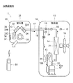
最初に、空気調和機本体1について説明する。図1、2に示した構成のものを空気調和機本体1の第1実施形態とする。
First, the
空気調和機本体1はセパレート型と呼ばれるタイプのものであり、室外機10と室内機30により構成される。
The
室外機10は、板金製部品と合成樹脂製部品により構成される筐体11の内部に、圧縮機12、切替弁13、室外側熱交換器14、膨張弁15、室外側送風機16などを収納している。切替弁13は四方弁である。膨張弁15には開度制御の可能なものが用いられる。室外側送風機はモータにプロペラファンを組み合わせたものである。
The
室外機10は2本の冷媒配管17、18で室内機30に接続される。冷媒配管17は液体の冷媒を流すことを目的としており、冷媒配管18に比較して細い管が用いられている。そのため冷媒配管17は「液管」「細管」などと称されることがある。冷媒配管18は気体の冷媒を流すことを目的としており、冷媒配管17に比較して太い管が用いられている。そのため冷媒配管18は「ガス管」「太管」などと称されることがある。冷媒には例えばHFC系のH410aやR32等が用いられる。
The
室外機10の内部の冷媒配管で、冷媒配管17に接続される冷媒配管には二方弁19が
設けられ、冷媒配管18に接続される冷媒配管には三方弁20が設けられる。二方弁19と三方弁20は、室外機10から冷媒配管17、18が取り外されるときに閉じられ、室外機10から外部に冷媒が漏れることを防ぐ。室外機10から、あるいは室内機30を含めた冷凍サイクル全体から、冷媒を放出する必要があるときは、三方弁20を通じて放出が行われる。
In the refrigerant pipe inside the
室内機30は、合成樹脂製部品により構成される筐体31の内部に、室内側熱交換器32、室内側送風機33などを収納している。室内側熱交換器32は、3個の熱交換器32A、32B、32Cを、室内側送風機33を覆う屋根のように組み合わせたものである。室内側送風機33はモータにクロスフローファンを組み合わせたものである。
The
室外側熱交換器14及び室内側熱交換器32としては、パラレルフロー型、フィンアンドチューブ型、サーペンタイン型など、様々なタイプの熱交換器が使用可能である。それらを組み合わせたタイプのものも使用できる。
As the
空気調和機本体1の運転制御を行う上で、各所の温度を知ることが不可欠である。この目的のため、室外機10と室内機30に温度検出器が配置される。室外機10においては、室外側熱交換器14に温度検出器21が配置され、圧縮機12の吐出部となる吐出管12aに温度検出器22が配置され、圧縮機12の吸入部となる吸入管12bに温度検出器23が配置され、膨張弁15と二方弁19の間の冷媒配管に温度検出器24が配置され、筐体11の内部の所定箇所に外気温測定用の温度検出器25が配置される。温度検出器21、22、23、24、25はいずれもサーミスタにより構成される。
In order to control the operation of the air conditioner
室内機30においては、室内側熱交換器32に温度検出器34が配置され、筐体31の内部の所定箇所に室内温度測定用の温度検出器35が配置される。温度検出器34、35はいずれもサーミスタにより構成される。
In the
室内機30は告知部36及び送受信部37を備える。告知部36は表示部を兼ねるものであり、情報を表示または音で告知する。告知に表示を用いる場合、告知部36は筐体31の正面に露出する形で配置される。この場合の告知部36は液晶パネルやLEDで表示を行う。告知が専ら音により行われる場合は、告知部36は筐体31の内部に隠れていてもよい。送受信部37はリモコン50からの信号を受信したり、リモコン50に対し信号を送信したりするためのものであり、送受信のための素子を筐体31の正面に露出させている。
The
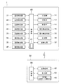
空気調和機本体1の全体制御を司るのは図3に示す制御部40である。制御部40は中央処理装置(CPU)を中心的構成要素として含むものであり、室内機30の側に配置されている。制御部40は室内温度が使用者によって設定された目標値に達するように制御を行う。
A
制御部40は不揮発性メモリ41(例えばEEPROMやフラッシュメモリ)を有する。不揮発性メモリ41はその時点で設定された空気調和機本体1の制御モードを記憶する。
The
制御部40は圧縮機12、切替弁13、膨張弁15、室外側送風機16、室内側送風機33、告知部36、及び送受信部37に対し動作指令を発する。また制御部40は温度検出器21〜25、及び温度検出器34、35からそれぞれの測定温度の出力信号を受け取り、送受信部37からはリモコン50が送信した信号を受け取る。制御部40は温度検出器21〜25及び温度検出器34、35からの出力信号を参照しつつ、圧縮機12、室外側送風機16、及び室内側送風機33に対し運転指令を発し、切替弁13と膨張弁15に
対しては状態切り替えの指令を発する。
The
図1は空気調和機本体1が冷房運転あるいは除霜運転を行っている状態を示す。この時圧縮機12は冷房時循環、すなわち圧縮機12から吐出された冷媒が先に室外側熱交換器14に入る循環様式で冷媒を循環させる。
FIG. 1 shows a state in which the
圧縮機12から吐出された高温高圧の冷媒は室外側熱交換器14に入り、そこで室外空気との熱交換が行われる。冷媒は室外空気に対し放熱を行い、凝縮する。凝縮して液状となった冷媒は室外側熱交換器14から膨張弁15に入り、そこで減圧される。減圧後の冷媒は室内側熱交換器32に送られ、膨張して低温低圧となり、室内側熱交換器32の表面温度を下げる。表面温度の下がった室内側熱交換器32は室内空気から吸熱し、これにより室内空気は冷やされる。吸熱後、低温の気体状の冷媒は圧縮機12に戻る。室外側送風機16によって生成された気流が室外側熱交換器14からの放熱を促進し、室内側送風機33によって生成された気流が室内側熱交換器32の吸熱を促進する。
The high-temperature and high-pressure refrigerant discharged from the
図2は空気調和機本体1が暖房運転を行っている状態を示す。この時は切替弁13が切り替えられて冷房運転時と冷媒の流れが逆になる。圧縮機12は暖房時循環、すなわち圧縮機12から吐出された冷媒が先に室内側熱交換器32に入る循環様式で冷媒を循環させる。
FIG. 2 shows a state in which the
圧縮機12から吐出された高温高圧の冷媒は室内側熱交換器32に入り、そこで室内空気との熱交換が行われる。冷媒は室内空気に対し放熱を行い、室内空気は暖められる。放熱し、凝縮して液状となった冷媒は室内側熱交換器32から膨張弁15に入り、そこで減圧される。減圧後の冷媒は室外側熱交換器14に送られ、膨張して低温低圧となり、室外側熱交換器14の表面温度を下げる。表面温度の下がった室外側熱交換器14は室外空気から吸熱する。吸熱後、低温の気体状の冷媒は圧縮機12に戻る。室外側送風機33によって生成された気流が室内側熱交換器33からの放熱を促進し、室外側送風機16によって生成された気流が室外側熱交換器14による吸熱を促進する。
The high-temperature and high-pressure refrigerant discharged from the
続いてリモコン50の構成について説明する。リモコン50は、中央処理装置(CPU)を中心的構成要素として含む制御部60と、制御部60に接続された送受信部61、表示部52、及び操作部53を有している。送受信部61は室内機30の送受信部37との間で赤外線その他の通信手段により双方向通信を行う。
Next, the configuration of the
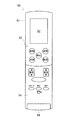
図4にリモコン50の実施形態を示す。リモコン50は片手で握れる細長い筐体51を有する。以下の説明では、図4で上になっている側を「上」、下になっている側を「下」、左になっている側を「左」、右になっている側を「右」と方位を割り当てる。
FIG. 4 shows an embodiment of the
筐体51の表面は、上部が表示部52、下部が操作部53と区分されている。表示部52は上下に長い矩形を呈しており、液晶パネルなどの表示要素と、それを覆う保護レンズにより構成される。
The surface of the
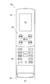
操作部53には、蓋54で覆われる部分と、蓋54で覆われない部分がある。蓋54はヒンジ部55で筐体51に連結され、ヒンジ部55を支点として開閉する。操作部53には、蓋54より上の部分、蓋54の表面、及び蓋54によって覆われる部分の3箇所に、各種操作ボタンやインジケータランプが分散して配置される。蓋54より上の部分と蓋54の表面には日常多用する操作ボタンが並び、蓋54によって覆われる部分には使用頻度の低い操作ボタンが並ぶ。以下、どの箇所に何が配置されているかにつき、概要を説明する。
The
蓋54より上の部分には、表示部52の下の箇所に、「自動」「冷房」「暖房」「除湿」という4通りの運転モードを選択するための4個の操作ボタンと、運転を停止させる停止ボタンが配置されている。
In the portion above the
蓋54の表面には、湿度上下ボタンと温度上下ボタンの他、「お知らせ」「換気」「人集中」などの操作ボタンが配置されている。
On the surface of the
蓋54で覆われる箇所には、図5に示す通り、「上下風向」「左右風向」「風量」「表示」「入タイマー」「切タイマー」「すすむ」「もどる」「予約」「リセット」の操作ボタンが配置されている。 As shown in FIG. 5, “up / down wind direction”, “left / right wind direction”, “air volume”, “display”, “on timer”, “off timer”, “sume”, “return”, “reservation”, “reset” Operation buttons are arranged.
リモコン50の操作ボタンを押すことにより、空気調和機本体1を各種制御モードで運転することができる。リモコン50は室内機30の送受信部37から情報を受信して表示部52に表示する。
By pressing the operation button of the
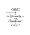
前述の通り、空気調和機本体1は各種の制御モードで運転されるが、その制御モードには「告知モード」が含まれる。「告知モード」とは、室内温度が所定値以上であるとき、そのことを告知部36が告知するモードのことである。告知モードでは図6に示すフローチャートに従って制御が進行する。
As described above, the
リモコン50の操作部53の中で「表示」の操作ボタン56が告知モードの有効、無効を切り替える切替ボタンとされている。すなわち操作部53が告知モードの有効、無効を設定する告知モード設定部ということになる。
The “display”
現在の設定が「告知モード無効」である場合、操作ボタン56を押すと、室内機30に対し「告知モードを有効にせよ」との指令が送信される。その指令を受け取った制御部40は告知モードを有効にする。告知モードが有効と設定されたことは不揮発性メモリ41に書き込まれ、不揮発性メモリ41はその情報を記憶する。告知部36が表示で告知を行うものであれば、告知部36に告知モードが有効と設定された旨の表示が現れる。告知部36が音で告知を行うものであれば、告知部36は告知モードが有効と設定されたことを音で告知する。リモコン50の表示部52にも告知モードが有効と設定された旨の表示が現れるようにしてもよい。
When the current setting is “notification mode disabled”, when the
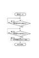
告知モードが有効に設定された場合、制御部40は、図6のステップ#101で、温度検出器35の出力をチェックし、室内温度が所定値(例えば32℃)以上であるか、どうかを調べる。調べた結果、判定がYESであればステップ#102に進む。
When the notification mode is set to be valid, the
ステップ#102では告知処理ステータスが「告知」とされる。これにより告知部36は、表示または音により、室内温度が所定値以上であること、すなわちこのまま放置すると熱中症発症のおそれがあることを、液晶パネルの表示やLEDの点灯などで使用者に告知する。これを判断の一助として使用者は、空気調和機本体1の冷房運転、あるいは除湿運転を開始するか、どうかを決定し、必要な措置をとることができる。
In
温度が高くても湿度が低ければ、温度と湿度が両方とも高い場合に比べ、熱中症発症の危険性は低減する。そのため、除湿運転も熱中症予防の有効な対策となる。 Even if the temperature is high and the humidity is low, the risk of developing heat stroke is reduced compared to the case where both the temperature and humidity are high. Therefore, dehumidifying operation is also an effective measure for preventing heat stroke.
告知が表示に加えて音でもされる構成である場合、あるいは告知が音のみでされる構成である場合、告知部36はチャイムを鳴らすなどして告知する。その場合は、所定時間毎(例えば5分毎)に音を鳴らすようにするとよい。
When the notification is configured to be sounded in addition to the display, or when the notification is configured to be sound only, the
告知モードが有効と設定されたことは不揮発性メモリ41に記憶されているので、停電があったとしても、その後復旧するとき、空気調和機本体1は告知モード有効として復旧する。停電により告知モードが無効になったということは、多くの場合使用者は気づきにくいから、知らず知らずのうちに熱中症発症のおそれのある環境に身を置く危険性が生じる。本実施形態の構成によれば、そのような危険性を、告知モードを再度有効に設定する操作なしで回避できるから、使用者にとり便利であるとともに安全である。
Since the fact that the notification mode is set to be valid is stored in the
不揮発性メモリ41に記憶された「告知モード有効」の情報は、リモコン50の操作部53によって「告知モード無効」に切り替えられないかぎり、そのまま保持し続けられる。そして不揮発性メモリ41は空気調和機本体1の側に配置されているので、リモコン50が電池の入れ替えでリセットされ、リモコン50に記憶されていた「告知モード有効」の情報が無効になったとしても、不揮発性メモリ41の記憶内容には影響がない。従って、リモコン50のリセット後、使用者が告知モードの有効設定を再度行う必要がなく、便利である。
The “notification mode valid” information stored in the
室内温度を測定する温度検出器35を、室内機30でなくリモコン50に配置する構成も可能である。リモコン50に温度検出器35を配置した場合、室内機30よりも使用者に近い場所の室温を測定できるため、より使用者の安全に配慮した制御を行うことが可能になる。
A configuration in which the
リモコン50側の温度検出器35で測定した室温が所定値(例えば32℃)以上である場合は、リモコン50の表示部52に高温であることの表示を行わせるとともに、室内機30の告知部36でも液晶パネルの表示やLEDの点灯などによる表示を行わせる。なおリモコン50と室内機30の間の通信は、赤外線通信でなく電波通信にしておくと、リモコン50の向きにかかわらず安定した通信を行うことができるので、より好ましい。
When the room temperature measured by the
本発明の空気調和システムの第2実施形態を図7から図9に基づき説明する。第1実施形態と共通する構成要素には第1実施形態の説明で用いたのと同じ符号を付し、説明は省略する。第3実施形態以降の実施形態についても同様とする。 A second embodiment of the air conditioning system of the present invention will be described with reference to FIGS. Constituent elements common to the first embodiment are denoted by the same reference numerals used in the description of the first embodiment, and description thereof is omitted. The same applies to the third and subsequent embodiments.
第2実施形態の空気調和システムが第1実施形態に係る空気調和システムと異なっているのは、室内湿度を測定する湿度検出器42が室内機30に配置されている点である。
The air conditioning system according to the second embodiment differs from the air conditioning system according to the first embodiment in that a
第2実施形態の空気調和システムでは、告知モードが有効であるとき、図9のフローチャートに従って制御が進行する。 In the air conditioning system of the second embodiment, when the notification mode is valid, the control proceeds according to the flowchart of FIG.
制御部40は、図9のステップ#111で、湿度検出器42の出力をチェックし、室内湿度が所定値以上であるか、どうかを調べる。調べた結果、判定がYESであればステップ#112に進む。
In
制御部40は、ステップ#112では温度検出器35の出力をチェックし、室内温度が所定値以上であるか、どうかを調べる。調べた結果、判定がYESであればステップ#113に進む。
In
ステップ#113では告知処理ステータスが「告知」とされる。これにより告知部36は、表示または音により、室内湿度が所定値以上であり、室内温度も所定値以上であること、すなわちこのまま放置すると熱中症発症のおそれがあることを使用者に告知する。これを判断の一助として使用者は、空気調和機本体1の冷房運転、あるいは除湿運転を開始するか、どうかを決定し、必要な措置をとることができる。
In
第2実施形態の空気調和システムでは、室内温度だけでなく、室内湿度も考慮に入れたより細やかな告知を行うので、告知を一層正確なものとすることができる。 In the air conditioning system of the second embodiment, a more detailed notification is made in consideration of not only the room temperature but also the room humidity, so that the notification can be made more accurate.
室内温度を測定する温度検出器35と、室内湿度を測定する湿度検出器42の一方または両方を、室内機30でなくリモコン50に配置する構成も可能である。
A configuration in which one or both of the
第1実施形態においても第2実施形態においても、使用者が冷房運転や除湿運転を開始した後、告知モードは有効に働き続けている。すなわち、冷房運転や除湿運転を行っていても、室内温度や室内湿度が所定値を下回らなければ告知が続く。これにより使用者は、温度や湿度が下がるように設定を変えた方が良いことを認識しやすくなる。 In both the first embodiment and the second embodiment, the notification mode continues to work effectively after the user starts the cooling operation or the dehumidifying operation. That is, even if the cooling operation or the dehumidifying operation is performed, the notification continues unless the room temperature or the room humidity falls below a predetermined value. This makes it easier for the user to recognize that it is better to change the settings so that the temperature and humidity decrease.
上記のように、冷房運転や暖房運転などを行っていない運転開始待機状態(例えば、使用者からの運転開始指示待ちの状態)だけでなく、空調運転中も告知モードにより告知することで、常に使用者の注意を喚起し、熱中症を回避しやすくすることができる。 As mentioned above, not only the operation start standby state (for example, the state of waiting for the operation start instruction from the user) in which the cooling operation or the heating operation is not performed, but also the notification mode during the air conditioning operation, It can alert the user and make it easier to avoid heat stroke.
本発明の空気調和システムの第3実施形態を図10から図12に基づき説明する。第3実施形態は第2実施形態に次の構成要素を加えたものである。それは人体感知センサ43である。人体感知センサ43は室内機30に配置されている。
A third embodiment of the air conditioning system of the present invention will be described with reference to FIGS. The third embodiment is obtained by adding the following components to the second embodiment. It is a
第3実施形態では、図9のフローチャートの制御フローを実行した後、図12のフローチャートに従って制御が進行する。 In the third embodiment, after executing the control flow of the flowchart of FIG. 9, the control proceeds according to the flowchart of FIG.
制御部40は、図12のステップ#121で、室内湿度が所定値以上であり、室内温度も所定値以上である旨の告知が、所定時間以上継続しているかどうかを調べる。調べた結果、判定がYESであれば、ステップ#122に進む。
In
制御部40は、ステップ#122では人体感知センサ43の出力をチェックし、人体感知センサ43が人体を感知しているか、どうかを調べる。調べた結果、判定がYESであればステップ#123に進む。
In
ステップ#123では運転ステータスが「冷房運転」とされる。これにより空気調和機本体1は冷房運転を自動的に開始し、熱中症発症のおそれが低減するまで室内環境を改善する。湿度が下がっただけでも室内環境は改善されるところから、自動的に開始されるのは除湿運転であることとし、室内湿度のみならず室内温度までも下げるため冷房運転に切り替えるかどうかは使用者の選択に委ねることとしてもよい。
In
第3実施形態では、空気調和領域に人がいない限り自動的に冷房運転や除湿運転を開始することはないので、無駄に電力を消費することがなく、省エネルギーを達成することができる。 In the third embodiment, the cooling operation and the dehumidifying operation are not automatically started unless there is a person in the air-conditioning region, so that power is not consumed wastefully and energy saving can be achieved.
室内温度を測定する温度検出器35、室内湿度を測定する湿度検出器42、及び人体感知センサ43のいずれかあるいはすべてを、室内機30でなくリモコン50に配置する構成も可能である。
A configuration in which any or all of the
本発明の空気調和システムの第4実施形態を図13に基づき説明する。第4実施形態がそれ以前の実施形態と異なっているのは、空気調和機本体1から告知部をなくし、リモコン50の表示部52のみに告知部としての機能を持たせた点である。
A fourth embodiment of the air conditioning system of the present invention will be described with reference to FIG. The fourth embodiment is different from the previous embodiments in that the notification unit is eliminated from the
制御部40は送受信部37よりリモコン50の送受信部61に必要な情報を送信する。情報を受信したリモコン50は、表示部52で表示により告知を行う。表示に加え、音で
告知を行うこととしてもよい。また、リモコン50は手で持ったり、テーブルの上に置いたりするものであるところから、表示や音に加えて、あるいはそれらに代えて、振動で告知を行うこととしてもよい。
The
第4実施形態に、第2実施形態の湿度検出器や、第3実施形態の人体感知センサといった構成要素を追加することも可能である。また、室内温度を測定する温度検出器35も含め、それらの構成要素のいずれかあるいはすべてを、室内機30でなくリモコン50に配置する構成も可能である。
Components such as the humidity detector of the second embodiment and the human body sensor of the third embodiment can be added to the fourth embodiment. Moreover, the structure which arrange | positions one or all of those components including the
また、室内機30に告知部を復活し、リモコン50と室内機30の両方で告知を行うようにしてもよい。
Further, the notification unit may be restored to the
温度検出器、湿度検出器、人体感知センサなどの配置箇所を、室内機30とリモコン50の一方に限定する必要もない。室内機30とリモコン50の両方に設け、どちらかで告知条件が満たされたら告知が行われるようにしてもよい。
It is not necessary to limit the arrangement location of the temperature detector, the humidity detector, the human body sensor, etc. to one of the
第1から第4までのすべての実施形態で、一般的なリモートコントローラ50を遠隔操作装置として使用したが、無線通信機能(赤外線通信や電波通信)を備えた機器であれば、空気清浄機や加湿器などの機器であっても遠隔操作装置として使用することができる。
In all the first to fourth embodiments, the general
空気清浄機や加湿器に、室内温度を計測する温度検出器、室内湿度を計測する湿度検出器、人体感知センサなどを配置しておけば、それらは空気調和機の室内機よりも低い位置で検出を行うため、使用者の生活空間に近い位置で室温や湿度(相対湿度)を検出することができ、使用者が実感する環境により即した制御を行うことができる。この場合の告知も、空気清浄機や加湿器の側からのみ行うようにしてもよく、空気調和機本体の側からのみ行うようにしてもよく、両方から行うようにしてもよい。 If a temperature detector that measures the room temperature, a humidity detector that measures the room humidity, a human body sensor, etc. are installed in the air purifier or humidifier, they are located at a position lower than the indoor unit of the air conditioner. Since detection is performed, room temperature and humidity (relative humidity) can be detected at a position close to the user's living space, and control in accordance with the environment that the user feels can be performed. The notification in this case may be performed only from the side of the air cleaner or humidifier, may be performed only from the side of the air conditioner body, or may be performed from both sides.
携帯電話やスマートフォンなど、無線で情報を授受する携帯情報端末に専用のアプリケーションをインストールし、これらを遠隔操作装置として使用することも可能である。これらの機器であれば、表示はもちろんのこと、音や振動で告知を行うことも容易である。これらの機器は、身につけたりバッグに入れるなど、使用者と共にあることが多いので、告知がより伝わりやすい。 It is also possible to install a dedicated application on a portable information terminal that transmits and receives information wirelessly, such as a mobile phone or a smartphone, and use these as a remote control device. With these devices, not only display but also notification with sound and vibration is easy. Since these devices are often worn with the user, such as being worn or put in a bag, the notification is more easily transmitted.
ポケットベルのような形の専用の告知端末を用意し、これを遠隔操作装置としてもよい。 A dedicated notification terminal shaped like a pager may be prepared and used as a remote control device.
以上、本発明の実施形態につき説明したが、本発明の範囲はこれに限定されるものではなく、発明の主旨を逸脱しない範囲で種々の変更を加えて実施することができる。 Although the embodiments of the present invention have been described above, the scope of the present invention is not limited to these embodiments, and various modifications can be made without departing from the spirit of the invention.
本発明は空気調和システムに広く利用可能である。 The present invention is widely applicable to air conditioning systems.
1 空気調和機本体
10 室外機
30 室内機
35 温度検出器
36 告知部
40 制御部
41 不揮発性メモリ
42 湿度検出器
43 人体感知センサ
50 リモートコントローラ
52 表示部(告知部)
53 操作部(告知モード設定部)
60 制御部
DESCRIPTION OF
53 Operation part (notification mode setting part)
60 Control unit
Claims (4)
空気調和運転を行う空気調和機本体と、
前記空気調和機本体を遠隔操作することができる遠隔操作装置と、
前記空気調和機システムの制御を行う制御部と、
室内温度を検出する温度検出器と、
音により運転開始を促す告知部と、を備え、
前記遠隔操作装置は、
前記告知部に、音で告知させることを有効にする有効モードと、
前記告知部に、音で告知させることを無効にする無効モードのいずれかを設定することができる設定部を有し、
前記制御部は、前記設定部で設定されたモードが前記有効モードであるとき、前記温度検出器で測定された室内温度が所定値以上の高温である場合に、前記告知部に音で告知させ、
前記告知は、冷房運転または除湿運転が開始された後も、前記室内温度が所定値を下回らない間は継続して行われる
ことを特徴とする空気調和システム。 An air conditioning system capable of dehumidifying operation or cooling operation,
An air conditioner body that performs air conditioning operation,
A remote operation device capable of remotely operating the air conditioner body;
A control unit for controlling the air conditioner system;
A temperature detector for detecting the room temperature;
A notification section that prompts driving start by sound,
The remote control device is:
An effective mode for enabling the notification unit to notify by sound; and
The notification unit has a setting unit that can set any one of invalid modes for disabling sound notification.
When the mode set by the setting unit is the effective mode and the room temperature measured by the temperature detector is higher than a predetermined value, the control unit causes the notification unit to make a sound notification. ,
The air conditioning system is characterized in that the notification is continuously performed after the cooling operation or the dehumidifying operation is started as long as the indoor temperature does not fall below a predetermined value.
空気調和運転を行う空気調和機本体と、
前記空気調和機本体を遠隔操作することができる遠隔操作装置と、
前記空気調和機システムの制御を行う制御部と、
室内温度を検出する温度検出器と、
室内湿度を検出する湿度検出器と、
音により運転開始を促す告知部と、を備え、
前記遠隔操作装置は、
前記告知部に、音で告知させることを有効にする有効モードと、
前記告知部に、音で告知させることを無効にする無効モードのいずれかを設定することが
できる設定部を有し、
前記制御部は、前記設定部で設定されたモードが前記有効モードであるとき、前記温度検出器で測定された室内温度が所定値以上の高温で、かつ、前記湿度検出器で測定された室内湿度が所定値以上の高湿である場合に、前記告知部に音で告知させ、
前記告知は、冷房運転または除湿運転が開始された後も、前記室内温度と前記室内湿度とがそれぞれに定められた所定値を下回らない間は継続して行われる
ことを特徴とする空気調和システム。 An air conditioning system capable of dehumidifying operation or cooling operation,
An air conditioner body that performs air conditioning operation,
A remote operation device capable of remotely operating the air conditioner body;
A control unit for controlling the air conditioner system;
A temperature detector for detecting the room temperature;
A humidity detector for detecting indoor humidity;
A notification section that prompts driving start by sound,
The remote control device is:
An effective mode for enabling the notification unit to notify by sound; and
The notification unit has a setting unit that can set any one of invalid modes for disabling sound notification.
When the mode set by the setting unit is the effective mode, the control unit has a room temperature measured by the temperature detector that is higher than a predetermined value and is measured by the humidity detector. When the humidity is high or higher than the predetermined value, let the notification unit notify with sound,
The air conditioning system is characterized in that the notification is continuously performed after the cooling operation or the dehumidifying operation is started as long as the indoor temperature and the indoor humidity do not fall below predetermined values. .
前記蓋を開けたとき前記設定部を操作することが可能となることを特徴とする請求項3に記載の空気調和システム。 The remote control device has a lid that can be opened and closed to cover the setting unit,
The air conditioning system according to claim 3, wherein the setting unit can be operated when the lid is opened.
Priority Applications (1)
| Application Number | Priority Date | Filing Date | Title |
|---|---|---|---|
| JP2015212704A JP6068595B2 (en) | 2015-10-29 | 2015-10-29 | Air conditioner |
Applications Claiming Priority (1)
| Application Number | Priority Date | Filing Date | Title |
|---|---|---|---|
| JP2015212704A JP6068595B2 (en) | 2015-10-29 | 2015-10-29 | Air conditioner |
Related Parent Applications (1)
| Application Number | Title | Priority Date | Filing Date |
|---|---|---|---|
| JP2015128422A Division JP6059769B2 (en) | 2015-06-26 | 2015-06-26 | Air conditioner |
Related Child Applications (1)
| Application Number | Title | Priority Date | Filing Date |
|---|---|---|---|
| JP2016219516A Division JP6306129B2 (en) | 2016-11-10 | 2016-11-10 | Air conditioning system |
Publications (3)
| Publication Number | Publication Date |
|---|---|
| JP2016014527A JP2016014527A (en) | 2016-01-28 |
| JP2016014527A5 JP2016014527A5 (en) | 2016-06-23 |
| JP6068595B2 true JP6068595B2 (en) | 2017-01-25 |
Family
ID=55230839
Family Applications (1)
| Application Number | Title | Priority Date | Filing Date |
|---|---|---|---|
| JP2015212704A Active JP6068595B2 (en) | 2015-10-29 | 2015-10-29 | Air conditioner |
Country Status (1)
| Country | Link |
|---|---|
| JP (1) | JP6068595B2 (en) |
Cited By (1)
| Publication number | Priority date | Publication date | Assignee | Title |
|---|---|---|---|---|
| CN107270475A (en) * | 2017-06-14 | 2017-10-20 | 青岛海尔空调电子有限公司 | The autonomous dormancy control method of air-conditioner outdoor unit and device |
Family Cites Families (9)
| Publication number | Priority date | Publication date | Assignee | Title |
|---|---|---|---|---|
| JP2003106904A (en) * | 2001-09-28 | 2003-04-09 | Pigeon Corp | Temperature/humidity meter and warning display method therefor |
| JP2004020164A (en) * | 2002-06-20 | 2004-01-22 | Daikin Ind Ltd | Air conditioning machine and system |
| JP2004003864A (en) * | 2003-08-08 | 2004-01-08 | Sharp Corp | Air conditioner |
| JP2008119198A (en) * | 2006-11-10 | 2008-05-29 | Tokai Rika Co Ltd | Advice device for improving situation |
| JP5578463B2 (en) * | 2009-05-14 | 2014-08-27 | 静岡県 | Wet bulb temperature and WBGT prediction method, WBGT meter, and heat stroke risk determination device |
| JP5489910B2 (en) * | 2010-08-10 | 2014-05-14 | 三菱電機株式会社 | Air conditioner alarm device and air conditioner |
| JP2012207867A (en) * | 2011-03-30 | 2012-10-25 | Hitachi Appliances Inc | Air conditioning control system |
| JP5749612B2 (en) * | 2011-09-22 | 2015-07-15 | ミサワホーム株式会社 | Indoor environment adjustment system |
| JP5950610B2 (en) * | 2012-02-16 | 2016-07-13 | 三菱電機株式会社 | Air conditioner |
-
2015
- 2015-10-29 JP JP2015212704A patent/JP6068595B2/en active Active
Cited By (2)
| Publication number | Priority date | Publication date | Assignee | Title |
|---|---|---|---|---|
| CN107270475A (en) * | 2017-06-14 | 2017-10-20 | 青岛海尔空调电子有限公司 | The autonomous dormancy control method of air-conditioner outdoor unit and device |
| CN107270475B (en) * | 2017-06-14 | 2020-05-19 | 青岛海尔空调电子有限公司 | Autonomous dormancy control method and device for outdoor unit of air conditioner |
Also Published As
| Publication number | Publication date |
|---|---|
| JP2016014527A (en) | 2016-01-28 |
Similar Documents
| Publication | Publication Date | Title |
|---|---|---|
| JP6055193B2 (en) | Air conditioning system | |
| JP6261295B2 (en) | Air conditioning system | |
| KR102206459B1 (en) | An Air-Conditioner AND A Controlling Method | |
| JPWO2013172279A1 (en) | Air conditioner and air conditioning system | |
| KR102262245B1 (en) | Air conditioner and method for control of air conditioner | |
| JP5996989B2 (en) | Air conditioner | |
| JP7403669B2 (en) | Ventilation alarm device and ventilation alarm program | |
| JP2007155261A (en) | Air conditioner | |
| JP4835603B2 (en) | Air conditioner and safety management method for air conditioner | |
| ES2976047T3 (en) | Refrigeration cycle system | |
| ES2967657T3 (en) | Refrigerant leak notification device and refrigeration cycle system provided with refrigerant leak notification device | |
| JP2013083437A (en) | Air conditioning apparatus and safety management method for the same | |
| JP2008057837A (en) | Coolant leakage detecting method, coolant leakage detector and air conditioner | |
| JP2016023809A (en) | Air conditioner | |
| CN109073254B (en) | Air conditioner | |
| JP6068595B2 (en) | Air conditioner | |
| JP6059769B2 (en) | Air conditioner | |
| JP2015075302A (en) | Air conditioner | |
| JP6306129B2 (en) | Air conditioning system | |
| JP5020114B2 (en) | Air conditioner | |
| JP5858021B2 (en) | Air conditioner | |
| JP5017329B2 (en) | Wireless remote control device | |
| JP7522960B2 (en) | Air conditioners | |
| KR101139451B1 (en) | Air-conditioner and Controlling Method for the same | |
| KR100723947B1 (en) | Method for controlling operation of air conditioner |
Legal Events
| Date | Code | Title | Description |
|---|---|---|---|
| A621 | Written request for application examination |
Free format text: JAPANESE INTERMEDIATE CODE: A621 Effective date: 20151029 |
|
| A521 | Written amendment |
Free format text: JAPANESE INTERMEDIATE CODE: A523 Effective date: 20160428 |
|
| A871 | Explanation of circumstances concerning accelerated examination |
Free format text: JAPANESE INTERMEDIATE CODE: A871 Effective date: 20160428 |
|
| A975 | Report on accelerated examination |
Free format text: JAPANESE INTERMEDIATE CODE: A971005 Effective date: 20160530 |
|
| A131 | Notification of reasons for refusal |
Free format text: JAPANESE INTERMEDIATE CODE: A131 Effective date: 20160607 |
|
| A521 | Written amendment |
Free format text: JAPANESE INTERMEDIATE CODE: A523 Effective date: 20160804 |
|
| A02 | Decision of refusal |
Free format text: JAPANESE INTERMEDIATE CODE: A02 Effective date: 20161101 |
|
| RD02 | Notification of acceptance of power of attorney |
Free format text: JAPANESE INTERMEDIATE CODE: A7422 Effective date: 20161104 |
|
| A521 | Written amendment |
Free format text: JAPANESE INTERMEDIATE CODE: A523 Effective date: 20161110 |
|
| A911 | Transfer of reconsideration by examiner before appeal (zenchi) |
Free format text: JAPANESE INTERMEDIATE CODE: A911 Effective date: 20161117 |
|
| TRDD | Decision of grant or rejection written | ||
| A01 | Written decision to grant a patent or to grant a registration (utility model) |
Free format text: JAPANESE INTERMEDIATE CODE: A01 Effective date: 20161129 |
|
| A61 | First payment of annual fees (during grant procedure) |
Free format text: JAPANESE INTERMEDIATE CODE: A61 Effective date: 20161222 |
|
| R150 | Certificate of patent or registration of utility model |
Ref document number: 6068595 Country of ref document: JP Free format text: JAPANESE INTERMEDIATE CODE: R150 |