JP6068458B2 - Compound wheel mounting device - Google Patents
Compound wheel mounting device Download PDFInfo
- Publication number
- JP6068458B2 JP6068458B2 JP2014517324A JP2014517324A JP6068458B2 JP 6068458 B2 JP6068458 B2 JP 6068458B2 JP 2014517324 A JP2014517324 A JP 2014517324A JP 2014517324 A JP2014517324 A JP 2014517324A JP 6068458 B2 JP6068458 B2 JP 6068458B2
- Authority
- JP
- Japan
- Prior art keywords
- sleeve
- opening
- fixed
- attachment device
- mounting
- Prior art date
- Legal status (The legal status is an assumption and is not a legal conclusion. Google has not performed a legal analysis and makes no representation as to the accuracy of the status listed.)
- Active
Links
- 150000001875 compounds Chemical class 0.000 title claims description 3
- 239000002131 composite material Substances 0.000 claims description 71
- 230000000295 complement effect Effects 0.000 claims description 28
- VNWKTOKETHGBQD-UHFFFAOYSA-N methane Chemical compound C VNWKTOKETHGBQD-UHFFFAOYSA-N 0.000 claims description 11
- 229920000049 Carbon (fiber) Polymers 0.000 claims description 10
- 239000004917 carbon fiber Substances 0.000 claims description 10
- 210000000078 claw Anatomy 0.000 claims description 2
- 230000001788 irregular Effects 0.000 claims description 2
- 239000000835 fiber Substances 0.000 description 6
- 239000000463 material Substances 0.000 description 5
- 230000006378 damage Effects 0.000 description 4
- OKTJSMMVPCPJKN-UHFFFAOYSA-N Carbon Chemical compound [C] OKTJSMMVPCPJKN-UHFFFAOYSA-N 0.000 description 2
- 229910052799 carbon Inorganic materials 0.000 description 2
- 230000008878 coupling Effects 0.000 description 2
- 238000010168 coupling process Methods 0.000 description 2
- 238000005859 coupling reaction Methods 0.000 description 2
- 239000002184 metal Substances 0.000 description 2
- 230000036316 preload Effects 0.000 description 2
- 239000004593 Epoxy Substances 0.000 description 1
- 239000000853 adhesive Substances 0.000 description 1
- 230000001070 adhesive effect Effects 0.000 description 1
- 230000004323 axial length Effects 0.000 description 1
- 230000008901 benefit Effects 0.000 description 1
- 230000005540 biological transmission Effects 0.000 description 1
- 230000006835 compression Effects 0.000 description 1
- 238000007906 compression Methods 0.000 description 1
- 230000032798 delamination Effects 0.000 description 1
- 239000003822 epoxy resin Substances 0.000 description 1
- 239000003733 fiber-reinforced composite Substances 0.000 description 1
- 238000009434 installation Methods 0.000 description 1
- 238000000034 method Methods 0.000 description 1
- 238000012986 modification Methods 0.000 description 1
- 230000004048 modification Effects 0.000 description 1
- 229920000647 polyepoxide Polymers 0.000 description 1
- 230000008569 process Effects 0.000 description 1
- -1 structure Substances 0.000 description 1
- 230000003313 weakening effect Effects 0.000 description 1
Images


Classifications
-
- B—PERFORMING OPERATIONS; TRANSPORTING
- B60—VEHICLES IN GENERAL
- B60B—VEHICLE WHEELS; CASTORS; AXLES FOR WHEELS OR CASTORS; INCREASING WHEEL ADHESION
- B60B3/00—Disc wheels, i.e. wheels with load-supporting disc body
- B60B3/14—Attaching disc body to hub ; Wheel adapters
- B60B3/145—Attaching disc body to hub ; Wheel adapters using washers or distance bushes
-
- B—PERFORMING OPERATIONS; TRANSPORTING
- B60—VEHICLES IN GENERAL
- B60B—VEHICLE WHEELS; CASTORS; AXLES FOR WHEELS OR CASTORS; INCREASING WHEEL ADHESION
- B60B3/00—Disc wheels, i.e. wheels with load-supporting disc body
- B60B3/14—Attaching disc body to hub ; Wheel adapters
- B60B3/147—Attaching disc body to hub ; Wheel adapters using wheel adapters
-
- B—PERFORMING OPERATIONS; TRANSPORTING
- B60—VEHICLES IN GENERAL
- B60B—VEHICLE WHEELS; CASTORS; AXLES FOR WHEELS OR CASTORS; INCREASING WHEEL ADHESION
- B60B3/00—Disc wheels, i.e. wheels with load-supporting disc body
- B60B3/14—Attaching disc body to hub ; Wheel adapters
- B60B3/16—Attaching disc body to hub ; Wheel adapters by bolts or the like
-
- B—PERFORMING OPERATIONS; TRANSPORTING
- B60—VEHICLES IN GENERAL
- B60B—VEHICLE WHEELS; CASTORS; AXLES FOR WHEELS OR CASTORS; INCREASING WHEEL ADHESION
- B60B5/00—Wheels, spokes, disc bodies, rims, hubs, wholly or predominantly made of non-metallic material
- B60B5/02—Wheels, spokes, disc bodies, rims, hubs, wholly or predominantly made of non-metallic material made of synthetic material
-
- F—MECHANICAL ENGINEERING; LIGHTING; HEATING; WEAPONS; BLASTING
- F16—ENGINEERING ELEMENTS AND UNITS; GENERAL MEASURES FOR PRODUCING AND MAINTAINING EFFECTIVE FUNCTIONING OF MACHINES OR INSTALLATIONS; THERMAL INSULATION IN GENERAL
- F16B—DEVICES FOR FASTENING OR SECURING CONSTRUCTIONAL ELEMENTS OR MACHINE PARTS TOGETHER, e.g. NAILS, BOLTS, CIRCLIPS, CLAMPS, CLIPS OR WEDGES; JOINTS OR JOINTING
- F16B43/00—Washers or equivalent devices; Other devices for supporting bolt-heads or nuts
-
- B—PERFORMING OPERATIONS; TRANSPORTING
- B60—VEHICLES IN GENERAL
- B60B—VEHICLE WHEELS; CASTORS; AXLES FOR WHEELS OR CASTORS; INCREASING WHEEL ADHESION
- B60B2360/00—Materials; Physical forms thereof
- B60B2360/30—Synthetic materials
- B60B2360/36—Composite materials
-
- B—PERFORMING OPERATIONS; TRANSPORTING
- B60—VEHICLES IN GENERAL
- B60B—VEHICLE WHEELS; CASTORS; AXLES FOR WHEELS OR CASTORS; INCREASING WHEEL ADHESION
- B60B27/00—Hubs
- B60B27/0047—Hubs characterised by functional integration of other elements
- B60B27/0052—Hubs characterised by functional integration of other elements the element being a brake disc
-
- B—PERFORMING OPERATIONS; TRANSPORTING
- B60—VEHICLES IN GENERAL
- B60B—VEHICLE WHEELS; CASTORS; AXLES FOR WHEELS OR CASTORS; INCREASING WHEEL ADHESION
- B60B2900/00—Purpose of invention
- B60B2900/20—Avoidance of
- B60B2900/212—Damage
-
- B—PERFORMING OPERATIONS; TRANSPORTING
- B60—VEHICLES IN GENERAL
- B60B—VEHICLE WHEELS; CASTORS; AXLES FOR WHEELS OR CASTORS; INCREASING WHEEL ADHESION
- B60B2900/00—Purpose of invention
- B60B2900/30—Increase in
- B60B2900/325—Reliability
-
- F—MECHANICAL ENGINEERING; LIGHTING; HEATING; WEAPONS; BLASTING
- F16—ENGINEERING ELEMENTS AND UNITS; GENERAL MEASURES FOR PRODUCING AND MAINTAINING EFFECTIVE FUNCTIONING OF MACHINES OR INSTALLATIONS; THERMAL INSULATION IN GENERAL
- F16B—DEVICES FOR FASTENING OR SECURING CONSTRUCTIONAL ELEMENTS OR MACHINE PARTS TOGETHER, e.g. NAILS, BOLTS, CIRCLIPS, CLAMPS, CLIPS OR WEDGES; JOINTS OR JOINTING
- F16B19/00—Bolts without screw-thread; Pins, including deformable elements; Rivets
- F16B19/02—Bolts or sleeves for positioning of machine parts, e.g. notched taper pins, fitting pins, sleeves, eccentric positioning rings
Landscapes
- Engineering & Computer Science (AREA)
- Mechanical Engineering (AREA)
- General Engineering & Computer Science (AREA)
- Chemical & Material Sciences (AREA)
- Materials Engineering (AREA)
- Connection Of Plates (AREA)
- Mutual Connection Of Rods And Tubes (AREA)
- Clamps And Clips (AREA)
- Bolts, Nuts, And Washers (AREA)
Description
本発明は、概して、1以上の複合ホイールをマウントに取り付けるための装置に関する。本発明は、特に、カーボンファイバホイールの取付装置に適しており、本文以下、本発明をこの例示的な用途に関して開示することが好都合であろう。 The present invention generally relates to an apparatus for attaching one or more composite wheels to a mount. The present invention is particularly suitable for carbon fiber wheel mounting devices, and it will be advantageous to disclose the present invention with respect to this exemplary application hereinafter.
本発明の背景に関する以下の論議は、本発明の理解を容易にすることを意図したものである。しかし、この論議が、引用された材料のいずれも、本出願の優先日の時点で、公開された、公知の、又は一般常識の一部であったことを認証又は承認するものではないことを理解されたい。 The following discussion regarding the background of the invention is intended to facilitate an understanding of the invention. However, this discussion does not certify or approve that any of the cited materials were public, known or part of common sense as of the priority date of this application. I want you to understand.
複合構造物をその他の部品又は構造物に取り付けることは困難な課題であろう。複合構造物、例えばカーボンファイバ部品は、一般に、繊維方向において非常に硬いが、繊維方向に対して垂直な方向においては、より低強度である。ボルトジョイント連結のための取付穴は、一般に、繊維方向に対して垂直に形成される。従って、このような取付穴を通して形成されるジョイントに加えられる押圧荷重は繊維に対して垂直になり、繊維に対して平行ではない。材料の、繊維に対して垂直方向の硬さは非常に低い。 Attaching the composite structure to other parts or structures can be a difficult task. Composite structures, such as carbon fiber parts, are generally very hard in the fiber direction, but have lower strength in the direction perpendicular to the fiber direction. The mounting hole for connecting the bolt joint is generally formed perpendicular to the fiber direction. Accordingly, the pressing load applied to the joint formed through such mounting holes is perpendicular to the fiber and not parallel to the fiber. The hardness of the material in the direction perpendicular to the fibers is very low.
従って、ボルト/ワッシャのヘッドと、このヘッドが連結されるマウントとの間に必要なのは、損傷を回避するための低いクランプ圧力(締め付け圧)である。高いクランプ圧力は、複合材料を、予め形成された取付穴で、又はそのすぐ近傍で損傷する場合があり、これが、この取付穴の縁で、又はそのすぐ近傍での剥離を生じさせる。これが、慣用の取付装置及び固定装置との堅固なジョイントの達成を困難にする。 Therefore, what is needed between the bolt / washer head and the mount to which the head is connected is a low clamping pressure to avoid damage. The high clamping pressure can damage the composite material at or near the preformed mounting hole, which causes delamination at or near the edge of the mounting hole. This makes it difficult to achieve a rigid joint with conventional mounting and fastening devices.
荷重をより大きい領域にわたって分配するためにワッシャを用いることが可能である。しかし、慣用のフラットワッシャは、荷重を取付開口周囲で不均一に分配する。多くの場合、荷重は、ボルトのヘッドにより近い領域においてより大きく、従って、不都合な高押圧ゾーンを取付穴の縁近傍に生じる。 A washer can be used to distribute the load over a larger area. However, conventional flat washers distribute the load unevenly around the mounting opening. In many cases, the load is greater in the region closer to the bolt head, thus creating an inconvenient high press zone near the edge of the mounting hole.
従って、特別な固定具の組合せが、複合構造物のために用いられ得る。しかし、多くの先行技術のボルト‐ナットの組合せは、ボルト及びナットが用いられる取付穴にて、又はこの取付穴近傍で複合構造物に荷重を加える形状寸法を有し、従って、複合材料のこの領域における弱化、破損、又は破壊の原因となる。 Thus, special fixture combinations can be used for composite structures. However, many prior art bolt-nut combinations have geometries that load the composite structure at or near the mounting holes in which the bolts and nuts are used, and thus this of the composite material. Cause weakening, breakage or destruction in the area.
従って、複合ホイールのための、上記の欠点の1以上を克服する取付装置を提供することが望ましいであろう。 Accordingly, it would be desirable to provide an attachment device for a composite wheel that overcomes one or more of the above-mentioned drawbacks.
本発明は、少なくとも1つの複合ホイールを、細長い固定具部材と、該細長い固定具部材に締結可能な固定ナットとを用いてマウントに取り付けるために用いる取付装置を提供する。前記取付装置を、前記細長い固定具部材が挿入される少なくとも1つの取付開口を備える複合ホイールと共に用いることができることが想定される。前記取付装置は、前記細長い固定具部材が使用時に挿入されることが可能な固定開口を有する固定ワッシャを有する。前記固定開口は、半径方向の中央に固定軸を有する。前記固定ワッシャは、また、前記複合ホイールの、前記取付開口周囲の表面に面するように構成されたベースも有する。 The present invention provides an attachment device for use in attaching at least one composite wheel to a mount using an elongate fastener member and a fastening nut that can be fastened to the elongate fixture member. It is envisioned that the attachment device can be used with a composite wheel that includes at least one attachment opening into which the elongated fastener member is inserted. The attachment device includes a fixed washer having a fixed opening through which the elongated fastener member can be inserted during use. The fixed opening has a fixed shaft in the center in the radial direction. The fixed washer also has a base configured to face a surface of the composite wheel around the mounting opening.
さらに、前記固定ワッシャは、略軸方向に、前記取付開口から外側に向いた固定側部を有する。前記固定側部は、前記固定ナットが前記細長い固定具部材に組み付けられるときに前記固定ナットの相補的部分と係合するように構成された少なくとも1つの係合面を有する。前記取付装置は、また、スリーブを有し、該スリーブは、前記固定開口の周囲の前記ベースから外側に向けて前記固定軸に対して軸方向に延びる。前記スリーブは、前記複合ホイールの取付開口内に延びるように構成されている。前記スリーブは、また、前記マウント内又は該マウントの近傍に配置された部材内に設けられた相補的形状の前記スリーブ開口に収容されるように構成された遠位端を有する。 Further, the fixed washer has a fixed side portion facing outward from the mounting opening in a substantially axial direction. The stationary side has at least one engagement surface configured to engage a complementary portion of the locking nut when the locking nut is assembled to the elongated fastener member. The attachment device also includes a sleeve that extends axially relative to the fixed shaft outwardly from the base around the fixed opening. The sleeve is configured to extend into the mounting opening of the composite wheel. The sleeve also has a distal end configured to be received in a complementary shaped sleeve opening provided in the mount or in a member disposed in the vicinity of the mount.
本発明の取付装置は、前記複合ホイールが、前記マウントに、前記複合ホイールを損傷せずに前記固定ナットに対して非常に堅固に固定されることを可能にする。これにより、前記取付装置における何らかの外部荷重状況に関連する固定トルクの損失を低減し、又は実質的に排除することができる。固定トルクの損失が進行すると、ボルトジョイントが緩んで固定具を回転させる場合があり、それにより、さらなるトルク損失、及び、ジョイントのクランプ(締付け)荷重の低減を生じる。 The mounting device of the present invention allows the composite wheel to be fixed to the mount very firmly to the fixing nut without damaging the composite wheel. This can reduce or substantially eliminate the loss of fixed torque associated with any external load situation in the mounting device. As the loss of fixed torque progresses, the bolt joint may loosen and rotate the fixture, resulting in further torque loss and reduced joint clamping (clamping) load.
前記マウントが、何物かをその上又はその内部に取り付け若しくは固定し、又は、取り付け若しくは固定する支持体、バッキング(裏当て)、設置部などであることが理解できる。好ましい実施形態において、前記マウントは、前記複合ホイールのためのホイールマウント(又はホイールハブ)である。 It can be understood that the mount is a support, a backing (backing), an installation part or the like that attaches or fixes something on or inside the mount, or attaches or fixes the mount. In a preferred embodiment, the mount is a wheel mount (or wheel hub) for the composite wheel.
前記スリーブは、好ましくは、前記取付装置に高荷重が加えられたときに前記ワッシャが内側に崩壊することを防止するように設計されている。前記スリーブは、荷重を前記固定開口の中心から遠ざけるように分配するように機能する。従って、前記スリーブは、前記複合ホイールの前記取付開口内を通って延び、そして、相補的形状のスリーブ開口(前記マウント内、又は、前記マウントの近傍に設けられた部材内に配置されている)に収容されるように構成されている。幾つかの実施形態において、前記スリーブ開口は前記マウント内に形成される。その他の実施形態において、前記取付装置が、さらなる部品、例えば、スリーブ開口を備えるバッキング部材、位置決め部材、バッキングワッシャなどを有する。 The sleeve is preferably designed to prevent the washer from collapsing inward when a high load is applied to the attachment device. The sleeve functions to distribute the load away from the center of the fixed opening. Thus, the sleeve extends through the mounting opening of the composite wheel and is complementary to the sleeve opening (located in the mount or in a member provided near the mount). It is comprised so that it may be accommodated. In some embodiments, the sleeve opening is formed in the mount. In other embodiments, the attachment device has additional components, such as a backing member with a sleeve opening, a positioning member, a backing washer, and the like.
前記スリーブ開口と前記スリーブの遠位端とが、前記マウントに対する前記スリーブの軸回転を実質的に防止する相補的構造を幾つかの形態で有することができる。前記相補的構造は、前記スリーブとスリーブ開口との間にロック嵌め(locked fit)をもたらす任意の機能を有することができ、これらの機能は、(限定はしないが)多角形の形状、不規則な形状、スプライン、平面、凹部、肩部、突起部、差込部、鍵状部、空洞、溝、又は爪部の少なくとも1つを有する。好ましい実施形態において、前記スリーブ開口と前記スリーブ遠位端とは、相補的な六角形の形状を有する。 The sleeve opening and the distal end of the sleeve can have a complementary structure in several forms that substantially prevents axial rotation of the sleeve relative to the mount. The complementary structure can have any function that provides a locked fit between the sleeve and the sleeve opening, including (but not limited to) a polygonal shape, irregular A shape, a spline, a flat surface, a recess, a shoulder, a protrusion, a plug, a key, a cavity, a groove, or a claw. In a preferred embodiment, the sleeve opening and the sleeve distal end have complementary hexagonal shapes.
その他の実施態様において、前記固定ワッシャの前記ベースは、前記マウントに対する前記スリーブの軸回転を実質的に防止する機能を有する。この機能は、前記複合ホイールの表面の少なくとも1つの溝、穴、開口、回り止め、凹部又はくぼみに相補的に固定される少なくとも1つの突起部、差込部、細長部、フランジ、又はエンボス部である。 In another embodiment, the base of the fixed washer has a function of substantially preventing axial rotation of the sleeve relative to the mount. This function is achieved by at least one protrusion, plug-in portion, elongated portion, flange, or embossed portion that is fixed in a complementary manner to at least one groove, hole, opening, detent, recess or recess in the surface of the composite wheel. It is.
前記スリーブ開口は、好ましくは、前記スリーブの少なくとも一部が前記スリーブ開口を通って移動可能な寸法である。従って、前記スリーブは、前記スリーブの底部と前記スリーブ開口を取り囲む面との間にあそびを設けるように設計されることができる。 The sleeve opening is preferably dimensioned such that at least a portion of the sleeve is movable through the sleeve opening. Thus, the sleeve can be designed to provide play between the bottom of the sleeve and the surface surrounding the sleeve opening.
好ましくは、前記スリーブと前記スリーブ開口を有する前記部材との間に、前記取付装置が押圧されるときに前記スリーブが前記スリーブ開口を通ってスライドできるように軽い圧入が存在する。これが、前記スリーブが前記マウントに接触してクランプ荷重の幾らかを前記マウントに、又は、取付開口及び/又はスリーブ開口内に半径方向に伝達する可能性を低減する。前記固定具からの押圧荷重の全てが前記複合構造物を通り抜けることが好ましい。 Preferably, there is a light press fit between the sleeve and the member having the sleeve opening so that the sleeve can slide through the sleeve opening when the attachment device is pressed. This reduces the likelihood that the sleeve will contact the mount and transfer some of the clamping load to the mount or radially into the mounting opening and / or into the sleeve opening. It is preferable that all of the pressing load from the fixture passes through the composite structure.
前記スリーブは、該スリーブの前記遠位端と、前記バッキング部材の表面における前記スリーブ開口近傍の部位との間にあそびを設けるための切り欠きを有する。前記切り欠きは、必要なあそびを設けるために構成された任意の凹部、溝、又は空洞を有することができる。例えば、一実施形態において、前記切り欠きは、前記スリーブの前記遠位端の段状部である。 The sleeve has a notch for providing play between the distal end of the sleeve and a portion of the surface of the backing member near the sleeve opening. The notch can have any recess, groove, or cavity configured to provide the necessary play. For example, in one embodiment, the notch is a step at the distal end of the sleeve.
前記スリーブは、任意の適切な断面を有することができる。好ましい形態において、前記スリーブは、前記固定軸に対して円形又は多角形の半径方向の断面を有する。前記固定ワッシャとスリーブとは、単一の材料片(例えば金属)から一体的に形成されることができ、材料片は、ビレットから、鋳造、鍛造、又は機械加工される。その他の実施形態において、固定ワッシャとスリーブとが2つ以上の別々の部材から形成されることができ、そして、これらの部材を本発明の取付装置を形成するために互いに連結することができる。 The sleeve can have any suitable cross section. In a preferred form, the sleeve has a circular or polygonal radial cross section with respect to the fixed axis. The fixed washer and sleeve can be integrally formed from a single piece of material (eg, metal), which is cast, forged, or machined from a billet. In other embodiments, the stationary washer and sleeve can be formed from two or more separate members, and these members can be coupled together to form the attachment device of the present invention.
前記取付装置は、さらに、前記マウントと前記複合ホイールとの間に挿入されるように構成されたバッキング部材を有することができる。該バッキング部材は前記スリーブ開口の少なくとも一部を(好ましくは、全てのスリーブ開口を)有することができる。好ましい形態において、前記バッキング部材が、前記複合ホイールの前記取付開口周囲の表面に接触するように構成されたプレートである。 The attachment device may further include a backing member configured to be inserted between the mount and the composite wheel. The backing member may have at least a portion of the sleeve opening (preferably all sleeve openings). In a preferred embodiment, the backing member is a plate configured to contact a surface around the mounting opening of the composite wheel.
前記複合ホイールが少なくとも2つの前記取付開口を有する場合、バッキングプレート(バッキング部材)が、これらの前記取付開口の各々を通して挿入される前記取付装置の前記スリーブと協働するように構成された少なくとも同一個数の前記スリーブ開口を有することができる。例えば、前記複合ホイールが、3つ以上のホイールスタッドを用いてホイールマウントに取り付けられるホイール(例えば、カーボンファイバホイール)である場合、前記バッキングプレートは、ホイールスタッドの個数に対応する個数のスリーブ開口を備える環状のプレートを有することができる。
If the composite wheel has at least two of said mounting opening, Ba Tsu king plate (backing member) are configured to cooperate with the sleeve of the attachment device inserted through each of the mounting openings of these At least the same number of sleeve openings. For example, if the composite wheel is a wheel (eg, a carbon fiber wheel) that is attached to a wheel mount using three or more wheel studs, the backing plate has a number of sleeve openings corresponding to the number of wheel studs. It can have an annular plate.
前記スリーブの前記遠位端は、前記バッキングプレートの前記スリーブ開口を通って前記スリーブが抜き出されることを防止する固定機能を有することができる。この固定機能は、任意の部材又は形態であってよい。一実施形態において、前記スリーブの前記遠位端は前記スリーブ開口を通って挿入され、次いで、前記遠位端は、前記スリーブ開口よりも大きい寸法に変形される。この変形部は、任意の形状又は構造を有することができる。 The distal end of the sleeve may have a locking feature that prevents the sleeve from being pulled out through the sleeve opening in the backing plate. This securing function may be any member or form. In one embodiment, the distal end of the sleeve is inserted through the sleeve opening, and then the distal end is deformed to a larger dimension than the sleeve opening. This deformation part can have any shape or structure.
一実施形態において、前記遠位縁は、巻かれたエッジにより構成される。この構成は、組立中に所定量の押圧予荷重がジョイントに加えられるというさらなる利点をもたらす。この装置は、さらに、前記スリーブが前記バッキングプレートに対して一方向にスライドすることを可能にするが、固定具部材が取り外されるときに組立体全体がばらばらになることを防止する。 In one embodiment, the distal edge is constituted by a wound edge. This configuration provides the additional advantage that a predetermined amount of pressing preload is applied to the joint during assembly. This device further allows the sleeve to slide in one direction relative to the backing plate, but prevents the entire assembly from falling apart when the fixture member is removed.
本発明の取付装置の前記固定ワッシャ部は、前記複合ホイールの前記取付開口周囲の面とのクランプ接触領域を増大させ、それにより、クランプ力がこの領域に加えられる接触面積を増大させるように構成されている。 The fixed washer portion of the mounting device of the present invention is configured to increase a clamp contact area with a surface around the mounting opening of the composite wheel, thereby increasing a contact area where a clamping force is applied to this area. Has been.
前記係合面は、前記固定ナットが前記細長い固定具部材上に固定されるときに前記固定ナットと係合する任意の固定部分から延びていてよい。多くの場合、前記係合面は、前記固定側部の重要な機能である。例えば、前記ワッシャが円形又は環状体の形状などを有する場合、前記係合面は前記固定側部の略環状の部分を有する。 The engagement surface may extend from any securing portion that engages the securing nut when the securing nut is secured on the elongated fixture member. In many cases, the engagement surface is an important function of the fixed side. For example, when the washer has a circular shape or an annular shape, the engagement surface has a substantially annular portion of the fixed side portion.
幾つかの実施形態において、前記係合面は、前記固定軸に対して角度又はカーブを成している。前記固定ワッシャの、前記角度又はカーブを成した係合面の形状は、さらなる機能を提供することができる。すなわち、力が、前記取付開口周囲に位置する表面の縁から離れる方向に分配されることを可能にし、力は、前記複合構造物上に、より均一に分配される。 In some embodiments, the engagement surface is angled or curved with respect to the fixed axis. The shape of the angled or curved engagement surface of the fixed washer can provide additional functions. That is, the force can be distributed in a direction away from the edge of the surface located around the mounting opening, and the force is more evenly distributed on the composite structure.
前記固定ワッシャの前記係合面は、前記固定軸に対して任意の適切な角度又はカーブを有することができ、これが、前記固定ナットと固定ワッシャとを互いに係合して、このジョイントからの押圧力を前記固定開口から遠ざけるように伝達することを可能にする。幾つかの実施形態において、前記係合角度は、前記固定軸に対して90度である。この実施形態における前記ワッシャは、慣用のフラットワッシャに類似している。 The engagement surface of the fixed washer can have any suitable angle or curve with respect to the fixed axis, which engages the fixed nut and fixed washer with each other to push from the joint. It is possible to transmit the pressure away from the fixed opening. In some embodiments, the engagement angle is 90 degrees with respect to the fixed axis. The washer in this embodiment is similar to a conventional flat washer.
その他の実施形態において、前記固定ワッシャの前記係合面は、前記固定軸に対して角度又はカーブを成す。前記係合面が角度を成す場合、前記係合面は、前記固定軸に対して10から80°の範囲の角度を成すことができる。幾つかの好ましい実施形態において、前記係合面は、前記固定軸に対して30から60°の範囲の角度を成す。前記係合面が前記固定軸に対してカーブを成す場合、前記カーブは、前記固定軸に対して突状又は凹状である。好ましい形態において、前記カーブは、前記固定開口の半径以下の曲率半径を有する。 In another embodiment, the engagement surface of the fixed washer forms an angle or a curve with respect to the fixed axis. When the engaging surface forms an angle, the engaging surface can form an angle in a range of 10 to 80 degrees with respect to the fixed shaft. In some preferred embodiments, the engagement surface forms an angle in the range of 30 to 60 degrees with respect to the fixed axis. When the engaging surface is curved with respect to the fixed shaft, the curve is convex or concave with respect to the fixed shaft. In a preferred form, the curve has a radius of curvature equal to or less than the radius of the fixed opening.
前記固定ワッシャの前記係合面は、前記固定側部の一部又は全体を有する。幾つかの実施形態において、前記係合面は、前記固定開口近傍のベース位置から、前記固定開口から前記固定軸に対して半径方向に間隔をあけて配置されたピーク位置まで延びる。前記固定側部は、また、前記ピーク位置から前記固定ワッシャの半径方向遠位縁まで延びるトレーリング面も有することができる。 The engaging surface of the fixed washer has a part or the whole of the fixed side portion. In some embodiments, the engagement surface extends from a base position near the fixed opening to a peak position spaced from the fixed opening in a radial direction relative to the fixed axis. The stationary side may also have a trailing surface that extends from the peak position to a radially distal edge of the stationary washer.
このトレーリング面は、好ましくは、前記固定軸に対して角度を成す。しかし、前記トレーリング面が任意の形状又は構造(例えば、円形、正方形、又は別の多角形の断面形状)を有することができる。前記固定ワッシャは、任意の適切な形状を有することができる。例示的な形態において、前記固定ワッシャの前記ベース、係合面、及びトレーリング面が、略三角形状の環状体を形成している。 This trailing surface is preferably angled with respect to the fixed axis. However, the trailing surface can have any shape or structure (eg, circular, square, or another polygonal cross-sectional shape). The fixed washer can have any suitable shape. In an exemplary embodiment, the base, the engagement surface, and the trailing surface of the fixed washer form a substantially triangular annular body.
前記固定ワッシャの前記ベースは、好ましくは、前記ワッシャからの押圧力が複合ホイールを通じて伝達されるように構成されている。従って、前記ベースは、前記複合ホイールの、前記ベースが面している表面に対する相補的な構造を有することができる。より好ましくは、前記ベースは、前記複合ホイールの前記取付開口周囲の表面に対する相補的輪郭及び表面を有する。例えば、前記複合ホイールの、前記取付開口周囲の表面が略平坦である場合、前記ベースは、略平坦な係合面を有することができる。この面は、前記複合ホイールの、前記取付開口周囲の表面に接触するように構成されることができる。 The base of the fixed washer is preferably configured such that the pressing force from the washer is transmitted through a composite wheel. Thus, the base can have a complementary structure to the surface of the composite wheel that the base faces. More preferably, the base has a complementary contour and surface to the surface around the mounting opening of the composite wheel. For example, when the surface of the composite wheel around the mounting opening is substantially flat, the base can have a substantially flat engagement surface. This surface can be configured to contact the surface of the composite wheel around the mounting opening.
幾つかの実施形態において、前記固定ワッシャの前記ベースは、前記複合ホイールの前記表面に接触して密着される。これが、前記固定ワッシャを前記複合ホイール上の適切な位置に固定する。これとは反対に、前記スリーブは前記複合ホイールにいかなる場合も接触して密着されないことが好ましい。これが、前記スリーブが前記複合構造物内の固定開口に対してスライドすることを可能にする。 In some embodiments, the base of the stationary washer contacts and is in close contact with the surface of the composite wheel. This secures the stationary washer in place on the composite wheel. On the contrary, it is preferable that the sleeve does not come into close contact with the composite wheel in any case. This allows the sleeve to slide relative to a fixed opening in the composite structure.
前記細長い固定具部材は、前記固定ナットと相互ロックする任意の適切な固定装置を有することができる。好ましい形態において、前記細長い固定具部材が雄ねじ面を有し、前記固定ナットが相補的なねじ孔を有する。幾つかの実施形態において、前記複合ホイールは中央ロックタイプのホイールであり、このホイールにて前記取付開口が前記細長い固定具部材に対する相補的なねじを有する。前記細長い固定具部材は、一体的ねじ付きヘッドを有することができる。 The elongate fastener member may have any suitable securing device that interlocks with the securing nut. In a preferred form, the elongate fixture member has a male threaded surface and the securing nut has a complementary threaded hole. In some embodiments, the compound wheel is a central lock type wheel in which the mounting opening has a complementary thread to the elongated fixture member. The elongated fixture member can have an integral threaded head.
前記装置は、さらに本発明の第1の態様による固定ワッシャを有することができる。また、前記装置は、前記細長い固定具部材に固定されることができる固定ナットを有する。前記固定ナットは、前記固定ワッシャの前記係合面に対して実質的に相補的な形状を有する係合部を備える。使用時に、前記固定ナットの前記係合部は、前記固定ナットが前記細長い固定具部材上に組み付けられるときに前記固定ワッシャの前記係合面と係合し、これにより、前記複合ホイールを、前記固定ワッシャと前記マウントとの間に固定する。 The device can further comprise a stationary washer according to the first aspect of the invention. The apparatus also includes a securing nut that can be secured to the elongated fixture member. The fixing nut includes an engaging portion having a shape substantially complementary to the engaging surface of the fixing washer. In use, the engagement portion of the fixation nut engages the engagement surface of the fixation washer when the fixation nut is assembled on the elongated fixture member, thereby causing the composite wheel to Fix between a fixed washer and the mount.
前記取付装置を用いて固定される前記複合ホイールは、押圧連結による損傷が生じ得る任意の複合材料、例えば、繊維強化された複合材料(例えば、(限定はしないが)カーボンファイバ複合材料又はカーボン/エポキシ複合材料)である。しかし、カーボンファイバ及びエポキシ樹脂以外の他のタイプの複合材料も、同一のジョイントを用いる本発明の複合ホイールに用いられることが理解できる。1つの好適な用途は、複合ホイールを、(より好ましくは1以上のカーボンファイバ複合ホイールを)ホイールマウントに取り付けることである。 The composite wheel secured using the attachment device can be any composite material that can be damaged by a press connection, such as a fiber reinforced composite material (eg, but not limited to a carbon fiber composite material or carbon / carbon / Epoxy composite material). However, it can be appreciated that other types of composite materials other than carbon fiber and epoxy resin may also be used in the composite wheel of the present invention using the same joint. One suitable application is to attach a composite wheel (more preferably one or more carbon fiber composite wheels) to a wheel mount.
ここで、本発明を、本発明の特定の好ましい実施形態を示す添付図面の図を参照しつつ説明する。 The present invention will now be described with reference to the accompanying drawing figures, which illustrate certain preferred embodiments of the invention.
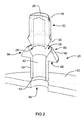
図1は、ホイールマウント(すなわちホイールハブ)12に、本発明の好ましい第1の実施形態による取付装置16を用いてホイールスタッド14を通して取り付けられるカーボンファイバ複合ホイール10を示す。
FIG. 1 shows a carbon
図示されている取付装置16は、ホイールスタッド14上に固定されることができる固定ナット18、固定ワッシャ20、及び、バッキングプレート22を有する。
The illustrated mounting
複合ホイール10は、一体型のカーボンファイバホイールである。ホイール10のハブ部23は、ホイール10がホイールマウント12に取り付けられるときにホイールマウント12のホイールスタッド14が挿入される5つの取付開口24を有する。ホイールスタッド14の各々が、細長い外ねじ(雄ねじ)付きピンであり、固定ナット18の各々のねじ孔25(図3)に対する相補的なねじを有する。
The
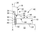
図2及び図3に最良に示されているように、固定ナット18の各々は円筒状のキャップであり、上部26と、ねじ孔25の周囲に環状に延びるベース28とを有する。ねじ孔25は中央固定軸X(図3)を有する。固定ナット18の各々が、ねじ孔25(図3)の縁から固定ナット18の半径方向外側部32まで延びる角度付きの係合部30を有する。係合部30は、固定軸Xに対する、固定ワッシャ20のヘッド38の係合面36との実質的に相補的な角度(余角)β(図4)を有する。その他の実施形態において、係合部30及び係合面36が平坦であってよく、若しくは、固定軸Xに対して90度の角度を成してもよく、又は、実質的に相補的な凹状又は凸状のカーブを有してもよいことが理解されよう。
As best shown in FIGS. 2 and 3, each of the fixing
図2及び図3に最良に示されているように、固定ワッシャ20は、環状体状のヘッド38と、軸方向に延びる円筒状スリーブ40とを有する。ヘッド38とスリーブ40とは単一の材料片(例えば金属)から一体的に形成されることができ、材料片は、ビレットから、鋳造、鍛造、又は機械加工される。固定開口42が、固定ワッシャ20の軸方向長さを通じて延びている。固定開口42も中央固定軸Xを有する。固定開口42の固定軸Xと固定ナット18のねじ孔25とは、図3に示されているようにワッシャ20とナットとが使用されているときに位置合わせされる。使用時に、固定開口42は、ホイールマウント12のホイールスタッド14(図1)を収容する。
As best shown in FIGS. 2 and 3, the
固定ワッシャ20のヘッド38は、略平坦なベース(底部)44を備え、ベース44は、複合ホイール10の、取付開口24の周囲の表面に面し且つ突き当てるように構成されている。さらに、固定ワッシャ20は固定側部46を有し、固定側部46は、取付開口24から外向きに、且つ、ベース44面から略軸方向に延びている。固定側部46はヘッド38の環状係合面36を有する。先に述べたように、係合面36は、固定軸Xに対する、固定ナット18のベース係合部30と相補的な角度(β)を有する。使用時、固定ナット18の係合部30は、固定ナット18がホイールスタッド14上に、複合ホイール10を固定ワッシャ20とホイールマウント12との間に固定するために組み付けられるときに固定ワッシャ20の係合面36と係合する。固定側部46は、環状のトレーリング面48も備え、面48は、係合面36のピーク位置から固定ワッシャ20のヘッド38の半径方向の遠位縁まで半径方向に延びている。従って、ヘッド38は、略三角環状体である。
The
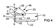
固定ワッシャ20のヘッド38は、複合ホイール10の取付開口24周囲の面とのクランプ接触領域を増大させ、それにより、クランプ力がこの領域に加えられる接触面積を増大させるように構成される。図4に示されているように、固定ワッシャ20の係合面36の角度βと、固定ナット18の係合部30の対応する角度とは、力Fが取付開口24の縁から離れる方向に分配され、そして、複合構造物上及び複合構造物内により均一に分配されることを保証する。角度βは、10から80°、より好ましくは、30から60°の範囲であり得る。例示されている実施形態において、角度βは45度である。
The
固定ワッシャ20のスリーブ40は、取付装置16に高い荷重が加えられたときに固定ワッシャ20が内側に崩壊することを防止するように設計されている。スリーブ40は、固定ワッシャ20のヘッド38のベース44から軸方向外側に、固定開口42の周囲に延びる。スリーブ40は、複合ホイール10の取付開口24内に延びるように構成されている。スリーブ40の本体50の半径方向の断面は円形である。さらに、スリーブ40の本体50の半径方向幅は、取付開口24の半径方向の幅よりも小さい。これが、スリーブ40の本体50の外側と複合ホイール10における取付開口24の内側との間の半径方向の隙間G(図4)を形成する。これが、スリーブ50がクランプ荷重の幾らかを取付開口24の壁部に伝達する可能性を低減する。
The
図2及び図5に最良に示されているように、各スリーブ40の遠位端52は、バッキングプレート22内に形成された相補的形状のスリーブ開口54に収容されるように構成されている。図5に最良に示されているように、スリーブ開口54とスリーブ40の遠位端52とは相補的な六角形の形状を有することができる。この相補的な形状は、スリーブ40のホイールマウント12に対する軸回転を実質的に防止する。スリーブ開口54は、スリーブ40の遠位端52の少なくとも一部がスリーブ開口54を通って移動することを可能にする寸法につくられている。スリーブ40の遠位端52は、また、スリーブ50の遠位端52と、バッキングプレート22の、スリーブ開口54近傍の面のセクションとの間にあそび(間隙)を設けるように、段状(ステップ状)の厚さに変化を有する。これは、スリーブ50と取付プレート22との間の軽い圧入をもたらし、取付装置16が押圧されるときにスリーブ40の遠位端52がスリーブ開口54を通ってスライドすることを可能にする。これは、スリーブ40がマウント12に接触し、そして、幾らかのクランプ荷重をマウント12に、又は、取付開口24若しくはスリーブ開口54内に半径方向に伝達する可能性を低減する。
As best shown in FIGS. 2 and 5, the
図2に最良に示されているように、バッキングプレート22は、ホイールマウント12と複合ホイール10との間に挿入されるように設計されている。図示されているバッキングプレート22は、環状に間隔をあけて配置された5つのスリーブ開口54を有する平坦な環状体プレートである。先に述べたように、スリーブ開口54は、固定ワッシャ20のスリーブ40セクションの相補的形状の遠位端52を収容して相互ロックするように設計された六角形の形状を有する。バッキングプレート22は、各固定ワッシャ20の、複合ホイール10のそれぞれの取付開口24内での軸回転を実質的に防止するように機能する。
As best shown in FIG. 2, the
固定ワッシャ20のヘッド38のベース44が、固定ワッシャ20のヘッド38を複合ホイール10上の適切な位置に固定するために、複合ホイール10の表面に接触して密着されることに留意されたい。これとは反対に、固定ワッシャ20のスリーブ40は複合ホイール10にいかなる場合も接触して密着されないことが好ましい。これが、スリーブ40が複合ホイール10内の取付開口24に対してスライドすることを可能にする。
Note that the
図6は、本発明の第2の実施形態による取付装置116を示す。図示されている取付装置116は、図1から図5に示した取付装置16と類似である。従って、図6に示した取付装置116における類似の機能には、図1から図5に示した取付装置16と同一の参照番号に100を加えた番号を付してある。
FIG. 6 shows a mounting
図6に示されている取付装置116は、ホイールスタッド(図示せず)上に固定されることができる固定ナット(図示せず)、固定ワッシャ120、及び、バッキングプレート122を有する。固定ワッシャ120の固定ナット118は、図2及び図3に示した各固定ナット18と同一の構造を有する。同様に、固定ワッシャ120及び円筒状スリーブ40も類似の構造を有する。この点に関し、固定ワッシャ120は、環状体状のヘッド138、及び、軸方向に延びる円筒状スリーブ140を有する。ヘッド138とスリーブ40とは一体的に形成されている。
The mounting
この実施形態においても、バッキングプレート122は、ホイールマウント(図示せず)と複合ホイール110との間に挿入されるように設計されている。この実施形態において、スリーブ開口154は、固定ワッシャ120のスリーブ140セクションの遠位端152を収容するが遠位端152と相互ロックはしないように設計された円形の形状を有する。この実施形態において、固定ワッシャ120の回転は、固定ワッシャ120のヘッド138のベース144から軸方向に突出しているフィンガ145により防止され、フィンガ145は、複合ホイール110の面内の相補的凹部147に収容され、固定されている。
Also in this embodiment, the
この実施形態において、スリーブ140の遠位端152はスリーブ開口154を通して挿入され、次いで、この遠位端は、スリーブ開口154よりも大きい寸法を有するように、巻かれた(rolled)エッジを形成するように変形される。巻かれたエッジは、バッキングプレート122のベース内に設けられた相補的環状溝155に固定される。この巻かれたエッジは、組立中に所定量の圧縮予荷重が取付装置116に加えられることを可能にする。また、この装置は、スリーブ140がスリーブ開口154を通ってバッキングプレート122に対して一方向にスライドすることを可能にするが、ファスナ(固定具)部材が取り外されるときに取付装置116の全体がばらばらになることを防止する。
In this embodiment, the
スリーブ140は、スリーブ140の主要本体よりも薄くされた遠位端152に向かう短いセクションを有する真直な部品として製造される。遠位端152は、部材を捲り上げるために成形金型内に押し込まれ、これは、プレススタッド(留め具)又はリベットを留め付けるのとほぼ同じ方法である。
The
この実施形態においては、どのような接着剤の使用も一般的に必要でなく、取付装置116の組立プロセスは単純で迅速である。
In this embodiment, the use of any adhesive is generally not required and the assembly process of the
例示された実施形態はカーボンファイバホイール10に関するが、例示された取付装置は、類似のタイプの任意の複合材料、構造物、又は部品(すなわち、マウントに固定されるように設計され、且つ、押圧連結による損傷が生じる複合材料、構造物、又は部品)と共に使用されるように適合させることが理解できる。
Although the illustrated embodiment relates to a
当業者は、本文中に記載した発明を、以上に詳細に記載したものと異なるように容易に変更及び修正することを理解することができる。本発明の精神及び範囲内にあるこれらの変更及び修正の全てを本発明が有することが理解することができる。 Those skilled in the art will understand that the invention described herein can be readily altered and modified to differ from those described in detail above. It can be understood that the invention has all of these changes and modifications within the spirit and scope of the invention.
用語「有する」(“comprise”,“comprises”)、「有した」(“comprised”)、又は、「有している」(“comprising”)は、本明細書(特許請求の範囲を有する)にて用いられる場合、これらの用語が、記載された機能、整数値、ステップ、又は部品の存在を詳細に示すが、1以上のその他の機能、整数値、ステップ、部品、又はこれらから成る群の存在を排除するものではないと解釈されるべきである。 The terms “comprise”, “comprises”, “comprised” or “comprising” are used herein (with claims). Where these terms detail the presence of the described function, integer value, step, or part, but are one or more other functions, integer values, steps, parts, or groups of these It should be construed not to exclude the existence of.
Claims (24)
前記複合ホイールは、前記細長い固定具部材が挿入される少なくとも1つの取付開口を備え、
固定軸を有し、前記細長い固定具部材が使用時に挿入される固定開口と、
前記複合ホイールの前記取付開口周囲の表面に面するように構成されたベースと、
前記固定ナットが前記細長い固定具部材に組み付けられるときに前記固定ナットの相補的部分と係合するように構成された少なくとも1つの係合面を有し、前記固定軸に対して略軸方向に前記取付開口から外側を向いた固定側部とを備える固定ワッシャを有し、
さらに、遠位端が、前記マウント又は該マウントの近傍に配置された部材に設けられたスリーブ開口に収容されるように構成され、前記固定開口の周囲の前記ベースから外側に向けて前記固定軸に対して略軸方向に延び、前記複合ホイールの前記取付開口内に延びるように構成されたスリーブを有する取付装置。 An attachment device used to attach at least one composite wheel to a mount using an elongate fixture member and a fastening nut that can be fastened to the elongate fixture member,
The compound wheel comprises at least one mounting opening into which the elongated fixture member is inserted;
A fixed opening having a fixed shaft, into which the elongated fixture member is inserted during use;
A base configured to face a surface around the mounting opening of the composite wheel;
Having at least one engagement surface configured to engage a complementary portion of the fixation nut when the fixation nut is assembled to the elongate fastener member, and substantially axially relative to the fixation axis A fixed washer provided with a fixed side facing outward from the mounting opening;
Further, the distal end is configured to be received in a sleeve opening provided in the mount or a member disposed in the vicinity of the mount, and the fixing shaft is directed outward from the base around the fixing opening. And a mounting device having a sleeve configured to extend substantially axially relative to the mounting opening of the composite wheel.
且つ、前記バッキング部材が、少なくとも2つの前記取付開口の各々を通して挿入される前記取付装置の前記スリーブと協働するように構成された少なくとも2つの前記スリーブ開口を有する請求項9から請求項15のいずれか一項に記載の取付装置。 The composite wheel has at least two of the mounting openings;
And, claim from claim 9 wherein the backing member has at least two of the sleeve opening is configured to cooperate with the sleeve of the attachment device inserted through each of two of said mounting aperture even without least The attachment device according to any one of 15.
前記固定ナットが相補的なねじ孔を有する請求項1から請求項21のいずれか一項に記載の取付装置。 The elongated fixture member has a male threaded surface;
The attachment device according to any one of claims 1 to 21, wherein the fixing nut has a complementary screw hole.
該固定ナットが、前記固定ワッシャの前記係合面に対して実質的に相補的な形状を有する係合部を備える請求項1から請求項23のいずれか一項に記載の取付装置。 A fixing nut that can be fixed to the elongated fixing member;
The attachment device according to any one of claims 1 to 23 , wherein the fixing nut includes an engaging portion having a shape substantially complementary to the engaging surface of the fixing washer.
Applications Claiming Priority (3)
| Application Number | Priority Date | Filing Date | Title |
|---|---|---|---|
| AU2011902599A AU2011902599A0 (en) | 2011-06-30 | Attachment System for Composite Components | |
| AU2011902599 | 2011-06-30 | ||
| PCT/AU2012/000598 WO2013000009A1 (en) | 2011-06-30 | 2012-05-30 | Attachment arrangement for composite wheels |
Publications (3)
| Publication Number | Publication Date |
|---|---|
| JP2014523829A JP2014523829A (en) | 2014-09-18 |
| JP2014523829A5 JP2014523829A5 (en) | 2015-04-02 |
| JP6068458B2 true JP6068458B2 (en) | 2017-01-25 |
Family
ID=47423278
Family Applications (1)
| Application Number | Title | Priority Date | Filing Date |
|---|---|---|---|
| JP2014517324A Active JP6068458B2 (en) | 2011-06-30 | 2012-05-30 | Compound wheel mounting device |
Country Status (8)
| Country | Link |
|---|---|
| US (1) | US9321301B2 (en) |
| EP (1) | EP2726301B1 (en) |
| JP (1) | JP6068458B2 (en) |
| KR (1) | KR101534091B1 (en) |
| CN (1) | CN103764406B (en) |
| AU (1) | AU2012261644C1 (en) |
| HK (1) | HK1192519A1 (en) |
| WO (1) | WO2013000009A1 (en) |
Families Citing this family (16)
| Publication number | Priority date | Publication date | Assignee | Title |
|---|---|---|---|---|
| DE102013205797B4 (en) | 2013-04-02 | 2023-08-03 | Bayerische Motoren Werke Aktiengesellschaft | Device for fastening a wheel disc made of fiber composite material |
| WO2015018593A1 (en) | 2013-08-05 | 2015-02-12 | Mubea Carbo Tech Gmbh | Wheel made out of a fiber reinforced plastic material |
| EP3038840B1 (en) | 2013-08-30 | 2022-03-16 | Mubea Carbo Tech GmbH | Composite wheel and insert |
| CN105517812B (en) | 2013-08-30 | 2017-09-12 | 碳革命有限公司 | Centre-lock mounting structure for combined wheels |
| US10486460B2 (en) | 2014-05-16 | 2019-11-26 | Basf Se | Thermoplastic wheel hub |
| WO2016168899A1 (en) | 2015-04-24 | 2016-10-27 | Carbon Revolution Pty Ltd | Method of producing thermally protected composite |
| US10065453B2 (en) * | 2016-02-17 | 2018-09-04 | Alex Global Technology, Inc. | Wheel securing structure of trucks |
| US9789729B2 (en) | 2016-03-17 | 2017-10-17 | Swift Engineering, Inc. | Wheels having multiple-piece composite structures |
| GB2548881B (en) * | 2016-03-31 | 2018-05-16 | Alex Global Tech Inc | Vehicle wheels having locking-hole reinforcement structure |
| AU2016202195B1 (en) * | 2016-04-08 | 2017-06-15 | Alex Global Technology, Inc. | Reinforcing structure of locking holes of trucks’ wheels |
| GB2541498B8 (en) | 2016-06-14 | 2017-11-29 | Dymag Group Ltd | Rim for a wheel |
| AU2018317492B2 (en) | 2017-08-18 | 2024-04-04 | Carbon Revolution Pty Ltd | Composite wheel with improved mounting formation |
| EP3870456A2 (en) | 2018-10-24 | 2021-09-01 | Mubea Carbo Tech GmbH | Wheel |
| WO2020187892A1 (en) | 2019-03-20 | 2020-09-24 | Mubea Carbo Tech Gmbh | Wheel for a vehicle |
| KR102468034B1 (en) * | 2020-07-01 | 2022-11-17 | 주식회사 포스코 | Vechile wheel |
| US20240253391A1 (en) * | 2021-05-17 | 2024-08-01 | Carbon Revolution Limited | Attachment arrangement for composite wheels |
Family Cites Families (17)
| Publication number | Priority date | Publication date | Assignee | Title |
|---|---|---|---|---|
| US2283860A (en) * | 1940-08-31 | 1942-05-19 | Sue Winston | Wheel structure |
| JPS5721762Y2 (en) * | 1975-11-11 | 1982-05-12 | ||
| JPS5591401A (en) * | 1978-12-28 | 1980-07-11 | Yokohama Rubber Co Ltd:The | Light alloy disc wheel |
| DE8231980U1 (en) * | 1982-11-13 | 1983-04-21 | Wipperfürth, Dieter, 6805 Heddesheim | WHEEL, IN PARTICULAR FOR MOTOR VEHICLES WITH A VARIABLE PUNCH CIRCLE |
| JPS6316201U (en) * | 1986-07-17 | 1988-02-03 | ||
| JPS63195001A (en) | 1987-02-09 | 1988-08-12 | Takaaki Aoki | Adjustment bush builtup body for wheel installing and wheel installation using the body |
| US5022712A (en) | 1988-12-30 | 1991-06-11 | Motor Wheel Corporation | Fiber-reinforced resin vehicle wheel mounting |
| US5711581A (en) * | 1994-01-27 | 1998-01-27 | Plumer; Mark J. | Wheel opening inserts and lug nut assemblies thereof for mounting vehicle wheels |
| US6068344A (en) * | 1996-08-29 | 2000-05-30 | Nether; Joseph G. | Wheel mount |
| JPH1111101A (en) * | 1997-06-23 | 1999-01-19 | Toyoda Gosei Co Ltd | Mounting structure of wheel cap |
| JP3788715B2 (en) * | 1999-03-04 | 2006-06-21 | 本田技研工業株式会社 | Wheel structure for vehicle |
| US6416135B1 (en) | 2000-06-30 | 2002-07-09 | Accuride Corporation | Means and method for attaching FRP wheels |
| JP2006153190A (en) * | 2004-11-30 | 2006-06-15 | Nissan Motor Co Ltd | Fastening member |
| DE102006010445B4 (en) * | 2006-03-03 | 2014-02-13 | Denk Engineering Gmbh | rim |
| CN201554739U (en) * | 2009-11-16 | 2010-08-18 | 陈国强 | Vehicle wheel hub fastener |
| US8911026B2 (en) * | 2011-06-29 | 2014-12-16 | Rick Pruden | Variable lug insert for wheel opening |
| USD710191S1 (en) * | 2012-12-20 | 2014-08-05 | Kabushiki Kaisha Yamazaki active | Washer |
-
2012
- 2012-05-30 KR KR1020147001716A patent/KR101534091B1/en active IP Right Grant
- 2012-05-30 WO PCT/AU2012/000598 patent/WO2013000009A1/en active Application Filing
- 2012-05-30 US US14/130,038 patent/US9321301B2/en active Active
- 2012-05-30 CN CN201280032621.7A patent/CN103764406B/en active Active
- 2012-05-30 EP EP12804406.2A patent/EP2726301B1/en active Active
- 2012-05-30 AU AU2012261644A patent/AU2012261644C1/en active Active
- 2012-05-30 JP JP2014517324A patent/JP6068458B2/en active Active
-
2014
- 2014-06-17 HK HK14105730.8A patent/HK1192519A1/en unknown
Also Published As
| Publication number | Publication date |
|---|---|
| AU2012261644B2 (en) | 2013-05-30 |
| AU2012261644A1 (en) | 2013-01-17 |
| WO2013000009A1 (en) | 2013-01-03 |
| EP2726301B1 (en) | 2017-04-05 |
| CN103764406A (en) | 2014-04-30 |
| EP2726301A1 (en) | 2014-05-07 |
| US20140175863A1 (en) | 2014-06-26 |
| EP2726301A4 (en) | 2015-03-11 |
| HK1192519A1 (en) | 2014-08-22 |
| KR20140030308A (en) | 2014-03-11 |
| US9321301B2 (en) | 2016-04-26 |
| JP2014523829A (en) | 2014-09-18 |
| AU2012261644C1 (en) | 2015-05-07 |
| KR101534091B1 (en) | 2015-07-07 |
| CN103764406B (en) | 2016-08-17 |
Similar Documents
| Publication | Publication Date | Title |
|---|---|---|
| JP6068458B2 (en) | Compound wheel mounting device | |
| JP6421186B2 (en) | Center lock mounting structure for composite wheels | |
| JP2014523829A5 (en) | ||
| US6190102B1 (en) | Studs for connecting a wheel and a brake element to a motor vehicle wheel hub unit | |
| US20240110590A1 (en) | ANTI-ROTATION and ANTI-LOOSENING WASHER, FASTENING CONNECTION MECHANISM and FASTENING METHOD Thereof | |
| KR20150108741A (en) | Profile clamp | |
| WO2012053250A1 (en) | Bolt and extraction tool | |
| KR20180038303A (en) | Fastening apparatus loosing prevention washer and having this same | |
| KR101850986B1 (en) | Self-locking nut | |
| US20060284472A1 (en) | Brakable wheel hub device | |
| KR101907342B1 (en) | Lock nut | |
| CN112534145A (en) | Lock washer and fastening structure | |
| KR20170002262A (en) | Fixture set with connecting surface for increasing fixation stability | |
| US20240253391A1 (en) | Attachment arrangement for composite wheels | |
| KR100398334B1 (en) | A fastening instrument | |
| JP5483611B2 (en) | Shaft coupling release structure | |
| KR200415212Y1 (en) | A nut for preventing loose | |
| AU2014311253B2 (en) | Centre-lock attachment arrangement for composite wheels | |
| KR101915633B1 (en) | Fastening tool for a self-locking nut | |
| KR101561839B1 (en) | anti-loose nut | |
| CN117320890A (en) | Mounting structure for composite wheel | |
| TWM513144U (en) | Wheel set for bicycle | |
| TW201632373A (en) | Bicycle wheel set | |
| KR20080093633A (en) | Joint apparatus |
Legal Events
| Date | Code | Title | Description |
|---|---|---|---|
| A521 | Request for written amendment filed |
Free format text: JAPANESE INTERMEDIATE CODE: A523 Effective date: 20150213 |
|
| A621 | Written request for application examination |
Free format text: JAPANESE INTERMEDIATE CODE: A621 Effective date: 20150224 |
|
| A977 | Report on retrieval |
Free format text: JAPANESE INTERMEDIATE CODE: A971007 Effective date: 20160202 |
|
| A131 | Notification of reasons for refusal |
Free format text: JAPANESE INTERMEDIATE CODE: A131 Effective date: 20160209 |
|
| A521 | Request for written amendment filed |
Free format text: JAPANESE INTERMEDIATE CODE: A523 Effective date: 20160404 |
|
| A131 | Notification of reasons for refusal |
Free format text: JAPANESE INTERMEDIATE CODE: A131 Effective date: 20160830 |
|
| A521 | Request for written amendment filed |
Free format text: JAPANESE INTERMEDIATE CODE: A523 Effective date: 20161117 |
|
| TRDD | Decision of grant or rejection written | ||
| A01 | Written decision to grant a patent or to grant a registration (utility model) |
Free format text: JAPANESE INTERMEDIATE CODE: A01 Effective date: 20161220 |
|
| A61 | First payment of annual fees (during grant procedure) |
Free format text: JAPANESE INTERMEDIATE CODE: A61 Effective date: 20161222 |
|
| R150 | Certificate of patent or registration of utility model |
Ref document number: 6068458 Country of ref document: JP Free format text: JAPANESE INTERMEDIATE CODE: R150 |
|
| S533 | Written request for registration of change of name |
Free format text: JAPANESE INTERMEDIATE CODE: R313533 |
|
| R350 | Written notification of registration of transfer |
Free format text: JAPANESE INTERMEDIATE CODE: R350 |
|
| R250 | Receipt of annual fees |
Free format text: JAPANESE INTERMEDIATE CODE: R250 |
|
| R250 | Receipt of annual fees |
Free format text: JAPANESE INTERMEDIATE CODE: R250 |
|
| R250 | Receipt of annual fees |
Free format text: JAPANESE INTERMEDIATE CODE: R250 |
|
| R250 | Receipt of annual fees |
Free format text: JAPANESE INTERMEDIATE CODE: R250 |
|
| R250 | Receipt of annual fees |
Free format text: JAPANESE INTERMEDIATE CODE: R250 |