JP6066730B2 - Method and apparatus for wireless transmission of data packet - Google Patents
Method and apparatus for wireless transmission of data packet Download PDFInfo
- Publication number
- JP6066730B2 JP6066730B2 JP2012555399A JP2012555399A JP6066730B2 JP 6066730 B2 JP6066730 B2 JP 6066730B2 JP 2012555399 A JP2012555399 A JP 2012555399A JP 2012555399 A JP2012555399 A JP 2012555399A JP 6066730 B2 JP6066730 B2 JP 6066730B2
- Authority
- JP
- Japan
- Prior art keywords
- preamble
- signal
- signal pulse
- sif
- duration
- Prior art date
- Legal status (The legal status is an assumption and is not a legal conclusion. Google has not performed a legal analysis and makes no representation as to the accuracy of the status listed.)
- Expired - Fee Related
Links
Images


Classifications
-
- H—ELECTRICITY
- H04—ELECTRIC COMMUNICATION TECHNIQUE
- H04W—WIRELESS COMMUNICATION NETWORKS
- H04W40/00—Communication routing or communication path finding
-
- H—ELECTRICITY
- H04—ELECTRIC COMMUNICATION TECHNIQUE
- H04B—TRANSMISSION
- H04B1/00—Details of transmission systems, not covered by a single one of groups H04B3/00 - H04B13/00; Details of transmission systems not characterised by the medium used for transmission
- H04B1/69—Spread spectrum techniques
- H04B1/7163—Spread spectrum techniques using impulse radio
- H04B1/7183—Synchronisation
-
- H—ELECTRICITY
- H04—ELECTRIC COMMUNICATION TECHNIQUE
- H04B—TRANSMISSION
- H04B1/00—Details of transmission systems, not covered by a single one of groups H04B3/00 - H04B13/00; Details of transmission systems not characterised by the medium used for transmission
- H04B1/69—Spread spectrum techniques
- H04B1/7163—Spread spectrum techniques using impulse radio
-
- H—ELECTRICITY
- H04—ELECTRIC COMMUNICATION TECHNIQUE
- H04B—TRANSMISSION
- H04B10/00—Transmission systems employing electromagnetic waves other than radio-waves, e.g. infrared, visible or ultraviolet light, or employing corpuscular radiation, e.g. quantum communication
- H04B10/50—Transmitters
- H04B10/516—Details of coding or modulation
- H04B10/524—Pulse modulation
-
- H—ELECTRICITY
- H04—ELECTRIC COMMUNICATION TECHNIQUE
- H04B—TRANSMISSION
- H04B14/00—Transmission systems not characterised by the medium used for transmission
- H04B14/02—Transmission systems not characterised by the medium used for transmission characterised by the use of pulse modulation
- H04B14/023—Transmission systems not characterised by the medium used for transmission characterised by the use of pulse modulation using pulse amplitude modulation
Description
本発明は、制御ネットワークのネットワークノード間でデータパケットを無線伝送する方法および装置に関するものである。 The present invention relates to a method and apparatus for wirelessly transmitting data packets between network nodes of a control network.
たとえば機械を制御するために制御ネットワークのネットワークノード間で無線通信する際には、無線インタフェースを介してデータパケットが伝送される。機械制御のための無線通信は、一方では非常に小さな待ち時間と、他方では非常に高いデータ伝送信頼性を必要とする。さらに制御ネットワークが上位の制御ネットワークとして使用される場合には、制御ネットワークが他の無線ネットワークと共存することが必要である。ここで高いデータ伝送信頼性を提供することは技術的な挑戦である。なぜならデータ伝送の際に信頼性を高めるための従来の措置の多くは待ち時間も長くするからである。さらに制御ネットワークにより制御される機械を備える工業的製造施設は、無線インタフェースを介する無線通信にとって難しい環境である。製造施設または機械を備える工業的製造個所には、データ伝送信号を阻止または反射する金属表面が存在し、そのため比較的大きな電磁ノイズが存在する。反射性の金属表面により、いわゆるマルチパス信号伝播が生じる。 For example, when wireless communication is performed between network nodes of a control network to control a machine, a data packet is transmitted through a wireless interface. Wireless communication for machine control requires very low latency on the one hand and very high data transmission reliability on the other hand. Furthermore, when the control network is used as an upper control network, the control network needs to coexist with other wireless networks. Providing high data transmission reliability here is a technical challenge. This is because many of the conventional measures for improving reliability during data transmission also increase the waiting time. Furthermore, an industrial manufacturing facility with machines controlled by a control network is a difficult environment for wireless communication over a wireless interface. In industrial manufacturing locations with manufacturing facilities or machines, there are metal surfaces that block or reflect data transmission signals, so there is relatively large electromagnetic noise. The reflective metal surface causes so-called multipath signal propagation.
従来の無線ネットワーク技術、たとえばBluetoothまたはIEEE802.15.4は、制御ネットワークに対する上記問題のため、とりわけ工業的製造環境または工業オートメーションにはほとんど適しない。 Conventional wireless network technologies, such as Bluetooth or IEEE 802.15.4, are not particularly suitable for industrial manufacturing environments or industrial automation due to the above problems for control networks.
したがって、データパケットが制御ネットワークのネットワークノード間で無線伝送される規格IEEE802.15.4aによるデータ伝送が提案された。しかし規格IEEE802.15.4aによるデータパケット伝送では大きなデータパケット損失率が発生することが判明した。データパケット損失率が高いと、データパケットのヘッダにあるプレアンブルが誤って識別されてしまう。このことはとりわけ、エネルギー検知により動作するネットワークノードの受信の際に生じる。 Therefore, data transmission according to the standard IEEE 802.15.4a in which data packets are wirelessly transmitted between network nodes of a control network has been proposed. However, it has been found that a large data packet loss rate occurs in data packet transmission according to the standard IEEE 802.15.4a. If the data packet loss rate is high, the preamble in the header of the data packet is erroneously identified. This occurs especially upon reception of a network node operating with energy sensing.
したがって本発明の課題は、工業的環境でも低いデータパケット損失率で、制御ネットワークのネットワークノード間でデータパケットを確実に伝送することのできる、制御ネットワークのネットワークノード間でのデータパケットの無線伝送方法および無線伝送装置を提供することである。 Therefore, an object of the present invention is to provide a method for wirelessly transmitting data packets between network nodes of a control network, which can reliably transmit data packets between network nodes of a control network with a low data packet loss rate even in an industrial environment. And providing a wireless transmission device.
この課題は本発明により、請求項1に記載された特徴を備える方法によって解決される。
This problem is solved according to the invention by a method comprising the features as claimed in
本発明は、制御ネットワークのネットワークノード間でデータパケットを無線伝送する方法を提供するものであり、データパケットは同期化のために、所定数のプレアンブルシンボルからなるそれぞれ1つのプレアンブルを有しており、第1の動作モードでは、プレアンブルのプレアンブルシンボルの各プレアンブルサブシンボルが伝送された個別信号パルスの位相によって符号化され、データパケットで伝送されたプレアンブルの信号識別能力を高めるための第2の動作モードでは、個別信号パルスの代わりに信号パルスシーケンスがプレアンブルサブシンボルの符号化のために伝送され、この信号パルスシーケンスでは個別信号パルスが複数回反復して伝送される。 The present invention provides a method for wirelessly transmitting a data packet between network nodes of a control network, and the data packet has one preamble each consisting of a predetermined number of preamble symbols for synchronization. In the first operation mode, each preamble sub-symbol of the preamble symbol of the preamble is encoded by the phase of the transmitted individual signal pulse, and the preamble for transmitting the signal transmitted in the data packet is enhanced. In the second operation mode, a signal pulse sequence is transmitted for encoding the preamble subsymbol instead of the individual signal pulse, and the individual signal pulse is transmitted a plurality of times repeatedly in this signal pulse sequence.
したがって本発明の方法では、プレアンブルの識別を容易にし、データパケット損失率を有意に低下する付加的な動作モードが導入される。 Thus, the method of the present invention introduces an additional mode of operation that facilitates preamble identification and significantly reduces the data packet loss rate.
本発明の方法の実施形態では第1の動作モードにおいて、プレアンブルサブシンボル間のシンボル間干渉(ISI)を回避するために設けられた信号休止が個別信号パルスに随伴する。 In an embodiment of the method of the invention, in the first mode of operation, a signal pause provided to avoid intersymbol interference (ISI) between preamble subsymbols accompanies the individual signal pulses.
本発明の方法の実施形態では第2の動作モードにおいても、プレアンブルサブシンボル間のシンボル間干渉(ISI)を回避するために設けられた信号休止が信号パルスシーケンスに随伴する。 In the method embodiment of the present invention, even in the second operation mode, a signal pause provided to avoid intersymbol interference (ISI) between preamble subsymbols accompanies the signal pulse sequence.
本発明の方法の実施形態では、プレアンブルの各プレアンブルシンボルが所定数のプレアンブルサブシンボルによって三値に符号化される。 In embodiments of the method of the present invention, the preamble symbol of the preamble is encoded into a three-value by the pre-amble sub-symbols of a predetermined number.
本発明の方法の実施形態では、第1の動作モードにおいて個別信号パルスが正、負または中性の符合を有する。 In an embodiment of the method of the invention, the individual signal pulses have a positive, negative or neutral sign in the first operating mode.
本発明の方法の実施形態では、第2の動作モードにおいて信号パルスシーケンスの信号パルスもそれぞれ正、負、または中性の符合を有する。 In an embodiment of the method of the invention, the signal pulses of the signal pulse sequence also have a positive, negative or neutral sign, respectively, in the second operating mode.
本発明の方法の別の実施形態では、第1の動作モードにおいて各プレアンブルサブシンボルが所定のパルス持続時間を備える個別信号パルスを有し、個別信号パルスには信号休止が付随し、この信号休止の持続時間は第1の拡散係数だけ前記個別信号パルスのパルス持続時間よりも長い。 In another embodiment of the method of the present invention, each preamble sub-symbol has an individual signal pulse with a predetermined pulse duration in the first mode of operation, and the individual signal pulse is accompanied by a signal pause. The duration of the pause is longer than the pulse duration of the individual signal pulse by a first spreading factor.
本発明の方法の別の実施形態では、第2の動作モードにおいて各プレアンブルサブシンボルが、位相が同じであり順次連続する所定数の個別信号パルスからなる信号パルスシーケンスを有し、信号パルスシーケンスの各個別信号パルスは所定のパルス持続時間を有する。 In another embodiment of the method of the present invention, each preamble sub-symbol in the second mode of operation has a signal pulse sequence comprising a predetermined number of individual signal pulses that have the same phase and are sequentially consecutive, and the signal pulse sequence Each individual signal pulse has a predetermined pulse duration.
本発明の方法の別の実施形態では、信号パルスシーケンスに、持続時間が第2の拡散係数だけ信号パルスシーケンスの持続時間よりも長い信号パルスが随伴する。 In another embodiment of the method of the present invention, the signal pulse sequence is accompanied by a signal pulse whose duration is longer than the duration of the signal pulse sequence by a second spreading factor.
本発明の方法の別の実施形態では、信号パルスシーケンスに、第1の動作モードでのプレアンブルサブシンボルの持続時間から信号パルスシーケンスの持続時間を減じた持続時間に対応する持続時間の信号パルスが随伴する。 In another embodiment of the method of the invention, the signal pulse sequence has a duration of the signal pulse corresponding to the duration of the preamble subsymbol in the first mode of operation minus the duration of the signal pulse sequence. Is accompanied.
本発明の方法の実施形態では、第1の動作モードにおいて、プレアンブルのプレアンブルシンボルの各プレアンブルサブシンボルが、伝送される個別信号パルスの位相によって規格IEEE802.15.4aに対応して符号化される。 In an embodiment of the method of the invention, in the first mode of operation, each preamble sub-symbol of the preamble symbol of the preamble is encoded according to the standard IEEE 802.15.4a according to the phase of the transmitted individual signal pulse. Is done.
本発明の方法の別の実施形態では、第1の動作モードで伝送される個別信号パルスと、第2の動作モードで伝送される信号パルスシーケンスの信号パルスとが、スペクトルパルス応答の極性から一義的に位相の定まるパルス形状を有する。 In another embodiment of the method of the invention, the individual signal pulses transmitted in the first mode of operation and the signal pulses of the signal pulse sequence transmitted in the second mode of operation are uniquely defined from the polarity of the spectral pulse response. It has a pulse shape with a fixed phase.
本発明の方法の別の実施形態では、このパルス形状はガウスパルス形状である。 In another embodiment of the method of the present invention, the pulse shape is a Gaussian pulse shape.
本発明の方法の別の実施形態では、このパルス形状はガウスダブレットパルス形状である。 In another embodiment of the method of the present invention, the pulse shape is a Gaussian doublet pulse shape.
本発明の方法の別の実施形態では、このパルス形状はルート・レイズド・コサインパルス形状である。 In another embodiment of the method of the present invention, the pulse shape is a root raised cosine pulse shape.
本発明の方法の別の実施形態では、データパケットのプレアンブルは、2n1のプレアンブルシンボルを備える同期化ヘッダと、2n2のプレアンブルシンボルを備えるスタートフレームデリミタ(SFD)とを有し、n1、n2は自然数である。 In another embodiment of the method of the invention, the preamble of the data packet comprises a synchronization header comprising 2 n1 preamble symbols and a start frame delimiter (SFD) comprising 2 n2 preamble symbols, n1 , N2 is a natural number.
本発明の方法の別の実施形態では、プレアンブルの受信された同期化ヘッダに基づきSYNC相関装置によって第1の相関値が計算され、この相関値に依存して制御ネットワーク内のネットワークノードの受信増幅器が調整される。 In another embodiment of the method of the present invention, a first correlation value is calculated by the SYNC correlator based on the received synchronization header of the preamble, and depending on this correlation value, the receiving amplifier of the network node in the control network Is adjusted.
本発明の方法の別の実施形態では、プレアンブルの受信されたスタートフレームデリミタ(SFD)に基づきSFD相関装置によって第2の相関値が、受信されたデータパケット内の有効データの開始を検知するために計算される。 In another embodiment of the method of the present invention, the second correlation value is detected by the SFD correlator based on the received start frame delimiter (SFD) of the preamble to detect the start of valid data in the received data packet. Is calculated.
本発明の方法の別の実施形態では、個別信号パルスのパルス持続時間は約2nsである。 In another embodiment of the method of the present invention, the pulse duration of the individual signal pulses is about 2 ns.
本発明の方法の別の実施形態では、第2の動作モードにおいて信号パルスシーケンスの順次連続する個別信号パルスの数NはN=4である。 In another embodiment of the method of the invention, the number N of consecutive individual signal pulses of the signal pulse sequence in the second operating mode is N = 4.
本発明はさらに、請求項14に記載の特徴を備えるネットワークノードを有する無線制御ネットワークに関するものである。
The invention further relates to a radio control network having a network node comprising the features of
本発明は、データパケットを伝送するネットワークノードを備える無線制御ネットワークを提供するものであり、データパケットは同期化のために、所定数のプレアンブルシンボルからなるそれぞれ1つのプレアンブルを有しており、第1の動作モードでは、プレアンブルのプレアンブルシンボルの各プレアンブルサブシンボルが伝送された個別信号パルスの位相によって符号化され、第2の動作モードではデータパケットで伝送されたプレアンブルの信号識別能力を高めるために、個別信号パルスの代わりに信号パルスシーケンスがプレアンブルサブシンボルの符号化のために伝送され、この信号パルスシーケンスでは個別信号パルスが複数回反復される。 The present invention provides a radio control network including a network node for transmitting a data packet, and the data packet has one preamble each consisting of a predetermined number of preamble symbols for synchronization, In the first operation mode, each preamble sub-symbol of the preamble symbol of the preamble is encoded by the phase of the transmitted individual signal pulse, and in the second operation mode, the signal identification capability of the preamble transmitted in the data packet is increased. To enhance, a signal pulse sequence is transmitted instead of individual signal pulses for the encoding of preamble subsymbols, in which the individual signal pulses are repeated a plurality of times.
本発明の無線制御ネットワークの実施形態では、無線制御ネットワークが第1の動作モードにおいてIEEE802.15.4aネットワークを形成する。 In an embodiment of the radio control network of the present invention, the radio control network forms an IEEE 802.15.4a network in the first operation mode.
本発明の方法および本発明の無線制御ネットワークのさらなる実施形態を、添付図面を参照して詳細に説明する。 Further embodiments of the inventive method and the inventive radio control network will be described in detail with reference to the accompanying drawings.
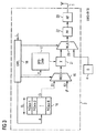
本発明の無線制御ネットワークでは、データパケットDPがネットワークノード1間で伝送される。図1から分かるように、図示の実施例で制御ネットワークのネットワークノード1は送信装置2および受信装置3からなり、これらはそれぞれデータ処理装置4、たとえばCPUまたはマイクロプロセッサに接続されている。さらに送信装置2と受信装置3は送受信アンテナ5に接続されている。送受信アンテナ5を介してネットワークノード1は、無線インタフェースにより無線制御ネットワークの他のネットワークノードと通信する。
In the radio control network of the present invention, the data packet DP is transmitted between the
実施形態では、送信装置2と受信装置3とがそれぞれ別個のアンテナを有する。すなわち送信装置2は送信アンテナに接続されており、受信装置3は受信アンテナに接続されている。ネットワークノード1は、とりわけアクチュエータ、センサおよび固有の電流供給源のような別の装置または回路部分を含むことができる。無線インタフェースを介してネットワークノード1は、データパケットDPを他のネットワークノードと通信のために交換する。これらのデータパケットDPは同期化のために、所定数のプレアンブルシンボルSからなるそれぞれ1つのプレアンブルPREを有している。
In the embodiment, the
第1の動作モードでは、プレアンブルPREのシンボルSのプレアンブル1の各プレアンブルサブシンボルCが伝送された個別信号パルスの位相によって符号化される。第2の動作モードではデータパケットDPで伝送されたプレアンブルPREの信号識別能力を高めるために、個別信号パルスの代わりに信号パルスシーケンスSIFがそれぞれのプレアンブルサブシンボルCの符号化のために伝送され、この個別信号パルスの信号パルスシーケンスSIFを形成するために第1の動作モードで使用される個別信号パルスが複数回反復して伝送される。
In the first operation mode, each preamble subsymbol C of the
第2の動作モードでは、データパケットDPで伝送されたプレアンブルPREの信号識別能力が第1の動作モードに対して高められる。これによりネットワークノード1の受信装置3は受信されたデータパケットのプレアンブルPREを簡単に識別することができる。これによりデータパケット損失率DPVRが有意に低下する。実施形態では、図1に示したようにネットワークノード1が2つの動作モード間で切換可能である。その代わりにネットワークノード1は特定の動作モード、とりわけ第2の動作モードに対して前もって構成しておくことができる。
In the second operation mode, the signal identification capability of the preamble PRE transmitted in the data packet DP is enhanced with respect to the first operation mode. As a result, the receiving
第1の動作モードでも第2の動作モードでも、個別信号パルスまたは信号パルスシーケンスSIFにはそれぞれ信号休止SPが後に続く。この信号休止は、プレアンブルサブシンボルC間のシンボル間干渉を回避するために設けられている。ここで各プレアンブルシンボルSは、好ましくは所定数のプレアンブルサブシンボルCによって三値に符号化されている。三値に符号化される場合には、個別信号パルスまたは信号パルスシーケンスSIFの信号パルスはそれぞれ正、負または中性の符合を有する。プレアンブルサブシンボルCは、第1の動作モードでは所定のパルス持続時間の個別信号パルスを有する。このパルス持続時間はたとえば2nsである。ここで第1の動作モードでは、個別信号パルスは信号休止SPの後に続き、この信号休止の持続時間は実施形態では、第1の拡散係数L1だけ個別信号パルスのパルス持続時間より長い。 In each of the first and second operation modes, the individual signal pulse or signal pulse sequence SIF is followed by a signal pause SP. This signal pause is provided in order to avoid intersymbol interference between preamble subsymbols C. Here, each preamble symbol S is preferably ternary encoded by a predetermined number of preamble subsymbols C. When encoded into ternary values , the individual signal pulses or the signal pulses of the signal pulse sequence SIF each have a positive, negative or neutral sign. The preamble subsymbol C has individual signal pulses of a predetermined pulse duration in the first operating mode. This pulse duration is, for example, 2 ns. Here, in the first mode of operation, the individual signal pulse follows the signal pause SP, and in this embodiment the duration of this signal pause is longer than the pulse duration of the individual signal pulse by a first spreading factor L1.
第1の動作モードでは、プレアンブルPREのプレアンブルシンボルSの各プレアンブルサブシンボルCが伝送された個別信号パルスの位相によって符合化されているが、第2の動作モードではデータパケットDPで伝送されたプレアンブルPREの信号識別能力を高めるために、個別信号パルスの代わりに信号パルスシーケンスSIFがそれぞれのプレアンブルサブシンボルCを符号化するために伝送される。ここで各プレアンブルサブシンボルCは、第2の動作モードでは、位相が同じであり順次連続する所定数の個別信号パルスからなる信号パルスシーケンスSIFを有する。信号パルスシーケンスSIFの各信号パルスは、所定のパルス持続時間を有する。信号パルスシーケンスには信号休止SPが後に続く。この信号休止SPは実施形態では、第2の拡散係数L2だけ信号パルスシーケンスSIFの持続時間よりも長い。 In the first operation mode, each preamble sub-symbol C of the preamble symbol S of the preamble PRE is encoded by the phase of the transmitted individual signal pulse, but in the second operation mode, it is transmitted in the data packet DP. In order to increase the signal identification capability of the preamble PRE, a signal pulse sequence SIF is transmitted to encode each preamble subsymbol C instead of individual signal pulses. Here, each preamble sub-symbol C has a signal pulse sequence SIF composed of a predetermined number of individual signal pulses that have the same phase and are sequentially consecutive in the second operation mode. Each signal pulse of the signal pulse sequence SIF has a predetermined pulse duration. The signal pulse sequence is followed by a signal pause SP. In the embodiment, this signal pause SP is longer than the duration of the signal pulse sequence SIF by the second spreading factor L2.
択一的な実施形態では、信号休止SPが、第1の動作モードでのプレアンブルサブシンボルCの持続時間から信号パルスシーケンスSIFの持続時間を減じた持続時間に相当する持続時間を有する。この実施形態は、プレアンブルサブシンボル長が全体として両動作モードで同じままであるという利点を有する。これにより第1の実施形態と比較して待ち時間が短くなる。したがって、信号休止に時間が第2の拡散係数L2だけ信号パルスシーケンスの時間よりも長い第1の変形実施例または実施形態は、信号のマルチパス信号伝播に対して高い耐性を有する。 In an alternative embodiment, the signal pause SP has a duration that corresponds to the duration of the preamble sub-symbol C in the first mode of operation minus the duration of the signal pulse sequence SIF. This embodiment has the advantage that the preamble subsymbol length remains the same in both operating modes as a whole. As a result, the waiting time is shorter than in the first embodiment. Thus, the first variant embodiment or embodiment in which the signal pause time is longer than the signal pulse sequence time by the second spreading factor L2 is highly resistant to multipath signal propagation of the signal.
本発明の可能な実施形態では、図1に示したネットワークノードの第1の動作モードにおいて、プレアンブルPREのプレアンブルシンボルSの各プレアンブルサブシンボルCが、伝送される個別信号パルスの位相によって規格IEEE802.15.4aに準拠して符号化される。したがって図1に示したネットワークノード1は標準規格であり、第2の動作モードによって拡張される。第2の動作モードで伝送される信号パルスシーケンスSIFは、パルス形状が実施形態では第1の動作モードで伝送されるパルスまたは個別信号パルスのパルス形状に相当する信号パルスからなる。ここで信号パルスシーケンスSIFの信号パルスのパルス形状の位相は、スペクトルパルス応答から一義的に得られる。
In a possible embodiment of the invention, in the first operating mode of the network node shown in FIG. 1, each preamble subsymbol C of the preamble symbol S of the preamble PRE is standardized according to the phase of the transmitted individual signal pulse. It is encoded in conformity with IEEE802.15.4a. Therefore, the
別の実施形態では、このパルス形状はガウスパルス形状である。その代わりにパルス形状は、ガウスダブレットパルス形状またはルートライズドコサイン(RRC)形状とすることもできる。図1に示したようにネットワークノード1から発するデータパケットDPは同期化のためにそれぞれ1つのプレアンブルPREを有する。ここでデータパケットDPのプレアンブルは好ましくは2n1のプレアンブルシンボルを備える1つの同期化ヘッダSYNCと、2n2のプレアンブルシンボルを備える1つのスタートフレームデリミタを含み、n1,n2は自然数である。
In another embodiment, the pulse shape is a Gaussian pulse shape. Alternatively, the pulse shape can be a Gaussian doublet pulse shape or a rooted cosine (RRC) shape. As shown in FIG. 1, each data packet DP originating from the
本発明のネットワークノード1の可能な実施形態では、受信装置3が相関装置を含む。
In a possible embodiment of the
可能な実施形態では、データパケットDPのプレアンブルPRE受信された同期化ヘッダSYNCに基づいて、SYNC相関装置によってネットワークノード1の受信装置3内で第1の相関値が計算され、その相関値に依存してネットワークノード1の受信増幅器が調整される。
In a possible embodiment, based on the synchronization header SYNC received in the preamble PRE of the data packet DP, a first correlation value is calculated in the receiving
可能な実施形態では、ネットワークノード1の受信装置3がいわゆるSFD相関装置を有する。プレアンブルPREのスタートフレームデリミタSFDに基づき、受信装置3のこのSFD相関装置によって、受信されたデータパケットDP内の有効データの開始を検出するために第2の相関値が計算される。
In a possible embodiment, the receiving
図1に示したネットワークノード1内の受信装置3は、超広帯域(UWB)インパルス応答(IR)受信器とすることができ、この受信器は可能な実施形態では図2に示すように構成されている。受信装置3または受信器3は図2に示すように、アンテナ5を介して受信された信号をダウンコンバートするためのHF段6を有する。HF段6は1つまたは複数の信号増幅器ならびにバンドパスフィルタBPFを含むことができ、ベースバンド信号を形成する。このベースバンド信号は信号二乗段7に印加される。ダウンコンバートされ、バンドパスフィルタリングされた信号は二乗され、信号積分器8に印加される。信号積分器8は信号をシンボル時間Tsで積分し、積分された値をアナログ/デジタル変換器9に印加する。形成されたデジタル値はデータ処理装置、たとえば図1に示したデータ処理装置4に供給される。さらに受信装置3は図2に示すように累積装置10を含む。この累積装置10はプレアンブルサブシンボルCに関するデジタル値を累積する。この累積装置10は可能な実施形態では、オーバサンプリング係数OFによって調整される。オーバサンプリング係数OFはプレアンブルサブシンボルの持続時間Tcとシンボルの持続時間Tsとの比から得られる。
The
累積装置10は出力側で受信装置3の第1の相関装置11と接続されている。受信装置3により受信されたデータパケットDPはプレアンブルPREを含んでおり、このプレアンブルPREは同期化ヘッダSYNCとスタートフレームデリミタSFDからなる。図2に示したプレアングル同期化ヘッダ相関装置11は、プレアンブルPREの受信された同期化ヘッダSYNCに基づき、第1の相関値KW1を計算する。この第1の相関値KW1は自動利得制御器12に出力される。自動利得制御器12または増幅制御部12は、第1の相関値KW1に依存して、HF段6に含まれている少なくとも1つの受信増幅器の増幅率を、受信された信号に受信装置を整合するために調整する。相関装置11は図2に示した実施形態ではレジスタ13に接続されている。このレジスタにはプレアンブルサブシンボルCまたはプレアンブルチップC、たとえば31のプレアンブルサブシンボルが存在する。レジスタに記憶されたプレアンブルサブシンボルCは、記憶された識別テンプレートを形成する。相関装置11から出力された相関値は、受信されたプレアンブルPREがどれだけ予想されるプレアンブルに似ているかを指示する。相関値は、可能な実施形態では閾値比較器によって閾値THと比較される。計算された相関値が閾値を上回ると直ちに、受信されたプレアンブルPREが予想されるプレアンブルに対応することが識別される。したがって閾値THを上回るとプレアンブルシンボルが識別される。
The
図2に示した実施形態では、受信されたデータパケットDPのスタートフレームデリミタSFDに基づきSFD相関装置14よって第2の相関値KW2が、データパケットDP内の有効データの開始を選択するために計算される。SFD相関器14はレジスタ15に接続されており、このレジスタにはたとえば予想されるスタートフレームデリミタSFDの所定のプレアンブルシンボルSが存在する。スタートフレームデリミタSFDが識別されると、データ処理装置4が図2に示すように、ADC9から出力された有効データのデータ処理をするために作動される。
In the embodiment shown in FIG. 2, the second correlation value KW2 is calculated by the
図3は、図1に示されたネットワークノード1に使用される送信装置2の実施例を示す概略的ブロック回路図である。図3に示した実施例で送信装置2は超広帯域(UWB)インパルス応答(IR)送信器である。図3に示した回路部分は、本発明の方法で使用されるデータパケットDPのプレアンブルPREを生成する。たとえばRAMメモリであるデータメモリ16内には、たとえば8つのプレアンブルコードPコード1からPコード8がある。これらはそれぞれ所定数のプレアンブルサブシンボルCを含んでおり、たとえば31のプレアンブルサブシンボルCを含んでいる。プレアンブルコード内のプレアンブルサブシンボルCの数は、図3に示すようにコード長CLを形成する。第2のデータメモリ17には標準SFD(スタートフレームデリミタ)コードのプレアンブルシンボルが存在する。たとえばRAMである2つのデータメモリ16,17は制御論理回路18によってアドレシングされる。さらに制御論理回路18は、図3に示すように制御線路を介して2つのマルチプレクサ19,20を制御する。制御論理回路18は複数のカウンタを含むことができる。
FIG. 3 is a schematic block circuit diagram showing an embodiment of the
制御論理回路18のカウンタは、可能な実施形態では値ゼロから拡散係数L1まで計数する。計数値がゼロのときマルチプレクサ19の第1の入力端E1が導通され、このカウンタがその他の計数値のときマルチプレクサ19の第2の入力端が導通される。そしてメモリ16でちょうどアドレシングされたプレアンブルコードのプレアンブルサブシンボルCiにゼロまたはゼロ値の数が付加される。付加されたゼロ値の数は信号休止SPを形成し、拡散係数L−1に相当する。拡散係数Lは、制御論理回路18の可能な実施形態では調整可能である。拡散係数Lがたとえば16であれば、メモリ16から読み出される各プレアンブルサブシンボルCには15が付加され、それから次のプレアンブルサブシンボルCが導通される。マルチプレクサ19内に形成されたプレアンブルサブシンボルCのシーケンスはそれぞれ拡散係数Lに対応する数のゼロ値を有するようになり、図3に示すように乗算器21に供給される。乗算器はメモリ17から読み出された標準SFDコードのプレアンブルシンボルをマルチプレクサ19から出力されたシーケンスと乗算する。プレアンブルPREが完成されると直ちに、制御論理回路18はマルチプレクサ20をデータ入力端に切り換える。このデータ入力端はたとえば図1に示したデータ処理装置4と接続されている。マルチプレクサ20の出力端はパルス形成器22と接続されており、このパルス形成器の出力端はHF段23に接続されている。
The counter of the
可能な実施形態で制御論理回路18は、カウンタをクロッキングするための集積クロック発生器を有する。可能な実施形態でクロック発生器は500MHzの周波数のクロック信号を発生する。このクロック信号はマルチプレクサ19を制御するためにカウンタに印加される。その代わりにクロック信号CLKを外部から制御論理回路18に供給することもできる。
In a possible embodiment, the
図4aは、本発明の方法および装置に使用されるデータパケットDPのプレアンブルPREのデータ構造を示す。プレアンブルPREはスタートフレームデリミタSFDを備える同期化ヘッダSYNCからなる。同期化ヘッダSYNCは好ましくは2n1のプレアンブルシンボルSからなる。図4aに示した実施例では、同期化ヘッダSYNCはたとえば64のプレアンブルシンボルSを有する(n1=6)。さらにプレアンブルPREは、2n2のプレアンブルシンボルを備えるスタートフレームデリミタSFD、たとえば図4aに示すように8つのプレアンブルシンボルを備えるスタートフレームデリミタSFDを含む(n2=3)。各プレアンブルシンボルSはプレアンブルサブシンボルCまたはコードチップCiからなる。本発明の方法の第1の動作モードでは、プレアンブルPREのプレアンブルシンボルSの各プレアンブルサブシンボルCが伝送された個別信号パルスの位相によって符号化される。このことは各コードチップCiが、信号休止SPを形成するゼロ値のシーケンスが後に続く個別信号パルスを有していることを意味する。信号休止SPは、プレアンブルサブシンボルまたはコードチップCi間のシンボル間干渉ISIを回避するために用いられる。信号パルスは好ましくは正、負、または中性の符合を有する。ここで各プレアンブルシンボルSは、好ましくは所定数のプレアンブルサブシンボルCによって三値に符号化される。好ましくは各プレアンブルサブシンボルは、図4aに示すように31のプレアンブルシンボルによって三値に符号化される。各プレアンブルサブシンボルまたはコードチップCiの開始時に第1の動作モードでは、たとえば2nsの所定のパルス持続時間の個別信号パルスが設けられる。個別信号パルスには複数のゼロ値が続く。ゼロ値の数は拡散係数Lマイナス1により与えられる。拡散係数L=16であれば、個別信号パルスに15のゼロ値が、拡散係数Lが64であれば個別信号パルスに63のゼロ値が続く。ゼロ値の数が多ければ多いほど、すなわち後続の信号休止SPが長ければ長いほど、プレアンブルPREはマルチパス信号伝播による障害に対して強い耐性を有する。しかしプレアンブルサブシンボルの長さが長いと待ち時間が大きくなる。本発明の方法の第1の動作モードでは、各プレアンブルサブシンボルまたはコードチップCiが伝送される個別信号パルスの位相によって符号化され、個別信号パルスは所定のパルス形状および所定のパルス持続時間を有する。個別信号パルスは、ガウスパルス形状、ガウスダブレットパルス形状またはルートライズドコサイン(RRC)パルス形状とすることができる。個別信号パルスのパルス持続時間は2ns以下であるから、個別信号パルスは伝送時にわずかなエネルギー量しか有しておらず、とりわけノイズのある環境では受信装置の側で識別するのが困難である。
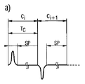
FIG. 4a shows the data structure of the preamble PRE of the data packet DP used in the method and apparatus of the present invention. The preamble PRE includes a synchronization header SYNC including a start frame delimiter SFD. The synchronization header SYNC preferably consists of 2 n1 preamble symbols S. In the embodiment shown in FIG. 4a, the synchronization header SYNC has, for example, 64 preamble symbols S (n1 = 6). Further preamble PRE is the start frame delimiter SFD comprising a preamble symbol of 2 n2, including a start frame delimiter SFD which comprises eight preamble symbols as shown in FIG. 4a for example (n2 = 3). Each preamble symbol S includes a preamble sub-symbol C or a code chip Ci. In the first mode of operation of the method of the invention, each preamble subsymbol C of the preamble symbol S of the preamble PRE is encoded by the phase of the transmitted individual signal pulse. This means that each code chip Ci has an individual signal pulse followed by a sequence of zero values forming a signal pause SP. The signal pause SP is used to avoid intersymbol interference ISI between preamble sub-symbols or code chips Ci. The signal pulse preferably has a positive, negative or neutral sign. Here, each preamble symbol S is preferably ternary encoded by a predetermined number of preamble subsymbols C. Preferably each pre-amble sub-symbols are encoded into a three-value by the pre-amble symbol 31 as shown in Figure 4a. In the first operating mode at the start of each preamble sub-symbol or code chip Ci, individual signal pulses with a predetermined pulse duration of 2 ns, for example, are provided. Individual signal pulses are followed by a plurality of zero values. The number of zero values is given by the diffusion
図5aは、本発明の方法の第1の動作モードにおける信号伝送を説明する信号線図である。この動作モードではまず個別信号パルスが伝送され、所定数のゼロ値が続く。ゼロ値の数は拡散係数Lにより決定される。たとえば拡散係数L=16のとき15のゼロ値が伝送される。パルス持続時間が2nsであれば、プレアンブルサブシンボルCの持続時間Tcは16×2ns=32nsである。拡散係数が64のとき、プレアンブルサブシンボルの持続時間Tcは128nsである。たとえばプレアンブルシンボルS内のプレアンブルサブシンボルCの数またはコード長CLがCL=31であれば、プレアンブルPRE内のシンボルの持続時間は約4μsである。図5aに示した例では、まず正の符号の個別信号パルスが伝送され、それに負の符号の個別信号パルスが続く。 FIG. 5a is a signal diagram illustrating signal transmission in the first mode of operation of the method of the present invention. In this mode of operation, individual signal pulses are first transmitted, followed by a predetermined number of zero values. The number of zero values is determined by the diffusion coefficient L. For example, when the diffusion coefficient L = 16, 15 zero values are transmitted. If the pulse duration is 2 ns, the duration Tc of the preamble subsymbol C is 16 × 2 ns = 32 ns. When the spreading factor is 64, the duration Tc of the preamble subsymbol is 128 ns. For example, if the number of preamble subsymbols C in the preamble symbol S or the code length CL is CL = 31, the duration of the symbols in the preamble PRE is about 4 μs. In the example shown in FIG. 5a, an individual signal pulse with a positive sign is transmitted first, followed by an individual signal pulse with a negative sign.
本発明の方法の可能な実施形態では各プレアンブルサブシンボルCが三値に符号化されており、各個別信号パルスはそれぞれ正、負または中性の符合VZを有する。他の符号化、たとえば2進符号化も可能である。
In a possible embodiment of the method of the invention, each preamble subsymbol C is coded in ternary , and each individual signal pulse has a positive, negative or neutral sign VZ. Other encodings are possible, for example binary encoding.
図5bは、本発明の方法の第2の動作モードを説明するための信号線図である。第2の動作モードでは、データパケットDPで伝送されるプレアンブルPREの信号識別能力を高めるために、個別信号パルスではなく信号パルスシーケンスSIFがプレアンブルシンボルSの符号化のために伝送される。ここで第1の動作モードで伝送される個別信号パルスは何回も繰り返して伝送される。第2の動作モードでは各プレアンブルサブシンボルCが、順次連続し位相が同じである所定数Nの個別信号パルスを有する。図5bに示された例で信号パルスシーケンスSIFは順次連続する4つの個別信号パルス(N=4)を有する。4つのパルスからなる信号パルスシーケンスSIFには信号休止SPが後に続く。可能な変形実施形態では、信号休止SPは第2の拡散係数L2だけ信号パルスシーケンスの時間よりも長い。拡散係数L2は、第1の動作モードで使用された拡散係数L1と同じでよい。第2の拡散係数L2が、たとえば図5bの実施例のように16であれば、信号パルスシーケンスSIFには4×15=60のゼロ値を含む信号休止SPが続く。そして次のコードチップCit1またはプレアンブルサブシンボルの次の信号パルスシーケンスSIFが続く。これは図5bに示す例では負の符号を有する順次連続する4つの信号パルスからなる信号パルスシーケンスSIFである。 FIG. 5b is a signal diagram for explaining the second operation mode of the method of the present invention. In the second operation mode, a signal pulse sequence SIF, not individual signal pulses, is transmitted for encoding the preamble symbol S in order to enhance the signal identification capability of the preamble PRE transmitted in the data packet DP. Here, the individual signal pulse transmitted in the first operation mode is transmitted repeatedly many times. In the second operation mode, each preamble sub-symbol C has a predetermined number N of individual signal pulses that are sequentially consecutive and have the same phase. In the example shown in FIG. 5b, the signal pulse sequence SIF comprises four consecutive individual signal pulses (N = 4). The signal pulse sequence SIF consisting of four pulses is followed by a signal pause SP. In a possible variant embodiment, the signal pause SP is longer than the time of the signal pulse sequence by a second spreading factor L2. The diffusion coefficient L2 may be the same as the diffusion coefficient L1 used in the first operation mode. If the second spreading factor L2 is 16, for example as in the embodiment of FIG. 5b, the signal pulse sequence SIF is followed by a signal pause SP containing 4 × 15 = 60 zero values. The next signal pulse sequence SIF of the next code chip Cit1 or preamble subsymbol follows. This is a signal pulse sequence SIF consisting of four consecutive signal pulses having a negative sign in the example shown in FIG. 5b.
択一的な実施形態では、信号休止SPの時間は、第1の動作モードでのプレアンブルサブシンボルCまたはチップコードの持続時間から信号パルスシーケンスSIFの持続時間を減じた持続時間に相当する。この実施形態は、コードチップCiまたはプレアンブルサブシンボルの持続時間が両方の動作モードで同じ長さであるという利点を提供する。その点で、他の択一的実施形態と比較してプレアンブルサブシンボルの長さが短いので待ち時間が改善される。マルチパス信号伝播による障害に対する耐性は、とくに図5bに示した実施形態では信号休止SPの長さが長く、これと結び付いてプレアンブルサブシンボルC間のシンボル間干渉ISIが小さいので比較的に高くなっている。 In an alternative embodiment, the duration of the signal pause SP corresponds to the duration of the preamble sub-symbol C or chip code in the first mode of operation minus the duration of the signal pulse sequence SIF. This embodiment offers the advantage that the duration of the code chip Ci or preamble subsymbol is the same length in both operating modes. In that respect, the latency is improved because the length of the preamble sub-symbol is shorter compared to other alternative embodiments. In particular, in the embodiment shown in FIG. 5b, the tolerance to the failure due to multipath signal propagation is relatively high because the length of the signal pause SP is long, and the intersymbol interference ISI between the preamble sub-symbols C is small in connection with this. It has become.
したがって図5bに示した第2の動作モードでは、プレアンブルPRE内で個別信号パルスではなく信号パルスシーケンスSIFが伝送される。この信号パルスシーケンスSIFには比較的長い信号休止SPが続く。この信号休止SPは図5bに示した実施形態では信号パルスシーケンスSIFのパルスの数に相応して延長される。図5bに示した変形実施形態では、平均照射エネルギーは変化せず、エネルギー収支は一定のままである。 Therefore, in the second operating mode shown in FIG. 5b, the signal pulse sequence SIF is transmitted in the preamble PRE instead of the individual signal pulses. This signal pulse sequence SIF is followed by a relatively long signal pause SP. This signal pause SP is extended in accordance with the number of pulses of the signal pulse sequence SIF in the embodiment shown in FIG. 5b. In the variant embodiment shown in FIG. 5b, the average irradiation energy does not change and the energy balance remains constant.
本発明の方法では第2の動作モードで、プレアンブルPREのプレアンブルシンボルSが図5bに示す変形実施形態では延長される。これにより識別能力が、データパケットDPの反復を回避できるほどに改善または向上される。好ましくはプレアンブルシンボルSの変形は時間およびエネルギーに関しては中性であるが、好ましいことにはデータパケット損失率DPVRは格段に低下される。 In the method of the invention, in the second operating mode, the preamble symbol S of the preamble PRE is extended in the variant embodiment shown in FIG. 5b. As a result, the identification capability is improved or improved so as to avoid repetition of the data packet DP. Preferably, the deformation of the preamble symbol S is neutral with respect to time and energy, but preferably the data packet loss rate DPVR is significantly reduced.
本発明の方法で好ましくはパルス波形は、スペクトルパルス応答の極性から位相が一義的に定められるように選択される。たとえばパルス波形として、ガウスパルス波形、ガウスダブレットパルス波形、またはルートライズドコサインパルス波形が選択される。 In the method of the present invention, the pulse waveform is preferably selected so that the phase is uniquely determined from the polarity of the spectral pulse response. For example, a Gaussian pulse waveform, a Gaussian doublet pulse waveform, or a rooted cosine pulse waveform is selected as the pulse waveform.
可能な実施形態では、受信装置3で受信されたシンボルの符合VZが二乗の前に求められ、この求められた符合VZがプレアンブル識別のために使用される。この変形実施形態では、プレアンブルシンボルSの識別のための識別能力がさらに改善または向上される。本実施形態ではそのために、図2に示した受信装置3でHF段6の後方に符合識別回路が設けられている。この符合識別回路は信号パルスの符合VZを求め、求められた符合をAD変換段9の後方にビットまたは符合ビットとして再び挿入する。
In a possible embodiment, the sign VZ of the symbol received at the receiving
図4bは、本発明の方法で使用されるデータパケットDPの詳細を示す。データ部分はバースト位置変調(BPM)により変調することができる。ここでは非常に短くエネルギーの高いパルスシーケンスを送信することができ、これに長い休止が続く。伝送された情報は、シンボルに対する時間内のパルスバースト位置により変調される。すなわち前半分か後半分かで変調される。ここでは常に半分の前4分の1だけが使用される。すなわち各シンボル時間の最初の4分の1と第3の4分の1が使用される。各半分の第2の4分の1は、シンボル間干渉を低減するために安全間隔またはガードインターバルGIとして設けられる。したがってシンボルインターバルは図4bに示すデータ構造を有する。シンボルインターバルは長さTBPPMを有する2つの半分からなり、両半分にはそれぞれ第2の半分がガードインターバルGIとして空けられている。残った2つの4分の1は長さtburstの複数のオン・ホッピング位置に分割される。各データビットごとに、組織畳み込み復号器のチェックサムを含む第2のビットがパルスバーストの個々のパルスの位相に符号化される。 FIG. 4b shows the details of the data packet DP used in the method of the present invention. The data portion can be modulated by burst position modulation (BPM). Here, a very short high energy pulse sequence can be transmitted, followed by a long pause. The transmitted information is modulated by the pulse burst position in time for the symbol. That is, it is modulated in the front half or the rear half. Here only half of the previous quarter is always used. That is, the first quarter and the third quarter of each symbol time are used. The second quarter of each half is provided as a safety or guard interval GI to reduce intersymbol interference. The symbol interval thus has the data structure shown in FIG. 4b. The symbol interval is composed of two halves having a length T BPPM, and a second half of each half is provided as a guard interval GI. The remaining two quarters are divided into a plurality of on-hopping positions of length tburst . For each data bit, a second bit containing the checksum of the systematic convolutional decoder is encoded into the phase of the individual pulses of the pulse burst.
図6は、制御ネットワークのネットワークノード1間でデータパケットDPを伝送するための本発明の方法におけるデータパケット損失率DPVRの低減を説明するための線図である。SN比SNRが上昇し、データパケット損失率DPVRが低下することが図6から分かる。さらにデータパケット損失率DPVRは、プレアンブルバースト長PBLの増大とともに低下する。
FIG. 6 is a diagram for explaining the reduction of the data packet loss rate DPVR in the method of the present invention for transmitting the data packet DP between the
曲線Iは、個別に伝送された個別信号パルス(N=1)の位相により符号化されるプレアンブルサブシンボルCについてのデータパケット損失率DPVRを示す。したがって曲線Iは、制御ネットワークのネットワークノード1間でデータパケットDPを無線伝送する本発明の方法の第1の動作モードにおける特性を示す。
Curve I shows the data packet loss rate DPVR for the preamble subsymbol C encoded by the phase of individually transmitted individual signal pulses (N = 1). Curve I thus shows the characteristics in the first operating mode of the method of the invention for wirelessly transmitting data packets DP between
曲線IIは、信号パルスシーケンスSIFの順次連続するN=2の信号パルスにおける第2の動作モードでのデータパケット損失率DPVRの特性を示す。信号パルスシーケンスSIF内の信号パルスの数が第2の動作モードでN=4であれば、図6の曲線IIIの特性が生じる。 A curve II shows the characteristic of the data packet loss rate DPVR in the second operation mode in N = 2 signal pulses successively in the signal pulse sequence SIF. If the number of signal pulses in the signal pulse sequence SIF is N = 4 in the second operating mode, the characteristic of curve III in FIG. 6 occurs.
図6から分かるように、信号パルスが4つ順次連続すれば(N=4)、データパケット損失率DPVRはほぼゼロに低下する。このことによりSN比=−15dBであってもほぼ100%の同期化が達成される。 As can be seen from FIG. 6, if four signal pulses are successively continued (N = 4), the data packet loss rate DPVR decreases to almost zero. As a result, almost 100% synchronization is achieved even when the SN ratio is -15 dB.
加えて符合識別を行うと、図7に示されるようなSN比に依存するデータパケット損失率DPVRの経過が得られる。図7から、プレアンブルコードの符合識別を行うことにより、符合識別を行わない受信器と比較して9dBもSN比が悪くても同じデータパケット損失率DPVRが達成されることが分かる。図7の曲線Iは符合識別を行わない場合を示し、曲線IIは符合識別を行う受信装置の場合の経過を示す。 In addition, when the code identification is performed, the course of the data packet loss rate DPVR depending on the S / N ratio as shown in FIG. 7 is obtained. From FIG. 7, it can be seen that by performing the code identification of the preamble code, the same data packet loss rate DPVR is achieved even if the S / N ratio is 9 dB worse than that of the receiver that does not perform the code identification. A curve I in FIG. 7 shows a case where no code identification is performed, and a curve II shows a process in the case of a receiving apparatus which performs code identification.
Claims (48)
前記データパケット(DP)は同期化のために、所定数のプレアンブルシンボル(S)からなるそれぞれ1つのプレアンブル(PRE)を有しており、
第1の動作モードでは、前記プレアンブル(PRE)のプレアンブルシンボル(S)の各プレアンブルサブシンボル(C)が伝送される個別信号パルスの符号に応じて符号化され、
第2の動作モードでは、前記データパケット(DP)で伝送される前記プレアンブル(PRE)の信号識別能力を高めるために、個別信号パルスの代わりに信号パルスシーケンス(SIF)が前記プレアンブルサブシンボル(C)の符号化のために伝送され、当該信号パルスシーケンスでは前記個別信号パルスが複数回反復して伝送され、
前記ネットワークノード(1)を、前記第1の動作モードと第2の動作モードとの間で切り換える方法。 A method of wirelessly transmitting a data packet (DP) of a network node (1) in a control network,
Each of the data packets (DP) has one preamble (PRE) including a predetermined number of preamble symbols (S) for synchronization.
In the first operation mode, each preamble sub-symbol (C) of the preamble symbol (S) of the preamble (PRE) is encoded according to the sign of the individual signal pulse transmitted,
In the second operation mode, in order to increase the signal identification capability of the preamble (PRE) transmitted in the data packet (DP), a signal pulse sequence (SIF) is replaced with the preamble sub-symbol (SIF) instead of individual signal pulses. C) is transmitted for encoding, and in the signal pulse sequence, the individual signal pulse is repeatedly transmitted a plurality of times,
A method of switching the network node (1) between the first operation mode and the second operation mode.
前記個別信号パルスおよび前記信号パルスシーケンス(SIF)の信号パルスはそれぞれ正、負または中性の符号を有している、請求項1または2のいずれか1項に記載の方法。 When each preamble symbol (S) is encoded into a ternary value according to a predetermined number of the preamble sub-symbols (C),
The method according to claim 1, wherein the individual signal pulses and the signal pulses of the signal pulse sequence (SIF) each have a positive, negative or neutral sign.
該個別信号パルスには信号休止(SP)が続き、該信号休止の共通の持続時間は前記個別信号パルスのパルス持続時間よりも第1の拡散係数(L1)だけ長い、または、前記信号休止の持続時間は、前記第1の動作モードでのプレアンブルサブシンボル(C)の持続時間から前記個別信号パルスの持続時間を減じた持続時間に相当する、請求項1から3までのいずれか1項に記載の方法。 Each preamble sub-symbol (C) has an individual signal pulse of a predetermined pulse duration in the first operation mode;
The individual signal pulse is followed by a signal pause (SP), and the common duration of the signal pause is longer than the pulse duration of the individual signal pulse by a first spreading factor (L1), or the signal pause 4. The duration according to claim 1, wherein the duration corresponds to a duration obtained by subtracting a duration of the individual signal pulse from a duration of a preamble subsymbol (C) in the first operation mode. The method described in 1.
前記信号パルスシーケンス(SIF)の各個別信号パルスは、所定のパルス持続時間を有し、
前記信号パルスシーケンス(SIF)には信号休止(SP)が続き、該信号休止の持続時間は前記信号パルスシーケンス(SIF)の持続時間よりも第2の拡散係数(L2)だけ長いか、または前記信号休止の持続時間は、第1の動作モードでのプレアンブルサブシンボル(C)の持続時間から前記信号パルスシーケンス(SIF)の持続時間を減じた持続時間に相当する、請求項1から4までのいずれか1項に記載の方法。 Each preamble sub-symbol (C) has a signal pulse sequence (SIF) consisting of a predetermined number (N) of individual signal pulses that have the same sign and are consecutive in the second operation mode,
Each individual signal pulse of the signal pulse sequence (SIF) has a predetermined pulse duration;
The signal pulse sequence (SIF) is followed by a signal pause (SP), and the duration of the signal pause is longer than the duration of the signal pulse sequence (SIF) by a second spreading factor (L2), or The duration of the signal pause corresponds to a duration obtained by subtracting the duration of the signal pulse sequence (SIF) from the duration of the preamble subsymbol (C) in the first mode of operation. The method of any one of these.
前記データパケット(DP)は同期化のために、所定数のプレアンブルシンボル(S)からなるそれぞれ1つのプレアンブル(PRE)を有しており、
1つの動作モードでは、前記データパケット(DP)で伝送される前記プレアンブル(PRE)の信号識別能力を高めるために、個別信号パルスの代わりに信号パルスシーケンス(SIF)が前記プレアンブルサブシンボル(C)の符号化のために伝送され、当該信号パルスシーケンスでは前記個別信号パルスが複数回反復して伝送され、
前記ネットワークノード(1)が、前記動作モードに予め構成されている方法。 A method of wirelessly transmitting a data packet (DP) of a network node (1) in a control network,
Each of the data packets (DP) has one preamble (PRE) including a predetermined number of preamble symbols (S) for synchronization.
In one mode of operation, a signal pulse sequence (SIF) is used instead of individual signal pulses in order to increase the signal identification capability of the preamble (PRE) transmitted in the data packet (DP). ), And in the signal pulse sequence, the individual signal pulse is repeatedly transmitted a plurality of times.
Method in which the network node (1) is preconfigured in the operating mode.
前記信号パルスシーケンス(SIF)の信号パルスは正、負または中性の符号を有している、請求項10又は11のいずれか1項に記載の方法。 When each preamble symbol (S) is encoded into a ternary value according to a predetermined number of the preamble sub-symbols (C),
The method according to claim 10 or 11, wherein the signal pulses of the signal pulse sequence (SIF) have a positive, negative or neutral sign.
前記信号パルスシーケンス(SIF)の各個別信号パルスは、所定のパルス持続時間を有し、
前記信号パルスシーケンス(SIF)には信号休止(SP)が続き、該信号休止の持続時間は、前記信号パルスシーケンス(SIF)の持続時間よりも第2の拡散係数(L2)だけ長い、請求項10から12までのいずれか1項に記載の方法。 Each preamble sub-symbol (C) has a signal pulse sequence (SIF) composed of a predetermined number (N) of individual signal pulses that have the same sign and are sequentially consecutive in the operation mode,
Each individual signal pulse of the signal pulse sequence (SIF) has a predetermined pulse duration;
The signal pulse sequence (SIF) is followed by a signal pause (SP), wherein the duration of the signal pause is longer by a second spreading factor (L2) than the duration of the signal pulse sequence (SIF). The method according to any one of 10 to 12.
送信手段(2)と、受信手段(3)と、前記送信手段(2)および前記受信手段(3)に接続されデータパケット伝送を制御するデータ処理装置(4)とを有し、
所定数のプレアンブルシンボル(S)からなるそれぞれ1つのプレアンブル(PRE)を有する前記データパケット(DP)は同期化され、
第1の動作モードでは、前記プレアンブル(PRE)のプレアンブルシンボル(S)の各プレアンブルサブシンボル(C)が、伝送される個別信号パルスの符号に応じて符号化され、
第2の動作モードでは、前記データパケット(DP)で伝送される前記プレアンブル(PRE)の信号識別能力を高めるために、個別信号パルスの代わりに信号パルスシーケンス(SIF)が前記プレアンブルサブシンボル(C)の符号化のために伝送され、当該信号パルスシーケンスでは前記個別信号パルスが複数回反復して伝送され、
前記第1の動作モードと第2の動作モードとの間で切り換えられるように構成される、装置。 An apparatus for wirelessly transmitting a data packet (DP) of a network node (1) in a control network,
A transmission means (2), a reception means (3), a data processing device (4) connected to the transmission means (2) and the reception means (3) and controlling data packet transmission;
The data packets (DP) each having one preamble (PRE) consisting of a predetermined number of preamble symbols (S) are synchronized,
In the first operation mode, each preamble sub-symbol (C) of the preamble symbol (S) of the preamble (PRE) is encoded according to the sign of the individual signal pulse to be transmitted,
In the second operation mode, in order to increase the signal identification capability of the preamble (PRE) transmitted in the data packet (DP), a signal pulse sequence (SIF) is replaced with the preamble sub-symbol (SIF) instead of individual signal pulses. C) is transmitted for encoding, and in the signal pulse sequence, the individual signal pulse is repeatedly transmitted a plurality of times,
An apparatus configured to be switched between the first operating mode and the second operating mode.
前記個別信号パルスおよび前記信号パルスシーケンス(SIF)の信号パルスはそれぞれ正、負または中性の符号を有する、請求項22または23のいずれか1項に記載の装置。 Each preamble symbol (S) is ternary encoded by a predetermined number of the preamble sub-symbols (C),
24. Apparatus according to any one of claims 22 or 23, wherein the individual signal pulses and the signal pulses of the signal pulse sequence (SIF) each have a positive, negative or neutral sign.
該個別信号パルスには信号休止(SP)が続き、該信号休止の共通の持続時間は前記個別信号パルスのパルス持続時間よりも第1の拡散係数(L1)だけ長い、または、前記信号休止の持続時間は、前記第1の動作モードでのプレアンブルサブシンボル(C)の持続時間から前記個別信号パルスの持続時間を減じた持続時間に相当する、請求項22から24までのいずれか1項に記載の装置。 Each preamble sub-symbol (C) has an individual signal pulse of a predetermined pulse duration in the first operation mode;
The individual signal pulse is followed by a signal pause (SP), and the common duration of the signal pause is longer than the pulse duration of the individual signal pulse by a first spreading factor (L1), or the signal pause 25. The duration according to any one of claims 22 to 24, wherein the duration corresponds to a duration obtained by subtracting a duration of the individual signal pulse from a duration of a preamble sub-symbol (C) in the first operation mode. The device described in 1.
前記信号パルスシーケンス(SIF)の各個別信号パルスは、所定のパルス持続時間を有し、
前記信号パルスシーケンス(SIF)には信号休止(SP)が続き、該信号休止の持続時間は前記信号パルスシーケンス(SIF)の持続時間よりも第2の拡散係数(L2)だけ長いか、または前記信号休止の持続時間は、第1の動作モードでのプレアンブルサブシンボル(C)の持続時間から前記信号パルスシーケンス(SIF)の持続時間を減じた持続時間に相当する、請求項22から25までのいずれか1項に記載の装置。 Each preamble sub-symbol (C) has a signal pulse sequence (SIF) consisting of a predetermined number (N) of individual signal pulses that have the same sign and are consecutive in the second operation mode,
Each individual signal pulse of the signal pulse sequence (SIF) has a predetermined pulse duration;
The signal pulse sequence (SIF) is followed by a signal pause (SP), and the duration of the signal pause is longer than the duration of the signal pulse sequence (SIF) by a second spreading factor (L2), or 26. The duration of the signal pause corresponds to a duration obtained by subtracting the duration of the signal pulse sequence (SIF) from the duration of the preamble subsymbol (C) in the first mode of operation. The apparatus of any one of these.
送信手段(2)と、受信手段(3)と、前記送信手段(2)および前記受信手段(3)に接続されデータパケット伝送を制御するデータ処理装置(4)とを有し、
所定数のプレアンブルシンボル(S)からなるそれぞれ1つのプレアンブル(PRE)を有する前記データパケット(DP)は、同期化され、
1つの動作モードでは、前記データパケット(DP)で伝送される前記プレアンブル(PRE)の信号識別能力を高めるために、個別信号パルスの代わりに信号パルスシーケンス(SIF)が前記プレアンブルサブシンボル(C)の符号化のために伝送され、当該信号パルスシーケンスでは前記個別信号パルスが複数回反復して伝送され、
前記動作モードに予め構成されている、装置。 An apparatus for wirelessly transmitting a data packet (DP) of a network node (1) in a control network,
A transmission means (2), a reception means (3), a data processing device (4) connected to the transmission means (2) and the reception means (3) and controlling data packet transmission;
The data packets (DP) each having one preamble (PRE) consisting of a predetermined number of preamble symbols (S) are synchronized,
In one mode of operation, a signal pulse sequence (SIF) is used instead of individual signal pulses in order to increase the signal identification capability of the preamble (PRE) transmitted in the data packet (DP). ), And in the signal pulse sequence, the individual signal pulse is repeatedly transmitted a plurality of times.
Device preconfigured in said operating mode.
前記信号パルスシーケンス(SIF)の信号パルスはそれぞれ正、負または中性の符号を有する、請求項31または32のいずれか1項に記載の装置。 Each preamble symbol (S) is ternary encoded by a predetermined number of the preamble sub-symbols (C),
33. Apparatus according to any one of claims 31 or 32, wherein each signal pulse of the signal pulse sequence (SIF) has a positive, negative or neutral sign.
前記信号パルスシーケンス(SIF)の各個別信号パルスは、所定のパルス持続時間を有し、
前記信号パルスシーケンス(SIF)には信号休止(SP)が続き、該信号休止の持続時間は、前記信号パルスシーケンス(SIF)の持続時間よりも第2の拡散係数(L2)だけ長い、請求項31から33までのいずれか1項に記載の装置。 Each preamble sub-symbol (C) has a signal pulse sequence (SIF) composed of a predetermined number (N) of individual signal pulses that have the same sign and are sequentially consecutive in the operation mode,
Each individual signal pulse of the signal pulse sequence (SIF) has a predetermined pulse duration;
The signal pulse sequence (SIF) is followed by a signal pause (SP), wherein the duration of the signal pause is longer by a second spreading factor (L2) than the duration of the signal pulse sequence (SIF). 34. The apparatus according to any one of 31 to 33.
前記制御ネットワークの別のネットワークノード(1)から受信した前記データパケット(DP)の前記プレアンブル(PRE)の同期化ヘッダ(SYNC)に基づいて、前記SYNC相関装置(11)によって第1の相関値(KW1)が計算され、該相関値に依存して前記HF段(6)にある受信増幅器が調整される、請求項40に記載の装置。 Furthermore, it has a SYNC correlator (11) and an HF stage (6),
Based on the synchronization header (SYNC) of the preamble (PRE) of the data packet (DP) received from another network node (1) of the control network, a first correlation value is obtained by the SYNC correlator (11). 41. The apparatus of claim 40, wherein (KW1) is calculated and a receiving amplifier in the HF stage (6) is adjusted depending on the correlation value.
前記制御ネットワークの別のネットワークノード(1)から受信した前記データパケット(DP)のプレアンブル(PRE)のスタートフレームデリミタ(SFD)に基づいて、前記SFD相関装置によって第2の相関値(KW2)が、前記データパケット(DP)内の有効データの開始を検知するために計算される、請求項40に記載の装置。 Furthermore, it has an SFD correlation device,
Based on the start frame delimiter (SFD) of the preamble (PRE) of the data packet (DP) received from another network node (1) of the control network, a second correlation value (KW2) is obtained by the SFD correlator. 41. The apparatus of claim 40, calculated to detect the start of valid data in the data packet (DP).
前記データパケット(DP)は同期化のために、所定数のプレアンブルシンボル(S)からなるそれぞれ1つのプレアンブル(PRE)を有しており、
第1の動作モードでは、前記プレアンブル(PRE)のプレアンブルシンボル(S)の各プレアンブルサブシンボル(C)が伝送された個別信号パルスの符号に応じて符号化され、
第2の動作モードでは、前記データパケット(DP)で伝送される前記プレアンブル(PRE)の信号識別能力を高めるために、個別信号パルスの代わりに信号パルスシーケンス(SIF)が前記プレアンブルサブシンボル(C)の符号化のために伝送され、当該信号パルスシーケンスでは前記個別信号パルスが複数回反復して伝送され、
前記ネットワークノード(1)が、前記第1の動作モードと第2の動作モードとの間で切り換えられるネットワークノード(1)。 A network node (1) for wirelessly transmitting a data packet (DP),
Each of the data packets (DP) has one preamble (PRE) including a predetermined number of preamble symbols (S) for synchronization.
In the first operation mode, each preamble sub-symbol (C) of the preamble symbol (S) of the preamble (PRE) is encoded according to the code of the transmitted individual signal pulse,
In the second operation mode, in order to increase the signal identification capability of the preamble (PRE) transmitted in the data packet (DP), a signal pulse sequence (SIF) is replaced with the preamble sub-symbol (SIF) instead of individual signal pulses. C) is transmitted for encoding, and in the signal pulse sequence, the individual signal pulse is repeatedly transmitted a plurality of times,
The network node (1), wherein the network node (1) is switched between the first operation mode and the second operation mode.
前記データパケット(DP)は同期化のために、所定数のプレアンブルシンボル(S)からなるそれぞれ1つのプレアンブル(PRE)を有しており、
1つの動作モードでは、前記データパケット(DP)で伝送される前記プレアンブル(PRE)の信号識別能力を高めるために、個別信号パルスの代わりに信号パルスシーケンス(SIF)が前記プレアンブルサブシンボル(C)の符号化のために伝送され、当該信号パルスシーケンスでは前記個別信号パルスが複数回反復して伝送され、
前記ネットワークノード(1)が、前記動作モードに予め構成されているネットワークノード(1)。 A network node (1) for wirelessly transmitting a data packet (DP),
Each of the data packets (DP) has one preamble (PRE) including a predetermined number of preamble symbols (S) for synchronization.
In one mode of operation, a signal pulse sequence (SIF) is used instead of individual signal pulses in order to increase the signal identification capability of the preamble (PRE) transmitted in the data packet (DP). ), And in the signal pulse sequence, the individual signal pulse is repeatedly transmitted a plurality of times.
The network node (1) in which the network node (1) is preconfigured in the operation mode.
請求項22から42までのいずれか1項に記載の装置を有し、
前記装置により請求項1から21までのいずれか1項に記載の方法を実行するネットワークノード(1)。 A network node (1) for wirelessly transmitting a data packet (DP),
A device according to any one of claims 22 to 42,
A network node (1) for performing the method according to any one of claims 1 to 21 by the device.
前記データパケット(DP)は同期化のために、所定数のプレアンブルシンボル(S)からなるそれぞれ1つのプレアンブル(PRE)を有しており、
第1の動作モードでは、前記プレアンブル(PRE)のプレアンブルシンボル(S)の各プレアンブルサブシンボル(C)が伝送される個別信号パルスの符号に応じて符号化され、
前記データパケット(DP)で伝送される前記プレアンブル(PRE)の信号識別能力を高めるための第2の動作モードでは、個別信号パルスの代わりに信号パルスシーケンス(SIF)が前記プレアンブルサブシンボル(C)の符号化のために伝送され、当該信号パルスシーケンスでは前記個別信号パルスが複数回反復して伝送され、
前記無線制御ネットワークの前記ネットワークノード(1)を、前記第1の動作モードと第2の動作モードとの間で切り換える、無線制御ネットワーク。 A radio control network having a network node (1) for transmitting data packets (DP),
Each of the data packets (DP) has one preamble (PRE) including a predetermined number of preamble symbols (S) for synchronization.
In the first operation mode, each preamble sub-symbol (C) of the preamble symbol (S) of the preamble (PRE) is encoded according to the sign of the individual signal pulse transmitted,
In the second operation mode for enhancing the signal identification capability of the preamble (PRE) transmitted in the data packet (DP), a signal pulse sequence (SIF) is replaced with the preamble sub-symbol (C ), And in the signal pulse sequence, the individual signal pulse is repeatedly transmitted a plurality of times.
A radio control network for switching the network node (1) of the radio control network between the first operation mode and the second operation mode.
前記データパケット(DP)は同期化のために、所定数のプレアンブルシンボル(S)からなるそれぞれ1つのプレアンブル(PRE)を有しており、
前記データパケット(DP)で伝送される前記プレアンブル(PRE)の信号識別能力を高めるための動作モードでは、個別信号パルスの代わりに信号パルスシーケンス(SIF)が前記プレアンブルサブシンボル(C)の符号化のために伝送され、当該信号パルスシーケンスでは前記個別信号パルスが複数回反復して伝送され、
前記無線制御ネットワークの前記ネットワークノード(1)が、前記動作モードに予め構成されているネットワーク。 A radio control network having a network node (1) for transmitting data packets (DP),
Each of the data packets (DP) has one preamble (PRE) including a predetermined number of preamble symbols (S) for synchronization.
In an operation mode for enhancing the signal identification capability of the preamble (PRE) transmitted in the data packet (DP), a signal pulse sequence (SIF) is used as a code of the preamble sub-symbol (C) instead of an individual signal pulse. Transmitted in the signal pulse sequence, the individual signal pulses are transmitted a plurality of times repeatedly,
A network in which the network node (1) of the radio control network is preconfigured in the operation mode.
請求項1から21までのいずれか1項に記載の方法を実行するためのネットワーク。 A radio control network having a network node (1) for transmitting data packets (DP),
A network for carrying out the method according to any one of claims 1 to 21.
Applications Claiming Priority (3)
| Application Number | Priority Date | Filing Date | Title |
|---|---|---|---|
| DE102010009678.4 | 2010-03-01 | ||
| DE102010009678 | 2010-03-01 | ||
| PCT/EP2011/053020 WO2011107471A1 (en) | 2010-03-01 | 2011-03-01 | Method and apparatus for wire-free transmission of data packets |
Related Child Applications (1)
| Application Number | Title | Priority Date | Filing Date |
|---|---|---|---|
| JP2014149878A Division JP6042380B2 (en) | 2010-03-01 | 2014-07-23 | Wireless transmission method of data packet, network node for wireless transmission of data packet, and wireless control network having network node |
Publications (3)
| Publication Number | Publication Date |
|---|---|
| JP2013521685A JP2013521685A (en) | 2013-06-10 |
| JP2013521685A5 JP2013521685A5 (en) | 2014-04-03 |
| JP6066730B2 true JP6066730B2 (en) | 2017-01-25 |
Family
ID=44123203
Family Applications (2)
| Application Number | Title | Priority Date | Filing Date |
|---|---|---|---|
| JP2012555399A Expired - Fee Related JP6066730B2 (en) | 2010-03-01 | 2011-03-01 | Method and apparatus for wireless transmission of data packet |
| JP2014149878A Expired - Fee Related JP6042380B2 (en) | 2010-03-01 | 2014-07-23 | Wireless transmission method of data packet, network node for wireless transmission of data packet, and wireless control network having network node |
Family Applications After (1)
| Application Number | Title | Priority Date | Filing Date |
|---|---|---|---|
| JP2014149878A Expired - Fee Related JP6042380B2 (en) | 2010-03-01 | 2014-07-23 | Wireless transmission method of data packet, network node for wireless transmission of data packet, and wireless control network having network node |
Country Status (7)
| Country | Link |
|---|---|
| US (1) | US9191877B2 (en) |
| EP (1) | EP2524442B1 (en) |
| JP (2) | JP6066730B2 (en) |
| KR (1) | KR101477493B1 (en) |
| CN (2) | CN104022798B (en) |
| HK (2) | HK1177058A1 (en) |
| WO (1) | WO2011107471A1 (en) |
Families Citing this family (9)
| Publication number | Priority date | Publication date | Assignee | Title |
|---|---|---|---|---|
| US9590733B2 (en) * | 2009-07-24 | 2017-03-07 | Corning Optical Communications LLC | Location tracking using fiber optic array cables and related systems and methods |
| CN104022798B (en) | 2010-03-01 | 2018-05-22 | 西门子公司 | Packet radio transmitting method, equipment, network node and wireless control network |
| DE102010025872A1 (en) * | 2010-07-02 | 2012-01-05 | Schaeffler Technologies Gmbh & Co. Kg | Method and arrangement for transmitting sensor signals |
| US8570914B2 (en) | 2010-08-09 | 2013-10-29 | Corning Cable Systems Llc | Apparatuses, systems, and methods for determining location of a mobile device(s) in a distributed antenna system(s) |
| US9629114B2 (en) | 2012-09-19 | 2017-04-18 | Siemens Aktiengesellschaft | Method and apparatus for wireless transmission of data packets |
| JP6491657B2 (en) | 2013-10-30 | 2019-03-27 | サムスン エレクトロニクス カンパニー リミテッド | Method and apparatus for transmitting preamble sequence |
| US9998251B2 (en) * | 2013-10-30 | 2018-06-12 | Samsung Electronics Co., Ltd. | Method and system for selecting spreading sequences with variable spreading factors |
| US10469127B2 (en) * | 2014-06-17 | 2019-11-05 | Decawave Ltd | Ultra-wideband communication system |
| US10104148B2 (en) * | 2017-01-03 | 2018-10-16 | Globalfoundries Inc. | Nanosecond accuracy under precision time protocol for ethernet by using high accuracy timestamp assist device |
Family Cites Families (11)
| Publication number | Priority date | Publication date | Assignee | Title |
|---|---|---|---|---|
| US20020097780A1 (en) | 2000-11-30 | 2002-07-25 | Odenwalder Joseph P. | Preamble generation |
| JP2006516369A (en) | 2002-08-12 | 2006-06-29 | アレリオン,インコーポレイテッド | Spread spectrum transmission and reception using continuous waveforms in harmonic relations |
| CN101253720B (en) | 2005-02-08 | 2011-10-05 | 高通股份有限公司 | Wireless messaging preambles allowing for beamforming and legacy device coexistence |
| WO2007052355A1 (en) * | 2005-11-04 | 2007-05-10 | Matsushita Electric Industrial Co., Ltd. | Method of acquiring initial synchronization in impulse wireless communication and receiver |
| FR2896112A1 (en) * | 2006-01-10 | 2007-07-13 | France Telecom | METHOD FOR DETECTING SYMBOLS AND ASSOCIATED RECEPTOR. |
| JP4783216B2 (en) | 2006-06-13 | 2011-09-28 | ルネサスエレクトロニクス株式会社 | Pulse generator, radio transmitter using the same, and semiconductor integrated circuit device |
| EP1892841A1 (en) | 2006-08-24 | 2008-02-27 | Mitsubishi Electric Information Technology Centre Europe B.V. | Synchronisation in an impulse-based telecommunication system |
| KR100766543B1 (en) | 2006-10-04 | 2007-10-12 | 주식회사 팬택 | Interference control method for an ultra-wideband wireless communication system under a multi-user environment |
| EP2115989B1 (en) | 2007-01-04 | 2017-03-15 | Electronics and Telecommunications Research Institute | Random access preamble structure in extended cells environment |
| JP2009080741A (en) | 2007-09-27 | 2009-04-16 | Koyo Electronics Ind Co Ltd | Radio contact device for programmable controller and programmable controller |
| CN104022798B (en) | 2010-03-01 | 2018-05-22 | 西门子公司 | Packet radio transmitting method, equipment, network node and wireless control network |
-
2011
- 2011-03-01 CN CN201410291476.5A patent/CN104022798B/en active Active
- 2011-03-01 EP EP11708017.6A patent/EP2524442B1/en active Active
- 2011-03-01 US US13/582,715 patent/US9191877B2/en active Active
- 2011-03-01 WO PCT/EP2011/053020 patent/WO2011107471A1/en active Application Filing
- 2011-03-01 JP JP2012555399A patent/JP6066730B2/en not_active Expired - Fee Related
- 2011-03-01 CN CN201180011786.1A patent/CN102835035B/en active Active
- 2011-03-01 KR KR1020127025607A patent/KR101477493B1/en active IP Right Grant
-
2013
- 2013-04-08 HK HK13104227.2A patent/HK1177058A1/en not_active IP Right Cessation
-
2014
- 2014-07-23 JP JP2014149878A patent/JP6042380B2/en not_active Expired - Fee Related
-
2015
- 2015-02-24 HK HK15101866.2A patent/HK1201386A1/en not_active IP Right Cessation
Also Published As
| Publication number | Publication date |
|---|---|
| KR101477493B1 (en) | 2014-12-30 |
| US9191877B2 (en) | 2015-11-17 |
| JP6042380B2 (en) | 2016-12-14 |
| CN102835035B (en) | 2016-06-29 |
| US20130136119A1 (en) | 2013-05-30 |
| EP2524442B1 (en) | 2018-10-10 |
| KR20120127735A (en) | 2012-11-23 |
| JP2013521685A (en) | 2013-06-10 |
| HK1177058A1 (en) | 2013-08-09 |
| HK1201386A1 (en) | 2015-08-28 |
| WO2011107471A1 (en) | 2011-09-09 |
| JP2015008474A (en) | 2015-01-15 |
| CN104022798B (en) | 2018-05-22 |
| CN104022798A (en) | 2014-09-03 |
| CN102835035A (en) | 2012-12-19 |
| EP2524442A1 (en) | 2012-11-21 |
Similar Documents
| Publication | Publication Date | Title |
|---|---|---|
| JP6066730B2 (en) | Method and apparatus for wireless transmission of data packet | |
| EP2617137B1 (en) | A receiver for use in an ultra-wideband communication system | |
| US7099412B2 (en) | Sequential decoding with backtracking and adaptive equalization to combat narrowband interference | |
| US8760334B2 (en) | Receiver for use in an ultra-wideband communication system | |
| JP2013521685A5 (en) | ||
| US9629114B2 (en) | Method and apparatus for wireless transmission of data packets | |
| CN101056294B (en) | Super broad band communication system and method for using in super broad band communication | |
| JP2003124844A (en) | Method for decoding incident pulse signal of ultra wideband type | |
| US10090879B2 (en) | Receiver for use in an ultra-wideband communication system | |
| EP3391582A1 (en) | Radio communication | |
| JP2006086554A (en) | Wireless communication apparatus and wireless communication method, and transmission path measurement instrument and transmission path measurement method | |
| JP5453423B2 (en) | Determination of received data value | |
| WO2016023600A1 (en) | A receiver for use in an ultra-wideband communication system | |
| KR20010102190A (en) | Multibit spread spectrum signalling | |
| JP2001060894A (en) | Radio communication system with periodic and unique cell bit sequence in local communication signal | |
| JP5413962B2 (en) | Wireless communication system | |
| EP3549268A1 (en) | Clear channel assessment | |
| Wen et al. | Adaptive filter for delay line combination (DLC) receivers | |
| Vasileiadis | Performance Evaluation of 802.15. 4 UWB PHY for High Speed Data Rate under IEEE Channel Mode | |
| CN117997297A (en) | Automatic gain control method for ultra-wideband chip baseband | |
| Lottici et al. | Reduced-complexity multiple symbol differential detection for UWB communications | |
| TW200414712A (en) | Carrier sensing, signal quality and link quality in a receiver | |
| Bovy et al. | IR-UWB: An high speed digital receiver for very short range transmissions |
Legal Events
| Date | Code | Title | Description |
|---|---|---|---|
| A131 | Notification of reasons for refusal |
Free format text: JAPANESE INTERMEDIATE CODE: A131 Effective date: 20130812 |
|
| A601 | Written request for extension of time |
Free format text: JAPANESE INTERMEDIATE CODE: A601 Effective date: 20131111 |
|
| A602 | Written permission of extension of time |
Free format text: JAPANESE INTERMEDIATE CODE: A602 Effective date: 20131118 |
|
| A601 | Written request for extension of time |
Free format text: JAPANESE INTERMEDIATE CODE: A601 Effective date: 20131209 |
|
| A602 | Written permission of extension of time |
Free format text: JAPANESE INTERMEDIATE CODE: A602 Effective date: 20131216 |
|
| A601 | Written request for extension of time |
Free format text: JAPANESE INTERMEDIATE CODE: A601 Effective date: 20131227 |
|
| A602 | Written permission of extension of time |
Free format text: JAPANESE INTERMEDIATE CODE: A602 Effective date: 20140110 |
|
| A524 | Written submission of copy of amendment under article 19 pct |
Free format text: JAPANESE INTERMEDIATE CODE: A524 Effective date: 20140212 |
|
| A02 | Decision of refusal |
Free format text: JAPANESE INTERMEDIATE CODE: A02 Effective date: 20140324 |
|
| A601 | Written request for extension of time |
Free format text: JAPANESE INTERMEDIATE CODE: A601 Effective date: 20150818 |
|
| A601 | Written request for extension of time |
Free format text: JAPANESE INTERMEDIATE CODE: A601 Effective date: 20150918 |
|
| A601 | Written request for extension of time |
Free format text: JAPANESE INTERMEDIATE CODE: A601 Effective date: 20151019 |
|
| A521 | Request for written amendment filed |
Free format text: JAPANESE INTERMEDIATE CODE: A523 Effective date: 20151118 |
|
| A601 | Written request for extension of time |
Free format text: JAPANESE INTERMEDIATE CODE: A601 Effective date: 20160229 |
|
| A601 | Written request for extension of time |
Free format text: JAPANESE INTERMEDIATE CODE: A601 Effective date: 20160328 |
|
| A521 | Request for written amendment filed |
Free format text: JAPANESE INTERMEDIATE CODE: A523 Effective date: 20160428 |
|
| A601 | Written request for extension of time |
Free format text: JAPANESE INTERMEDIATE CODE: A601 Effective date: 20160829 |
|
| A601 | Written request for extension of time |
Free format text: JAPANESE INTERMEDIATE CODE: A601 Effective date: 20160930 |
|
| A521 | Request for written amendment filed |
Free format text: JAPANESE INTERMEDIATE CODE: A523 Effective date: 20161012 |
|
| A61 | First payment of annual fees (during grant procedure) |
Free format text: JAPANESE INTERMEDIATE CODE: A61 Effective date: 20161220 |
|
| R150 | Certificate of patent or registration of utility model |
Ref document number: 6066730 Country of ref document: JP Free format text: JAPANESE INTERMEDIATE CODE: R150 |
|
| LAPS | Cancellation because of no payment of annual fees |