JP6066695B2 - Sheet feeding apparatus and image forming apparatus - Google Patents
Sheet feeding apparatus and image forming apparatus Download PDFInfo
- Publication number
- JP6066695B2 JP6066695B2 JP2012263766A JP2012263766A JP6066695B2 JP 6066695 B2 JP6066695 B2 JP 6066695B2 JP 2012263766 A JP2012263766 A JP 2012263766A JP 2012263766 A JP2012263766 A JP 2012263766A JP 6066695 B2 JP6066695 B2 JP 6066695B2
- Authority
- JP
- Japan
- Prior art keywords
- sheet
- sheet feeding
- movable wall
- separation
- feeding apparatus
- Prior art date
- Legal status (The legal status is an assumption and is not a legal conclusion. Google has not performed a legal analysis and makes no representation as to the accuracy of the status listed.)
- Active
Links
Images


Classifications
-
- B—PERFORMING OPERATIONS; TRANSPORTING
- B65—CONVEYING; PACKING; STORING; HANDLING THIN OR FILAMENTARY MATERIAL
- B65H—HANDLING THIN OR FILAMENTARY MATERIAL, e.g. SHEETS, WEBS, CABLES
- B65H3/00—Separating articles from piles
- B65H3/02—Separating articles from piles using friction forces between articles and separator
- B65H3/06—Rollers or like rotary separators
- B65H3/0684—Rollers or like rotary separators on moving support, e.g. pivoting, for bringing the roller or like rotary separator into contact with the pile
-
- B—PERFORMING OPERATIONS; TRANSPORTING
- B65—CONVEYING; PACKING; STORING; HANDLING THIN OR FILAMENTARY MATERIAL
- B65H—HANDLING THIN OR FILAMENTARY MATERIAL, e.g. SHEETS, WEBS, CABLES
- B65H3/00—Separating articles from piles
- B65H3/46—Supplementary devices or measures to assist separation or prevent double feed
- B65H3/52—Friction retainers acting on under or rear side of article being separated
- B65H3/5207—Non-driven retainers, e.g. movable retainers being moved by the motion of the article
- B65H3/5215—Non-driven retainers, e.g. movable retainers being moved by the motion of the article the retainers positioned under articles separated from the top of the pile
-
- B—PERFORMING OPERATIONS; TRANSPORTING
- B65—CONVEYING; PACKING; STORING; HANDLING THIN OR FILAMENTARY MATERIAL
- B65H—HANDLING THIN OR FILAMENTARY MATERIAL, e.g. SHEETS, WEBS, CABLES
- B65H3/00—Separating articles from piles
- B65H3/46—Supplementary devices or measures to assist separation or prevent double feed
- B65H3/56—Elements, e.g. scrapers, fingers, needles, brushes, acting on separated article or on edge of the pile
-
- B—PERFORMING OPERATIONS; TRANSPORTING
- B65—CONVEYING; PACKING; STORING; HANDLING THIN OR FILAMENTARY MATERIAL
- B65H—HANDLING THIN OR FILAMENTARY MATERIAL, e.g. SHEETS, WEBS, CABLES
- B65H7/00—Controlling article feeding, separating, pile-advancing, or associated apparatus, to take account of incorrect feeding, absence of articles, or presence of faulty articles
-
- B—PERFORMING OPERATIONS; TRANSPORTING
- B65—CONVEYING; PACKING; STORING; HANDLING THIN OR FILAMENTARY MATERIAL
- B65H—HANDLING THIN OR FILAMENTARY MATERIAL, e.g. SHEETS, WEBS, CABLES
- B65H2220/00—Function indicators
- B65H2220/01—Function indicators indicating an entity as a function of which control, adjustment or change is performed, i.e. input
-
- B—PERFORMING OPERATIONS; TRANSPORTING
- B65—CONVEYING; PACKING; STORING; HANDLING THIN OR FILAMENTARY MATERIAL
- B65H—HANDLING THIN OR FILAMENTARY MATERIAL, e.g. SHEETS, WEBS, CABLES
- B65H2405/00—Parts for holding the handled material
- B65H2405/10—Cassettes, holders, bins, decks, trays, supports or magazines for sheets stacked substantially horizontally
- B65H2405/11—Parts and details thereof
- B65H2405/113—Front, i.e. portion adjacent to the feeding / delivering side
- B65H2405/1134—Front, i.e. portion adjacent to the feeding / delivering side movable, e.g. pivotable
-
- B—PERFORMING OPERATIONS; TRANSPORTING
- B65—CONVEYING; PACKING; STORING; HANDLING THIN OR FILAMENTARY MATERIAL
- B65H—HANDLING THIN OR FILAMENTARY MATERIAL, e.g. SHEETS, WEBS, CABLES
- B65H2405/00—Parts for holding the handled material
- B65H2405/10—Cassettes, holders, bins, decks, trays, supports or magazines for sheets stacked substantially horizontally
- B65H2405/11—Parts and details thereof
- B65H2405/113—Front, i.e. portion adjacent to the feeding / delivering side
- B65H2405/1136—Front, i.e. portion adjacent to the feeding / delivering side inclined, i.e. forming an angle different from 90 with the bottom
-
- B—PERFORMING OPERATIONS; TRANSPORTING
- B65—CONVEYING; PACKING; STORING; HANDLING THIN OR FILAMENTARY MATERIAL
- B65H—HANDLING THIN OR FILAMENTARY MATERIAL, e.g. SHEETS, WEBS, CABLES
- B65H2511/00—Dimensions; Position; Numbers; Identification; Occurrences
- B65H2511/20—Location in space
- B65H2511/21—Angle
- B65H2511/214—Inclination
-
- B—PERFORMING OPERATIONS; TRANSPORTING
- B65—CONVEYING; PACKING; STORING; HANDLING THIN OR FILAMENTARY MATERIAL
- B65H—HANDLING THIN OR FILAMENTARY MATERIAL, e.g. SHEETS, WEBS, CABLES
- B65H2515/00—Physical entities not provided for in groups B65H2511/00 or B65H2513/00
- B65H2515/30—Forces; Stresses
-
- B—PERFORMING OPERATIONS; TRANSPORTING
- B65—CONVEYING; PACKING; STORING; HANDLING THIN OR FILAMENTARY MATERIAL
- B65H—HANDLING THIN OR FILAMENTARY MATERIAL, e.g. SHEETS, WEBS, CABLES
- B65H2515/00—Physical entities not provided for in groups B65H2511/00 or B65H2513/00
- B65H2515/81—Rigidity; Stiffness; Elasticity
-
- B—PERFORMING OPERATIONS; TRANSPORTING
- B65—CONVEYING; PACKING; STORING; HANDLING THIN OR FILAMENTARY MATERIAL
- B65H—HANDLING THIN OR FILAMENTARY MATERIAL, e.g. SHEETS, WEBS, CABLES
- B65H2701/00—Handled material; Storage means
- B65H2701/10—Handled articles or webs
- B65H2701/17—Nature of material
- B65H2701/171—Physical features of handled article or web
Description
本発明は、シート給送装置及び画像形成装置に関し、特に分離斜面を用いてシートを1枚ずつ分離するものに関する。 The present invention relates to a sheet feeding apparatus and an image forming apparatus, and more particularly to an apparatus that separates sheets one by one using a separation slope.
従来、複写機やプリンタ、ファクシミリ等の画像形成装置においては、画像形成部にシートを給送するためのシート給送装置を備えており、このシート給送装置には、シートを1枚ずつ分離するために分離部が設けられている。分離部としては、例えばシートを積載するトレイの先端側に分離斜面を設け、この分離斜面に、給送ローラにより送り出したシートを押し付けることにより、シートを一枚ずつ分離するようにした斜面分離方式のものがある(特許文献1参照)。 2. Description of the Related Art Conventionally, image forming apparatuses such as copying machines, printers, and facsimiles are provided with a sheet feeding device for feeding sheets to an image forming unit. The sheet feeding device separates sheets one by one. In order to do so, a separation part is provided. As the separation unit, for example, a separation slope is provided on the leading end side of the tray on which the sheets are stacked, and a sheet separation method in which the sheets are separated one by one by pressing the sheet fed by the feeding roller to the separation slope. (See Patent Document 1).
近年、シートは多種多様となっている。このため、従来のシート給送装置においても、剛性(コシ)の小さいシートから、剛性の大きいシートまで剛性が異なるシートを給送する必要がある。ここで、従来の斜面分離方式のシート給送装置においては、剛性の大きい厚紙を給送する場合、分離斜面に押し付けられた最上位シートを分離斜面に沿って先端を上方向に曲げて分離しながら搬送するためには大きな搬送力が必要となる。 In recent years, there have been a wide variety of sheets. For this reason, even in the conventional sheet feeding apparatus, it is necessary to feed sheets having different rigidity from a sheet having low rigidity (rigidity) to a sheet having high rigidity. Here, in the conventional sheet feeding device of the slope separation type, when feeding thick paper with high rigidity, the uppermost sheet pressed against the separation slope is separated by bending the leading edge upward along the separation slope. However, a large conveying force is required to convey the sheet while conveying.
そこで、小さな力でも最上位シートを分離しながら搬送することができるように、言い換えれば最上位シートを分離搬送するために必要な力を小さくするため、分離斜面の角度を小さくする構成が考えられる。しかし、分離斜面の角度を小さくすると、剛性の小さい薄紙を給送する場合、最上位のシートが斜面により湾曲して次のシートが給送されないように押え付ける力が、シート間の摩擦力よりも小さくなる。この場合、最上位シートと共に下位シートも連れて搬送されてしまい、重送が発生する比率が高くなる。つまり、剛性の大きいシートを分離搬送するために必要な力を小さくすると、剛性の小さいシートの分離性能が低下し、剛性の小さいシートを確実に分離させるようにすると、剛性の大きいシートを分離搬送するために必要な力が大きくなる。 Therefore, in order to reduce the force necessary for separating and conveying the uppermost sheet so that the uppermost sheet can be conveyed while being separated even with a small force, a configuration in which the angle of the separation slope is reduced can be considered. . However, if the angle of the separation slope is reduced, when feeding thin paper with low rigidity, the pressing force is such that the uppermost sheet is curved by the slope and the next sheet is not fed. Becomes smaller. In this case, the lowermost sheet is conveyed along with the uppermost sheet, and the ratio of occurrence of double feed increases. In other words, if the force required to separate and convey a sheet with high rigidity is reduced, the separation performance of the sheet with low rigidity is reduced. If the sheet with low rigidity is reliably separated, the sheet with high rigidity is separated and conveyed. The power required to do so increases.
そこで、本発明は、このような現状に鑑みてなされたものであり、斜面分離方式において、シートの剛性の大きさにかかわらず、安定してシートを分離して給送することのできるシート給送装置及び画像形成装置を提供することを目的とするものである。 Therefore, the present invention has been made in view of such a current situation, and in the slope separation method, the sheet feeding can stably separate and feed the sheets regardless of the rigidity of the sheets. An object of the present invention is to provide a feeding device and an image forming apparatus.
本発明は、シート給送装置において、シートが積載されるシート積載面を有するシート積載手段と、前記シート積載面に積載されたシートをシート給送方向に給送するシート給送手段と、前記シート給送手段により給送されたシートと当接してシートを1枚ずつ分離する分離斜面を有し、前記分離斜面が前記シート給送手段によって給送されるシートに押圧されることで前記シート給送方向に沿って移動可能な分離手段と、前記分離手段を前記シート給送方向と逆方向に付勢する付勢手段と、前記分離手段の前記シート給送方向下流側への移動に伴って、前記シート積載面と前記分離斜面とのなす鋭角が第1角度から前記第1角度よりも小さい第2角度に変わるように前記分離手段を回動可能に支持する支持手段と、を備え、前記分離手段の回動中心は、前記シート積載面に対して前記シート給送手段の反対側に位置する、ことを特徴とするものである。 The present invention provides a sheet feeding apparatus, a sheet stacking means having a sheet stacking surface of the sheet is Ru are stacked, a sheet feeding means for feeding the sheets stacked on said sheet stacking surface sheet feeding direction, wherein The sheet has a separation slope that contacts the sheet fed by the sheet feeding means and separates the sheets one by one, and the sheet is pressed by the sheet fed by the sheet feeding means. a movable separation means along the feeding direction, and biasing means for biasing the separating means in the sheet feeding direction and a reverse direction, the movement to the sheet feeding direction downstream side of the pre-Symbol separating means Along with this , there is provided support means for rotatably supporting the separation means so that an acute angle formed by the sheet stacking surface and the separation slope changes from a first angle to a second angle smaller than the first angle. Of the separating means Dynamic center is located on the opposite side of said sheet feeding means to said sheet stacking surface, it is characterized in.
本発明によれば、分離斜面を有する分離手段を、給送手段により給送されたシートと当接して移動すると傾斜するようにすることにより、剛性の大きさにかかわらず、安定してシートを分離して給送することができる。 According to the present invention, the separating means having the separating slope is inclined when it moves in contact with the sheet fed by the feeding means, so that the sheet can be stably fed regardless of the rigidity. Can be fed separately.
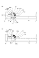
以下、本発明を実施するための形態を、図面に基づいて詳細に説明する。図1は、本発明の第1の実施の形態に係るシート給送装置を備えた画像形成装置の構成を示す図である。図1において、50はレーザビームプリンタ、50Aはレーザビームプリンタ本体(以下、プリンタ本体という)である。プリンタ本体50Aは、画像形成部50Bを備えると共に、プリンタ本体50Aの下部にはトレイ3に積載収納された記録紙等のシートSを画像形成部50Bに給送するシート給送装置1が設けられている。
DESCRIPTION OF EMBODIMENTS Hereinafter, embodiments for carrying out the present invention will be described in detail with reference to the drawings. FIG. 1 is a diagram illustrating a configuration of an image forming apparatus including a sheet feeding device according to a first embodiment of the present invention. In FIG. 1,
画像形成部50Bは、感光体ドラム21aの他、不図示の帯電器、現像スリーブ、クリーナ等を備えたプロセスカートリッジ21を備えている。また、感光体ドラム21aの表面を露光して感光体ドラム21a上に静電潜像を形成する露光手段であるレーザスキャナ20を備えている。また、プリンタ本体50Aは、感光体ドラム21aと当接し、感光体ドラム21aと共に転写部を構成する転写ローラ21b、転写部にて転写されたトナー画像をシートSに定着させる定着部22等を備えている。
In addition to the
シート給送装置1は、シートを積載するシート積載手段としてのトレイ3に積載されたシートSを最上側より給送するシート給送手段としての給送ローラ5と、シートを1枚ずつ分離する分離部30とを備えている。なお、給送ローラ5は、不図示のシート給送装置本体に固定された不図示のステーに保持されている回動軸4を中心に上下に回動可能に支持された回動アーム17の回動端部に回転自在に支持されている。そして、回動アーム17が回動することにより、トレイ3に載置されたシートSの積載高さによらず、最上位シートSaの上面に給送ローラ5が当接する。なお、本実施の形態において、シートSをトレイ3にセットする際、シートSはプリンタ本体50Aの側方(図1におけるプリンタ本体の右側)からトレイ3上に押し込まれてセットされる。
The
次に、このように構成されたレーザビームプリンタ50における画像形成動作について説明する。画像形成動作が開始されると、まず感光体ドラム21aは時計回りに回転して表面が不図示の帯電器により帯電され、この後、感光体ドラム21aに対し、レーザスキャナ20から画像情報に基づいてレーザ光が発光される。これにより、感光体ドラム上には静電潜像が形成される。次に、この静電潜像は、トナーにより現像されてトナー画像として可視化される。
Next, an image forming operation in the
一方、トナー像形成動作に並行してシート給送装置1の給送ローラ5がトレイ3上の最上位のシートSaに当接した状態で回転し、最上位のシートSaを送り出す。そして、給送ローラ5により給送された最上位のシートSaは、分離部30により1枚ずつ分離されて搬送された後、搬送ローラ対23により、転写部に搬送され、転写ローラ21bにより感光体ドラム21aの画像が転写される。次に、トナー画像が転写されたシートSaは、定着部22に搬送され、加熱ローラ22a及び加圧ローラ22bの間を通過することで未定着トナー像が加熱・加圧されてシート表面に定着される。なお、このようにしてトナー像が定着された後のシートSaは、排紙ローラ26により排紙トレイ27上に画像面を下側にして排出される。
On the other hand, in parallel with the toner image forming operation, the
図2は、分離部30の構成を示す図であり、分離部30は、可動壁6と、可動壁6を移動可能に支持する支持部材31,32と、固定壁33と、可動壁6及び固定壁33の間に設けられた圧縮バネである付勢バネ10と、カム7とを備えている。ここで、可動壁6の給送ローラ側には、給送ローラ5により給送されたシートSが押し付けられ、シートを1枚ずつ分離して搬送するための鉛直方向に対して傾いた斜面を備えた分離斜面であるシート突き当て面6bが設けられている。また、シート給送方向に沿って移動可能な分離手段である可動壁6のシート給送方向と直交する幅方向の両側面には、シート給送方向に沿って配置され、可動壁6の移動方向や移動時の姿勢を決めるための2つのボス6aが突設されている。
FIG. 2 is a diagram illustrating a configuration of the
可動壁6を移動可能に支持する支持手段としての支持部材31,32には、それぞれ可動壁6のボス6aが摺動可能な第1及び第2ボス溝9a,9bが形成されている。そして、支持部材31,32は、第1及び第2ボス溝9a,9bを介して可動壁6を移動可能に支持している。なお、本実施の形態において、可動壁6のシート突き当て面6b側に位置する第1ボス溝9aは、図1に示すトレイ3のシート積載面3aと略平行に形成されている。また、ボス溝9aよりもシート給送方向下流側の第2ボス溝9bは、シート給送方向下流側の方が低くなるように傾斜して形成されている。
First and
さらに可動壁6は、通常、可動壁6及び固定壁33の間に設けられた付勢バネ10により、図3の(a)のように可動壁6のボス6aが、第1及び第2ボス溝9a,9bのシート給送方向上流端に当接した待機状態を保つようになっている。なお、可動壁6をシート給送方向と逆方向に付勢する付勢手段としての付勢バネ10のバネ力は、シートがトレイ上にセットされる際、シートが可動壁6と当接することにより、外力Fxがかかっても可動壁6が移動することがない大きさに設定されている。これにより、外力Fxがかかっていない状態、もしくは外力Fxが付勢バネ10の付勢力から得られる付勢バネ作用力Fspより小さい場合は、図3の(a)に示す待機状態を保つことができる。
Further, the
また、可動壁6は、外力Fxが付勢バネ10の付勢バネ作用力Fspよりも大きい場合は、図3の(b)に示すように可動壁6のボス6aを、第1及び第2ボス溝9a,9bに沿って移動させながら、シート給送方向下流側に移動する。ここで、ボス6aが移動すると、案内部としての既述した第1及び第2ボス溝9a,9bにより、可動壁6がシート給送方向下流側への傾斜しながら移動するように案内される。これに伴い、可動壁6のシート突き当て面6bと、トレイ3のシート積載面3aとの角度が変化する。即ち、可動壁6が図3の(a)に示す待機位置から、給送されたシートにより付勢バネ10の付勢力に抗してシート給送方向下流側に移動して図3の(b)に示す状態になると、シート突き当て面6bとシート積載面3aとの角度(傾斜角)がθ1→θ2へ変わる。すなわち、シート突き当て面6bとシート積載面3aの鋭角側の角度が小さくなる(θ1→θ2)ように変更される。
Further, when the external force Fx is larger than the biasing spring acting force Fsp of the biasing
カム7は可動壁6のシート給送方向下流側への移動を規制するものであり、給送ローラ5によるシートの給送が開始されるまでは、可動壁6のシート突き当て面6bとは反対側の面に当接して可動壁6の移動を規制する。なお、給送時には給送ローラ5が回転すると共に、不図示の電気基板から不図示のソレノイドに信号が入力されることにより、ソレノイドが吸引され、ソレノイドが吸引されると、不図示の駆動列から駆動が伝達されてカム7が回転する。そして、このように規制手段としてのカム7が回転することにより、カム7による規制が解除され、これにより、可動壁6は給送ローラ5により給送されたシートが当接すると、シート給送方向下流側への移動が可能になる。
The
図4は、可動壁6に作用する力を示す模式図であり、図4の(a)は本実施の形態における可動壁6に作用する力を示す模式図、図4の(b)は比較参考図である。なお、この比較参考図において、206はシート積載面3aよりも下方に設けられた回動中心206aを支点に回動する可動壁である。この可動壁206の場合、可動壁206のシート突き当て面206bと回動中心206aとの距離(R2)が短いため、シート突き当て面206bの高さ方向の位置によって、付勢バネ10による付勢バネ作用力Fsp1,Fsp2,Fsp3が大きく異なる。
FIG. 4 is a schematic diagram showing the force acting on the
このため、外力Fx1,Fx2,Fx3、すなわち給送ローラ5により給送されたシートが可動壁206に当接する時の力の大きさが同じであっても、シート突き当て面6bの上方側に外力Fx1が作用する場合は可動壁206が移動しやすい。また、シート突き当て面6bの下方側に外力Fx3が作用する場合は可動壁6が移動しにくい。
For this reason, even when the external forces Fx1, Fx2, Fx3, that is, the magnitude of the force when the sheet fed by the feeding
これに対し、本実施の形態のようにボス6aと第1及び第2ボス溝9a,9bとにより、可動壁6の移動を案内する場合、図4の(b)に比べて可動壁6の回動中心をシート積載面3aよりも下方に大きく離れた位置にすることができる。この場合、可動壁6のシート突き当て面6bと回動中心との距離(R1)が長いため、シート突き当て面6bの高さ方向の位置によらず、付勢バネ10による付勢バネ作用力Fsp1,Fsp2,Fsp3の差異を小さくすることができる。これにより、可動壁6が移動する条件としての外力(Fx1、Fx2、Fx3は同じ力)の高さ方向の位置、即ちシートSの積載高さによる外力の変動が小さくなり、安定してシートSを分離することができる。
On the other hand, when the movement of the
図5は、シートの種類に応じた付勢バネ10の付勢バネ作用力Fspと、シートSの搬送力の関係を説明する図である。なお、図5において、縦軸は、可動壁6を待機状態の位置に固定した状況での代表的なシートSの搬送力Fz、すなわち各種シートの剛性等の違いによって生じる、シートSの先端を曲げて搬送するために必要な力を示している。さらに、縦軸は、給送ローラ5から得られる搬送力Fr、付勢バネ10の付勢バネ作用力Fspの大きさを示している。
FIG. 5 is a diagram illustrating the relationship between the urging spring acting force Fsp of the urging
ここで、給送ローラ5の搬送力Frについて図6を用いて説明する。給送ローラ5の搬送力Frは給送ローラ5が回転し食い込むことで発生する垂直抗力Nに給送ローラ5とシートSの摩擦係数を乗じたものである。垂直抗力Nは回動軸4と最上位シートSaの距離h、回動軸4と給送ローラ5の距離L等の条件によって決定する。このうち、距離hはシートSの積載高さによって変化する。また、給送ローラ5とシートSの摩擦係数は給送ローラ5の材質、シートSの種類などの条件より決定する。
Here, the conveying force Fr of the feeding
本実施の形態の場合、シート突き当て面6bの表面は、薄紙(坪量60g/m2)、普通紙(坪量80g/m2)の搬送力Fzが約3N以下になるように設定され、厚紙(坪量160g/m2)、封筒の搬送力Fzが約10N以上となるように設定されている。ここで、給送ローラ5から得られる搬送力Frは、距離hが変化しても略一定となるようにしている。また、搬送力Frを一定の大きさに設定した時の付勢バネ10の付勢バネ作用力Fspの設定は、普通紙、薄紙の搬送力Fzより大きくし、かつ厚紙、封筒の搬送力Fz、給送ローラ5の搬送力Frよりも小さくなるように設定する。このため、本実施の形態においては、上述の条件を満たすために付勢バネ10の付勢バネ作用力Fspは5Nに設定している。
In the case of the present embodiment, the surface of the
次に図7を用いてシート給送装置1のシート給送動作について説明する。図7の(a)は、ユーザがトレイ3にシートSをセットした時の状態を示す図であり、このときカム7はホームポジションにあり、可動壁6のシート突き当て面6bの反対側の面に当接している。これにより、可動壁6の移動は規制され、ユーザがトレイ3にシートSをセットする際、シートSが可動壁6に突き当たっても可動壁6が移動しないため、ユーザは、可動壁6にシートSの先端を突き当てることによりシートSを容易にセットすることができる。つまり、シートをセットする際のセット性を良好にすることができる。
Next, the sheet feeding operation of the
図7の(b)は、坪量60g/m2の薄紙を給送した状態を示している。シートを給送する場合、まず不図示の電気基板からソレノイドに信号が入力されることによりカム7が回転を始めて可動壁6のシート突き当て面6bの反対面から離間し、可動壁6は移動可能な状態となる。
FIG. 7B shows a state where thin paper having a basis weight of 60 g / m 2 is fed. When feeding a sheet, first, when a signal is input from an electric board (not shown) to a solenoid, the
この後、給送ローラ5が回転を始め、給送ローラ5に当接した最上位シートSaを給送すると、付勢バネ10により付勢された可動壁6のシート突き当て面6bに最上位シートSaが押し付けられる。この状態では、可動壁6は給送ローラ5の搬送力Frを受けるものの、薄紙であるため最上位シートSaの先端を曲げて搬送するための搬送力Frは、付勢バネ10の付勢バネ作用力Fspよりも小さいことから、可動壁6が移動することはない。
Thereafter, when the feeding
このように可動壁6が移動しない状態で、さらに可動壁6のシート突き当て面6bに最上位シートSaが押し付けられると、最上位シートSaのシート先端部のみが曲がって給送される。これにより、最上位シートSaは下位シートと分離し、可動壁6のシート突き当て面6bにガイドされて、搬送ローラ対23へ搬送される。
When the uppermost sheet Sa is further pressed against the
この時、下位シートにおいては、下位シートに作用する給送ローラ5の搬送力Frは、シート間の摩擦力を介しているので大きさが足りない。このため、可動壁6のシート突き当て面6bに下位シートの先端が押し当てられても、先端が曲がらず下位シートは搬送されない。よって、下位シートは最上位シートSaに連れ送りされることはなく、重送が発生しない。そして、最上位シートSaが搬送ローラ対23へ搬送された後、カム7は、再び可動壁6のシート突き当て面6bの反対面に当接したホームポジションに達して回転を停止する。
At this time, in the lower sheet, the conveying force Fr of the feeding
図7の(c)は、坪量160g/m2の厚紙を給送した状態を示している。この場合、給送ローラ5の回転により最上位シートSaが搬送され、付勢バネ10により付勢された可動壁6のシート突き当て面6bに押し付けられる。このとき、可動壁6は給送ローラ5の搬送力Frを受けるが、この搬送力Frは、シートが厚紙であり、所定以上の剛性を有するため、最上位シートSaの先端を曲げて搬送するための付勢バネ10の付勢バネ作用力Fspよりも大きい。
FIG. 7C shows a state in which thick paper having a basis weight of 160 g / m 2 is fed. In this case, the uppermost sheet Sa is conveyed by the rotation of the feeding
したがって、最上位シートSaは、先端が曲がることなく可動壁6を押すようになり、可動壁6は第1及び第2ボス溝9a,9bに沿って移動する。そして、可動壁6が移動することにより、その移動量によってシート突き当て面6bとシート積載面3aとの間のなす傾斜角θが減少する。
Accordingly, the uppermost sheet Sa comes to push the
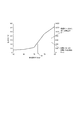
図8は、坪量160g/m2の厚紙を給送する際の搬送力Fzと傾斜角θの関係を示している。傾斜角θが小さくなるほど、シートSの先端を曲げて搬送するための搬送力Fzも小さくなるのがわかる。図8によれば、傾斜角θが約72°に達した時点で、付勢バネ10の付勢力によって可動壁6が移動を停止し、最上位シートSaの先端部が曲がるようになる。この後、最上位シートSaはシート突き当て面6bやガイドに導かれて搬送ローラ対23へと搬送される。
FIG. 8 shows the relationship between the conveying force Fz and the inclination angle θ when feeding thick paper having a basis weight of 160 g / m 2 . It can be seen that the smaller the inclination angle θ, the smaller the conveying force Fz for bending and conveying the leading edge of the sheet S. According to FIG. 8, when the inclination angle θ reaches about 72 °, the
この時、下位シートにおいては、下位シートに作用する給送ローラ5の搬送力Frは、シート間の摩擦力を介しているので搬送力Frが足りず、シート突き当て面6bに下位シートの先端が押し当てられても曲がることなく搬送できない。よって、下位シートは最上位シートSaと共に連れ出されることはなく、重送が発生しない。そして、最上位シートSaが搬送ローラ対23へ搬送された後、カム7は、再び可動壁6のシート突き当て面6bの反対面に当接したホームポジションに達して回転を停止する。
At this time, in the lower sheet, the conveyance force Fr of the feeding
以上説明したように、本実施の形態では、可動壁6を移動可能とすると共に、可動壁6が移動すると、可動壁6が傾斜するようにしている。これにより、搬送力の弱いシートである薄紙から搬送力の強いシートである厚紙や封筒まで幅広い種類のシートを、確実に分離給送することができる。さらに、可動壁6の回動中心をシート積載面3aの下方に大きく離すようにすることにより、シートSの積載高さが変わっても、最上位シートSaに与える付勢バネ10の付勢バネ作用力Fspの変化を小さくすることができる。この結果、シートSの積載高さによって可動壁6の移動する条件の変動を小さくでき、安定したシートの分離給送性能を発揮することができる。
As described above, in the present embodiment, the
本実施の形態のように、シート突き当て面6bを有する可動壁6を、給送ローラ5により給送されたシートと当接して移動すると傾斜するようにすることにより、シートの剛性の大きさにかかわらず、安定してシートを分離して給送することができる。
As in the present embodiment, the
なお、既述したように本実施の形態においては、カム7を設けることにより、ユーザがトレイにシートをセットする際のセット性を良好にすることができるが、カム7を設けない場合でも、安定したシートの分離給送性能を発揮することができる。
As described above, in the present embodiment, by providing the
次に、本発明の第2の実施の形態について説明する。図9、図10は、本実施の形態に係るシート給送装置の構成を説明する図である。なお、図9、図10において、既述した図2及び図3と同一符号は、同一又は相当部分を示している。 Next, a second embodiment of the present invention will be described. 9 and 10 are diagrams illustrating the configuration of the sheet feeding apparatus according to the present embodiment. 9 and 10, the same reference numerals as those in FIGS. 2 and 3 described above indicate the same or corresponding parts.
本実施の形態においては、図9及び図10に示すように第1ボス溝9aが、給送ローラ5から離れるに従い、斜め上方へ傾斜するように形成されている。このように第1ボス溝9aを形成した場合、可動壁6が移動する際、可動壁6のシート突き当て面6bとシート積載面3aとの角度が変化すると共に、可動壁6の移動量によらず、常にシート突き当て面6bの上端が待機状態の位置での高さH6になる。
In the present embodiment, as shown in FIGS. 9 and 10, the
図11の(a)は、本実施の形態において、ユーザがトレイ3にシートSをセットした時の状態を示しており、このとき、可動壁6のシート突き当て面6bの反対側の面にカム7が当接している。図11の(b)は、坪量60g/m2の薄紙を給送した状態を示しており、このときカム7は可動壁6から離間しており、可動壁6は移動可能な状態となる。
FIG. 11A shows a state when the user sets the sheet S on the
この状態で、給送ローラ5が回転を始め、最上位シートSaが給送されると、付勢バネ10により付勢された可動壁6のシート突き当て面6bに最上位シートSaが押し付けられる。このとき、可動壁6は移動可能な状態であり、最上位シートSaを介して給送ローラ5の搬送力Frを受けるが、最上位シートSaは薄紙であるため、先端を曲げて搬送するための搬送力Frは、付勢バネ10の付勢バネ作用力Fspよりも小さい。このため、可動壁6が移動して移動することはない。
In this state, when the feeding
このように可動壁6が動かない状態で、さらに可動壁6のシート突き当て面6bに最上位シートSaが押し付けられると、最上位シートSaのシート先端部のみが曲がって給送されることで最上位シートSaが下位シートと分離する。そして、分離された最上位シートSaは、可動壁6のシート突き当て面6bにガイドされて搬送ローラ対23へ搬送される。
When the uppermost sheet Sa is further pressed against the
この時、下位シートにおいては、下位シートに作用する給送ローラ5の搬送力Frは、シート間の摩擦力を介しているので小さく、可動壁6のシート突き当て面6bに下位シートの先端が押し当てられても曲がらず搬送することができない。よって下位シートは最上位シートSaと共に連れ出されることはなく、重送が発生しない。そして、最上位シートSaが搬送ローラ対23へ搬送された後、カム7は、再び可動壁6のシート突き当て面6bの反対面に当接したホームポジションに達して回転を停止する。
At this time, in the lower sheet, the conveying force Fr of the feeding
図11の(c)は坪量160g/m2の厚紙を給送した状態を示しており、このときカム7は可動壁6から離間しており、可動壁6は移動可能な状態となる。この状態で、給送ローラ5が回転を始め、最上位シートSaが搬送されると、付勢バネ10により付勢された可動壁6のシート突き当て面6bに最上位シートSaが押し付けられる。このとき、可動壁6は移動可能な状態であり、給送ローラ5の搬送力Frを受けるが、厚紙であるため最上位シートSaの先端を曲げて搬送するための搬送力Frは、付勢バネ10の付勢バネ作用力Fspよりも大きい。このため、可動壁6は第1及び第2ボス溝9a,9bに沿って移動する。
FIG. 11 (c) shows a state in which thick paper having a basis weight of 160 g / m 2 is fed. At this time, the
ここで、可動壁6が移動すると、移動量によってシート突き当て面6bとシート積載面3aとの間のなす傾斜角θが変化する。なお、坪量が約160g/m2の厚紙の搬送力Fzと傾斜角θの関係は、既述した図8で示されており、本実施の形態も、これに準ずる。図8によれば傾斜角θが約72°に達した時点で、最上位シートSaの先端部が曲がることになり、この後はシート突き当て面6bや下流側のガイドに導かれて搬送ローラ対23へと搬送される。
Here, when the
この時、下位シートにおいては、下位シートに作用する給送ローラ5の搬送力Frは、シート間の摩擦力を介しているので小さく、シート突き当て面6bに下位シートの先端が押し当てられても曲がることなく搬送することができない。よって下位シートは最上位シートSaと共に連れ出されることはなく、重送が発生しない。そして、最上位シートSaが搬送ローラ対23へ搬送された後、カム7は、再び可動壁6のシート突き当て面6bの反対面に当接したホームポジションに達して回転を停止する。
At this time, in the lower sheet, the conveying force Fr of the feeding
ところで、第1ボス溝9aがシート積載面3aと略平行に形成されている場合、可動壁6が移動して傾くと、既述した図7に示すように、可動壁6のシート突き当て面6bの上端の高さは、待機状態の位置での高さH6よりも移動するに従い低くなっていく。これに対し、本実施の形態においては、第1ボス溝9aは、給送ローラ5から離れるに従い、斜め上方へ傾斜するように形成されている。この場合、可動壁6が移動して傾く際、可動壁6のシート突き当て面6bの上端位置の高さは、傾斜前の待機状態の位置での高さH6よりも低くならない。
By the way, when the
よって、可動壁6の移動量によらず、可動壁6のシート突き当て面6bにより、最上位シートSaの先端を一定の高さまで確実にガイドすることができ、下流側のガイドとの隙間、段差などで搬送不良を起こすことなくシートを送り出すことができる。
Therefore, regardless of the amount of movement of the
以上説明したように、本実施の形態においては、第1ボス溝9aを給送ローラ5から離れるに従い、斜め上方に傾斜するよう形成している。これにより、可動壁6のシート突き当て面6bにシートを押し付けて分離給送する性能を保ちつつ、可動壁6が移動してもシートを確実に送り出すことができる。
As described above, in the present embodiment, the
なお、本実施の形態においては、可動壁6の移動量によらず、常にシート突き当て面6bの上端が待機状態の位置での高さH6になるように構成している。しかし、本実施の形態は、これに限らず、ボス溝9aの形状により、可動壁6を移動するに従い待機状態の位置での高さH6より高くするようにしても良い。このように構成した場合でも、可動壁6が移動しても、可動壁6のシート突き当て面6bにより最上位シートSaの先端を一定の高さ以上に確実にガイドすることができる。
In the present embodiment, the upper end of the
1…シート給送装置、3…トレイ、5…給送ローラ、6…可動壁、6a…ボス、6b…シート突き当て面、7…カム、9a,9b…第1及び第2ボス溝、10…付勢バネ、30…分離部、31,32…支持部材、33…固定壁、50…レーザビームプリンタ、50A…レーザビームプリンタ本体、50B…画像形成部、S…シート、Sa…最上位シート
DESCRIPTION OF
Claims (8)
前記シート積載面に積載されたシートをシート給送方向に給送するシート給送手段と、
前記シート給送手段により給送されたシートと当接してシートを1枚ずつ分離する分離斜面を有し、前記分離斜面が前記シート給送手段によって給送されるシートに押圧されることで前記シート給送方向に沿って移動可能な分離手段と、
前記分離手段を前記シート給送方向と逆方向に付勢する付勢手段と、
前記分離手段の前記シート給送方向下流側への移動に伴って、前記シート積載面と前記分離斜面とのなす鋭角が第1角度から前記第1角度よりも小さい第2角度に変わるように前記分離手段を回動可能に支持する支持手段と、を備え、
前記分離手段の回動中心は、前記シート積載面に対して前記シート給送手段の反対側に位置する、
ことを特徴とするシート給送装置。 A sheet stacking means having a sheet stacking surface of the sheet is Ru are stacked,
Sheet feeding means for feeding the sheets stacked on the sheet stacking surface in a sheet feeding direction ;
A separation slope that contacts the sheet fed by the sheet feeding means and separates the sheets one by one, and the separation slope is pressed by the sheet fed by the sheet feeding means; Separating means movable along the sheet feeding direction;
And biasing means for biasing the separating means to the sheet feeding direction and a reverse direction,
With the movement to the sheet feeding direction downstream side of the pre-Symbol separation means, so as to form an acute angle with said sheet stacking surface and the separation slope changes to a small second angle than the first angle from the first angle Supporting means for rotatably supporting the separating means ,
The center of rotation of the separating unit is located on the opposite side of the sheet feeding unit with respect to the sheet stacking surface.
A sheet feeding apparatus characterized by that.
ことを特徴とする請求項1に記載のシート給送装置。 The sheet feeding apparatus according to claim 1.
ことを特徴とする請求項1又は2に記載のシート給送装置。 The support means includes a guide portion that guides the movement of the separation means while inclining to the downstream side in the sheet feeding direction .
The sheet feeding apparatus according to claim 1 , wherein the sheet feeding apparatus is a sheet feeding apparatus.
ことを特徴とする請求項3に記載のシート給送装置。 The guide part is formed so that the upper end position of the separation slope is not lower than the height of the upper end position before the inclination when the separation means is inclined .
The sheet feeding apparatus according to claim 3 .
前記第1長孔部は、前記シート給送方向に直交するシートの幅方向から視て、第1方向に延び、 The first long hole portion extends in the first direction when viewed from the width direction of the sheet orthogonal to the sheet feeding direction,
前記第2長孔部は、前記幅方向から視て、前記第1方向と異なる第2方向に延びている、 The second long hole portion extends in a second direction different from the first direction as viewed from the width direction.
ことを特徴とする請求項3又は4に記載のシート給送装置。 The sheet feeding apparatus according to claim 3, wherein the sheet feeding apparatus is a sheet feeding apparatus.
ことを特徴とする請求項1乃至5の何れか1項に記載のシート給送装置。 The urging force of the urging means is set to a size such that the separation means moves when a sheet having a rigidity of a predetermined size or more comes into contact with the separation means .
Sheet feeding apparatus according to any one of claims 1 to 5, characterized in that.
ことを特徴とする請求項1乃至6の何れか1項に記載のシート給送装置。 Until the sheet feeding is started by said sheet feeding means, including a restricting means for restricting the movement of the sheet feeding direction downstream side of the separating means and in contact with said separating means,
Sheet feeding apparatus according to any one of claims 1 to 6, characterized in that.
前記シート給送装置から給送されたシートに画像を形成する画像形成部と、を備えた、
ことを特徴とする画像形成装置。 A sheet feeding device according to any one of claims 1 to 7 ,
An image forming unit that forms an image on the sheet fed from the sheet feeding device ,
An image forming apparatus.
Priority Applications (3)
| Application Number | Priority Date | Filing Date | Title |
|---|---|---|---|
| JP2012263766A JP6066695B2 (en) | 2012-11-30 | 2012-11-30 | Sheet feeding apparatus and image forming apparatus |
| US14/084,900 US20140151954A1 (en) | 2012-11-30 | 2013-11-20 | Sheet feeding device and image forming apparatus |
| CN201310607264.9A CN103848237B (en) | 2012-11-30 | 2013-11-26 | Sheet feeding apparatus and imaging device |
Applications Claiming Priority (1)
| Application Number | Priority Date | Filing Date | Title |
|---|---|---|---|
| JP2012263766A JP6066695B2 (en) | 2012-11-30 | 2012-11-30 | Sheet feeding apparatus and image forming apparatus |
Publications (3)
| Publication Number | Publication Date |
|---|---|
| JP2014108859A JP2014108859A (en) | 2014-06-12 |
| JP2014108859A5 JP2014108859A5 (en) | 2016-01-21 |
| JP6066695B2 true JP6066695B2 (en) | 2017-01-25 |
Family
ID=50824687
Family Applications (1)
| Application Number | Title | Priority Date | Filing Date |
|---|---|---|---|
| JP2012263766A Active JP6066695B2 (en) | 2012-11-30 | 2012-11-30 | Sheet feeding apparatus and image forming apparatus |
Country Status (3)
| Country | Link |
|---|---|
| US (1) | US20140151954A1 (en) |
| JP (1) | JP6066695B2 (en) |
| CN (1) | CN103848237B (en) |
Families Citing this family (14)
| Publication number | Priority date | Publication date | Assignee | Title |
|---|---|---|---|---|
| JP6385366B2 (en) * | 2013-12-12 | 2018-09-05 | キヤノン電子株式会社 | Sheet feeding apparatus, image reading apparatus, and image forming apparatus |
| US9573779B2 (en) * | 2014-02-19 | 2017-02-21 | Canon Kabushiki Kaisha | Feeding apparatus and printing apparatus |
| JP2015205762A (en) * | 2014-04-22 | 2015-11-19 | キヤノン株式会社 | Sheet feeder and image formation device |
| JP6525552B2 (en) | 2014-10-29 | 2019-06-05 | キヤノン株式会社 | Sheet feeding apparatus and image forming apparatus |
| JP6122826B2 (en) * | 2014-11-14 | 2017-04-26 | 株式会社小矢部精機 | Sheet material separation assist device |
| JP2017132600A (en) | 2016-01-28 | 2017-08-03 | キヤノン株式会社 | Sheet feeder |
| JP2017195553A (en) | 2016-04-21 | 2017-10-26 | キヤノン株式会社 | Image formation apparatus |
| JP2017194610A (en) | 2016-04-21 | 2017-10-26 | キヤノン株式会社 | Image forming apparatus |
| JP6855229B2 (en) * | 2016-12-14 | 2021-04-07 | キヤノン株式会社 | Seat support device and image forming device |
| JP6929085B2 (en) | 2017-02-21 | 2021-09-01 | キヤノン株式会社 | Sheet feeding device and image forming device |
| JP6921628B2 (en) * | 2017-05-24 | 2021-08-18 | キヤノン株式会社 | Sheet feeding device and image forming device |
| US11192737B2 (en) * | 2019-06-18 | 2021-12-07 | Lexmark International, Inc. | Adjustable compliance of separation strips in a media dam |
| CN110723569B (en) * | 2019-10-15 | 2021-10-15 | 朱笑笑 | Paper filling device for ink-jet printer |
| CN112850240B (en) * | 2021-03-07 | 2022-11-11 | 浙江咨成软件科技有限公司 | Silk flower blade feeding and discharging device matched with bone penetrating machine |
Family Cites Families (18)
| Publication number | Priority date | Publication date | Assignee | Title |
|---|---|---|---|---|
| US5622364A (en) * | 1996-03-27 | 1997-04-22 | Lexmark International, Inc. | Apparatus and method of determining a media level in a supply tray |
| JPH09315606A (en) * | 1996-05-29 | 1997-12-09 | Nec Yonezawa Ltd | Paper feeder |
| US5709381A (en) * | 1996-11-22 | 1998-01-20 | Hewlett-Packard Company | Printer media tray with automatic skewing of stack of media |
| JP3501714B2 (en) * | 2000-03-13 | 2004-03-02 | キヤノン株式会社 | Paper feeder and image forming apparatus having the same |
| JP3997057B2 (en) * | 2000-04-13 | 2007-10-24 | キヤノン株式会社 | Sheet feeding apparatus and image forming apparatus provided with the same |
| JP3689629B2 (en) * | 2000-09-29 | 2005-08-31 | キヤノン株式会社 | Sheet feeding apparatus and sheet processing apparatus |
| KR100426537B1 (en) * | 2002-01-15 | 2004-04-14 | 삼성전자주식회사 | Paper feeding cassette for printer |
| KR100555912B1 (en) * | 2003-06-04 | 2006-03-03 | 삼성전자주식회사 | Printing apparatus and a method for picking up a paper |
| KR100529341B1 (en) * | 2003-08-13 | 2005-11-17 | 삼성전자주식회사 | Printer and paper feeding method of printer |
| US20050242491A1 (en) * | 2004-04-30 | 2005-11-03 | Fujifilm Electronic Imaging Ltd. | Plate feeding apparatus |
| TWI302518B (en) * | 2006-06-26 | 2008-11-01 | Lite On Technology Corp | Object-feeding system |
| JP4844773B2 (en) * | 2009-09-25 | 2011-12-28 | セイコーエプソン株式会社 | Recording medium feeding device |
| JP5484017B2 (en) * | 2009-11-27 | 2014-05-07 | キヤノン株式会社 | Paper feeding device and image forming apparatus having the same |
| JP5440160B2 (en) * | 2009-12-25 | 2014-03-12 | セイコーエプソン株式会社 | Loading device, conveying device, and recording device |
| JP5703655B2 (en) * | 2010-09-22 | 2015-04-22 | セイコーエプソン株式会社 | Conveying apparatus and recording apparatus |
| US8910932B2 (en) * | 2011-06-30 | 2014-12-16 | Hewlett-Packard Development Company, L.P. | Separator assembly for use with printers |
| JP5854696B2 (en) * | 2011-08-18 | 2016-02-09 | キヤノン株式会社 | Paper feeding device and recording device |
| JP5835000B2 (en) * | 2012-02-27 | 2015-12-24 | セイコーエプソン株式会社 | Recording medium feeding apparatus and recording apparatus |
-
2012
- 2012-11-30 JP JP2012263766A patent/JP6066695B2/en active Active
-
2013
- 2013-11-20 US US14/084,900 patent/US20140151954A1/en not_active Abandoned
- 2013-11-26 CN CN201310607264.9A patent/CN103848237B/en active Active
Also Published As
| Publication number | Publication date |
|---|---|
| US20140151954A1 (en) | 2014-06-05 |
| CN103848237B (en) | 2016-08-24 |
| JP2014108859A (en) | 2014-06-12 |
| CN103848237A (en) | 2014-06-11 |
Similar Documents
| Publication | Publication Date | Title |
|---|---|---|
| JP6066695B2 (en) | Sheet feeding apparatus and image forming apparatus | |
| US9856099B2 (en) | Sheet feeder and image forming apparatus incorporating the sheet feeder | |
| JP6137838B2 (en) | Sheet feeding apparatus and image forming apparatus | |
| JP6206014B2 (en) | Image forming apparatus and image forming system | |
| JP2006008380A (en) | Sheet feeder | |
| JP4006432B2 (en) | Sheet feeding apparatus and image forming apparatus | |
| JP2008213998A (en) | Sheet feeding device, and image forming device | |
| JP2020007061A (en) | Paper feeder, and image forming apparatus provided with the same | |
| US8398072B2 (en) | Sheet feeding apparatus and image forming apparatus | |
| JP4484762B2 (en) | Sheet separating / conveying mechanism and sheet conveying apparatus including the same | |
| JP2007217125A (en) | Image forming device | |
| US20050001372A1 (en) | Sheet feeding apparatus and image forming apparatus | |
| JP2018080047A (en) | Sheet transport device and image formation device | |
| JP5929475B2 (en) | Image forming apparatus | |
| JP2011207617A (en) | Paper feeder and image forming apparatus | |
| JP2006115031A (en) | Reader and image forming apparatus equipped with the same reader | |
| JP5959931B2 (en) | Sheet feeding apparatus and image forming apparatus | |
| JP4569907B2 (en) | Medium conveying apparatus and image forming apparatus | |
| JP4966882B2 (en) | Paper feeding device and image forming apparatus | |
| JP2014227254A (en) | Sheet feeding device and image formation device | |
| JP2009007087A (en) | Image forming device | |
| JP5791398B2 (en) | Sheet feeding apparatus and image forming apparatus | |
| JP2008213997A (en) | Sheet feeder, image forming device, and image reading device | |
| JP2020111397A (en) | Sheet feeder and image forming apparatus | |
| JP2008239333A (en) | Sheet feeding device, image forming device and image reading device |
Legal Events
| Date | Code | Title | Description |
|---|---|---|---|
| A521 | Written amendment |
Free format text: JAPANESE INTERMEDIATE CODE: A523 Effective date: 20151126 |
|
| A621 | Written request for application examination |
Free format text: JAPANESE INTERMEDIATE CODE: A621 Effective date: 20151126 |
|
| A977 | Report on retrieval |
Free format text: JAPANESE INTERMEDIATE CODE: A971007 Effective date: 20160829 |
|
| A131 | Notification of reasons for refusal |
Free format text: JAPANESE INTERMEDIATE CODE: A131 Effective date: 20160906 |
|
| A521 | Written amendment |
Free format text: JAPANESE INTERMEDIATE CODE: A523 Effective date: 20161104 |
|
| TRDD | Decision of grant or rejection written | ||
| A01 | Written decision to grant a patent or to grant a registration (utility model) |
Free format text: JAPANESE INTERMEDIATE CODE: A01 Effective date: 20161122 |
|
| A61 | First payment of annual fees (during grant procedure) |
Free format text: JAPANESE INTERMEDIATE CODE: A61 Effective date: 20161220 |
|
| R151 | Written notification of patent or utility model registration |
Ref document number: 6066695 Country of ref document: JP Free format text: JAPANESE INTERMEDIATE CODE: R151 |