JP6065826B2 - Tapered roller bearings - Google Patents
Tapered roller bearings Download PDFInfo
- Publication number
- JP6065826B2 JP6065826B2 JP2013267846A JP2013267846A JP6065826B2 JP 6065826 B2 JP6065826 B2 JP 6065826B2 JP 2013267846 A JP2013267846 A JP 2013267846A JP 2013267846 A JP2013267846 A JP 2013267846A JP 6065826 B2 JP6065826 B2 JP 6065826B2
- Authority
- JP
- Japan
- Prior art keywords
- inner ring
- tapered roller
- diameter
- raceway surface
- roller bearing
- Prior art date
- Legal status (The legal status is an assumption and is not a legal conclusion. Google has not performed a legal analysis and makes no representation as to the accuracy of the status listed.)
- Active
Links
- 230000002093 peripheral effect Effects 0.000 claims description 80
- 229920005989 resin Polymers 0.000 claims description 30
- 239000011347 resin Substances 0.000 claims description 30
- 230000036316 preload Effects 0.000 description 8
- 239000003638 chemical reducing agent Substances 0.000 description 7
- 230000000052 comparative effect Effects 0.000 description 6
- 238000003780 insertion Methods 0.000 description 6
- 230000037431 insertion Effects 0.000 description 6
- 230000009467 reduction Effects 0.000 description 6
- 239000004696 Poly ether ether ketone Substances 0.000 description 4
- 239000004734 Polyphenylene sulfide Substances 0.000 description 4
- 229920002530 polyetherether ketone Polymers 0.000 description 4
- 229920000069 polyphenylene sulfide Polymers 0.000 description 4
- 239000011342 resin composition Substances 0.000 description 4
- 239000007787 solid Substances 0.000 description 4
- 238000010521 absorption reaction Methods 0.000 description 3
- 230000000694 effects Effects 0.000 description 3
- 238000005096 rolling process Methods 0.000 description 3
- XLYOFNOQVPJJNP-UHFFFAOYSA-N water Substances O XLYOFNOQVPJJNP-UHFFFAOYSA-N 0.000 description 3
- 239000004760 aramid Substances 0.000 description 2
- 229920003235 aromatic polyamide Polymers 0.000 description 2
- 230000005540 biological transmission Effects 0.000 description 2
- 230000008859 change Effects 0.000 description 2
- 230000005489 elastic deformation Effects 0.000 description 2
- 230000006872 improvement Effects 0.000 description 2
- 238000001746 injection moulding Methods 0.000 description 2
- 239000000463 material Substances 0.000 description 2
- 230000004048 modification Effects 0.000 description 2
- 238000012986 modification Methods 0.000 description 2
- 229920006111 poly(hexamethylene terephthalamide) Polymers 0.000 description 2
- 239000012783 reinforcing fiber Substances 0.000 description 2
- 238000004381 surface treatment Methods 0.000 description 2
- 238000012360 testing method Methods 0.000 description 2
- 229920000049 Carbon (fiber) Polymers 0.000 description 1
- 229920003189 Nylon 4,6 Polymers 0.000 description 1
- 229920002302 Nylon 6,6 Polymers 0.000 description 1
- 229920006153 PA4T Polymers 0.000 description 1
- 229920006121 Polyxylylene adipamide Polymers 0.000 description 1
- 239000006087 Silane Coupling Agent Substances 0.000 description 1
- 229910000831 Steel Inorganic materials 0.000 description 1
- 229920006231 aramid fiber Polymers 0.000 description 1
- 239000004917 carbon fiber Substances 0.000 description 1
- 238000005256 carbonitriding Methods 0.000 description 1
- 238000005255 carburizing Methods 0.000 description 1
- 239000003795 chemical substances by application Substances 0.000 description 1
- 238000010276 construction Methods 0.000 description 1
- 229920006038 crystalline resin Polymers 0.000 description 1
- 238000013461 design Methods 0.000 description 1
- 239000002657 fibrous material Substances 0.000 description 1
- 239000003365 glass fiber Substances 0.000 description 1
- 238000010438 heat treatment Methods 0.000 description 1
- 238000002347 injection Methods 0.000 description 1
- 239000007924 injection Substances 0.000 description 1
- 230000010354 integration Effects 0.000 description 1
- 238000012423 maintenance Methods 0.000 description 1
- 230000014759 maintenance of location Effects 0.000 description 1
- VNWKTOKETHGBQD-UHFFFAOYSA-N methane Chemical compound C VNWKTOKETHGBQD-UHFFFAOYSA-N 0.000 description 1
- 229920006128 poly(nonamethylene terephthalamide) Polymers 0.000 description 1
- 238000004513 sizing Methods 0.000 description 1
- 239000010959 steel Substances 0.000 description 1
- 238000003860 storage Methods 0.000 description 1
- 229920005992 thermoplastic resin Polymers 0.000 description 1
- 230000009466 transformation Effects 0.000 description 1
- 230000037303 wrinkles Effects 0.000 description 1
Images


Description
本発明は、円錐ころ軸受、特に、自動車、鉄道車両、建設機械、産業用ロボットの関節部、工作機械、搬送装置、組立装置等に好適に使用可能な円錐ころ軸受に関する。 The present invention relates to a tapered roller bearing, and more particularly to a tapered roller bearing that can be suitably used for automobiles, railway vehicles, construction machines, joints of industrial robots, machine tools, conveying devices, assembling devices, and the like.
従来、モーメント剛性を必要とする場合に選定される転がり軸受としては、アンギュラ玉軸受が考えられる。 Conventionally, as a rolling bearing selected when moment rigidity is required, an angular ball bearing can be considered.
また、円錐ころ軸受として、保持器のポケットの外周側および内周側の開口縁部に、突部を設けて、ころと保持器とを一体化して、軸受組込み時や使用中のころの脱落を防止し、また、内輪の小鍔を不要とし、その分だけころ長さを長くすることで、負荷容量を大きくしたものが知られている(例えば、特許文献1参照)。 In addition, as a tapered roller bearing, protrusions are provided at the opening edge on the outer and inner peripheral sides of the cage pocket, so that the rollers and the cage are integrated, and the rollers fall off when the bearing is installed or in use. It is also known that the load capacity is increased by making the roller length longer by the length of the inner ring, which eliminates the need for a small inner ring (see, for example, Patent Document 1).
しかしながら、アンギュラ玉軸受において、さらなる高モーメント剛性や長寿命の要求に対応するには、軸受サイズが大きくなってしまい、軸受サイズの維持又は縮小という要求に対応する為には、限界がある。
更に、最近、変速機用として使用される軸受では、高負荷容量で、かつ、変速機のコンパクト化を対応できるもの、つまり、軸受サイズを変更することなく、従来と同等以上の機能であることが求められる。
However, in the angular ball bearing, in order to meet the demand for higher moment rigidity and longer life, the bearing size becomes large, and there is a limit to meet the demand for maintaining or reducing the bearing size.
Furthermore, recently, a bearing used for a transmission has a high load capacity and can cope with the downsizing of the transmission, that is, has a function equal to or higher than that of a conventional one without changing the bearing size. Is required.
一方、特許文献1に記載の円錐ころ軸受では、接触角について考慮されておらず、図示された円錐ころ軸受の接触角では、ラジアル剛性は高いが、高モーメント剛性が得られないと考えられる。
また、特許文献1には、保持器へのころの挿入性に関する検討がなかった。さらに、特許文献1に記載の円錐ころ軸受に使用される保持器は、ころと保持器とが一体化されているが、円錐ころを保持するためのかかり代に対する記載がない為、円錐ころを保持する性能が十分であるか不明である。更に、この円錐ころ軸受では接触角が35°未満であり、仮に、接触角を35°以上に設定すると、内輪には小鍔がない為、保持器だけでころを十分に保持できないことが懸念される。
On the other hand, in the tapered roller bearing described in
Further,
本発明は、前述した課題に鑑みてなされたものであり、その目的は、高モーメント剛性および長寿命を実現した円錐ころ軸受を提供することにある。 The present invention has been made in view of the above-described problems, and an object of the present invention is to provide a tapered roller bearing that achieves high moment rigidity and long life.
本発明の上記目的は、下記の構成により達成される。
(1) 内周面に外輪軌道面を有する外輪と、外周面に内輪軌道面を有する内輪と、前記外輪軌道面と前記内輪軌道面との間に転動自在に配置される複数の円錐ころと、を備える円錐ころ軸受であって、
前記内輪の大径側端部には大鍔が形成され、且つ、前記内輪軌道面は、前記内輪の小径側端面まで連続しており、
接触角αが45°であり、
前記円錐ころのころ大径Dw1と径方向断面肉厚Hの比が0.3<Dw1/H<0.6であることを特徴とする円錐ころ軸受。
(2) 内周面に外輪軌道面を有する外輪と、外周面に内輪軌道面を有する内輪と、前記外輪軌道面と前記内輪軌道面との間に転動自在に配置される複数の円錐ころと、を備える円錐ころ軸受であって、
前記内輪の大径側端部には大鍔が形成され、且つ、前記内輪軌道面は、前記内輪の小径側端面まで連続しており、
接触角αが35°〜55°であり、
前記円錐ころのころ大径Dw1と径方向断面肉厚Hの比が0.3<Dw1/H<0.6であることを特徴とする円錐ころ軸受。
(3) 内周面に外輪軌道面を有する外輪と、外周面に内輪軌道面を有する内輪と、前記外輪軌道面と前記内輪軌道面との間に転動自在に配置される複数の円錐ころと、を備える円錐ころ軸受であって、
前記内輪は、大径側端部と小径側端部のうち、該大径側端部のみに大鍔が形成され、
接触角αが35°〜55°であり、
前記円錐ころのころ大径Dw1と径方向断面肉厚Hの比が0.3<Dw1/H<0.6であることを特徴とする円錐ころ軸受。
(4) ころ長さLwと内輪幅Bの比が0.8<Lw/B<1.2であることを特徴とする(1)〜(3)のいずれかに記載の円錐ころ軸受。
(5) 径方向断面肉厚Hと内径dの比が0.05<H/d<0.15であることを特徴とする(1)〜(4)のいずれかに記載の円錐ころ軸受。
(6) 前記円錐ころ軸受の内径をd、内輪外径をD1としたとき、内輪大鍔側高さ(D1-d)/2と径方向断面肉厚Hの比が0.7<(D1-d)/2H<0.9であることを特徴とする(1)〜(5)のいずれかに記載の円錐ころ軸受。
(7) 軸方向に離間した大径リング部及び小径リング部と、該大径リング部及び小径リング部との間を繋ぐ複数の柱部と、を有し、前記複数の円錐ころを収容保持する複数のポケットを画成する樹脂製保持器をさらに備え、
前記柱部は、前記ポケットの内径側の少なくとも一部において、0.1mm〜0.7mmのかかり代とし、前記ポケットの内径側開口幅が前記円錐ころのころ大径より狭くなるように形成され、且つ、
前記ポケットの外径側の少なくとも一部において、0.1mm〜0.6mmのかかり代とし、前記ポケットの外径側開口幅が前記円錐ころのころ小径より狭くなるように形成されることを特徴とする(1)〜(6)のいずれかに記載の円錐ころ軸受。
(8) 前記保持器の傾斜角度は、32°30´以上55°未満に設定されることを特徴とする(7)に記載の円錐ころ軸受。
(9) 前記大径リング部の内周面と、前記小径リング部の外周面との少なくとも一方には、該リング部の肉厚が前記柱部の肉厚よりも薄くなるように環状の切欠き部が形成されることを特徴とする(7)又は(8)に記載の円錐ころ軸受。
(10) 前記環状の切欠き部は、前記大径リング部の内周面に形成され、
前記環状の切欠き部には、前記大鍔が入り込んでいることを特徴とする(9)に記載の円錐ころ軸受。
(11) 内周面に外輪軌道面を有する外輪と、外周面に内輪軌道面を有する内輪と、前記外輪軌道面と前記内輪軌道面との間に転動自在に配置される複数の円錐ころと、を備える円錐ころ軸受であって、
前記内輪の大径側端部には大鍔が形成され、且つ、前記内輪軌道面は、前記内輪の小径側端面まで連続しており、
接触角αが45°であり、
ころ長さLwと内輪幅Bの比が0.8<Lw/B<1.2であることを特徴とする円錐ころ軸受。
(12) 内周面に外輪軌道面を有する外輪と、外周面に内輪軌道面を有する内輪と、前記外輪軌道面と前記内輪軌道面との間に転動自在に配置される複数の円錐ころと、を備える円錐ころ軸受であって、
前記内輪の大径側端部には大鍔が形成され、且つ、前記内輪軌道面は、前記内輪の小径側端面まで連続しており、
接触角αが35°〜55°であり、
ころ長さLwと内輪幅Bの比が0.8<Lw/B<1.2であることを特徴とする円錐ころ軸受。
(13) 内周面に外輪軌道面を有する外輪と、外周面に内輪軌道面を有する内輪と、前記外輪軌道面と前記内輪軌道面との間に転動自在に配置される複数の円錐ころと、を備える円錐ころ軸受であって、
前記内輪は、大径側端部と小径側端部のうち、該大径側端部のみに大鍔が形成され、
接触角αが35°〜55°であり、
ころ長さLwと内輪幅Bの比が0.8<Lw/B<1.2であることを特徴とする円錐ころ軸受。
(14) 径方向断面肉厚Hと内径dの比が0.05<H/d<0.15であることを特徴とする(11)〜(13)のいずれかに記載の円錐ころ軸受。
(15) 前記円錐ころ軸受の内径をd、内輪外径をD1としたとき、内輪大鍔側高さ(D1-d)/2と径方向断面肉厚Hの比が0.7<(D1-d)/2H<0.9であることを特徴とする(11)〜(14)のいずれかに記載の円錐ころ軸受。
(16) 軸方向に離間した大径リング部及び小径リング部と、該大径リング部及び小径リング部との間を繋ぐ複数の柱部と、を有し、前記複数の円錐ころを収容保持する複数のポケットを画成する樹脂製保持器をさらに備え、
前記柱部は、前記ポケットの内径側の少なくとも一部において、0.1mm〜0.7mmのかかり代とし、前記ポケットの内径側開口幅が前記円錐ころのころ大径より狭くなるように形成され、且つ、
前記ポケットの外径側の少なくとも一部において、0.1mm〜0.6mmのかかり代とし、前記ポケットの外径側開口幅が前記円錐ころのころ小径より狭くなるように形成されることを特徴とする(11)〜(15)のいずれかに記載の円錐ころ軸受。
(17) 内周面に外輪軌道面を有する外輪と、外周面に内輪軌道面を有する内輪と、前記外輪軌道面と前記内輪軌道面との間に転動自在に配置される複数の円錐ころと、を備える円錐ころ軸受であって、
前記内輪の大径側端部には大鍔が形成され、且つ、前記内輪軌道面は、前記内輪の小径側端面まで連続しており、
接触角αが45°であり、
径方向断面肉厚Hと内径dの比が0.05<H/d<0.15であることを特徴とする円錐ころ軸受。
(18) 内周面に外輪軌道面を有する外輪と、外周面に内輪軌道面を有する内輪と、前記外輪軌道面と前記内輪軌道面との間に転動自在に配置される複数の円錐ころと、を備える円錐ころ軸受であって、
前記内輪の大径側端部には大鍔が形成され、且つ、前記内輪軌道面は、前記内輪の小径側端面まで連続しており、
接触角αが35°〜55°であり、
径方向断面肉厚Hと内径dの比が0.05<H/d<0.15であることを特徴とする円錐ころ軸受。
(19) 内周面に外輪軌道面を有する外輪と、外周面に内輪軌道面を有する内輪と、前記外輪軌道面と前記内輪軌道面との間に転動自在に配置される複数の円錐ころと、を備える円錐ころ軸受であって、
前記内輪は、大径側端部と小径側端部のうち、該大径側端部のみに大鍔が形成され、
接触角αが35°〜55°であり、
径方向断面肉厚Hと内径dの比が0.05<H/d<0.15であることを特徴とする円錐ころ軸受。
(20) 前記円錐ころ軸受の内径をd、内輪外径をD1としたとき、内輪大鍔側高さ(D1-d)/2と径方向断面肉厚Hの比が0.7<(D1-d)/2H<0.9であることを特徴とする(17)〜(19)のいずれかに記載の円錐ころ軸受。
(21) 軸方向に離間した大径リング部及び小径リング部と、該大径リング部及び小径リング部との間を繋ぐ複数の柱部と、を有し、前記複数の円錐ころを収容保持する複数のポケットを画成する樹脂製保持器をさらに備え、
前記柱部は、前記ポケットの内径側の少なくとも一部において、0.1mm〜0.7mmのかかり代とし、前記ポケットの内径側開口幅が前記円錐ころのころ大径より狭くなるように形成され、且つ、
前記ポケットの外径側の少なくとも一部において、0.1mm〜0.6mmのかかり代とし、前記ポケットの外径側開口幅が前記円錐ころのころ小径より狭くなるように形成されることを特徴とする(17)〜(20)のいずれかに記載の円錐ころ軸受。
(22) 内周面に外輪軌道面を有する外輪と、外周面に内輪軌道面を有する内輪と、前記外輪軌道面と前記内輪軌道面との間に転動自在に配置される複数の円錐ころと、を備える円錐ころ軸受であって、
前記内輪の大径側端部には大鍔が形成され、且つ、前記内輪軌道面は、前記内輪の小径側端面まで連続しており、
接触角αが45°であり、
前記円錐ころ軸受の内径をd、内輪外径をD1としたとき、内輪大鍔側高さ(D1-d
)/2と径方向断面肉厚Hの比が0.7<(D1-d)/2H<0.9であることを特徴とする円錐ころ軸受。
(23) 内周面に外輪軌道面を有する外輪と、外周面に内輪軌道面を有する内輪と、前記外輪軌道面と前記内輪軌道面との間に転動自在に配置される複数の円錐ころと、を備える円錐ころ軸受であって、
前記内輪の大径側端部には大鍔が形成され、且つ、前記内輪軌道面は、前記内輪の小径側端面まで連続しており、
接触角αが35°〜55°であり、
前記円錐ころ軸受の内径をd、内輪外径をD1としたとき、内輪大鍔側高さ(D1-d
)/2と径方向断面肉厚Hの比が0.7<(D1-d)/2H<0.9であることを特徴とする円錐ころ軸受。
(24) 内周面に外輪軌道面を有する外輪と、外周面に内輪軌道面を有する内輪と、前記外輪軌道面と前記内輪軌道面との間に転動自在に配置される複数の円錐ころと、を備える円錐ころ軸受であって、
前記内輪は、大径側端部と小径側端部のうち、該大径側端部のみに大鍔が形成され、
接触角αが35°〜55°であり、
前記円錐ころ軸受の内径をd、内輪外径をD1としたとき、内輪大鍔側高さ(D1-d
)/2と径方向断面肉厚Hの比が0.7<(D1-d)/2H<0.9であることを特徴とする円錐ころ軸受。
(25) 軸方向に離間した大径リング部及び小径リング部と、該大径リング部及び小径リング部との間を繋ぐ複数の柱部と、を有し、前記複数の円錐ころを収容保持する複数のポケットを画成する樹脂製保持器をさらに備え、
前記柱部は、前記ポケットの内径側の少なくとも一部において、0.1mm〜0.7mmのかかり代とし、前記ポケットの内径側開口幅が前記円錐ころのころ大径より狭くなるように形成され、且つ、
前記ポケットの外径側の少なくとも一部において、0.1mm〜0.6mmのかかり代とし、前記ポケットの外径側開口幅が前記円錐ころのころ小径より狭くなるように形成されることを特徴とする(22)〜(24)のいずれかに記載の円錐ころ軸受。
(26) 内周面に外輪軌道面を有する外輪と、外周面に内輪軌道面を有する内輪と、前記外輪軌道面と前記内輪軌道面との間に転動自在に配置される複数の円錐ころと、を備える円錐ころ軸受であって、
前記内輪の大径側端部には大鍔が形成され、且つ、前記内輪軌道面は、前記内輪の小径側端面まで連続しており、
接触角αが45°であり、
軸方向に離間した大径リング部及び小径リング部と、該大径リング部及び小径リング部との間を繋ぐ複数の柱部と、を有し、前記複数の円錐ころを収容保持する複数のポケットを画成する樹脂製保持器をさらに備え、
前記柱部は、前記ポケットの内径側の少なくとも一部において、0.1mm〜0.7mmのかかり代とし、前記ポケットの内径側開口幅が前記円錐ころのころ大径より狭くなるように形成され、且つ、
前記ポケットの外径側の少なくとも一部において、0.1mm〜0.6mmのかかり代とし、前記ポケットの外径側開口幅が前記円錐ころのころ小径より狭くなるように形成されることを特徴とする円錐ころ軸受。
(27) 内周面に外輪軌道面を有する外輪と、外周面に内輪軌道面を有する内輪と、前記外輪軌道面と前記内輪軌道面との間に転動自在に配置される複数の円錐ころと、を備える円錐ころ軸受であって、
前記内輪の大径側端部には大鍔が形成され、且つ、前記内輪軌道面は、前記内輪の小径側端面まで連続しており、
接触角αが35°〜55°であり、
軸方向に離間した大径リング部及び小径リング部と、該大径リング部及び小径リング部との間を繋ぐ複数の柱部と、を有し、前記複数の円錐ころを収容保持する複数のポケットを画成する樹脂製保持器をさらに備え、
前記柱部は、前記ポケットの内径側の少なくとも一部において、0.1mm〜0.7mmのかかり代とし、前記ポケットの内径側開口幅が前記円錐ころのころ大径より狭くなるように形成され、且つ、
前記ポケットの外径側の少なくとも一部において、0.1mm〜0.6mmのかかり代とし、前記ポケットの外径側開口幅が前記円錐ころのころ小径より狭くなるように形成されることを特徴とする円錐ころ軸受。
(28) 内周面に外輪軌道面を有する外輪と、外周面に内輪軌道面を有する内輪と、前記外輪軌道面と前記内輪軌道面との間に転動自在に配置される複数の円錐ころと、を備える円錐ころ軸受であって、
前記内輪は、大径側端部と小径側端部のうち、該大径側端部のみに大鍔が形成され、
接触角αが35°〜55°であり、
軸方向に離間した大径リング部及び小径リング部と、該大径リング部及び小径リング部との間を繋ぐ複数の柱部と、を有し、前記複数の円錐ころを収容保持する複数のポケットを画成する樹脂製保持器をさらに備え、
前記柱部は、前記ポケットの内径側の少なくとも一部において、0.1mm〜0.7mmのかかり代とし、前記ポケットの内径側開口幅が前記円錐ころのころ大径より狭くなるように形成され、且つ、
前記ポケットの外径側の少なくとも一部において、0.1mm〜0.6mmのかかり代とし、前記ポケットの外径側開口幅が前記円錐ころのころ小径より狭くなるように形成されることを特徴とする円錐ころ軸受。
The above object of the present invention can be achieved by the following constitution.
(1) An outer ring having an outer ring raceway surface on an inner peripheral surface, an inner ring having an inner ring raceway surface on an outer peripheral surface, and a plurality of tapered rollers disposed so as to be freely rollable between the outer ring raceway surface and the inner ring raceway surface. A tapered roller bearing comprising:
A large collar is formed at the large diameter side end of the inner ring, and the inner ring raceway surface continues to the small diameter side end surface of the inner ring,
Contact angle α is Ri 45 ° der,
The tapered roller bearing characterized in that a ratio of the roller large diameter Dw1 of the tapered roller to the radial cross-sectional thickness H is 0.3 <Dw1 / H <0.6 .
(2) An outer ring having an outer ring raceway surface on an inner peripheral surface, an inner ring having an inner ring raceway surface on an outer peripheral surface, and a plurality of tapered rollers disposed so as to be freely rollable between the outer ring raceway surface and the inner ring raceway surface. A tapered roller bearing comprising:
A large collar is formed at the large diameter side end of the inner ring, and the inner ring raceway surface continues to the small diameter side end surface of the inner ring,
The contact angle α is 35 ° to 55 °,
The tapered roller bearing characterized in that a ratio of the roller large diameter Dw1 of the tapered roller to the radial cross-sectional thickness H is 0.3 <Dw1 / H <0.6 .
(3) An outer ring having an outer ring raceway surface on an inner peripheral surface, an inner ring having an inner ring raceway surface on an outer peripheral surface, and a plurality of tapered rollers disposed so as to be freely rollable between the outer ring raceway surface and the inner ring raceway surface. A tapered roller bearing comprising:
The inner ring has a large collar formed only at the large-diameter side end of the large-diameter side end and the small-diameter side end,
The contact angle α is 35 ° to 55 °,
The tapered roller bearing characterized in that a ratio of the roller large diameter Dw1 of the tapered roller to the radial cross-sectional thickness H is 0.3 <Dw1 / H <0.6 .
(4) The tapered roller bearing according to any one of (1) to (3) , wherein the ratio of the roller length Lw to the inner ring width B is 0.8 <Lw / B <1.2.
(5) The tapered roller bearing according to any one of (1) to (4) , wherein the ratio of the radial cross-sectional thickness H to the inner diameter d is 0.05 <H / d <0.15.
(6) When the inner diameter of the tapered roller bearing is d and the outer diameter of the inner ring is D1, the ratio of the inner ring large collar side height (D1-d) / 2 to the radial cross-sectional thickness H is 0.7 <(D1 (d) / 2H <0.9, The tapered roller bearing according to any one of (1) to (5).
(7) A large-diameter ring portion and a small-diameter ring portion that are separated in the axial direction, and a plurality of column portions that connect between the large-diameter ring portion and the small-diameter ring portion, and accommodate and hold the plurality of tapered rollers Further comprising a resin cage that defines a plurality of pockets,
The column portion is formed with a margin of 0.1 mm to 0.7 mm in at least a part of the inner diameter side of the pocket, and the inner diameter side opening width of the pocket is narrower than the large diameter of the tapered roller. ,and,
At least a part of the outer diameter side of the pocket has a margin of 0.1 mm to 0.6 mm, and the opening diameter of the outer diameter side of the pocket is narrower than the small diameter of the tapered roller. The tapered roller bearing according to any one of (1) to (6).
(8) The tapered roller bearing according to (7), wherein an inclination angle of the cage is set to 32 ° 30 ′ or more and less than 55 °.
(9) before the inner peripheral surface of the Kidai径ring portion, at least one of the outer peripheral surface of the small-diameter ring portion, annular as the thickness of the ring portion is thinner than the thickness of the pillar portion The tapered roller bearing according to (7) or (8) , wherein a notch is formed.
(10) The annular notch is formed on an inner peripheral surface of the large-diameter ring part,
The tapered roller bearing according to (9) , wherein the large collar is inserted into the annular notch.
(11) An outer ring having an outer ring raceway surface on an inner peripheral surface, an inner ring having an inner ring raceway surface on an outer peripheral surface, and a plurality of tapered rollers disposed so as to roll between the outer ring raceway surface and the inner ring raceway surface. A tapered roller bearing comprising:
A large collar is formed at the large diameter side end of the inner ring, and the inner ring raceway surface continues to the small diameter side end surface of the inner ring,
The contact angle α is 45 °,
A tapered roller bearing characterized in that the ratio of the roller length Lw to the inner ring width B is 0.8 <Lw / B <1.2.
(12) An outer ring having an outer ring raceway surface on an inner peripheral surface, an inner ring having an inner ring raceway surface on an outer peripheral surface, and a plurality of tapered rollers arranged so as to be freely rollable between the outer ring raceway surface and the inner ring raceway surface. A tapered roller bearing comprising:
A large collar is formed at the large diameter side end of the inner ring, and the inner ring raceway surface continues to the small diameter side end surface of the inner ring,
The contact angle α is 35 ° to 55 °,
A tapered roller bearing characterized in that the ratio of the roller length Lw to the inner ring width B is 0.8 <Lw / B <1.2.
(13) An outer ring having an outer ring raceway surface on an inner peripheral surface, an inner ring having an inner ring raceway surface on an outer peripheral surface, and a plurality of tapered rollers disposed so as to be freely rollable between the outer ring raceway surface and the inner ring raceway surface. A tapered roller bearing comprising:
The inner ring has a large collar formed only at the large-diameter side end of the large-diameter side end and the small-diameter side end,
The contact angle α is 35 ° to 55 °,
A tapered roller bearing characterized in that the ratio of the roller length Lw to the inner ring width B is 0.8 <Lw / B <1.2.
( 14) The tapered roller bearing according to any one of (11) to (13), wherein the ratio of the radial cross-sectional thickness H to the inner diameter d is 0.05 <H / d <0.15.
(15) When the inner diameter of the tapered roller bearing is d and the outer diameter of the inner ring is D1, the ratio of the inner ring large collar side height (D1-d) / 2 to the radial cross-sectional thickness H is 0.7 <(D1 -d) / 2H <0.9, The tapered roller bearing according to any one of (11) to (14).
(16) A large-diameter ring portion and a small-diameter ring portion that are separated in the axial direction, and a plurality of column portions that connect between the large-diameter ring portion and the small-diameter ring portion, and accommodate and hold the plurality of tapered rollers Further comprising a resin cage that defines a plurality of pockets,
The column portion is formed with a margin of 0.1 mm to 0.7 mm in at least a part of the inner diameter side of the pocket, and the inner diameter side opening width of the pocket is narrower than the large diameter of the tapered roller. ,and,
At least a part of the outer diameter side of the pocket has a margin of 0.1 mm to 0.6 mm, and the opening diameter of the outer diameter side of the pocket is narrower than the small diameter of the tapered roller. The tapered roller bearing according to any one of (11) to (15).
(17) An outer ring having an outer ring raceway surface on an inner peripheral surface, an inner ring having an inner ring raceway surface on an outer peripheral surface, and a plurality of tapered rollers disposed so as to be freely rollable between the outer ring raceway surface and the inner ring raceway surface. A tapered roller bearing comprising:
A large collar is formed at the large diameter side end of the inner ring, and the inner ring raceway surface continues to the small diameter side end surface of the inner ring,
The contact angle α is 45 °,
A tapered roller bearing characterized in that the ratio of the radial sectional wall thickness H to the inner diameter d is 0.05 <H / d <0.15.
(18) An outer ring having an outer ring raceway surface on an inner peripheral surface, an inner ring having an inner ring raceway surface on an outer peripheral surface, and a plurality of tapered rollers arranged so as to be freely rollable between the outer ring raceway surface and the inner ring raceway surface. A tapered roller bearing comprising:
A large collar is formed at the large diameter side end of the inner ring, and the inner ring raceway surface continues to the small diameter side end surface of the inner ring,
The contact angle α is 35 ° to 55 °,
A tapered roller bearing characterized in that the ratio of the radial sectional wall thickness H to the inner diameter d is 0.05 <H / d <0.15.
(19) An outer ring having an outer ring raceway surface on an inner peripheral surface, an inner ring having an inner ring raceway surface on an outer peripheral surface, and a plurality of tapered rollers disposed so as to be freely rollable between the outer ring raceway surface and the inner ring raceway surface. A tapered roller bearing comprising:
The inner ring has a large collar formed only at the large-diameter side end of the large-diameter side end and the small-diameter side end,
The contact angle α is 35 ° to 55 °,
A tapered roller bearing characterized in that the ratio of the radial sectional wall thickness H to the inner diameter d is 0.05 <H / d <0.15.
(20) When the inner diameter of the tapered roller bearing is d and the outer diameter of the inner ring is D1, the ratio of the inner ring large collar side height (D1-d) / 2 and the radial cross-sectional thickness H is 0.7 <(D1 -d) The tapered roller bearing according to any one of (17) to (19), wherein 2H <0.9.
(21) A large-diameter ring portion and a small-diameter ring portion that are spaced apart in the axial direction, and a plurality of column portions that connect between the large-diameter ring portion and the small-diameter ring portion, and accommodate and hold the plurality of tapered rollers Further comprising a resin cage that defines a plurality of pockets,
The column portion is formed with a margin of 0.1 mm to 0.7 mm in at least a part of the inner diameter side of the pocket, and the inner diameter side opening width of the pocket is narrower than the large diameter of the tapered roller. ,and,
At least a part of the outer diameter side of the pocket has a margin of 0.1 mm to 0.6 mm, and the opening diameter of the outer diameter side of the pocket is narrower than the small diameter of the tapered roller. The tapered roller bearing according to any one of (17) to (20).
(22) An outer ring having an outer ring raceway surface on an inner peripheral surface, an inner ring having an inner ring raceway surface on an outer peripheral surface, and a plurality of tapered rollers disposed so as to be freely rollable between the outer ring raceway surface and the inner ring raceway surface. A tapered roller bearing comprising:
A large collar is formed at the large diameter side end of the inner ring, and the inner ring raceway surface continues to the small diameter side end surface of the inner ring,
The contact angle α is 45 °,
When the inner diameter of the tapered roller bearing is d and the outer diameter of the inner ring is D1, the inner ring large flange side height (D1-d
) / 2 and the radial cross-sectional thickness H are 0.7 <(D1-d) / 2H <0.9.
(23) An outer ring having an outer ring raceway surface on an inner peripheral surface, an inner ring having an inner ring raceway surface on an outer peripheral surface, and a plurality of tapered rollers arranged so as to roll between the outer ring raceway surface and the inner ring raceway surface. A tapered roller bearing comprising:
A large collar is formed at the large diameter side end of the inner ring, and the inner ring raceway surface continues to the small diameter side end surface of the inner ring,
The contact angle α is 35 ° to 55 °,
When the inner diameter of the tapered roller bearing is d and the outer diameter of the inner ring is D1, the inner ring large flange side height (D1-d
) / 2 and the radial cross-sectional thickness H are 0.7 <(D1-d) / 2H <0.9.
(24) An outer ring having an outer ring raceway surface on an inner peripheral surface, an inner ring having an inner ring raceway surface on an outer peripheral surface, and a plurality of tapered rollers arranged so as to roll between the outer ring raceway surface and the inner ring raceway surface. A tapered roller bearing comprising:
The inner ring has a large collar formed only at the large-diameter side end of the large-diameter side end and the small-diameter side end,
The contact angle α is 35 ° to 55 °,
When the inner diameter of the tapered roller bearing is d and the outer diameter of the inner ring is D1, the inner ring large flange side height (D1-d
) / 2 and the radial cross-sectional thickness H are 0.7 <(D1-d) / 2H <0.9.
(25) A large-diameter ring portion and a small-diameter ring portion that are separated in the axial direction, and a plurality of column portions that connect between the large-diameter ring portion and the small-diameter ring portion, and accommodate and hold the plurality of tapered rollers. Further comprising a resin cage that defines a plurality of pockets,
The column portion is formed with a margin of 0.1 mm to 0.7 mm in at least a part of the inner diameter side of the pocket, and the inner diameter side opening width of the pocket is narrower than the large diameter of the tapered roller. ,and,
At least a part of the outer diameter side of the pocket has a margin of 0.1 mm to 0.6 mm, and the opening diameter of the outer diameter side of the pocket is narrower than the small diameter of the tapered roller. The tapered roller bearing according to any one of (22) to (24).
(26) An outer ring having an outer ring raceway surface on an inner peripheral surface, an inner ring having an inner ring raceway surface on an outer peripheral surface, and a plurality of tapered rollers disposed so as to be freely rollable between the outer ring raceway surface and the inner ring raceway surface. A tapered roller bearing comprising:
A large collar is formed at the large diameter side end of the inner ring, and the inner ring raceway surface continues to the small diameter side end surface of the inner ring,
The contact angle α is 45 °,
A plurality of small diameter ring portions and a large diameter ring portion spaced apart in the axial direction; and a plurality of column portions connecting between the large diameter ring portion and the small diameter ring portion; It further includes a resin cage that defines the pocket,
The column portion is formed with a margin of 0.1 mm to 0.7 mm in at least a part of the inner diameter side of the pocket, and the inner diameter side opening width of the pocket is narrower than the large diameter of the tapered roller. ,and,
At least a part of the outer diameter side of the pocket has a margin of 0.1 mm to 0.6 mm, and the opening diameter of the outer diameter side of the pocket is narrower than the small diameter of the tapered roller. Tapered roller bearing.
(27) An outer ring having an outer ring raceway surface on an inner peripheral surface, an inner ring having an inner ring raceway surface on an outer peripheral surface, and a plurality of tapered rollers arranged so as to roll between the outer ring raceway surface and the inner ring raceway surface. A tapered roller bearing comprising:
A large collar is formed at the large diameter side end of the inner ring, and the inner ring raceway surface continues to the small diameter side end surface of the inner ring,
The contact angle α is 35 ° to 55 °,
A plurality of small diameter ring portions and a large diameter ring portion spaced apart in the axial direction; and a plurality of column portions connecting between the large diameter ring portion and the small diameter ring portion; It further includes a resin cage that defines the pocket,
The column portion is formed with a margin of 0.1 mm to 0.7 mm in at least a part of the inner diameter side of the pocket, and the inner diameter side opening width of the pocket is narrower than the large diameter of the tapered roller. ,and,
At least a part of the outer diameter side of the pocket has a margin of 0.1 mm to 0.6 mm, and the opening diameter of the outer diameter side of the pocket is narrower than the small diameter of the tapered roller. Tapered roller bearing.
(28) An outer ring having an outer ring raceway surface on an inner peripheral surface, an inner ring having an inner ring raceway surface on an outer peripheral surface, and a plurality of tapered rollers arranged so as to roll between the outer ring raceway surface and the inner ring raceway surface. A tapered roller bearing comprising:
The inner ring has a large collar formed only at the large-diameter side end of the large-diameter side end and the small-diameter side end,
The contact angle α is 35 ° to 55 °,
A plurality of small diameter ring portions and a large diameter ring portion spaced apart in the axial direction; and a plurality of column portions connecting between the large diameter ring portion and the small diameter ring portion; It further includes a resin cage that defines the pocket,
The column portion is formed with a margin of 0.1 mm to 0.7 mm in at least a part of the inner diameter side of the pocket, and the inner diameter side opening width of the pocket is narrower than the large diameter of the tapered roller. ,and,
At least a part of the outer diameter side of the pocket has a margin of 0.1 mm to 0.6 mm, and the opening diameter of the outer diameter side of the pocket is narrower than the small diameter of the tapered roller. Tapered roller bearing.
本発明の円錐ころ軸受によれば、内輪の大径側端部には大鍔が形成され、且つ、内輪軌道面は、内輪の小径側端面まで連続しているため、ころ長さを最大限長くすることが可能となり、負荷容量を大きくとることができ、高モーメント剛性および長寿命化を図ることができる。また、接触角αが45°であるので、モーメント剛性をさらに向上することができる。
なお、接触角αは、35°〜55°の範囲とすることでモーメント剛性を向上することができ、軸受間距離が短い、具体的には、軸受間距離が軸受の組立幅Tの4倍以下の場合に、接触角αを35°〜55°の範囲とすると、作用点間距離を長くすることができ、軸受のモーメント剛性を向上する上で特に有効である。
According to the tapered roller bearing of the present invention, the large ring is formed at the large-diameter side end of the inner ring, and the inner ring raceway surface is continuous to the small-diameter side end surface of the inner ring. The load capacity can be increased, and high moment rigidity and long life can be achieved. Further, since the contact angle α is 45 °, the moment rigidity can be further improved.
Note that the moment stiffness can be improved by setting the contact angle α to a range of 35 ° to 55 °, and the distance between the bearings is short. Specifically, the distance between the bearings is four times the assembly width T of the bearings. In the following cases, when the contact angle α is in the range of 35 ° to 55 °, the distance between the operating points can be increased, which is particularly effective in improving the moment rigidity of the bearing.
また、本発明の円錐ころ軸受によれば、保持器の大径リング部の内周面と、小径リング部の外周面との少なくとも一方には、該リング部の肉厚が柱部の肉厚よりも薄くなるように環状の切欠き部が形成されるので、保持器への円錐ころの挿入性を向上することができる。 Further, according to the tapered roller bearing of the present invention, at least one of the inner peripheral surface of the large-diameter ring portion of the cage and the outer peripheral surface of the small-diameter ring portion, the thickness of the ring portion is the thickness of the column portion. Since the annular notch is formed so as to be thinner than that, the insertion of the tapered roller into the cage can be improved.
以下、本発明の一実施形態に係る円錐ころ軸受について、図面に基づき詳細に説明する。
図1に示すように、円錐ころ軸受1は、内周面に外輪軌道面2aを有する外輪2と、外周面に内輪軌道面3aを有する内輪3と、外輪軌道面2aと内輪軌道面3aとの間に転動自在に配置される複数の円錐ころ4と、複数の円錐ころ4を所定の間隔で収容保持する複数のポケットPを画成する樹脂製保持器10と、を有する。
Hereinafter, a tapered roller bearing according to an embodiment of the present invention will be described in detail with reference to the drawings.
As shown in FIG. 1, the tapered
外輪2に形成された外輪軌道面2aは、外輪2の内周面に小径側から大径側に向かうに従って内径が次第に大きくなるように設けられている。
The outer
また、内輪3は、大径側端部に半径方向外方に突出して形成された大鍔3bを備え、内輪軌道面3aは、小径側端面3cまで連続し、小径側端面3cから大鍔3bに向かうに従って外径が次第に大きくなるように設けられている。
The
図1に示すように、本実施形態の円錐ころ軸受1では、外輪軌道面2aの接線と円錐ころ軸受1の回転軸線とのなす角度である接触角αが45°に設定されており、モーメント剛性を向上している。
なお、接触角αは、35°〜55°の範囲とすることでモーメント剛性を向上することができ、軸受間距離が短い、具体的には、軸受間距離が軸受の組立幅Tの4倍以下の場合に、接触角αを35°〜55°の範囲とすると、作用点間距離を長くすることができ、軸受のモーメント剛性を向上する上で特に有効である。
As shown in FIG. 1, in the tapered
Note that the moment stiffness can be improved by setting the contact angle α to a range of 35 ° to 55 °, and the distance between the bearings is short. Specifically, the distance between the bearings is four times the assembly width T of the bearings. In the following cases, when the contact angle α is in the range of 35 ° to 55 °, the distance between the operating points can be increased, which is particularly effective in improving the moment rigidity of the bearing.
また、円錐ころ軸受1では、径方向断面肉厚Hと内径dの比が0.05<H/d<0.15となるように設定されており、接触角αを45°と大きく設定しつつも、径方向に薄肉とされてコンパクトな構成としている。
In the tapered
さらに、内輪3が小鍔を設けないことで、ころ長さLwを大きくとることができ、ころ長さLwと内輪幅Bの比が0.8<Lw/B<1.2に設定されており、負荷容量を大きくしてモーメント剛性を向上し、長寿命化を図っている。また、ころ大径Dw1と径方向断面肉厚Hの比が0.3<Dw1/H<0.6に設定されている。
Further, since the
さらに、内輪外径をD1としたとき、内輪大鍔側高さ(D1-d)/2と径方向断面肉厚Hの比が0.7<(D1-d)/2H<0.9に設定され、これにより、大鍔3bをバックアップすることができ、大鍔3bの強度を大幅に向上することができる。
ここで、(D1-d)/2H≧1とすると、外輪外径より大鍔外径のほうが大きくなるため、大鍔がハウジングと接触してしまう。このため、ハウジングとの干渉を考慮すると、大鍔の高さは、(D1-d)/2<H、即ち、(D1-d)/2H<1とする必要がある。そして、軸受の傾き、変形、動き量等の余裕分を考慮すると、(D1-d)/2H<0.9とすることが好ましい。また、(D1-d)/2H≦0.7とすると、大鍔の強度が足りなくなる可能性があるため、(D1-d)/2H>0.7とすることが好ましい。
なお、図1中、Tは円錐ころ軸受の組立幅、Dは円錐ころ軸受の外径を表わしている。また、本実施形態に適用される円錐ころ軸受1としては、通常、軸受内径が30〜500mm、軸受外径が33〜650mmのものである。したがって、軸受サイズが風力発電機主軸用のものに比べて小さいため、円錐ころのサイズも小さく、重量も軽い。このため、円錐ころ軸受1には、本発明のような一体型樹脂製の保持器を採用することが好適である。
Further, when the inner ring outer diameter is D1, the ratio of the inner ring large collar side height (D1-d) / 2 and the radial cross-sectional thickness H is 0.7 <(D1-d) / 2H <0.9. Thus, the
Here, if (D1−d) / 2H ≧ 1, the outer diameter of the large collar is larger than the outer diameter of the outer ring, so that the large collar comes into contact with the housing. For this reason, considering the interference with the housing, the height of the ridge needs to be (D1−d) / 2 <H, that is, (D1−d) / 2H <1. In consideration of margins such as the inclination, deformation, and movement amount of the bearing, it is preferable to satisfy (D1−d) / 2H <0.9. Further, if (D1−d) /2H≦0.7, the strength of the ridge may be insufficient. Therefore, it is preferable to satisfy (D1−d) / 2H> 0.7.
In FIG. 1, T represents the assembly width of the tapered roller bearing, and D represents the outer diameter of the tapered roller bearing. Moreover, as the tapered
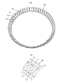
また、図1及び図2に示すように、樹脂製保持器10は、軸方向に離間した大径リング部11及び小径リング部12と、大径リング部11及び小径リング部12との間を繋ぐ、円周方向に所定の間隔で設けられた複数の柱部13と、備える。樹脂製保持器10は、射出成形で製作されており、特に、コスト面で有利なアキシャルドロー型により射出成形されることが望ましい。
As shown in FIGS. 1 and 2, the
保持器10で使用可能な樹脂組成物で用いるベース樹脂としては、一定以上の耐熱性を有する熱可塑性樹脂を使用することができる。
また、保持器10として要求される耐疲労性と、低い吸水寸法変化を満足するために、結晶性樹脂の方が好適であり、具体的には、ポリアミド46、ポリアミド66、芳香族ポリアミド樹脂、ポリフェニレンサルファイド(PPS)樹脂、ポリエーテルエーテルケトン(PEEK)樹脂等である。芳香族ポリアミド樹脂としては、ポリアミド6T/6I等の変性ポリアミド6T,ポリアミドMXD6,ポリアミド9T,ポリアミド4Tを使用することができる。以上説明したベース樹脂の中で、吸水寸法変化がほとんど無いポリフェニレンサルファイド(PPS)樹脂、ポリエーテルエーテルケトン(PEEK)樹脂が特に好適である。
As the base resin used in the resin composition that can be used in the
Further, in order to satisfy the fatigue resistance required for the
また、この樹脂組成物は、一定以上の強度を達成し、線膨張係数・吸水寸法変化を抑制するために、強化繊維材を含有する。強化繊維材としては、ガラス繊維、炭素繊維、アラミド繊維等の表面処理品(シランカップリング剤・サイジング剤で表面処理されることで、ベース樹脂との接着性向上)を好適に使用することができる。
樹脂組成物中の強化繊維材の含有量は、樹脂組成物全体の10重量%以上40重量%以下、より好ましくは15〜30重量%である。
Moreover, this resin composition contains a reinforcing fiber material in order to achieve a certain level of strength and to suppress changes in linear expansion coefficient and water absorption dimension. As the reinforcing fiber material, it is preferable to use a surface treatment product such as glass fiber, carbon fiber, and aramid fiber (adhesion with the base resin is improved by surface treatment with a silane coupling agent / sizing agent). it can.
Content of the reinforced fiber material in a resin composition is 10 to 40 weight% of the whole resin composition, More preferably, it is 15 to 30 weight%.
また、柱部13は、大径リング部寄りの部分と小径リング部寄りの部分において断面形状が異なっており、柱部13の途中で切り替わっている。即ち、図3(a)に示す柱部13の大径リング部寄りの部分は、円錐ころ4のピッチ円Cに対して内径側に円錐面14aが設けられた突出部14を有している。また、図3(b)に示す柱部13の小径リング部寄りの部分は、円錐ころ4のピッチ円Cに対して外径側に円錐面15aが設けられた突出部15を有している。
なお、円錐面14a、15aの曲率は、円錐ころ4の曲率よりも若干大きく設定されている。
Moreover, the cross-sectional shape of the
The curvatures of the
また、円錐ころ4と樹脂製保持器10とを一体にするため、柱部13の大径リング部寄りの突出部14では、ポケットの内径側開口幅W1は、ころ大径Dw1より狭く、柱部13の小径リング部寄りの突出部15では、ポケットの外径側開口幅W2は、ころ小径Dw2より狭い寸法となる。
Further, in order to integrate the tapered
表1は、柱部13の大径リング部寄りの突出部14でのかかり代(Dw1−W1)と柱部13の小径リング部寄りの突出部15でのかかり代(Dw2−W2)を0.1mm〜0.7mmの間で0.1mmずつ変えて、ころ挿入性及びころ保持性を試験した結果を示している。なお、その他の条件については、同一としている。また、表中、◎はころ挿入性及びころ保持性の両方が良好であることを示しており、○は、ころ挿入性及びころ保持性のいずれかが◎の場合よりも低いが実施可能ではあることを示しており、×は、ころ挿入性及びころ保持性のいずれかが実施不可能であることを示している。
Table 1 shows the amount of protrusion (Dw1-W1) at the protruding
この結果から、柱部13の大径リング部寄りの突出部14でのかかり代(Dw1−W1)を0.1mm〜0.7mmとし、柱部13の小径リング部寄りの突出部15でのかかり代(Dw2−W2)を0.1mm〜0.6mmとすることが好ましいことがわかる。特に、ころ挿入性ところ保持性との良好なバランスの観点から、柱部13の大径リング部寄りの突出部14でのかかり代(Dw1−W1)を0.2mm〜0.6mmとし、柱部13の小径リング部寄りの突出部15でのかかり代(Dw2−W2)を0.1mm〜0.3mmとすることが好ましい。
From this result, it is assumed that the allowance (Dw1-W1) at the protruding

また、図1に示すように、大径リング部11の内周面には、大径リング部11の肉厚t1が柱部13の肉厚tよりも薄くなるように環状の切欠き部16が形成され、保持器10の内周面は、柱部13から大径リング部11にかけて段付き形状に形成される。また、切欠き部16は、柱部13の一部を径方向に沿って切欠いている。これにより、大径リング部11の肉厚が薄くなるとともに、柱部13の突出部14も一部切除されるので、大径リング部側の柱部13の弾性変形量が大きくなり、保持器10の内側から円錐ころ4が挿入しやすくなる。
また、環状の切欠き部16には、内輪3の大鍔3bが入り込むことができ、その分だけ大鍔3bを大きくしてアキシャル荷重の負荷を増大することができる。さらに、切欠き部16は、柱部13の一部を径方向に沿って切欠いているので、大鍔3bとの干渉を回避することができる。
Further, as shown in FIG. 1, an annular notch is formed on the inner peripheral surface of the large-
Further, the
また、図1に示すように、円錐ころ軸受1の回転軸線に対する保持器10の外周面の傾斜角度α2は、円錐ころ軸受1の接触角αに対応して、32°30´以上55°未満、好ましくは、32°30´以上54°以下に設定される。
In addition, as shown in FIG. 1, the inclination angle α 2 of the outer peripheral surface of the
本実施形態の円錐ころ軸受1は、高モーメント剛性を得るためには、軸受配列として背面組合せ(DB組合せ)で使用することが望ましい。
また、円錐ころ軸受1は、予圧荷重を高めればモーメント剛性を向上する事が可能であるが、その反面、軸受の寿命が低下する可能性があるため、特殊熱処理(浸炭処理又は浸炭窒化処理)を施した長寿命鋼を使用することが好ましい。
In order to obtain high moment rigidity, the tapered
Further, the tapered
ここで、軸受基本動定格荷重(Cr)×20%以上〜60%以下の荷重条件下で、接触角を変えながら、モーメント剛性及び寿命について比較を行った。表2で、◎は、実施可能且つ効果が良いことを表し、○は、◎よりも性能は劣るが、実施可能であることを表し、△は、○よりも性能は劣るが、実施可能であることを表し、×は、効果が良くないことを表している。この表2の結果から、接触角を35°〜55°とすることで、高いモーメント剛性と長寿命が得られることがわかる。 Here, the bearing rigidity and life were compared while changing the contact angle under the load basic bearing load rating (Cr) × 20% to 60%. In Table 2, ◎ indicates that it is feasible and has good effects, ○ indicates that performance is inferior to ◎, but is feasible, and △ indicates performance is inferior to ○, but is feasible. X indicates that the effect is not good. From the results of Table 2, it can be seen that high moment rigidity and long life can be obtained by setting the contact angle to 35 ° to 55 °.
次に、上記試験結果が良好な実施例3〜6の内部諸元を再検討し、更にコンパクト化の観点から各諸元から受ける影響を検証した。また、表3に示している基本動定格荷重比は、比較例4の基本動定格荷重を1とする場合、比較例4と比較した値である。表3で、◎は、実施可能且つ効果が良いことを表し、○は、◎よりも性能は劣るが、実施可能であることを表し、×は、効果が良くないことを表している。この表3の結果を総合的に判断すると、実施例8〜11のように、接触角が本発明の要件を満たすことで、モーメント剛性、長寿命化が図られることがわかり、また、Lw/B、Dw1/H、(D1−d)/2Hが本発明の要件を満たすことで、さらにコンパクト化や大鍔の強度向上が図られることがわかる。 Next, the internal specifications of Examples 3 to 6 with good test results were reviewed, and the influence received from each specification was further verified from the viewpoint of compactness. The basic dynamic load rating ratio shown in Table 3 is a value compared with Comparative Example 4 when the basic dynamic load rating of Comparative Example 4 is 1. In Table 3, “◎” indicates that it is feasible and effective, “◯” indicates that the performance is inferior to “◎”, but “×” indicates that the effect is not good. Comprehensively determining the results in Table 3, it can be seen that, as in Examples 8 to 11, when the contact angle satisfies the requirements of the present invention, moment rigidity and long life can be achieved. It can be seen that B, Dw1 / H, and (D1-d) / 2H satisfy the requirements of the present invention, so that further downsizing and improvement of the strength of the ridge are achieved.
また、予圧比が4における従来品(比較例4)の円錐ころ軸受におけるモーメント剛性及び寿命を1としたときの、発明品(実施例8)の各予圧比におけるモーメント剛性比及び寿命比を表4及び図4に示す。なお、予圧比とは、一定値の予圧を「1」と設定したときに、この「1」に対して比で表わされる値である。また、予圧比「0」と示すのは、0「N」のことである。 The moment stiffness ratio and life ratio of each preload ratio of the invention product (Example 8) when the moment stiffness and life of the conventional product (Comparative Example 4) tapered roller bearing with a preload ratio of 4 are set as 1. 4 and FIG. The preload ratio is a value expressed as a ratio with respect to “1” when a predetermined value of preload is set to “1”. Also, the preload ratio “0” indicates 0 “N”.
図4に示すように、発明品(実施例8)の円錐ころ軸受は、予圧比4のとき、従来品(比較例4)に対するモーメント剛性比が2.1、また、比較例4に対する寿命比が4となっている。また、いずれの予圧比においても、発明品(実施例8)の円錐ころ軸受は、モーメント剛性比及び寿命比において、従来品(比較例4)よりも高い値を示していることがわかる。 As shown in FIG. 4, the inventive tapered roller bearing (Example 8) has a moment rigidity ratio of 2.1 with respect to the conventional product (Comparative Example 4) and a life ratio with respect to Comparative Example 4 when the preload ratio is 4. Is 4. It can also be seen that the tapered roller bearing of the invention (Example 8) shows a higher value than the conventional product (Comparative Example 4) in the moment rigidity ratio and life ratio at any preload ratio.
以上説明したように、本実施形態の円錐ころ軸受1によれば、内輪3の大径側端部には大鍔3bが形成され、且つ、内輪軌道面3aは、内輪3の小径側端面3cまで連続しており、さらに接触角αが45°に設定されている。これにより、モーメント剛性を向上することができ、また、ころ長さを長くして負荷容量を大きくとることができ、高モーメント剛性及び長寿命化を図ることができる。
また、接触角αは、35°〜55°の範囲とすることでモーメント剛性を向上することができ、軸受間距離が短い場合、具体的には、軸受間距離が軸受の組立幅Tの4倍以下の場合に、接触角αを35°〜55°の範囲とすると、軸受のモーメント剛性を向上する上で特に有効である。
As described above, according to the tapered
The moment rigidity can be improved by setting the contact angle α to a range of 35 ° to 55 °. When the distance between the bearings is short, specifically, the distance between the bearings is 4 of the assembly width T of the bearing. If the contact angle α is in the range of 35 ° to 55 ° in the case of the double or less, it is particularly effective in improving the moment rigidity of the bearing.
また、円錐ころ軸受1の内径をd、内輪外径をD1としたとき、内輪大鍔側高さ(D1-d)/2と径方向断面肉厚Hの比が0.7<(D1-d)/2H<0.9に設定されるので、大鍔をバックアップすることができ、大鍔3bの強度を大幅に向上することができる。
Further, when the inner diameter of the tapered
さらに、ころ長さLwと内輪幅Bの比が0.8<Lw/B<1.2に設定されるので、コンパクト化が図られ、負荷容量を大きくすることができ、高モーメント剛性、長寿命化を図ることができる。 Furthermore, since the ratio of the roller length Lw to the inner ring width B is set to 0.8 <Lw / B <1.2, the size can be reduced, the load capacity can be increased, the high moment rigidity, Life can be extended.
また、径方向断面肉厚Hと内径dの比が0.05<H/d<0.15に設定されるので、径方向に薄肉で、コンパクトな構成とすることができる。 Further, since the ratio of the radial cross-sectional thickness H to the inner diameter d is set to 0.05 <H / d <0.15, the structure can be made thin in the radial direction and compact.
加えて、円錐ころのころ大径Dw1と径方向断面肉厚Hの比が0.3<Dw1/H<0.6であることで、コンパクト化が図られ、負荷容量を大きくすることができ、高モーメント剛性、長寿命化を図ることができる。 In addition, since the ratio of the tapered roller large diameter Dw1 to the radial cross-sectional thickness H is 0.3 <Dw1 / H <0.6, it is possible to reduce the size and increase the load capacity. High moment rigidity and long life can be achieved.
また、大径リング部11の内周面には、大径リング部11の肉厚t1が柱部13の肉厚tよりも薄くなるように環状の切欠き部16が形成される。これにより、保持器10の柱部13の弾性変形量が大きくなり、保持器10の内側から円錐ころ4を挿入しやすくすることができる。
An
さらに、柱部13は、大径リング部寄りの突出部14において、0.1mm〜0.7mmのかかり代とし、ポケットPの内径側開口幅W1が円錐ころ4のころ大径Dw1より狭くなるように形成され、且つ、小径リング部寄りの突出部15において、0.1mm〜0.6mmのかかり代とし、ポケットPの外径側開口幅W2が円錐ころ4のころ小径Dw2より狭くなるように形成される。これにより、保持器10への円錐ころ4の挿入性及び保持性を向上することができる。
なお、本発明の保持器10は、アキシャルドロー型での射出成形に限定されるものでなく、即ち、柱部13は、ポケットPの内径側の少なくとも一部において、0.1mm〜0.7mmのかかり代とし、ポケットPの内径側開口幅W1が円錐ころ4のころ大径Dw1より狭くなるように形成され、且つ、ポケットPの外径側の少なくとも一部において、0.1mm〜0.6mmのかかり代とし、ポケットPの外径側開口幅W2が円錐ころ4のころ小径Dw2より狭くなるように形成されればよい。
Further, the
Note that the
また、保持器10の傾斜角度α2は、32°30´以上55°未満に設定されるので、保持器10は、接触角αが35°〜55°の急勾配の円錐ころ軸受1にも適用することができる。
The inclination angle alpha 2 of the
また、本実施形態の円錐ころ軸受1は、高モーメント剛性及び長寿命を実現するために内輪小鍔をなくし、その分のころ長さを長くしている。これに対応する為に本実施形態は、保持器10のかかり代を設定することで、保持器10のころ保持性能を向上させ、円錐ころ3と保持器10の一体化を実現している。よって、本実施形態の円錐ころ軸受1に採用される保持器10は、本来ころを保持する機能を果たす内輪小鍔の代わりにその役割を担うことを実現しており、接触角が35°〜55°の急勾配円錐ころ軸受のころ落下を有効的に抑制することができる。
Further, the tapered
なお、本発明は、上述した実施形態に限定されるものでなく、適宜、変形、改良などが可能である。
例えば、上記実施形態では、大径リング部11の内周面に環状の切欠き部16が形成されているが、本発明は、大径リング部11の内周面と、小径リング部12の外周面との少なくとも一方に、環状の切欠き部が形成されればよい。例えば、図5に示す変形例のように、大径リング部11の内周面と小径リング部12の外周面との両方に、両リング部11、12の肉厚t1、t2が柱部13の肉厚tよりも薄くなるように環状の切欠き部16、17を形成し、保持器10の両側から円錐ころ4を挿入しやすくしてもよい。
In addition, this invention is not limited to embodiment mentioned above, A deformation | transformation, improvement, etc. are possible suitably.
For example, in the above-described embodiment, the
また、本発明の円錐ころ軸受は、産業ロボット、搬送装置、モータ用等の各種の減速機に適用可能であり、具体的な適用例について以下に示す。 Further, the tapered roller bearing of the present invention can be applied to various reduction gears for industrial robots, conveyance devices, motors, and the like, and specific application examples are shown below.
(適用例1)
図6は、本発明の円錐ころ軸受が適用される直交軸歯車減速機の縦断面図である。この直交軸歯車減速機は、モータと組合せて物流機器等に用いる歯車減速機に組み込まれ、L側(入力側より見て減速機左側面)と、R側の両方に軸出しをするものであり、図6は、L軸出しの例である。
(Application example 1)
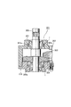
FIG. 6 is a longitudinal sectional view of an orthogonal shaft gear reducer to which the tapered roller bearing of the present invention is applied. This orthogonal shaft gear reducer is incorporated into a gear reducer used in logistics equipment in combination with a motor, and is aligned to both the L side (the left side of the reducer as viewed from the input side) and the R side. FIG. 6 is an example of L-axis alignment.
図6中、201は減速用の歯車を収める歯車箱である。202はL側軸出しされた中実出力軸、203は中空出力軸である。図6の場合は上半分が中実出力軸202を使用した場合、下半分が中空出力軸203を使用した場合を示している。歯車箱201は中心線cに対して左右対称に構成され、形状、寸法も全く同一である。左右の出力軸軸出部は出力軸カバー206又は207を歯車箱201にボルト締めにより固定している。なお軸出し側の出力軸カバー206のみ軸出し用穴を加工してある。
In FIG. 6,
図6において、中実出力軸202は歯車箱201に嵌装された、本発明の円錐ころ軸受1で両側を支持され、中間の最大直径部202aを挟んでその両側に出力ギヤ204を嵌合する出力ギヤ嵌合部202cが対をなして設けられている。また、図6の下半分に示した中空出力軸203の場合も含め、円錐ころ軸受の嵌合部202dの直径は中実出力軸202と同一にしている。
In FIG. 6, the
そして、図示しないベベルピニオンと噛合するベベルギヤ210を支持する軸211には、ピニオン212が設けられる。出力ギヤ204はピニオン212と噛合し、ベベルギヤ210に伝達された動力が、出力軸202、203へと伝達される。
A
(適用例2)
図7は、本発明の円錐ころ軸受が適用されるハイポイド式の減速機付き電動機の減速機部の拡大側断面図である。
(Application example 2)
FIG. 7 is an enlarged side sectional view of a reduction gear portion of a hypoid type motor with a reduction gear to which the tapered roller bearing of the present invention is applied.
図7において、減速機301は、電動機のベアリングブラケット302のフランジ面302aに取り付けられている。また、減速機301の内部には、電動機から延出したピニオン303と噛合されるハイポイドギヤ304と、このハイポイドギヤ304の中央部を貫いて取り付けられたスピンドル305と、このスピンドル305を回転自在に支持する2個の円錐ころ軸受1と、これら円錐ころ軸受1を収納する収納部307a、308aを備えた2ピースからなるケーシング307、308とで構成されている。
In FIG. 7, the
なお、適用例1や適用例2に使用される円錐ころ軸受1は、外輪外径を650mm以下、内輪内径を500mm以下としている。
いずれの適用例においても、本発明の円錐ころ軸受1を使用することで、コンパクトな設計でありながら、出力軸202,203、及びスピンドル305に作用するアキシャル荷重及びラジアル荷重を支承することができる。
また、図6及び図7に示すように、本発明の円錐ころ軸受1を背面組合せで取り付けることにより、モーメント剛性を向上することができる。
また、高モーメント剛性を得るためには、玉軸受よりもころ軸受を適用する方が有利であり、特に円錐ころ軸受は、ころ転動面の延長線と外内輪軌道面の延長線が、回転軸上の1ヶ所で交わる構造であるため、ころ転動面と外内輪軌道面間の滑りが発生し難く、円筒ころ軸受を適用する場合に比べて高い信頼性を得ることができる。
The tapered
In any application example, by using the tapered
Moreover, as shown in FIG.6 and FIG.7, moment rigidity can be improved by attaching the tapered
In order to obtain high moment rigidity, it is more advantageous to use roller bearings than ball bearings. In particular, tapered roller bearings have an extended line of roller rolling surfaces and an extended line of outer and inner ring raceway surfaces. Since the structure intersects at one place on the shaft, slippage between the roller rolling surface and the outer and inner ring raceway surface hardly occurs, and high reliability can be obtained as compared with the case where a cylindrical roller bearing is applied.
1 円錐ころ軸受
2 外輪
2a 外輪軌道面
3 内輪
3a 内輪軌道面
3b 大鍔
4 円錐ころ
10 円錐ころ軸受用樹脂製保持器
11 大径リング部
12 小径リング部
13 柱部
14、15 突出部
14a、15a 円錐面
B 内輪幅
D 外径
D1 内輪外径
Dw1 ころ大径
H 径方向断面肉厚
d 内径
Lw ころ長さ
T 組立幅
α 接触角
α2 保持器傾斜角度
C 円錐ころのピッチ円
P ポケット
DESCRIPTION OF
Claims (28)
前記内輪の大径側端部には大鍔が形成され、且つ、前記内輪軌道面は、前記内輪の小径側端面まで連続しており、
接触角αが45°であり、
前記円錐ころのころ大径Dw1と径方向断面肉厚Hの比が0.3<Dw1/H<0.6であることを特徴とする円錐ころ軸受。 An outer ring having an outer ring raceway surface on an inner peripheral surface, an inner ring having an inner ring raceway surface on an outer peripheral surface, and a plurality of tapered rollers arranged to be freely rollable between the outer ring raceway surface and the inner ring raceway surface; A tapered roller bearing comprising:
A large collar is formed at the large diameter side end of the inner ring, and the inner ring raceway surface continues to the small diameter side end surface of the inner ring,
Contact angle α is Ri 45 ° der,
The tapered roller bearing characterized in that a ratio of the roller large diameter Dw1 of the tapered roller to the radial cross-sectional thickness H is 0.3 <Dw1 / H <0.6 .
前記内輪の大径側端部には大鍔が形成され、且つ、前記内輪軌道面は、前記内輪の小径側端面まで連続しており、
接触角αが35°〜55°であり、
前記円錐ころのころ大径Dw1と径方向断面肉厚Hの比が0.3<Dw1/H<0.6であることを特徴とする円錐ころ軸受。 An outer ring having an outer ring raceway surface on an inner peripheral surface, an inner ring having an inner ring raceway surface on an outer peripheral surface, and a plurality of tapered rollers arranged to be freely rollable between the outer ring raceway surface and the inner ring raceway surface; A tapered roller bearing comprising:
A large collar is formed at the large diameter side end of the inner ring, and the inner ring raceway surface continues to the small diameter side end surface of the inner ring,
The contact angle α is 35 ° to 55 °,
The tapered roller bearing characterized in that a ratio of the roller large diameter Dw1 of the tapered roller to the radial cross-sectional thickness H is 0.3 <Dw1 / H <0.6 .
前記内輪は、大径側端部と小径側端部のうち、該大径側端部のみに大鍔が形成され、
接触角αが35°〜55°であり、
前記円錐ころのころ大径Dw1と径方向断面肉厚Hの比が0.3<Dw1/H<0.6であることを特徴とする円錐ころ軸受。 An outer ring having an outer ring raceway surface on an inner peripheral surface, an inner ring having an inner ring raceway surface on an outer peripheral surface, and a plurality of tapered rollers arranged to be freely rollable between the outer ring raceway surface and the inner ring raceway surface; A tapered roller bearing comprising:
The inner ring has a large collar formed only at the large-diameter side end of the large-diameter side end and the small-diameter side end,
The contact angle α is 35 ° to 55 °,
The tapered roller bearing characterized in that a ratio of the roller large diameter Dw1 of the tapered roller to the radial cross-sectional thickness H is 0.3 <Dw1 / H <0.6 .
前記柱部は、前記ポケットの内径側の少なくとも一部において、0.1mm〜0.7mmのかかり代とし、前記ポケットの内径側開口幅が前記円錐ころのころ大径より狭くなるように形成され、且つ、The column portion is formed with a margin of 0.1 mm to 0.7 mm in at least a part of the inner diameter side of the pocket, and the inner diameter side opening width of the pocket is narrower than the large diameter of the tapered roller. ,and,
前記ポケットの外径側の少なくとも一部において、0.1mm〜0.6mmのかかり代とし、前記ポケットの外径側開口幅が前記円錐ころのころ小径より狭くなるように形成されることを特徴とする請求項1〜6のいずれか1項に記載の円錐ころ軸受。At least a part of the outer diameter side of the pocket has a margin of 0.1 mm to 0.6 mm, and the opening diameter of the outer diameter side of the pocket is narrower than the small diameter of the tapered roller. The tapered roller bearing according to any one of claims 1 to 6.
前記環状の切欠き部には、前記大鍔が入り込んでいることを特徴とする請求項9に記載の円錐ころ軸受。 The annular notch is formed on the inner peripheral surface of the large-diameter ring portion,
The tapered roller bearing according to claim 9 , wherein the large collar is inserted into the annular notch.
前記内輪の大径側端部には大鍔が形成され、且つ、前記内輪軌道面は、前記内輪の小径側端面まで連続しており、A large collar is formed at the large diameter side end of the inner ring, and the inner ring raceway surface continues to the small diameter side end surface of the inner ring,
接触角αが45°であり、The contact angle α is 45 °,
ころ長さLwと内輪幅Bの比が0.8<Lw/B<1.2であることを特徴とする円錐ころ軸受。A tapered roller bearing characterized in that the ratio of the roller length Lw to the inner ring width B is 0.8 <Lw / B <1.2.
前記内輪の大径側端部には大鍔が形成され、且つ、前記内輪軌道面は、前記内輪の小径側端面まで連続しており、A large collar is formed at the large diameter side end of the inner ring, and the inner ring raceway surface continues to the small diameter side end surface of the inner ring,
接触角αが35°〜55°であり、 The contact angle α is 35 ° to 55 °,
ころ長さLwと内輪幅Bの比が0.8<Lw/B<1.2であることを特徴とする円錐ころ軸受。 A tapered roller bearing characterized in that the ratio of the roller length Lw to the inner ring width B is 0.8 <Lw / B <1.2.
前記内輪は、大径側端部と小径側端部のうち、該大径側端部のみに大鍔が形成され、The inner ring has a large collar formed only at the large-diameter side end of the large-diameter side end and the small-diameter side end,
接触角αが35°〜55°であり、The contact angle α is 35 ° to 55 °,
ころ長さLwと内輪幅Bの比が0.8<Lw/B<1.2であることを特徴とする円錐ころ軸受。A tapered roller bearing characterized in that the ratio of the roller length Lw to the inner ring width B is 0.8 <Lw / B <1.2.
前記柱部は、前記ポケットの内径側の少なくとも一部において、0.1mm〜0.7mmのかかり代とし、前記ポケットの内径側開口幅が前記円錐ころのころ大径より狭くなるように形成され、且つ、The column portion is formed with a margin of 0.1 mm to 0.7 mm in at least a part of the inner diameter side of the pocket, and the inner diameter side opening width of the pocket is narrower than the large diameter of the tapered roller. ,and,
前記ポケットの外径側の少なくとも一部において、0.1mm〜0.6mmのかかり代とし、前記ポケットの外径側開口幅が前記円錐ころのころ小径より狭くなるように形成されることを特徴とする請求項11〜15のいずれか1項に記載の円錐ころ軸受。At least a part of the outer diameter side of the pocket has a margin of 0.1 mm to 0.6 mm, and the opening diameter of the outer diameter side of the pocket is narrower than the small diameter of the tapered roller. The tapered roller bearing according to any one of claims 11 to 15.
前記内輪の大径側端部には大鍔が形成され、且つ、前記内輪軌道面は、前記内輪の小径側端面まで連続しており、A large collar is formed at the large diameter side end of the inner ring, and the inner ring raceway surface continues to the small diameter side end surface of the inner ring,
接触角αが45°であり、The contact angle α is 45 °,
径方向断面肉厚Hと内径dの比が0.05<H/d<0.15であることを特徴とする円錐ころ軸受。 A tapered roller bearing characterized in that the ratio of the radial sectional wall thickness H to the inner diameter d is 0.05 <H / d <0.15.
前記内輪の大径側端部には大鍔が形成され、且つ、前記内輪軌道面は、前記内輪の小径側端面まで連続しており、A large collar is formed at the large diameter side end of the inner ring, and the inner ring raceway surface continues to the small diameter side end surface of the inner ring,
接触角αが35°〜55°であり、The contact angle α is 35 ° to 55 °,
径方向断面肉厚Hと内径dの比が0.05<H/d<0.15であることを特徴とする円錐ころ軸受。 A tapered roller bearing characterized in that the ratio of the radial sectional wall thickness H to the inner diameter d is 0.05 <H / d <0.15.
前記内輪は、大径側端部と小径側端部のうち、該大径側端部のみに大鍔が形成され、The inner ring has a large collar formed only at the large-diameter side end of the large-diameter side end and the small-diameter side end,
接触角αが35°〜55°であり、The contact angle α is 35 ° to 55 °,
径方向断面肉厚Hと内径dの比が0.05<H/d<0.15であることを特徴とする円錐ころ軸受。 A tapered roller bearing characterized in that the ratio of the radial sectional wall thickness H to the inner diameter d is 0.05 <H / d <0.15.
前記柱部は、前記ポケットの内径側の少なくとも一部において、0.1mm〜0.7mmのかかり代とし、前記ポケットの内径側開口幅が前記円錐ころのころ大径より狭くなるように形成され、且つ、The column portion is formed with a margin of 0.1 mm to 0.7 mm in at least a part of the inner diameter side of the pocket, and the inner diameter side opening width of the pocket is narrower than the large diameter of the tapered roller. ,and,
前記ポケットの外径側の少なくとも一部において、0.1mm〜0.6mmのかかり代とし、前記ポケットの外径側開口幅が前記円錐ころのころ小径より狭くなるように形成されることを特徴とする請求項17〜20のいずれか1項に記載の円錐ころ軸受。At least a part of the outer diameter side of the pocket has a margin of 0.1 mm to 0.6 mm, and the opening diameter of the outer diameter side of the pocket is narrower than the small diameter of the tapered roller. The tapered roller bearing according to any one of claims 17 to 20.
前記内輪の大径側端部には大鍔が形成され、且つ、前記内輪軌道面は、前記内輪の小径側端面まで連続しており、A large collar is formed at the large diameter side end of the inner ring, and the inner ring raceway surface continues to the small diameter side end surface of the inner ring,
接触角αが45°であり、The contact angle α is 45 °,
前記円錐ころ軸受の内径をd、内輪外径をD1としたとき、内輪大鍔側高さ(D1-d)/2と径方向断面肉厚Hの比が0.7<(D1-d)/2H<0.9であることを特徴とする円錐ころ軸受。When the inner diameter of the tapered roller bearing is d and the outer diameter of the inner ring is D1, the ratio of the inner ring large collar side height (D1-d) / 2 to the radial cross-sectional thickness H is 0.7 <(D1-d). /2H<0.9, a tapered roller bearing.
前記内輪の大径側端部には大鍔が形成され、且つ、前記内輪軌道面は、前記内輪の小径側端面まで連続しており、A large collar is formed at the large diameter side end of the inner ring, and the inner ring raceway surface continues to the small diameter side end surface of the inner ring,
接触角αが35°〜55°であり、The contact angle α is 35 ° to 55 °,
前記円錐ころ軸受の内径をd、内輪外径をD1としたとき、内輪大鍔側高さ(D1-d)/2と径方向断面肉厚Hの比が0.7<(D1-d)/2H<0.9であることを特徴とする円錐ころ軸受。When the inner diameter of the tapered roller bearing is d and the outer diameter of the inner ring is D1, the ratio of the inner ring large collar side height (D1-d) / 2 to the radial cross-sectional thickness H is 0.7 <(D1-d). /2H<0.9, a tapered roller bearing.
前記内輪は、大径側端部と小径側端部のうち、該大径側端部のみに大鍔が形成され、The inner ring has a large collar formed only at the large-diameter side end of the large-diameter side end and the small-diameter side end,
接触角αが35°〜55°であり、The contact angle α is 35 ° to 55 °,
前記円錐ころ軸受の内径をd、内輪外径をD1としたとき、内輪大鍔側高さ(D1-d)/2と径方向断面肉厚Hの比が0.7<(D1-d)/2H<0.9であることを特徴とする円錐ころ軸受。When the inner diameter of the tapered roller bearing is d and the outer diameter of the inner ring is D1, the ratio of the inner ring large collar side height (D1-d) / 2 to the radial cross-sectional thickness H is 0.7 <(D1-d). /2H<0.9, a tapered roller bearing.
前記柱部は、前記ポケットの内径側の少なくとも一部において、0.1mm〜0.7mmのかかり代とし、前記ポケットの内径側開口幅が前記円錐ころのころ大径より狭くなるように形成され、且つ、The column portion is formed with a margin of 0.1 mm to 0.7 mm in at least a part of the inner diameter side of the pocket, and the inner diameter side opening width of the pocket is narrower than the large diameter of the tapered roller. ,and,
前記ポケットの外径側の少なくとも一部において、0.1mm〜0.6mmのかかり代とし、前記ポケットの外径側開口幅が前記円錐ころのころ小径より狭くなるように形成されることを特徴とする請求項22〜24のいずれか1項に記載の円錐ころ軸受。At least a part of the outer diameter side of the pocket has a margin of 0.1 mm to 0.6 mm, and the opening diameter of the outer diameter side of the pocket is narrower than the small diameter of the tapered roller. The tapered roller bearing according to any one of claims 22 to 24.
前記内輪の大径側端部には大鍔が形成され、且つ、前記内輪軌道面は、前記内輪の小径側端面まで連続しており、A large collar is formed at the large diameter side end of the inner ring, and the inner ring raceway surface continues to the small diameter side end surface of the inner ring,
接触角αが45°であり、The contact angle α is 45 °,
軸方向に離間した大径リング部及び小径リング部と、該大径リング部及び小径リング部との間を繋ぐ複数の柱部と、を有し、前記複数の円錐ころを収容保持する複数のポケットを画成する樹脂製保持器をさらに備え、A plurality of small diameter ring portions and a large diameter ring portion spaced apart in the axial direction; and a plurality of column portions connecting between the large diameter ring portion and the small diameter ring portion; It further includes a resin cage that defines the pocket,
前記柱部は、前記ポケットの内径側の少なくとも一部において、0.1mm〜0.7mmのかかり代とし、前記ポケットの内径側開口幅が前記円錐ころのころ大径より狭くなるように形成され、且つ、The column portion is formed with a margin of 0.1 mm to 0.7 mm in at least a part of the inner diameter side of the pocket, and the inner diameter side opening width of the pocket is narrower than the large diameter of the tapered roller. ,and,
前記ポケットの外径側の少なくとも一部において、0.1mm〜0.6mmのかかり代とし、前記ポケットの外径側開口幅が前記円錐ころのころ小径より狭くなるように形成されることを特徴とする円錐ころ軸受。At least a part of the outer diameter side of the pocket has a margin of 0.1 mm to 0.6 mm, and the opening diameter of the outer diameter side of the pocket is narrower than the small diameter of the tapered roller. Tapered roller bearing.
前記内輪の大径側端部には大鍔が形成され、且つ、前記内輪軌道面は、前記内輪の小径側端面まで連続しており、A large collar is formed at the large diameter side end of the inner ring, and the inner ring raceway surface continues to the small diameter side end surface of the inner ring,
接触角αが35°〜55°であり、The contact angle α is 35 ° to 55 °,
軸方向に離間した大径リング部及び小径リング部と、該大径リング部及び小径リング部との間を繋ぐ複数の柱部と、を有し、前記複数の円錐ころを収容保持する複数のポケットを画成する樹脂製保持器をさらに備え、A plurality of small diameter ring portions and a large diameter ring portion spaced apart in the axial direction; and a plurality of column portions connecting between the large diameter ring portion and the small diameter ring portion; It further includes a resin cage that defines the pocket,
前記柱部は、前記ポケットの内径側の少なくとも一部において、0.1mm〜0.7mmのかかり代とし、前記ポケットの内径側開口幅が前記円錐ころのころ大径より狭くなるように形成され、且つ、The column portion is formed with a margin of 0.1 mm to 0.7 mm in at least a part of the inner diameter side of the pocket, and the inner diameter side opening width of the pocket is narrower than the large diameter of the tapered roller. ,and,
前記ポケットの外径側の少なくとも一部において、0.1mm〜0.6mmのかかり代とし、前記ポケットの外径側開口幅が前記円錐ころのころ小径より狭くなるように形成されることを特徴とする円錐ころ軸受。At least a part of the outer diameter side of the pocket has a margin of 0.1 mm to 0.6 mm, and the opening diameter of the outer diameter side of the pocket is narrower than the small diameter of the tapered roller. Tapered roller bearing.
前記内輪は、大径側端部と小径側端部のうち、該大径側端部のみに大鍔が形成され、The inner ring has a large collar formed only at the large-diameter side end of the large-diameter side end and the small-diameter side end,
接触角αが35°〜55°であり、The contact angle α is 35 ° to 55 °,
軸方向に離間した大径リング部及び小径リング部と、該大径リング部及び小径リング部との間を繋ぐ複数の柱部と、を有し、前記複数の円錐ころを収容保持する複数のポケットを画成する樹脂製保持器をさらに備え、A plurality of small diameter ring portions and a large diameter ring portion spaced apart in the axial direction; and a plurality of column portions connecting between the large diameter ring portion and the small diameter ring portion; It further includes a resin cage that defines the pocket,
前記柱部は、前記ポケットの内径側の少なくとも一部において、0.1mm〜0.7mmのかかり代とし、前記ポケットの内径側開口幅が前記円錐ころのころ大径より狭くなるように形成され、且つ、The column portion is formed with a margin of 0.1 mm to 0.7 mm in at least a part of the inner diameter side of the pocket, and the inner diameter side opening width of the pocket is narrower than the large diameter of the tapered roller. ,and,
前記ポケットの外径側の少なくとも一部において、0.1mm〜0.6mmのかかり代とし、前記ポケットの外径側開口幅が前記円錐ころのころ小径より狭くなるように形成されることを特徴とする円錐ころ軸受。At least a part of the outer diameter side of the pocket has a margin of 0.1 mm to 0.6 mm, and the opening diameter of the outer diameter side of the pocket is narrower than the small diameter of the tapered roller. Tapered roller bearing.
Priority Applications (1)
| Application Number | Priority Date | Filing Date | Title |
|---|---|---|---|
| JP2013267846A JP6065826B2 (en) | 2012-12-25 | 2013-12-25 | Tapered roller bearings |
Applications Claiming Priority (5)
| Application Number | Priority Date | Filing Date | Title |
|---|---|---|---|
| JP2012280994 | 2012-12-25 | ||
| JP2012280994 | 2012-12-25 | ||
| JP2013241278 | 2013-11-21 | ||
| JP2013241278 | 2013-11-21 | ||
| JP2013267846A JP6065826B2 (en) | 2012-12-25 | 2013-12-25 | Tapered roller bearings |
Publications (3)
| Publication Number | Publication Date |
|---|---|
| JP2015121311A JP2015121311A (en) | 2015-07-02 |
| JP2015121311A5 JP2015121311A5 (en) | 2016-06-16 |
| JP6065826B2 true JP6065826B2 (en) | 2017-01-25 |
Family
ID=53533087
Family Applications (1)
| Application Number | Title | Priority Date | Filing Date |
|---|---|---|---|
| JP2013267846A Active JP6065826B2 (en) | 2012-12-25 | 2013-12-25 | Tapered roller bearings |
Country Status (1)
| Country | Link |
|---|---|
| JP (1) | JP6065826B2 (en) |
Family Cites Families (5)
| Publication number | Priority date | Publication date | Assignee | Title |
|---|---|---|---|---|
| JPS58165324U (en) * | 1982-04-30 | 1983-11-04 | 光洋精工株式会社 | tapered roller bearing |
| JP2007024110A (en) * | 2005-07-13 | 2007-02-01 | Ntn Corp | Tapered roller bearing and retainer for tapered roller bearing |
| JP2008180246A (en) * | 2007-01-23 | 2008-08-07 | Ntn Corp | Tapered roller bearing |
| JP2010025155A (en) * | 2008-07-15 | 2010-02-04 | Nsk Ltd | Conical roller bearing for wheel |
| JP5807384B2 (en) * | 2011-05-24 | 2015-11-10 | 株式会社ジェイテクト | Tapered roller bearing |
-
2013
- 2013-12-25 JP JP2013267846A patent/JP6065826B2/en active Active
Also Published As
| Publication number | Publication date |
|---|---|
| JP2015121311A (en) | 2015-07-02 |
Similar Documents
| Publication | Publication Date | Title |
|---|---|---|
| WO2014104132A1 (en) | Tapered roller bearing | |
| JP6388191B2 (en) | Tapered roller bearings | |
| WO2014163177A1 (en) | Tapered roller bearing-use resin made cage and tapered roller bearing provided with such cage | |
| US20150323008A1 (en) | Tapered roller bearing | |
| JP5969571B2 (en) | Electric motor that can prevent foreign matter from entering the housing | |
| WO2018092707A1 (en) | Rolling bearing cage and rolling bearing | |
| JP2015124796A (en) | Tapered roller bearing | |
| JP4661424B2 (en) | Rotation support | |
| JP6065826B2 (en) | Tapered roller bearings | |
| JP2016008641A (en) | Tapered roller bearing | |
| JP2009275719A (en) | Deep groove ball bearing | |
| JP6432178B2 (en) | Tapered roller bearings | |
| JP2008286319A (en) | Synthetic resin crown type cage for cleaner motor bearing and rolling bearing for cleaner motor | |
| JP3220447U (en) | Tapered roller bearings | |
| JP3223235U (en) | Tapered roller bearings | |
| JP2007127199A (en) | Retainer for rolling bearing and rolling bearing | |
| JP2015006850A (en) | Rack pinion-type steering gear unit | |
| JP2014228079A (en) | Rolling bearing | |
| JP6024291B2 (en) | Rolling bearing | |
| JP5703894B2 (en) | Ball bearing | |
| JP2006316820A (en) | Bearing unit with aligning function and steering column bearing device | |
| JP2004108539A (en) | Rolling bearing | |
| JP2005127459A (en) | Rolling bearing | |
| JP2006349105A (en) | Cage for rolling bearing | |
| JP2008202780A (en) | Shell-shaped needle roller bearing |
Legal Events
| Date | Code | Title | Description |
|---|---|---|---|
| A521 | Request for written amendment filed |
Free format text: JAPANESE INTERMEDIATE CODE: A523 Effective date: 20160421 |
|
| A621 | Written request for application examination |
Free format text: JAPANESE INTERMEDIATE CODE: A621 Effective date: 20160421 |
|
| A871 | Explanation of circumstances concerning accelerated examination |
Free format text: JAPANESE INTERMEDIATE CODE: A871 Effective date: 20160421 |
|
| A975 | Report on accelerated examination |
Free format text: JAPANESE INTERMEDIATE CODE: A971005 Effective date: 20160607 |
|
| A131 | Notification of reasons for refusal |
Free format text: JAPANESE INTERMEDIATE CODE: A131 Effective date: 20160628 |
|
| A521 | Request for written amendment filed |
Free format text: JAPANESE INTERMEDIATE CODE: A523 Effective date: 20160825 |
|
| TRDD | Decision of grant or rejection written | ||
| A01 | Written decision to grant a patent or to grant a registration (utility model) |
Free format text: JAPANESE INTERMEDIATE CODE: A01 Effective date: 20161129 |
|
| A61 | First payment of annual fees (during grant procedure) |
Free format text: JAPANESE INTERMEDIATE CODE: A61 Effective date: 20161212 |
|
| R150 | Certificate of patent or registration of utility model |
Ref document number: 6065826 Country of ref document: JP Free format text: JAPANESE INTERMEDIATE CODE: R150 |
|
| R157 | Certificate of patent or utility model (correction) |
Free format text: JAPANESE INTERMEDIATE CODE: R157 |
|
| S111 | Request for change of ownership or part of ownership |
Free format text: JAPANESE INTERMEDIATE CODE: R313114 |
|
| R350 | Written notification of registration of transfer |
Free format text: JAPANESE INTERMEDIATE CODE: R350 |
|
| R250 | Receipt of annual fees |
Free format text: JAPANESE INTERMEDIATE CODE: R250 |
|
| R250 | Receipt of annual fees |
Free format text: JAPANESE INTERMEDIATE CODE: R250 |
|
| R250 | Receipt of annual fees |
Free format text: JAPANESE INTERMEDIATE CODE: R250 |
|
| R250 | Receipt of annual fees |
Free format text: JAPANESE INTERMEDIATE CODE: R250 |