JP6065770B2 - Cover state determination device, cover state determination method, cover state determination system, and program - Google Patents
Cover state determination device, cover state determination method, cover state determination system, and program Download PDFInfo
- Publication number
- JP6065770B2 JP6065770B2 JP2013139574A JP2013139574A JP6065770B2 JP 6065770 B2 JP6065770 B2 JP 6065770B2 JP 2013139574 A JP2013139574 A JP 2013139574A JP 2013139574 A JP2013139574 A JP 2013139574A JP 6065770 B2 JP6065770 B2 JP 6065770B2
- Authority
- JP
- Japan
- Prior art keywords
- absorbance
- covering
- carbonaceous material
- state determination
- covering state
- Prior art date
- Legal status (The legal status is an assumption and is not a legal conclusion. Google has not performed a legal analysis and makes no representation as to the accuracy of the status listed.)
- Active
Links
Images


Description
本発明は、被覆状態判定装置、被覆状態判定方法、被覆状態判定システム及びプログラムに関する。 The present invention relates to a covering state determination device, a covering state determination method, a covering state determination system, and a program.
高炉には、鉄鉱石原料を焼き固めた焼結鉱が供給される。焼結鉱を製造する工程では、鉄鉱石原料に混ぜた炭材を燃焼させるが、この際、排ガス中に窒素酸化物(NOx)が発生する。このNOxは、炭材中に含まれる窒素が酸化したものであり、燃焼温度が低いほど発生量が多くなることが知られている。従って、NOxの発生を抑制するためには、炭材を極力高温で燃焼させることが求められる。 The blast furnace is supplied with sintered ore made from iron ore raw material. In the process of manufacturing the sintered ore, the carbon material mixed with the iron ore raw material is burned. At this time, nitrogen oxides (NOx) are generated in the exhaust gas. This NOx is obtained by oxidizing nitrogen contained in the carbonaceous material, and it is known that the generation amount increases as the combustion temperature decreases. Therefore, in order to suppress the generation of NOx, it is required to burn the carbonaceous material at a high temperature as much as possible.
そこで、下記の特許文献1では、炭材の燃焼温度を高めるために、事前に炭材粒子の表面に対し高温で溶融する被覆層を設ける技術が提案されている。かかる特許文献1では、炭材及び消石灰粉末に水を添加して造粒し、炭材表面に所定の厚みの消石灰被覆を付着させる方法が開示されている。また、下記の特許文献2では、炭材の表面に石灰を被覆する炭材改質処理設備が開示されている。
Therefore, in
これらの技術は、当社独自のNOx低減技術であり、経済的にNOxの低減を実現させることが期待されるため、工業的価値が極めて高いものである。 These technologies are NOx reduction technologies unique to our company, and are expected to realize NOx reduction economically, and therefore have extremely high industrial value.
ここで、上記特許文献1及び特許文献2に開示されているような改質炭材を製造する際には、適切な水分量を添加しつつ、炭材と消石灰とを混練・造粒することが求められる。ただ、水分が適正であっても、均一な厚みの消石灰被覆を実現するまでには、ある程度の混練時間を要する。この混練時間は、混練機の構造、転動回数等といった混練の状況(混練条件)に応じて異なるものとなる。
Here, when producing modified carbon materials such as those disclosed in
上記特許文献1に開示された技術では、十分に混練して均一な厚みの消石灰被覆が生成されていることを前提としている。しかしながら、もし混煉が不足していれば被覆が不均一になり、この結果、炭材燃料の着火温度を高めることによる排ガス中のNOxの低減効果が得られないことが懸念される。従って、上記特許文献2に開示されているような設備を用いて表層被覆炭材を連続的に製造する場合、何らかの手段で表層被覆の状態をモニタリングすることが望まれる。
The technique disclosed in
表層被覆炭材の表面被覆状態を判定する場合、一般的には、製造ラインにて製造された成形物をサンプルとし、製造ラインから取得したサンプルをオフラインで測定することで判定がなされることが多い。しかしながら、製造された成形物をサンプリングし、オフラインで判定を行う方法では、分析に時間を要するため、製造制御へのフィードバックが遅くなるという問題がある。 When determining the surface coating state of the surface layer coated carbon material, in general, the molded product manufactured in the production line is used as a sample, and the determination can be made by measuring the sample acquired from the production line offline. Many. However, in the method of sampling the manufactured molded product and performing the determination offline, there is a problem in that feedback to manufacturing control is delayed because analysis takes time.
このように、表層被覆炭材の表面被覆状態をより短時間で判定可能な方法が希求されていた。 Thus, there has been a demand for a method that can determine the surface coating state of the surface-coated carbonaceous material in a shorter time.
そこで、本発明は、上記問題に鑑みてなされたものであり、本発明の目的とするところは、表層被覆炭材の被覆状態をより短時間で判定することが可能な、被覆状態判定装置、被覆状態判定方法、被覆状態判定システム及びプログラムを提供することにある。 Then, this invention is made | formed in view of the said problem, The place made into the objective of this invention is the coating state determination apparatus which can determine the coating state of surface layer coating | coating carbon material in a shorter time, The object is to provide a covering state determination method, a covering state determination system, and a program.
上記課題を解決するために、本発明のある観点によれば、所定量の水分を含有した消石灰及び炭材を混練することで製造される、前記炭材の表面に前記消石灰が被覆された表層被覆炭材について、赤外光を利用した赤外線水分計による前記表層被覆炭材の吸光度の測定結果を示した測定データに基づいて、前記表層被覆炭材の被覆状態を判定する被覆状態判定部を備える被覆状態判定装置が提供される。 In order to solve the above problems, according to one aspect of the present invention, a surface layer in which the surface of the carbonaceous material is coated with the slaked lime, which is produced by kneading slaked lime containing a predetermined amount of water and the carbonaceous material. About the coated carbon material, based on the measurement data showing the measurement result of the absorbance of the surface layer coated carbon material by an infrared moisture meter using infrared light, a coating state determination unit for determining the coating state of the surface layer coated carbon material A covering state determination apparatus is provided.
前記被覆状態判定部は、予め取得した、前記消石灰及び前記炭材が完全に混練された状態における前記吸光度と、前記測定データにおける前記吸光度と、の差に基づいて前記被覆状態を数値化し、得られた数値に基づき前記表層被覆炭材の被覆状態を判定してもよい。 The covering state determination unit quantifies the covering state based on a difference between the absorbance obtained in advance and the absorbance in a state where the slaked lime and the carbonaceous material are completely kneaded and the absorbance in the measurement data. You may determine the coating | coated state of the said surface layer covering carbon material based on the obtained numerical value.
前記被覆状態判定部は、前記消石灰及び前記炭材が完全に分離して存在する状態における前記吸光度を予め取得しておき、前記完全に混練された状態における吸光度と、前記完全に分離して存在する状態における吸光度と、で規定される吸光度の範囲内での前記測定データにおける吸光度が該当する位置に応じて、前記被覆状態を数値化してもよい。 The covering state determination unit acquires the absorbance in a state where the slaked lime and the carbonaceous material are completely separated and existed in advance, and the absorbance in the completely kneaded state and the completely separated exist. The covering state may be quantified in accordance with the position where the absorbance in the measurement data falls within the range of absorbance defined by
前記完全に分離して存在する状態における吸光度は、当該状態に対応する試料を予め測定することで取得されたものであってもよい。 The absorbance in the state of being completely separated may be obtained by measuring in advance a sample corresponding to the state.
前記完全に分離して存在する状態における吸光度は、前記所定量の水分を含有した前記消石灰及び前記炭材のそれぞれを単独で測定した測定結果に基づいて算出されたものであってもよい。 The absorbance in the state of being completely separated may be calculated based on a measurement result obtained by measuring each of the slaked lime and the carbonaceous material containing the predetermined amount of water.
また、上記課題を解決するために、本発明の別の観点によれば、所定量の水分を含有した消石灰及び炭材を混練することで製造される、前記炭材の表面に前記消石灰が被覆された表層被覆炭材について、赤外光を利用した赤外線水分計による前記表層被覆炭材の吸光度の測定結果を示した測定データに基づいて、前記表層被覆炭材の被覆状態を判定する被覆状態判定ステップを含む被覆状態判定方法が提供される。 Moreover, in order to solve the said subject, according to another viewpoint of this invention, the said slaked lime coat | covers the surface of the said carbonaceous material manufactured by knead | mixing the slaked lime and carbonaceous material containing predetermined amount of water | moisture content. About the surface layer coated carbon material, the coating state for judging the coating state of the surface layer coated carbon material based on the measurement data showing the measurement result of the absorbance of the surface layer coated carbon material by the infrared moisture meter using infrared light A covering state determination method including a determination step is provided.
また、上記課題を解決するために、本発明の更に別の観点によれば、所定量の水分を含有した消石灰及び炭材を混練することで製造される、前記炭材の表面に前記消石灰が被覆された表層被覆炭材の被覆状態を判定するシステムであって、前記表層被覆炭材を所定の波長帯域の赤外光を利用して測定し、前記表層被覆炭材の吸光度の測定結果を示した測定データを生成する赤外線水分計と、前記赤外線水分計により生成された前記測定データに基づいて、前記表層被覆炭材の被覆状態を判定する被覆状態判定部を有する被覆状態判定装置と、を備える被覆状態判定システムが提供される。 Moreover, in order to solve the said subject, according to another viewpoint of this invention, the said slaked lime is manufactured on the surface of the said carbonaceous material manufactured by knead | mixing the slaked lime and carbonaceous material containing predetermined amount of water | moisture content. A system for determining a coating state of a coated surface layer carbonaceous material, wherein the surface layer coated carbon material is measured using infrared light in a predetermined wavelength band, and a measurement result of the absorbance of the surface layer coated carbon material is obtained. An infrared moisture meter that generates the indicated measurement data, and a coating state determination device that includes a coating state determination unit that determines a coating state of the surface layer coated carbonaceous material based on the measurement data generated by the infrared moisture meter; A covering state determination system is provided.
また、上記課題を解決するために、本発明の更に別の観点によれば、コンピュータに、所定量の水分を含有した消石灰及び炭材を混練することで製造される、前記炭材の表面に前記消石灰が被覆された表層被覆炭材について、赤外光を利用した赤外線水分計による前記表層被覆炭材の吸光度の測定結果を示した測定データに基づいて、前記表層被覆炭材の被覆状態を判定する被覆状態判定機能を実現させるためのプログラムが提供される。 In order to solve the above problems, according to still another aspect of the present invention, the surface of the carbonaceous material is manufactured by kneading a slaked lime containing a predetermined amount of water and the carbonaceous material in a computer. For the surface layer coated carbon material coated with the slaked lime, based on the measurement data showing the measurement result of the absorbance of the surface layer coated carbon material by an infrared moisture meter using infrared light, the covering state of the surface layer coated carbon material is A program for realizing a covering state determination function for determination is provided.
以上説明したように本発明によれば、表層被覆炭材の赤外線帯域での吸光度に着目することにより、表層被覆炭材の表面被覆状態をより短時間で判定することが可能となる。 As described above, according to the present invention, it is possible to determine the surface covering state of the surface-coated carbonaceous material in a shorter time by paying attention to the absorbance in the infrared band of the surface-coated carbonaceous material.
以下に添付図面を参照しながら、本発明の好適な実施の形態について詳細に説明する。なお、本明細書及び図面において、実質的に同一の機能構成を有する構成要素については、同一の符号を付することにより重複説明を省略する。 Exemplary embodiments of the present invention will be described below in detail with reference to the accompanying drawings. In addition, in this specification and drawing, about the component which has the substantially same function structure, duplication description is abbreviate | omitted by attaching | subjecting the same code | symbol.
(被覆状態判定システムの全体構成について)
まず、図1〜図3を参照しながら、本発明の実施形態に係る被覆状態判定システムの全体構成について、簡単に説明する。
(About the overall configuration of the covering state determination system)
First, an overall configuration of a covering state determination system according to an embodiment of the present invention will be briefly described with reference to FIGS.
なお、以下では、製造ラインで製造される成形物である表層被覆炭材の一例として、粉状コークス(以下、単に「粉コークス」とも称する。)と、消石灰とを混練して粉コークスの表面に消石灰を被覆することで製造される改質コークスを挙げて説明を行うものとする。しかしながら、本発明の実施形態に係る被覆状態判定システムにおける判定対象物である表層被覆炭材は、この改質コークスに限定されるわけではない。 In the following, as an example of the surface-coated carbon material that is a molded product manufactured on the production line, powdered coke (hereinafter, also simply referred to as “powder coke”) and slaked lime are kneaded and the surface of the powdered coke. The modified coke produced by coating slaked lime with a modified coke will be described. However, the surface coating carbonaceous material that is the determination target in the coating state determination system according to the embodiment of the present invention is not limited to this modified coke.
図1は、改質コークスの製造ラインと、この製造ラインに設けられる本発明の実施形態に係る被覆状態判定システムの全体構成と、を模式的に示した説明図であり、図2は、赤外線水分計の原理を説明するための模式図である。 FIG. 1 is an explanatory diagram schematically showing a modified coke production line and an overall configuration of a coating state determination system according to an embodiment of the present invention provided in the production line. FIG. It is a schematic diagram for demonstrating the principle of a moisture meter.
本発明の実施形態で着目する改質コークスは、例えば粒径が1〜2mm程度の粉コークスと、粉コークスよりも粒径の小さな(例えば、70μm程度以下)消石灰を用いて製造され、図1に示したように、粉コークスの粒子表面に消石灰からなる被膜が形成されたものである。 The modified coke to which attention is paid in the embodiment of the present invention is manufactured using, for example, powder coke having a particle size of about 1 to 2 mm and slaked lime having a particle size smaller than that of the powder coke (for example, about 70 μm or less). As shown in Fig. 2, a coating film made of slaked lime is formed on the surface of the powder coke particles.
このような改質コークスは、図1に例示したように、消石灰槽1に貯蔵された消石灰(Ca(OH)2)と、コークス槽2に貯蔵された粉コークスと、を用いて製造される。
Such modified coke is produced using slaked lime (Ca (OH) 2 ) stored in the
コークス槽2に貯蔵されている粉コークスは、搬送コンベア3により混練装置4まで搬送されるが、この搬送の際に、搬送コンベア3の上方に設けられた水分計5により、粉コークスの水分量が予め測定される。また、この搬送コンベア3上で、消石灰槽1から切出された消石灰が、所定の配合割合(例えば、全体質量に対して12.8質量%程度)となるように粉コークス上に積層される。
The powder coke stored in the
混練装置4では、粉コークス及び消石灰に対して操業上の目標となる水分値(例えば14%程度)となるまで水が供給されたうえで、混練処理が行われ、粉コークスの表面に消石灰からなる被膜がコーティングされた改質コークスの成形物が製造される。
In the
改質コークスの成形物は、搬送コンベア7により成品槽8へと搬送される途中で、赤外線水分計9により所定の赤外波長帯域での吸光度が測定された後、成品槽8に貯蔵される。なお、赤外線水分計9は、搬送コンベア7を搬送される改質コークスの吸光度を、例えば、常時、連続的に測定する。
The molded product of the modified coke is stored in the
ここで、混練装置4において供給された水の量や、水分計5による粉コークスの水分量の測定結果や、赤外線水分計9による吸光度の測定データは、例えば1又は複数の操業データ保持サーバ20へと逐次出力されて、保管される。
Here, the amount of water supplied in the
本発明の実施形態に係る被覆状態判定装置10は、操業データ保持サーバ20に保持されている吸光度の測定データ等を利用して、改質コークスの表面被覆状態を判定する。この被覆状態判定装置10については、以下で改めて詳述する。
The covering
なお、図1では、被覆状態判定装置10は、操業データ保持サーバ20から各種の情報を取得するように図示しているが、被覆状態判定装置10は、操業データ保持サーバ20を介さずに、赤外線水分計9等の各種の測定機器から直接各種のデータを取得してもよい。
In FIG. 1, the covering
図2は、測定対象物の水分量を測定するために用いられる、一般的な赤外線水分計の構成を模式的に示したものであり、図3は、赤外線水分計の原理を説明するための模式図である。 FIG. 2 schematically shows the configuration of a general infrared moisture meter used for measuring the moisture content of a measurement object. FIG. 3 is a diagram for explaining the principle of the infrared moisture meter. It is a schematic diagram.
水分量を測定するための赤外線水分計は、図2に模式的に示したように、赤外線帯域の光(赤外光)を射出する赤外光源と、赤外光源から射出された赤外光を測定対象物まで導光する光学系と、波長選択フィルタと、反射赤外光をディテクタへと導光する光学系と、反射赤外光を検出するディテクタと、を主に有する。 As shown schematically in FIG. 2, an infrared moisture meter for measuring the amount of moisture includes an infrared light source that emits light in the infrared band (infrared light), and infrared light emitted from the infrared light source. Mainly to an object to be measured, a wavelength selection filter, an optical system that guides the reflected infrared light to the detector, and a detector that detects the reflected infrared light.
赤外光源から射出された赤外光は、波長選択フィルタにより測定対象物へと照射される赤外光の波長が選択されたうえで、測定対象物の測定エリア(例えば、50mmφ程度の大きさ)へと照射される。測定対象物から反射された反射赤外光は、ミラーにより集光されて、ディテクタへと導光される。 The infrared light emitted from the infrared light source is selected for the wavelength of the infrared light applied to the measurement object by the wavelength selection filter, and then the measurement area of the measurement object (for example, a size of about 50 mmφ). ). The reflected infrared light reflected from the measurement object is collected by the mirror and guided to the detector.
赤外線水分計では、水による吸収のある波長(λw)での反射赤外光の強度(分光反射光強度)と、波長λwの近傍に位置する、水による吸収のない波長(λb1,λb2)での反射赤外光の強度(分光反射光強度)と、をそれぞれ測定する。このような波長は、水の吸収波長に基づいて適宜決定することが可能であるが、例えば、波長λb1,λw,λb2として、それぞれ、1780nm,1940nm,2100nmを選択することが可能である。その後、赤外線水分計は、ディテクタによるこれらの測定結果に基づいて、測定対象物の吸光度を算出する。 The infrared moisture meter, the intensity of the reflected infrared light in the wavelength of absorption by water (lambda w) and (spectral reflection light intensity), located in the vicinity of the wavelength lambda w, no water absorption wavelength (lambda b1, The intensity of reflected infrared light (spectral reflected light intensity) at λ b2 ) is measured. Such a wavelength can be appropriately determined based on the absorption wavelength of water. For example, 1780 nm, 1940 nm, and 2100 nm can be selected as the wavelengths λ b1 , λ w , and λ b2 , respectively. is there. Thereafter, the infrared moisture meter calculates the absorbance of the measurement object based on these measurement results by the detector.
ここで、測定対象物からの反射光の絶対光量は、光源強度や対象物表面の黒さ又は散乱性などに依存するため、赤外線水分計では、例えば図3に示したように、水分吸収のない参照波長(λb1,λb2)の分光反射光強度(R(λb1),R(λb2))を基準とする。すなわち、赤外線水分計では、水分がゼロであれば分光反射光強度R(λb1),R(λw),R(λb2)が直線状になると仮定してベース直線を定める。ここで、波長λwにおけるベース直線上の分光反射強度(計算値)を、R(λw0)とする。実測される分光反射強度R(λw)は、水分量に応じて低下する。ここで、R(λw)は、ランベルト・ベールの法則に基づき、対象の水分量に対して指数関数的に変化する。かかる赤外線水分計において、吸光度は、下記(式1)に示すように、分光反射光強度R(λw0)とR(λw)との比の対数として定義される。 Here, since the absolute light quantity of the reflected light from the measurement object depends on the light source intensity, the blackness of the object surface, the scattering property, etc., in the infrared moisture meter, for example, as shown in FIG. Spectral reflected light intensity (R (λ b1 ), R (λ b2 )) of a reference wavelength (λ b1 , λ b2 ) that is not present is used as a reference. That is, in the infrared moisture meter, the base straight line is determined on the assumption that the spectral reflected light intensity R (λ b1 ), R (λ w ), R (λ b2 ) is linear when the moisture is zero. Here, the spectral reflection intensity (calculated value) on the base straight line at the wavelength λ w is R (λ w0 ). The actually measured spectral reflection intensity R (λ w ) decreases according to the amount of water. Here, R (λ w ) varies exponentially with respect to the water content of interest based on Lambert-Beer's law. In such an infrared moisture meter, the absorbance is defined as the logarithm of the ratio between the spectral reflected light intensity R (λ w0 ) and R (λ w ), as shown below (Formula 1).
一般的な赤外線水分計では、物質毎に異なる水分と吸光度との関係(検量線)を予め求めておき、上記のようにして算出した測定対象物の吸光度に基づき検量線を参照することで測定対象物の水分量を特定し、水分量の測定結果として出力する。本発明の実施形態では、赤外線水分計により算出された上記の吸光度に関するデータ(以下、単に測定データともいう。)そのものを利用して、測定対象物である表層被覆炭材の表面被覆状態を判定する。 In a general infrared moisture meter, the relationship (calibration curve) between moisture and absorbance that differs for each substance is obtained in advance, and the measurement is performed by referring to the calibration curve based on the absorbance of the measurement object calculated as described above. The moisture content of the object is specified and output as a moisture content measurement result. In the embodiment of the present invention, the surface covering state of the surface-covered carbonaceous material, which is the object to be measured, is determined using the above-described data relating to the absorbance calculated by the infrared moisture meter (hereinafter also simply referred to as measurement data). To do.
なお、本発明の実施形態では、図2及び図3に示したような、赤外線水分計で予め設定された3種類の波長における吸光度の測定結果を利用する場合について説明しているが、本発明の実施形態で着目する3種類の波長は、市販の赤外線水分計で設定されている波長に限定されるものではない。 In the embodiment of the present invention, the case where the measurement results of absorbance at three types of wavelengths preset by the infrared moisture meter as shown in FIGS. 2 and 3 are used is described. The three types of wavelengths of interest in the embodiment are not limited to the wavelengths set by commercially available infrared moisture meters.
以下で詳細に説明する本発明の実施形態に係る被覆状態判定装置10は、このような赤外線水分計から出力された吸光度の測定データに基づいて処理を行うことで、製造ライン上を搬送される改質コークスの表面被覆状態を、オンラインで短時間に測定することができる。
The covering
(表層被覆炭材の赤外線帯域における吸光度の挙動について)
以下では、まず、本発明の実施形態に係る被覆状態判定処理について説明するに先立ち、本発明者らが見出し、かつ、本実施形態に係る被覆状態判定処理で着目する知見について説明する。
(Absorbance behavior in the infrared band of surface-coated carbonaceous materials)
Hereinafter, prior to describing the covering state determination process according to the embodiment of the present invention, the knowledge found by the present inventors and focused on in the covering state determination process according to the present embodiment will be described.
本発明者らは、まず、実験室において、実機を用いた操業と同一の試料条件(消石灰の配合割合及び水分量に関する条件)を選択し、混練時間を変えながら、表層被覆炭材を製造し、拡大鏡下における表面被覆状態の違いを観察した。ここで、試料条件は、上記特許文献1にも記載されているように許容範囲があり、かかる許容範囲内であれば消石灰による被覆の効果が得られるものであるが、以下の検討では、試料条件として、消石灰配合割合を12.8質量%とし、水分量を14%とした。
First, in the laboratory, the inventors select the same sample conditions (conditions relating to the blending ratio of slaked lime and moisture content) as the operation using the actual machine, and manufacture the surface-coated carbon material while changing the kneading time. The difference in the surface coating state under the magnifier was observed. Here, the sample condition has an allowable range as described in
ここで、実験室での混練処理では、混練装置として小型ミキサを使用した。実際の操業で用いられる表層被覆炭材と同様な被覆状態となってNOx低減効果が良好となる表層被覆炭材を得るために要した混練時間は、4分であった。 Here, in the kneading process in the laboratory, a small mixer was used as a kneading apparatus. The kneading time required to obtain a surface-coated carbon material having the same covering state as that of the surface-coated carbon material used in actual operation and having a good NOx reduction effect was 4 minutes.
そこで、本発明者らは、4分間混練した試料、混練時間を半分にして2分間とした試料、及び、混練時間を1/10にして0.4分間にした試料の3種類を用意した。水分14%の湿った状態では炭材と消石灰の色合いが判別しづらいため、混練後に試料を乾燥させて、拡大鏡で観察した。 Therefore, the present inventors prepared three types: a sample kneaded for 4 minutes, a sample obtained by halving the kneading time to 2 minutes, and a sample obtained by reducing the kneading time to 1/10 to 0.4 minutes. Since it was difficult to discriminate the color of the carbonaceous material and slaked lime when the moisture was 14%, the sample was dried after kneading and observed with a magnifier.
実際の操業への使用にも耐えるほど十分に混練されている試料(すなわち、混練時間4分の試料)は、拡大鏡下では、全体的にほぼ斑の無い被覆が実現されていることが確認された。一方、混練時間2分の試料は、視野中の所々に、消石灰がまとまった白い点が存在していた。また、混練時間0.4分間の試料では、視野中に、消石灰のみが造粒している白い部分と、消石灰被覆が無いため炭材がむき出しになっている黒い領域とが存在した。このように、混練が不足すると均一な被覆が実現できないことが確認された。 It is confirmed that a sample that is sufficiently kneaded to withstand use in actual operation (that is, a sample with a kneading time of 4 minutes) is almost entirely free of coating under a magnifying glass. It was done. On the other hand, the sample with a kneading time of 2 minutes had white spots with slaked lime in various places in the field of view. In addition, in the sample with a kneading time of 0.4 minutes, a white portion where only slaked lime was granulated and a black region where charcoal material was exposed because there was no slaked lime coating existed in the visual field. Thus, it was confirmed that uniform coating cannot be realized if kneading is insufficient.
次に、本発明者らは、被覆の状態が異なれば表層の保水状態が変化し、赤外線水分計の出力に変化が現れるのではないかと考え、上記の混練時間の異なる表層被覆炭材試料を、図2に示したような赤外線水分計で観察した。この際、上記の3種類の試料に加え、6分間混練した試料を追加し、計4種類の試料の測定を実施した。赤外線水分計の3波長の分光反射光強度の測定値は、図4に示す通りであった。 Next, the present inventors considered that the water retention state of the surface layer would change if the coating state was different, and that the change would appear in the output of the infrared moisture meter. The results were observed with an infrared moisture meter as shown in FIG. At this time, in addition to the above three types of samples, a sample kneaded for 6 minutes was added, and a total of four types of samples were measured. The measured values of the three-wavelength spectral reflected light intensity of the infrared moisture meter were as shown in FIG.
図4では、短波長側の参照波長の分光反射光強度を基準とした分光反射光強度の相対値を示している。すなわち、水による吸収の無い短波長側の波長(波長λb1)での分光反射光強度を基準にとり、水による吸収の無いもう一方の波長での分光反射光強度(波長λb2)と、水による吸収のある波長(波長λw)での赤外反射強度とを、相対的に表したものである。図4の縦軸は、相対的に表した分光反射光強度(以下、相対分光反射光強度ともいう。)であり、横軸は波長である。 FIG. 4 shows the relative value of the spectral reflected light intensity based on the spectral reflected light intensity of the reference wavelength on the short wavelength side. That is, based on the spectral reflected light intensity at the short wavelength side (wavelength λ b1 ) without absorption by water, the spectral reflected light intensity (wavelength λ b2 ) at the other wavelength without absorption by water, Infrared reflection intensity at a wavelength (wavelength λ w ) at which absorption is caused by. The vertical axis in FIG. 4 is the relative spectral reflected light intensity (hereinafter also referred to as relative spectral reflected light intensity), and the horizontal axis is the wavelength.
図4に示したグラフ図において、水分吸収帯の波長1940nmの相対分光反射光強度に着目すると、6分間と4分間の混練処理では、ほとんど差が見られなかった。一方、2分間混練したものと0.4分間混練したものでは、順に参照波長の分光反射光強度に対する落ち込みが増大した。なお、上記(式1)から算出された吸光度は、混練時間6分と混練時間0.4分とで、それぞれ0.042及び0.071程度となった。 In the graph shown in FIG. 4, paying attention to the intensity of relative spectral reflection light having a wavelength of 1940 nm in the water absorption band, there was almost no difference between the kneading treatment for 6 minutes and 4 minutes. On the other hand, in the case of kneading for 2 minutes and the case of kneading for 0.4 minutes, the drop of the reference wavelength with respect to the spectral reflected light intensity increased in order. The absorbance calculated from the above (Formula 1) was about 0.042 and 0.071, respectively, at a kneading time of 6 minutes and a kneading time of 0.4 minutes.
図4から明らかなように、混練時間が短くなると、水分吸収帯にあたる波長1940nmの分光反射光強度が低下し、あたかも水分が高くなったかのような測定値が得られることがわかる。かかる現象は、本発明者らによる検討によって、はじめて明らかになった知見である。 As can be seen from FIG. 4, when the kneading time is shortened, the intensity of spectral reflected light having a wavelength of 1940 nm corresponding to the moisture absorption band is decreased, and a measurement value as if moisture has increased can be obtained. Such a phenomenon is a finding that has been clarified for the first time by study by the present inventors.
かかる現象が生じる要因については定かではないものの、本発明者らは、かかる現象を説明しうる以下のような仮説を考えた。
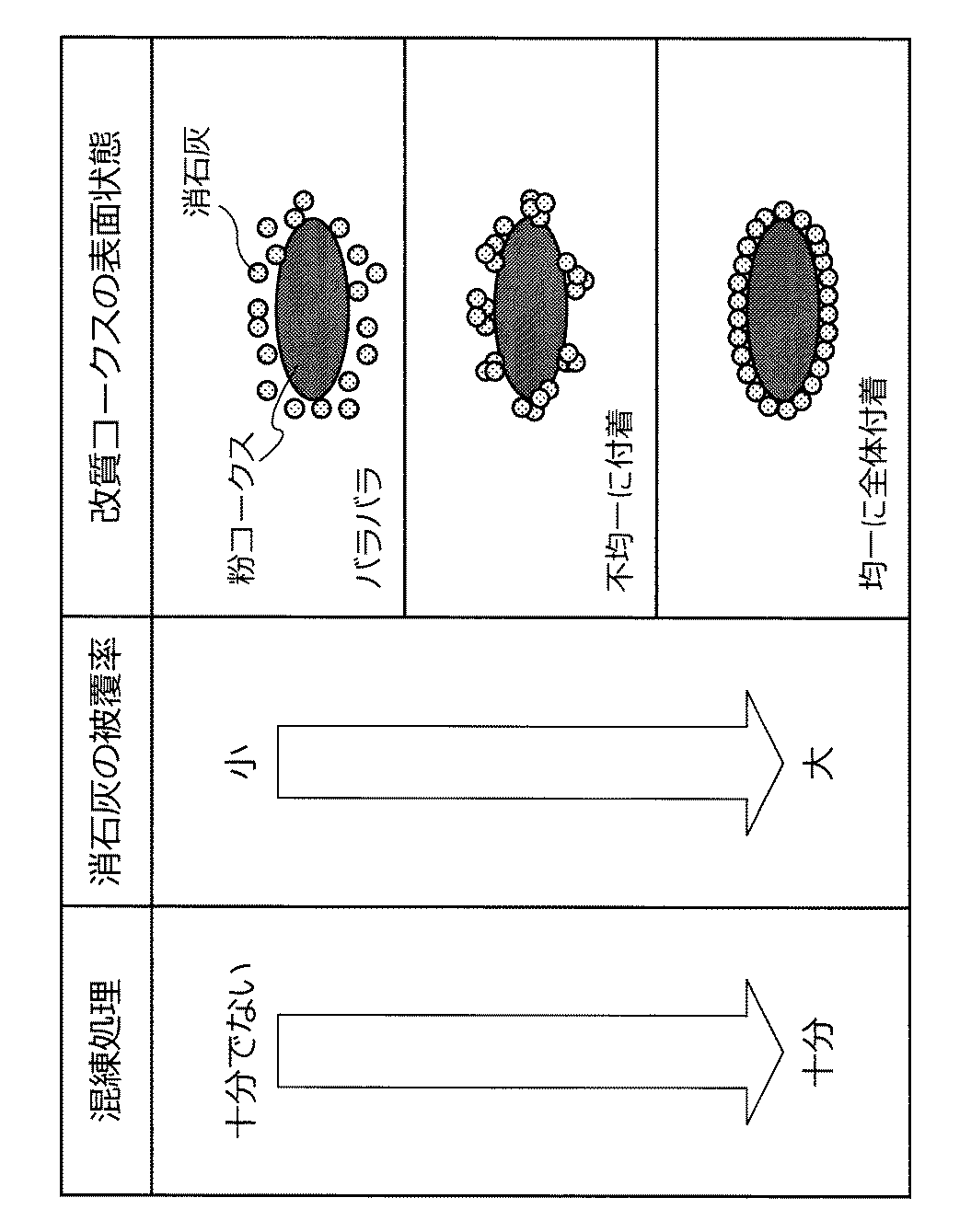
すなわち、被覆が均一であるか否かで、図5に模式的に示したように、消石灰粒子の付着の仕方に違いのある疑似粒子が存在していると考えられる。コークス等の炭材は吸水性が良く、混練に際して添加される水は容易に炭材内部へと侵入する。一方、消石灰は吸水性が悪く、表層に添加される水が留まる。ここで、炭材及び消石灰は、赤外光に対して不透明であるため、水の吸収を受ける波長の赤外線は、表層に水分が多ければ多いほど吸収量が大きくなり、反射光強度は低下していく。図5の下段に示した状態(十分に混練された状態)では、消石灰粉末の殆どが炭材に均一に接触しているため、水は吸収性の高い炭材に吸収されており、赤外線が投射される疑似粒子の表面における水分量は少なくなると考えられる。逆に、図5の中段に示した状態では、吸水性の悪い消石灰粒子同士が凝集している箇所が多く、疑似粒子全体で見れば表層の水分量が高くなる。その結果、図4に示したような現象が生じるものと考えられる。
Although the cause of the phenomenon is not clear, the present inventors have considered the following hypothesis that can explain the phenomenon.
That is, it is considered that there exist pseudo particles that differ in the manner of attachment of slaked lime particles, as schematically shown in FIG. 5, depending on whether or not the coating is uniform. Carbonaceous materials such as coke have good water absorption, and water added during kneading easily penetrates into the carbonaceous material. On the other hand, slaked lime has poor water absorption, and water added to the surface layer remains. Here, since the carbonaceous material and slaked lime are opaque to infrared light, the infrared ray having a wavelength that receives water absorption increases as the surface layer has more moisture, and the reflected light intensity decreases. To go. In the state shown in the lower part of FIG. 5 (fully kneaded state), since most of the slaked lime powder is in uniform contact with the carbonaceous material, water is absorbed by the carbonaceous material having high absorbency, and infrared rays are absorbed. It is considered that the amount of water on the surface of the projected pseudo particle is reduced. On the contrary, in the state shown in the middle part of FIG. 5, there are many places where slaked lime particles having poor water absorption are aggregated, and the moisture content of the surface layer becomes high when viewed as a whole pseudo particles. As a result, the phenomenon shown in FIG. 4 is considered to occur.
(表層被覆炭材の吸光度の挙動と表面被覆状態との関係)
次に、図6〜図8を参照しながら、表層被覆炭材の吸光度の挙動と、表面被覆状態との関係について、説明する。
上記の仮設を検証するために、本発明者らは、同一の試料条件(消石灰混合割合:12.8質量%、水分量14%)の試料を用いて、混練時間を変えた複数の試料の吸光度を、図2に示したような赤外線水分計を用いて測定した。得られた結果を図6に示した。図6において、縦軸は、(式1)により算出された吸光度であり、横軸は、混練時間である。
(Relation between absorbance behavior and surface coating state of surface coating carbonaceous material)
Next, the relationship between the absorbance behavior of the surface layer-covered carbonaceous material and the surface coating state will be described with reference to FIGS.
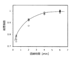
In order to verify the above-mentioned temporary setting, the present inventors used a sample having the same sample conditions (mixed slaked lime: 12.8% by mass, moisture content 14%) and used a plurality of samples with different kneading times. Absorbance was measured using an infrared moisture meter as shown in FIG. The obtained results are shown in FIG. In FIG. 6, the vertical axis represents the absorbance calculated by (Equation 1), and the horizontal axis represents the kneading time.
図6から明らかなように、混練時間が短くなれば短くなるほど測定される吸光度の値は大きくなり、混練時間が長くなれば長くなるほど、吸光度の変化量は安定して、吸光度約0.04に漸近していくことがわかる。また、拡大鏡下における表層被覆炭材の観察や図5からも明らかなように、混練時間が長くなるほど、消石灰による良好な被覆状態が実現する。従って、吸光度の漸近値は、消石灰及び炭材を完全に混練して、均一で良好な被覆状態が実現された際の吸光度と考えることができる。 As is clear from FIG. 6, the shorter the kneading time, the larger the measured absorbance value, and the longer the kneading time, the more stable the change in absorbance, and the absorbance was about 0.04. You can see that it is asymptotic. In addition, as is clear from observation of the surface layer coated carbon material under the magnifying glass and FIG. 5, the longer the kneading time is, the better the coated state with slaked lime is realized. Therefore, the asymptotic value of absorbance can be considered as the absorbance when slaked lime and carbonaceous materials are completely kneaded to achieve a uniform and good covering state.
ここで、図6は、混練条件(消石灰混合割合12.8質量%、水分量14%)における吸光度の変化の様子を示したものであるが、消石灰の混合割合や水分量を変化させた場合であっても、漸近する吸光度の値は異なるものの、測定される表層被覆炭材の吸光度の変化は、図6と同様の挙動を示した。 Here, FIG. 6 shows how the absorbance changes under the kneading conditions (slaked lime mixing ratio 12.8% by mass, moisture content 14%), but when the mixing ratio and moisture content of slaked lime are changed. Even so, although the asymptotic absorbance value is different, the measured change in the absorbance of the surface-coated carbon material showed the same behavior as in FIG.
本発明者らは、かかる知見に基づき、表層被覆炭材の吸光度を測定し、吸光度が所定の閾値以下となり安定した状態となったか否か(換言すれば、図6に示したように、測定された吸光度がある値(例えば、図6における吸光度0.04)に漸近したとみなせるか否か)に応じて、表層被覆炭材の表面被覆状態を判定できることに想到したのである。 Based on such knowledge, the inventors measured the absorbance of the surface-coated carbonaceous material and determined whether or not the absorbance became a predetermined threshold value or less (in other words, as shown in FIG. The inventors have come up with the idea that the surface covering state of the surface-covered carbonaceous material can be determined according to a certain absorbance (for example, whether or not it can be regarded as asymptotic to the absorbance 0.04 in FIG. 6).
すなわち、ある時刻に測定された表層被覆炭材の吸光度そのものに着目し、測定された吸光度が消石灰混合割合及び水分量に応じて決まる所定の閾値以下となったか否かに応じて、表層被覆炭材の表面被覆状態を判定することが可能となる。図6に示した例では、(消石灰混合割合12.8質量%、水分量14%)における吸光度の判定閾値を例えば0.043に設定し、測定された表層被覆炭材の吸光度が0.043以下か否かに応じて、良好な表面被覆状態が実現されているか否かを判定することができる。また、かかる判定方法においては、表層被覆炭材の表面被覆状態を、表層被覆炭材の吸光度で数値化しているともいえる。 That is, paying attention to the absorbance of the surface-coated carbonaceous material measured at a certain time, depending on whether the measured absorbance is below a predetermined threshold determined according to the slaked lime mixing ratio and moisture content, It becomes possible to determine the surface covering state of the material. In the example shown in FIG. 6, the determination threshold value of the absorbance in (slaked lime mixing ratio 12.8 mass%, moisture content 14%) is set to 0.043, for example, and the measured absorbance of the surface-coated carbonaceous material is 0.043. Whether or not a favorable surface covering state is realized can be determined depending on whether or not the following is true. Moreover, in this determination method, it can be said that the surface coating state of the surface-coated carbon material is quantified by the absorbance of the surface-coated carbon material.
なお、判定に用いる閾値は、例えば図6に示したように、混練時間無限遠における吸光度の漸近値としてもよいし、無限遠における漸近値に過去の操業データから得られる知見を加味し、操業上問題のない表面被覆状態(すなわち、所望の炭材燃焼温度の上昇が得られる状態)に対応する、漸近値よりも大きな値の吸光度を、判定に用いる閾値としてもよい。 Note that the threshold value used for the determination may be an asymptotic value of absorbance at the kneading time at infinity, for example, as shown in FIG. 6, or by adding knowledge obtained from past operation data to the asymptotic value at infinity. An absorbance having a value larger than an asymptotic value corresponding to a surface coating state having no problem (that is, a state in which a desired increase in the combustion temperature of the carbonaceous material can be obtained) may be used as a threshold value for determination.
本発明者らは、上記のような知見に基づき、表層被覆炭材の表面被覆状態を客観的に判定することが可能な、以下で説明する本発明の実施形態に係る被覆状態判定装置及び被覆状態判定方法に想到した。 Based on the above knowledge, the present inventors can objectively determine the surface covering state of the surface-coated carbonaceous material, and the covering state determining apparatus and covering according to the embodiment of the present invention described below I came up with a method for judging the state.
実際の操業において表層被覆炭材を製造する際には、安定して好ましい表面被覆状態が生成される混練時間を、操業上の混練時間に設定すると考えられる。ここで、上記のような知見に基づく、本発明の実施形態に係る被覆状態判定方法を利用することにより、例えば、以下のような検証を実現することが可能となる。すなわち、生産性を上げるため良好な被覆ができる限界条件を見極めたい場合や、混練装置の異常に起因する不十分な混練状態の発生を迅速に検知する場合等において、混練装置から排出される表層被覆炭材の成形物を赤外線水分計で連続的に監視し、出力される吸光度に着目することで、混練不良か否かを短時間に容易かつ客観的に判断することが可能となる。 When manufacturing the surface-coated carbonaceous material in actual operation, it is considered that the kneading time for stably producing a preferable surface coating state is set to the kneading time for operation. Here, by using the covering state determination method according to the embodiment of the present invention based on the above knowledge, for example, the following verification can be realized. In other words, the surface layer discharged from the kneading device when it is necessary to determine the limit conditions that allow good coating to increase productivity, or when the occurrence of an insufficient kneading state due to an abnormality in the kneading device is detected quickly. By continuously monitoring the molded product of the coated carbon material with an infrared moisture meter and paying attention to the output absorbance, it is possible to easily and objectively determine whether or not there is a kneading failure.
また、本発明者らは、上記の知見について更に検討を行った結果、吸光度の変化を規格化し、表層被覆炭材の表面被覆状態を0〜1の間の値で表現する被覆指数Pに想到した。かかる被覆指数Pは、より詳細には、下記の(式2)で表される値である。 Further, as a result of further examination of the above knowledge, the present inventors have come up with a coating index P that standardizes the change in absorbance and expresses the surface coating state of the surface coating carbonaceous material with a value between 0 and 1. did. More specifically, the covering index P is a value represented by the following (Formula 2).
ここで、上記(式2)において、
k:表層被覆炭材の吸光度の測定値
ki:消石灰及び炭材が完全に混練された状態における吸光度
k0:消石灰及び炭材が完全に分離して存在する状態における吸光度
であり、kiは、例えば図6における漸近値のような、完全な表面被覆状態における吸光度に対応し、k0は、消石灰の被覆が全く存在しない状態での吸光度に対応する。
Here, in the above (Formula 2),
k: Measured value of absorbance of surface-coated carbon material k i : Absorbance in a state where slaked lime and carbon material are completely kneaded k 0 : Absorbance in a state where slaked lime and carbon material are completely separated and k i Corresponds to the absorbance in the complete surface coating state, for example asymptotic values in FIG. 6, and k 0 corresponds to the absorbance in the absence of any slaked lime coating.
例えば図6において、混練時間6分における吸光度の値を、十分混練されて完全な被覆状態に相当する「被覆指数P=1」とする。かかる場合の吸光度kiを、複数の吸光度測定値の平均値として算出したところ、0.041となった。 For example, in FIG. 6, the absorbance value at a kneading time of 6 minutes is set to “coating index P = 1” corresponding to a fully coated state. The absorbance k i in this case was calculated as an average value of a plurality of absorbance measurement values, which was 0.041.
一方、被覆が全くできていない状態に相当する「被覆指数P=0」とは、炭材と消石灰とがそれぞれ単体で分離して存在する状態である。このような、被覆指数P=0に対応する吸光度k0は、例えば以下のような2つの方法の何れかにより、特定できる。 On the other hand, “covering index P = 0” corresponding to a state where the coating is not performed at all is a state where the carbonaceous material and the slaked lime are separated from each other. Such an absorbance k 0 corresponding to the coating index P = 0 can be specified by one of the following two methods, for example.
被覆指数P=0に対応する吸光度k0を特定する第1の方法は、着目している水分量(例えば、実際の操業で設定される水分量)となっている炭材及び消石灰のそれぞれ単体の吸光度を予め測定し、得られた2種類の吸光度に対して、着目している混合割合(例えば、実際の操業で設定される混合割合)と、材料固有の反射率とで重み付けした平均値を、被覆指数P=0に対応する吸光度k0とする方法である。かかる場合における吸光度k0を定式化すると、以下の(式3)のようになる。 The first method of specifying the absorbance k 0 corresponding to the covering index P = 0 is that each of the carbonaceous material and the slaked lime that has the water content of interest (for example, the water content set in actual operation). The average value weighted by the mixing ratio of interest (for example, the mixing ratio set in actual operation) and the reflectance specific to the material for the two types of absorbance obtained in advance. Is an absorbance k 0 corresponding to the coating index P = 0. When the absorbance k 0 in this case is formulated, the following (Equation 3) is obtained.
ここで、上記(式3)において、
kC:着目している水分量における炭材単独の吸光度
kL:着目している水分量における消石灰単独の吸光度
SC:炭材の混合体積割合
SL:消石灰の混合体積割合
RC:炭材の反射率
RL:消石灰の反射率
である。
Here, in the above (Formula 3),
k C: the focused absorbance k of carbonaceous material alone in water content are L: Focusing to have absorbance of slaked lime alone in water content S C: mixing volume ratio of carbonaceous material S L: mixing volume of slaked lime ratio R C: Charcoal Material reflectivity RL : The reflectivity of slaked lime.
吸光度kC及びkLを実測したところ、kC=0.021、kL=0.352であった。また、混合体積割合SC及びSLは、炭材及び消石灰の質量割合と比重とから求めればよく、SC=0.9、SL=0.1である。また、赤外線水分計が使用する波長帯域で乾燥状態(水による吸収の影響を受けない状態)での炭材及び消石灰の試料を用意し、反射率RC及びRLを測定したところ、RC=0.1、RL=0.8であった。これらの数値を上記(式3)に代入することで、被覆指数P=0に対応する吸光度k0を、0.173と求めることができる。 When the absorbance k C and k L were measured, k C = 0.021 and k L = 0.352. The mixing volume ratio S C and S L may be determined from the mass ratio and the specific gravity of the carbonaceous material and slaked lime, S C = 0.9, a S L = 0.1. Moreover, when the samples of carbonaceous materials and slaked lime in a dry state (state not affected by absorption by water) were prepared in the wavelength band used by the infrared moisture meter, and the reflectances R C and RL were measured, R C = 0.1 and R L = 0.8. By substituting these numerical values into the above (Equation 3), the absorbance k 0 corresponding to the covering index P = 0 can be obtained as 0.173.
被覆指数P=0に対応する吸光度k0を特定する第2の方法は、例えば図7に模式的に示したように、着目している質量割合の炭材及び消石灰(各原料は、着目している水分量となっている。)を分離して配置した標準試料を準備し、かかる標準試料の吸光度を実測する方法である。例えば図6に示した試料条件では、水分量14%となっている炭材を87.2質量%と、水分量14%となっている消石灰12.8質量%と、を赤外線水分計の測定視野内で分離して配置した標準試料を準備する。その上で、かかる標準試料を測定することで得られた吸光度を、被覆指数P=0に対応する吸光度k0として利用することができる。 The second method for specifying the absorbance k 0 corresponding to the covering index P = 0 is, for example, as shown schematically in FIG. This is a method in which a standard sample with separated water is prepared and the absorbance of the standard sample is measured. For example, under the sample conditions shown in FIG. 6, the carbon material having a moisture content of 14% is 87.2% by mass and the slaked lime having a moisture content of 14% is measured by 12.8% by the infrared moisture meter. Prepare a standard sample placed separately in the field of view. In addition, the absorbance obtained by measuring the standard sample can be used as the absorbance k 0 corresponding to the coating index P = 0.
図6に示した吸光度の測定データを、上記(式2)に基づいて被覆指数Pへと変換すると、図8に示したようになる。図8において、縦軸は、被覆指数Pであり、横軸は、混練時間である。 When the absorbance measurement data shown in FIG. 6 is converted into the covering index P based on the above (Equation 2), it is as shown in FIG. In FIG. 8, the vertical axis represents the coating index P, and the horizontal axis represents the kneading time.
図8に示したような被覆指数Pを利用して表層被覆炭材の表面被覆状態を判定する場合、過去の操業データ等に基づいて吸光度k0及び吸光度k1を特定し、操業上問題の無い表面被覆状態に対応する閾値を予め特定した上で、測定された吸光度から算出される被覆指数Pが、かかる閾値以上となるか否かに応じて、表面被覆状態を判定すればよい。この場合に、測定された吸光度が閾値以上である場合に、表層被覆炭材は良好な表面被覆状態となっていると判定することができる。 When determining the surface covering state of the surface layer coated carbon material using the covering index P as shown in FIG. 8, the absorbance k 0 and the absorbance k 1 are specified based on the past operation data and the like. A threshold value corresponding to an uncovered surface covering state is specified in advance, and the surface covering state may be determined according to whether or not the covering index P calculated from the measured absorbance is equal to or greater than the threshold value. In this case, when the measured absorbance is equal to or greater than the threshold value, it can be determined that the surface-coated carbonaceous material is in a good surface coating state.
前述のように、完全な被覆状態における吸光度は、水分量や消石灰の混合割合を変えることで変動すると考えられる。それ故、図6に示したように、測定された吸光度を直接利用して表面被覆状態を判定する場合には、混練不良の程度が判断しづらい場合が生じうる。一方、上記(式2)に示した被覆指数Pは、0〜1の間でスケーリングした数値を利用して、表面被覆状態の良好度合いを表しているため、被覆指数Pに着目することで、表層被覆炭材の表面被覆状態をより容易に把握することが可能となる。 As described above, the absorbance in a completely covered state is considered to vary by changing the amount of water and the mixing ratio of slaked lime. Therefore, as shown in FIG. 6, in the case of determining the surface coating state by directly using the measured absorbance, it may be difficult to determine the degree of kneading failure. On the other hand, the covering index P shown in the above (Equation 2) represents a good degree of the surface covering state by using a numerical value scaled between 0 and 1, and therefore paying attention to the covering index P, It becomes possible to grasp the surface covering state of the surface layer coated carbon material more easily.
本発明者らは、以上説明したような技術的思想に基づいて、以下で説明する被覆状態判定装置及び被覆状態判定方法に想到した。以下では、図9及び図10を参照しながら、本実施形態に係る被覆状態判定装置及び被覆状態判定方法について、詳細に説明する。 Based on the technical idea as described above, the present inventors have conceived a covering state determination apparatus and a covering state determination method described below. Hereinafter, the covering state determination device and the covering state determination method according to the present embodiment will be described in detail with reference to FIGS. 9 and 10.
(被覆状態判定装置の構成について)
まず、図9を参照しながら、本実施形態に係る被覆状態判定装置10の構成について、詳細に説明する。図9は、本実施形態に係る被覆状態判定装置10の構成の一例を示したブロック図である。
(About the configuration of the covering state determination device)
First, the configuration of the covering
本実施形態に係る被覆状態判定装置10は、赤外線水分計等の赤外線水分計により生成された、表層被覆炭材の吸光度の測定データに基づいて、表層被覆炭材の被覆状態を判定する。かかる被覆状態判定装置10は、図9に示したように、データ取得部101と、被覆状態判定部103と、結果出力部105と、表示制御部107と、記憶部109と、を主に備える。
The covering
データ取得部101は、例えば、CPU(Central Processing Unit)、ROM(Read Only Memory)、RAM(Random Access Memory)、通信装置等により実現される。データ取得部101は、例えば操業データ保持サーバ等といった、判定対象物(例えば改質コークス等といった表層被覆炭材)の赤外線帯域における吸光度の測定データを格納しているサーバやデータベース等から、測定結果を示したデータ(測定データ)を取得する。また、データ取得部101は、測定結果を示したデータを、赤外線水分計9から直接取得することも可能である。データ取得部101は、表面被覆状態の判定処理に利用する測定データを取得すると、取得した測定データを後述する被覆状態判定部103に出力する。
The
なお、データ取得部101は、必要に応じて、例えば改質コークスを製造する際に、混練装置4に供給する消石灰の含有水分、混錬装置4で添加した水の供給量等といった各種の操業データを取得して、被覆状態判定部103に出力することも可能である。
In addition, the
被覆状態判定部103は、例えば、CPU、ROM、RAM等により実現される。被覆状態判定部103は、データ取得部101が取得した吸光度の測定データに基づいて、判定対象物である表層被覆炭材(例えば、改質コークス等)の被覆状態を判定する。
The covering
より詳細には、被覆状態判定部103は、データ取得部101から出力された吸光度の測定データを利用して、後述する記憶部109等に格納されている判定閾値に基づいて、判定対象物である表層被覆炭材の表面被覆状態を判定する。
More specifically, the covering
被覆状態判定部103により実施される表層被覆炭材の表面被覆状態の判定処理は、先だって説明したような、吸光度k又は吸光度kに基づき算出される被覆指数Pを利用した判定処理である。
The determination processing of the surface covering state of the surface layer coated carbon material performed by the covering
吸光度kを利用した判定処理を行う場合には、先だって図6を参照しながら説明したように、被覆状態判定部103は、予め取得した、所定量の水分を含有する消石灰及び炭材が完全に混練された状態における吸光度(ki)と、測定データにおける吸光度kと、の差に基づいて被覆状態を数値化し、得られた数値に基づき表層被覆炭材の被覆状態を判定することとなる。
When the determination process using the absorbance k is performed, as previously described with reference to FIG. 6, the covering
また、被覆指数Pを利用した判定処理を行う場合には、先だって図8を参照しながら説明したように、被覆状態判定部103は、消石灰及び炭材が完全に分離して存在する状態における吸光度を予め取得しておいた上で、完全に混練された状態における吸光度と、完全に分離して存在する状態における吸光度と、で規定される吸光度の範囲内での測定データにおける吸光度が該当する位置に応じて被覆指数Pを算出し、かかる被覆指数Pに基づいて表層被覆炭材の被覆状態を判定することとなる。
Moreover, when performing the determination process using the covering index P, as described previously with reference to FIG. 8, the covering
なお、上記の判定処理に用いられる判定閾値は、図6や図8で示した値に限定されるものではなく、実際の操業条件に則して製造された表層被覆炭材を操業に利用する赤外線水分計9で測定することで得られた測定データを利用し、先だって説明したような方法により、操業条件に応じて事前に特定しておけばよい。
In addition, the determination threshold value used for said determination process is not limited to the value shown in FIG.6 and FIG.8, The surface layer coating | coating material manufactured according to the actual operation conditions is utilized for operation. Using the measurement data obtained by measuring with the
被覆状態判定部103は、このようにして得られた判定結果に対応するデータを、後述する結果出力部105に出力する。
The covering
結果出力部105は、例えば、CPU、ROM、RAM、出力装置、通信装置等により実現される。結果出力部105は、被覆状態判定部103から出力された判定結果に対応するデータを、被覆状態判定装置10のユーザに出力する。具体的には、結果出力部105は、判定結果に対応するデータを、当該データが生成された日時等に関する時刻データと関連づけて、各種サーバや制御装置に出力したり、プリンタ等の出力装置を利用して、紙媒体として出力したりする。また、結果出力部105は、判定結果に対応するデータを、外部に設けられたコンピュータ等の各種の情報処理装置に出力してもよいし、各種の記録媒体に出力してもよい。
The
また、結果出力部105は、判定結果に対応するデータを、被覆状態判定装置10に設けられたディスプレイ等の出力装置や、外部に設けられた各種機器の有するディスプレイ等に出力する際には、後述する表示制御部107と連携して判定結果を出力する。
In addition, when the
表示制御部107は、例えば、CPU、ROM、RAM、出力装置、通信装置等により実現される。表示制御部107は、判定結果に対応するデータをディスプレイ等の各種表示装置に表示させる際の表示制御を行う。これにより、被覆状態判定装置10のユーザは、判定対象物の表面被覆状態に関する判定結果を、その場で把握することが可能となる。
The
また、表示制御部107は、結果出力部105から出力された判定対象物の判定結果を素早く表示させる等といった表示制御を行うことができる。これにより、製造される判定対象物(例えば改質コークス等の表層被覆炭材)の表面被覆状態の判定結果が素早く表示画面に表示されることとなり、被覆状態判定装置10のユーザは、表面被覆状態が好ましくない成形物が発生したか否かの認識と、発生した異常に対する処理判断と、を素早く行うことが可能となる。また、表示制御部107は、表面被覆状態が悪化したことを通知するアラームや処置に必要な情報を表示画面上に表示させたり、警報として音声信号等を発生させたりしてもよい。
Further, the
このようにして判定結果をユーザに対して出力することで、ユーザは、表面被覆状態の悪化が発生した場合に、混練装置等の機器の点検操作や混練等の際に添加する添加水分量や混練時間等を増加させる等といった対処操作を迅速に行うことが可能となり、製品の歩留まりを向上させることが可能となる。 By outputting the determination result to the user in this way, when the deterioration of the surface coating state occurs, the user can add the amount of added water during the inspection operation or kneading of the equipment such as the kneading apparatus. Coping operations such as increasing the kneading time and the like can be performed quickly, and the yield of products can be improved.
記憶部109は、例えば、RAM、ストレージ装置等により実現される。記憶部109には、本実施形態に係る被覆状態判定装置10が、何らかの処理を行う際に保存する必要が生じた様々なパラメータや処理の途中経過等、または、各種のデータベースやプログラム等が、適宜記録される。これらのパラメータやデータベース等は、成形物の操業条件等に応じて、1又は複数格納されていてもよい。また、記憶部109には、表示制御部107が解析結果を表示させるための表示画面を構成する際に利用される、アイコン等の様々なオブジェクトが記録されていてもよい。この記憶部109は、被覆状態判定装置10が備えるデータ取得部101、演算処理部103、結果出力部105、表示制御部107等が、自由にデータのリード/ライト処理を行うことが可能である。
The
以上、本実施形態に係る被覆状態判定装置10の機能の一例を示した。上記の各構成要素は、汎用的な部材や回路を用いて構成されていてもよいし、各構成要素の機能に特化したハードウェアにより構成されていてもよい。また、各構成要素の機能を、CPU等が全て行ってもよい。従って、本実施形態を実施する時々の技術レベルに応じて、適宜、利用する構成を変更することが可能である。
Heretofore, an example of the function of the covering
なお、上述のような本実施形態に係る被覆状態判定装置の各機能を実現するためのコンピュータプログラムを作製し、パーソナルコンピュータ等に実装することが可能である。また、このようなコンピュータプログラムが格納された、コンピュータで読み取り可能な記録媒体も提供することができる。記録媒体は、例えば、磁気ディスク、光ディスク、光磁気ディスク、フラッシュメモリなどである。また、上記のコンピュータプログラムは、記録媒体を用いずに、例えばネットワークを介して配信してもよい。 A computer program for realizing each function of the covering state determination apparatus according to the present embodiment as described above can be produced and installed in a personal computer or the like. In addition, a computer-readable recording medium storing such a computer program can be provided. The recording medium is, for example, a magnetic disk, an optical disk, a magneto-optical disk, a flash memory, or the like. Further, the above computer program may be distributed via a network, for example, without using a recording medium.
(被覆状態判定方法の流れについて)
続いて、図10を参照しながら、本実施形態に係る被覆状態判定システムで実施される被覆状態判定方法の流れの一例について、簡単に説明する。図10は、本実施形態に係る被覆状態判定方法の流れの一例を示した流れ図である。
(About the flow of the covering state judgment method)
Next, an example of the flow of the covering state determination method performed by the covering state determination system according to the present embodiment will be briefly described with reference to FIG. FIG. 10 is a flowchart illustrating an example of the flow of the covering state determination method according to the present embodiment.
以下では、図10を参照しながら、吸光度k又は被覆指数Pに基づく判定処理を利用した被覆状態判定方法の流れについて、簡単に説明する。 Hereinafter, the flow of the covering state determination method using the determination process based on the absorbance k or the covering index P will be briefly described with reference to FIG.
吸光度k又は被覆指数Pに基づく判定処理を利用した被覆状態判定方法では、まず、赤外線水分計9により、判定対象物となる表層被覆炭材の一例である改質コークスの吸光度が測定される(ステップS101)。その結果、改質コークスの吸光度の測定結果を示す測定データが生成されることとなる。
In the coating state determination method using the determination process based on the absorbance k or the coating index P, first, the
被覆状態判定装置10のデータ取得部101は、赤外線水分計9により生成された改質コークスの吸光度の測定結果を示した測定データを取得して、被覆状態判定部103に出力する。被覆状態判定部103は、データ取得部101から出力された吸光度の測定データに基づいて、被覆状態を数値化する(ステップS103)。すなわち、被覆状態判定部103は、取得した測定データに記載された吸光度kそのものや、かかる吸光度kを利用して算出される被覆指数Pを利用して、改質コークスの表面被覆状態を数値化する。
The
その後、被覆状態判定部103は、記憶部109等に予め格納されている判定閾値と、吸光度k又は被覆指数Pといった表面被覆状態を数値化した値と、を利用して、改質コークスの被覆状態を判定する(ステップS105)。その後、被覆状態判定部103は、得られた判定結果を示したデータを、結果出力部105に出力する。
Thereafter, the covering
結果出力部105は、判定結果を示す情報を取得すると、取得した情報を表示制御部107及び記憶部109に出力する。表示制御部107は、これらの判定結果を示す情報を表示画面上に表示する(ステップS107)。これにより、ユーザは、製造している改質コークス等の表層被覆炭材の表面被覆状態を、短時間で把握することが可能となる。
When the
以上、図10を参照しながら、本実施形態に係る被覆状態判定方法の流れについて、簡単に説明した。 The flow of the covering state determination method according to the present embodiment has been briefly described above with reference to FIG.
(ハードウェア構成について)
次に、図11を参照しながら、本発明の実施形態に係る被覆状態判定装置10のハードウェア構成について、詳細に説明する。図11は、本発明の実施形態に係る被覆状態判定装置10のハードウェア構成を説明するためのブロック図である。
(About hardware configuration)
Next, the hardware configuration of the covering
被覆状態判定装置10は、主に、CPU901と、ROM903と、RAM905と、を備える。また、被覆状態判定装置10は、更に、バス907と、入力装置909と、出力装置911と、ストレージ装置913と、ドライブ915と、接続ポート917と、通信装置919とを備える。
The covering
CPU901は、演算処理装置および制御装置として機能し、ROM903、RAM905、ストレージ装置913、またはリムーバブル記録媒体921に記録された各種プログラムに従って、被覆状態判定装置10内の動作全般またはその一部を制御する。ROM903は、CPU901が使用するプログラムや演算パラメータ等を記憶する。RAM905は、CPU901が使用するプログラムや、プログラムの実行において適宜変化するパラメータ等を一次記憶する。これらはCPUバス等の内部バスにより構成されるバス907により相互に接続されている。
The
バス907は、ブリッジを介して、PCI(Peripheral Component Interconnect/Interface)バスなどの外部バスに接続されている。
The
入力装置909は、例えば、マウス、キーボード、タッチパネル、ボタン、スイッチおよびレバーなどユーザが操作する操作手段である。また、入力装置909は、例えば、赤外線やその他の電波を利用したリモートコントロール手段(いわゆる、リモコン)であってもよいし、被覆状態判定装置10の操作に対応したPDA等の外部接続機器923であってもよい。さらに、入力装置909は、例えば、上記の操作手段を用いてユーザにより入力された情報に基づいて入力信号を生成し、CPU901に出力する入力制御回路などから構成されている。被覆状態判定装置10のユーザは、この入力装置909を操作することにより、被覆状態判定装置10に対して各種のデータを入力したり処理動作を指示したりすることができる。
The
出力装置911は、取得した情報をユーザに対して視覚的または聴覚的に通知することが可能な装置で構成される。このような装置として、CRTディスプレイ装置、液晶ディスプレイ装置、プラズマディスプレイ装置、ELディスプレイ装置およびランプなどの表示装置や、スピーカおよびヘッドホンなどの音声出力装置や、プリンタ装置、携帯電話、ファクシミリなどがある。出力装置911は、例えば、被覆状態判定装置10が行った各種処理により得られた結果を出力する。具体的には、表示装置は、被覆状態判定装置10が行った各種処理により得られた結果を、テキストまたはイメージで表示する。他方、音声出力装置は、再生された音声データや音響データ等からなるオーディオ信号をアナログ信号に変換して出力する。
The
ストレージ装置913は、被覆状態判定装置10の記憶部の一例として構成されたデータ格納用の装置である。ストレージ装置913は、例えば、HDD(Hard Disk Drive)等の磁気記憶部デバイス、半導体記憶デバイス、光記憶デバイス、または光磁気記憶デバイス等により構成される。このストレージ装置913は、CPU901が実行するプログラムや各種データ、および外部から取得した各種のデータなどを格納する。
The
ドライブ915は、記録媒体用リーダライタであり、被覆状態判定装置10に内蔵、あるいは外付けされる。ドライブ915は、装着されている磁気ディスク、光ディスク、光磁気ディスク、または半導体メモリ等のリムーバブル記録媒体921に記録されている情報を読み出して、RAM905に出力する。また、ドライブ915は、装着されている磁気ディスク、光ディスク、光磁気ディスク、または半導体メモリ等のリムーバブル記録媒体921に記録を書き込むことも可能である。リムーバブル記録媒体921は、例えば、CDメディア、DVDメディア、Blu−ray(登録商標)メディア等である。また、リムーバブル記録媒体921は、コンパクトフラッシュ(登録商標)(CompactFlash:CF)、フラッシュメモリ、または、SDメモリカード(Secure Digital memory card)等であってもよい。また、リムーバブル記録媒体921は、例えば、非接触型ICチップを搭載したICカード(Integrated Circuit card)または電子機器等であってもよい。
The
接続ポート917は、機器を被覆状態判定装置10に直接接続するためのポートである。接続ポート917の一例として、USB(Universal Serial Bus)ポート、IEEE1394ポート、SCSI(Small Computer System Interface)ポート、RS−232Cポート等がある。この接続ポート917に外部接続機器923を接続することで、被覆状態判定装置10は、外部接続機器923から直接各種のデータを取得したり、外部接続機器923に各種のデータを提供したりする。
The
通信装置919は、例えば、通信網925に接続するための通信デバイス等で構成された通信インターフェースである。通信装置919は、例えば、有線または無線LAN(Local Area Network)、Bluetooth(登録商標)、またはWUSB(Wireless USB)用の通信カード等である。また、通信装置919は、光通信用のルータ、ADSL(Asymmetric Digital Subscriber Line)用のルータ、または、各種通信用のモデム等であってもよい。この通信装置919は、例えば、インターネットや他の通信機器との間で、例えばTCP/IP等の所定のプロトコルに則して信号等を送受信することができる。また、通信装置919に接続される通信網925は、有線または無線によって接続されたネットワーク等により構成され、例えば、インターネット、家庭内LAN、赤外線通信、ラジオ波通信または衛星通信等であってもよい。
The
以上、本発明の実施形態に係る被覆状態判定装置10の機能を実現可能なハードウェア構成の一例を示した。上記の各構成要素は、汎用的な部材を用いて構成されていてもよいし、各構成要素の機能に特化したハードウェアにより構成されていてもよい。従って、本実施形態を実施する時々の技術レベルに応じて、適宜、利用するハードウェア構成を変更することが可能である。
Heretofore, an example of the hardware configuration capable of realizing the function of the covering
(まとめ)
以上説明したように、本発明の実施形態に係る被覆状態判定装置及び被覆状態判定方法によれば、製造直後の表層被覆炭材の被覆の良・不良を、非接触かつ連続的に判定することができる。本方法を利用して被覆状態をモニタリングしつつ表層被覆炭材を製造することで、冗長な時間をかけて混練することなく、表層被覆炭材の生産性を最大限に高めることができる。例えば、本方法を利用することで、NOx低減効果が確保できる混練指数を予め把握しておき、この混練指数を下回らないように混練装置の運転条件を制御することができる。また、本方法は、ミキサやパンペレタイザーなどといった混練装置に何らかの機械的異常が発生し、十分に混練されない表層被覆炭材が製造された場合、かかる状況を迅速に検知することが可能となる。
(Summary)
As described above, according to the covering state determination device and the covering state determination method according to the embodiment of the present invention, it is possible to continuously determine whether the surface coating carbonaceous material immediately after manufacture is good or bad in the non-contact manner. Can do. By producing the surface layer coated carbon material while monitoring the coating state using this method, the productivity of the surface layer coated carbon material can be maximized without kneading over a redundant time. For example, by using this method, the kneading index that can ensure the NOx reduction effect is grasped in advance, and the operating conditions of the kneading apparatus can be controlled so as not to fall below this kneading index. In addition, according to the present method, when a mechanical abnormality occurs in a kneading apparatus such as a mixer or a pan pelletizer, and a surface-coated carbon material that is not sufficiently kneaded is produced, such a situation can be detected quickly.
以上、添付図面を参照しながら本発明の好適な実施形態について詳細に説明したが、本発明はかかる例に限定されない。本発明の属する技術の分野における通常の知識を有する者であれば、特許請求の範囲に記載された技術的思想の範疇内において、各種の変更例または修正例に想到し得ることは明らかであり、これらについても、当然に本発明の技術的範囲に属するものと了解される。 The preferred embodiments of the present invention have been described in detail above with reference to the accompanying drawings, but the present invention is not limited to such examples. It is obvious that a person having ordinary knowledge in the technical field to which the present invention pertains can come up with various changes or modifications within the scope of the technical idea described in the claims. Of course, it is understood that these also belong to the technical scope of the present invention.
10 被覆状態判定装置
101 データ取得部
103 被覆状態判定部
105 結果出力部
107 表示制御部
109 記憶部
DESCRIPTION OF
Claims (8)
ことを特徴とする、被覆状態判定装置。 The surface layer of the surface layer coated carbonaceous material produced by kneading slaked lime and carbonaceous material containing a predetermined amount of water and coated with the slaked lime on the surface of the carbonaceous material, using an infrared moisture meter using infrared light. A covering state determination device comprising: a covering state determination unit that determines a covering state of the surface layer covering carbon material based on measurement data indicating a measurement result of absorbance of the covering carbon material.
ことを特徴とする、請求項1に記載の被覆状態判定装置。 The covering state determination unit quantifies the covering state based on a difference between the absorbance obtained in advance and the absorbance in a state where the slaked lime and the carbonaceous material are completely kneaded and the absorbance in the measurement data. The covering state determining apparatus according to claim 1, wherein the covering state of the surface layer covering carbonaceous material is determined based on the obtained numerical value.
前記消石灰及び前記炭材が完全に分離して存在する状態における前記吸光度を予め取得しておき、
前記完全に混練された状態における吸光度と、前記完全に分離して存在する状態における吸光度と、で規定される吸光度の範囲内での前記測定データにおける吸光度が該当する位置に応じて、前記被覆状態を数値化する
ことを特徴とする、請求項2に記載の被覆状態判定装置。 The covering state determination unit
The absorbance in a state where the slaked lime and the carbonaceous material are completely separated and present in advance,
Depending on the position where the absorbance in the measurement data falls within the absorbance range defined by the absorbance in the completely kneaded state and the absorbance in the completely separated state, the coated state The covering state determination device according to claim 2, wherein
ことを特徴とする、請求項3に記載の被覆状態判定装置。 4. The covering state determination apparatus according to claim 3, wherein the absorbance in the state of being completely separated is obtained by measuring in advance a sample corresponding to the state.
ことを特徴とする、請求項3に記載の被覆状態判定装置。 The absorbance in the state of being completely separated is calculated based on a measurement result obtained by measuring each of the slaked lime and the carbonaceous material containing the predetermined amount of water, respectively. 3. The covering state determination apparatus according to 3.
ことを特徴とする、被覆状態判定方法。 The surface layer of the surface layer coated carbonaceous material produced by kneading slaked lime and carbonaceous material containing a predetermined amount of water and coated with the slaked lime on the surface of the carbonaceous material, using an infrared moisture meter using infrared light. A covering state determining method comprising a covering state determining step for determining a covering state of the surface layer covering carbonaceous material based on measurement data indicating a measurement result of absorbance of the covering carbonaceous material.
前記表層被覆炭材を所定の波長帯域の赤外光を利用して測定し、前記表層被覆炭材の吸光度の測定結果を示した測定データを生成する赤外線水分計と、
前記赤外線水分計により生成された前記測定データに基づいて、前記表層被覆炭材の被覆状態を判定する被覆状態判定部を有する被覆状態判定装置と、
を備える
ことを特徴とする、被覆状態判定システム。 A system for judging a covering state of a surface layer-covered carbonaceous material produced by kneading slaked lime and a carbonaceous material containing a predetermined amount of water, wherein the surface of the carbonaceous material is coated with the slaked lime,
An infrared moisture meter that measures the surface-coated carbonaceous material using infrared light in a predetermined wavelength band, and generates measurement data indicating the measurement result of the absorbance of the surface-coated carbonaceous material,
Based on the measurement data generated by the infrared moisture meter, a covering state determination device having a covering state determination unit that determines the covering state of the surface layer coated carbonaceous material,
A covering state determination system comprising:
所定量の水分を含有した消石灰及び炭材を混練することで製造される、前記炭材の表面に前記消石灰が被覆された表層被覆炭材について、赤外光を利用した赤外線水分計による前記表層被覆炭材の吸光度の測定結果を示した測定データに基づいて、前記表層被覆炭材の被覆状態を判定する被覆状態判定機能を実現させるためのプログラム。
On the computer,
The surface layer of the surface layer coated carbonaceous material produced by kneading slaked lime and carbonaceous material containing a predetermined amount of water and coated with the slaked lime on the surface of the carbonaceous material, using an infrared moisture meter using infrared light. The program for implement | achieving the covering state determination function which determines the covering state of the said surface layer covering carbon material based on the measurement data which showed the measurement result of the light absorbency of a covering carbon material.
Priority Applications (1)
| Application Number | Priority Date | Filing Date | Title |
|---|---|---|---|
| JP2013139574A JP6065770B2 (en) | 2013-07-03 | 2013-07-03 | Cover state determination device, cover state determination method, cover state determination system, and program |
Applications Claiming Priority (1)
| Application Number | Priority Date | Filing Date | Title |
|---|---|---|---|
| JP2013139574A JP6065770B2 (en) | 2013-07-03 | 2013-07-03 | Cover state determination device, cover state determination method, cover state determination system, and program |
Publications (2)
| Publication Number | Publication Date |
|---|---|
| JP2015014462A JP2015014462A (en) | 2015-01-22 |
| JP6065770B2 true JP6065770B2 (en) | 2017-01-25 |
Family
ID=52436286
Family Applications (1)
| Application Number | Title | Priority Date | Filing Date |
|---|---|---|---|
| JP2013139574A Active JP6065770B2 (en) | 2013-07-03 | 2013-07-03 | Cover state determination device, cover state determination method, cover state determination system, and program |
Country Status (1)
| Country | Link |
|---|---|
| JP (1) | JP6065770B2 (en) |
Families Citing this family (1)
| Publication number | Priority date | Publication date | Assignee | Title |
|---|---|---|---|---|
| JP7011288B2 (en) * | 2017-09-28 | 2022-01-26 | 株式会社カワタ | Mixing degree judgment method and mixing degree judgment device |
Family Cites Families (7)
| Publication number | Priority date | Publication date | Assignee | Title |
|---|---|---|---|---|
| US5338361A (en) * | 1991-11-04 | 1994-08-16 | Measurex Corporation | Multiple coat measurement and control apparatus and method |
| JP3555189B2 (en) * | 1994-08-12 | 2004-08-18 | 株式会社神戸製鋼所 | Operating method of iron ore sintering machine |
| JP2000146834A (en) * | 1998-11-05 | 2000-05-26 | Hitachi Ltd | Moisture measuring method and moisture measuring device and manufacture of electric apparatus |
| JP2006047688A (en) * | 2004-08-04 | 2006-02-16 | Ricoh Co Ltd | Electrostatic charge image developing toner and evaluation method |
| JP4890645B2 (en) * | 2008-07-07 | 2012-03-07 | 新日本製鐵株式会社 | Moisture measurement method for blended raw materials |
| JP6036517B2 (en) * | 2013-04-22 | 2016-11-30 | 新日鐵住金株式会社 | Surface state determination device, surface state determination method, surface state determination system, and program |
| JP6036516B2 (en) * | 2013-04-22 | 2016-11-30 | 新日鐵住金株式会社 | Surface state determination device, surface state determination method, surface state determination system, and program |
-
2013
- 2013-07-03 JP JP2013139574A patent/JP6065770B2/en active Active
Also Published As
| Publication number | Publication date |
|---|---|
| JP2015014462A (en) | 2015-01-22 |
Similar Documents
| Publication | Publication Date | Title |
|---|---|---|
| Hagan et al. | Assessing the accuracy of low-cost optical particle sensors using a physics-based approach | |
| JP4645422B2 (en) | Determination device, determination device control program, and recording medium recording determination device control program | |
| Li et al. | Inter-comparison of black carbon measurement methods for simulated open biomass burning emissions | |
| Dickau et al. | Methodology for quantifying the volatile mixing state of an aerosol | |
| Cho et al. | Effects of a mixture of chloromethylisothiazolinone and methylisothiazolinone on peripheral airway dysfunction in children | |
| JP2013228241A (en) | Measuring apparatus, method, program, and recording medium | |
| Pokhrel et al. | Impact of combustion conditions on physical and morphological properties of biomass burning aerosol | |
| Xu et al. | Multivariate quality control solved by one‐class partial least squares regression: identification of adulterated peanut oils by mid‐infrared spectroscopy | |
| Modini et al. | Detailed characterization of the CAPS single-scattering albedo monitor (CAPS PMssa) as a field-deployable instrument for measuring aerosol light absorption with the extinction-minus-scattering method | |
| JP6036517B2 (en) | Surface state determination device, surface state determination method, surface state determination system, and program | |
| Nakagawa et al. | Design and characterization of a novel single-particle polar nephelometer | |
| CN109637636A (en) | Data processing method and device | |
| GB2568313A (en) | Method and apparatus for determining powder condition | |
| JP6065770B2 (en) | Cover state determination device, cover state determination method, cover state determination system, and program | |
| Momose et al. | Applying terahertz technology for nondestructive detection of crack initiation in a film-coated layer on a swelling tablet | |
| Jeronimo et al. | Analysis of black carbon on filters by image-based reflectance | |
| JP6161867B2 (en) | Lubricant spreading analysis device, method, program, recording medium | |
| Stacey et al. | Raman spectroscopy and X‐ray diffraction responses when measuring health‐related micrometre and nanometre particle size fractions of crystalline quartz and the measurement of quartz in dust samples from the cutting and polishing of natural and artificial stones | |
| JP6036516B2 (en) | Surface state determination device, surface state determination method, surface state determination system, and program | |
| JP6547472B2 (en) | Shape measuring device | |
| Villa-Aleman et al. | Diffuse reflectance spectroscopy and principal component analysis to retrospectively determine production history of plutonium dioxide | |
| Stacey et al. | Multicomponent measurement of respirable quartz, kaolinite and coal dust using Fourier transform infrared spectroscopy (FTIR): a comparison between partial least squares and principal component regressions | |
| JP2012220138A (en) | Method and device for controlling air-fuel ratio of heating furnace, and program | |
| CN107153033A (en) | The method for measuring content of ashes in polymer sample | |
| Gyakwaa et al. | Quantification of Synthetic Nonmetallic Inclusion Multiphase Mixtures from a CaO–Al2O3–MgO–CaS System Using Raman Spectroscopy |
Legal Events
| Date | Code | Title | Description |
|---|---|---|---|
| A621 | Written request for application examination |
Free format text: JAPANESE INTERMEDIATE CODE: A621 Effective date: 20160303 |
|
| TRDD | Decision of grant or rejection written | ||
| A977 | Report on retrieval |
Free format text: JAPANESE INTERMEDIATE CODE: A971007 Effective date: 20161125 |
|
| A01 | Written decision to grant a patent or to grant a registration (utility model) |
Free format text: JAPANESE INTERMEDIATE CODE: A01 Effective date: 20161129 |
|
| A61 | First payment of annual fees (during grant procedure) |
Free format text: JAPANESE INTERMEDIATE CODE: A61 Effective date: 20161212 |
|
| R151 | Written notification of patent or utility model registration |
Ref document number: 6065770 Country of ref document: JP Free format text: JAPANESE INTERMEDIATE CODE: R151 |
|
| S533 | Written request for registration of change of name |
Free format text: JAPANESE INTERMEDIATE CODE: R313533 |
|
| R350 | Written notification of registration of transfer |
Free format text: JAPANESE INTERMEDIATE CODE: R350 |