JP6065537B2 - Information device and information device link mechanism - Google Patents
Information device and information device link mechanism Download PDFInfo
- Publication number
- JP6065537B2 JP6065537B2 JP2012252534A JP2012252534A JP6065537B2 JP 6065537 B2 JP6065537 B2 JP 6065537B2 JP 2012252534 A JP2012252534 A JP 2012252534A JP 2012252534 A JP2012252534 A JP 2012252534A JP 6065537 B2 JP6065537 B2 JP 6065537B2
- Authority
- JP
- Japan
- Prior art keywords
- casing
- housing
- display unit
- lock
- slide
- Prior art date
- Legal status (The legal status is an assumption and is not a legal conclusion. Google has not performed a legal analysis and makes no representation as to the accuracy of the status listed.)
- Active
Links
Images


Classifications
-
- H—ELECTRICITY
- H05—ELECTRIC TECHNIQUES NOT OTHERWISE PROVIDED FOR
- H05K—PRINTED CIRCUITS; CASINGS OR CONSTRUCTIONAL DETAILS OF ELECTRIC APPARATUS; MANUFACTURE OF ASSEMBLAGES OF ELECTRICAL COMPONENTS
- H05K5/00—Casings, cabinets or drawers for electric apparatus
- H05K5/02—Details
- H05K5/0217—Mechanical details of casings
- H05K5/0226—Hinges
-
- G—PHYSICS
- G06—COMPUTING; CALCULATING OR COUNTING
- G06F—ELECTRIC DIGITAL DATA PROCESSING
- G06F1/00—Details not covered by groups G06F3/00 - G06F13/00 and G06F21/00
- G06F1/16—Constructional details or arrangements
-
- G—PHYSICS
- G06—COMPUTING; CALCULATING OR COUNTING
- G06F—ELECTRIC DIGITAL DATA PROCESSING
- G06F1/00—Details not covered by groups G06F3/00 - G06F13/00 and G06F21/00
- G06F1/16—Constructional details or arrangements
- G06F1/1613—Constructional details or arrangements for portable computers
- G06F1/1615—Constructional details or arrangements for portable computers with several enclosures having relative motions, each enclosure supporting at least one I/O or computing function
- G06F1/1616—Constructional details or arrangements for portable computers with several enclosures having relative motions, each enclosure supporting at least one I/O or computing function with folding flat displays, e.g. laptop computers or notebooks having a clamshell configuration, with body parts pivoting to an open position around an axis parallel to the plane they define in closed position
-
- G—PHYSICS
- G06—COMPUTING; CALCULATING OR COUNTING
- G06F—ELECTRIC DIGITAL DATA PROCESSING
- G06F1/00—Details not covered by groups G06F3/00 - G06F13/00 and G06F21/00
- G06F1/16—Constructional details or arrangements
- G06F1/1613—Constructional details or arrangements for portable computers
- G06F1/1615—Constructional details or arrangements for portable computers with several enclosures having relative motions, each enclosure supporting at least one I/O or computing function
- G06F1/1624—Constructional details or arrangements for portable computers with several enclosures having relative motions, each enclosure supporting at least one I/O or computing function with sliding enclosures, e.g. sliding keyboard or display
-
- G—PHYSICS
- G06—COMPUTING; CALCULATING OR COUNTING
- G06F—ELECTRIC DIGITAL DATA PROCESSING
- G06F1/00—Details not covered by groups G06F3/00 - G06F13/00 and G06F21/00
- G06F1/16—Constructional details or arrangements
- G06F1/1613—Constructional details or arrangements for portable computers
- G06F1/1633—Constructional details or arrangements of portable computers not specific to the type of enclosures covered by groups G06F1/1615 - G06F1/1626
- G06F1/1675—Miscellaneous details related to the relative movement between the different enclosures or enclosure parts
- G06F1/1679—Miscellaneous details related to the relative movement between the different enclosures or enclosure parts for locking or maintaining the movable parts of the enclosure in a fixed position, e.g. latching mechanism at the edge of the display in a laptop or for the screen protective cover of a PDA
-
- G—PHYSICS
- G06—COMPUTING; CALCULATING OR COUNTING
- G06F—ELECTRIC DIGITAL DATA PROCESSING
- G06F1/00—Details not covered by groups G06F3/00 - G06F13/00 and G06F21/00
- G06F1/16—Constructional details or arrangements
- G06F1/1613—Constructional details or arrangements for portable computers
- G06F1/1633—Constructional details or arrangements of portable computers not specific to the type of enclosures covered by groups G06F1/1615 - G06F1/1626
- G06F1/1675—Miscellaneous details related to the relative movement between the different enclosures or enclosure parts
- G06F1/1681—Details related solely to hinges
-
- H—ELECTRICITY
- H04—ELECTRIC COMMUNICATION TECHNIQUE
- H04M—TELEPHONIC COMMUNICATION
- H04M1/00—Substation equipment, e.g. for use by subscribers
- H04M1/02—Constructional features of telephone sets
- H04M1/0202—Portable telephone sets, e.g. cordless phones, mobile phones or bar type handsets
- H04M1/0206—Portable telephones comprising a plurality of mechanically joined movable body parts, e.g. hinged housings
- H04M1/0208—Portable telephones comprising a plurality of mechanically joined movable body parts, e.g. hinged housings characterized by the relative motions of the body parts
- H04M1/0214—Foldable telephones, i.e. with body parts pivoting to an open position around an axis parallel to the plane they define in closed position
- H04M1/0216—Foldable in one direction, i.e. using a one degree of freedom hinge
-
- H—ELECTRICITY
- H04—ELECTRIC COMMUNICATION TECHNIQUE
- H04M—TELEPHONIC COMMUNICATION
- H04M1/00—Substation equipment, e.g. for use by subscribers
- H04M1/02—Constructional features of telephone sets
- H04M1/0202—Portable telephone sets, e.g. cordless phones, mobile phones or bar type handsets
- H04M1/0206—Portable telephones comprising a plurality of mechanically joined movable body parts, e.g. hinged housings
- H04M1/0208—Portable telephones comprising a plurality of mechanically joined movable body parts, e.g. hinged housings characterized by the relative motions of the body parts
- H04M1/0235—Slidable or telescopic telephones, i.e. with a relative translation movement of the body parts; Telephones using a combination of translation and other relative motions of the body parts
-
- Y—GENERAL TAGGING OF NEW TECHNOLOGICAL DEVELOPMENTS; GENERAL TAGGING OF CROSS-SECTIONAL TECHNOLOGIES SPANNING OVER SEVERAL SECTIONS OF THE IPC; TECHNICAL SUBJECTS COVERED BY FORMER USPC CROSS-REFERENCE ART COLLECTIONS [XRACs] AND DIGESTS
- Y10—TECHNICAL SUBJECTS COVERED BY FORMER USPC
- Y10T—TECHNICAL SUBJECTS COVERED BY FORMER US CLASSIFICATION
- Y10T403/00—Joints and connections
- Y10T403/32—Articulated members
- Y10T403/32008—Plural distinct articulation axes
- Y10T403/32057—Angular and linear
- Y10T403/32073—Pivot stud slidable in elongated opening
Landscapes
- Engineering & Computer Science (AREA)
- Theoretical Computer Science (AREA)
- Computer Hardware Design (AREA)
- Physics & Mathematics (AREA)
- General Physics & Mathematics (AREA)
- Human Computer Interaction (AREA)
- General Engineering & Computer Science (AREA)
- Mathematical Physics (AREA)
- Signal Processing (AREA)
- Microelectronics & Electronic Packaging (AREA)
- Casings For Electric Apparatus (AREA)
- Devices For Indicating Variable Information By Combining Individual Elements (AREA)
- Telephone Set Structure (AREA)
- Pivots And Pivotal Connections (AREA)
Description
本出願は、本体部からディスプレイ部をチルトさせる際に、ディスプレイ部を本体部の上方空間内でチルト動作をさせることができる情報機器及び情報機器のリンク機構に関する。 The present application relates to an information device and a link mechanism of the information device that can tilt the display unit in a space above the main body when tilting the display from the main body.
近年、タブレットPC(PC:パーソナルコンピュータ)やノートPC、携帯電話、スマートフォン等の情報機器が普及している。これまでの情報機器では、本体部とディスプレイ部が重なって閉じた状態でディスプレイ部の表示面が内側に隠れており、本体部にヒンジ結合されたディスプレイ部を開くと表示面が現れるようになっている製品が多く見られた。一方、近年の情報機器には、タッチパネルの普及により、本体部とディスプレイ部が重なって閉じた状態でディスプレイ部の表示面が表側に現れており、ディスプレイ部を開いてキーボードを露出させなくてもタッチパネルから入力が行えるものがある。 In recent years, information devices such as a tablet PC (PC: personal computer), a notebook PC, a mobile phone, and a smartphone have become widespread. In conventional information devices, the display surface of the display unit is hidden inside when the main unit and the display unit overlap and are closed, and the display surface appears when the display unit hinged to the main unit is opened. Many products are seen. On the other hand, in recent information devices, due to the widespread use of touch panels, the display surface of the display unit appears on the front side with the main body unit and the display unit overlapped and closed, without having to open the display unit and expose the keyboard. Some can be entered from the touch panel.
このような情報機器は、例えば特許文献1に開示されている。特許文献1に開示の情報機器では、本体ケースと表示装置を第1アームと第2アームを備える支持手段で結合しており、第1アームを本体ケース側面に設けた長溝に沿ってスライドさせると表示装置はスライドしながらチルトして本体ケースのキーボードが出現する。即ち、表示装置を本体ケースに重ねたタブレットPCスタイルから、表示装置をスライドと同時にチルトさせてノートPCスタイルに変身させている。特許文献1に開示の情報機器では、キーボードが露出した状態における表示装置のチルト角は、本体ケース側面に設けた長溝に設けた切欠の何れに第1アームの摺動軸を係合させるかによって変更している。
Such an information device is disclosed in
また、特許文献2には、本体部とディスプレイ部が重なって閉じた状態でディスプレイ部の表示面が表側に現れるので、表示面の上に更に薄い蓋を取り付けて表示面を保護するようにした電子機器が開示されている。特許文献2に開示の電子機器では、表示部の前端に設けられた固定軸が本体のスライド用レールを移動可能で、本体に設けたロータリーエンコーダと表示部の中央に設けた回転ヒンジとをリンクアームで結合している。表示部を引き起こすとリンクアームが立ち上がり、固定軸がスライド用レール内を移動することにより、表示部が本体の後ろ方向へスライドしながらチルトする。ロータリーエンコーダのラッチ機構によりリンクアームを複数の角度で固定することで、表示部のチルト角を複数設定できる。
Further, in
しかし、特許文献1,2に開示の表示装置や電子機器では、表示部の本体からのチルト後の表示部のチルト角変更時に、表示部の下端をキーボードがある手前側に移動させているので、キーボードの奥行方向の長さが短くなって操作性が低下するという課題がある。また、表示部を最も起こした時の表示部の下端位置とキーボードの間のスペースは表示部のチルト角変更動作によって隠れたり露出するので、ここに小さな表示部や操作ボタン等の配置ができず、このスペースを有効利用することができないという課題もある。
However, in the display devices and electronic devices disclosed in
1つの側面では、本出願は、ディスプレイ部が本体部と重なった状態から、ディスプレイ部を本体部の上面の上でスライド移動と同時にチルトさせてチルト状態にした後にチルト角を変える場合に、ディスプレイ部の下端部が移動しない情報機器の提供を目的とする。また、他の側面では、ディスプレイ部を本体部からチルトさせる時に、ディスプレイ部が本体部の上方空間内でチルトすることにより、チルト動作が情報機器周囲の物品により干渉されない情報機器の提供を目的とする。 In one aspect, the present application relates to a case in which a display unit is changed from a state in which the display unit is overlapped with the main body unit to change the tilt angle after the display unit is tilted simultaneously with the sliding movement on the upper surface of the main body unit to change the tilt angle. It aims at provision of the information equipment from which the lower end part of a part does not move. In another aspect, when the display unit is tilted from the main body, the display unit is tilted in the space above the main body so that the tilt operation is not interfered by articles around the information device. To do.
実施形態の一観点によれば、第1筐体及び第2筐体と、第1筐体に第2筐体が重なった状態で、第2筐体の手前側から第1筐体の後ろ側に掛け渡されたリンク機構とを備えた情報機器であって、リンク機構は、一端に第1回転軸、他端に第2回転軸を備えるリンク、第1回転軸を軸支する第1筐体側に設けられた第1ブラケット、第2回転軸を軸支する第2筐体側に設けられた第2ブラケット、及び第2回転軸が第1筐体から離れる方向にリンクを付勢する付勢手段を備え、第2筐体の第1筐体からのチルト時には、リンク機構により第2筐体の一端が第1筐体上をスライド移動し、第2筐体が第1筐体の上方空間内でチルトする情報機器が提供される。 According to one aspect of the embodiment, the first housing and the second housing, and the first housing from the front side of the second housing with the second housing overlapping the first housing. An information device including a link mechanism that spans the link, the link mechanism having a first rotating shaft at one end, a link having a second rotating shaft at the other end, and a first housing that supports the first rotating shaft. A first bracket provided on the body side, a second bracket provided on the second housing side that supports the second rotating shaft, and an urging force that biases the link in a direction in which the second rotating shaft separates from the first housing. Means, and when the second casing is tilted from the first casing, one end of the second casing is slid on the first casing by the link mechanism, and the second casing is an upper space of the first casing. An information device that tilts within is provided.
実施形態の他の観点によれば、第1と第2筐体間に配設され、重なった状態の第1と第2筐体から第2筐体を、第1筐体の上方空間内でチルトさせる情報機器のリンク機構であって、一端に第1回転軸、他端に第2回転軸を備えるリンクと、第1回転軸を軸支する第1筐体側上に設けられた第1ブラケットと、第2回転軸を軸支する第2筐体側上に設けられた第2ブラケットと、第2回転軸が第1筐体から離れる方向にリンクを付勢する付勢手段とを備え、第1ブラケットが第2筐体のチルトアップ側の第1筐体に取り付けられ、第2ブラケットが第2筐体のチルト時の基部側の第2筐体に取り付けられた時に、第2筐体の第1筐体からのチルト時には、付勢手段によって第2筐体の一端を第1筐体上をスライド移動させてチルト動作を行わせることを特徴とする情報機器のリンク機構が提供される。 According to another aspect of the embodiment, the second casing is disposed between the first casing and the second casing that are disposed between the first casing and the second casing and overlap each other in the upper space of the first casing. A link mechanism for an information device to be tilted, comprising a link having a first rotating shaft at one end and a second rotating shaft at the other end, and a first bracket provided on the first housing side supporting the first rotating shaft And a second bracket provided on the second housing side that pivotally supports the second rotating shaft, and a biasing means that biases the link in a direction in which the second rotating shaft separates from the first housing, When the first bracket is attached to the first housing on the tilt-up side of the second housing and the second bracket is attached to the second housing on the base side when the second housing is tilted, At the time of tilting from the first housing, the biasing means slides one end of the second housing on the first housing to perform a tilting operation. Information device of the link mechanism, wherein Rukoto is provided.
以下、添付図面を用いて本出願の実施形態を、具体的な実施例に基づいて詳細に説明する。なお、構造を容易に理解するために、同じ機能を持つ部材については、形状が異なっても同じ符号を付して説明する。 Hereinafter, embodiments of the present application will be described in detail based on specific examples with reference to the accompanying drawings. In order to easily understand the structure, members having the same function will be described with the same reference numerals even if the shapes are different.
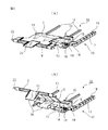
図1(a)は本出願の第1の実施形態のリンク機構31を備えた情報機器50の外観を示す斜視図である。情報機器50には第1の筐体としての本体部1と第2の筐体としてのディスプレイ部2があり、ディスプレイ部2にはタッチパネル付ディスプレイ20が設けられている。本体部1にディスプレイ部2が重ね合わされた状態では、タッチパネル付ディスプレイ20はディスプレイ部2の表側の面に露出している。そして、重ね合わされた本体部1とディスプレイ部2の両方の側面にはディスプレイ部2を本体部1からチルトさせるリンク機構31が取り付けられている。なお、以後の説明では、情報機器50を利用者が操作する側を情報機器50の前側とする。
Fig.1 (a) is a perspective view which shows the external appearance of the
第1の実施形態のリンク機構31は、図1(b)に示すように、第1回転軸11と第2回転軸22を両端に備えたリンク3と、リンク3の第1回転軸11を本体部1の側面でスライド及びロックするスライド機構4を備えている。スライド機構4には、本体部1の側面に設けられたスライド溝43、第1回転軸11を保持すると共にスライド溝43内を移動できる第1ブラケット41、及び第1ブラケット41をスライド溝43の任意の位置でロックするロック部材44がある。リンク3の第2回転軸22は、ディスプレイ部2がチルトする時の基部側のディスプレイ部2の側面に回転自在に設けられており、リンク3の第1回転軸11を保持する第1ブラケット41を備えるスライド機構4は情報機器50の後ろ側の本体部1の側面にある。
As shown in FIG. 1B, the
また、ディスプレイ部2のチルト時に下側となる下端部2Bには、チルト回転軸6に取り付けられた走行ローラ5があり、本体部1の上面には、走行ローラ5が本体部1の面上を移動して来た時に、チルト回転軸6の移動を係止する回転軸支持部7がある。
The
図1(c)に示すように、リンク機構31によって本体部1からディスプレイ部2がスライドとチルト動作を開始すると、本体部1とディスプレイ部2の間に掛け渡されたリンク3が第1回転軸11を中心にして回転する。そして、ディスプレイ部2の下端部2Bにある走行ローラ5が本体部1の上を走行すると、下端部2Bがスライド移動する。走行ローラ5が本体部1の上を走行するに伴ってディスプレイ部2の上端部2Tがチルトして行く。この時、リンク3の第1回転軸11はロック部材44によって第1ブラケット41がスライド溝43に固定されているので移動しない。
As shown in FIG. 1C, when the
図2(a)は図1(c)に示した状態からディスプレイ部2が更にチルトされ、走行ローラ5のチルト回転軸6が回転軸支持部7に係止されてチルト動作が完了した状態を示している。第1の実施形態のリンク機構31の動作によれば、本体部1からディスプレイ部2がチルトしてチルト動作が完了するまでの間に、ディスプレイ部2の上端部2Tが移動する軌跡Lは、本体部1の後ろ側の端部に立てた垂線Pより後ろ側に出ない。よって、第1の実施形態のリンク機構31が取り付けられた情報機器50は、本体部1の後ろ側にスペースのない場所でもディスプレイ部2をチルトさせることができる。
2A shows a state in which the
一方、第1の実施形態のリンク機構31が取り付けられた情報機器50は、本体部1の後ろ側にスペースがある場所では、ディスプレイ部2のチルト角度を、ディスプレイ部2の下端部2Bの位置を移動させることなく変更することができる。この動作を図2(b)を用いて説明する。図2(a)に示すように、ディスプレイ部2のチルトが完了した状態では、走行ローラ5のチルト回転軸6が回転軸支持部7に係止されている。この状態でスライド機構4のロック部材44のロックを外し、第1ブラケット41をスライド溝43内を本体部1の後ろ側に向かってスライドさせれば、図2(b)に示すように、ディスプレイ部2がチルト回転軸6を中心にして回転し、チルト角度を変更できる。
On the other hand, in the
次に、本出願の第2の実施形態のリンク機構32について説明する。第1の実施形態のリンク機構31は、本体部1とディスプレイ部2の両方の側面に取り付けられていたが、第2の実施形態のリンク機構32は、本体部1の上面とディスプレイ部2の裏面間に取り付けられる。図3(a)は情報機器に取り付ける第2の実施形態のリンク機構32の構造を示す分解斜視図である。
Next, the
第2の実施形態のリンク機構32は、一端に第1回転軸11、他端に第2回転軸22を備えるリンク3、第1ブラケット41、第2ブラケット42及び第2回転軸22に取り付けられた付勢手段であるアシストバネ9とを備えている。第2の実施形態では、リンク3は板状であり、ディスプレイ部側が拡幅されて端部に切欠部25が設けられている。第2回転軸22はこの切欠部25を横断して設けられ、その両端部が第2ブラケット42に軸支される。そして、切欠部25内に位置する第2回転軸22は、2つのアシストバネ9を挿通しており、第2回転軸22を軸支する第2ブラケット42はディスプレイ部2に取り付けられる。また、第1回転軸11はその両端部が第1ブラケット41に軸支され、第1ブラケット41は本体部1に取り付けられる。リンク3の形状はこの実施例の形状に限定されるものではない。
The
アシストバネ9には図3(b)に示すような捻りバネを使用することができる。アシストバネ9は、図3(c)に示すように、バネの両端が開いた状態でリンク3とディスプレイ部2の間に取り付けられる。アシストバネ9のディスプレイ部2側の端部は、押さえ板23とネジ24によってディスプレイ部2に固定される。図3(c)は本体部1にディスプレイ部2が重なった状態におけるリンク3の状態を示しており、この状態ではアシストバネ9は図3(b)に示す状態に戻ろうとするので、アシストバネ9によってリンクが矢印で示す方向に押される。矢印で示す方向は、リンク3の第1回転軸11がディスプレイ部2から離れる方向である。
As the
図4(a)は本体部1とディスプレイ部2の間に第2の実施形態のリンク機構32を備えた情報機器50の閉じた状態を示す斜視図であり、図5(a)は図4(a)のスケルトン図である。また、図6(a)は図5(a)のリンク機構32のみを取り出して拡大して示す斜視図であり、リンク機構32が閉じた状態を示している。図4(a)に示すように、本体部1に重ねられたディスプレイ部2の上面にはタッチパネル付ディスプレイ20が設けられている。また、本体部1とディスプレイ部2との電気的な接続は、図6(a)に示すように、リンク機構32のリンク3に沿って配設されるFPC(柔軟な回路基板)26によって行われる。更に、リンク機構32の後ろにはスライドプレート12、スライドレール13、スライドレバー14、ロック解除レバー15、ロック爪16、ロック溝19のあるレール17及びロック解除レバー付勢部材18を備えるスライドとロック機構10がある。スライドとロック機構10については後述する。
FIG. 4A is a perspective view showing a closed state of the
そして、本体部1とディスプレイ部2の間に第2の実施形態のリンク機構32が設けられていると、アシストバネ9によってリンク3の第2回転軸22が本体部1から離れる方向に付勢されるので、ディスプレイ部2は本体部1から開く方向に付勢される。このため、本体部1とディスプレイ部2の間には、図4(a)と図5(a)に示すように、クローズロック機構8が設けられており、情報機器50の本体部1にディスプレイ部2が重なった状態では、ディスプレイ部2が本体部1から開かないようになっている。クローズロック機構8の構造については後述する。
When the
図4(a)と図5(a)に示す情報機器50の本体部1にディスプレイ部2が重なった状態でクローズロック機構8によるロックを解除すると、リンク機構32によってディスプレイ部2が本体部1から開き始める。ディスプレイ部2が本体部1から開く時は、図4(b)に示す斜視図及び図5(b)に示すスケルトン図のように、リンク機構32によってディスプレイ部2が本体部1に対して自動的にスライドしながらチルトを開始する。図6(b)は図5(b)のリンク機構32のみを取り出して拡大して示す斜視図である。このとき、ディスプレイ部2の下端部2Bに設けられた走行ローラ5が本体部1の上面を走行し、ディスプレイ部2の上端部2Tが本体部1に対して次第にチルトしていく。
When the lock by the
図4(b)及び図5(b)に示した状態から、ディスプレイ部2の下端部2Bに設けられた走行ローラ5が本体部1の上面を更に走行すると、図4(c)の斜視図及び図5(c)のスケルトン図に示す状態になる。また、図7(a)は図5(c)のリンク機構32のみを取り出して拡大して示す斜視図である。この状態では、図5(c)に示すように、ディスプレイ部2の下端部2Bにある走行ローラ5の回転軸6が回転軸支持部7に係止され、ディスプレイ部2の下端部2Bはこれ以上本体部1の上をスライドせず、ディスプレイ部2のスライドとチルト動作が完了する。ディスプレイ部2のスライドとチルト動作が完了すると、本体部1の上面にキーボード21が現れる。また、図6(a)、(b)及び図7(a)から分かるように、リンク機構32に沿って配設されたFPC26は、リンク3の移動に伴って変形する。
When the traveling
ここで、リンク機構32の後ろ側に設けられ、第1回転軸11を軸支する第1ブラケット41をスライドさせて任意位置でロックするスライドとロック機構10について説明する。図8(a)はリンク機構32の本体部1側に設けられた第1回転軸11のスライドとロック機構10の構成を、本体部1とディスプレイ部2とが図5(a)に示した状態にある時の状態として示すものである。この状態は図6(a)にも示される。また、図8(b)は図8(a)に示したスライドとロック機構10を反対側から見たものである。更に、図8(c)は本体部1とディスプレイ部2とが図5(c)に示した状態にある時のスライドとロック機構10の状態を示すものである。この状態は図7(a)にも示される。
Here, the slide and the
スライドとロック機構10には、リンク3の第1回転軸11の両端を軸支する第1ブラケット41の間を繋ぐスライドプレート12があり、スライドプレート12の下面に設けられたスライダ27がスライドレール13の上をスライドするようになっている。スライドレール13は本体部1の上面に2本平行に配置されている。また、スライドレール13の一方の脇には、ロック溝19が設けられたロック溝付レール17が設けられており、スライドプレート12のロック溝付レール17側の端部には、このロック溝付レール17に係合するロックレバー機構30が設けられている。
The slide and
ロックレバー機構30は、スライドプレート12に一体的に設けられたスライドレバー14とロック解除レバー15及びロック溝付レール17のロック溝19に係合するロック爪16を備えるものであり、スライドとロック機構10の一部である。ロック解除レバー15は、スライドレバー14に対向する位置に、回転軸28によってスライドプレート12に取り付けられており、通常はバネ等のレバー付勢部材18によってスライドレバー14から離れる方向に付勢されている。ディスプレイ部2が本体部1に重なった状態から、ディスプレイ部2が本体部1に対してスライドとチルトされてチルト動作が完了までの状態では、図8(a)、(c)に示すように、ロック爪16はロック溝付レール17の基準溝19Rに係合している。
The
図9(a)は第2の実施形態のリンク機構32により、ディスプレイ部2が本体部1に対してスライドとチルト動作を完了した状態の情報機器50を裏面側から見たものである。本体部1の上面とディスプレイ部2の裏面には、本体部1にディスプレイ部2が重ね合わされた時にリンク機構32を収容する凹部1A,2Aが設けられている。ディスプレイ部2が本体部1に対してスライドとチルト動作を完了した状態では、本体部1の上面からロックレバー機構30のスライドレバー14とロック解除レバー15とが突出している。
FIG. 9A shows the
よって、本体部1に対するディスプレイ部2のチルト角度を変更する時には、情報機器50の利用者はスライドレバー14とロック解除レバー15とを指で摘み、ロック解除レバー15をスライドレバー14側に移動させる。ロック解除レバー15をスライドレバー14側に移動させると、図8(a)、(c)に示したロック爪16が基準溝19Rから外れるので、ロックレバー機構30がロック溝付レール17に対して自由に動けるようになる。そこで、摘んだスライドレバー14を図9(b)に示すように本体部1の後ろ側に移動させれば、スライドプレート12がスライドレール上を移動し、リンク3の角度が変るので、ディスプレイ部2のチルト角度を変更することができる。図9(c)は図9(b)に示した状態からスライドとロック機構10を動作させてディスプレイ部2の水平面からのチルト角を最小にした時のスライドとロック機構10及びロックレバー機構30の状態を示している。
Therefore, when the tilt angle of the
図10(a)は、図4(c)に示したディスプレイ部2のスライドとチルト動作が完了した状態から、ディスプレイ部2のチルト角を最大限変更した場合の情報機器50の状態を示すものである。また、図10(b)は図10(a)に示した状態におけるリンク機構32、走行ローラ5とその回転軸6、スライドとロック機構10、ロックレバー機構30及び回転軸支持部7の動作状態を示す情報機器50のスケルトン図である。更に、図7(b)は図10(b)のリンク機構32のみを取り出して拡大して示す斜視図である。図7(b)から分かるように、ディスプレイ部2のチルト角を最大限変更した場合は、ロックレバー機構30のロック爪16は、ロック溝付レール17の基準溝19Rから最も遠い位置にあるロック溝19に係合している。本体部1にある電気回路とディスプレイ部2にある電気回路とを接続するFPC26も、リンク機構32のリンク3の移動に応じて変形している。
FIG. 10A shows the state of the
図11(a)はディスプレイ部2を本体部1に係止するクローズロック機構8の一実施例の構成を分解して示すものである。クローズロック機構8には中空のケース80があり、ケース80の一端には開口部81がある。また、ケース80の上面には開口部81に連通する上面開口82がある。このケース80の内部には、開口部81からバネ83が挿入された後に、スライド部材84が挿入される。スライド部材84の両側面にはストッパ85が突設されており、スライド部材84はこのストッパ85が開口部81の縁部に当接するまでケース80の内部に押し込むことができる。更に、スライド部材84のストッパ85から遠い側の端部の上面にはロック突起86が設けられている。ロック突起86は、スライド部材84をケース80内に挿入する時に、上部開口82内に挿入される。そして、以上のような構成のクローズロック機構8では、スライド部材84のストッパ85が設けられた側の端面がロック解除ボタン87となる。
FIG. 11A shows an exploded configuration of an embodiment of the
図11(b)は図11(a)に示したクローズロック機構8が本体部1の内部に取り付けられ、ディスプレイ部2が本体部1にロックされている状態を示すものであり、スライド部材84の先端部がロック解除ボタン87として本体部1から突出している。本体部1に取り付けられたクローズロック機構8の直上の本体部1の筐体には、ディスプレイ部2の裏面に突設されたロックループ88を通すための孔1Bがある。ロックループ88はロック突起86に係止される係止部材であり、その形状と位置が図9(a)に示される。ディスプレイ部2が本体部1に重なった状態では、ディスプレイ部2にあるロックループ88がクローズロック機構8のロック突起86に係止されているので、ディスプレイ部2は本体部1から開かない。
FIG. 11B shows a state in which the
図11(b)に示した状態において、ロック解除ボタン87が図11(c)に示すように押されると、スライド部材84はストッパ85がケース80に当接するまでケース80の内部に押し込まれ、ロック突起86が上部開口82内を移動する。ロック突起86の移動により、ロック突起86からロックループ88が外れると、前述したリンク機構32により、本体部1に対してディスプレイ部2が開く。ロック解除ボタン87の押圧を止めると、スライド部材84は図11(b)に示した位置まで戻る。この状態でディスプレイ部2が本体部1の上に重ねられた場合は、ロックループ88がロック突起86に当接するが、ロック突起86の上面にはテーパー部があるので、ロックループ88がテーパー部を押してスライダをケース80内に没入させる。この動作により、ロックループ88がロック突起86にロックされた図11(b)に示す状態となる。
In the state shown in FIG. 11B, when the
図11(d)はディスプレイ部2の下端部2Bに設けられた走行ローラ5の一実施例の構成を示すものである。ディスプレイ部2の両側の下端部2Bには凹部2Cが設けられており、この凹部2C内に回転軸6に取り付けられた走行ローラ5がある。走行ローラ5の外周面は凹部2Cから僅かに突出しており、ディスプレイ部2がスライドとチルト動作を開始する時には、走行ローラ5が本体部1の上面に当接する。図11(e)は図11(d)に示した走行ローラ5の回転軸6が、本体部1の上面に突設された回転軸支持部7に係止された状態を示すものであり、例えば、図2(a)、図5(c)に示した回転軸6と回転軸支持部7との係合状態を部分拡大したものである。回転軸支持部7に係止された回転軸6がディスプレイ部2のチルト角を変更する際の回転軸となる。
FIG. 11 (d) shows the configuration of an embodiment of the traveling
以上説明した第2の実施形態のリンク機構32を取り付けた情報機器50では、図4(a)に示した本体部1にディスプレイ部2を重ねた状態での使用、図4(c)に示した本体部1からディスプレイ部2を起こしてチルトさせた状態での使用が可能である。更に、図10(a)に示した本体部1からディスプレイ部2を起こしてチルトさせた状態からディスプレイ部2のチルト角を変更する使用が可能である。図4(c)と図10(a)に示した状態では、キーボード21が露出しているので、情報機器50に対してキーボード21を用いた入力が可能である。
In the
一方、本体部1にタッチパネル付ディスプレイ20が設けられている場合には、図4(a)に示した状態で、タッチパネル付ディスプレイ20を用いた入力が可能である。そしてタッチパネル付ディスプレイ20を用いた入力を行う場合でも、図12(c)に示すように、ディスプレイ部2が本体部1に対して僅かにチルトしていた方が使い易い場合がある。そこで、第2の実施形態のリンク機構32に、ディスプレイ部2を図12(c)の状態にできるチルトロック機構を設けた実施例を図12から図14を用いて説明する。
On the other hand, when the
図12(a)は図5(a)に示したリンク機構32に、ディスプレイ部2の本体部1からのスライドとチルト動作を途中で停止させるチルトロック機構60が設けられた変形例のリンク機構32を備えた情報機器50のスケルトン図である。チルトロック機構60はリンク機構32のロック溝付レール17が設けられる側と反対側に設けられている。図12(b)は図12(c)に示した状態の時のチルトロック機構60の動作を示すスケルトン図である。クローズロック機構8のロックが解除され、リンク機構32によってディスプレイ部2が本体部1に対してスライドとチルト動作を開始すると、ディスプレイ部2が僅かにチルトした状態で、チルトロック機構60によりリンク機構32の動作が止められる。
12A shows a modified link mechanism in which the
図13(a)はチルトロック機構60が第2の実施形態のリンク機構32に取り付けられており、ディスプレイ部2が閉じた状態におけるスライドとロック機構10とチルトロック機構60を示すものである。スライドとロック機構10の構成については既に説明したので、同じ構成部材には同じ符号を付してその説明を省略する。チルトロック機構60は、本体部1の上に設置された本体65の上に回転軸68を中心にして揺動することができるロック解除レバー61を備えており、ロック解除レバー61には回転軸67に取り付けられたローラ63がある。
FIG. 13A shows the slide,
一方、リンク機構32のリンク3の本体部1側にある第1回転軸11には、ローラ63に係合するロックカム62が固着されている。ロックカム62には切欠部66が設けられており、ディスプレイ部2が本体部1に対して閉じた状態では、ローラ63がこの切欠部66の中にある。また、ロック解除レバー61は、本体65に設けられたレバー付勢部64によって、ロックカム62の方向に付勢されている。
On the other hand, a
クローズロック機構8のロックが解除され、リンク機構32によってディスプレイ部2が本体部1に対してスライドとチルト動作を開始すると、第1回転軸11が矢印で示す方向に回転する。ディスプレイ部2が本体部1に対してスライドとチルト動作を続けると、図13(b)に示すように、第1回転軸11に固着されたロックカム62の切欠部66の端面66Fがローラ63に当接する。すると第1回転軸11の回転が止められるので、ロックレバー機構30のリンク3の動作が止まり、ディスプレイ部2が本体部1に対してスライドとチルト動作をしなくなる。この状態が図12(b)、(c)に示した状態である。このように、リンク機構32にチルトロック機構60を取り付けると、ディスプレイ部2のスライドとチルト動作を途中で止めることが可能である。
When the lock of the
チルトロック機構60によるディスプレイ部2のスライドとチルト動作を途中で止める動作を解除する場合は、図14(a)に示すように、ロック解除レバー61をレバー付勢部64による付勢力に抗してレバー付勢部64側に回転させる。すると、ロック解除レバー61にあるローラ63がロックカム62の切欠部66から抜け出るので、ローラ63によるロックカム62の係止が解除され、第1回転軸11が矢印で示す方向への回転を再開することができる。ローラ63がロックカム62の切欠部66から抜け出し、第1回転軸11が矢印への回転を再開したら、ロック解除レバー61は開放することができる。ロック解除レバー61を開放した状態では、ローラ63はロックカム62の外周面の上を走行する。図14(a)は、チルトロック機構60によるディスプレイ部2のスライドとチルト動作の停止動作が解除された後に、ティスプレイ部2のスライドとチルト動作が完了した時の状態を示している。
When releasing the operation of stopping the sliding and tilting operation of the
チルトロック機構60は、リンク機構32の脇にリンク機構32とは独立に設けられている。従って、図14(b)に示すように、リンク機構32のスライドとロック機構10により、ティスプレイ部2のチルト角度を変更するためにスライドとロック機構10がレール13の上を移動しても、チルトロック機構60位置は変らない。
The
また、図14(a)に示す状態からディスプレイ部2が閉じられる時は、リンク機構32のリンク3に設けられた第1回転軸11は矢印と反対方向に回転する。この場合はローラ63はロックカム62の外周面の上を走行するので、ローラ63が切欠部66の位置まで来ても、ローラ63が切欠部66内に入るだけで、第1回転軸11の回転を止めない。よって、ディスプレイ部2が閉じられる時は、チルトロック機構60があってもディスプレイ部2を閉じる動作に影響はない。
When the
第2の実施形態のリンク機構32を本体部1とディスプレイ部2の間に備えた情報機器50は、図4(a)から図4(c)に示したように、クローズロック機構8を押すと、アシストバネの付勢力でディスプレイ部2が本体部1から開いてチルト状態になる。このとき、リンク機構32にダンパ機構を設けることにより、ディスプレイ部2が本体部1からゆっくり開いてチルト状態になるようにすることができる。そこで、第2の実施形態のリンク機構32に、ディスプレイ部2を本体部1からゆっくり開くようにすることができるダンパ機構を設けた実施例を図15から図18を用いて説明する。
The
図15(a)は第2の実施形態のリンク機構32にダンパ機構70が設けられた場合のリンク機構32の、図6(a)と同じ部位を示すものであり、ディスプレイ部が閉じた状態のリンク機構32を示している。また、図15(b)は図15(a)に示されるダンパ機構70が設けられたリンク機構32を反対側から見たものである。ダンパ機構70は、リンク機構32に設けられたロックレバー機構30と反対側に設けられる。
FIG. 15A shows the same part of the
ダンパ機構70は、リンク3の第1回転軸11に固着されたダンパカム71、ダンパ72、出没ロッド73及び接触子74を備えている。接触子74は出没ロッド73の先端部に取り付けられており、ディスプレイ部が閉じた状態からスライドとチルト動作を完了するまでの間、ダンパカム71の外周面に当接している。ダンパカム71の外周面の接触子74と当接する部分は、第1回転軸11からの距離がディスプレイ部が閉じた状態で最小になり、ディスプレイ部がチルトを完了した状態で最大になるように形成されている。接触子74はダンパカム71に押されると出没ロッド73をダンパ72内に没入させるが、ダンパ72は出没ロッド73をゆっくりした速度でダンパ72内に進入させる。また、出没ロッド73がダンパ72から出る時もゆっくりした速度で排出する。
The
図16(a)は、図15(a)に示した状態から、ディスプレイ部がスライドとチルト動作を行っている時のダンパ機構70の状態を示すものであり、図16(b)は図16(a)に示されるダンパ機構70が設けられたリンク機構32を反対側から見たものである。ディスプレイ部がスライドとチルト動作を行うと、第1回転軸11が回転してリンク3が立上がり、これに伴ってダンパカム71が回転する。ダンパカム71が回転すると、接触子74と当接する部分の第1回転軸11からの距離が長くなるので、接触子74が押されて出没ロッド73がダンパ72内に没入するが、ダンパ72の作用により接触子74の没入速度が抑えられる。この結果、リンク3の立ち上がり速度が低速になり、ディスプレイ部がゆっくりとスライドとチルト動作を行う。
FIG. 16A shows the state of the
図17(a)は、図16(a)に示した状態から、ディスプレイ部がスライドとチルト動作を更に行って、スライドとチルト動作が完了した時の状態を示すものである。また、図17(b)は図17(a)に示されるダンパ機構70が設けられたリンク機構32を反対側から見たものである。ディスプレイ部がスライドとチルト動作を完了するとリンク3の第1回転軸11の回転が止まり、ダンパカム71と接触子74と当接する部分の第1回転軸11からの距離が最も長くなり、出没ロッド73がダンパ72内に最大限没入する。このように、ディスプレイ部がスライドとチルト動作を行ってスライドとチルト完了位置に至るまでの間は、ダンパ72の作用により接触子74の没入速度が抑えられ、ディスプレイ部がゆっくりとチルト完了位置まで移動する。
FIG. 17A shows a state when the display unit further performs the slide and tilt operations from the state shown in FIG. 16A and the slide and tilt operations are completed. FIG. 17B shows the
なお、図17(a)、(b)に示したディスプレイ部のスライドとチルト完了位置から、図15(a)、(b)に示したディスプレイ部が閉じた状態に戻す時は、ダンパカム71はダンパ機構70の影響を受けないので、ディスプレイ部を素早く閉じることができる。そして、ディスプレイ部が閉じられた後に、出没ロッド73がゆっくりとダンパ72から押し出され、接触子74が後からダンパカム71に当接するようになる。
When the display unit shown in FIGS. 15 (a) and 15 (b) is returned to the closed state from the slide and tilt completion positions of the display unit shown in FIGS. 17 (a) and 17 (b), the
図18(a)は、図17(a)に示したディスプレイ部のスライドとチルト動作の完了状態から、ディスプレイ部のチルト角がスライドとロック機構10によって変更された時の状態を示すものである。また、図18(b)は図18(a)に示されるダンパ機構70が設けられたリンク機構32を反対側から見たものである。ダンパ機構70のダンパ72は本体部に固定されているので、ディスプレイ部のチルト角度がスライドとロック機構10によって変更される時には、ダンパ機構70はその動作に影響を与えない。
FIG. 18A shows a state when the tilt angle of the display unit is changed by the slide and
以上のように構成されたリンク機構を本体部とディスプレイ部との間に備えた情報機器には、以下のような効果がある。
(1)ディスプレイ部が本体部に重なった状態からチルトした状態まで1段階の操作で変化するため、操作感がスムーズである。
(2)チルト状態からさらにチルト角を変更できるので、利用者がディスプレイを見易い角度に設定できて使い勝手が向上する。
(3)ディスプレイ部が本体部に重なった状態からチルトした状態まで変化する際に、ディスプレイ部が本体部の上方空間から外に出ないので、狭い空間で操作できる。
(4)チルト状態からクローズ状態へ戻す時も1段階の操作で変身するので操作感がスムーズである。
(5)チルト状態から更にチルト角を変更する際に、ディスプレイ部の下端部が一定の位置に保持されているので、本体部のキーボードをディスプレイ部の下端近くまで配置することができ、キーボードの操作面を広くできてキーボードの操作性が向上する。
(6)第2の実施形態のリンク機構では、ディスプレイ部の裏側をリンクで支持しているためチルト状態でタッチパネルを操作した時にディスプレイ部がぐらつかず、タッチパネル操作時にディスプレイ部に剛性感があってタッチ操作を安定にできる。
The information device provided with the link mechanism configured as described above between the main body portion and the display portion has the following effects.
(1) Since the display unit changes from a state where the display unit is overlapped with the main body unit to a state where the display unit is tilted, the operation feeling is smooth.
(2) Since the tilt angle can be further changed from the tilt state, the user can set the angle so that the user can easily see the display, and the usability is improved.
(3) When the display unit changes from a state where it overlaps the main body unit to a tilted state, the display unit does not go out of the upper space of the main body unit, so that it can be operated in a narrow space.
(4) Even when returning from the tilted state to the closed state, the operation feeling is smooth because the transformation is performed in one step.
(5) When the tilt angle is further changed from the tilted state, the lower end portion of the display unit is held at a fixed position, so that the keyboard of the main body unit can be arranged near the lower end of the display unit. The operation surface can be widened and the operability of the keyboard is improved.
(6) In the link mechanism of the second embodiment, since the back side of the display unit is supported by the link, the display unit does not wobble when the touch panel is operated in the tilted state, and the display unit has a sense of rigidity when the touch panel is operated. Touch operation can be stabilized.
以上、本出願を特にその好ましい実施の実施形態を参照して詳細に説明した。本出願の容易な理解のために、本出願の具体的な実施形態を以下に付記する。 The present application has been described in detail with particular reference to preferred embodiments thereof. For easy understanding of the present application, specific embodiments of the present application are appended below.
(付記1) 第1筐体及び第2筐体と、
前記第1筐体に前記第2筐体が重なった状態で、前記第2筐体の手前側から前記第1筐体の後ろ側に掛け渡されたリンク機構とを備えた情報機器であって、
前記リンク機構は、一端に第1回転軸、他端に第2回転軸を備えるリンク、前記第1回転軸を軸支する前記第1筐体側に設けられた第1ブラケット、前記第2回転軸を軸支する前記第2筐体側に設けられた第2ブラケット、及び前記第2回転軸が前記第1筐体から離れる方向に前記リンクを付勢する付勢手段を備え、
前記第2筐体の前記第1筐体からのチルト時には、前記リンク機構により前記第2筐体の一端が前記第1筐体上をスライド移動し、前記第2筐体が前記第1筐体の上方空間内でチルトすることを特徴とする情報機器。
(付記2) 前記第1筐体と前記第2筐体の間に、前記第1筐体に前記第2筐体が重なった状態で、前記前記第2筐体を前記第1筐体上に固定するロック機構が設けられ、
前記ロック機構のロックを解除すると前記付勢手段により、前記第2筐体が第1筐体から自動的にチルトすることを特徴とする付記1に記載の情報機器。
(付記3) 前記第1筐体側に、前記リンクが前記第1回転軸を中心にして回転移動する際の回転速度を弱めるダンパ機構が設けられていることを特徴とする付記1又は2に記載の情報機器。
(付記4) 前記第1筐体の上に、前記第2筐体の一端が前記第1筐体上をスライド移動してきた時に、前記第2筐体の一端のスライド移動を係止する係止機構が設けられていることを特徴とする付記1から3の何れかに記載の情報機器。
(付記5) 前記第2筐体の一端の、前記第1筐体上をスライド移動する部位には回転軸に取り付けられた走行ローラが設けられており、
前記係止機構は前記走行ローラの回転軸を係止することを特徴とする付記4に記載の情報機器。
(Appendix 1) a first housing and a second housing;
An information device comprising: a link mechanism that spans from the front side of the second casing to the rear side of the first casing in a state where the second casing overlaps the first casing. ,
The link mechanism includes a link having a first rotation shaft at one end and a second rotation shaft at the other end, a first bracket provided on the first housing side that supports the first rotation shaft, and the second rotation shaft. A second bracket provided on the side of the second casing that pivotally supports and a biasing means that biases the link in a direction in which the second rotating shaft is separated from the first casing;
When the second casing is tilted from the first casing, one end of the second casing is slid on the first casing by the link mechanism, and the second casing is moved to the first casing. An information device characterized by tilting in the space above.
(Supplementary Note 2) The second casing is placed on the first casing in a state where the second casing overlaps the first casing between the first casing and the second casing. A locking mechanism is provided for fixing,
2. The information apparatus according to
(Supplementary note 3) The
(Supplementary Note 4) When the one end of the second casing slides on the first casing on the first casing, the latch for locking the sliding movement of the one end of the second casing 4. The information device according to any one of
(Supplementary Note 5) A traveling roller attached to a rotating shaft is provided at a part of the one end of the second casing that slides on the first casing.
The information device according to claim 4, wherein the locking mechanism locks the rotation shaft of the traveling roller.
(付記6) 前記第1筐体側に前記第1ブラケットのスライド機構が設けられており、
前記スライド機構は、前記第2筐体が前記第1筐体からチルトした状態で、前記第1回転軸を前記第2筐体の一端から離れる方向に移動可能であり、
前記第1回転軸の前記第2筐体の一端から離れる方向への移動により、前記第2筐体は前記係止機構に係止された前記走行ローラの回転軸を中心に回転してチルト角が変更されることを特徴とする付記5に記載の情報機器。
(付記7) 前記スライド機構は、前記第1ブラケットを移動させるスライドレールと、前記第1ブラケットを前記第1筐体に前記第2筐体が重なった状態と前記第2筐体が前記第1筐体からチルトする時に固定し、前記第1ブラケットが前記スライドレール上を移動する時に前記第1ブラケットの移動を段階的に係止するスライドとロック機構とを備えることを特徴とする付記6に記載の情報機器。
(付記8) 前記スライドとロック機構は、前記スライドレールに平行に前記第1筐体側に取り付けられたロック溝付のレールと、前記ロック溝付のレールの溝に係合離脱可能で前記第1ブラケットに取り付けられたロックレバー機構とを備えることを特徴とする付記7に記載の情報機器。
(付記9) 前記ロックレバー機構は、前記第1ブラケットに設けられたスライドレバーと、前記スライドレバーに対して揺動し、前記ロック溝付のレールの溝に係合離脱可能なロック爪とを備えることを特徴とする付記8に記載の情報機器。
(付記10) 前記第1ブラケットの近傍に、前記第2筐体が前記第1筐体からチルト開始した後の前記第1回転軸の回転を、回転角が小さい状態で止めて、前記第2筐体のチルト角を小さい状態にするチルトロック機構が設けられていることを特徴とする付記1から9の何れかに記載の情報機器。
(Additional remark 6) The slide mechanism of the said 1st bracket is provided in the said 1st housing | casing side,
The slide mechanism can move the first rotation shaft in a direction away from one end of the second casing in a state where the second casing is tilted from the first casing.
As the first rotating shaft moves away from one end of the second casing, the second casing rotates about the rotating shaft of the traveling roller locked by the locking mechanism, and the tilt angle The information device according to
(Supplementary Note 7) The slide mechanism includes a slide rail that moves the first bracket, a state in which the first bracket is overlapped with the first housing, and the second housing is the first housing.
(Supplementary Note 8) The slide and lock mechanism can be engaged and disengaged with a rail with a lock groove attached to the first housing side in parallel with the slide rail and a groove of the rail with the lock groove. The information apparatus according to
(Supplementary Note 9) The lock lever mechanism includes a slide lever provided in the first bracket, and a lock claw that swings with respect to the slide lever and that can be engaged with and disengaged from the groove of the rail with the lock groove. The information apparatus according to
(Supplementary Note 10) In the vicinity of the first bracket, the rotation of the first rotation shaft after the second housing starts tilting from the first housing is stopped in a state where the rotation angle is small, and the second housing The information device according to any one of
(付記11) 前記チルトロック機構にはロック解除レバーが設けられており、前記ロック解除レバーの操作により、前記第2筐体は前記第2筐体の一端が前記係止機構によって係止される位置までチルトすることを特徴とする付記10に記載の情報機器。
(付記12) 前記リンク機構は、前記第1筐体と前記第2筐体の側面において前記第1筐体と前記第2筐体とを連結することを特徴とする付記1から7の何れかに記載の情報機器。
(付記13) 前記リンク機構は、前記第1筐体の上面と前記第2筐体の裏面との間に設けられて、前記第1筐体と前記第2筐体とを連結することを特徴とする付記1から11の何れかに記載の情報機器。
(付記14) 前記第2筐体を前記第1筐体に対してスライドとチルトさせた時に現れる前記第1筐体の表面にはキーボードが設けられていることを特徴とする付記1から13の何れかに記載の情報機器。
(付記15) 第1と第2筐体間に配設され、重なった状態の前記第1と第2筐体から前記第2筐体を、前記第1筐体の上方空間内でチルトさせる情報機器のリンク機構であって、
一端に第1回転軸、他端に第2回転軸を備えるリンクと、
前記第1回転軸を軸支する前記第1筐体側上に設けられた第1ブラケットと、
前記第2回転軸を軸支する前記第2筐体側上に設けられた第2ブラケットと、
前記第2回転軸が前記第1筐体から離れる方向に前記リンクを付勢する付勢手段とを備え、
前記第1ブラケットが前記第2筐体のチルトアップ側の前記第1筐体に取り付けられ、前記第2ブラケットが前記第2筐体のチルト時の基部側の前記第2筐体に取り付けられた時に、前記第2筐体の前記第1筐体からのチルト時には、前記付勢手段によって前記第2筐体の一端を前記第1筐体上をスライド移動させてチルト動作を行わせることを特徴とする情報機器のリンク機構。
(Supplementary Note 11) The tilt lock mechanism is provided with a lock release lever, and one end of the second case is locked by the lock mechanism by the operation of the lock release lever. The information device according to
(Supplementary note 12) Any one of
(Additional remark 13) The said link mechanism is provided between the upper surface of the said 1st housing | casing, and the back surface of the said 2nd housing | casing, and connects the said 1st housing | casing and the said 2nd housing | casing. The information device according to any one of
(Appendix 14) The keyboard according to any one of
(Supplementary Note 15) Information that is disposed between the first and second housings and tilts the second housing from the first and second housings in an overlapping state in the space above the first housing. A device link mechanism,
A link having a first rotating shaft at one end and a second rotating shaft at the other end;
A first bracket provided on the first housing side that supports the first rotation shaft;
A second bracket provided on the second housing side for supporting the second rotation shaft;
Urging means for urging the link in a direction in which the second rotating shaft is separated from the first housing;
The first bracket is attached to the first case on the tilt-up side of the second case, and the second bracket is attached to the second case on the base side when the second case is tilted. Sometimes, when the second casing is tilted from the first casing, the biasing means slides one end of the second casing on the first casing to perform a tilting operation. Link mechanism of information equipment.
(付記16) 前記第1筐体の上に、前記リンクが前記第1回転軸を中心にして回転移動する際の回転速度を弱めるダンパ機構が設けられていることを特徴とする付記15に記載の情報機器のリンク機構。
(付記17) 前記第1ブラケットには、前記第1ブラケットを前記第1筐体の上で移動させるスライド機構が設けられており、
前記スライド機構は、前記第2筐体が前記第1筐体からチルト完了した状態で、前記第1ブラケットを前記第1筐体の上で移動させることを特徴とする付記15に記載の情報機器のリンク機構。
(付記18) 前記スライド機構は、前記第1ブラケットを移動させるスライドレールと、前記第1ブラケットを前記第1筐体に前記第2筐体が重なった状態と前記第2筐体が前記第1筐体からチルトする時に固定し、前記第1ブラケットが前記スライドレール上を移動する時に前記第1ブラケットの移動を段階的に係止するスライドロック機構とを備えることを特徴とする付記17に記載の情報機器のリンク機構。
(付記19) 前記スライドロック機構は、前記スライドレールに平行に前記第1筐体側に取り付けられたロック溝付のレールと、前記ロック溝付のレールの溝に係合離脱可能で前記第1ブラケットに取り付けられたロックレバー機構とを備えることを特徴とする付記18に記載の情報機器のリンク機構。
(付記20) 前記ロックレバー機構は、前記第1ブラケットに設けられたスライドレバーと、前記スライドレバーに対して揺動し、前記ロック溝付のレールの溝に係合離脱可能なロック爪とを備えることを特徴とする付記17に記載の情報機器のリンク機構。
(Supplementary note 16) The
(Supplementary Note 17) The first bracket is provided with a slide mechanism for moving the first bracket on the first housing.
16. The information device according to
(Supplementary Note 18) The slide mechanism includes a slide rail for moving the first bracket, a state in which the second housing overlaps the first housing with the first bracket, and the second housing is the first. The slide lock mechanism that is fixed when tilting from the housing and that locks the movement of the first bracket in a stepwise manner when the first bracket moves on the slide rail. Information equipment link mechanism.
(Supplementary Note 19) The slide lock mechanism can be engaged and disengaged from a rail with a lock groove attached to the first housing side in parallel to the slide rail, and a groove of the rail with the lock groove. 19. A link mechanism for an information device according to
(Supplementary Note 20) The lock lever mechanism includes a slide lever provided in the first bracket, and a lock claw that swings with respect to the slide lever and that can be engaged with and disengaged from the groove of the rail with the lock groove. 18. A link mechanism for an information device according to
1 第1筐体(本体部)
2 第2筐体(ディスプレイ部)
3 リンク
4 スライド機構
5 走行ローラ
6 回転軸
7 回転軸支持部
8 クローズロック機構
9 アシストバネ
10 スライドとロック機構
11 第1回転軸
13 スライドレール
17 ロック溝付レール
22 第2回転軸
30 ロックレバー機構
31,32 リンク機構
41,42 ブラケット
50 情報機器
60 チルトロック機構
70 ダンパ機構
1 First housing (main body)
2 Second housing (display unit)
3 Link 4
Claims (5)
前記リンク機構は、一端に第1回転軸、他端に第2回転軸を備えるリンクを備え、
前記第1回転軸は、前記第1筐体の中央部よりも後ろ側に設けられた第1ブラケットに軸支され、
前記第2回転軸は、前記第2筐体の中央部よりも手前側に設けられた第2ブラケットに軸支され、
前記第2回転軸には、前記第2回転軸が前記第1筐体から離れる方向に前記リンクを付勢する付勢手段が取り付けられており、
前記第2筐体の前記第1筐体からのチルト時には、前記リンク機構により前記第2筐体の一端が前記第1筐体上をスライド移動し、前記第2筐体の他端が前記第1筐体の上方空間よりも後ろ側に出ない範囲内でチルトすることを特徴とする情報機器。 A first housing and a second housing, and a link mechanism spanned between the first housing and the second housing in a state where the second housing overlaps the first housing. Information equipment
Wherein the link mechanism includes a first rotary shaft at one end, the link comprising a second rotating shaft at the other end,
The first rotation shaft is pivotally supported by a first bracket provided behind the center portion of the first housing ,
The second rotation shaft is pivotally supported by a second bracket provided on the front side of the center portion of the second housing ,
An urging means for urging the link in a direction in which the second rotation shaft is separated from the first housing is attached to the second rotation shaft.
When the second casing is tilted from the first casing, one end of the second casing is slid on the first casing by the link mechanism, and the other end of the second casing is the first casing. An information device that tilts within a range that does not protrude behind the upper space of one housing.
前記係止機構は前記走行ローラの回転軸を係止することを特徴とする請求項2に記載の情報機器。 A traveling roller attached to a rotating shaft is provided at a part of the one end of the second casing that slides on the first casing.
The information device according to claim 2, wherein the locking mechanism locks a rotation shaft of the traveling roller.
前記スライド機構は、前記第2筐体が前記第1筐体からチルトした状態で、前記第1回転軸を前記第2筐体の一端から離れる方向に移動可能であり、
前記第1回転軸の前記第2筐体の一端から離れる方向への移動により、前記第2筐体は前記係止機構に係止された前記走行ローラの回転軸を中心に回転してチルト角が変更されることを特徴とする請求項3に記載の情報機器。 A slide mechanism for the first bracket is provided on the first housing side;
The slide mechanism can move the first rotation shaft in a direction away from one end of the second casing in a state where the second casing is tilted from the first casing.
As the first rotating shaft moves away from one end of the second casing, the second casing rotates about the rotating shaft of the traveling roller locked by the locking mechanism, and the tilt angle The information device according to claim 3, wherein the information device is changed.
一端に第1回転軸、他端に第2回転軸を備えるリンクと、
前記第1回転軸を軸支する前記第1筐体側上に設けられた第1ブラケットと、
前記第2回転軸を軸支する前記第2筐体側上に設けられた第2ブラケットと、
前記第2回転軸が前記第1筐体から離れる方向に前記リンクを付勢する付勢手段とを備え、
前記第1ブラケットが前記第2筐体のチルトアップ側の前記第1筐体の中央部よりも後ろ側に取り付けられ、前記第2ブラケットが前記第2筐体のチルト時の基部側の前記第2筐体の中央部よりも手前側に取り付けられた時に、前記第2筐体の前記第1筐体からのチルト時には、前記付勢手段によって前記第2筐体の一端を前記第1筐体上をスライド移動させてチルト動作を行わせることを特徴とする情報機器のリンク機構。 A link mechanism for an information device, which is disposed between the first and second housings and tilts the second housing from the first and second housings in an overlapping state within the space above the first housing. Because
A link having a first rotating shaft at one end and a second rotating shaft at the other end;
A first bracket provided on the first housing side that supports the first rotation shaft;
A second bracket provided on the second housing side for supporting the second rotation shaft;
Urging means for urging the link in a direction in which the second rotating shaft is separated from the first housing;
The first bracket is attached to the rear side of the center portion of the first casing on the tilt-up side of the second casing, and the second bracket is located on the base side when the second casing is tilted. When the second housing is tilted from the first housing when attached to the front side of the central portion of the two housings, one end of the second housing is connected to the first housing by the biasing means. A link mechanism for an information device, characterized in that a tilt operation is performed by sliding and moving up.
Priority Applications (5)
| Application Number | Priority Date | Filing Date | Title |
|---|---|---|---|
| JP2012252534A JP6065537B2 (en) | 2012-11-16 | 2012-11-16 | Information device and information device link mechanism |
| US13/966,695 US9380719B2 (en) | 2012-11-16 | 2013-08-14 | Information apparatus and link mechanism of information apparatus |
| TW102130044A TWI545423B (en) | 2012-11-16 | 2013-08-22 | Information apparatus and link mechanism of information apparatus |
| EP13181783.5A EP2733568B1 (en) | 2012-11-16 | 2013-08-27 | Information apparatus and link mechanism of information apparatus |
| CN201310425040.6A CN103823518B (en) | 2012-11-16 | 2013-09-17 | Information equipment and the linkage of information equipment |
Applications Claiming Priority (1)
| Application Number | Priority Date | Filing Date | Title |
|---|---|---|---|
| JP2012252534A JP6065537B2 (en) | 2012-11-16 | 2012-11-16 | Information device and information device link mechanism |
Publications (2)
| Publication Number | Publication Date |
|---|---|
| JP2014102576A JP2014102576A (en) | 2014-06-05 |
| JP6065537B2 true JP6065537B2 (en) | 2017-01-25 |
Family
ID=49118294
Family Applications (1)
| Application Number | Title | Priority Date | Filing Date |
|---|---|---|---|
| JP2012252534A Active JP6065537B2 (en) | 2012-11-16 | 2012-11-16 | Information device and information device link mechanism |
Country Status (5)
| Country | Link |
|---|---|
| US (1) | US9380719B2 (en) |
| EP (1) | EP2733568B1 (en) |
| JP (1) | JP6065537B2 (en) |
| CN (1) | CN103823518B (en) |
| TW (1) | TWI545423B (en) |
Families Citing this family (22)
| Publication number | Priority date | Publication date | Assignee | Title |
|---|---|---|---|---|
| TWI502312B (en) * | 2012-02-24 | 2015-10-01 | First Dome Corp | A lifting device for the movement of auxiliary electronic objects |
| US9326400B2 (en) * | 2014-05-19 | 2016-04-26 | Anker Technology Co., Limited | Bracket apparatus applicable to keyboard and keyboard comprising the bracket apparatus |
| DE102014118752A1 (en) * | 2014-06-24 | 2015-12-24 | Beijing Lenovo Software Ltd. | Laptop |
| CN106462182B (en) * | 2014-06-30 | 2020-03-17 | 惠普发展公司有限责任合伙企业 | Linkage mechanism for a computing device having a rotatable display member |
| JP6418550B2 (en) * | 2014-08-15 | 2018-11-07 | 富士通クライアントコンピューティング株式会社 | Electronic equipment and arm device |
| US10474409B2 (en) * | 2014-09-19 | 2019-11-12 | Lenovo (Beijing) Co., Ltd. | Response control method and electronic device |
| CN105630101A (en) * | 2014-11-26 | 2016-06-01 | 鸿富锦精密工业(武汉)有限公司 | Electronic device shell and electronic device |
| CN104332000B (en) * | 2014-11-27 | 2016-06-29 | 广州御银自动柜员机技术有限公司 | A kind of support arrangement supporting movement planker in automatic teller machine |
| US9943017B2 (en) * | 2015-04-30 | 2018-04-10 | Premier Mounts | Enclosure device for displays |
| KR101756141B1 (en) * | 2015-05-12 | 2017-07-12 | 주식회사 다이아벨 | Slim Type Tilting Hinge and Electric Device having it |
| KR101756147B1 (en) * | 2015-05-12 | 2017-07-12 | 주식회사 다이아벨 | Slim Type Tilting Hinge and Electric Device having it |
| US9413863B1 (en) * | 2015-05-13 | 2016-08-09 | Hong Fu Jin Precision Industry (Wuhan) Co., Ltd. | Video phone with viewing stand |
| JP6643742B2 (en) * | 2017-01-24 | 2020-02-12 | 富士通クライアントコンピューティング株式会社 | Information processing device |
| JP6611839B2 (en) * | 2017-03-06 | 2019-11-27 | キヤノン株式会社 | Electronics |
| CN107461572A (en) * | 2017-10-16 | 2017-12-12 | 从佳乐 | A kind of industrial machinery supporting construction |
| JP2019198985A (en) * | 2018-05-14 | 2019-11-21 | 東芝テック株式会社 | Processing terminal |
| CN109140178B (en) * | 2018-08-17 | 2020-06-26 | 广东嘉晖盛科技股份有限公司 | New generation information technology display screen |
| TWI697818B (en) * | 2018-08-23 | 2020-07-01 | 緯創資通股份有限公司 | Portable electronic device and method of controlling a display screen of a display module |
| US10936020B2 (en) * | 2018-08-24 | 2021-03-02 | Compal Electronics, Inc. | Electronic device and expansion device |
| CN112616271B (en) * | 2020-12-01 | 2022-01-28 | 郑州铁路职业技术学院 | Railway signal machine protection device |
| US11681333B2 (en) * | 2021-06-10 | 2023-06-20 | Mobile Pixels Inc. | Foldable auxiliary monitor |
| CN114044175B (en) * | 2021-10-30 | 2023-05-26 | 西南电子技术研究所(中国电子科技集团公司第十研究所) | On-orbit dragging-off tool for chassis in manned space capsule |
Family Cites Families (22)
| Publication number | Priority date | Publication date | Assignee | Title |
|---|---|---|---|---|
| JP2734033B2 (en) * | 1988-08-08 | 1998-03-30 | ソニー株式会社 | Display device support mechanism |
| JP3102036B2 (en) | 1990-12-19 | 2000-10-23 | 富士通株式会社 | Display device support mechanism |
| JPH0566715A (en) * | 1991-09-06 | 1993-03-19 | Alps Electric Co Ltd | Flat display supporting mechanism |
| GB9825108D0 (en) * | 1998-11-16 | 1999-01-13 | Checkout Computer Systems Limi | Computer displays |
| JP2002055736A (en) | 2000-08-10 | 2002-02-20 | Toshiba Corp | Electronic equipment |
| KR100406487B1 (en) * | 2001-06-05 | 2003-11-17 | 엘지전자 주식회사 | Grade control apparatus of display set for tapestry |
| US6604722B1 (en) * | 2002-06-10 | 2003-08-12 | Seng-Ling Tan | Display support |
| WO2007114584A1 (en) * | 2006-04-04 | 2007-10-11 | Laird Technologies Map Co., Ltd. | Slide-up opening and closing mechanism for portable terminal |
| TWI327264B (en) * | 2007-01-19 | 2010-07-11 | Asustek Comp Inc | Handheld electronic device |
| TW200848983A (en) * | 2007-06-05 | 2008-12-16 | Asustek Comp Inc | Portable electronic device |
| TWI364647B (en) * | 2007-07-13 | 2012-05-21 | Asustek Comp Inc | Overturning cover mechanism and electronic device using the same |
| JP5129686B2 (en) * | 2008-08-06 | 2013-01-30 | 加藤電機株式会社 | Portable device and opening / closing device of the portable device |
| CN102292965A (en) * | 2008-12-19 | 2011-12-21 | 诺基亚公司 | Portable electronic device with slide and tilt mechanism |
| CN102131363B (en) * | 2010-01-15 | 2014-10-29 | 深圳富泰宏精密工业有限公司 | Electronic device |
| TW201224713A (en) * | 2010-12-02 | 2012-06-16 | Compal Electronics Inc | Mobile electronic device |
| US8272104B2 (en) * | 2011-02-25 | 2012-09-25 | Lianhong Art Co., Ltd. | Hinge-slide cover mounting structure using a sheet metal bracket mechanism |
| US8250711B1 (en) * | 2011-04-27 | 2012-08-28 | Lianhong Art Co., Ltd. | Space-saving slide cover lifting structure |
| US8559623B2 (en) * | 2011-06-09 | 2013-10-15 | Lianhong Art Co., Ltd. | Double sliding stability space-saving slide cover lifting structure |
| TWI462682B (en) * | 2012-01-12 | 2014-11-21 | Wistron Corp | Connecting mechanism and related electronic device |
| TWI458418B (en) * | 2012-02-06 | 2014-10-21 | Wistron Corp | Flat cable arranging structure and slider electronic apparatus therewith |
| TWM434422U (en) * | 2012-03-13 | 2012-07-21 | Wistron Corp | Supporting device and electronic device having supporting device |
| JP6094237B2 (en) * | 2013-02-01 | 2017-03-15 | 富士通株式会社 | IT equipment tilt mechanism |
-
2012
- 2012-11-16 JP JP2012252534A patent/JP6065537B2/en active Active
-
2013
- 2013-08-14 US US13/966,695 patent/US9380719B2/en active Active
- 2013-08-22 TW TW102130044A patent/TWI545423B/en active
- 2013-08-27 EP EP13181783.5A patent/EP2733568B1/en active Active
- 2013-09-17 CN CN201310425040.6A patent/CN103823518B/en active Active
Also Published As
| Publication number | Publication date |
|---|---|
| TW201421207A (en) | 2014-06-01 |
| TWI545423B (en) | 2016-08-11 |
| JP2014102576A (en) | 2014-06-05 |
| US20140139987A1 (en) | 2014-05-22 |
| EP2733568B1 (en) | 2018-05-02 |
| US9380719B2 (en) | 2016-06-28 |
| CN103823518A (en) | 2014-05-28 |
| EP2733568A2 (en) | 2014-05-21 |
| EP2733568A3 (en) | 2016-08-17 |
| CN103823518B (en) | 2017-03-01 |
Similar Documents
| Publication | Publication Date | Title |
|---|---|---|
| JP6065537B2 (en) | Information device and information device link mechanism | |
| JP6094237B2 (en) | IT equipment tilt mechanism | |
| JP4868705B2 (en) | Movable console device | |
| JP5910409B2 (en) | Information device and information device link mechanism | |
| RU2382864C1 (en) | Pull-out module fixed on hinges and pull-out device, where it is used | |
| US9678535B2 (en) | Moveable keyboard lattice for a portable electronic device | |
| TWI364647B (en) | Overturning cover mechanism and electronic device using the same | |
| JP2012233391A (en) | Hood latch device for vehicle | |
| US20100016043A1 (en) | Slide Mechanism and Electronic Apparatus | |
| JP2014232386A (en) | Electronic device | |
| JP6310694B2 (en) | Biaxial hinge device | |
| TWI524835B (en) | Automatic latching device and electrical device thereof | |
| JPH06230852A (en) | Information processor | |
| JP5289362B2 (en) | Movable console device | |
| TW201238441A (en) | Sliding mechanism and sliding-type touch pad and portable terminal | |
| JP6136496B2 (en) | Electronics | |
| JP2010086127A (en) | Portable electronic equipment | |
| JP4667622B2 (en) | Transfer mechanism and display device | |
| JP2010211111A (en) | Keyboard cover device for keyboard instrument | |
| JPH04273365A (en) | Electronic system notebook device | |
| JP4208443B2 (en) | Key slide mechanism | |
| JP2010135923A (en) | Folding type mobile terminal | |
| JP2002099354A (en) | Portable electronic equipment | |
| JP2010199653A (en) | Slide rotating mechanism | |
| JP2012186671A (en) | Terminal device |
Legal Events
| Date | Code | Title | Description |
|---|---|---|---|
| A621 | Written request for application examination |
Free format text: JAPANESE INTERMEDIATE CODE: A621 Effective date: 20150706 |
|
| A977 | Report on retrieval |
Free format text: JAPANESE INTERMEDIATE CODE: A971007 Effective date: 20160622 |
|
| A131 | Notification of reasons for refusal |
Free format text: JAPANESE INTERMEDIATE CODE: A131 Effective date: 20160628 |
|
| A521 | Request for written amendment filed |
Free format text: JAPANESE INTERMEDIATE CODE: A523 Effective date: 20160826 |
|
| TRDD | Decision of grant or rejection written | ||
| A01 | Written decision to grant a patent or to grant a registration (utility model) |
Free format text: JAPANESE INTERMEDIATE CODE: A01 Effective date: 20161129 |
|
| A61 | First payment of annual fees (during grant procedure) |
Free format text: JAPANESE INTERMEDIATE CODE: A61 Effective date: 20161212 |
|
| R150 | Certificate of patent or registration of utility model |
Ref document number: 6065537 Country of ref document: JP Free format text: JAPANESE INTERMEDIATE CODE: R150 |