JP6064597B2 - Automatic transaction equipment - Google Patents
Automatic transaction equipment Download PDFInfo
- Publication number
- JP6064597B2 JP6064597B2 JP2012287863A JP2012287863A JP6064597B2 JP 6064597 B2 JP6064597 B2 JP 6064597B2 JP 2012287863 A JP2012287863 A JP 2012287863A JP 2012287863 A JP2012287863 A JP 2012287863A JP 6064597 B2 JP6064597 B2 JP 6064597B2
- Authority
- JP
- Japan
- Prior art keywords
- bill press
- guide portion
- main body
- bill
- pickup roller
- Prior art date
- Legal status (The legal status is an assumption and is not a legal conclusion. Google has not performed a legal analysis and makes no representation as to the accuracy of the status listed.)
- Active
Links
Images


Classifications
-
- G—PHYSICS
- G07—CHECKING-DEVICES
- G07D—HANDLING OF COINS OR VALUABLE PAPERS, e.g. TESTING, SORTING BY DENOMINATIONS, COUNTING, DISPENSING, CHANGING OR DEPOSITING
- G07D11/00—Devices accepting coins; Devices accepting, dispensing, sorting or counting valuable papers
- G07D11/10—Mechanical details
- G07D11/14—Inlet or outlet ports
Landscapes
- Physics & Mathematics (AREA)
- General Physics & Mathematics (AREA)
- Sheets, Magazines, And Separation Thereof (AREA)
- Pile Receivers (AREA)
Description
本発明は、自動取引装置に関し、例えば、紙葉類(紙幣)を扱う装置に関するものである。 The present invention relates to an automatic transaction apparatus, for example, an apparatus for handling paper sheets (banknotes).
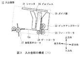
従来、自動取引装置においては、図13に示すように、顧客との間で紙幣のやり取りをする入出金部300は、紙幣の束(以下、これを紙幣束とも呼ぶ)BLWを収容する収容空間を形成するビルプレス301及びガイド部302が設けられる。 Conventionally, in an automatic transaction apparatus, as shown in FIG. 13, a deposit / withdrawal unit 300 for exchanging bills with a customer accommodates a bill bundle (hereinafter also referred to as a bill bundle) BLW. A bill press 301 and a guide portion 302 are provided.
入出金部300は、収容空間に投入された紙幣束BLWをガイド部302側に設けられるピックアップローラ303(303a、303b)にビルプレス301により押し当て、該ピックアップローラ303により収納庫等に繰り出すようになされている(例えば、特許文献1参照)。 The deposit / withdrawal unit 300 presses the bill bundle BLW put into the accommodation space against a pickup roller 303 (303a, 303b) provided on the guide unit 302 side by a bill press 301 and feeds it out to a storage or the like by the pickup roller 303. (For example, refer to Patent Document 1).
ところで、従来の入出金部300では、ビルプレス301における収容空間を形成する平坦な面に紙幣束BLWが当接するため、図8に示すような紙幣の長手方向に厚さが異なる紙幣束BLWを繰り出す際、ガイド302におけるピックアップローラ303の外側部分に、紙幣BLの一方の端部(紙幣束BLWにおける厚い方の端部)が密着してしまうことが起こりうる(図13)。 By the way, in the conventional depositing / dispensing part 300, since banknote bundle BLW contact | abuts on the flat surface which forms the accommodation space in bill press 301, banknote bundle BLW from which thickness differs as shown in the longitudinal direction of a banknote as shown in FIG. During feeding, one end of the bill BL (the thicker end of the bill bundle BLW) may come into close contact with the outer portion of the pickup roller 303 in the guide 302 (FIG. 13).
このような場合、入出金部300では、図14に示すように、ガイド302と紙幣BLが密着することによる摩擦抵抗によって、繰り出される紙幣BLにスキューが発生してしまう恐れがある。 In such a case, in the deposit / withdrawal unit 300, as shown in FIG. 14, there is a possibility that the banknote BL to be paid out may be skewed due to frictional resistance caused by the guide 302 and the banknote BL being in close contact with each other.
本発明は以上の点を考慮したもので、繰り出す紙葉類のスキューを減少し得る自動取引装置を提案しようとするものである。 The present invention has been made in consideration of the above points, and an object of the present invention is to propose an automatic transaction apparatus capable of reducing the skew of a paper sheet fed out.
かかる課題を解決するため本発明においては、紙葉類が収容される収容空間内の紙葉類を繰り出すピックアップローラと、収容空間における一面を形成し、ピックアップローラの一部が収容空間に突出するための孔を有するガイド部と、ガイド部と対向して配置されて収容空間の一面を形成し、ガイド部と対向する支持面におけるピックアップローラと対向する位置に、収容空間側に突起される突起部を有するビルプレスとを有し、前記ビルプレスは、前記支持面と、該支持面から前記紙葉類を繰り出す方向とは逆方向に向かって傾斜した傾斜面とにより略くの字状に形成され、前記ピックアップローラは、前記紙葉類を繰り出す方向に対して直交する方向に2以上配置され、前記突起部は、前記ビルプレスの前記支持面における、前記複数のピックアップローラの全てに対向する位置に1つ配置され、さらに前記突起部は、前記ピックアップローラに対向する対向面と、該対向面から前記支持面に向かって傾斜した傾斜面とにより略台形状に形成され、さらに、顧客に対して前記紙葉類を渡す際は、前記ビルプレスの傾斜面が前記ガイド部と対向するように前記ビルプレスを傾斜させ、顧客により前記収容空間内に投入された前記紙葉類を繰り出す際は、前記ビルプレスの支持面が前記ガイド部と対向するように前記ビルプレスを傾斜させる傾斜手段を備え、顧客により前記収容空間内に投入された前記紙葉類を繰り出す際、前記ピックアップローラ及び前記突起部により該紙葉類を挟持する。 In order to solve such a problem, in the present invention, a pickup roller for feeding out paper sheets in a storage space in which paper sheets are stored and a surface in the storage space are formed, and a part of the pickup roller protrudes into the storage space. A guide portion having a hole for forming a hole, and a projection that is disposed opposite to the guide portion to form one surface of the storage space, and protrudes toward the storage space side at a position facing the pickup roller on a support surface facing the guide portion The bill press has a substantially square shape with the support surface and an inclined surface inclined in a direction opposite to a direction in which the paper sheet is fed out from the support surface. And two or more pickup rollers are arranged in a direction orthogonal to a direction in which the paper sheet is fed out, and the protrusions are formed on the support surface of the bill press. One is disposed at a position facing all of the pickup rollers, and the protrusion is substantially trapezoidal due to a facing surface facing the pickup roller and an inclined surface inclined from the facing surface toward the support surface. In addition, when handing the paper sheets to the customer, the bill press is inclined so that the inclined surface of the bill press faces the guide portion, and the bill press is inserted into the accommodation space by the customer. When feeding out the paper sheets, the paper sheet is provided with an inclination means for inclining the bill press so that a support surface of the bill press faces the guide portion, and the paper sheets put into the accommodation space by the customer When the paper is fed, the paper sheet is sandwiched between the pickup roller and the protrusion.
また本発明においては、紙葉類が収容される収容空間内の該紙葉類を繰り出すピックアップローラと、収容空間における一面を形成し、ピックアップローラの一部が収容空間に突出するための孔を有するガイド部と、ガイド部と対向して配置されて収容空間の一面を形成する突起部を有するビルプレスとを有し、前記ビルプレスは、前記ガイド部と対向する支持面と、該支持面から前記紙葉類を繰り出す方向とは逆方向に向かって傾斜した傾斜面とにより略くの字状に形成され、前記ピックアップローラは、前記紙葉類を繰り出す方向に対して直交する方向に2以上配置され、前記突起部は、前記ビルプレスの前記支持面における、前記複数のピックアップローラの全てに対向する位置に1つ配置され、さらに前記突起部は、前記ピックアップローラに対向する対向面と、該対向面から前記支持面に向かって傾斜した傾斜面とにより略台形状に形成され、さらに、顧客に対して前記紙葉類を渡す際は、前記ビルプレスの傾斜面が前記ガイド部と対向するように前記ビルプレスを傾斜させ、顧客により前記収容空間内に投入された前記紙葉類を繰り出す際は、前記ビルプレスの支持面が前記ガイド部と対向するように前記ビルプレスを傾斜させる傾斜手段を備え、ガイド部は、ビルプレスと対向する面を有する本体部と、本体部におけるビルプレスと対向する面に配置され、本体部よりも摩擦係数が小さい低摩擦部材とを有し、顧客により前記収容空間内に投入された前記紙葉類を繰り出す際、前記ピックアップローラ及び前記突起部により該紙葉類を挟持する。 Further, in the present invention, a pickup roller for feeding out the paper sheet in the storage space in which the paper sheet is stored, and a hole for forming one surface in the storage space and for a part of the pickup roller to protrude into the storage space. And a bill press having a projecting portion that is disposed opposite to the guide portion to form one surface of the accommodation space, and the bill press includes a support surface that faces the guide portion, and the support surface. The pick-up roller is formed in a direction perpendicular to the direction in which the paper sheet is fed out. One protrusion is disposed at a position on the support surface of the bill press facing all of the plurality of pickup rollers, and the protrusion further includes the pickup. A substantially trapezoidal shape is formed by an opposing surface facing the roller and an inclined surface inclined from the opposing surface toward the support surface, and when handing the paper sheets to a customer, When the bill press is inclined so that the inclined surface faces the guide portion, and the paper sheets put into the accommodation space are fed out by the customer, the support surface of the bill press faces the guide portion. And the guide portion is disposed on the main body portion having a surface facing the bill press and on the surface facing the bill press in the main body portion, and has a smaller coefficient of friction than the main body portion. A low-friction member, and when the sheet fed into the accommodation space is fed out by a customer, the sheet is sandwiched by the pickup roller and the protrusion.
これにより本発明は、収容空間に投入された紙葉類束をビルプレスの突起部とピックアップローラとで挟持して紙葉類を繰り出すので、収容空間に入れられた紙葉類束の厚さが異なる場合でも、紙葉類における紙葉類束が厚い方の端部とガイド部との密着を減少させることにより、紙葉類を繰り出す際の摩擦抵抗を減少させることができ、かくして繰り出す紙葉類のスキューを減少することができる。 As a result, the present invention picks up the bundle of paper sheets put into the accommodation space between the projections of the bill press and the pickup roller, and feeds out the paper sheets, so the thickness of the bundle of paper sheets put into the accommodation space Even if the paper sheets are different, the friction resistance when the paper sheets are fed out can be reduced by reducing the adhesion between the end of the thick paper sheet bundle and the guide part, and thus the paper to be fed out. Leaf skew can be reduced.
以下、発明を実施するための形態について、図面を用いて詳細に説明する。 DESCRIPTION OF EMBODIMENTS Hereinafter, embodiments for carrying out the invention will be described in detail with reference to the drawings.
〈1.実施の形態〉
〔1−1.自動取引装置の構成〕
図1及び図2に、自動取引装置1の構成を示す。図1は、自動取引装置1の全体構成を示す。図2は、図1の自動取引装置1を左右方向から見た側面図を示し、該自動取引装置1の内部構成のうち主に紙幣の処理に関する部分を示す。
<1. Embodiment>
[1-1. Configuration of automatic transaction equipment
1 and 2 show the configuration of the automatic transaction apparatus 1. FIG. 1 shows the overall configuration of the automatic transaction apparatus 1. FIG. 2 shows a side view of the automatic transaction apparatus 1 of FIG. 1 as viewed from the left-right direction, and shows a part mainly related to bill processing in the internal configuration of the automatic transaction apparatus 1.
自動取引装置1は、筐体2における前面に操作表示部3、紙幣入出金口4、硬貨入出金口5、カード入出口6及び通帳入出口7が設けられる。
The automatic transaction apparatus 1 is provided with an
操作表示部3は、取引操作の際に顧客に対して取引内容の画像を表示する例えば液晶ディスプレイやELディスプレイ等でなる表示部と、顧客の操作入力を受け付けるタッチパネルとにより構成される。
The
紙幣入出金口4は、顧客との間でやり取りされる紙幣の出入口である。硬貨入出金口5は、顧客との間でやり取りされる硬貨の出入口である。
The banknote deposit / withdrawal port 4 is an entrance / exit of banknotes exchanged with customers. The coin deposit /
カード入出口6は、キャッシュカード等の各種カードが挿入または排出される部分である。カード入出口6の奥部には、各種カードに磁気記録された口座番号等の読み取りを行うカード処理部(図示せず)が設けられる。 The card entry / exit 6 is a portion where various cards such as a cash card are inserted or ejected. A card processing unit (not shown) for reading account numbers and the like magnetically recorded on various cards is provided at the back of the card slot 6.
通帳入出口7は、通帳が挿入または排出される部分である。通帳入出口7の奥部には、通帳に磁気記録された口座番号等の読み取り、通帳記入を行う通帳処理部(図示せず)が設けられる。
The bankbook entry /
自動取引装置1は、筐体2の内部に主制御部10、収納庫11、入出金部12、鑑別部13、一時保留部14、リジェクト庫15及び搬送路16等が設けられ、図中太線で示す搬送路16を介して各部(主制御部10を除く)の間で紙幣が短辺方向に沿って搬送される。
The automatic transaction apparatus 1 is provided with a
主制御部10は、CPU(Central Processing Unit)、RAM(Random Access Memory)、ROM(Read Only Memory)等でなるマイクロコンピュータ、ハードディスクドライブ等の記憶部、ホストコンピュータとの接続口であるインターフェイス部を含む構成とされ、各部を制御する。
The
収納庫11は、顧客から投入された紙幣や、顧客に対して支払われる紙幣を金種別に収納する。入出金部12は、詳しくは後述するように、顧客との間で紙幣をやり取りする部分であり、入金時に紙幣が顧客から投入され、出金時に収納庫11等に収納された紙幣が顧客に支払われる。 The storage 11 stores banknotes input from customers and banknotes paid to customers in denominations. As will be described in detail later, the deposit / withdrawal unit 12 is a part for exchanging banknotes with a customer. The banknotes are inserted from the customer when depositing, and the banknotes stored in the storage 11 or the like are withdrawn to the customer when depositing. Paid.
鑑別部13は、搬送路16を介して搬送される紙幣の金種や真偽を判定する。一時保留部14は、顧客との間で取引される紙幣を一時的に保留する。リジェクト庫15は、鑑別部13によって入出金不可と判定された紙幣を回収するものである。
The discrimination unit 13 determines the denomination and authenticity of the banknote conveyed through the conveyance path 16. The
自動取引装置1は、例えば顧客が紙幣を入金する入金取引を行う場合、主制御部10の制御に応じて、操作表示部3を介して所定の操作入力を受け付けた後、入出金部12に紙幣を投入させる。
For example, when a customer performs a deposit transaction for depositing banknotes, the automatic transaction apparatus 1 accepts a predetermined operation input via the
続いて主制御部10は、投入された紙幣を搬送路16を介して鑑別部13へ搬送して鑑別させ、正常紙幣と鑑別された紙幣を一時保留部14へ搬送して一時的に保留する一方、取引すべきでないと鑑別された紙幣を入出金部12へ搬送して顧客に返却する。
Subsequently, the
その後、主制御部10は、操作表示部3を介して顧客に入金金額を確定させ、一時保留部14に保留している紙幣を再び鑑別部13へ搬送して金種を再鑑別させて、鑑別された金種に応じて収納庫11の各カセットへ搬送し収納させる。
After that, the
〔1−2.入出金部の構成〕
入出金部12は、図3及び図4に示すように、シャッタ21、ピックアップローラ22、フィードローラ23、ゲートローラ24、ガイド部25、ビルプレス26、集積舌片ローラ27を含む構成とされる。
[1-2. (Structure of deposit / withdrawal department)
As shown in FIGS. 3 and 4, the deposit / withdrawal unit 12 includes a shutter 21, a pickup roller 22, a feed roller 23, a gate roller 24, a guide unit 25, a bill press 26, and an integrated tongue roller 27. .
シャッタ21は、入出金部12の上部に前後方向に移動可能に配置され、通常状態において紙幣入出金口4を閉じており、顧客との取引における紙幣BLの投入時および取出時に紙幣入出金口4を開放する。 The shutter 21 is disposed at the upper part of the deposit / withdrawal unit 12 so as to be movable in the front-rear direction, and closes the bill deposit / withdrawal port 4 in a normal state. 4 is released.
ピックアップローラ22(22a、22b)は、入出金部12の前方で底板12aの上方に左右方向に並んで2つ配置され、外周面の一部にゴム等の摩擦係数の大きい高摩擦部材が取り付けられており、底板12a上に積層された紙幣BLを分離して搬送路16側に繰り出す。
Two pickup rollers 22 (22a, 22b) are arranged in the left-right direction in front of the deposit / withdrawal portion 12 and above the
フィードローラ23は、ピックアップローラ22の下方に左右方向に並んで2つ配置され、外周面の一部に高摩擦部材が取り付けられており、ピックアップローラ22により繰り出された紙幣BLを搬送路16に繰り出す。 Two feed rollers 23 are arranged below the pickup roller 22 in the left-right direction, a high friction member is attached to a part of the outer peripheral surface, and the bill BL fed out by the pickup roller 22 is transferred to the conveyance path 16. Pull out.
ゲートローラ24は、フィードローラ23にそれぞれ対向して配置され、フィードローラ23が紙幣BLを繰り出す際に回転しない一方向回転機構を有し、入出金部12からフィードローラ23との間に繰り出されてきた紙幣BLを1枚ずつに分離する。 Each of the gate rollers 24 is disposed so as to face the feed roller 23 and has a one-way rotation mechanism that does not rotate when the feed roller 23 pays out the bill BL, and is fed out from the deposit / withdrawal unit 12 to the feed roller 23. Separate the bills BL one by one.
ガイド部25は、入出金部12における紙幣BLが収容される収容空間の前方側の一面を形成し、駆動機構(図示せず)によって前後方向に移動可能とされる。ガイド部25は、図5に示すように、ガイド本体部31及び低摩擦部材32により構成される。 The guide part 25 forms one surface of the front side of the accommodation space in which the banknote BL in the deposit / withdrawal part 12 is accommodated, and can be moved in the front-rear direction by a drive mechanism (not shown). As shown in FIG. 5, the guide portion 25 includes a guide main body portion 31 and a low friction member 32.
ガイド本体部31は、例えばプラスチック材により、後方から前方にかけて上下方向に高くなり、前後方向の厚さが中央部は一定で、左右方向に向けて薄くなるように傾斜された傾斜部を有する形状に形成される。 The guide main body 31 is formed of, for example, a plastic material, and has an inclined portion that increases in the vertical direction from the rear to the front, and has an inclined portion that is inclined so that the thickness in the front-rear direction is constant in the center and thin in the left-right direction. Formed.
ガイド本体部31は、前後方向に厚さが一定である中央部に低摩擦部材32が密着される。低摩擦部材32は、ガイド本体部31より低摩擦な部材(例えば金属材)でなり、収容空間に接する当接面32aに紙幣BLが当接する。
The guide body 31 has a low friction member 32 in close contact with a central portion having a constant thickness in the front-rear direction. The low friction member 32 is a member (for example, a metal material) that is lower in friction than the guide main body 31, and the bill BL is in contact with the
ガイド本体部31及び低摩擦部材32は、ピックアップローラ22と対向する位置に、該ピックアップローラ22が前方側から収容空間に突出できる程度のピックアップローラ孔33(33a、33b)が設けられる。 The guide main body 31 and the low friction member 32 are provided with pickup roller holes 33 (33a, 33b) at positions facing the pickup roller 22 to such an extent that the pickup roller 22 can protrude from the front side into the accommodation space.
ビルプレス26は、ガイド部25に対向して配置され、入出金部12における紙幣BLの収容空間の後方側の一面を形成し、駆動機構(図示せず)によって前後方向に移動可能とされ、紙幣BLを繰り出す際にはガイド部25と共にピックアップローラ22側に移動し、ピックアップローラ22に紙幣BLを押圧する。 The bill press 26 is arranged to face the guide portion 25, forms one surface on the rear side of the storage space for the bills BL in the deposit / withdrawal portion 12, and is movable in the front-rear direction by a drive mechanism (not shown). When the banknote BL is fed out, it moves to the pickup roller 22 side together with the guide portion 25 and presses the banknote BL against the pickup roller 22.
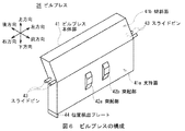
ビルプレス26は、図6に示すように、くの字状の板状部材でなるビルプレス本体部41におけるガイド部25と対向する面のうちの下方側の平坦な支持面41aのピックアップローラ22(22a、22b)と対向する位置に略台形柱の突起部42(42a、42b)が設けられる。 As shown in FIG. 6, the bill press 26 is a pickup roller 22 on a flat support surface 41 a on the lower side of the surface facing the guide portion 25 in the bill press main body portion 41 formed of a U-shaped plate-like member. Protrusions 42 (42a, 42b) having substantially trapezoidal pillars are provided at positions facing (22a, 22b).
またビルプレス26は、ビルプレス本体部41の長手方向(左右方向)の両端に、それぞれ2個ずつ前後方向に沿ってスライドピン43が設けられる。
The bill press 26 is provided with two
ビルプレス26は、図7に示すように、入出金部12のフレーム(図示せず)に設けられるスライド溝51にスライドピン43が嵌め込まれることで、該スライド溝51に沿って移動可能に支持される。
As shown in FIG. 7, the bill press 26 is supported so as to be movable along the
スライド溝51は、前後方向に延びる前方部51aと、該前方部51aより1段高い後方部51bと、前方部51a及び後方部51bの間を結ぶ傾斜する曲折部51cとにより形成される。
The
曲折部51cは、ビルプレス26が後方に移動して曲折部51cにスライドピン43が入り込んだ際にビルプレス本体部41の支持面41aがガイド25の当接面32aと平行な状態(図3)から集積舌片ローラ27側に傾斜し、かつビルプレス本体部41におけるガイド部25と対向する面のうちの上方側の傾斜面41bがガイド部25の当接面32aと平行な状態(図4)となるように、ビルプレス26を傾かせる傾斜角に設定される。
In the bent portion 51c, when the bill press 26 moves rearward and the
なお、ビルプレス26は、ビルプレス本体部41の長手方向における一端の下方に位置検出プレート44が設けられ、例えば光学式のポジションセンサ(図示せず)により位置検出プレート44の位置に基づいてその位置が検出される。 Incidentally, Bill press 26, longitudinal position detector below the one end of the plate 4 4 is provided for building press body portion 41, based on the position detection plate 4 4 position, for example by an optical position sensor (not shown) The position is detected.
集積舌片ローラ27は、複数の舌片を有する舌片車であり、収納庫11、一時保留部14又はリジェクト庫15に収納された紙幣BLが搬送路16を介して入出金部12に搬送される際に、該紙幣BLの後端を叩いてガイド部25側へ移動させる。
The accumulation tongue piece roller 27 is a tongue-and-crumb car having a plurality of tongue pieces, and the bills BL stored in the storage 11, the
[1−3.入出金部の動作]
入出金部12は、収納庫11等に収納された紙幣BLを顧客に支払う際、主制御部10の制御に応じて各部が動作する。具体的には入出金部12では、ビルプレス26が集積舌片ローラ27の上方に移動され、ガイド部25がビルプレス26から所定の間隔離間した位置に移動される。
[1-3. Operation of deposit / withdrawal department]
When the banknote BL stored in the storage 11 or the like is paid to the customer, the deposit / withdrawal unit 12 operates according to the control of the
そして入出金部12では、集積舌片ローラ27が回転され、搬送路16から搬送された紙幣BLが集積舌片ローラ27に叩かれて収容空間内にガイド部25に沿って集積される。入出金部12では、全ての紙幣BLが集積すると、ビルプレス26がガイド部25側に移動され、ガイド部25とビルプレス26とにより紙幣BLを挟持する。 In the deposit / withdrawal unit 12, the accumulation tongue piece roller 27 is rotated, and the bills BL conveyed from the conveyance path 16 are struck by the accumulation tongue piece roller 27 and accumulated in the accommodation space along the guide portion 25. In the deposit / withdrawal unit 12, when all the bills BL are accumulated, the bill press 26 is moved to the guide unit 25 side, and the bills BL are sandwiched between the guide unit 25 and the bill press 26.
その後、入出金部12では、紙幣BLを挟持した状態でガイド部25及びビルプレス26がピックアップローラ22側に移動された後、シャッタ21が開放して顧客に紙幣BLを支払う。このとき、予めビルプレス26の停止位置を定めており、その停止位置までビルプレス26を移動させると共に、それに応じてガイド部25も移動させる。 Thereafter, in the deposit / withdrawal unit 12, after the guide unit 25 and the bill press 26 are moved to the pickup roller 22 side with the bill BL being held, the shutter 21 is opened and the bill BL is paid to the customer. At this time, the stop position of the bill press 26 is determined in advance, and the bill press 26 is moved to the stop position, and the guide portion 25 is also moved accordingly.
一方、入出金部12は、顧客から紙幣BLが投入される際、主制御部10の制御に応じて各部が動作する。具体的には入出金部12では、ガイド部25及びビルプレス26が紙幣入出金口4の開口よりも狭くかつ顧客の手が入る程度の収容空間となるように移動された後、シャッタ21が開かれる。
On the other hand, each part of the deposit / withdrawal unit 12 operates according to the control of the
そして入出金部12では、顧客により紙幣入出金口4から紙幣BLが収容空間に投入されると、シャッタ21が閉じられた後、ビルプレス26がガイド部25側に移動され、ガイド部25とビルプレス26とによって投入された紙幣BLを立位の状態で挟持する。 In the deposit / withdrawal unit 12, when the bill BL is inserted into the accommodation space from the bill deposit / withdrawal port 4 by the customer, the bill press 26 is moved to the guide unit 25 side after the shutter 21 is closed. The bill BL inserted by the bill press 26 is held in a standing state.
入出金部12では、紙幣BLを挟持した状態でガイド部25及びビルプレス26がピックアップローラ22側に移動され、ピックアップローラ22がガイド部25のピックアップローラ孔33から収容空間内に突出して紙幣BLに当接する(図3)。 In the deposit / withdrawal unit 12, the guide unit 25 and the bill press 26 are moved to the pickup roller 22 side in a state where the bill BL is sandwiched, and the pickup roller 22 protrudes from the pickup roller hole 33 of the guide unit 25 into the accommodation space to protrude the bill BL. (Fig. 3).
その後、入出金部12では、ピックアップローラ22及びフィードローラ23が紙幣BLを繰り出す方向に回転し、ピックアップローラ22に当接している紙幣BLが1枚ずつに分離されて搬送路16に繰り出される。 Thereafter, in the deposit / withdrawal unit 12, the pickup roller 22 and the feed roller 23 rotate in the direction in which the bills BL are fed out, and the bills BL in contact with the pickup roller 22 are separated one by one and fed out to the conveyance path 16.
ところで、図8に示すような紙幣BLの長手方向に厚さが異なる紙幣束BLWが入出金部12に投入される場合が考えられる。因みに、長手方向に厚さが異なる要因としては、紙幣BLの長手方向における一端側に短手方向に沿ってセキュリティスレッドが入れられている等がある。 By the way, the case where the banknote bundle BLW from which thickness differs in the longitudinal direction of the banknote BL as shown in FIG. Incidentally, as a factor in which the thickness differs in the longitudinal direction, there is a security thread inserted along the short direction on one end side in the longitudinal direction of the bill BL.
入出金部12は、図9に示すように、紙幣BLの長手方向に厚さが異なる紙幣束BLWが入出金部12に投入された場合でも、ピックアップローラ22及び突起部42により該紙幣束BLWを挟持する。 As shown in FIG. 9, the deposit / withdrawal unit 12 has the bill bundle BLW by the pickup roller 22 and the protrusion 42 even when a bill bundle BLW having a thickness different from the longitudinal direction of the bill BL is inserted into the deposit / withdrawal unit 12. Pinch.
よって入出金部12では、紙幣束BLWをビルプレス26の支持面41aから離間して該紙幣束BLWの中央部を挟持するので、紙幣BLにおける紙幣束BLWが厚い方の端部がガイド部25に密着することを減少させることができる。 Therefore, since the banknote bundle BLW is separated from the support surface 41a of the bill press 26 and the central part of the banknote bundle BLW is sandwiched in the deposit / withdrawal section 12, the end of the banknote BL in which the banknote bundle BLW is thicker is the guide section 25. It is possible to reduce sticking to.
これにより入出金部12は、紙幣BLの長手方向に厚さが異なる紙幣束BLWが入出金部12に投入された場合においても、紙幣BLを繰り出す際にガイド部25と紙幣BLの一方の端部との摩擦抵抗によるスキューを従来と比して減少させることができる。 Thereby, even when the banknote bundle BLW having different thicknesses in the longitudinal direction of the banknote BL is inserted into the banknote depositing / dispensing section 12, the depositing / dispensing section 12 can be used when feeding the banknote BL to one end of the guide section 25 and the banknote BL. Skew due to frictional resistance with the part can be reduced as compared with the conventional case.
また入出金部12は、ガイド部25に低摩擦部材32が設けられているので、例えば紙幣BLとガイド本体部31との摩擦係数が高い場合や、シワが多くある紙幣BLが多くある紙幣束BLWを挟持する際に、紙幣BLがガイド部25と接触しても、低摩擦部材32に紙幣BLが接触する。 Moreover, since the deposit / withdrawal part 12 is provided with the low friction member 32 in the guide part 25, for example, when the friction coefficient between the banknote BL and the guide main body part 31 is high, or the banknote bundle with many wrinkles banknotes BL. Even when the bill BL comes into contact with the guide portion 25 when the BLW is sandwiched, the bill BL comes into contact with the low friction member 32.
これにより入出金部12は、紙幣BLがガイド部25と接触しても摩擦抵抗を減少させることができ、かくして紙幣BLを繰り出す際のスキューを従来と比して減少させることができる。 Thereby, even if the banknote BL contacts the guide part 25, the depositing / withdrawing part 12 can reduce frictional resistance, and can reduce the skew at the time of paying out banknote BL compared with the past.
またガイド部25は、ガイド本体部31より低摩擦部材32が後方に出っ張るように密着されているので、ガイド本体部31に接触することをより防止することができる。 Moreover, since the guide part 25 is closely_contact | adhered so that the low friction member 32 protrudes back rather than the guide main body part 31, it can prevent contacting the guide main body part 31 more.
〈2.他の実施の形態〉
[2−1.他の実施の形態1]
上述した実施の形態においては、ビルプレス26の支持面41aにおけるピックアップローラ22と対向する位置に略台形柱の突起部42がそれぞれ設けられるようにした場合について述べた。本発明はこれに限らず、ビルプレスの支持面におけるピックアップローラ22と対向する位置に、支持面から突起した突起部が設けられるようにすれば、その形状は問わない。
<2. Other Embodiments>
[2-1. Other Embodiment 1]
In the above-described embodiment, the case has been described in which the substantially trapezoidal columnar protrusions 42 are respectively provided at positions facing the pickup roller 22 on the support surface 41a of the bill press 26. The present invention is not limited to this, and any shape can be used as long as a protruding portion protruding from the support surface is provided at a position facing the pickup roller 22 on the support surface of the bill press.
例えば、図10に示すように、ビルプレス126は、ビルプレス本体部141の支持面141aにおけるピックアップローラ22とそれぞれ対向する位置に、上下方向にスリットを有する突起部142(142a、142b)が設けられる。ビルプレス126は、紙幣BLを繰り出す際の摩擦抵抗をビルプレス26より低減することができる。 For example, as shown in FIG. 10, the bill press 126 is provided with protrusions 142 (142a, 142b) having slits in the vertical direction at positions facing the pickup roller 22 on the support surface 141a of the bill press main body 141, respectively. It is done. The bill press 126 can reduce the frictional resistance when paying out the bills BL more than the bill press 26.
また図11に示すように、ビルプレス226は、ビルプレス本体部241の支持面241aにおけるピックアップローラ22と対向する中央部に突起部242が設けられる。 Further, as shown in FIG. 11, the bill press 226 is provided with a protrusion 242 at a central portion of the support surface 241 a of the bill press main body 241 facing the pickup roller 22.
なお、ビルプレス126及び226は、突起部142及び242の形状以外はビルプレス26と同様の構成である。 The bill presses 126 and 226 have the same configuration as the bill press 26 except for the shapes of the protrusions 142 and 242.
[2−2.他の実施の形態2]
上述した実施の形態においては、ガイド部25は、ガイド本体部31の中央部に低摩擦部材32が密着されるようにした場合について述べた。本発明はこれに限らない。例えば、図12に示すように、ガイド部125は、ガイド本体部131における傾斜部に低摩擦部材132(132a、132b)が密着されるようにしてもよい。なおガイド部125は、ピックアップローラ22に対応する位置にピックアップローラ孔133及び134が設けられる。
[2-2. Other Embodiment 2]
In the above-described embodiment, the guide portion 25 has been described with respect to the case where the low friction member 32 is in close contact with the central portion of the guide main body portion 31. The present invention is not limited to this. For example, as illustrated in FIG. 12, the guide portion 125 may be configured such that the low friction member 132 (132a, 132b) is in close contact with an inclined portion of the guide main body portion 131. The guide portion 125 is provided with pickup roller holes 133 and 134 at positions corresponding to the pickup roller 22.
またガイド部は、ガイド本体部の中央部及び傾斜部に低摩擦部材が密着されるようにしてもよい。 Further, the guide portion may be configured such that the low friction member is in close contact with the central portion and the inclined portion of the guide main body portion.
[2−3.他の実施の形態3]
上述した実施の形態においては、ピックアップローラ22が左右方向に並んで2つ配置され、該ピックアップローラ22と対抗する位置に突起部42がそれぞれ設けられるようにした場合について述べた。本発明はこれに限らず、ピックアップローラ22が左右方向に並んで2つ以上配置され、該ピックアップローラ22と対向する位置に突起部42がそれぞれ設けられるようにしてもよい。
[2-3. Other Embodiment 3]
In the above-described embodiment, a case has been described in which two pickup rollers 22 are arranged side by side in the left-right direction, and the protrusions 42 are provided at positions opposed to the pickup roller 22, respectively. The present invention is not limited to this, and two or more pickup rollers 22 may be arranged in the left-right direction, and the protrusions 42 may be provided at positions facing the pickup rollers 22.
[2−4.他の実施の形態4]
上述した実施の形態においては、ガイド部及びビルプレスを入出金部に適応した場合について述べたが、本発明はこれに限らず、紙葉類を収容するような、例えば収納庫、リジェクト庫等にも上述したガイド部及びビルプレスを適応することができる。
[2-4. Other Embodiment 4]
In the above-described embodiment, the case where the guide unit and the bill press are applied to the deposit / withdrawal unit has been described. However, the present invention is not limited to this, and stores paper sheets, for example, a storage, a reject storage, etc. Also, the above-described guide portion and bill press can be applied.
本発明は、紙幣等の紙葉類を搬送する自動取引装置や、コピー機、自動販売機、券売機などの装置で広く利用することができる。 The present invention can be widely used in apparatuses such as an automatic transaction apparatus that conveys paper sheets such as banknotes, a copying machine, a vending machine, and a ticket vending machine.
1……自動取引装置、12……入出金部、21……シャッタ、22……ピックアップローラ、23……フィードローラ、24……ゲートローラ、25……ガイド部、26……ビルプレス、27……集積舌片ローラ、31……ガイド本体部、32……低摩擦部材、33……ピックアップローラ孔、41……ビルプレス本体部、42……突起部、43……スライドピン、44……位置検出プレート。 DESCRIPTION OF SYMBOLS 1 ... Automatic transaction apparatus, 12 ... Deposit / withdrawal part, 21 ... Shutter, 22 ... Pickup roller, 23 ... Feed roller, 24 ... Gate roller, 25 ... Guide part, 26 ... Bill press, 27 …… Integrated tongue roller, 31 …… Guide body, 32 …… Low friction member, 33 …… Pickup roller hole, 41 …… Bill press body, 42 …… Protrusion, 43 …… Slide pin, 44… ... position detection plate.
Claims (6)
前記収容空間における一面を形成し、前記ピックアップローラの一部が収容空間に突出するための孔を有するガイド部と、
前記ガイド部と対向して配置されて前記収容空間の一面を形成し、前記ガイド部と対向する支持面における前記ピックアップローラと対向する位置に、前記収容空間側に突起する突起部を有するビルプレスと
を有し、
前記ビルプレスは、前記支持面と、該支持面から前記紙葉類を繰り出す方向とは逆方向に向かって傾斜した傾斜面とにより略くの字状に形成され、
前記ピックアップローラは、前記紙葉類を繰り出す方向に対して直交する方向に2以上配置され、
前記突起部は、前記ビルプレスの前記支持面における、前記2以上のピックアップローラの全てに対向する位置に1つ配置され、
さらに前記突起部は、前記ピックアップローラに対向する対向面と、該対向面から前記支持面に向かって傾斜した傾斜面とにより略台形状に形成され、
さらに、顧客に対して前記紙葉類を渡す際は、前記ビルプレスの傾斜面が前記ガイド部と対向するように前記ビルプレスを傾斜させ、顧客により前記収容空間内に投入された前記紙葉類を繰り出す際は、前記ビルプレスの支持面が前記ガイド部と対向するように前記ビルプレスを傾斜させる傾斜手段を備え、
顧客により前記収容空間内に投入された前記紙葉類を繰り出す際、前記ピックアップローラ及び前記突起部により該紙葉類を挟持する
自動取引装置。 A pick-up roller for feeding out paper sheets in a storage space in which paper sheets are stored;
A guide portion that forms a surface in the housing space and has a hole for a part of the pickup roller to protrude into the housing space;
A bill press that is disposed to face the guide portion to form one surface of the housing space, and has a projection that projects toward the housing space at a position facing the pickup roller on a support surface facing the guide portion. And
The bill press is formed in a substantially U shape by the support surface and an inclined surface inclined in a direction opposite to a direction in which the paper sheet is fed out from the support surface,
Two or more pickup rollers are arranged in a direction perpendicular to the direction of feeding out the paper sheets,
One of the protrusions is disposed at a position facing all of the two or more pickup rollers on the support surface of the bill press,
Further, the protrusion is formed in a substantially trapezoidal shape by an opposing surface facing the pickup roller and an inclined surface inclined from the opposing surface toward the support surface,
Further, when handing over the paper sheets to the customer, the bill press is inclined so that the inclined surface of the bill press faces the guide portion, and the paper sheet is put into the accommodation space by the customer. When paying out, a tilting means for tilting the bill press so that a support surface of the bill press faces the guide portion,
An automatic transaction apparatus that clamps the paper sheet by the pickup roller and the protrusion when the paper sheet put into the accommodation space by the customer is fed out.
前記ビルプレスと対向する面を有する本体部と、
前記本体部における前記ビルプレスと対向する面に配置され、前記本体部よりも摩擦係数が小さい低摩擦部材とを有する
請求項1に記載の自動取引装置。 The guide portion is
A main body having a surface facing the bill press;
The automatic transaction apparatus according to claim 1, further comprising: a low friction member disposed on a surface of the main body portion facing the bill press and having a smaller friction coefficient than the main body portion.
請求項2に記載の自動取引装置。 The automatic transaction apparatus according to claim 2 , wherein the protrusion is provided with a plurality of slits in a direction orthogonal to a direction in which the paper sheet is fed out.
前記ビルプレスと対向する面の中央部が該ビルプレスにおける前記収容空間を形成する面と平行し、該中央部から左右に向けて該ビルプレスに対して離間するように傾斜した傾斜部を有し、
前記低摩擦部材は、前記本体部における前記中央部に設けられる
請求項2に記載の自動取引装置。 The main body is
A central portion of a surface facing the bill press is parallel to a surface forming the accommodation space in the bill press, and has an inclined portion inclined so as to be separated from the bill press from the central portion toward the left and right. And
The automatic transaction apparatus according to claim 2, wherein the low friction member is provided in the central portion of the main body portion.
前記ビルプレスと対向する面の中央部が該ビルプレスにおける前記収容空間を形成する面と平行し、該中央部から左右に向けて該ビルプレスに対して離間するように傾斜した傾斜部を有し、
前記低摩擦部材は、前記本体部における前記傾斜部に設けられる
請求項2に記載の自動取引装置。 The main body is
A central portion of a surface facing the bill press is parallel to a surface forming the accommodation space in the bill press, and has an inclined portion inclined so as to be separated from the bill press from the central portion toward the left and right. And
The automatic transaction apparatus according to claim 2, wherein the low friction member is provided in the inclined portion of the main body portion.
前記収容空間における一面を形成し、前記ピックアップローラの一部が収容空間に突出するための孔を有するガイド部と、
前記ガイド部と対向して配置されて前記収容空間の一面を形成する突起部を有するビルプレスと
を有し、
前記ビルプレスは、前記ガイド部と対向する支持面と、該支持面から前記紙葉類を繰り出す方向とは逆方向に向かって傾斜した傾斜面とにより略くの字状に形成され、
前記ピックアップローラは、前記紙葉類を繰り出す方向に対して直交する方向に2以上配置され、
前記突起部は、前記ビルプレスの前記支持面における、前記2以上のピックアップローラの全てに対向する位置に1つ配置され、
さらに前記突起部は、前記ピックアップローラに対向する対向面と、該対向面から前記支持面に向かって傾斜した傾斜面とにより略台形状に形成され、
さらに、顧客に対して前記紙葉類を渡す際は、前記ビルプレスの傾斜面が前記ガイド部と対向するように前記ビルプレスを傾斜させ、顧客により前記収容空間内に投入された前記紙葉類を繰り出す際は、前記ビルプレスの支持面が前記ガイド部と対向するように前記ビルプレスを傾斜させる傾斜手段を備え、
前記ガイド部は、
前記ビルプレスと対向する面を有する本体部と、
前記本体部における前記ビルプレスと対向する面に配置され、前記本体部よりも摩擦係数が小さい低摩擦部材とを有し、
顧客により前記収容空間内に投入された前記紙葉類を繰り出す際、前記ピックアップローラ及び前記突起部により該紙葉類を挟持する
自動取引装置。 A pickup roller for feeding out the paper sheets in a storage space in which the paper sheets are stored;
A guide portion that forms a surface in the housing space and has a hole for a part of the pickup roller to protrude into the housing space;
A bill press having a protrusion disposed opposite to the guide portion and forming one surface of the accommodation space;
The bill press is formed in a substantially U shape by a support surface facing the guide portion and an inclined surface inclined in a direction opposite to a direction in which the paper sheet is fed out from the support surface,
Two or more pickup rollers are arranged in a direction perpendicular to the direction of feeding out the paper sheets,
One of the protrusions is disposed at a position facing all of the two or more pickup rollers on the support surface of the bill press,
Further, the protrusion is formed in a substantially trapezoidal shape by an opposing surface facing the pickup roller and an inclined surface inclined from the opposing surface toward the support surface,
Further, when handing over the paper sheets to the customer, the bill press is inclined so that the inclined surface of the bill press faces the guide portion, and the paper sheet is put into the accommodation space by the customer. When paying out, a tilting means for tilting the bill press so that a support surface of the bill press faces the guide portion,
The guide portion is
A main body having a surface facing the bill press;
A low friction member disposed on a surface of the main body portion facing the bill press and having a smaller coefficient of friction than the main body portion;
An automatic transaction apparatus that clamps the paper sheet by the pickup roller and the protrusion when the paper sheet put into the accommodation space by the customer is fed out.
Priority Applications (3)
| Application Number | Priority Date | Filing Date | Title |
|---|---|---|---|
| JP2012287863A JP6064597B2 (en) | 2012-12-28 | 2012-12-28 | Automatic transaction equipment |
| CN201380064220.4A CN104854628B (en) | 2012-12-28 | 2013-11-08 | Automatic transaction device |
| PCT/JP2013/080320 WO2014103531A1 (en) | 2012-12-28 | 2013-11-08 | Automatic transaction device |
Applications Claiming Priority (1)
| Application Number | Priority Date | Filing Date | Title |
|---|---|---|---|
| JP2012287863A JP6064597B2 (en) | 2012-12-28 | 2012-12-28 | Automatic transaction equipment |
Publications (3)
| Publication Number | Publication Date |
|---|---|
| JP2014130479A JP2014130479A (en) | 2014-07-10 |
| JP2014130479A5 JP2014130479A5 (en) | 2015-10-01 |
| JP6064597B2 true JP6064597B2 (en) | 2017-01-25 |
Family
ID=51020630
Family Applications (1)
| Application Number | Title | Priority Date | Filing Date |
|---|---|---|---|
| JP2012287863A Active JP6064597B2 (en) | 2012-12-28 | 2012-12-28 | Automatic transaction equipment |
Country Status (3)
| Country | Link |
|---|---|
| JP (1) | JP6064597B2 (en) |
| CN (1) | CN104854628B (en) |
| WO (1) | WO2014103531A1 (en) |
Families Citing this family (5)
| Publication number | Priority date | Publication date | Assignee | Title |
|---|---|---|---|---|
| CN104077838B (en) * | 2014-07-23 | 2016-05-11 | 广州广电运通金融电子股份有限公司 | A kind of linkage |
| CN106204911A (en) * | 2016-08-05 | 2016-12-07 | 深圳怡化电脑股份有限公司 | paper money temporary storage device and paper money automatic trading device |
| JP2018132872A (en) * | 2017-02-14 | 2018-08-23 | 沖電気工業株式会社 | Cash processing device |
| JP6850685B2 (en) * | 2017-06-02 | 2021-03-31 | 日本金銭機械株式会社 | Paper leaf loading device and load adjustment method |
| WO2024176282A1 (en) * | 2023-02-20 | 2024-08-29 | 富士通フロンテック株式会社 | Paper sheet handling device |
Family Cites Families (6)
| Publication number | Priority date | Publication date | Assignee | Title |
|---|---|---|---|---|
| JPS631652A (en) * | 1986-06-23 | 1988-01-06 | Shigetaro Muraoka | Card driving-out mechanism |
| JPS63189332A (en) * | 1987-02-03 | 1988-08-04 | Fujitsu Ltd | Roller cover mechanism |
| JP2634928B2 (en) * | 1990-06-07 | 1997-07-30 | 甲府日本電気株式会社 | Paper feeding mechanism |
| JP3560223B2 (en) * | 1998-09-17 | 2004-09-02 | 株式会社日立製作所 | Paper sheet separation and feeding device |
| JP5292761B2 (en) * | 2007-10-16 | 2013-09-18 | 沖電気工業株式会社 | Bill separation and accumulation mechanism |
| JP4808765B2 (en) * | 2008-12-25 | 2011-11-02 | 日立オムロンターミナルソリューションズ株式会社 | Bill separation mechanism |
-
2012
- 2012-12-28 JP JP2012287863A patent/JP6064597B2/en active Active
-
2013
- 2013-11-08 WO PCT/JP2013/080320 patent/WO2014103531A1/en active Application Filing
- 2013-11-08 CN CN201380064220.4A patent/CN104854628B/en active Active
Also Published As
| Publication number | Publication date |
|---|---|
| JP2014130479A (en) | 2014-07-10 |
| CN104854628A (en) | 2015-08-19 |
| WO2014103531A1 (en) | 2014-07-03 |
| CN104854628B (en) | 2017-05-17 |
Similar Documents
| Publication | Publication Date | Title |
|---|---|---|
| JP5292761B2 (en) | Bill separation and accumulation mechanism | |
| TWI354949B (en) | ||
| JP5564915B2 (en) | Banknote deposit and withdrawal machine | |
| JP5332512B2 (en) | Banknote deposit / withdrawal mechanism | |
| KR101413893B1 (en) | Paper money deposit/withdrawal machine | |
| JP5831321B2 (en) | Medium storing and feeding apparatus and medium transaction apparatus | |
| EP2043059A2 (en) | Paper sheet storing apparatus, paper sheet handling system, and automatic teller machine | |
| JP6064597B2 (en) | Automatic transaction equipment | |
| JP6369114B2 (en) | Identification device and medium transaction device | |
| JP6052059B2 (en) | Medium stacking apparatus and medium processing apparatus | |
| JP2014047073A (en) | Thickness detector and medium transaction device | |
| JP6146229B2 (en) | Medium transport apparatus and medium transaction apparatus | |
| WO2016059839A1 (en) | Medium accommodating device and medium transaction device | |
| JP6064791B2 (en) | Medium feeding apparatus and medium processing apparatus | |
| JP2014219901A (en) | Medium accommodation device and medium transaction device | |
| JP6593150B2 (en) | Medium discrimination device and automatic transaction device | |
| WO2015040901A1 (en) | Medium dispensing device and medium transaction device | |
| JP7052470B2 (en) | Media processing equipment and media trading equipment | |
| JPS5943739A (en) | Magazine for paper sheets | |
| JP7226098B2 (en) | Media processing device and media trading device | |
| JP2019133351A (en) | Medium processor and automatic transaction device | |
| JP6478442B2 (en) | Medium stacking apparatus and medium processing apparatus | |
| JP6866806B2 (en) | Media processing equipment and automated teller machines | |
| JP6834472B2 (en) | Media separator, media storage and media trading equipment | |
| JP5807581B2 (en) | Media collection box and media transaction device |
Legal Events
| Date | Code | Title | Description |
|---|---|---|---|
| A521 | Written amendment |
Free format text: JAPANESE INTERMEDIATE CODE: A523 Effective date: 20150817 |
|
| A621 | Written request for application examination |
Free format text: JAPANESE INTERMEDIATE CODE: A621 Effective date: 20150817 |
|
| A131 | Notification of reasons for refusal |
Free format text: JAPANESE INTERMEDIATE CODE: A131 Effective date: 20160621 |
|
| A521 | Written amendment |
Free format text: JAPANESE INTERMEDIATE CODE: A523 Effective date: 20160815 |
|
| A131 | Notification of reasons for refusal |
Free format text: JAPANESE INTERMEDIATE CODE: A131 Effective date: 20160906 |
|
| A521 | Written amendment |
Free format text: JAPANESE INTERMEDIATE CODE: A523 Effective date: 20161104 |
|
| TRDD | Decision of grant or rejection written | ||
| A01 | Written decision to grant a patent or to grant a registration (utility model) |
Free format text: JAPANESE INTERMEDIATE CODE: A01 Effective date: 20161122 |
|
| A61 | First payment of annual fees (during grant procedure) |
Free format text: JAPANESE INTERMEDIATE CODE: A61 Effective date: 20161205 |
|
| R150 | Certificate of patent or registration of utility model |
Ref document number: 6064597 Country of ref document: JP Free format text: JAPANESE INTERMEDIATE CODE: R150 |