JP6064256B2 - Electronic equipment and cushioning materials - Google Patents

Electronic equipment and cushioning materials Download PDF

Info

Publication number
JP6064256B2
JP6064256B2 JP2013027651A JP2013027651A JP6064256B2 JP 6064256 B2 JP6064256 B2 JP 6064256B2 JP 2013027651 A JP2013027651 A JP 2013027651A JP 2013027651 A JP2013027651 A JP 2013027651A JP 6064256 B2 JP6064256 B2 JP 6064256B2
Authority
JP
Japan
Prior art keywords
cushioning material
hdd
buckling
buffer
impact
Prior art date
Legal status (The legal status is an assumption and is not a legal conclusion. Google has not performed a legal analysis and makes no representation as to the accuracy of the status listed.)
Active
Application number
JP2013027651A
Other languages
Japanese (ja)
Other versions
JP2014063469A (en
JP2014063469A5 (en
Inventor
彰 岩本
彰 岩本
仁之 中谷
仁之 中谷
森 猛
猛 森
俊 島崎
俊 島崎
孝裕 田端
孝裕 田端
Current Assignee (The listed assignees may be inaccurate. Google has not performed a legal analysis and makes no representation or warranty as to the accuracy of the list.)
Panasonic Intellectual Property Management Co Ltd
Original Assignee
Panasonic Intellectual Property Management Co Ltd
Priority date (The priority date is an assumption and is not a legal conclusion. Google has not performed a legal analysis and makes no representation as to the accuracy of the date listed.)
Filing date
Publication date
Application filed by Panasonic Intellectual Property Management Co Ltd filed Critical Panasonic Intellectual Property Management Co Ltd
Priority to JP2013027651A priority Critical patent/JP6064256B2/en
Publication of JP2014063469A publication Critical patent/JP2014063469A/en
Publication of JP2014063469A5 publication Critical patent/JP2014063469A5/ja
Application granted granted Critical
Publication of JP6064256B2 publication Critical patent/JP6064256B2/en
Active legal-status Critical Current
Anticipated expiration legal-status Critical

Links

Images

Classifications

    • GPHYSICS
    • G11INFORMATION STORAGE
    • G11BINFORMATION STORAGE BASED ON RELATIVE MOVEMENT BETWEEN RECORD CARRIER AND TRANSDUCER
    • G11B33/00Constructional parts, details or accessories not provided for in the other groups of this subclass
    • G11B33/02Cabinets; Cases; Stands; Disposition of apparatus therein or thereon
    • G11B33/08Insulation or absorption of undesired vibrations or sounds
    • FMECHANICAL ENGINEERING; LIGHTING; HEATING; WEAPONS; BLASTING
    • F16ENGINEERING ELEMENTS AND UNITS; GENERAL MEASURES FOR PRODUCING AND MAINTAINING EFFECTIVE FUNCTIONING OF MACHINES OR INSTALLATIONS; THERMAL INSULATION IN GENERAL
    • F16FSPRINGS; SHOCK-ABSORBERS; MEANS FOR DAMPING VIBRATION
    • F16F13/00Units comprising springs of the non-fluid type as well as vibration-dampers, shock-absorbers, or fluid springs
    • F16F13/04Units comprising springs of the non-fluid type as well as vibration-dampers, shock-absorbers, or fluid springs comprising both a plastics spring and a damper, e.g. a friction damper
    • FMECHANICAL ENGINEERING; LIGHTING; HEATING; WEAPONS; BLASTING
    • F16ENGINEERING ELEMENTS AND UNITS; GENERAL MEASURES FOR PRODUCING AND MAINTAINING EFFECTIVE FUNCTIONING OF MACHINES OR INSTALLATIONS; THERMAL INSULATION IN GENERAL
    • F16FSPRINGS; SHOCK-ABSORBERS; MEANS FOR DAMPING VIBRATION
    • F16F15/00Suppression of vibrations in systems; Means or arrangements for avoiding or reducing out-of-balance forces, e.g. due to motion
    • F16F15/02Suppression of vibrations of non-rotating, e.g. reciprocating systems; Suppression of vibrations of rotating systems by use of members not moving with the rotating systems
    • F16F15/04Suppression of vibrations of non-rotating, e.g. reciprocating systems; Suppression of vibrations of rotating systems by use of members not moving with the rotating systems using elastic means
    • F16F15/08Suppression of vibrations of non-rotating, e.g. reciprocating systems; Suppression of vibrations of rotating systems by use of members not moving with the rotating systems using elastic means with rubber springs ; with springs made of rubber and metal
    • FMECHANICAL ENGINEERING; LIGHTING; HEATING; WEAPONS; BLASTING
    • F16ENGINEERING ELEMENTS AND UNITS; GENERAL MEASURES FOR PRODUCING AND MAINTAINING EFFECTIVE FUNCTIONING OF MACHINES OR INSTALLATIONS; THERMAL INSULATION IN GENERAL
    • F16FSPRINGS; SHOCK-ABSORBERS; MEANS FOR DAMPING VIBRATION
    • F16F3/00Spring units consisting of several springs, e.g. for obtaining a desired spring characteristic
    • F16F3/08Spring units consisting of several springs, e.g. for obtaining a desired spring characteristic with springs made of a material having high internal friction, e.g. rubber
    • F16F3/087Units comprising several springs made of plastics or the like material
    • F16F3/093Units comprising several springs made of plastics or the like material the springs being of different materials, e.g. having different types of rubber
    • FMECHANICAL ENGINEERING; LIGHTING; HEATING; WEAPONS; BLASTING
    • F16ENGINEERING ELEMENTS AND UNITS; GENERAL MEASURES FOR PRODUCING AND MAINTAINING EFFECTIVE FUNCTIONING OF MACHINES OR INSTALLATIONS; THERMAL INSULATION IN GENERAL
    • F16FSPRINGS; SHOCK-ABSORBERS; MEANS FOR DAMPING VIBRATION
    • F16F2228/00Functional characteristics, e.g. variability, frequency-dependence
    • F16F2228/14Functional characteristics, e.g. variability, frequency-dependence progressive
    • FMECHANICAL ENGINEERING; LIGHTING; HEATING; WEAPONS; BLASTING
    • F16ENGINEERING ELEMENTS AND UNITS; GENERAL MEASURES FOR PRODUCING AND MAINTAINING EFFECTIVE FUNCTIONING OF MACHINES OR INSTALLATIONS; THERMAL INSULATION IN GENERAL
    • F16FSPRINGS; SHOCK-ABSORBERS; MEANS FOR DAMPING VIBRATION
    • F16F2230/00Purpose; Design features
    • F16F2230/0052Physically guiding or influencing
    • F16F2230/007Physically guiding or influencing with, or used as an end stop or buffer; Limiting excessive axial separation

Description

本開示は、緩衝材を介在した電子部品を搭載する電子機器と緩衝材に関する。   The present disclosure relates to an electronic device on which an electronic component with a cushioning material interposed therebetween and a cushioning material.

電子機器としては、例えば特許文献1に開示されているノートブック型パーソナルコンピュータがある。この特許文献1は、ノートブック型パーソナルコンピュータの筐体に設けられたディスク装置収納部を覆う蓋部材と、ディスク装置との間に、振動及び/又は衝撃を吸収する複数の小片からなる振動及び/又は衝撃吸収材、および、複数の小片からなる振動及び/又は衝撃吸収材とディスク装置との間に設けられたシート材を設ける構成を開示している。この上記構成の小片からなる振動及び/又は衝撃を吸収する特性が相異なる2種類の振動及び/又は衝撃吸収材を、ディスク装置の外周側に厚い肉厚を配置し内周側に薄い肉厚を配置する構成も開示している。   An example of the electronic apparatus is a notebook personal computer disclosed in Patent Document 1. This Patent Document 1 discloses a vibration and / or a plurality of small pieces that absorb vibration and / or impact between a lid member that covers a disk device housing provided in a casing of a notebook personal computer and a disk device. A configuration is disclosed in which a shock absorbing material and / or a sheet material provided between a vibration and / or shock absorbing material composed of a plurality of small pieces and a disk device are disclosed. Two types of vibration and / or shock absorbers having different characteristics for absorbing vibration and / or shock composed of small pieces having the above-described configuration are arranged with a thick wall on the outer peripheral side of the disk device and a thin wall on the inner peripheral side. The structure which arrange | positions is also disclosed.

特開2008−171554号公報JP 2008-171554 A

本開示は、第1の部品と第2の部品との間に働く荷重を吸収する際、挙動が異なる2種類の緩衝材を配置することで、振動および/または衝撃吸収性能を向上させる電子機器および緩衝材を提供する。   The present disclosure relates to an electronic device that improves vibration and / or shock absorption performance by arranging two types of cushioning materials having different behaviors when absorbing a load acting between a first component and a second component. And provide cushioning material.

本開示の電子機器は、第1の部品と、第1の部品の一部に隣接する第2の部品と、第1の部品と第2の部品との間に配置される緩衝部とを備え、緩衝部は、第1の部品と第2の部品との間に働く荷重に対して、荷重が所定の値を越えた際に一部が座屈を起こし、さらに座屈の後に元の形状への復元性を有する第1緩衝材と、第1の部品と第2の部品との間に働く荷重に対して、所定の値よりも軽い荷重に対して変形する第2緩衝材とを備え、第1緩衝材は、荷重が所定の値を越えた際に一部が座屈を起こす、中空の座屈部を有する構成である。 An electronic apparatus according to an embodiment of the present disclosure includes a first component, a second component adjacent to a part of the first component, and a buffer portion disposed between the first component and the second component. The buffer portion is partially buckled when the load exceeds a predetermined value with respect to the load acting between the first part and the second part, and further, the original shape after buckling. A first cushioning material having resilience to the first and a second cushioning material that deforms with respect to a load lighter than a predetermined value with respect to a load acting between the first component and the second component. the first buffer material is part when a load exceeds a predetermined value buckling occurs, a structure having a hollow buckling portion.

また、本開示の緩衝材は、荷重が所定の値を越えた際に一部が座屈を起こし、さらに座屈の後に元の形状への復元性を有する第1緩衝材と、第1緩衝材と同一方向の荷重であって所定の値よりも軽い荷重に対して変形する第2緩衝材と、第1緩衝材と第2緩衝材が配置される被接地面とを備え、第1緩衝材は、荷重が所定の値を越えた際に一部が座屈を起こす、中空の座屈部を有する構成である。 In addition, the cushioning material of the present disclosure is partially buckled when the load exceeds a predetermined value, and further has a first cushioning material having a restoring property to the original shape after buckling, and the first cushioning material. A second buffer material that is deformed with respect to a load that is in the same direction as the material and is lighter than a predetermined value, and a grounded surface on which the first buffer material and the second buffer material are disposed, wood is part when a load exceeds a predetermined value buckling occurs, a structure having a hollow buckling portion.

本開示の電子機器は、外部から加えられる振動および/または衝撃を幅広く緩和することができる。   The electronic device of the present disclosure can widely reduce vibration and / or shock applied from the outside.

ノート型パーソナルコンピュータ(PC)の外観斜視図である。1 is an external perspective view of a notebook personal computer (PC). PCに内蔵するハードディスクケースの分解斜視図である。It is a disassembled perspective view of the hard disk case built in PC. 1緩衝材および第2緩衝材を配置し、ハードディスクケースに収納したHDDの下面側平面図である。A first buffer material and the second buffer material disposed, is a bottom side plan view of the HDD accommodating the hard disk case. の分解側面図である。FIG. 4 is an exploded side view of FIG. 3 . 3に示したA−A線矢視方向の断面図である。It is sectional drawing of the AA arrow direction shown in FIG. 3に示したA−A線矢視方向の断面図である。It is sectional drawing of the AA arrow direction shown in FIG. 3に示したA−A線矢視方向の断面図である。It is sectional drawing of the AA arrow direction shown in FIG. 他の第1緩衝材および第2緩衝材をHDDに装着した状態における、図3に 示したA−A線矢視方向の断面図である。 FIG. 4 is a cross-sectional view taken along the line AA shown in FIG. 3 in a state in which another first buffer material and a second buffer material are mounted on the HDD. PCに内蔵する他のハードディスクケースの分解斜視図である。It is a disassembled perspective view of the other hard disk case built in PC. HDDとハードディスクケースとの位置関係の部分平面図である。It is a fragmentary top view of the positional relationship of HDD and a hard disk case. 他の第1緩衝材および第2緩衝材を配置し、ハードディスクケースに収納したHDDの下面側平面図である。It is the lower surface side top view of HDD which has arrange | positioned the other 1st shock absorbing material and the 2nd shock absorbing material, and accommodated in the hard disk case . の分解側面図である。FIG. 10 is an exploded side view of FIG. 9 . 9に示したA−A線矢視方向の断面図である。It is sectional drawing of the AA arrow direction shown in FIG. PCに内蔵する別のハードディスクケースの分解斜視図である。It is a disassembled perspective view of another hard disk case incorporated in PC. 他の第1緩衝材および第2緩衝材に押圧力が印加されていない状態の 分断面側面図である。It is a part partial cross-sectional side view illustrating a state where the pressing force is not applied to the other of the first buffer material and the second buffer material. 第1緩衝材に押圧力が印加されていない状態の部分断面側面図である。It is a partial section side view in the state where pressing force is not applied to the 1st buffer material. 第1緩衝材および第2緩衝材に押圧力を印加した状態の部分断面側面図である。It is a partial cross section side view in the state where pressing force was applied to the 1st shock absorbing material and the 2nd shock absorbing material. 別の第1緩衝材および第2緩衝材をHDDに装着した状態の平面図である。It is a top view in the state where another 1st shock absorbing material and 2nd shock absorbing material were mounted in HDD. 第1緩衝材および第2緩衝材に押圧力が印加されていない状態における 、図14に示したA−A線矢視方向の断面図である。It is sectional drawing of the AA arrow direction shown in FIG. 14 in the state in which the pressing force is not applied to the 1st shock absorbing material and the 2nd shock absorbing material. 第1緩衝材に押圧力が印加されていない状態における、図14に示した A−A線矢視方向の断面図である。It is sectional drawing of the AA arrow direction shown in FIG. 14 in the state in which the pressing force is not applied to the 1st buffer material. 第1緩衝材および第2緩衝材に押圧力を印加した状態における、図14 に示したA−A線矢視方向の断面図である。It is sectional drawing of the AA arrow direction shown in FIG. 14 in the state which applied the pressing force to the 1st shock absorbing material and the 2nd shock absorbing material. 別の第1緩衝材および第2緩衝材に押圧力が印加されていない状態にお ける、図14に示したA−A線矢視方向の断面図である。 Keru Contact state where the pressing force is not applied to another first buffer material and the second buffer material, a cross-sectional view of A-A direction indicated by the arrow shown in FIG. 14. 第1緩衝材および第2緩衝材に押圧力を印加した状態における、図14 に示したA−A線矢視方向の断面図である。It is sectional drawing of the AA arrow direction shown in FIG. 14 in the state which applied the pressing force to the 1st shock absorbing material and the 2nd shock absorbing material. 別の第1緩衝材および第2緩衝材に押圧力が印加されていない状態にお ける、図14に示したA−A線矢視方向の断面図である。 Keru Contact state where the pressing force is not applied to another first buffer material and the second buffer material, a cross-sectional view of A-A direction indicated by the arrow shown in FIG. 14. 第1緩衝材および第2緩衝材に押圧力を印加した状態における、図14 に示したA−A線矢視方向の断面図である。It is sectional drawing of the AA arrow direction shown in FIG. 14 in the state which applied the pressing force to the 1st shock absorbing material and the 2nd shock absorbing material. ハードディスクケースに収納したHDDの外観斜視図である。It is an external perspective view of HDD stored in a hard disk case . 第1緩衝材と第2緩衝材とをHDDに装着した部分断面側面図である。It is the partial cross section side view which mounted | wore with HDD the 1st shock absorbing material and the 2nd shock absorbing material. 第1緩衝材および第2緩衝材に押圧力が印加されていない状態の部分断 側面図である。It is a partial cross-sectional side view of a state where the pressing force is not applied to the first buffer material and the second buffer material. 第1緩衝材に押圧力が印加されていない状態の部分断面側面図である。It is a partial section side view in the state where pressing force is not applied to the 1st buffer material. 第1緩衝材および第2緩衝材に押圧力を印加した状態の部分断面側面図である。It is a partial cross section side view in the state where pressing force was applied to the 1st shock absorbing material and the 2nd shock absorbing material. 別の第1緩衝材と第2緩衝材とをHDDに装着した部分断面側面図である。It is the partial cross section side view which mounted another 1st shock absorbing material and 2nd shock absorbing material in HDD. 第1緩衝材および第2緩衝材に押圧力が印加されていない状態の部分断 側面図である。It is a partial cross-sectional side view of a state where the pressing force is not applied to the first buffer material and the second buffer material. 第1緩衝材に押圧力が印加されていない状態の部分断面側面図である。It is a partial section side view in the state where pressing force is not applied to the 1st buffer material. 第1緩衝材および第2緩衝材に押圧力を印加した状態部分断面の側面図である。It is a side view of the state partial section which applied pressing force to the 1st shock absorbing material and the 2nd shock absorbing material.

以下、図面を参照しながら、本開示の電子機器および緩衝材の一実施形態を挙げて説明する。なお、本実施形態では電子機器の一例としてノート型パーソナルコンピュータ(以下PCと略す)、第1の部品としてPCに内蔵するハードディスクドライブ(以下HDDと略す)を挙げる。但し、必要以上に詳細な説明は省略する場合がある。例えば、既によく知られた事項の詳細説明や実質的に同一の構成に対する重複説明を省略する場合がある。これは、以下の説明が不必要に冗長になるのを避け、当業者の理解を容易にするためである。   Hereinafter, an embodiment of an electronic device and a cushioning material according to the present disclosure will be described with reference to the drawings. In the present embodiment, a notebook personal computer (hereinafter abbreviated as “PC”) is exemplified as an example of an electronic device, and a hard disk drive (hereinafter abbreviated as “HDD”) built in the PC is exemplified as a first component. However, more detailed description than necessary may be omitted. For example, detailed descriptions of already well-known matters and repeated descriptions for substantially the same configuration may be omitted. This is to avoid the following description from becoming unnecessarily redundant and to facilitate understanding by those skilled in the art.

なお、発明者らは、当業者が本開示を十分に理解するために添付図面および以下の説明を提供するのであって、これらによって特許請求の範囲に記載の主題を限定することを意図するものではない。   In addition, the inventors provide the accompanying drawings and the following description in order for those skilled in the art to fully understand the present disclosure, and these are intended to limit the subject matter described in the claims. is not.

[PCの構成]
図1に示すPCは、操作筐体1と表示筐体2とを開閉可能に支持するヒンジ3を備え、表示筐体2は矢印A方向に回動させることで、表示筐体2を閉じた閉蓋状態に移行することができる。なお、図1は使用者がPCを操作する操作状態を示している。
[PC configuration]
The PC shown in FIG. 1 includes a hinge 3 that supports the operation housing 1 and the display housing 2 so that the operation housing 1 and the display housing 2 can be opened and closed. The display housing 2 is closed in the direction of arrow A by closing the display housing 2. It can shift to the closed state. FIG. 1 shows an operation state in which the user operates the PC.

操作筐体1は、キーボード4等を配置する表面1a、中央集積回路や各種電子部品を搭載した回路基板およびバッテリー等を内蔵する内部空間を介して表面1aと対向する裏面1b、PCが操作状態のとき操作者側に向く前面1c、操作状態のとき操作者の側の側面1dと側の側面1e、および上述のキーボード4を介して前面1cと対向する後面とを備える。また、表示筐体2は、操作者が視認する表示パネル2aを備える。 The operation housing 1 includes a front surface 1a on which a keyboard 4 and the like are disposed, a circuit board on which a central integrated circuit and various electronic components are mounted, and a back surface 1b that faces the front surface 1a through an internal space containing a battery and the like. comprising front 1c facing the operator's side, and a rear surface facing the front surface 1c through the right side 1d and the left side of the left side surface 1e of the right side of the operator when the operation state, and the above-mentioned keyboard 4 for. Further, the display housing 2 includes a display panel 2a that is visually recognized by the operator.

(実施の形態1)
[1−1.HDDの構成]
操作筐体1の内部空間には、中央集中回路、回路基板およびバッテリーのほかに、PCに授受する情報データ等を記憶するHDD7(後述)を収納する収納部を閉蓋する蓋体5を備える。本実施形態では蓋体5は側面1dに配した形態であるが、側面1eや裏面1b等に配してもよい。
(Embodiment 1)
[1-1. Configuration of HDD]
In addition to the centralized circuit, circuit board, and battery, the internal space of the operation housing 1 includes a lid 5 that closes a housing portion that houses an HDD 7 (to be described later) that stores information data to be transferred to the PC. . In the present embodiment in the form lid 5 which arranged in a right side 1d, it may be disposed on the left side 1e and the rear surface 1b or the like.

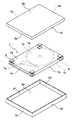
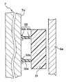
図2は、蓋体5で閉蓋されている収納部に収納するハードディスクケース(以下、ケースと略す)6の分解斜視図である。HDD7は、電極7a、記憶ディスク(以下、ディスクと略す)7b、ディスク7bと平行で下側筐体を形成する下面7c、上側筐体を構成する上面7d、ヘッド7e、ディスク7bおよびヘッド7eを介して電極7aと対向する対向側面7f、電極7aから見て左側の左側面7gおよび右側の右側面7hで構成される。HDD7に内蔵するヘッド7eは、ディスク7bに対して情報データの授受を担い、操作筐体1の内部空間に備える回路基板に情報データを送受信する。このため、HDD7には電極7aを備える。   FIG. 2 is an exploded perspective view of a hard disk case (hereinafter abbreviated as “case”) 6 that is housed in a housing portion that is closed with a lid 5. The HDD 7 includes an electrode 7a, a storage disk (hereinafter abbreviated as a disk) 7b, a lower surface 7c that forms a lower housing parallel to the disk 7b, an upper surface 7d that constitutes the upper housing, a head 7e, a disk 7b, and a head 7e. And the left side surface 7g on the left side when viewed from the electrode 7a and the right side surface 7h on the right side. The head 7 e built in the HDD 7 exchanges information data with the disk 7 b and transmits / receives information data to / from a circuit board provided in the internal space of the operation housing 1. For this reason, the HDD 7 includes an electrode 7a.

ケース6は、HDD7の下面7cが面的に対向する下側主面6a、上面7dが面的に対向する上側主面6b、電極7a側の電極下側面6c、電極下側面6cとHDD7を介して対向する対向下側面6d、電極下側面6cから見て右側の下側右側面6e、電極下側面6cから見て左側の下側左側面6f、電極7a側の電極上側面6g、電極上側面6gとHDD7を介して対向する対向上側側面6h、電極上側面6gから見て右側の上側右側面6i、電極上側面6gから見て左側の上側左側面6jとで構成される。HDD7は駆動する際に発熱するため、発生した熱を放熱させる貫通孔を、例えばケース6の上側主面6bに設けても良い。なお、HDD7は、操作筐体1の内部空間に内蔵する回路基板とヘッド7eを介して電気信号を授受するため、HDD7の制御をおこなう制御基板12(後述)を実装している。したがって、一般的に電気絶縁性のケース6に収納されているが、放熱効率をさらに向上させるため、例えばアルミニウム等の金属板が適用される場合もある。ケース6に金属板を用いる構成では、HDD7とケース6との間に電気絶縁性の絶縁部材13(後述)を介在させる。本実施形態のケース6には、アクリロニトリル・スチレン共重合体樹脂を適用した。   The case 6 includes a lower main surface 6a where the lower surface 7c of the HDD 7 faces the surface, an upper main surface 6b where the upper surface 7d faces the surface, the electrode lower surface 6c on the electrode 7a side, the electrode lower surface 6c and the electrode 7 via the HDD 7. Opposite lower side surface 6d, lower right side surface 6e on the right side viewed from the electrode lower side surface 6c, lower left side surface 6f on the left side viewed from the lower electrode side surface 6c, upper electrode side surface 6g on the electrode 7a side, upper electrode side surface 6g and the opposite upper side surface 6h through the HDD 7, an upper right side surface 6i on the right side when viewed from the electrode upper side surface 6g, and an upper left side surface 6j on the left side when viewed from the electrode upper side surface 6g. Since the HDD 7 generates heat when being driven, a through hole for radiating the generated heat may be provided in the upper main surface 6 b of the case 6, for example. The HDD 7 is mounted with a control board 12 (described later) for controlling the HDD 7 in order to send and receive electrical signals via a circuit board built in the internal space of the operation housing 1 and the head 7e. Therefore, although it is generally housed in the electrically insulating case 6, a metal plate such as aluminum may be applied in order to further improve the heat dissipation efficiency. In the configuration using a metal plate for the case 6, an electrically insulating insulating member 13 (described later) is interposed between the HDD 7 and the case 6. In case 6 of this embodiment, acrylonitrile / styrene copolymer resin was applied.

ケース6の下側主面6aとHDD7の下面7cとの間に、下側緩衝材8を介在させている。下側緩衝材8は、HDD7における各角部近傍に配置されている。下側緩衝材8は、ケース6の下側主面6aとHDD7下面7cとの間に配置され、HDD7の自重を支持する。また、上側主面6bとHDD7の上面7dとの間に上側緩衝材9を介在させている。上側緩衝材9は、HDD7の自重が加わる下面7cにディスク7bを介して対向する上面7dに配置される。上側主面6bと上面7dとの間に配置する上側緩衝材9は、HDD7の自重が加えられる下面7cと反対側の上面7dに備わるため、通常の使用状態ではHDD7からの荷重が印加されることは少ない。このため、ケース6の上側主面6bと下側主面6aとを固定する際に、上面7dと上側主面6との密着性を向上することを主目的として配置される。したがって、上側緩衝材9は、後述する第2緩衝材10のような直方体形状や、後述する第1緩衝材11のような構成であってもよい。 A lower cushioning material 8 is interposed between the lower main surface 6 a of the case 6 and the lower surface 7 c of the HDD 7. The lower cushioning material 8 is disposed in the vicinity of each corner of the HDD 7. The lower cushioning material 8 is disposed between the lower main surface 6 a of the case 6 and the lower surface 7 c of the HDD 7 and supports the weight of the HDD 7. An upper cushioning material 9 is interposed between the upper main surface 6 b and the upper surface 7 d of the HDD 7. The upper cushioning material 9 is disposed on the upper surface 7d facing the lower surface 7c to which the own weight of the HDD 7 is applied via the disk 7b. Since the upper cushioning material 9 disposed between the upper main surface 6b and the upper surface 7d is provided on the upper surface 7d opposite to the lower surface 7c to which the weight of the HDD 7 is applied, a load from the HDD 7 is applied in a normal use state. There are few things. Therefore, when fixing the upper major surface 6b of the case 6 and a lower major surface 6a, it is arranged to improve the adhesion between the top surface 7d and the upper main surface 6 b the main purpose. Therefore, the upper cushioning material 9 may have a rectangular parallelepiped shape like the second cushioning material 10 described later or a configuration like the first cushioning material 11 described later.

HDD7およびケース6の詳細な構成について、図3および図4を参照して説明する。図3は、HDD7の下面7c側から見た平面図で、図4は、分解側面図である。なお、図3は、煩雑性を避けるため、後述するケース6の下側主面6aおよびドライブ固定部51の固定主面51aを省いている。   Detailed configurations of the HDD 7 and the case 6 will be described with reference to FIGS. 3 and 4. 3 is a plan view seen from the lower surface 7c side of the HDD 7, and FIG. 4 is an exploded side view. In FIG. 3, in order to avoid complexity, a lower main surface 6 a of the case 6 and a fixed main surface 51 a of the drive fixing portion 51 described later are omitted.

HDD7は、内蔵されるヘッド7eからデータの授受をする電極7a、下面7c、ディスク7bおよびヘッド7eを介して下面7cに対向する上面7dで構成される。また、HDD7に収納されるディスク7bの回転駆動やヘッド7eのディスクに対する位置調整等の制御を行う制御基板12が、HDD7の上面7dに一体的に形成されている。なお、本実施形態では制御基板12はHDD7の上面7d側に備えたが、下面7c側でも同様である。制御基板12は、回路基板がそのまま積層されているため、電気的に保護する必要があり、本実施形態では、絶縁部材13を介して、上側緩衝材9、第1緩衝材11および第2緩衝材10を貼付した。なお、絶縁部材13としては、電気絶縁性の例えばポリエチレンテレフタレートフィルム等を適用でき、本実施形態では厚み5μmのポリエチレンテレフタレートフィルムを用いた。   The HDD 7 includes an electrode 7a for transferring data from a built-in head 7e, a lower surface 7c, a disk 7b, and an upper surface 7d facing the lower surface 7c via the head 7e. In addition, a control board 12 that controls the rotational drive of the disk 7b accommodated in the HDD 7 and the position adjustment of the head 7e with respect to the disk is integrally formed on the upper surface 7d of the HDD 7. In the present embodiment, the control board 12 is provided on the upper surface 7d side of the HDD 7, but the same applies to the lower surface 7c side. Since the circuit board is laminated as it is, the control board 12 needs to be electrically protected. In the present embodiment, the upper cushioning material 9, the first cushioning material 11, and the second cushioning material are interposed via the insulating member 13. Material 10 was affixed. As the insulating member 13, an electrically insulating polyethylene terephthalate film or the like can be applied. In this embodiment, a polyethylene terephthalate film having a thickness of 5 μm is used.

すなわち、HDD7の下面7cには、第2緩衝材10と、第2緩衝材10に隣り合って配置した第1緩衝材11とを絶縁部材13に接着剤で貼付した。また、HDD7の上面7dには、上側緩衝材9を絶縁部材13に接着剤で貼付した。なお、本実施形態における第2緩衝材10は、形状的には直方体や立方体で、特性的には押圧すると当該押圧力にみあう復元力を生起するまで変形し、当該押圧力の印加がなくなると元の形状に復元する。構成的には、第2緩衝材10の一方の面はケース6の下側主面6a側に対向して配され、この第2緩衝材10におけるHDD7の下面7の中央側側面それぞれに並列して第1緩衝材11(後述)が配置される。第2緩衝材10に供する材質としては、例えばエチレン・プロピレンゴムやフッ素ゴム等のゴム系、ウレタンやポリエチレン等を発泡処理した発泡体等が挙げられる。また、第2緩衝材10には上述した単体だけではなく、例えば特開2009−264483号公報に開示されている衝撃吸収部と振動減衰部との複合緩衝材、特開2004−315087号公報や特開2008−291986号公報等で開示されている板状部材の切断端面を柔軟材料中に埋没させた複合緩衝材等であっても本実施形態の第2緩衝材10に適用することができる。本実施形態では、HDD7の長手方向に沿う長さ2.5mm、短手方向の幅2.2mm、自然長の高さ7.5mmの発泡ウレタンフォームを用いた。 That is, the second cushioning material 10 and the first cushioning material 11 disposed adjacent to the second cushioning material 10 are attached to the insulating member 13 with an adhesive on the lower surface 7 c of the HDD 7. Further, the upper cushioning material 9 was attached to the insulating member 13 with an adhesive on the upper surface 7 d of the HDD 7. Note that the second cushioning material 10 in the present embodiment is a rectangular parallelepiped or a cube in shape, and when it is pressed, it is deformed until a restoring force that matches the pressing force is generated, and the pressing force is no longer applied. And restore the original shape. The constitutive, one surface of the second cushioning member 10 is disposed to face the lower principal surface 6a side of the case 6, parallel to each central side surface of the second lower surface 7 of HDD7 in buffer material 10 c And the 1st shock absorbing material 11 (after-mentioned) is arrange | positioned. Examples of the material used for the second cushioning material 10 include rubbers such as ethylene / propylene rubber and fluorine rubber, and foams obtained by foaming urethane or polyethylene. Further, the second cushioning material 10 is not limited to the above-described simple substance, for example, a composite cushioning material of an impact absorbing portion and a vibration damping portion disclosed in Japanese Patent Laid-Open No. 2009-264483, Japanese Patent Laid-Open No. 2004-315087, Even a composite cushioning material or the like in which a cut end surface of a plate-like member disclosed in JP 2008-291986 A is embedded in a flexible material can be applied to the second cushioning material 10 of the present embodiment. . In this embodiment, a foamed urethane foam having a length of 2.5 mm along the longitudinal direction of the HDD 7, a width of 2.2 mm in the short side direction, and a natural length of 7.5 mm is used.

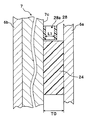
また、本実施形態における第1緩衝材11は、HDD7等に印加される外乱が第2緩衝材10の衝撃緩和能力を超えるとき屈曲変形する座屈部11aと、座屈部11aを支持する支持部11bとで構成される。また、座屈部11aは形状的には中空の円筒形状で、構成的にはHDD7の下面7cに密着配置する。すなわち、HDD7に付与される外乱が第2緩衝材10に伝えられ、第2緩衝材10で緩和吸収できない余剰分の荷重は、第1緩衝材11の座屈部11aが座屈することで、屈曲変形に起因して生じる復元力が当該荷重にみあうだけ変形し、荷重が除去されると元の形状に復元する。また、座屈部11aが座屈する際の荷重の大きさは、第1緩衝材11の座屈部11aにおける中空円筒における断面の厚みの大きさで調整することができる。   In addition, the first shock absorber 11 in the present embodiment includes a buckling portion 11a that bends and deforms when a disturbance applied to the HDD 7 or the like exceeds the impact mitigation ability of the second shock absorber 10, and a support that supports the buckling portion 11a. Part 11b. Further, the buckling portion 11a is in the shape of a hollow cylinder and is structurally arranged in close contact with the lower surface 7c of the HDD 7. That is, the disturbance applied to the HDD 7 is transmitted to the second cushioning material 10, and the excess load that cannot be relaxed and absorbed by the second cushioning material 10 is bent by the buckling portion 11 a of the first cushioning material 11 buckling. The restoring force generated due to the deformation is deformed so as to match the load, and when the load is removed, the original shape is restored. Moreover, the magnitude | size of the load at the time of buckling part 11a buckling can be adjusted with the magnitude | size of the thickness of the cross section in the hollow cylinder in the buckling part 11a of the 1st shock absorbing material 11. FIG.

第1緩衝材11は、上述した座屈部11aをHDD7の下面7cから支持する支持部11bを備える。支持部11bは、座屈部11aの中空円筒断面によりHDD7の下面7cに与える損傷を緩和し、同時にHDD7に対する座屈部11aの位置決めの役目も担う。このため、支持部11bは、下面7cに沿う所望の広さを有する平面で構成される。本実施の形態における支持部11bは、座屈部11aと同一材料で一体的に形成したが、別部材であっても良い。第1緩衝材11、特に座屈部11aに供する材質としては、天然ゴムやシリコーンゴムやスチレン・ブタジエン系合成ゴム等のゴム材料または熱可塑性エラストマーを供することができる。また、支持部11bに供する材料と座屈部11aに供する材料とが異なる場合には、支持部11bとして下面7cに沿う例えばポリエチレンテレフタレートやポリアミド等の可撓性材料や、表面に粘着性を備える可塑化樹脂やゲル等が適用できる。なお、本実施形態における第1緩衝材11の座屈部11aは第2緩衝材10に対し2個備えた場合であるが、第2緩衝材10の1つの側面に沿って配列すればよい。また、第2緩衝材10の一側面の長さに応じて座屈部11aの配列数は決定すればよい。本実施形態の座屈部11aは、第2緩衝材10の側面に単一備えると、HDD7の揺動または傾斜動作(後述)に対して不安定となる場合があるため、2個備える構成とした。また、図3に示したように、第2緩衝材10が相対向する側面それぞれに備えたが、第2緩衝材10が相対向する一対の側面の何れかにのみ備えてもよく、さらには第2緩衝材10を取り囲むように各側面それぞれに配置してもよい。なお、一例として本実施形態では、座屈部11aとしては支持部11b表面からの高さ4mm、直径4mm、肉厚1mmの円柱形状をピッチ7mmで配置した。また、支持部11bとしては、厚み1mm、第2緩衝材10の側面に直交する方向の距離はそれぞれ2mmである。なお、座屈部11aの材質は共にシリコーンゴムを供した。   The first cushioning material 11 includes a support portion 11 b that supports the buckling portion 11 a described above from the lower surface 7 c of the HDD 7. The support portion 11b alleviates damage to the lower surface 7c of the HDD 7 due to the hollow cylindrical cross section of the buckling portion 11a, and also serves to position the buckling portion 11a with respect to the HDD 7. For this reason, the support part 11b is comprised by the plane which has the desired width along the lower surface 7c. Although the support part 11b in this Embodiment was integrally formed with the same material as the buckling part 11a, another member may be sufficient. As the material to be used for the first buffer material 11, particularly the buckling portion 11a, a rubber material such as natural rubber, silicone rubber, styrene / butadiene synthetic rubber, or a thermoplastic elastomer can be used. Further, when the material provided for the support portion 11b is different from the material provided for the buckling portion 11a, the support portion 11b is provided with a flexible material such as polyethylene terephthalate or polyamide along the lower surface 7c, or has a sticky surface. Plasticized resin or gel can be applied. In addition, although the buckling part 11a of the 1st shock absorbing material 11 in this embodiment is a case where two pieces are provided with respect to the 2nd shock absorbing material 10, what is necessary is just to arrange | position along one side surface of the 2nd shock absorbing material 10. FIG. Further, the number of buckling portions 11a may be determined according to the length of one side surface of the second cushioning material 10. Since the buckling portion 11a of the present embodiment may be unstable with respect to the swinging or tilting operation (described later) of the HDD 7 if a single buckling portion 11a is provided on the side surface of the second cushioning material 10, the configuration includes two. did. In addition, as shown in FIG. 3, the second cushioning material 10 is provided on each of the opposing side surfaces, but the second cushioning material 10 may be provided only on one of a pair of opposing side surfaces, You may arrange | position to each side surface so that the 2nd shock absorbing material 10 may be surrounded. As an example, in this embodiment, a cylindrical shape having a height of 4 mm, a diameter of 4 mm, and a thickness of 1 mm from the surface of the support portion 11 b is arranged at a pitch of 7 mm as the buckling portion 11 a. Moreover, as the support part 11b, the distance of the direction orthogonal to the side surface of the thickness 1mm and the 2nd shock absorbing material 10 is 2 mm, respectively. The buckling portion 11a was made of silicone rubber.

したがって、後述の図5Aにおける下側主面6a(第2緩衝材10の下側主面6a側と同じ)と、座屈部11aにおける下側主面6aに対抗する面との離隔距離dは、2.5mmである。   Therefore, a separation distance d between a lower main surface 6a (same as the lower main surface 6a side of the second cushioning material 10) in FIG. 5A described later and a surface facing the lower main surface 6a of the buckling portion 11a is 2.5 mm.

HDD7の電極7aとPCの回路基板とを電気的に接続し、HDD7をPCの操作筐体1に固定するため、制御基板12を備えるHDD7はドライブ固定部51に実装される。ドライブ固定部51は、ケース6の下側主面6aを支持する固定主面51a、下側左側面6fおよび下側右側面6eそれぞれに対向する一対の固定側面51b、ケース6の電極上側面6gおよび電極下側面6c側の接続側側面51c、接続側側面51c側で接続PCの回路基板に電気信号の授受を担う接続部51d、例えばフレキシブル配線でHDD7の電極7aに電気的に接続する端子電極51f、固定主面51aを介して接続側側面51cの反対側で対向する対向側面51eで構成される。   In order to electrically connect the electrode 7 a of the HDD 7 and the circuit board of the PC and fix the HDD 7 to the operation casing 1 of the PC, the HDD 7 including the control board 12 is mounted on the drive fixing portion 51. The drive fixing portion 51 includes a fixed main surface 51 a that supports the lower main surface 6 a of the case 6, a pair of fixed side surfaces 51 b that face the lower left side surface 6 f and the lower right side surface 6 e, and the electrode upper side surface 6 g of the case 6. And the connection side surface 51c on the electrode lower side surface 6c side, and the connection side 51d for transferring electrical signals to the circuit board of the connection PC on the connection side surface 51c side, for example, a terminal electrode electrically connected to the electrode 7a of the HDD 7 by flexible wiring 51f, it is constituted by an opposing side surface 51e that is opposed to the connection side surface 51c via the fixed main surface 51a.

なお、ドライブ固定部51の一対の固定側面51bは、ケース6の下側左側面6fおよび下側右側面6eそれぞれを内側として固着される。したがって、ケース6とドライブ固定部51とは一体の挙動を示す。また、ケース6の下側左側面6fおよび下側右側面6eにはそれぞれ一対の係合部6kを備え、上側左側面6jおよび上側右側面6iそれぞれに一対備える係合凸部6lに嵌合する。なお、下側左側面6fおよび下側右側面6eそれぞれは上側左側面6jおよび上側右側面6iに近接するように付勢されている。このため、係合部6kと係合凸部6lとは、HDD7を収納したケース6を固着でき、ケース6を介してHDD7はドライブ固定部51に固定される。   The pair of fixed side surfaces 51b of the drive fixing portion 51 are fixed with the lower left side surface 6f and the lower right side surface 6e of the case 6 as inner sides. Therefore, the case 6 and the drive fixing part 51 exhibit an integral behavior. Further, the lower left side surface 6f and the lower right side surface 6e of the case 6 are each provided with a pair of engaging portions 6k, and are fitted to the engaging convex portions 6l provided as a pair on the upper left side surface 6j and the upper right side surface 6i. . The lower left side surface 6f and the lower right side surface 6e are urged so as to be close to the upper left side surface 6j and the upper right side surface 6i, respectively. For this reason, the engaging portion 6k and the engaging convex portion 6l can fix the case 6 housing the HDD 7, and the HDD 7 is fixed to the drive fixing portion 51 via the case 6.

HDD7の電極7aと操作筐体1の回路基板とは、電極7aに端子電極51fを接続させることで、接続部51dを介して電気的に接続する。接続部51dは、操作筐体の回路基板等に備える端子に接続されることで、HDD7はPCで駆動される。   The electrode 7a of the HDD 7 and the circuit board of the operation housing 1 are electrically connected via the connection portion 51d by connecting the terminal electrode 51f to the electrode 7a. The connection portion 51d is connected to a terminal provided on a circuit board or the like of the operation casing, so that the HDD 7 is driven by a PC.

[1−2.HDDの緩衝構成]
以上のようにドライブ固定部51に固定したHDD7の緩衝構成を、図5A乃至図5Cに、図3のA−A矢視断面形状で示す。すなわち、HDD7の下面7cに絶縁部材13を介して第1緩衝材11および第2緩衝材10を配置し、HDD7の上面7dに制御基板12および絶縁部材13を介して上側緩衝材9を配置した。なお、外乱に起因して衝撃がケース6に印加されたとしても、上述したようにケース6は係合部6kと係合凸部6lで嵌合されているため、下側主面6aおよび上側主面6bとの間隔は不変である。また、係合部6kと係合凸部6lとで嵌合しているため、ケース6に収容した上側緩衝材9と下側緩衝材8(後述するが第2緩衝材10)はケース6に圧入されている。
[1-2. HDD buffer configuration]
The buffer configuration of the HDD 7 fixed to the drive fixing unit 51 as described above is shown in FIGS. 5A to 5C in a cross-sectional shape taken along the line AA in FIG. That is, the first buffer material 11 and the second buffer material 10 are arranged on the lower surface 7 c of the HDD 7 via the insulating member 13, and the upper buffer material 9 is arranged on the upper surface 7 d of the HDD 7 via the control board 12 and the insulating member 13. . Even if an impact is applied to the case 6 due to a disturbance, the case 6 is fitted with the engaging portion 6k and the engaging convex portion 61 as described above, and therefore, the lower main surface 6a and the upper side The distance from the main surface 6b is unchanged. Further, since the engaging portion 6k and the engaging convex portion 61 are fitted, the upper cushioning material 9 and the lower cushioning material 8 (second cushioning material 10 described later) housed in the case 6 are attached to the case 6. It is press-fitted.

ケース6に外乱の印加前の状態を図5Aに示す。上側緩衝材9は厚みt0を有し、第2緩衝材10は厚みT0を有している。また、下側主面6aと第1緩衝材11の座屈部11aとは、間隙dを備えている。したがって、第1緩衝材11は、外乱に起因した衝撃を第2緩衝材10が間隙dだけ収縮するまでは衝撃を受けることがない。また、第2緩衝材10の厚みT0は、HDD7および制御基板12の自重(絶縁部材13の自重は無視できる程度であるため割愛する)と、上側緩衝材9の押圧力とにより収縮した結果である。上側緩衝材9の厚みt0は、第2緩衝材10の押圧力と、HDD7および制御基板12の自重とにより圧縮した結果である。   FIG. 5A shows a state before the disturbance is applied to the case 6. The upper cushioning material 9 has a thickness t0, and the second cushioning material 10 has a thickness T0. Further, the lower main surface 6a and the buckling portion 11a of the first buffer material 11 are provided with a gap d. Therefore, the first shock absorbing material 11 does not receive the shock due to the disturbance until the second shock absorbing material 10 contracts by the gap d. Further, the thickness T0 of the second cushioning material 10 is a result of contraction due to the weight of the HDD 7 and the control board 12 (omitted since the weight of the insulating member 13 is negligible) and the pressing force of the upper cushioning material 9. is there. The thickness t0 of the upper cushioning material 9 is a result of compression by the pressing force of the second cushioning material 10 and the weight of the HDD 7 and the control board 12.

ケース6に外乱を付与され、この外乱に起因する衝撃F1が印加されたときを図5Bに示す。衝撃F1の印加により、第2緩衝材10は間隙dだけ収縮し厚みT1となり、上側緩衝材9は厚みt1で釣り合う。したがって、第1緩衝材11の座屈部11aは、衝撃F1までは座屈を生じることがない。また、下側主面6aと上側主面6bとの間隔は不変であり、HDD7や制御基板12や絶縁部材13の厚みは変動さないため、t1−t0=T0−T1となる。すなわち、座屈部11aは、HDD7に印加される衝撃に対し、所定の値(本実施形態ではF1)以下の範囲では座屈することがない。   FIG. 5B shows a case where a disturbance is applied to the case 6 and an impact F1 resulting from the disturbance is applied. By applying the impact F1, the second cushioning material 10 contracts by the gap d to a thickness T1, and the upper cushioning material 9 balances with the thickness t1. Therefore, the buckling portion 11a of the first buffer material 11 does not buckle until the impact F1. Further, the distance between the lower main surface 6a and the upper main surface 6b is not changed, and the thicknesses of the HDD 7, the control board 12, and the insulating member 13 do not vary, so that t1−t0 = T0−T1. That is, the buckling portion 11a does not buckle in a range equal to or less than a predetermined value (F1 in this embodiment) with respect to the impact applied to the HDD 7.

この状態から、第1緩衝材11の座屈部11aが座屈する力より強い衝撃F2がHDD7に加えられると、図5Cに示したように、第2緩衝材10および座屈部11aが衝撃F2に応じて厚みT1からT2に収縮し、座屈部11aが座屈(屈曲変形)する。同時に、上側緩衝材9は、厚み(T1−T2)だけ復元して伸長する。換言すると、第1緩衝材11の座屈部11aは、HDD7の所定の値衝撃F1を超えたとき座屈を生起する。このように、HDD7は、第2緩衝材10、第1緩衝材11および上側緩衝材9によって衝撃(F2−F1)が緩和される。   From this state, when an impact F2 stronger than the buckling force of the buckling portion 11a of the first cushioning material 11 is applied to the HDD 7, the second cushioning material 10 and the buckling portion 11a are impacted F2 as shown in FIG. 5C. Accordingly, the thickness shrinks from T1 to T2, and the buckling portion 11a buckles (bends). At the same time, the upper cushioning material 9 is restored by its thickness (T1-T2) and extends. In other words, the buckling portion 11a of the first cushioning material 11 causes buckling when it exceeds a predetermined value impact F1 of the HDD 7. Thus, the impact (F2-F1) of the HDD 7 is mitigated by the second cushioning material 10, the first cushioning material 11, and the upper cushioning material 9.

また、座屈部11aの座屈現象は、例えば図5Cに示したように、第1緩衝材11の座屈部11aが復元性を維持した屈曲変形する。このとき、ケース6の下側主面6aが、座屈部11aにおける下側主面6a側の端面を閉塞することで、座屈部11a中の中空が閉ざされ、座屈部11aは太鼓状に弾性変形する。したがって、座屈部11aの屈曲方向は座屈部11aにおける立設方向の中心線に関して対称に変形し、衝撃F2の印加に対する座屈部11aの屈曲方向は常に個々の座屈部11aで同じ方向となる。しかも中空に収納される空気は復元性を有する収縮であり、この空気が座屈部11aの復元性を助成する。さらに、第1緩衝材11を第2緩衝材10の1つの側面に2個備えることで、例えばHDD7の傾斜や揺動に対しても平均した復元力を与えることができる。したがって、屈曲動作で第1緩衝材11に付与された荷重を緩和することができ、座屈部11aが配置位置によって面方向にランダムに変形することで、例えばHDD7に付与した衝撃に起因して発生する傾斜や揺動を抑制することができる。なお、座屈した座屈部11aは復元性を備えているため、衝撃F2の印加を除去すると、衝撃F1までは図5Cの状態で、衝撃F1で図5Bの状態となり、衝撃F1より小さい衝撃では図5Aに復帰する。また、外乱による反復振動が生じる場合には、図5A乃至図5Cを繰り返すことで、衝撃を緩和することができる。   Further, the buckling phenomenon of the buckling portion 11a is bent and deformed while the buckling portion 11a of the first cushioning material 11 maintains the restoring property as shown in FIG. 5C, for example. At this time, the lower main surface 6a of the case 6 closes the end surface of the buckling portion 11a on the lower main surface 6a side, so that the hollow in the buckling portion 11a is closed, and the buckling portion 11a has a drum shape. It is elastically deformed. Therefore, the bending direction of the buckling portion 11a deforms symmetrically with respect to the center line of the standing direction in the buckling portion 11a, and the bending direction of the buckling portion 11a with respect to the application of the impact F2 is always the same direction in each buckling portion 11a. It becomes. Moreover, the air stored in the hollow is a contraction having resilience, and this air assists the resilience of the buckling portion 11a. Furthermore, by providing two first buffer members 11 on one side surface of the second buffer member 10, for example, it is possible to give an average restoring force even when the HDD 7 is tilted or swung. Therefore, the load applied to the first cushioning material 11 by the bending operation can be relaxed, and the buckling portion 11a is randomly deformed in the surface direction depending on the arrangement position, for example, due to an impact applied to the HDD 7. The generated tilt and swing can be suppressed. Since the buckled buckled portion 11a has resilience, when the application of the impact F2 is removed, the state up to the impact F1 is in the state of FIG. 5C, the state of the impact F1 is the state of FIG. 5B, and the impact is smaller than the impact F1. Returning to FIG. 5A. In addition, when repetitive vibration occurs due to disturbance, the impact can be reduced by repeating FIGS. 5A to 5C.

なお、支持部11bは、柱状の断面積でHDD7の下面7cに当接することを緩和することができる。また、支持部11bは下面7cの外形面に確実に沿わせることができる。このため、座屈部11aのHDD7に対する位置決めができ、HDD7に対する損傷を抑制することができ、また座屈部11aの確実な支持が達成できる。さらに、支持部11bを座屈部11aとケース6の下側主面6aとの接触面に備える構成の場合には、図5Cにおける中空に収納した空気をより確実に閉じ込められ、座屈部11aの屈曲性および復元性をより向上する。また、本実施形態では、座屈部11aの中空部を支持部11bに備えた構成であるため、座屈部11aの座屈変形は支持部11bまで及ぼすことができる。   In addition, the support part 11b can relieve | moderate contact | abutting with the lower surface 7c of HDD7 with a column-shaped cross-sectional area. Moreover, the support part 11b can be surely along the external surface of the lower surface 7c. Therefore, the buckling portion 11a can be positioned with respect to the HDD 7, damage to the HDD 7 can be suppressed, and reliable support of the buckling portion 11a can be achieved. Furthermore, in the case of a configuration in which the support portion 11b is provided on the contact surface between the buckling portion 11a and the lower main surface 6a of the case 6, the air stored in the hollow in FIG. 5C can be more reliably confined, and the buckling portion 11a. The bendability and the restorability are further improved. Moreover, in this embodiment, since it is the structure which provided the hollow part of the buckling part 11a in the support part 11b, the buckling deformation of the buckling part 11a can exert to the support part 11b.

なお、本実施形態では、衝撃F2が印加され第2緩衝材10の圧縮および第1緩衝材11の座屈で厚みT2でも、上側緩衝材9の復元範囲にあるとして説明したが、上側緩衝材9の復元限界を超えた場合には、上側緩衝材9は絶縁部材13または上側主面6bの何れかの界面で剥離される。なお、本実施形態では、上側緩衝材9はHDD7の上面7d側の絶縁部材13で貼着されているため、上側主面6bの界面で剥離する。   In the present embodiment, the shock absorber F2 is applied and the compression of the second shock absorber 10 and the buckling of the first shock absorber 11 cause the thickness T2 to be within the restoring range of the upper shock absorber 9. When the recovery limit of 9 is exceeded, the upper cushioning material 9 is peeled off at the interface of either the insulating member 13 or the upper main surface 6b. In the present embodiment, since the upper cushioning material 9 is attached by the insulating member 13 on the upper surface 7d side of the HDD 7, it is peeled off at the interface of the upper main surface 6b.

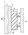
また、第1緩衝材11は支持部11bまで座屈部11aと同じ中空として説明したが、図6に示すように、座屈部14aは板状の支持部14bから立設していてもよい。すなわち、座屈部14aが中空に構成されている。   Moreover, although the 1st shock absorbing material 11 demonstrated as the hollow same as the buckling part 11a to the support part 11b, as shown in FIG. 6, the buckling part 14a may be standingly arranged from the plate-shaped support part 14b. . That is, the buckling portion 14a is configured to be hollow.

[1−3.HDDの構成]
図7は、HDD7を収納するケース15の概略構成を示す分解斜視図である。HDD7の構成は同一であるため、説明は割愛する。
[1-3. Configuration of HDD]
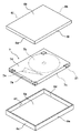
FIG. 7 is an exploded perspective view showing a schematic configuration of the case 15 that houses the HDD 7. Since the configuration of the HDD 7 is the same, the description is omitted.

このHDD7は、上面7dに接着剤を介して上側緩衝材18を貼付し、下面7cに接着剤を介して下側緩衝材17を貼付した。すなわち、下側緩衝材17は第1緩衝材11および第2緩衝材10で構成されている点は前述の実施形態と同じである。なお、上述のHDD7は一例であり、例えば制御基板12および絶縁部材13を備える構成や、上側緩衝材18を備えない構成であっても同じである。また、下側緩衝材17および上側緩衝材18に適用した材料や構成は、全て先の実施形態と同一であるため説明は割愛する。   In this HDD 7, an upper cushioning material 18 is stuck on the upper surface 7d via an adhesive, and a lower cushioning material 17 is stuck on the lower surface 7c via an adhesive. That is, the lower buffer material 17 is the same as the above-described embodiment in that it is composed of the first buffer material 11 and the second buffer material 10. Note that the HDD 7 described above is an example, and for example, the configuration including the control board 12 and the insulating member 13 and the configuration without the upper cushioning material 18 are the same. Further, since the materials and configurations applied to the lower cushioning material 17 and the upper cushioning material 18 are all the same as those in the previous embodiment, description thereof will be omitted.

このHDD7を収納するハードディスクケース15は、上側からHDD7を収容する上側主面15b、HDD7の電極7a側の電極上側面15g、電極上側面15gに上側主面15bを介して対向する上側対向側面15h、電極上側面15gから見て右側の上側右側面15iおよび左側の上側左側面15j、下側からHDD7を収容する下側主面15a、HDD7の電極7a側の電極下側面15c、電極下側面15cに下側主面15aを介して対向する下側対向側面15d、電極下側面15cから見て右側の下側右側面15eおよび左側の下側左側面15fで構成される。また、ケース15の下側主面15aにおける各4角近傍には、下側主面15aの4角を形成する2側面に沿った角部で繋がるスリット16を備えている。   The hard disk case 15 for housing the HDD 7 includes an upper main surface 15b for housing the HDD 7 from above, an electrode upper side surface 15g on the electrode 7a side of the HDD 7, and an upper facing side surface 15h facing the electrode upper side surface 15g via the upper main surface 15b. The upper right side surface 15i on the right side and the upper left side surface 15j on the left side as viewed from the electrode upper side surface 15g, the lower main surface 15a for housing the HDD 7 from the lower side, the electrode lower side surface 15c on the electrode 7a side of the HDD 7, and the electrode lower side surface 15c The lower opposing side surface 15d that faces the lower main surface 15a, the lower right side surface 15e on the right side as viewed from the electrode lower side surface 15c, and the lower left side surface 15f on the left side. Further, in the vicinity of each of the four corners of the lower main surface 15a of the case 15, there are provided slits 16 connected by corner portions along two side surfaces forming the four corners of the lower main surface 15a.

[1−4.HDDの緩衝構成2]
図8は、このように構成した下側主面15aにHDD7を載置した状態を、HDD7の上面7dから下側を見た部分平面図である。下側主面15aに備えるスリット16は、下側対向側面15dおよび下側左側面15fが構成する角部を一例として挙げている。
[1-4. HDD buffer configuration 2]
FIG. 8 is a partial plan view of the state in which the HDD 7 is placed on the lower main surface 15 a configured as described above, as viewed from the upper surface 7 d of the HDD 7. The slit 16 provided in the lower main surface 15a has exemplified a corner portion formed by the lower facing side surface 15d and the lower left side surface 15f as an example.

ケース15の下側主面15aは、可撓性を有するアクリロニトリル・スチレン共重合体樹脂である。このため、下側主面15aに備えるスリット16の角部16aは、下側対向側面15dに沿って形成されるスリット16の端部と、下側側面15fに沿って形成されるスリット16の端部とを結ぶ軸16bを中心として、上下方向に弾性的に撓む。なお、ケース15の材料は可撓性を有していることが好ましく、アクリロニトリル・スチレン共重合体樹脂やアクリロニトリル・ブタジエン・スチレン共重合体樹脂などを採用することもできる。ケース15の材料としては金属材料を採用することもできる。   The lower main surface 15a of the case 15 is a flexible acrylonitrile / styrene copolymer resin. For this reason, the corner | angular part 16a of the slit 16 with which the lower side main surface 15a is equipped is the edge part of the slit 16 formed along the lower side surface 15d, and the edge of the slit 16 formed along the lower side surface 15f. It bends elastically in the up-and-down direction around the axis 16b connecting the parts. Note that the material of the case 15 is preferably flexible, and acrylonitrile / styrene copolymer resin, acrylonitrile / butadiene / styrene copolymer resin, or the like may be employed. A metal material can be adopted as the material of the case 15.

また、HDD7の対向側面7fは、下側対向側面15d側でスリット16が成す外側切断辺と下側対向側面15dとの間に配置され、HDD7の左側面7gは、一方の下側側面15f側でスリット16が成す外側切断辺と下側側面15fとの間に配置される。また、HDD7の下面7cに貼着する下側緩衝材17の2つの側面は、スリット16のほぼ中央部に配置されている。しかも、下側緩衝材17の2側面は、HDD7の対向側面7fと左側面7gからHDD7との中心部に配置されているため、HDD7に付与される衝撃は、下側緩衝材17や上側緩衝材18の衝撃緩和に加え、軸16bを中心とする角部16aの撓みによっても衝撃を緩和することができる。したがって、下側主面15aの各角部近傍にスリット16を備えることで、HDD7に加えられる荷重で生じる衝撃を緩和することができる。   Further, the opposing side surface 7f of the HDD 7 is disposed between an outer cut side formed by the slit 16 on the lower opposing side surface 15d side and the lower opposing side surface 15d, and the left side surface 7g of the HDD 7 is on the lower side surface 15f side. The slit 16 is disposed between the outer cut side and the lower side surface 15f. Further, the two side surfaces of the lower cushioning material 17 attached to the lower surface 7 c of the HDD 7 are disposed at substantially the center of the slit 16. In addition, since the two side surfaces of the lower cushioning material 17 are arranged at the central portion of the HDD 7 from the opposite side surface 7f and the left side surface 7g of the HDD 7, the impact applied to the HDD 7 is affected by the lower cushioning material 17 and the upper cushioning material. In addition to mitigating the impact of the material 18, the impact can be mitigated by bending of the corner portion 16a centering on the shaft 16b. Therefore, by providing the slits 16 in the vicinity of each corner of the lower main surface 15a, it is possible to mitigate the impact caused by the load applied to the HDD 7.

[1−5.効果等]
第1緩衝材11の座屈部11aおよび第2緩衝材10をHDD7に対し配置した構成では、ケース6の下側主面6aおよび上側主面6b間に収納したHDD7に対し垂直方向の外乱は、上述した作用で衝撃緩和を達成することができる。また、外乱は必ずしも垂直方向のみとは限らず、HDD7の下面7cおよび上面7d方向に働く傾斜成分および/または揺動成分も生じる。この傾斜成分および/または揺動成分に対しても、前述したように座屈部11aは中空の円筒柱形状であるため、座屈部11aおよび座屈部11aに備える中空が協働して衝撃緩和し、HDD7の傾斜動作および/または揺動動作を緩和する効果を向上することができる。さらに、支持部11bを座屈部11aとHDD7との界面に備えることで、HDD7に対する第1緩衝材11の座屈部11aのより確実な設置を達成することができ、例えばHDD7の下面7cに対し垂直方向および/または平行方向の外乱に対する緩衝効果を向上させることができる。
[1-5. Effect]
In the configuration in which the buckling portion 11a of the first cushioning material 11 and the second cushioning material 10 are arranged with respect to the HDD 7, the disturbance in the vertical direction with respect to the HDD 7 accommodated between the lower main surface 6a and the upper main surface 6b of the case 6 is Impact relaxation can be achieved by the above-described action. Further, the disturbance is not necessarily limited to the vertical direction, and a tilt component and / or a swing component that acts in the direction of the lower surface 7c and the upper surface 7d of the HDD 7 are also generated. As described above, the buckling portion 11a has a hollow cylindrical column shape, and the buckling portion 11a and the hollow provided in the buckling portion 11a cooperate with each other for the inclination component and / or the swing component. The effect of mitigating and mitigating the tilting operation and / or the swinging operation of the HDD 7 can be improved. Further, by providing the support portion 11b at the interface between the buckling portion 11a and the HDD 7, a more reliable installation of the buckling portion 11a of the first cushioning material 11 with respect to the HDD 7 can be achieved. On the other hand, the buffering effect against disturbance in the vertical direction and / or parallel direction can be improved.

また、上述したように第2緩衝材10のみの収縮によりHDD7に印加される衝撃F1を緩衝し、F1よりも強い衝撃F2がHDD7に加えられると、衝撃(F2−F1)に起因する衝撃は第1緩衝材11及び第2緩衝材10で緩和する構成で説明した。このケース6内部における第2緩衝材10が、第1緩衝材11の座屈部11aよりd(本実施形態では2.5mm)だけ突出した構成により、HDD7に印加される衝撃を緩和することができる。すなわち、本実施形態における構成では、衝撃F1の印加時点で、第1緩衝材11を座屈させることがなく、第2緩衝材10の収縮だけで衝撃を緩和する。衝撃F1の印加後で、座屈部11aを座屈できる衝撃F2の印加で、衝撃差(F2−F1)で座屈部11aは座屈すると共に、第2緩衝材10の厚みがT2まで収縮することで、この衝撃差に対する衝撃を緩衝することができる。逆に、第1緩衝材11の座屈部11aが第2緩衝材10より突出する構成では、衝撃F1の印加でHDD7は座屈部11aに当接したとしても、座屈部11aは剛体状態でHDD7と当接するため、衝撃F1の印加に対しては衝撃緩衝を成し得ない。換言すると、座屈部11aが座屈する衝撃F2の印加までHDD7は剛体としての座屈部11aと当接するため、少なくとも衝撃F2の印加まではHDD7には印加される衝撃に対する反作用力が衝撃として直接加えられる。このため、HDD7に加え得られる衝撃に基づく衝撃を緩和するため、第2緩衝材10が第1緩衝材11の座屈部11a以上に突出している。なお、座屈部11aの高さと第2緩衝材10の高さとが同一(すなわち、d=0)の場合、衝撃F1の印加に対する第2緩衝材10のみの衝撃緩衝効果はなくなるが、例えば衝撃変動(F2−F1)が少ない場合等では有効に機能する。また、HDDに付与される衝撃、間隙dの長さは、HDD7の自重、第1緩衝材11及び第2緩衝材10の衝撃吸収性に応じて適宜設定できる。したがって、本実施形態で用いた2.5mmの長さdは一例であり、絶対的ではない。 Further, as described above, when the shock F1 applied to the HDD 7 is buffered by the contraction of only the second buffer material 10, and the shock F2 stronger than F1 is applied to the HDD 7, the shock due to the shock (F2-F1) is The description has been given of the configuration in which the first buffer material 11 and the second buffer material 10 relax. The second cushioning material 10 inside the case 6 projects from the buckling portion 11a of the first cushioning material 11 by d (2.5 mm in this embodiment), so that the impact applied to the HDD 7 can be reduced. it can. That is, in the configuration according to the present embodiment, the impact is alleviated only by contraction of the second cushioning material 10 without buckling the first cushioning material 11 when the impact F1 is applied. After application of the impact F1, by applying an impact F2 that can buckle the buckling portion 11a, the buckling portion 11a buckles due to the impact difference (F2-F1), and the thickness of the second cushioning material 10 contracts to T2. Thus, the impact against the impact difference can be buffered. On the contrary, in the configuration in which the buckling portion 11a of the first cushioning material 11 protrudes from the second cushioning material 10, even if the HDD 7 contacts the buckling portion 11a by application of the impact F1, the buckling portion 11a is in a rigid state. Because of the contact with the HDD 7, the shock buffering cannot be performed for the application of the shock F 1. In other words, the HDD 7 abuts against the buckling portion 11a as a rigid body until the impact F2 at which the buckling portion 11a buckles, so that the reaction force against the applied impact is directly applied to the HDD 7 as an impact at least until the impact F2 is applied. Added. For this reason, the second cushioning material 10 protrudes beyond the buckling portion 11 a of the first cushioning material 11 in order to reduce the impact based on the impact obtained in addition to the HDD 7. When the height of the buckling portion 11a and the height of the second buffer material 10 are the same (that is, d = 0), the shock buffering effect of only the second buffer material 10 against the application of the shock F1 is lost. It functions effectively when the fluctuation (F2-F1) is small. Further, the impact applied to the HDD and the length of the gap d can be appropriately set according to the own weight of the HDD 7 and the impact absorbability of the first buffer material 11 and the second buffer material 10. Therefore, the length d of 2.5 mm used in this embodiment is an example and is not absolute.

なお、第1緩衝材11は中空円筒形状を有する座屈部11aで説明したが、HDD7の下面7cと平行な面で切断した断面形状は円形に限らず多角形状であってもよい。下面7cに対して直交する方向に括れを有する形状(例えば一対の平面で両端部を切断したひょうたん形や、このひょうたん形の括れ部分で切断した半体等)であってもよい。断面形状を円形とした場合は360度方向からの外乱に対して略等しく緩衝効果を発揮することができる。また、中空構成の座屈部11aにおける解放側端部は下側主面6aで密閉される構成であるため、座屈部11aの形状としては半球形やドーム形でも適用することができる。さらに、座屈部11aにおける屈曲の方向を規定する必要性がない場合等では、中空形状とする必要がないため、第1緩衝材11を中心まで同一材料で構成することもできる。また、第1緩衝材11の外形形状が、例えば球形、半球形、回転楕円体、半回転楕円体、ひょうたん等の円形の曲面を備えると、第1緩衝材11に印加される振動方向を等方的に受け止めることができる。   In addition, although the 1st shock absorbing material 11 demonstrated the buckling part 11a which has a hollow cylindrical shape, the cross-sectional shape cut | disconnected by the surface parallel to the lower surface 7c of HDD7 may be not only circular but polygonal shape. The shape may be constricted in a direction orthogonal to the lower surface 7c (for example, a gourd shape having both ends cut by a pair of flat surfaces, or a half body cut by this gourd-shaped constricted portion). When the cross-sectional shape is circular, a buffering effect can be exhibited substantially equally with respect to disturbance from the 360 degree direction. Moreover, since the open | release side edge part in the buckling part 11a of a hollow structure is the structure sealed by the lower main surface 6a, hemispherical shape and dome shape can also be applied as a shape of the buckling part 11a. Furthermore, when there is no need to define the bending direction in the buckling portion 11a, the first buffer material 11 can be made of the same material up to the center because it is not necessary to have a hollow shape. In addition, when the outer shape of the first buffer material 11 includes a circular curved surface such as a sphere, a hemisphere, a spheroid, a semi-spheroid, a gourd, etc., the vibration direction applied to the first buffer 11 is You can catch it.

なお、本実施形態においては第1緩衝材11の支持部11bに、座屈部11aに配置した中空を備える構成であるが、図6に第1緩衝材14として示したように、座屈部14aに備える中空は支持部14bの位置で完全に閉じる構成であっても、中空を座屈部14a内部で支持部14bの位置の一部に備える構成であってもよい。この第1緩衝材14の変形例は、第1緩衝材11または14の製造面等で自由に設定できる。   In addition, in this embodiment, although it is the structure provided with the hollow arrange | positioned in the buckling part 11a in the support part 11b of the 1st shock absorbing material 11, as shown as the 1st shock absorbing material 14 in FIG. The hollow provided in 14a may be configured to be completely closed at the position of the support portion 14b, or may be configured to include the hollow at a part of the position of the support portion 14b inside the buckling portion 14a. This modification of the first cushioning material 14 can be freely set on the manufacturing surface of the first cushioning material 11 or 14.

また、HDD7は、ケース15の下側主面15aの各角部にスリット16を備えたため、スリット16の角部16aが軸16bを中心に上下に搖動する。したがって、下側主面15aに載置したHDD7に対する衝撃を、角部16aの弾性変形で緩和することができる。また、角部16aによる衝撃緩和が、下側緩衝材17による衝撃緩衝効果を助長できるため、下側緩衝材17に第1緩衝材と第2緩衝材との適用による衝撃緩衝効果をさらに向上させることができる。また、上側緩衝材18の適用によるHDD7の押圧で、下側緩衝材17をスリット16からの露出が容易となり、下側緩衝材17にスリット16の弾性的変形を付与することができ、衝撃緩衝効果をさらに向上させることができる。   Further, since the HDD 7 includes the slit 16 at each corner portion of the lower main surface 15a of the case 15, the corner portion 16a of the slit 16 swings up and down around the shaft 16b. Therefore, the impact on the HDD 7 placed on the lower main surface 15a can be reduced by elastic deformation of the corner portion 16a. Moreover, since the impact relaxation by the corner portion 16a can promote the impact cushioning effect by the lower cushioning material 17, the impact cushioning effect by applying the first cushioning material and the second cushioning material to the lower cushioning material 17 is further improved. be able to. Further, the lower buffer material 17 can be easily exposed from the slit 16 by pressing the HDD 7 by applying the upper buffer material 18, and the elastic deformation of the slit 16 can be imparted to the lower buffer material 17, so The effect can be further improved.

(実施の形態2)
[2−1.HDDの構成]
図9はHDD7の正面図で、図10は図9の分解側面図である。なお、HDD7、ケース6およびドライブ固定部51の構成は、図3および図4を参照して説明した構成と同一であるため割愛する。
(Embodiment 2)
[2-1. Configuration of HDD]
9 is a front view of the HDD 7, and FIG. 10 is an exploded side view of FIG. The configurations of the HDD 7, the case 6, and the drive fixing unit 51 are the same as those described with reference to FIGS.

HDD7のディスク7bの回転やヘッド7eの位置等を制御する制御はPCが担うため、制御基板12を備えていなく、そのため絶縁部材13も不必要となる。したがって、上側緩衝材18、第2緩衝材19および第1緩衝材20は、HDD7の上面7dおよび下面7に直接貼付されている。 Since the PC controls the rotation of the disk 7b of the HDD 7, the position of the head 7e, and the like, the control board 12 is not provided, and therefore the insulating member 13 is not necessary. Therefore, the upper cushioning material 18, the second cushioning material 19 and the first cushioning material 20 are directly attached to the upper surface 7 d and the lower surface 7 c of the HDD 7.

[2−2.HDDの緩衝構成]
ケース6に収容したHDD7の要部側面断面図を図11に示す。HDD7の上面7dに貼付した上側緩衝材18、下面7cに貼付した第2緩衝材19および第1緩衝材20は、絶縁部材13に貼付されていないため符号は変えているが、用いる材質や配置関係は同一である。
[2-2. HDD buffer configuration]
FIG. 11 shows a side cross-sectional view of the main part of the HDD 7 housed in the case 6. The upper cushioning material 18 affixed to the upper surface 7 d of the HDD 7, the second cushioning material 19 and the first cushioning material 20 affixed to the lower surface 7 c are not affixed to the insulating member 13, but the signs are changed, but the materials and arrangements used The relationship is the same.

したがって、外乱に伴いHDD7に付与される衝撃に対しても、図5A乃至図5Cを参照して説明した内容と同じ挙動を示す。したがって、制御基板12や絶縁部材13を備えない構成であっても、衝撃に対する緩衝効果は同様である。   Therefore, the same behavior as the content described with reference to FIGS. 5A to 5C is exhibited even with respect to the impact applied to the HDD 7 due to disturbance. Accordingly, even if the control board 12 and the insulating member 13 are not provided, the buffering effect against the impact is the same.

[2−3.HDDの構成]
図12は、PCに内蔵するハードディスクケースの分解斜視図である。本実施形態におけるケース6およびHDD7の構成は、先の実施形態と同様であるため、詳しい説明は割愛する。但し、本実施形態では、下側緩衝材21のみを備えるHDD7をケース6に収納する構成である。したがって、ケース6に収容されたHDD7は、ケース6の下側主面6aとHDD7の下面7cとの間には下側緩衝材21が存在し、ケース6の上側主面6bに対してHDD7の上面7dが直接面接触している。
[2-3. Configuration of HDD]
FIG. 12 is an exploded perspective view of a hard disk case built in the PC. Since the configurations of the case 6 and the HDD 7 in this embodiment are the same as those in the previous embodiment, a detailed description thereof is omitted. However, in the present embodiment, the HDD 7 having only the lower cushioning material 21 is stored in the case 6. Therefore, in the HDD 7 accommodated in the case 6, the lower cushioning material 21 exists between the lower main surface 6 a of the case 6 and the lower surface 7 c of the HDD 7. The upper surface 7d is in direct surface contact.

[2−4.HDDの緩衝構成]
下側緩衝材21は、図13A乃至図13Cに示したように、第2緩衝材22と第1緩衝材23とを備える。第2緩衝材に供される材料および形状は、先の実施形態と同様であるため説明は割愛する。
[2-4. HDD buffer configuration]
As shown in FIGS. 13A to 13C, the lower cushioning material 21 includes a second cushioning material 22 and a first cushioning material 23. Since the material and shape provided for the second cushioning material are the same as those in the previous embodiment, the description thereof is omitted.

第1緩衝材23は、座屈部23aと支持部23bとを備える。支持部23bは、座屈部23aによりHDD7の下面7cに与える損傷を緩和し、同時にHDD7に対する座屈部23aの位置決めの役目も担う。このため、支持部23bは、下面7cに沿う所望の広さを有する平面で構成される。このような構成および適用する材料としては、先の実施形態での説明と同じであるため、説明は割愛する。座屈部23aとしては、断面円形の柱形状である。HDD7の下面7cに対し平行面で切断した断面の広さで、同じ材料を適用しても座屈部23aの座屈特性を変更させることができる。したがって、HDD7に対する衝撃を緩和する際には、断面積で制御することができる。なお、本実施形態では円柱を座屈部23aとして適用したが、断面積の形状は円形だけではなく、楕円形や長方形等であってもよい。また、座屈部23aは柱形状としたが、板状であってもよい。座屈部23aとして板状を適用すると、例えば図13Aにおける紙面上下方向の長さが同一であっても、紙面表裏方向の長さを変化させることでも座屈特性を制御することができる。   The first cushioning material 23 includes a buckling portion 23a and a support portion 23b. The support portion 23b alleviates damage to the lower surface 7c of the HDD 7 by the buckling portion 23a, and also plays a role of positioning the buckling portion 23a with respect to the HDD 7. For this reason, the support part 23b is comprised by the plane which has the desired width along the lower surface 7c. Since such a configuration and a material to be applied are the same as those described in the previous embodiment, a description thereof will be omitted. The buckling portion 23a has a columnar shape with a circular cross section. Even if the same material is applied, the buckling characteristic of the buckling portion 23a can be changed by the width of the cross section cut in a parallel plane with respect to the lower surface 7c of the HDD 7. Therefore, when the impact on the HDD 7 is reduced, it can be controlled by the cross-sectional area. In this embodiment, a cylinder is applied as the buckling portion 23a. However, the cross-sectional area may be not only a circle but also an ellipse or a rectangle. Further, the buckling portion 23a has a column shape, but may have a plate shape. When a plate shape is applied as the buckling portion 23a, for example, even if the length in the vertical direction of the paper surface in FIG. 13A is the same, the buckling characteristics can be controlled by changing the length in the front and back direction of the paper surface.

また、座屈部23aの屈曲方向は、紙面上側として説明したが、これは一例であり、紙面下側や、座屈部23aの立設方向の断面形状が柱形状であれば紙面の表裏方向等がランダムに生じる。   In addition, the bending direction of the buckling portion 23a has been described as the upper side of the paper, but this is an example. If the cross-sectional shape of the lower side of the paper or the standing direction of the buckling portion 23a is a column shape, the front and back direction of the paper Etc. occur randomly.

[2−5.HDDの緩衝構成2]
図14は、HDD7の下側緩衝材から見た正面図で、下側緩衝材は第1緩衝材25と第2緩衝材24とで構成される。また、第1緩衝材25は、座屈部25aと支持部25bで構成される。なお、本実施形態では、後述するようにHDD7のみを下側緩衝材がケース6の下側主面6aに対して支持し、HDD7の上面7d(図12参照)はケース6の上側主面6bに摺動可能に面接触されている。また、下面7cには第2緩衝材24と第1緩衝材25とが隣り合うように配置され、HDD7の下面7cに接着することで面接触されている。なお、ケース6に収納された状態では、第2緩衝第24およびHDD7が、下側主面6aと上側主面6bとの間隙に挟持され、第1緩衝材25の座屈部25aと下側主面6aとの間は間隙dを介している。なお、第2緩衝材24および第1緩衝材25に適用さる材料や構成等は、先の実施形態と同様であるため説明は割愛する。
[2-5. HDD buffer configuration 2]
FIG. 14 is a front view of the HDD 7 as seen from the lower cushioning material, and the lower cushioning material includes a first cushioning material 25 and a second cushioning material 24. Moreover, the 1st shock absorbing material 25 is comprised by the buckling part 25a and the support part 25b. In the present embodiment, as will be described later, only the HDD 7 is supported by the lower cushioning material on the lower main surface 6a of the case 6, and the upper surface 7d (see FIG. 12) of the HDD 7 is the upper main surface 6b of the case 6. The surface is slidably contacted. Further, the second buffer material 24 and the first buffer material 25 are arranged adjacent to each other on the lower surface 7 c, and are in surface contact with each other by bonding to the lower surface 7 c of the HDD 7. In the state of being housed in the case 6, the second buffer 24th and the HDD 7 are sandwiched in the gap between the lower main surface 6a and the upper main surface 6b, and the buckling portion 25a of the first buffer material 25 and the lower side A gap d is provided between the main surface 6a. The material and configuration such that apply to the second buffer material 24 and the first buffer material 25, described is similar to the previous embodiment will be omitted.

したがって、本実施形態でも、図15A乃至図15Cに示したように、HDD7に加えられる外乱に対する衝撃緩衝は、例えば図5A乃至図5Cと同様であるため、詳細な説明は割愛する。なお、外乱に起因する振動は、HDD7の下面7cに垂直方向以外に面方向の揺動も発生する。この揺動に対する第1緩衝材25の作用は、例えば図5A乃至図5Cと同様である。但し、HDD7の上面7dとケース6の上側主面6bとの間には、前述したように摺動性部材(例えば、含フッ素系樹脂やポリアセタール系樹脂等)を介して面接触しているため、揺動による紙面上下方向や紙面表裏方向等のずれにも適用することができる。   Accordingly, in this embodiment as well, as shown in FIGS. 15A to 15C, the shock buffering against the disturbance applied to the HDD 7 is the same as that shown in FIGS. 5A to 5C, for example, and the detailed description is omitted. Note that the vibration caused by the disturbance also causes a swing in the surface direction in addition to the vertical direction on the lower surface 7 c of the HDD 7. The action of the first buffer material 25 with respect to this swing is the same as that shown in FIGS. 5A to 5C, for example. However, since the upper surface 7d of the HDD 7 and the upper main surface 6b of the case 6 are in surface contact via a slidable member (for example, a fluorine-containing resin or a polyacetal resin) as described above. The present invention can also be applied to deviations in the vertical direction of the paper surface and the front and back direction of the paper surface due to swinging.

また、図16A乃至図16Bに示したように、第1緩衝材26は、座屈部26aと、座屈部26aを支持する支持部26bとで構成した。座屈部26aは、HDD7に外乱に起因する振動が付与されない図16Aの状態では、断面形状が円形の球形を備える。外乱に起因して発生するHDD7の衝撃が、第2緩衝材24単独で緩衝できない場合、図16Bに示したように、第1緩衝材26の座屈部26aが屈曲変形することで衝撃を吸収する。また、第1緩衝材26は球形の座屈部26aを有しているため、図16BのようなHDD7の下面7cに対して直交方向の振動だけではなく、あらゆる方向からの振動印加に対しても同様に衝撃を緩和させることができる。なお、第1緩衝材26の座屈性能は、座屈部26aの膜厚や半径等で調整することができる。また、座屈部26aは空気を内部に閉じた構成として示したが、外形が球形でさえあれば座屈部26aに貫通孔を備える構成であってもよい。また、座屈部26aの外形形状は球形だけではなく、半球形、回転楕円体、半回転楕円体、ひょうたん等の円形の曲面を備えてもよい。なお、第1緩衝材26の一例として、座屈部26aの外径は4mm、厚み1mmで、支持部26bの厚みは1mmで直径3mmの円盤のシリコーンゴムを用いた。   As shown in FIGS. 16A to 16B, the first cushioning material 26 includes a buckling portion 26a and a support portion 26b that supports the buckling portion 26a. In the state of FIG. 16A in which vibration due to disturbance is not applied to the HDD 7, the buckling portion 26 a has a spherical shape with a circular cross section. When the impact of the HDD 7 caused by the disturbance cannot be buffered by the second cushioning material 24 alone, as shown in FIG. 16B, the buckling portion 26a of the first cushioning material 26 is bent and deformed to absorb the impact. To do. Further, since the first cushioning material 26 has a spherical buckling portion 26a, not only vibrations orthogonal to the lower surface 7c of the HDD 7 as shown in FIG. 16B but also vibration application from all directions. Similarly, the impact can be reduced. The buckling performance of the first buffer material 26 can be adjusted by the film thickness, radius, etc. of the buckling portion 26a. Moreover, although the buckling part 26a was shown as the structure which closed air inside, if the external shape is a spherical shape, the structure provided with a through-hole in the buckling part 26a may be sufficient. Further, the outer shape of the buckling portion 26a is not limited to a spherical shape, and may include a circular curved surface such as a hemispherical shape, a spheroid, a semi-spheroid, or a gourd. As an example of the first buffer material 26, a disc silicone rubber having an outer diameter of 4 mm and a thickness of 1 mm and a supporting portion 26 b of 1 mm and a diameter of 3 mm was used.

また、図15A乃至図15Cに示したように第1緩衝材25として中空の円柱を適用する場合には、図17A乃至図17Bに示すように、円柱の側面をHDD7の下面7cに沿わせた第1緩衝材28でも適用できる。第1緩衝材28は、座屈部28aとして内周面全体に備え、HDD7に印加される外乱による振動が加えられ、第2緩衝材24のみの衝撃緩和を超えたるとき、図17Bに示したように、座屈部28aは座屈線28bで座屈することで衝撃を緩和することができる。なお、第1緩衝材28の座屈部28aとしては、厚み1mmで長さ4mmの中空円筒で、座屈部28aをHDD7の下面7cに対し厚み1mmで紙面の表裏方向の幅4mmのシリコーンゴムを適用した。第1緩衝材28の座屈性能は、座屈部28aの膜厚や座屈部28aの半径等で調整することができる。なお、本実施形態では中空円筒形状を用いたが、中空ではなく円柱でも、中空四角形状等や四角柱形状等多角形であってもよい。   15A to 15C, when a hollow cylinder is applied as the first buffer material 25, the side surface of the cylinder is aligned with the lower surface 7c of the HDD 7, as shown in FIGS. 17A to 17B. The first cushioning material 28 can also be applied. The first shock absorbing material 28 is provided on the entire inner peripheral surface as the buckling portion 28a, and when the vibration due to the disturbance applied to the HDD 7 is applied and exceeds the shock relaxation of only the second shock absorbing material 24, it is shown in FIG. 17B. As described above, the buckling portion 28a can relieve the impact by buckling along the buckling line 28b. The buckling portion 28a of the first buffer material 28 is a hollow cylinder having a thickness of 1 mm and a length of 4 mm. The buckling portion 28 a is a silicone rubber having a thickness of 1 mm with respect to the lower surface 7 c of the HDD 7 and a width of 4 mm in the front and back direction of the paper surface. Applied. The buckling performance of the first buffer material 28 can be adjusted by the film thickness of the buckling portion 28a, the radius of the buckling portion 28a, and the like. In this embodiment, the hollow cylindrical shape is used, but it may be a column instead of a hollow shape, or a polygon such as a hollow quadrangular shape or a quadrangular prism shape.

[2−6.効果等]
HDD7の下面7cに、第1緩衝材23および第2緩衝材22のみを配置、第1緩衝材25及び第2緩衝材24のみを配置、第1緩衝材26および第2緩衝材24のみを配置、および第1緩衝材28及び第2緩衝材24のみを配置したいずれの構成でも、ケース6に収容したHDD7の耐衝撃性を向上させると共に、ケース6の薄型化が同時に達成できるため、耐衝撃性を向上した薄型化PCを提供できる。
[2-6. Effect]
Only the first buffer material 23 and the second buffer material 22 are disposed on the lower surface 7c of the HDD 7, only the first buffer material 25 and the second buffer material 24 are disposed, and only the first buffer material 26 and the second buffer material 24 are disposed. In any configuration in which only the first cushioning material 28 and the second cushioning material 24 are disposed, the impact resistance of the HDD 7 accommodated in the case 6 can be improved and the thickness reduction of the case 6 can be achieved at the same time. A thin PC with improved performance can be provided.

第1緩衝材23は、柱状の座屈部23aを支持する支持部23bの構成とすることで、HDD7の下面7cに沿って支持部23bを配置することができ、第1緩衝材23の位置決めと、下面7cに対する座屈部23aの当接を緩和させることができる。また、座屈部23aの形状を、第2緩衝材22の側面に沿って広がりを持つ板状とすることで、座屈部23aの広さを調整するという簡単な手法で、座屈部23aの厚み方向に対し直交方向の外乱に対する衝撃を抑制することができる。   The first buffer material 23 is configured as a support portion 23 b that supports the columnar buckling portion 23 a, so that the support portion 23 b can be disposed along the lower surface 7 c of the HDD 7. And the contact of the buckling part 23a with the lower surface 7c can be relieved. Further, the buckling portion 23a is formed by a simple method of adjusting the width of the buckling portion 23a by making the shape of the buckling portion 23a into a plate shape extending along the side surface of the second cushioning material 22. It is possible to suppress an impact on disturbance in a direction orthogonal to the thickness direction.

座屈部25aと支持部25bを備える中空柱形状の第1緩衝材25とすることで、外乱を受けた座屈部25aは太鼓状に座屈することで一定の屈曲方向にすることができ、しかも中空中の空気を閉じ込めることで圧縮空気による復元性も発揮することができる。座屈部25aによる座屈性能は、座屈部25aの膜厚で制御することができる。   By using the hollow cushion-shaped first cushioning material 25 including the buckling portion 25a and the support portion 25b, the buckling portion 25a subjected to the disturbance can be in a constant bending direction by buckling in a drum shape, In addition, by confining the air in the hollow, it is possible to exhibit the resilience by compressed air. The buckling performance by the buckling portion 25a can be controlled by the film thickness of the buckling portion 25a.

第1緩衝材26のように、中空の球形の座屈部26aを備えることにより、外乱の印加方向を選ばず座屈および復元を実現することができ、また密閉した空気が圧縮されることによる復元性を助長させることもできる。また、座屈部26aの座屈性能は、肉厚の大小および/または球形の直径で制御することができる。一方、座屈部26aに貫通孔を備えると、座屈部26aの肉厚の大小で座屈性能を制御することができる。さらに、座屈部26aの外形形状は球形である必要はなく、半球形、回転楕円体、座屈部26aの一方に括れを備える回転形状等、支持する一対の平面に平行な面の断面が円形であれば、中空であっても内部まで充填していてもいずれでもよい。   By providing a hollow spherical buckling portion 26a like the first buffer material 26, buckling and restoration can be realized regardless of the direction in which the disturbance is applied, and the sealed air is compressed. Restorability can also be promoted. Further, the buckling performance of the buckling portion 26a can be controlled by the thickness and / or the spherical diameter. On the other hand, when the buckling portion 26a is provided with a through hole, the buckling performance can be controlled by the thickness of the buckling portion 26a. Further, the outer shape of the buckling portion 26a does not need to be a spherical shape, and a cross section of a plane parallel to a pair of planes to be supported, such as a hemispherical shape, a spheroid, a rotation shape having a constriction on one of the buckling portions 26a, or the like. As long as it is circular, it may be hollow or filled up to the inside.

第1緩衝材28のように、中空の円筒形状の周面をHDD7の下面7cに沿わせることもできる。この第1緩衝材28の外形は円筒であっても、多角柱であっても適用することができる。なお、第1緩衝材28の座屈特性は、中空である場合には座屈部28aの膜厚制御で、中心軸まで充填した柱状の場合には座屈部28aの中心軸に直交する断面の大きさで制御することができる。   Like the first buffer material 28, a hollow cylindrical peripheral surface can be provided along the lower surface 7 c of the HDD 7. The outer shape of the first buffer material 28 can be applied to a cylinder or a polygonal column. The buckling characteristic of the first buffer material 28 is a film thickness control of the buckling portion 28a when it is hollow, and in the case of a columnar shape filled up to the central axis, a cross section perpendicular to the central axis of the buckling portion 28a. Can be controlled by the size of.

なお、上述した第1緩衝材23、25、26および28は、実施の形態1で適用した全ての第1緩衝材にも適用することができる。 The first buffer material 23,25,2 6 Contact and 28 described above can be applied to all of the first buffer material applied in the first embodiment.

(実施の形態3)
[3−1.HDDの構成]
図18は、ケース6に収納したHDD7の斜視図である。HDD7の構成は、例えば図12と同様であるため、説明は割愛する。また、ケース6は、例えば図12におけるケース6の下側(下側主面6a、電極下側面6c、対向下側面6d、下側右側面6e、下側左側面6f)と同様であるため、説明は割愛する。
(Embodiment 3)
[3-1. Configuration of HDD]
FIG. 18 is a perspective view of the HDD 7 housed in the case 6. The configuration of the HDD 7 is the same as that shown in FIG. Further, the case 6 is the same as the lower side of the case 6 in FIG. 12, for example (lower main surface 6a, electrode lower side surface 6c, opposed lower side surface 6d, lower right side surface 6e, lower left side surface 6f). I will omit the explanation.

[3−2.HDDの緩衝構成]
図18に示したHDD7のケース6に対する緩衝構成を、図19A乃至図19Dに部分断面側面図として示す。図19A乃至図19Dに示すように、HDD7の下面7cに第2緩衝材29を配置し、第2緩衝材29とケース6の下側主面6aとの間に第1緩衝材30を配置している。なお、説明を分かり易くするため、図19Aはケース6にHDD7を装着する前の状態であり、第2緩衝材29及び第1緩衝材30は、それぞれ負荷が印可されていない自然長の長さを示している。
[3-2. HDD buffer configuration]
A shock absorbing structure for the case 6 of the HDD 7 shown in FIG. 18 is shown as a partial cross-sectional side view in FIGS. 19A to 19D. As shown in FIGS. 19A to 19D, a second cushioning material 29 is disposed on the lower surface 7c of the HDD 7, and a first cushioning material 30 is disposed between the second cushioning material 29 and the lower main surface 6a of the case 6. ing. For ease of explanation, FIG. 19A shows a state before the HDD 7 is mounted on the case 6, and the second cushioning material 29 and the first cushioning material 30 have natural lengths to which no load is applied. Is shown.

第2緩衝材29及び第1緩衝材30は、HDD7に付与される外乱およびHDD7自体の自重等を鑑みて、体積や材質等が決定される。   The volume, material, and the like of the second cushioning material 29 and the first cushioning material 30 are determined in view of the disturbance applied to the HDD 7 and the weight of the HDD 7 itself.

第2緩衝材29は、形状的には直方体や立方体で、特性的には押圧すると当該押圧力にみあう復元力を生起するまで変形し、押圧力の印加がなくなると元の形状に復元する。構成的には、第2緩衝材29の一方の面はHDD7側に密着して配され、この一方の面に平行に対向する他方の面は後述する第1緩衝材30が密着する。この構成により、ケース6を介してHDD7に加えられる外乱を、第2緩衝材29の厚み方向の変動で緩衝する。なお、第2緩衝材29はHDD7の下面7cと、第1緩衝材30は第2緩衝材29における下側主面6aと対抗する面と接着材で固定している。したがって、第2緩衝材29および第1緩衝材30はHDD7に対して位置決めされている。第2緩衝材29に供する材質としては、例えば第2緩衝材10と同じ材質および寸法が適用できるため、説明は割愛する。   The second buffer material 29 is a rectangular parallelepiped or a cube in terms of shape, and when it is pressed, it is deformed until a restoring force that matches the pressing force is generated. When the pressing force is no longer applied, the second buffer material 29 is restored to its original shape. . In terms of structure, one surface of the second buffer material 29 is disposed in close contact with the HDD 7 side, and a first buffer material 30 (to be described later) is in close contact with the other surface facing the one surface in parallel. With this configuration, the disturbance applied to the HDD 7 through the case 6 is buffered by the variation in the thickness direction of the second buffer material 29. The second cushioning material 29 is fixed to the lower surface 7c of the HDD 7 and the first cushioning material 30 is fixed to the surface facing the lower main surface 6a of the second cushioning material 29 with an adhesive. Therefore, the second buffer material 29 and the first buffer material 30 are positioned with respect to the HDD 7. As the material used for the second buffer material 29, for example, the same material and dimensions as those of the second buffer material 10 can be applied.

第1緩衝材30は、形状的には柱状で、構成的にはケース6の下側主面6aとHDD7に密着配置した第2緩衝材29との間で柱の長手方向に対して直交する断面で当接する。すなわち、HDD7に付与される外乱が第2緩衝材29に伝えられ、第2緩衝材29で緩和吸収できない余剰分の衝撃は、第1緩衝材30が屈曲変形することで、屈曲変形に起因して生じる復元力が当該衝撃にみあうだけ変形し、衝撃が除去されると元の形状に復元するいわゆる座屈動作を行う。また、第1緩衝材30が座屈する際の衝撃の大きさは、第1緩衝材30における柱の断面積の大小で調整することができる。なお、例えば第1緩衝材30および第2緩衝材29の界面における第1緩衝材30の断面積は、外乱の付与で第2緩衝材29の中に永久的に埋没することがない広さを備える構成とした。第1緩衝材30に供する材質としては、例えば座屈部23aと同じであるため、説明は割愛する。また、第1緩衝材30の寸法は、高さ5mmで直径2mmの円柱形状のシリコーンゴムを用いた。なお、本実施形態では第2緩衝材29とHDD7との傾斜を抑制するため、第1緩衝材30を2個備える構成とした。但し、第1緩衝材30の数は、単一であっても3個以上であってもその数は自由に選択することができる。また、複数個の第1緩衝材30を配置する場合には、下側主面6aと第2緩衝材29との間隙距離と第1緩衝材30の長さを等しくした。   The first buffer material 30 is columnar in shape, and is structurally orthogonal to the longitudinal direction of the column between the lower main surface 6a of the case 6 and the second buffer material 29 disposed in close contact with the HDD 7. Abut in cross section. That is, the disturbance applied to the HDD 7 is transmitted to the second cushioning material 29, and the surplus impact that cannot be relaxed and absorbed by the second cushioning material 29 is caused by bending deformation of the first cushioning material 30. The so-called buckling operation of restoring the original shape when the impact is removed is performed by deforming the restoring force generated in response to the impact. Further, the magnitude of the impact when the first cushioning material 30 buckles can be adjusted by the size of the cross-sectional area of the column in the first cushioning material 30. For example, the cross-sectional area of the first cushioning material 30 at the interface between the first cushioning material 30 and the second cushioning material 29 is large enough not to be permanently buried in the second cushioning material 29 by applying a disturbance. It was set as the structure provided. Since the material used for the first cushioning material 30 is the same as, for example, the buckling portion 23a, the description thereof is omitted. The first cushioning material 30 was a cylindrical silicone rubber having a height of 5 mm and a diameter of 2 mm. In this embodiment, in order to suppress the inclination between the second buffer material 29 and the HDD 7, two first buffer materials 30 are provided. However, even if the number of the 1st buffer materials 30 is single or three or more, the number can be chosen freely. When a plurality of first buffer materials 30 are arranged, the gap distance between the lower main surface 6a and the second buffer material 29 and the length of the first buffer material 30 are made equal.

次に、HDD7に外乱が加えられた際、第2緩衝材29と第1緩衝材30の衝撃緩和について説明する。図18に示したように、HDD7はケース6を下側にして収納される。ケース6に収納したHDD7は、図19Bに示したように、第2緩衝材29が下面7cと密着し、第2緩衝材29の下面7cの対向面で第1緩衝材30の一端面が当接し、第1緩衝材30の他端がケース6の下側主面6aに当接する。なお、このとき第1緩衝材30と第2緩衝材29との接触界面において、第2緩衝材29は、自然長よりも短い厚みT0に収縮(すなわち、第1緩衝材30の一部が第2緩衝材29中に埋没)し、HDD7の自重と釣り合いが保たれるが、説明を簡単にするため埋没量は無視して説明する。   Next, the impact mitigation of the second buffer material 29 and the first buffer material 30 when a disturbance is applied to the HDD 7 will be described. As shown in FIG. 18, the HDD 7 is housed with the case 6 facing downward. In the HDD 7 housed in the case 6, as shown in FIG. 19B, the second buffer material 29 is in close contact with the lower surface 7c, and one end surface of the first buffer material 30 is in contact with the opposite surface of the lower surface 7c of the second buffer material 29. The other end of the first cushioning material 30 comes into contact with the lower main surface 6 a of the case 6. At this time, at the contact interface between the first cushioning material 30 and the second cushioning material 29, the second cushioning material 29 contracts to a thickness T0 shorter than the natural length (that is, a part of the first cushioning material 30 is the first cushioning material). 2 is buried in the buffer material 29), and the balance with the own weight of the HDD 7 is maintained. However, in order to simplify the explanation, the amount of burial is ignored.

この状態から、第1緩衝材30が座屈する力よりも弱く、外乱に基づき第2緩衝材29が収縮して発生する衝撃F1がHDD7に印加されると、図19Cに示したように、第2緩衝材29が衝撃F1に応じて厚みT0からT1に収縮する。このとき、第2緩衝材29は、第1緩衝材30が当接する下側主面6a側における断面で変形し、第1緩衝材30は第2緩衝材29中に厚み(T0−T1)だけ埋没する。ところで第2緩衝材29が厚みT1まで収縮しても、上述したように衝撃F1の印加では第1緩衝材30は座屈することがないため、第1緩衝材30はHDD7に外乱が印加される前の状態と同じである。   From this state, when an impact F1 that is weaker than the buckling force of the first shock absorber 30 and is generated by contracting the second shock absorber 29 due to the disturbance is applied to the HDD 7, as shown in FIG. 2 The buffer material 29 contracts from the thickness T0 to T1 in response to the impact F1. At this time, the second cushioning material 29 is deformed in a cross section on the lower main surface 6a side with which the first cushioning material 30 abuts, and the first cushioning material 30 has a thickness (T0-T1) in the second cushioning material 29. Buried. By the way, even when the second buffer material 29 contracts to the thickness T1, as described above, the first buffer material 30 does not buckle when the impact F1 is applied. Same as previous state.

次に、HDD7にさらに強い衝撃F2が印加されると、第2緩衝材29は衝撃F2にみあう復元力が生起するT2または収縮限界T2まで収縮し、第2緩衝材29は収縮量(T0−T2)に見合う復元力で衝撃F2と釣り合おうとする。衝撃F2の大きさを第2緩衝材29単独では衝撃緩和ができない場合、第1緩衝材30は座屈することで衝撃を緩和する。すなわち、衝撃F2が第1緩衝材30を座屈させる力以上であると、第2緩衝材29が厚みT2となった復元力を超える力で第1緩衝材30を座屈する。但し、第1緩衝材30の座屈現象は、例えば図19Dに示したように、第1緩衝材30が復元性を維持した屈曲変形するが、図示した変形方向は一例であり、第1緩衝材30の屈曲方向は例えば一方の方向に揃う場合や、紙面の表裏方向に向く場合等がランダムに生じる。座屈した第1緩衝材30は復元性を備えているため、衝撃F2の印加を除去すると、図19Cの状態を経て図19Bに復帰する。また、外乱による反復振動が生じる場合には、図19B乃至図19Dを繰り返すことで、衝撃を緩和することができる。   Next, when a stronger shock F2 is applied to the HDD 7, the second buffer material 29 contracts to T2 where a restoring force that meets the shock F2 occurs or the contraction limit T2, and the second buffer material 29 contracts to a contraction amount (T0). -Try to balance the impact F2 with the restoring force commensurate with T2). In the case where the impact buffer 2 can not reduce the impact F2 by itself, the first buffer member 30 is buckled to reduce the impact. That is, if the impact F2 is greater than or equal to the force that buckles the first cushioning material 30, the second cushioning material 29 buckles the first cushioning material 30 with a force that exceeds the restoring force that has reached the thickness T2. However, the buckling phenomenon of the first cushioning material 30 is, for example, as shown in FIG. 19D, the first cushioning material 30 bends and deforms while maintaining resilience, but the illustrated deformation direction is an example, and the first cushioning material 30 For example, the bending direction of the material 30 may randomly occur when aligned in one direction or when facing the front and back of the paper. Since the buckled first cushioning material 30 has a restoring property, when the application of the impact F2 is removed, the state returns to FIG. 19B through the state of FIG. 19C. When repetitive vibrations due to disturbance occur, the impact can be reduced by repeating FIGS. 19B to 19D.

[3−3.HDDの構成]
本実施形態の第1緩衝材32は、部分断面側面図の図20Aに示すように、座屈部32aと支持部32bとを備える。また、第1緩衝材32は、HDD7の下面7c側に支持部32bを配置し、座屈部32aの支持部32bの反対面に第2緩衝材31を配置し、第2緩衝材31の第1緩衝材32の反対側にケース6の下側主面6aを配置した。なお、図20Aは、ケース6にHDD7を装着する前の状態であり、第2緩衝材31及び第1緩衝材32は、それぞれ負荷が印可されていない自然長の長さを示している。また、第2緩衝材31は第2緩衝材29と材質および形状が同様であるため、説明は割愛する。なお、本実施形態では、HDD7の長手方向に沿う長さ2.5mm、短手方向の幅2.2mm、自然長の高さ7.5mmの発泡ウレタンフォームを用いた。また、第1緩衝材32は、材質および形状的に先の実施形態の第1緩衝材23と同様であるため、説明は割愛する。なお、本実施形態では、座屈部32aとしては高さ4mmで直径2mmの円柱形状で、支持部32bとしては厚み1mmとし、材質は共にシリコーンゴムを供した。
[3-3. Configuration of HDD]
As shown in FIG. 20A of the partial cross-sectional side view, the first cushioning material 32 of the present embodiment includes a buckling portion 32a and a support portion 32b. The first cushioning material 32 has a support portion 32b disposed on the lower surface 7c side of the HDD 7, a second cushioning material 31 disposed on the opposite surface of the buckling portion 32a to the support portion 32b, and the second cushioning material 31 The lower main surface 6 a of the case 6 is disposed on the opposite side of the one cushioning material 32. 20A shows a state before the HDD 7 is mounted on the case 6, and the second cushioning material 31 and the first cushioning material 32 each have a natural length to which no load is applied. The second buffer material 31 is the same as the second buffer material 29 in material and shape, and thus the description thereof is omitted. In the present embodiment, a foamed urethane foam having a length of 2.5 mm along the longitudinal direction of the HDD 7, a width of 2.2 mm in the lateral direction, and a natural length of 7.5 mm is used. Moreover, since the 1st shock absorbing material 32 is the same as that of the 1st shock absorbing material 23 of previous embodiment in a material and a shape, description is omitted. In the present embodiment, the buckling portion 32a has a columnar shape with a height of 4 mm and a diameter of 2 mm, the support portion 32b has a thickness of 1 mm, and the material is silicone rubber.

[3−4.HDDの緩衝構成]
ケース6に収納したHDD7の緩衝構成を、図20B乃至図20Dの部分断面側面図を参照して説明する。
[3-4. HDD buffer configuration]
The cushioning structure of HDD7 housed in casing 6, will be described with reference to partial cross-sectional side view of FIG. 20 B to Figure 20 D.

第2緩衝材31は、押圧すると当該押圧力にみあう復元力を生起するまで変形し、当該押圧力の印加がなくなると元の形状に復元する。構成的には、第2緩衝材31の一方の面はケース6の下側主面6a側に対向して配され、この一方の面に平行に対向する他方の面は第1緩衝材32の座屈部32aが密着する。この構成により、部材に対するHDD7に加えられる外乱を、第2緩衝材31の厚み方向の変動で緩衝する。なお、第2緩衝材31と座屈部32aとは、接着材で固定している。なお、第1緩衝材32がHDD7に対し位置決めされているため、第2緩衝材31は、第1緩衝材32を介してHDD7に位置決めされている。   When the second buffer material 31 is pressed, it is deformed until a restoring force that matches the pressing force is generated, and when the pressing force is no longer applied, the second buffer material 31 is restored to its original shape. In terms of configuration, one surface of the second cushioning material 31 is arranged to face the lower main surface 6 a side of the case 6, and the other surface facing the one surface in parallel is the first cushioning material 32. The buckling part 32a adheres closely. With this configuration, the disturbance applied to the HDD 7 with respect to the member is buffered by the variation in the thickness direction of the second buffer material 31. In addition, the 2nd shock absorbing material 31 and the buckling part 32a are being fixed with the adhesive material. Since the first buffer material 32 is positioned with respect to the HDD 7, the second buffer material 31 is positioned with respect to the HDD 7 via the first buffer material 32.

第1緩衝材32は、HDD7等に印加される外乱が第2緩衝材31の衝撃緩和能力を超えるとき屈曲変形する座屈部32aと、座屈部32aを支持する支持部32bとで構成される。また、座屈部32aは形状的には柱状で、構成的にはHDD7に密着配置した第1緩衝材32と第2緩衝材31との間で柱の長手方向に対して直交する断面で当接する。すなわち、HDD7に付与される外乱が第2緩衝材31に伝えられ、第2緩衝材31で緩和吸収できない余剰分の衝撃は、第1緩衝材32の座屈部32aが座屈することで、屈曲変形に起因して生じる復元力が衝撃にみあうだけ変形し、衝撃が除去されると元の形状に復元する。また、座屈部32aが座屈する際の衝撃の大きさは、第1緩衝材32の座屈部32aにおける柱の断面積の大小で調整することができる。   The first buffer material 32 is composed of a buckling portion 32a that bends and deforms when a disturbance applied to the HDD 7 or the like exceeds the impact mitigation ability of the second buffer material 31, and a support portion 32b that supports the buckling portion 32a. The The buckling portion 32a is columnar in shape, and is structurally a cross section perpendicular to the longitudinal direction of the column between the first cushioning material 32 and the second cushioning material 31 arranged in close contact with the HDD 7. Touch. That is, the disturbance applied to the HDD 7 is transmitted to the second cushioning material 31, and the surplus impact that cannot be relaxed and absorbed by the second cushioning material 31 is bent by the buckling portion 32 a of the first cushioning material 32 buckling. The restoring force generated due to the deformation is deformed to match the impact, and when the impact is removed, the original shape is restored. Further, the magnitude of impact when the buckling portion 32a buckles can be adjusted by the size of the cross-sectional area of the column in the buckling portion 32a of the first cushioning material 32.

第1緩衝材32は、上述した座屈部32aをHDD7の下面7cから支持する支持部32bを備える。この支持部32bは、座屈部32aの柱断面のHDD7の下面7cに対する当接を緩和するため、下面7cに沿う所望の広さを有する平面で構成される。本実施の形態における支持部32bは、座屈部32aと同一材料で一体的に形成した。なお、本実施形態ではHDD7の傾斜(ひいては下側主面6aに対する第2緩衝材31の傾斜)を抑制するため、第1緩衝材32を2個備える構成とした。但し、第1緩衝材32の数は、単一であっても3個以上であってもその数は自由に選択することができる。また、複数個の第1緩衝材32を配置する場合には、下側主面6aと第2緩衝材31との間隙距離と第1緩衝材32における座屈部32aおよび支持部32bの長さを等しくした。   The first cushioning material 32 includes a support portion 32 b that supports the buckling portion 32 a described above from the lower surface 7 c of the HDD 7. The support portion 32b is formed of a plane having a desired width along the lower surface 7c in order to ease the contact of the column cross section of the buckling portion 32a with the lower surface 7c of the HDD 7. The support portion 32b in the present embodiment is integrally formed of the same material as the buckling portion 32a. In this embodiment, in order to suppress the inclination of the HDD 7 (and consequently the inclination of the second buffer material 31 with respect to the lower main surface 6a), the first buffer material 32 is provided. However, even if the number of the 1st buffer materials 32 is single or three or more, the number can be chosen freely. Further, when a plurality of first buffer materials 32 are arranged, the gap distance between the lower main surface 6a and the second buffer material 31 and the lengths of the buckling portion 32a and the support portion 32b in the first buffer material 32. Were made equal.

次に、HDD7に外乱が加えられた際、第2緩衝材31と第1緩衝材32の衝撃緩和について説明する。ケース6に収納したHDD7は、図20Bに示したように、第2緩衝材31とケース6の下側主面6aとが面状に当接する。なお、このとき第1緩衝材32の座屈部32aと第2緩衝材31との接触界面において、第2緩衝材31は、自然長よりも短い厚みT0に収縮(すなわち、第1緩衝材32の座屈部32aの一部が第2緩衝材31中に埋没)し、HDD7の自重と釣り合いが保たれるが、説明を簡単にするため埋没量は無視して説明する。   Next, the impact mitigation of the second buffer material 31 and the first buffer material 32 when a disturbance is applied to the HDD 7 will be described. In the HDD 7 housed in the case 6, as shown in FIG. 20B, the second cushioning material 31 and the lower main surface 6a of the case 6 abut on each other in a planar shape. At this time, at the contact interface between the buckling portion 32a of the first cushioning material 32 and the second cushioning material 31, the second cushioning material 31 contracts to a thickness T0 shorter than the natural length (that is, the first cushioning material 32). A part of the buckling portion 32a is buried in the second buffer material 31), and the balance with the own weight of the HDD 7 is maintained. However, in order to simplify the explanation, the amount of the buried portion will be ignored.

この状態から第1緩衝材32の座屈部32aが座屈する力よりも弱く、外乱に基づき第2緩衝材31が収縮する衝撃F1がHDD7に印加されると、図20Cに示したように、第2緩衝材31が衝撃F1に応じて厚みT0からT1に収縮する。このとき、第2緩衝材31は、第1緩衝材32の座屈部32aが当接する下側主面6a側における断面で変形し、座屈部32aは第2緩衝材31中に厚み(T0−T1)だけ埋没する。ところで、第2緩衝材31が厚みT1まで収縮しても、上述したように衝撃F1では第1緩衝材32の座屈部32aは座屈しないため、第1緩衝材32はHDD7に外力が印加される前の状態と同じである。   As shown in FIG. 20C, when an impact F1 that is weaker than the buckling portion 32a of the first cushioning material 32 from this state and the second cushioning material 31 contracts due to a disturbance is applied to the HDD 7. The second buffer material 31 contracts from the thickness T0 to T1 in response to the impact F1. At this time, the second cushioning material 31 is deformed in a cross section on the lower main surface 6a side with which the buckling portion 32a of the first cushioning material 32 abuts, and the buckling portion 32a has a thickness (T0) in the second cushioning material 31. -T1) is buried. By the way, even if the second buffer material 31 contracts to the thickness T1, as described above, the buckling portion 32a of the first buffer material 32 does not buckle at the impact F1, so that the first buffer material 32 applies an external force to the HDD 7. It is the same state as before.

次に、HDD7にさらに強い衝撃F2が印加されると、第2緩衝材31は衝撃F2にみあう復元力が生起するT2または収縮限界T2まで収縮し、第2緩衝材31は収縮量(T0−T2)に見合う復元力で衝撃F2と釣り合おうとする。衝撃F2の大きさを第2緩衝材31単独では衝撃緩和ができない場合、第1緩衝材32の座屈部32aが座屈することで衝撃を緩和する。すなわち、衝撃F2が座屈部32aを座屈させる力以上であると、第2緩衝材31が厚みT2となった復元力を超える力で第1緩衝材32の座屈部32aを座屈する。   Next, when a stronger impact F2 is applied to the HDD 7, the second buffer material 31 contracts to T2 at which a restoring force matching the impact F2 occurs or the contraction limit T2, and the second buffer material 31 contracts to the contraction amount (T0). -Try to balance the impact F2 with the restoring force commensurate with T2). In the case where the magnitude of the impact F2 cannot be reduced by the second cushioning material 31 alone, the buckling portion 32a of the first cushioning material 32 is buckled, thereby mitigating the impact. That is, if the impact F2 is equal to or greater than the force that buckles the buckling portion 32a, the second cushioning material 31 buckles the buckling portion 32a of the first cushioning material 32 with a force that exceeds the restoring force that has reached the thickness T2.

なお、上述の座屈部32aと第2緩衝材31との関係は、先に図19B乃至図19Dを引用して説明した構成と同様である。   The relationship between the buckling portion 32a and the second cushioning material 31 is the same as the configuration described above with reference to FIGS. 19B to 19D.

また、支持部32bは、第2緩衝材31に当接する座屈部32aのように柱状の断面積でHDD7の下面7cに当接することを緩和することができる。また、支持部32bは下面7cの外形面に確実に沿わせることができる。このため、座屈部32aのHDD7に対する位置決めができ、HDD7に対する損傷を抑制することができ、また座屈部32aの確実な支持が達成できる。   Further, the support portion 32 b can relieve the contact with the lower surface 7 c of the HDD 7 with a columnar cross-sectional area like the buckling portion 32 a that contacts the second cushioning material 31. Further, the support portion 32b can be surely fitted along the outer surface of the lower surface 7c. For this reason, the buckling portion 32a can be positioned with respect to the HDD 7, damage to the HDD 7 can be suppressed, and reliable support of the buckling portion 32a can be achieved.

[3−5.効果等]
HDD7に対し第1緩衝材30および第2緩衝材29を直列に立設した構成では、ケース6の下側主面6aおよびHDD7の下面7cに対し垂直方向の外乱には上述の作用で衝撃緩和を達成することができる。また、上述の外乱印加方向に対し直交する面に沿う揺動に対し、第1緩衝材30が第2緩衝材29に対して独立した座屈をするため、この第1緩衝部30が揺動を緩和することができる。この結果、HDD7に印加される衝撃は、全方向で第1緩衝材30及び第2緩衝材29により吸収および/または緩和することができる。
[3-5. Effect]
In the configuration in which the first cushioning material 30 and the second cushioning material 29 are erected in series with respect to the HDD 7, the above action acts to alleviate the impact in the direction perpendicular to the lower main surface 6 a of the case 6 and the lower surface 7 c of the HDD 7. Can be achieved. In addition, the first buffer member 30 buckles independently of the second buffer member 29 with respect to the swing along the plane perpendicular to the above-described disturbance application direction. Can be relaxed. As a result, the impact applied to the HDD 7 can be absorbed and / or alleviated by the first buffer material 30 and the second buffer material 29 in all directions.

なお、本実施形態においては第2緩衝材29をHDD7の下面7cに密着した構成で説明したが、第1緩衝材30をHDD7の下側主面7cに密着させ、第2緩衝材29をケース6の下面6aに密着する構成であっても良い。   In the present embodiment, the second buffer material 29 is described as being in close contact with the lower surface 7c of the HDD 7. However, the first buffer material 30 is in close contact with the lower main surface 7c of the HDD 7 and the second buffer material 29 is connected to the case. 6 may be configured to be in close contact with the lower surface 6a.

また、本実施形態における第1緩衝材30は柱形状で説明したが、例えば図19Aの紙面の表裏側に厚みを有する板状であっても、断面が例えば四角形や円形で中空形状であっても適用することができる。   Moreover, although the 1st shock absorbing material 30 in this embodiment was demonstrated by the column shape, even if it is a plate shape which has thickness on the front and back sides of the paper surface of FIG. Can also be applied.

HDD7に対し第1緩衝材32の座屈部32aおよび第2緩衝材31をHDD7に対して直列に立設した構成では、ケース6の下側主面6aおよびHDD7の下面7cに対し垂直方向の外乱には上述の作用で衝撃緩和を達成することができる。また、上述の外乱印加方向に対し直交する面に沿う揺動に対しても、座屈部32aが第2緩衝材31に対し独立しているため、この座屈部32aが例えばHDD7の揺動動作を緩和することができる。さらに、支持部32bを第1緩衝材32の座屈部32aとHDD7との界面に備えることで、HDD7に対し第1緩衝材32により確実な設置を達成することができ、例えばHDD7の下面7cに対し垂直方向および/または平行方向の外乱に対する緩衝効果を向上させることができる。   In the configuration in which the buckling portion 32 a of the first cushioning material 32 and the second cushioning material 31 are erected in series with respect to the HDD 7 with respect to the HDD 7, they are perpendicular to the lower main surface 6 a of the case 6 and the lower surface 7 c of the HDD 7. For the disturbance, the above-mentioned action can achieve impact relaxation. In addition, the buckling portion 32a is independent of the second cushioning material 31 with respect to the swing along the plane perpendicular to the above-described disturbance application direction. The operation can be relaxed. Further, by providing the support portion 32b at the interface between the buckling portion 32a of the first buffer material 32 and the HDD 7, it is possible to achieve reliable installation with respect to the HDD 7 by the first buffer material 32. For example, the lower surface 7c of the HDD 7 can be achieved. On the other hand, the buffering effect against disturbance in the vertical direction and / or parallel direction can be improved.

第1緩衝材32の支持部32bをHDD7の下面7cに密着させ、座屈部32aと第2緩衝材31に密着した構成で説明したが、HDD7の下側主面7cに座屈部32aを密着し支持部32bを第2緩衝材31に密着する構成、または、支持部32bを座屈部32aの両端に備える構成であっても良い。また、ケース6の下側主面6aに第1緩衝材32の支持部32bを密着する構成、ケース6の下側主面6aに第1衝撃材32の座屈部32aを密着する構成、または支持部32bを座屈部32aの両端に備える構成のいずれかであっても良い。   Although the support portion 32b of the first buffer material 32 is in close contact with the lower surface 7c of the HDD 7 and is in close contact with the buckling portion 32a and the second buffer material 31, the buckling portion 32a is provided on the lower main surface 7c of the HDD 7. A configuration in which the support portion 32b is in close contact with the second cushioning material 31 or a configuration in which the support portion 32b is provided at both ends of the buckling portion 32a may be employed. Also, a configuration in which the support portion 32b of the first shock absorbing material 32 is in close contact with the lower main surface 6a of the case 6, a configuration in which the buckling portion 32a of the first impact material 32 is in close contact with the lower main surface 6a of the case 6, or Either of the structures provided with the support part 32b at the both ends of the buckling part 32a may be sufficient.

また、第1緩衝材32の座屈部32aは柱形状で説明したが、例えば図20Aの紙面の表裏側に厚みを有する板状であっても、断面が例えば四角形や円形で中空形状であっても適用することができる。座屈部32aの形状が、例えば板状の場合には面と平行に印加される外乱に対する耐性を備えることができる。また、座屈部32aの形状が、例えば中空の柱形状の場合には柱の面積を広く形成できるため、広がった面積分だけ外乱に対する耐性を向上させると共に、座屈部32aの屈曲変形方向を揃えられるため、緩和できる衝撃の印加方向を拡大することができる。   Further, although the buckling portion 32a of the first cushioning material 32 has been described as a column shape, for example, even if it is a plate shape having a thickness on the front and back sides of the paper surface of FIG. Even can be applied. In the case where the shape of the buckling portion 32a is, for example, a plate shape, resistance to disturbance applied in parallel to the surface can be provided. In addition, when the shape of the buckling portion 32a is, for example, a hollow column shape, the area of the column can be formed wide, so that resistance to disturbance is improved by the expanded area, and the bending deformation direction of the buckling portion 32a is changed. Since they are aligned, the direction of application of impact that can be relaxed can be expanded.

なお、上述の実施形態は全てPCに搭載されるHDDを例に挙げ説明したが、HDDに限らず例えば光ディスクドライブ、各種表示パネルを備える表示機器、携帯機器における無線送受信機等の電子機器全般に適用することができる。   The above-described embodiments have been described by taking the HDD mounted on the PC as an example. However, the present invention is not limited to the HDD, and includes, for example, optical disc drives, display devices including various display panels, and electronic devices such as wireless transceivers in portable devices. Can be applied.

以上のように、本出願において開示する技術の例示として、各種実施形態を挙げて説明した。しかしながら、本開示における技術は、これに限定されず、適宜、変更、置き換え、付加、省略などを行った実施の形態にも適用可能である。また、上記実施形態で説明した各構成要素を組み合わせて、新たな実施の形態とすることも可能である。   As described above, various embodiments have been described as examples of the technology disclosed in the present application. However, the technology in the present disclosure is not limited to this, and can also be applied to an embodiment in which changes, replacements, additions, omissions, and the like are appropriately performed. Moreover, it is also possible to combine each component demonstrated by the said embodiment and it can also be set as new embodiment.

また、本開示における技術の例示として、実施の形態を説明した。そのために、添付図面および詳細な説明を提供した。   The embodiments have been described as examples of the technology in the present disclosure. For this purpose, the accompanying drawings and detailed description are provided.

したがって、添付図面および詳細な説明に記載された構成要素の中には、課題解決のために必須な構成要素だけでなく、上記実装を例示するために、課題解決のためには必須でない構成要素も含まれ得る。そのため、それらの必須ではない構成要素が添付図面や詳細な説明に記載されていることをもって、直ちに、それらの必須ではない構成要素が必須であるとの認定をするべきではない。   Accordingly, among the components described in the accompanying drawings and the detailed description, not only the components essential for solving the problem, but also the components not essential for solving the problem in order to illustrate the above implementation. May also be included. Therefore, it should not be immediately recognized that these non-essential components are essential as those non-essential components are described in the accompanying drawings and detailed description.

また、上述の実施の形態は、本開示における技術を例示するためのものであるから、特許請求の範囲またはその均等の範囲において種々の変更、置き換え、付加、省略などを行うことができる。   Moreover, since the above-mentioned embodiment is for demonstrating the technique in this indication, a various change, replacement, addition, abbreviation, etc. can be performed in a claim or its equivalent range.

本開示は、第1緩衝材と第2緩衝材とによる荷重に対する衝撃を緩和することができるため、例えばノート型パーソナルコンピュータ、表示装置、無線装置等の電子機器に適用することができる。   The present disclosure can be applied to electronic devices such as a notebook personal computer, a display device, and a wireless device, for example, because the impact on the load caused by the first buffer material and the second buffer material can be reduced.

1 操作筐体
1a 表面
1b 裏面
2 表示筐体
2a パネル
3 ヒンジ
5 蓋体
6 ハードディスクケース
6a 下側主面
6b 上側主面
7 ハードディスクドライブ(HDD
10 第2緩衝材
11 第1緩衝材
11a 座屈部
11b 支持部
12 制御基板
13 絶縁部材
DESCRIPTION OF SYMBOLS 1 Operation housing | casing 1a Front surface 1b Back surface 2 Display housing | casing 2a Panel 3 Hinge 5 Lid body 6 Hard disk case 6a Lower main surface 6b Upper main surface 7 Hard disk drive (HDD)
DESCRIPTION OF SYMBOLS 10 2nd buffer material 11 1st buffer material 11a Buckling part 11b Support part 12 Control board 13 Insulation member

Claims (9)

第1の部品と、
前記第1の部品の一部に隣接する第2の部品と、
前記第1の部品と前記第2の部品との間に配置される緩衝部と、
を備え、
前記緩衝部は、
前記第1の部品と前記第2の部品との間に働く荷重に対して、荷重が所定の値を越えた際に一部が座屈を起こし、さらに前記座屈の後に元の形状への復元性を有する第1緩衝材と、
前記第1の部品と前記第2の部品との間に働く荷重に対して、前記所定の値よりも軽い荷重に対して変形する第2緩衝材と、
を備え、
前記第1緩衝材は、荷重が所定の値を越えた際に一部が座屈を起こす、中空の座屈部を有する、
電子機器。
A first part;
A second component adjacent to a portion of the first component;
A buffer disposed between the first component and the second component;
With
The buffer portion is
The load acting between the first part and the second part is partially buckled when the load exceeds a predetermined value, and after the buckling, the original shape is restored. A first cushioning material having resilience;
A second cushioning material that is deformed with respect to a load that is lighter than the predetermined value with respect to a load that acts between the first component and the second component;
With
It said first cushioning material, a part when a load exceeds a predetermined value buckling occurs, has a hollow buckling portion,
Electronics.
前記第1緩衝材は、さらに、前記座屈部を支持し、前記第1の部品と前記第2の部品のいずれかが有する面である被接地面に接する部位である支持部を有し、
前記座屈部は、柱形状の部位を有する、
請求項1に記載の電子機器。
The first cushioning material further includes a support portion that supports the buckling portion and is a portion in contact with a grounded surface that is a surface of either the first component or the second component ;
The buckling part has a columnar part ,
The electronic device according to claim 1.
前記座屈部は、前記第1の部品と前記第2の部品とが対向する方向に垂直な面における断面の形状が、円形である、
請求項に記載の電子機器。
The buckling portion has a circular cross-sectional shape in a plane perpendicular to the direction in which the first component and the second component face each other.
The electronic device according to claim 1 .
前記座屈部の内部は、前記座屈部の内壁と前記支持部との境界から、前記被接地面に至るまでが少なくとも空洞である、
請求項2に記載の電子機器。
The inside of the buckling part is at least a cavity from the boundary between the inner wall of the buckling part and the support part to the grounded surface.
The electronic device according to claim 2.
前記第1緩衝材の高さは、前記第2緩衝材の高さ未満である、
請求項1に記載の電子機器。
The height of the first cushioning material is less than the height of the second cushioning material.
The electronic device according to claim 1.
前記第1の部品はHDD(Hard Disk Drive)であり、
前記HDDは、略立方体の外装と、前記外装内に前記外装のいずれかの外面と平行に保持される円盤状の記憶ディスクとを有し、
前記緩衝部は、前記HDDの外装において内部に前記記憶ディスクが配置されていない箇所に、対向して又は接して配置される、
請求項1に記載の電子機器。
The first component is an HDD (Hard Disk Drive),
The HDD has a substantially cubic exterior, and a disk-shaped storage disk held in the exterior in parallel with any outer surface of the exterior,
The buffer portion is disposed opposite or in contact with a location where the storage disk is not disposed inside the exterior of the HDD.
The electronic device according to claim 1.
荷重が所定の値を越えた際に一部が座屈を起こし、さらに前記座屈の後に元の形状への復元性を有する第1緩衝材と、
前記第1緩衝材と同一方向の荷重であって前記所定の値よりも軽い荷重に対して変形する第2緩衝材と、
前記第1緩衝材と第2緩衝材が配置される被接地面と、
を備え、
前記第1緩衝材は、荷重が所定の値を越えた際に一部が座屈を起こす、中空の座屈部を有する、
緩衝材。
A first cushioning material that partially buckles when the load exceeds a predetermined value, and further has a resilience to the original shape after the buckling;
A second cushioning material that is a load in the same direction as the first cushioning material and is deformed with respect to a load that is lighter than the predetermined value;
A grounded surface on which the first cushioning material and the second cushioning material are disposed;
With
It said first cushioning material, a part when a load exceeds a predetermined value buckling occurs, has a hollow buckling portion,
Cushioning material.
前記第1緩衝材は、さらに、前記座屈部を支持する支持部を備え、
前記座屈部は、柱形状の部位を有し、前記第1の部品と前記第2の部品とが対向する方向に垂直な面における断面の形状が、円形であり、
前記座屈部の内部は、前記座屈部の内壁と前記支持部との境界から、前記被接地面に至るまでが少なくとも空洞である、
請求項7に記載の緩衝材。
The first cushioning material further includes a support part for supporting the buckling part ,
The buckling portion has a columnar portion, and the cross-sectional shape in a plane perpendicular to the direction in which the first component and the second component face each other is circular,
The inside of the buckling part is at least a cavity from the boundary between the inner wall of the buckling part and the support part to the grounded surface.
The cushioning material according to claim 7.
前記第1緩衝材の高さは、前記第2緩衝材の高さ未満である、
請求項7に記載の緩衝材。
The height of the first cushioning material is less than the height of the second cushioning material.
The cushioning material according to claim 7.
JP2013027651A 2012-08-30 2013-02-15 Electronic equipment and cushioning materials Active JP6064256B2 (en)

Priority Applications (1)

Application Number Priority Date Filing Date Title
JP2013027651A JP6064256B2 (en) 2012-08-30 2013-02-15 Electronic equipment and cushioning materials

Applications Claiming Priority (3)

Application Number Priority Date Filing Date Title
JP2012190595 2012-08-30
JP2013027651A JP6064256B2 (en) 2012-08-30 2013-02-15 Electronic equipment and cushioning materials

Publications (3)

Publication Number Publication Date
JP2014063469A JP2014063469A (en) 2014-04-10
JP2014063469A5 JP2014063469A5 (en) 2015-07-16
JP6064256B2 true JP6064256B2 (en) 2017-01-25

Family

ID=50187301

Family Applications (1)

Application Number Title Priority Date Filing Date
JP2013027651A Active JP6064256B2 (en) 2012-08-30 2013-02-15 Electronic equipment and cushioning materials

Country Status (2)

Country Link
US (1) US8988871B2 (en)
JP (1) JP6064256B2 (en)

Families Citing this family (6)

* Cited by examiner, † Cited by third party
Publication number Priority date Publication date Assignee Title
JP6552799B2 (en) * 2014-09-25 2019-07-31 東芝三菱電機産業システム株式会社 Impact resistant electrical equipment support device
JP6404270B2 (en) * 2016-06-09 2018-10-10 矢崎総業株式会社 Mounting structure of electronic component storage box
CN109085895B (en) * 2018-08-27 2020-04-21 李连庚 Computer CPU damping device
JP7137445B2 (en) * 2018-10-09 2022-09-14 株式会社東海理化電機製作所 Electronics
JP7179693B2 (en) * 2019-06-28 2022-11-29 株式会社東芝 vibration detector
CN110838308B (en) * 2019-11-14 2021-08-31 郑州航空工业管理学院 Computer hard disk protection device

Family Cites Families (13)

* Cited by examiner, † Cited by third party
Publication number Priority date Publication date Assignee Title
JPH0495626A (en) * 1990-08-10 1992-03-27 Toyo Tire & Rubber Co Ltd Supporting buffer and manufacture thereof
JP4185559B2 (en) * 1997-11-06 2008-11-26 富士通株式会社 Electronic device and mounting mechanism
JP4105309B2 (en) 1997-11-06 2008-06-25 富士通株式会社 Electronic device and mounting mechanism
JP2002074927A (en) * 2000-09-05 2002-03-15 Matsushita Electric Ind Co Ltd Shock absorbing device, shock absorbing member and electronic appliance having the same
JP4360249B2 (en) * 2003-03-31 2009-11-11 パナソニック株式会社 Shock absorbing member, shock absorbing method of electronic equipment using the same, and electronic equipment using them
CN100470663C (en) * 2003-03-31 2009-03-18 松下电器产业株式会社 Shock-absorbing member, shock-absorbing method and electronic device adapting the member and the method
US7990639B2 (en) * 2006-08-25 2011-08-02 March Networks Corporation Mobile event data recorder with multiple orientation vibration isolation
JP5076790B2 (en) * 2006-12-20 2012-11-21 パナソニック株式会社 Shock protection device
DE602007006142D1 (en) * 2006-12-28 2010-06-10 Panasonic Corp Buffer element, shock-absorbing device for a hard disk drive and mobile information device with it
TW200925840A (en) * 2007-08-30 2009-06-16 Onkyo Kk Heat dissipating structure of electronic device and member attaching structure
JP2009264483A (en) 2008-04-24 2009-11-12 Polymatech Co Ltd Shock absorbing member
JP5830835B2 (en) * 2010-08-03 2015-12-09 株式会社バッファロー Storage device
JP5050093B2 (en) * 2010-11-29 2012-10-17 株式会社東芝 Electronics

Also Published As

Publication number Publication date
US20140063727A1 (en) 2014-03-06
US8988871B2 (en) 2015-03-24
JP2014063469A (en) 2014-04-10

Similar Documents

Publication Publication Date Title
JP6064256B2 (en) Electronic equipment and cushioning materials
US6809916B2 (en) Shock absorbing member capable of absorbing larger impact applied to electronic apparatus
JP6535353B2 (en) Portable information equipment
US7471509B1 (en) Shock protection for disk drive embedded in an enclosure
EP1612798B1 (en) Shock-mount assembly for attachment of an electronic device to a support structure
US5568357A (en) Display support having cradled damping caps for floating core shock absorption
US9431926B2 (en) Vibration generating apparatus and electronic apparatus including the same
US11228334B2 (en) Case structure
JP2014063469A5 (en)
JP5076790B2 (en) Shock protection device
WO2009116315A1 (en) Holding tool of magnetic storage, device, and magnetic storage device equipped therewith and electronic apparatus
KR101640446B1 (en) Piezoelectric vibration actuator
KR101648863B1 (en) Vibrator and electronic device including the same
JP2012156244A (en) Electronic equipment
JP2000156569A (en) Shock absorbing structure of electronic apparatus
JP2007323403A (en) Cushioning apparatus
JP2000277935A (en) Electronic device having shock absorbing construction
KR102272176B1 (en) Portable mobile terminal apparatus for shock prevention
JP2002335313A (en) Mobile telephone and fixing method for its wiring board
JP2008204585A (en) Shock absorbing material for electronic equipment
JP2014063970A (en) Electronic device and electronic component storing case
JP2007095079A (en) Electronic apparatus and built-in unit cushioning member for electronic apparatus
JP2008233337A (en) Electronic apparatus
JP4900182B2 (en) Shock absorber and information processing apparatus having the shock absorber
JP6786924B2 (en) Mobile terminal

Legal Events

Date Code Title Description
A711 Notification of change in applicant

Free format text: JAPANESE INTERMEDIATE CODE: A711

Effective date: 20141006

RD02 Notification of acceptance of power of attorney

Free format text: JAPANESE INTERMEDIATE CODE: A7422

Effective date: 20141016

A521 Written amendment

Free format text: JAPANESE INTERMEDIATE CODE: A523

Effective date: 20150601

A621 Written request for application examination

Free format text: JAPANESE INTERMEDIATE CODE: A621

Effective date: 20150601

A977 Report on retrieval

Free format text: JAPANESE INTERMEDIATE CODE: A971007

Effective date: 20160428

A131 Notification of reasons for refusal

Free format text: JAPANESE INTERMEDIATE CODE: A131

Effective date: 20160517

A521 Written amendment

Free format text: JAPANESE INTERMEDIATE CODE: A523

Effective date: 20160712

A131 Notification of reasons for refusal

Free format text: JAPANESE INTERMEDIATE CODE: A131

Effective date: 20160809

A521 Written amendment

Free format text: JAPANESE INTERMEDIATE CODE: A523

Effective date: 20160930

TRDD Decision of grant or rejection written
A01 Written decision to grant a patent or to grant a registration (utility model)

Free format text: JAPANESE INTERMEDIATE CODE: A01

Effective date: 20161122

A61 First payment of annual fees (during grant procedure)

Free format text: JAPANESE INTERMEDIATE CODE: A61

Effective date: 20161201

R151 Written notification of patent or utility model registration

Ref document number: 6064256

Country of ref document: JP

Free format text: JAPANESE INTERMEDIATE CODE: R151