JP5076790B2 - Shock protection device - Google Patents
Shock protection device Download PDFInfo
- Publication number
- JP5076790B2 JP5076790B2 JP2007257297A JP2007257297A JP5076790B2 JP 5076790 B2 JP5076790 B2 JP 5076790B2 JP 2007257297 A JP2007257297 A JP 2007257297A JP 2007257297 A JP2007257297 A JP 2007257297A JP 5076790 B2 JP5076790 B2 JP 5076790B2
- Authority
- JP
- Japan
- Prior art keywords
- buffer member
- shock
- protection device
- air
- plane
- Prior art date
- Legal status (The legal status is an assumption and is not a legal conclusion. Google has not performed a legal analysis and makes no representation as to the accuracy of the status listed.)
- Expired - Fee Related
Links
Images


Classifications
-
- G—PHYSICS
- G11—INFORMATION STORAGE
- G11B—INFORMATION STORAGE BASED ON RELATIVE MOVEMENT BETWEEN RECORD CARRIER AND TRANSDUCER
- G11B33/00—Constructional parts, details or accessories not provided for in the other groups of this subclass
- G11B33/02—Cabinets; Cases; Stands; Disposition of apparatus therein or thereon
- G11B33/08—Insulation or absorption of undesired vibrations or sounds
-
- F—MECHANICAL ENGINEERING; LIGHTING; HEATING; WEAPONS; BLASTING
- F16—ENGINEERING ELEMENTS AND UNITS; GENERAL MEASURES FOR PRODUCING AND MAINTAINING EFFECTIVE FUNCTIONING OF MACHINES OR INSTALLATIONS; THERMAL INSULATION IN GENERAL
- F16F—SPRINGS; SHOCK-ABSORBERS; MEANS FOR DAMPING VIBRATION
- F16F1/00—Springs
- F16F1/36—Springs made of rubber or other material having high internal friction, e.g. thermoplastic elastomers
- F16F1/42—Springs made of rubber or other material having high internal friction, e.g. thermoplastic elastomers characterised by the mode of stressing
- F16F1/44—Springs made of rubber or other material having high internal friction, e.g. thermoplastic elastomers characterised by the mode of stressing loaded mainly in compression
-
- F—MECHANICAL ENGINEERING; LIGHTING; HEATING; WEAPONS; BLASTING
- F16—ENGINEERING ELEMENTS AND UNITS; GENERAL MEASURES FOR PRODUCING AND MAINTAINING EFFECTIVE FUNCTIONING OF MACHINES OR INSTALLATIONS; THERMAL INSULATION IN GENERAL
- F16F—SPRINGS; SHOCK-ABSORBERS; MEANS FOR DAMPING VIBRATION
- F16F13/00—Units comprising springs of the non-fluid type as well as vibration-dampers, shock-absorbers, or fluid springs
- F16F13/002—Units comprising springs of the non-fluid type as well as vibration-dampers, shock-absorbers, or fluid springs comprising at least one fluid spring
-
- F—MECHANICAL ENGINEERING; LIGHTING; HEATING; WEAPONS; BLASTING
- F16—ENGINEERING ELEMENTS AND UNITS; GENERAL MEASURES FOR PRODUCING AND MAINTAINING EFFECTIVE FUNCTIONING OF MACHINES OR INSTALLATIONS; THERMAL INSULATION IN GENERAL
- F16F—SPRINGS; SHOCK-ABSORBERS; MEANS FOR DAMPING VIBRATION
- F16F9/00—Springs, vibration-dampers, shock-absorbers, or similarly-constructed movement-dampers using a fluid or the equivalent as damping medium
- F16F9/02—Springs, vibration-dampers, shock-absorbers, or similarly-constructed movement-dampers using a fluid or the equivalent as damping medium using gas only or vacuum
- F16F9/04—Springs, vibration-dampers, shock-absorbers, or similarly-constructed movement-dampers using a fluid or the equivalent as damping medium using gas only or vacuum in a chamber with a flexible wall
- F16F9/0472—Springs, vibration-dampers, shock-absorbers, or similarly-constructed movement-dampers using a fluid or the equivalent as damping medium using gas only or vacuum in a chamber with a flexible wall characterised by comprising a damping device
- F16F9/0481—Springs, vibration-dampers, shock-absorbers, or similarly-constructed movement-dampers using a fluid or the equivalent as damping medium using gas only or vacuum in a chamber with a flexible wall characterised by comprising a damping device provided in an opening to the exterior atmosphere
-
- G—PHYSICS
- G06—COMPUTING; CALCULATING OR COUNTING
- G06F—ELECTRIC DIGITAL DATA PROCESSING
- G06F1/00—Details not covered by groups G06F3/00 - G06F13/00 and G06F21/00
- G06F1/16—Constructional details or arrangements
- G06F1/1613—Constructional details or arrangements for portable computers
- G06F1/1615—Constructional details or arrangements for portable computers with several enclosures having relative motions, each enclosure supporting at least one I/O or computing function
- G06F1/1616—Constructional details or arrangements for portable computers with several enclosures having relative motions, each enclosure supporting at least one I/O or computing function with folding flat displays, e.g. laptop computers or notebooks having a clamshell configuration, with body parts pivoting to an open position around an axis parallel to the plane they define in closed position
-
- G—PHYSICS
- G06—COMPUTING; CALCULATING OR COUNTING
- G06F—ELECTRIC DIGITAL DATA PROCESSING
- G06F1/00—Details not covered by groups G06F3/00 - G06F13/00 and G06F21/00
- G06F1/16—Constructional details or arrangements
- G06F1/1613—Constructional details or arrangements for portable computers
- G06F1/1633—Constructional details or arrangements of portable computers not specific to the type of enclosures covered by groups G06F1/1615 - G06F1/1626
- G06F1/1656—Details related to functional adaptations of the enclosure, e.g. to provide protection against EMI, shock, water, or to host detachable peripherals like a mouse or removable expansions units like PCMCIA cards, or to provide access to internal components for maintenance or to removable storage supports like CDs or DVDs, or to mechanically mount accessories
- G06F1/1658—Details related to functional adaptations of the enclosure, e.g. to provide protection against EMI, shock, water, or to host detachable peripherals like a mouse or removable expansions units like PCMCIA cards, or to provide access to internal components for maintenance or to removable storage supports like CDs or DVDs, or to mechanically mount accessories related to the mounting of internal components, e.g. disc drive or any other functional module
-
- G—PHYSICS
- G11—INFORMATION STORAGE
- G11B—INFORMATION STORAGE BASED ON RELATIVE MOVEMENT BETWEEN RECORD CARRIER AND TRANSDUCER
- G11B33/00—Constructional parts, details or accessories not provided for in the other groups of this subclass
- G11B33/12—Disposition of constructional parts in the apparatus, e.g. of power supply, of modules
- G11B33/121—Disposition of constructional parts in the apparatus, e.g. of power supply, of modules the apparatus comprising a single recording/reproducing device
- G11B33/123—Mounting arrangements of constructional parts onto a chassis
- G11B33/124—Mounting arrangements of constructional parts onto a chassis of the single recording/reproducing device, e.g. disk drive, onto a chassis
Description
本発明は、ハードディスクドライブなどの被衝撃保護装置を保護する緩衝部材を用いて構成された衝撃保護装置に関する。 The present invention relates to an impact protection device configured using a buffer member that protects an impact protection device such as a hard disk drive.
ハードディスクドライブ(以下、HDDと呼ぶ)は、高速で回転するディスクと、磁気ヘッドとを有する。HDDは、ディスクの表面から所定の離間距離を保つヘッドロード状態で磁気ヘッドを移動させて、ディスク面の目的の記録位置にデータを記録/再生する装置である。HDDの記録密度向上のため、ディスク表面と磁気ヘッドとの間の浮上スペーシング量は、年々小さくなる傾向にある。 A hard disk drive (hereinafter referred to as HDD) has a disk that rotates at high speed and a magnetic head. The HDD is a device that records / reproduces data at a target recording position on the disk surface by moving the magnetic head in a head load state that maintains a predetermined separation distance from the surface of the disk. In order to improve the recording density of the HDD, the amount of flying spacing between the disk surface and the magnetic head tends to decrease year by year.
そのために、HDDの動作中に、特に、ディスク面に対して垂直な方向に衝撃荷重が加わると、磁気ヘッドがスペーシング量以上に変位してディスク表面を叩く現象が起こり易い。この現象は、ヘッドスラップ(head slap)と呼ばれる。一般に、ヘッドスラップは、ディスクの記録表面の、または、ヘッドの物理的損傷を招くことがある。ディスクの記録表面が傷つけられると、ディスクの損傷部に対するデータの記録/再生ができない。最悪の場合、ディスクの全記録面が使用不可、つまりHDDが損壊することもある。 Therefore, during the operation of the HDD, in particular, when an impact load is applied in a direction perpendicular to the disk surface, the magnetic head tends to be displaced more than the amount of spacing and hit the disk surface. This phenomenon is called a head slap. In general, head slap can cause physical damage to the recording surface of the disk or to the head. If the recording surface of the disc is damaged, data cannot be recorded / reproduced on the damaged portion of the disc. In the worst case, the entire recording surface of the disk cannot be used, that is, the HDD may be damaged.
デスクトップコンピュータに代表される据え置き型の情報機器に、HDDが搭載されて使用される場合には、ヘッドスラップを招くような衝撃荷重がHDDに加わることは希である。一方、ノートブック型パーソナルコンピュータ(以下、ノートPCと呼ぶ)に代表される携帯型情報機器に搭載されるHDDは、ヘッドスラップを招くような衝撃荷重に常に曝されている。すなわち、ノートPCは、携帯されて移動される性質を有し、ユーザがノートPCを容易に持ち運んだり、移動させたりできるからである。しかしながら、ノートPCの運搬時と移動時に、ユーザは誤ってノートPCを、机の角のような堅いものに打ち当てたり、落下させたりし易い。ノートPCは、携帯性が確保されるために、軽量、かつ、コンパクトに作成されている。このことによって、ヘッドスラップを招くような衝撃荷重が、ノートPCに内蔵されているHDDにも容易に伝わる。この結果、HDDが損壊することがある。 When an HDD is mounted on a stationary information device typified by a desktop computer, an impact load that causes a head slap is rarely applied to the HDD. On the other hand, HDDs mounted on portable information devices represented by notebook personal computers (hereinafter referred to as notebook PCs) are constantly exposed to impact loads that cause head slap. That is, the notebook PC has the property of being carried and moved, and the user can easily carry or move the notebook PC. However, it is easy for the user to accidentally hit the notebook PC against a hard object such as a corner of a desk or to drop the notebook PC during transportation and movement of the notebook PC. Notebook PCs are light and compact in order to ensure portability. As a result, an impact load that causes head slap is easily transmitted to the HDD built in the notebook PC. As a result, the HDD may be damaged.
近年、ノートPCに内蔵される小型のHDDは、特に、動作時の耐衝撃性を増すために、磁気ヘッド待避機能が設けられている。たとえば、2.5インチ型HDDでは、非動作時、または、動作時に関わらず、一定時間アクセス要求が無いアイドル状態の時には、磁気ヘッドがディスクから離間した位置に待避させられる。磁気ヘッドの退避は、たとえば、磁気ヘッドがディスクから離れた位置に配置された退避用部材の中に移動される。すなわち、磁気ヘッドが退避位置に移動される。さらに、磁気ヘッドが退避位置でロックされる。このような磁気ヘッドの退避動作とロック動作とはヘッドアンロード動作と呼ばれる。このように、ヘッドアンロード動作によって、ディスクの記録面に対して垂直に働く衝撃荷重に起因する磁気ヘッド、または、ディスク表面の物理的損傷が回避されている。 In recent years, small HDDs built into notebook PCs are provided with a magnetic head retracting function, in particular, in order to increase shock resistance during operation. For example, in a 2.5-inch HDD, the magnetic head is retracted to a position away from the disk when not in operation or in an idle state where there is no access request for a certain time regardless of operation. For retraction of the magnetic head, for example, the magnetic head is moved into a retraction member disposed at a position away from the disk. That is, the magnetic head is moved to the retracted position. Further, the magnetic head is locked at the retracted position. Such a retracting operation and locking operation of the magnetic head is called a head unloading operation. Thus, the head unloading operation avoids physical damage to the magnetic head or the disk surface caused by the impact load acting perpendicular to the recording surface of the disk.
つまり、動作モード的に、ディスクの記録面上に磁気ヘッドを位置させる必要が無い場合には、ヘッドがディスクから待避されて、ヘッドスラップの発生が未然に防止されている。 That is, in the operation mode, when it is not necessary to position the magnetic head on the recording surface of the disk, the head is retracted from the disk to prevent head slap from occurring.
ディスクへ磁気ヘッドがアクセス動作する間(HDDの動作時)は、磁気ヘッドはヘッドロード状態にある。したがって、HDDの動作時に、HDDに対して垂直方向の衝撃荷重が加わると、ヘッドスラップが生じて、ディスクが損傷する可能性は依然として高い。したがって、HDDの動作時に、ユーザが誤ってノートPCを堅いものに打ち当てたり、落下させたりするという場合のHDD耐衝撃性に対しては効果が発揮されない。 While the magnetic head accesses the disk (when the HDD is operating), the magnetic head is in a head load state. Therefore, when an impact load in the vertical direction is applied to the HDD during the operation of the HDD, there is still a high possibility that the head slap occurs and the disk is damaged. Therefore, when the HDD is operated, the user does not exert an effect on the impact resistance of the HDD when the user accidentally hits or drops the notebook PC.
また、日常的にHDDに加えられる小さい衝撃荷重、または、繰り返し頻度の高い振動によって、磁気ヘッド、または、ディスク面は損傷を受けることがある。なお、日常的にHDDに加えられる衝撃荷重は、たとえば、机上にノートPCが置かれるときの衝撃荷重、または、鞄にノートPCが入れられて持ち運ばれるときの衝撃荷重などである。 In addition, the magnetic head or the disk surface may be damaged by a small impact load applied to the HDD on a daily basis or vibrations with a high frequency of repetition. The impact load applied to the HDD on a daily basis is, for example, the impact load when the notebook PC is placed on a desk, or the impact load when the notebook PC is carried in a bag.
図13Aは、従来技術のハードディスクドライブ113(以下、HDD113と呼ぶ)の衝撃保護装置114が組み込まれているノートPC110の斜視図である。図13Bは、図13Aに示すHDD113と衝撃保護装置114の斜視図である。図13Cは、図13Aに示す衝撃保護装置114の斜視図である。図13Dは、図13Aに示す衝撃保護装置114の斜視図である。図14Aは、図13Dに示す衝撃保護装置114に用いられる緩衝部材116の斜視図である。図14Bは、図14Aに示す緩衝部材116の14B面における断面を示す断面図である。図14Cは、図13Dに示す衝撃保護装置114の14C面における断面を示す部分断面図である。
FIG. 13A is a perspective view of a notebook PC 110 in which an
図13Aから図14Cに示すように、ノートPC110は、ノートPC本体111と表示部112とを有する。ノートPC本体111は、情報処理回路(図示せず)などを内部に有する。表示部112は、液晶パネル(図示せず)と液晶表示回路(図示せず)などを内部に有する。HDD113が、衝撃保護装置114で覆われて、ノートPC110の内部に収容されている。衝撃保護装置114は、内ケース114aと外ケース114bとを有する。
As illustrated in FIGS. 13A to 14C, the notebook PC 110 includes a notebook PC
内ケース114aは、包装材115と緩衝部材116とによって構成されている。包装材115は、薄い樹脂製のシート材からなる。包装材115は、シート材が裁断され、折り曲げ成型されて、内部に空間が形成されている。包装材115の内部の空間に、HDD113のような衝撃荷重に対して弱い装置が収容されている。包装材115には、緩衝部材116が両面テープによって貼付されている。緩衝部材116は、上面緩衝部材116uと下面緩衝部材116dと側面緩衝部材116sとを含む。緩衝部材116は、押圧されると圧縮変形するクッション性能を有する略直方体形状の柔軟材である。緩衝部材116の材料は、たとえば、特殊ゴム、または、発泡ポリウレタンなどの発泡材料が用いられている。内ケース114aとHDD113とが、共に外ケース114bに収容されている。外ケース114bは、たとえば、アルミニウムなどの金属材料で構成された箱体である。
The
このように構成された衝撃保護装置114は、衝撃荷重に対して弱いHDD113のような装置が収容され、さらに、ノートPC本体111に実装されている。このことによって、落下などの非常に大きな衝撃荷重からHDD113が保護されている。さらに、日常動作などの小さな衝撃荷重、または、繰り返し加えられる振動からHDD113が保護されている。
本発明は、衝撃緩衝性能、小型・軽量化に優れ、かつ製造・組み立てなどの量産性に優れたノートPCなどでの使用に適した緩衝部材、衝撃保護装置を提供することを目的とする。 An object of the present invention is to provide a shock-absorbing member and a shock-protecting device suitable for use in a notebook PC and the like that are excellent in shock-absorbing performance, small size and light weight, and excellent in mass production such as manufacturing and assembly.
本発明の緩衝部材は、第1の平面と、第1の平面に開口する開口部と、開口部より内部に向かって形成された、空気を蓄える空気貯蔵部と、を有し、衝撃荷重を受けると、空気貯蔵部内の空気が圧縮され、圧縮された空気の圧力によって第1の平面が変形して隙間が形成され、圧縮された空気の一部が隙間を通して空気貯蔵部の外に流出する。この構成によって、高い衝撃緩衝効果が得られる緩衝部材が実現される。 The shock-absorbing member of the present invention has a first plane, an opening that opens in the first plane, and an air storage section that stores air from the opening toward the inside, and is capable of receiving an impact load. When received, the air in the air storage unit is compressed, the first plane is deformed by the pressure of the compressed air to form a gap, and a part of the compressed air flows out of the air storage unit through the gap. . With this configuration, a shock-absorbing member that achieves a high shock-absorbing effect is realized.
本発明の衝撃保護装置は、包装材と緩衝部材とケース部材とを有する。包装材は、シート材からなり、シート材によって形成された空間に被衝撃保護装置を収容する。緩衝部材は、包装材に当接して配置され、収縮することによって、被衝撃保護装置を保護する。緩衝部材は、第1の平面と、第1の平面に開口する開口部と、開口部より内部に向かって形成された、空気を蓄える空気貯蔵部と、を有する。ケース部材は、被衝撃保護装置と包装材と緩衝部材とを収容し、第1の平面が密着して当接されることによって、開口部を塞ぐ。さらに、衝撃保護装置が衝撃荷重を受けると、空気貯蔵部内の空気が圧縮され、圧縮された空気の圧力によって、第1の平面とケース部材との当接部に隙間が形成され、圧縮された空気の一部が隙間を通して空気貯蔵部の外に流出する。この構成によって、高い衝撃緩衝効果が得られる衝撃保護装置が実現される。 The impact protection device of the present invention includes a packaging material, a buffer member, and a case member. The packaging material is made of a sheet material, and the impacted protection device is accommodated in a space formed by the sheet material. The buffer member is disposed in contact with the packaging material, and protects the impacted protection device by contracting. The buffer member has a first plane, an opening that opens in the first plane, and an air storage that stores air from the opening toward the inside. The case member accommodates the impact protection device, the packaging material, and the cushioning member, and closes the opening portion when the first plane is brought into close contact with each other. Further, when the impact protection device receives an impact load, the air in the air storage unit is compressed, and a gap is formed in the contact portion between the first plane and the case member due to the pressure of the compressed air, and the air is compressed. Part of the air flows out of the air reservoir through the gap. With this configuration, an impact protection device that achieves a high impact buffering effect is realized.
以上のように本発明によれば、本発明の衝撃保護装置を構成する緩衝部材に空気貯蔵部を設けることによって、空気貯蔵部内の空気の流出により衝撃エネルギーの消費を促し、緩衝部材自体に粘性抵抗器の役割を持たせることで高い緩衝効果を持った衝撃保護装置とするものである。従って、部品数が少なく構成できるためにコストダウンが図られると同時に、簡単な構造であるため組立て製造などの量産も簡易化できる衝撃保護装置を実現できる。また、小型軽量化にも寄与し、小型軽量が求められるノートPCなどの使用に適した衝撃保護装置である。 As described above, according to the present invention, by providing an air storage unit in the buffer member that constitutes the impact protection device of the present invention, the consumption of impact energy is promoted by the outflow of air in the air storage unit, and the buffer member itself is viscous. By providing the role of a resistor, an impact protection device having a high buffering effect is obtained. Therefore, it is possible to reduce the cost because the number of components can be reduced, and at the same time, it is possible to realize an impact protection device that can simplify mass production such as assembly manufacturing because of its simple structure. In addition, it is an impact protection device that contributes to reduction in size and weight and is suitable for use in notebook PCs that are required to be small and light.
以下、本発明の実施の形態について、図面を用いて説明する。 Hereinafter, embodiments of the present invention will be described with reference to the drawings.
(実施の形態1)
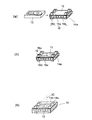
図1Aは、本発明の実施の形態1におけるハードディスクドライブ13(以下、HDD13と呼ぶ)の衝撃保護装置14が組み込まれているノートブック型パーソナルコンピュータ10(以下、ノートPC10と呼ぶ)の斜視図である。図1Bは、図1Aに示すHDD13と衝撃保護装置14の斜視図である。図1Cは、図1Aに示す衝撃保護装置14の斜視図である。図1Dは、図1Aに示す衝撃保護装置14の斜視図である。図2Aは、図1Dに示す衝撃保護装置14に用いられる緩衝部材16の斜視図である。図2Bは、図2Aに示す緩衝部材16の2B面における断面を示す断面図である。図2Cは、図1Dに示す衝撃保護装置14の2C面における断面を示す部分断面図である。
(Embodiment 1)
FIG. 1A is a perspective view of a notebook personal computer 10 (hereinafter referred to as a notebook PC 10) incorporating an
図1Aから図1Dに示すように、携帯情報機器であるノートPC10は、ノートPC本体11と表示部12とを有する。ノートPC本体11は、情報処理回路(図示せず)などを内部に有する携帯情報機器本体である。表示部12は、液晶パネル(図示せず)と液晶表示回路(図示せず)などを内部に有する。HDD13が、衝撃保護装置14で覆われて、ノートPC10の内部に収容されている。衝撃保護装置14は、内ケース14aと外ケース14bとを有する。
As shown in FIGS. 1A to 1D, a
内ケース14aは、包装材15と緩衝部材16とによって構成されている。包装材15は、薄い樹脂製のシート材からなる。包装材15は、シート材が裁断され、折り曲げ成型されて、内部に空間が形成されている。包装材15の内部の空間に、HDD13のような衝撃荷重に対して弱い装置、すなわち、衝撃荷重が緩衝される被衝撃保護装置が収容されている。包装材15には、略直方体の緩衝部材16が両面テープ(図示せず)によって貼付されている。このことによって、内ケース14aが構成されている。
The
緩衝部材16は、上面緩衝部材16uと下面緩衝部材16dと側面緩衝部材16sとを含む。それぞれ、上面緩衝部材16uは衝撃保護装置14の上面に配置され、下面緩衝部材16dは衝撃保護装置14の下面に配置され、側面緩衝部材16sは衝撃保護装置14の側面に配置されている。緩衝部材16は、押圧されると圧縮変形するクッション性能を有する柔軟材で構成されている。すなわち、緩衝部材16は弾性を有し、衝撃荷重を受けた際に収縮することによって、衝撃荷重を緩衝する。緩衝部材16は、好ましくは、発泡樹脂材、ゲル材、または、ゴム材料によって構成されている。緩衝部材16に発泡樹脂材が用いられる場合、発泡ポリウレタンなどが使用されと、衝撃緩衝性能、すなわち、弾性係数とダンパ定数の点から、好ましい。発泡ポリウレタンは、ノートPC10、または、自動車などに一般的に使用されている材料である。また、ゴム材料としては、衝撃吸収性能の高い特殊ゴムなどが用いられるとよい。
The
ここで、緩衝部材16に用いられる発泡体の体積の大型化によって、緩衝部材16の衝撃緩衝性能の向上が図られることが一般的に行われている。このため、緩衝部材16の重量が増加する傾向があり、高い衝撃緩衝性と小型・軽量化とは、通常、相反する特性である。
Here, it is generally performed that the shock absorbing performance of the
一般的に衝撃荷重の緩衝現象は、運動方程式(1)を用いて次のようにモデル化される。
mx″+cx′+kx=0 (1)
運動方程式(1)において、x″は物体の加速度、x′は物体の速度、xは物体の変位、mは物体の質量、cは粘性抵抗器の粘性減衰係数、kはバネ成分のバネ定数を表す。
In general, the shock absorbing shock phenomenon is modeled as follows using the equation of motion (1).
mx ″ + cx ′ + kx = 0 (1)
In the equation of motion (1), x ″ is the acceleration of the object, x ′ is the velocity of the object, x is the displacement of the object, m is the mass of the object, c is the viscous damping coefficient of the viscous resistor, and k is the spring constant of the spring component. Represents.
発泡樹脂などの発泡材を利用した緩衝部材16の場合、バネ成分と粘性抵抗器との両方の特性を有している。このため、用途に応じたバネ定数kと粘性減衰係数cを有する緩衝部材16が使用されることが望ましい。特に、粘性減衰係数cが高いほど、緩衝部材16が衝撃荷重を受けたときに、衝撃エネルギーが消費されやすい。
In the case of the cushioning
しかしながら、使用される用途に適した、最適のバネ定数kと粘性減衰係数cとを有する理想的な特性の発泡体を作成することは難しい。このことから、従来は、発泡体の体積と取り付け面積などの発泡体形状の調整が行われている。しかしながら、高い衝撃緩衝性能を発揮する発泡体形状を作成することは難しく、単純な円柱、または、直方体の組み合わせの形状などが採用される場合、十分な衝撃緩衝性能が発揮されない。 However, it is difficult to produce a foam with ideal characteristics suitable for the application used and having an optimal spring constant k and viscous damping coefficient c. For this reason, conventionally, the foam shape such as the volume and the mounting area of the foam has been adjusted. However, it is difficult to create a foam shape that exhibits high impact buffering performance, and when a simple cylinder or a combination of rectangular parallelepiped shapes is employed, sufficient impact buffering performance is not exhibited.
また、内ケース14aとHDD13とが、共に外ケース14bに収容されている。外ケース14bは、たとえば、アルミニウムなどの金属材料で構成された箱体状のケース部材である。なお、HDD13が内ケース14aと外ケース14bとに収容されることによって、衝撃保護装置14が構成されている。
The
このように構成された衝撃保護装置14は、衝撃荷重に対して弱いHDD13のような被衝撃保護装置を収容し、さらに、ノートPC本体11に実装されている。このことによって、落下などの非常に大きな衝撃荷重からHDD13が保護されている。さらに、日常動作などの小さな衝撃荷重、または、繰り返し加えられる振動力からHDD13が保護されている。
The
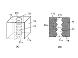
さらに、図2Aに示すように、緩衝部材16の一方の第1の平面17a(以下、平面17aと呼ぶ)に第1の開口部21a(以下、開口部21aと呼ぶ)が形成されている。さらに、平面17aに対向する、他方の第2の平面17b(以下、平面17bと呼ぶ)に第2の開口部21b(以下、開口部21bと呼ぶ)が形成されている。さらに、開口部21aと開口部21bとを貫通するようにして、中空の空洞部である空気貯蔵部22(以下、貯蔵部22と呼ぶ)が形成されている。貯蔵部22の内部には空気が蓄えられている。なお、貯蔵部22は、必ずしも開口部21aから開口部21bまで貫通する構成に限定されない。
Further, as shown in FIG. 2A, a
また、緩衝部材16の内部に、連続的につながった気泡(図示せず)である気孔が設けられているとよい。緩衝部材16が気孔を有することによって、気孔を通過して、貯蔵部22内に蓄えられている空気が、貯蔵部22の外へ流出することができる。
Moreover, it is good for the inside of the
なお、緩衝部材16は、圧縮変形する前の形状が、略直方体形状である。しかしながら、緩衝部材16は、円筒形状でもよい。さらに、緩衝部材16は、五角柱、六角柱などの多角形の断面形状などを有する、他の柱状形状でもよい。すなわち、緩衝部材16は、少なくとの一つの平面17aを有する立体形状であればよい。また、貯蔵部22が緩衝部材16を貫通して設けられている場合、緩衝部材16は、少なくとも一組の対向する平面17a、17bを有する立体形状であればよい。また、開口部21a、21bの形状は、図2Aに示すような円形形状以外に、緩衝部材16の形状に適応するように、三角形、または、四角形などの多角形、星形、十字形などでもよい。
The
平面17bが、両面テープを用いて包装材15に貼り付けられることによって、貯蔵部22を構成する一方の開口部21bは包装材15の面と密着し、貯蔵部22が塞がれる。このとき、外ケース14bと平面17aとは密着して当接している。しかしながら、外ケース14bと平面17aとは密封固定は、されていない。
By attaching the
以下、本発明の緩衝部材16の一例として、下面緩衝部材16dに関して、HDD13に対する衝撃保護装置14の緩衝動作について、図3Aから図3Cを用いて説明する。
Hereinafter, as an example of the shock-absorbing
図3Aから図3Cは、HDD13を収容した衝撃保護装置14に対して、下方から大きな衝撃荷重が加えられたときの緩衝動作を説明する説明図である。衝撃保護装置14に大きな衝撃荷重が加えられるときとは、たとえば、ユーザが誤ってノートPC10を落下させたときなどである。
3A to 3C are explanatory views for explaining a buffering operation when a large impact load is applied from below to the
図3Aに示すように、まず、下方(矢印31方向)から外ケース14bを介してHDD13に衝撃荷重が加えられる。HDD13の重さに応じて、図3Bに示すように、下面緩衝部材16dは衝撃方向(矢印32方向)に圧縮変形される。このとき、貯蔵部22も圧縮変形され、貯蔵部22内の空気が圧縮される。このことによって、貯蔵部22の内部の空気圧の圧力が上昇する。
As shown in FIG. 3A, first, an impact load is applied to the
貯蔵部22の内部の空気圧の圧力が上昇することによって、平面17aが変形し、密着して当接している外ケース14bと平面17aとの間の当接部に隙間24が形成される。なお、貯蔵部22の内部の空気圧の圧力上昇の大きさは、平面17aと外ケース14bとの間の隙間24の気密性と下面緩衝部材16dの素材通気性とに依存する。すなわち、貯蔵部22の内部の空気圧の圧力上昇の結果、圧力の増加した空気の一部が、矢印41aに沿って、隙間24を通過して貯蔵部22から貯蔵部22の外へと流出する。また、圧力の増加した空気の一部が、矢印42aに沿って、下面緩衝部材16dの気孔を通過して貯蔵部22の外に流出する。このとき、気体の流れ(矢印41a、42a)に対する粘性抵抗が生じる。このことによって、下面緩衝部材16dの圧縮変形が妨げられ、HDD13へ加えられる衝撃エネルギーが吸収される。
When the pressure of the air pressure inside the
つまり、下面緩衝部材16dが圧縮変形する際に、空気の流出する粘性抵抗によって、下面緩衝部材16dの圧縮変形が妨げられる。このようにして、下面緩衝部材16dは衝撃荷重を受け、下面緩衝部材16dの粘性抵抗によって、衝撃エネルギーが消費される。この結果、下面緩衝部材16dの衝撃緩衝効果が向上する。一般に、粘性抵抗器は、空気の流出する速度が高いほど衝撃エネルギーを消費する。すなわち、下面緩衝部材16dに粘性抵抗器が設けられることによって、下面緩衝部材16dに衝撃荷重が加えられる初期段階の、高い空気流出速度が利用されて、高い衝撃エネルギー消費効果と高い衝撃緩衝効果とが得られる。
That is, when the lower-
下面緩衝部材16dは、衝撃荷重を吸収した後、図3Cに示すように、下面緩衝部材16dの元々の材料特性の持つ復元力によって、矢印33で示す方向に膨らみ、下面緩衝部材16dは衝撃荷重を受ける前の状態に復元する。なお、下面緩衝部材16dの形状が元の状態に復元する際に、減圧された貯蔵部22中に向かって、矢印41bに沿って、隙間24を通過して空気が流入する。同様に、下面緩衝部材16dの気孔を通過して、矢印42bに沿って、貯蔵部22へ空気が流入する。なお、下面緩衝部材16dの復元は、衝撃荷重を受けるときに比べて緩やかに、ゆっくりと復元する。
After absorbing the impact load, the lower
図4は、外ケース14bに加わる衝撃荷重によって、HDD13が受ける衝撃荷重の大きさを測定した測定データを示すグラフである。
FIG. 4 is a graph showing measurement data obtained by measuring the magnitude of the impact load received by the
図4に示す測定結果は、発泡体が緩衝部材16として使用された場合の測定データを示す。図4は、緩衝部材16が用いられた場合と従来の緩衝部材が用いられた場合とに、外ケース14bに対して、同じ衝撃荷重が加えられたときの、HDDに加えられる衝撃荷重の測定データを示す。図4に示すように、緩衝部材16が用いられた場合は、従来の緩衝部材が用いられた場合に比べ、HDD13へ加わる衝撃荷重が小さく抑えられている。すなわち、本発明の緩衝部材16が用いられた場合、従来の緩衝部材が用いられた場合に比較して、HDD13に加わる衝撃荷重が30%程度抑制される。このように、本発明における緩衝部材16による緩衝性能は、従来の緩衝部材に比較して、非常に優れた緩衝効果が得られる。
The measurement result shown in FIG. 4 shows measurement data when the foam is used as the
以上のように、実施の形態1によれば、本発明の衝撃保護装置14は、衝撃保護装置14を構成する緩衝部材16に、貯蔵部22が設けられている。このことによって、貯蔵部22内の空気の流出によって、衝撃エネルギーの消費が促進され、緩衝部材16自体に粘性抵抗器の機能が付与される。このことによって、高い衝撃緩衝効果を有する緩衝部材16と衝撃保護装置14とが実現される。したがって、部品点数が少なく、コストダウンが図られると同時に、簡単な構造の緩衝部材16と衝撃保護装置14とが実現される。このため、組立て製造などの量産も簡易化される衝撃保護装置14が実現される。さらに、衝撃保護装置14の小型・軽量化にも寄与するため、小型・軽量が求められるノートPC10などの携帯情報機器への応用に適した緩衝部材16と衝撃保護装置14とが提供される。
As described above, according to the first embodiment, in the
なお、図3Aから図3Cにおいて、緩衝部材16として、下面緩衝部材16dを例として説明した。しかしながら、HDD13に対する上面からの衝撃荷重、または、側面からの衝撃荷重に備えて、上面緩衝部材16uと側面緩衝部材16sとに本発明が適応されても同様の作用と効果とが得られる。
In FIG. 3A to FIG. 3C, the lower
また、貯蔵部22の内部の圧縮空気は、緩衝部材16の部材自体が元々有する細かい気孔を通して流出するとして説明した。しかしながら、気孔は、細い針、または、針状治工具などを用いて、貯蔵部22の内側壁面から緩衝部材16の外側壁面まで貫通する複数の貫通孔を人為的に形成されてもよい。この場合、壁面に対して、均一に貫通孔が形成されることが好ましい。
Further, it has been described that the compressed air inside the
また、緩衝部材16の形状は、たとえば、幅L1=20mm、高さL2=15mm、奥行きL3=15の形状が好ましく、開口部21aの直径はD0=6mmが好ましい。すなわち、緩衝部材16の体積に対する、貯蔵部22の容積比率は、9.4%程度である。さらに、緩衝部材16に用いられる材料特性は、硬度として、たとえば、50%圧縮時の反発力が11.3kPaが好ましく、気泡率(気孔の割合)として、空気/材料=94/6が好ましい。なお、緩衝部材16の形状、材料特性は、上記した構成に限定されない。
The shape of the
(実施の形態2)
図5A〜図8Fは、本発明の実施の形態2におけるHDD13の衝撃保護装置14に用いられる、別の態様の緩衝部材16を示す。
(Embodiment 2)
5A to 8F show another aspect of the
図5Aは、図1Dに示す衝撃保護装置14に用いられる別の態様の緩衝部材16の斜視図である。図5Bは、図5Aに示す緩衝部材16の5B面における断面を示す断面図である。さらに、図6Aは、図1Dに示す衝撃保護装置14に用いられる、さらに別の態様の緩衝部材16の斜視図である。図6Bは、図6Aに示す緩衝部材16の6B面における断面を示す断面図である。さらにまた、図7Aは、図1Dに示す衝撃保護装置14に用いられる、さらに別の態様の緩衝部材16の斜視図である。図7Bは、図7Aに示す緩衝部材16の7B面における断面を示す断面図である。図8A〜図8Fは、同様に、図1Dに示す衝撃保護装置14に用いられる、さらに別の態様の緩衝部材16の斜視図である。また、図9Aは、図1Dに示す衝撃保護装置14に用いられる、さらに別の態様の緩衝部材16の斜視図である。図9Bは、図1Dに示す衝撃保護装置14に用いられる、さらに別の態様の緩衝部材16の平面図である。
FIG. 5A is a perspective view of another embodiment of the
図5Aと図5Bとに示す緩衝部材16は、図2Aに示す緩衝部材16とは異なり、貯蔵部22は、平面17aに開口する開口部21aを有しているが、平面17bに開口する開口部21bを有していない。すなわち、貯蔵部22は、必ずしも平面17a側の開口部21aから平面17bまで貫通しなくてもよい。したがって、緩衝部材16は、一つの開口部21aを有する平面17aが外ケース14bに当接して構成され、開口部の設けられていない反対側の平面17bが両面テープによって包装材15に貼り付けられて、内ケース14aを構成しても、同様の作用と効果とが得られる。すなわち、緩衝部材16の形状は、少なくとの一つの平面17aを有する立体形状であればよい。
The
また、緩衝部材16は、図6A〜図7Bに示すような空洞形状と内側壁面22a形状とを有する貯蔵部22を有していてもよい。図6A〜図7Bに示すように、貯蔵部22の内側壁面22aは、一様でないランダムな凹凸が形成され、凹凸の度合い(山−谷の高度差)、凹凸の数が種々調整されることによって、緩衝部材16の粘性抵抗が容易に可変される。緩衝部材16の粘性抵抗が可変される場合、選択される粘性抵抗の特性に起因して、緩衝部材16の緩衝性能、または、耐久性などのさらなる向上が期待される。
Moreover, the
さらに、図8A〜図8Eに示すように、貯蔵部22の断面形状と開口部21a、21bの形状は、円形以外に三角形、四角形、六角形などの多角形、星形、十字形でもよい。なお、貯蔵部22の断面形状と開口部21a、21bの形状は必ずしも相似形に限らない。たとえば、図示しないが、貯蔵部22の断面形状が四角形であって、開口部21a、21bの形状が円形であってもよい。
Further, as shown in FIGS. 8A to 8E, the cross-sectional shape of the
また、緩衝部材16は、圧縮変形する前の形状は略直方体形状の柔軟材であるとして説明した。しかしながら、図8Fに示すように、緩衝部材16の外形形状は円筒形状でもよい。また、図示しないが、緩衝部材16の外形形状は他の柱状形状でもよい。緩衝部材16の形状に対応して、貯蔵部22の断面形状、または、開口部21a、21bの形状が円形、多角形、星形でもよい。
Further, the
また、図9Aに示すように、緩衝部材16は、複数の貯蔵部22が形成されてもよい。複数の貯蔵部22が緩衝部材16に形成される場合、それぞれの隣接する貯蔵部22の間の距離は、均等であることが好ましい。さらに、図9Bに示すように、複数の貯蔵部22が緩衝部材16に形成される場合、複数のそれぞれ隣接する貯蔵部22の開口部21a、21bの中心間距離Lが、それぞれ均等であることが好ましい。このように、複数の貯蔵部22が均等に緩衝部材16に形成されることによって、緩衝部材16が受ける衝撃荷重が、緩衝部材16の平面17aに亘って均等に働く。このことによって、衝撃エネルギーの吸収が滑らかに行われる。
Moreover, as shown to FIG. 9A, the
(実施の形態3)
図10Aは、本発明の実施の形態3におけるHDD13の衝撃保護装置14に用いられる緩衝部材16の斜視図である。図10Bは、図10Aに示す緩衝部材16の10B面における断面を示す断面図である。図10Cは、図1Dに示す衝撃保護装置14に、図10Aに示す緩衝部材16が用いられ、衝撃荷重を受ける場合の緩衝部材16の断面図を示す。図11Aは、本発明の実施の形態3におけるHDD13の衝撃保護装置14に用いられる他の態様の緩衝部材16の斜視図である。図11Bは、図11Aに示す緩衝部材16の11B面における断面を示す断面図である。図11Cは、図1Dに示す衝撃保護装置14に、図11Aに示す緩衝部材16が用いられ、衝撃荷重を受ける場合の緩衝部材16の断面図を示す。
(Embodiment 3)
FIG. 10A is a perspective view of
図10Aと図10Bとに示すように、蓋部26は、緩衝部材16の開口部21aを覆うように配置されている。蓋部26は、好ましくは、シート状の樹脂によって構成されている。蓋部26の取り付けは、たとえば、両面テープ(図示せず)が使用されることによって容易に行われる。なお、蓋部26が緩衝部材16に貼り付けられるとき、開口部21aが両面テープで完全に密封されるのでなく、貯蔵部22の空気が流出できる程度の、さらに、蓋部26にずれが生じない程度の固定力で貼り付けられることが好ましい。
As shown in FIGS. 10A and 10B, the
また、外ケース14bは、アルミニウムなどの金属材料で構成された箱体状のケース部材である。したがって、外ケース14bが成型される時の加工の状態によって、外ケース14bの表面14cは、仕上がり状態は常に一様ではない。このことによって、緩衝部材16と外ケース14bとの当接状態は常に安定しているとは限らない。しかしながら、蓋部26が設けられることによって、平面17aに蓋部26が密着し、開口部21aの密閉性が高められる。このことによって、緩衝部材16に付与される粘性抵抗器としての機能が安定して発揮される。
The
以下、本発明の実施の形態3における緩衝部材16と衝撃保護装置14との緩衝動作について、図10Cを用いて説明する。
Hereinafter, the buffering operation of the
外ケース14bを介して緩衝部材16に衝撃荷重が加わると、緩衝部材16と貯蔵部22とが圧縮変形される。貯蔵部22内の圧縮された空気の一部は、貯蔵部22の開口部21aと緩衝部材16に当接している蓋部26との間の隙間24から貯蔵部22の外に流出する。
When an impact load is applied to the
本実施の形態3では、蓋部26が緩衝部材16の開口部21aと外ケース14bとの間に挿入されている。このため、緩衝部材16と蓋部26との当接状態が一定に保たれている。このことによって、成型時における外ケース14bの仕上がり状態に関係なく、貯蔵部22内の圧縮された空気の流れに対する粘性抵抗が一定に保たれる。この結果、緩衝部材16と衝撃保護装置14とは、安定した緩衝性能を有する。
In the third embodiment, the
また、蓋部26は、開口部21aを完全に覆う必要はなく、また、開口部21aに密着して配置される必要もない。すなわち、開口部21aは、蓋部26と両面テープとが用いられて、開口部21aの密封度合い、つまり、蓋部26が故意にズラされ、または、両面テープ量、配置が可変されることによって、緩衝部材16の粘性抵抗器としての特性が調節可能である。
Moreover, the
以上のように、本実施の形態3によれば、貯蔵部22を有する緩衝部材16に対して、開口部21aを覆う蓋部26が設けられている。このことによって、衝撃荷重を受ける時に、緩衝部材16の粘性抵抗が一定に保たれて、安定した緩衝性能が得られる。さらに、緩衝部材16の粘性抵抗器としての特性が容易に調節される。
As described above, according to the third embodiment, the
なお、蓋部26は通気性を有していてもよい。また、蓋部26を貫通する穴部を有していてもよい。さらには、蓋部26の素材は緩衝部材16と異なる特性を有する発泡体でもよい。
In addition, the
また、蓋部26は、図10Aに示す緩衝部材16のような、円筒形状の貯蔵部22を有する略直方体形状の緩衝部材16にだけ適応されるのではなく、上述の様々な態様の緩衝部材16に適応可能である。
Moreover, the
また、図9Aと図9Bとに示すように、複数の貯蔵部22が形成された緩衝部材16に対しては、蓋部26が全ての開口部21aを覆ってもよい。また、蓋部26を構成するシート材が適宜裁断されて、開口部21aが選択的に覆われる構成であれば、緩衝部材16の粘性抵抗の調節範囲がさらに拡大される。
Moreover, as shown to FIG. 9A and FIG. 9B, with respect to the
また、図11Aに示すように、蓋部26aは、開口部21aに対応する位置に開口部26bを有していてもよい。蓋部26aが開口部26bを有する場合、両面テープなど(図示せず)を用いて、蓋部26aの全面が緩衝部材16に、貼り付けられ、蓋部26aによって、緩衝部材16の第1の平面17aが構成される。緩衝部材16が、図11Aと図11Bとに示すような構成を有する場合、緩衝部材16が衝撃荷重を受けると、図11Cに示すように、蓋部26aと外ケース14bとの間に隙間24が形成される。なお、厚みと硬度、表面粗さなどの蓋部26aの特性が調節されことによって、圧縮空気の流れに対する緩衝部材16の粘性抵抗器としての特性が容易に調節される。
Moreover, as shown to FIG. 11A, the
(実施の形態4)
図12Aは、本発明の実施の形態4におけるHDD13の衝撃保護装置14に用いられる緩衝部材16の斜視図である。図12Bは、図12Aに示す緩衝部材16の12B面における断面を示す断面図である。図12Cは、図1Dに示す衝撃保護装置14に、図12Aに示す緩衝部材16が用いられ、衝撃荷重を受ける場合の緩衝部材16の断面図を示す。
(Embodiment 4)
FIG. 12A is a perspective view of
切欠部28は、平面17aに設けられている。切欠部28は、緩衝部材16の開口部21aに隣接する貯蔵部22の内側壁面22aから緩衝部材16の外側壁面16aに向かうにしたがって、空間が狭くなる。切欠部28の断面形状は、くさび形状であり、断面12B面に対して、直角をなす切断面における切欠部28の断面形状は略長方形である。
The
また、外ケース14bは、アルミニウムなどの金属材料で構成された箱体状のケース部材である。したがって、外ケース14bが成型される時の加工の状態によって、外ケース14bの表面14cの仕上がり状態は常に一様ではない。このことによって、緩衝部材16と外ケース14bとの当接状態は常に安定しているとは限らない。しかしながら、切欠部28が設けられることによって、緩衝部材16が衝撃荷重を受けて、貯蔵部22内の空気の圧力が高くなった場合に、空気が切欠部28に案内されて、圧縮された空気の流路が常に安定化される。
The
以下、本発明の実施の形態4における緩衝部材16と衝撃保護装置14との緩衝動作について、図12Cを用いて説明する。
Hereinafter, the buffering operation of the
外ケース14bを介して緩衝部材16に衝撃荷重が加わると、緩衝部材16、貯蔵部22とが圧縮変形される。貯蔵部22内の圧縮された空気の一部は、貯蔵部22の開口部21aと緩衝部材16に当接している外ケース14bとの隙間24から貯蔵部22の外に流出する。
When an impact load is applied to the
本実施の形態4では、緩衝部材16の開口部21aの付近に切欠部28が形成されている。このことによって、貯蔵部22内の圧縮された空気の一部が、切欠部28の開口部29に導かれ、圧縮空気の流路が確保される。すなわち、切欠部28は、空気の流れを安定化する働きを有する。開口部29に導かれた圧縮空気の一部は、切欠部28と外ケース14bとの空間を通り、さらに、切欠部28が形成されていない部分から先は、幅の短い隙間24を通って貯蔵部22の外に流出する。なお、隙間24は、圧縮空気の圧力によって、緩衝部材16が変形して形成される。このような構成によって、貯蔵部22内の圧縮された空気の流れに対する粘性抵抗は、外ケース14bの表面14cの仕上がり状態に関係なく、一定に保たれる。この結果、緩衝部材16と衝撃保護装置14とは、安定した緩衝性能を有する。
In the fourth embodiment, a
緩衝部材16は、衝撃荷重を吸収した後、緩衝部材16の元々の材料特性の持つ復元力によって、衝撃荷重を受ける前の状態に復元する。緩衝部材16の形状が元の状態に復元する際に、減圧された貯蔵部22内に、隙間24を通過して、空気が流入する。同様に、緩衝部材16の気孔を通過して、貯蔵部22へ空気が流入する。なお、緩衝部材16の復元は、衝撃荷重を受けるときに比べて緩やかに、ゆっくりと復元する。貯蔵部22内に、隙間24を通過して、空気が流入するとき、切欠部28が弁の役割を果たす。このことによって、流出経路とは異なる経路で空気は流入し、緩衝部材16は、衝撃荷重を受けるときに比べ、緩やかに復元する。
After absorbing the impact load, the
また、切欠部28の切欠幅Wと切欠長Vと切欠高さHとが調節されことによって、圧縮空気の流れに対する緩衝部材16の粘性抵抗器としての特性が容易に調節される。
Further, by adjusting the notch width W, the notch length V, and the notch height H of the
以上のように、本実施の形態4によれば、貯蔵部22を有する緩衝部材16が、貯蔵部22の開口部21a付近に形成されて切欠部28を有する。このことによって、衝撃荷重を受けるときに、緩衝部材16の粘性抵抗が一定に保たれ、安定した衝撃緩衝性能が得られる。さらに、緩衝部材16の粘性抵抗器としての特性が容易に調節される。
As described above, according to the fourth embodiment, the
本発明にかかる緩衝部材は、空気貯蔵部内の空気の流出により衝撃エネルギーの消費を促し、緩衝部材自体に粘性抵抗器の役割を持たせることで高い緩衝効果を有し、ハードディスクドライブが搭載された携帯情報機器の落下時の衝撃からハードディスクドライブを保護する緩衝部材等として有用である。 The shock-absorbing member according to the present invention promotes the consumption of impact energy by the outflow of air in the air storage section, and has a high shock-absorbing effect by giving the shock-absorbing member the role of a viscous resistor, and the hard disk drive is mounted. It is useful as a shock-absorbing member that protects the hard disk drive from impact when the portable information device is dropped.
10 ノートPC
12 表示部
13 ハードディスクドライブ(HDD)
14 衝撃保護装置
15 包装材
16 緩衝部材
17 平面
21 開口部
22 空気貯蔵部
10 Notebook PC
12
DESCRIPTION OF
Claims (5)
前記緩衝部材の第1の平面に形成した少なくとも1つの開口部からその緩衝部材の内部に少なくとも1つの空気貯蔵部を形成し、
前記緩衝部材の前記第1の平面と対向する第2の平面を前記被衝撃保護装置を収容した収容体に密着固定するとともに、前記第1の平面を前記ケースに当接し、
前記ケースが受けた衝撃により前記緩衝部材の圧縮変形とともに前記空気貯蔵部内の空気が圧縮され、当該圧縮空気圧の上昇により前記第1の平面が変形して前記ケースとその第1の平面との間に隙間が形成され、前記空気貯蔵部内の圧縮空気が前記隙間から流出することにより前記衝撃による前記緩衝部材の圧縮変形が妨げられるようにしたことを特徴とする緩衝保護装置。 A shock-protecting device that houses a shock-protecting device housed in a container together with a shock-absorbing member having elasticity,
Forming at least one air reservoir in the buffer member from at least one opening formed in the first plane of the buffer member;
A second plane opposite to the first plane of the cushioning member is tightly fixed to a container housing the impacted protection device, and the first plane is in contact with the case;
Due to the impact received by the case, the air in the air storage section is compressed together with the compression deformation of the buffer member, and the first plane is deformed by the increase of the compression air pressure, so that the case and the first plane are between. A shock-absorbing protection device according to claim 1, wherein a gap is formed in the air-storing part, and compressed air in the air storage part flows out of the gap to prevent compressive deformation of the shock-absorbing member due to the impact.
前記緩衝部材の第1の平面に形成した少なくとも1つの開口部からその緩衝部材の内部に少なくとも1つの空気貯蔵部を形成し、
前記緩衝部材の前記第1の平面と対向する第2の平面を前記被衝撃保護装置を収容した収容体に密着固定するとともに、前記第1の平面を前記ケースに取り付けられたシート状部材に当接し、
前記ケースが受けた衝撃により前記緩衝部材の圧縮変形とともに前記空気貯蔵部内の空気が圧縮され、当該圧縮空気圧の上昇により前記第1の平面が変形して前記シート状部材とその第1の平面との間に隙間が形成され、前記空気貯蔵部内の圧縮空気が前記隙間から流出することにより前記衝撃による前記緩衝部材の圧縮変形が妨げられるようにしたことを特徴とする緩衝保護装置。 A shock-protecting device that houses a shock-protecting device housed in a container together with a shock-absorbing member having elasticity,
Forming at least one air reservoir in the buffer member from at least one opening formed in the first plane of the buffer member;
A second flat surface of the buffer member facing the first flat surface is closely fixed to a container housing the impact protection device, and the first flat surface is contacted with a sheet-like member attached to the case. contact,
Due to the impact received by the case, the air in the air storage part is compressed together with the compression deformation of the buffer member, and the first plane is deformed by the increase of the compression air pressure, and the sheet-like member and the first plane A shock-absorbing protection device, wherein a gap is formed between the shock-absorbing member and the compressed air in the air storage part flows out of the gap to prevent the shock-absorbing member from being compressed and deformed by the impact.
Priority Applications (1)
| Application Number | Priority Date | Filing Date | Title |
|---|---|---|---|
| JP2007257297A JP5076790B2 (en) | 2006-12-20 | 2007-10-01 | Shock protection device |
Applications Claiming Priority (5)
| Application Number | Priority Date | Filing Date | Title |
|---|---|---|---|
| JP2006342163 | 2006-12-20 | ||
| JP2006342163 | 2006-12-20 | ||
| JP2007113723 | 2007-04-24 | ||
| JP2007113723 | 2007-04-24 | ||
| JP2007257297A JP5076790B2 (en) | 2006-12-20 | 2007-10-01 | Shock protection device |
Publications (3)
| Publication Number | Publication Date |
|---|---|
| JP2008291987A JP2008291987A (en) | 2008-12-04 |
| JP2008291987A5 JP2008291987A5 (en) | 2010-08-26 |
| JP5076790B2 true JP5076790B2 (en) | 2012-11-21 |
Family
ID=39542410
Family Applications (1)
| Application Number | Title | Priority Date | Filing Date |
|---|---|---|---|
| JP2007257297A Expired - Fee Related JP5076790B2 (en) | 2006-12-20 | 2007-10-01 | Shock protection device |
Country Status (2)
| Country | Link |
|---|---|
| US (1) | US8302928B2 (en) |
| JP (1) | JP5076790B2 (en) |
Families Citing this family (8)
| Publication number | Priority date | Publication date | Assignee | Title |
|---|---|---|---|---|
| JP2006190375A (en) * | 2005-01-05 | 2006-07-20 | Hitachi Global Storage Technologies Netherlands Bv | Magnetic disk drive |
| US7684183B2 (en) * | 2007-03-29 | 2010-03-23 | Panasonic Corporation | Impact buffer, impact buffering device, and information processor having impact buffering device |
| WO2013184148A1 (en) * | 2012-06-08 | 2013-12-12 | Apple Inc. | Mass storage device with elastomeric material and related portable computing device and method |
| JP6120221B2 (en) * | 2012-08-30 | 2017-04-26 | パナソニックIpマネジメント株式会社 | Electronics |
| JP6064256B2 (en) * | 2012-08-30 | 2017-01-25 | パナソニックIpマネジメント株式会社 | Electronic equipment and cushioning materials |
| US9099163B1 (en) * | 2013-03-14 | 2015-08-04 | Western Digital Technologies, Inc. | Hard disk drive (HDD) mounting system for shock and vibration |
| KR102361638B1 (en) * | 2015-08-25 | 2022-02-10 | 삼성전자주식회사 | Solid state drive apparatus |
| CN107448749A (en) * | 2017-08-03 | 2017-12-08 | 合肥祥国电子商务有限公司 | A kind of airbag restraint formula computer display stand device |
Family Cites Families (27)
| Publication number | Priority date | Publication date | Assignee | Title |
|---|---|---|---|---|
| GB1119445A (en) * | 1965-03-26 | 1968-07-10 | Danavox Internat A S | Hearing aid |
| US4611782A (en) * | 1984-06-08 | 1986-09-16 | Bridgestone Corporation | Vibration isolating apparatus |
| JPH0136697Y2 (en) * | 1985-07-10 | 1989-11-07 | ||
| US4901486A (en) * | 1987-03-06 | 1990-02-20 | Kajima Corporation | Elasto-plastic damper |
| JPH0423826Y2 (en) | 1987-04-16 | 1992-06-03 | ||
| JPH01206133A (en) * | 1988-02-12 | 1989-08-18 | Bridgestone Corp | Vibro-isolator |
| DE3901897A1 (en) * | 1989-01-23 | 1990-07-26 | Wolf Woco & Co Franz J | RUBBER SPRING ELEMENT |
| US5201489A (en) * | 1989-01-23 | 1993-04-13 | Woco Franz-Josef Wolf & Co. | Surface bearing and method for its production |
| JP2858181B2 (en) * | 1991-01-21 | 1999-02-17 | 横浜ゴム株式会社 | Energy absorbing structure |
| JPH05319347A (en) | 1992-05-21 | 1993-12-03 | Bridgestone Cycle Co | Shock absorber for bicycle frame |
| US5370411A (en) * | 1991-10-14 | 1994-12-06 | Bridgestone Cycle Co., Ltd. | Bicycle frame assembly |
| US6024338A (en) * | 1994-03-11 | 2000-02-15 | Nissan Motor Co., Ltd. | Vibration insulating pad |
| JPH08334140A (en) * | 1995-06-08 | 1996-12-17 | Alpine Electron Inc | Elastic support device for vehecular loading equipment |
| JPH10141408A (en) | 1996-11-12 | 1998-05-29 | Polyurethan Kasei Kk | Buffer body |
| US6138980A (en) * | 1999-06-24 | 2000-10-31 | Lord Corporation | Pilot mounting |
| US6830793B2 (en) * | 1999-09-27 | 2004-12-14 | The Aerospace Corporation | Composite damping material |
| US6320122B1 (en) * | 1999-10-12 | 2001-11-20 | Hewlett Packard Company | Electromagnetic interference gasket |
| JP2003022075A (en) * | 2001-07-05 | 2003-01-24 | Toshiba Corp | Electronic apparatus |
| US6621000B2 (en) * | 2001-08-21 | 2003-09-16 | Dell Products L.P. | Perforated EMI gasket |
| US6543741B1 (en) * | 2001-12-26 | 2003-04-08 | Carrier Corporation | Vibration isolation for a transversely mounted compressor |
| JP2003316473A (en) * | 2002-04-25 | 2003-11-07 | Matsushita Electric Ind Co Ltd | Portable information processing device |
| AU2003254828A1 (en) * | 2002-10-31 | 2004-05-25 | Kyoraku Co., Ltd. | Impact absorbing body for vehicle |
| KR100565588B1 (en) * | 2003-02-28 | 2006-03-29 | 엘지전자 주식회사 | Structure for mounting compressor of refrigerator |
| JP2004322945A (en) * | 2003-04-28 | 2004-11-18 | Ohtsuka Poly-Tech Co Ltd | Damper for saddle |
| JP4069876B2 (en) * | 2004-02-03 | 2008-04-02 | ソニー株式会社 | Hard disk drive storage device and electronic device |
| JP2005256982A (en) * | 2004-03-12 | 2005-09-22 | Matsushita Electric Ind Co Ltd | Shock absorber |
| US7684183B2 (en) * | 2007-03-29 | 2010-03-23 | Panasonic Corporation | Impact buffer, impact buffering device, and information processor having impact buffering device |
-
2007
- 2007-10-01 JP JP2007257297A patent/JP5076790B2/en not_active Expired - Fee Related
- 2007-10-29 US US11/926,496 patent/US8302928B2/en active Active
Also Published As
| Publication number | Publication date |
|---|---|
| US20080151421A1 (en) | 2008-06-26 |
| US8302928B2 (en) | 2012-11-06 |
| JP2008291987A (en) | 2008-12-04 |
Similar Documents
| Publication | Publication Date | Title |
|---|---|---|
| JP5076790B2 (en) | Shock protection device | |
| US7471509B1 (en) | Shock protection for disk drive embedded in an enclosure | |
| US7486509B2 (en) | Bracket for disk drive | |
| US6567265B1 (en) | Apparatus having flexible mounting mechanism | |
| US6809916B2 (en) | Shock absorbing member capable of absorbing larger impact applied to electronic apparatus | |
| US6556383B2 (en) | Disc drive anti-shock suspension cushions | |
| JPH10222972A (en) | Storage device and impact resistant accommodation container to be used therefor | |
| US20030174464A1 (en) | Information storage device | |
| US7684183B2 (en) | Impact buffer, impact buffering device, and information processor having impact buffering device | |
| JP5125343B2 (en) | Shock absorber, impact protection device for hard disk drive, and portable information device using the same | |
| KR100772690B1 (en) | Buffer for disk drive and disk drive assembly having the same | |
| US9165607B2 (en) | Mounting structure for component of electronic device | |
| US7395931B2 (en) | Protective device for reducing the impact of physical shock | |
| US20140063727A1 (en) | Electronic apparatus and buffer material | |
| US8702073B2 (en) | Shock absorber capable of damping vibration | |
| US7345845B2 (en) | Fluid damping structure for hard disk drives and vibration sensitive electronic devices | |
| JP2005018835A (en) | Buffer member for external storage device | |
| JP4376567B2 (en) | Buffer member for external storage device | |
| JP6024978B2 (en) | Electronic equipment and electronic parts storage case | |
| JP2000156569A (en) | Shock absorbing structure of electronic apparatus | |
| JP4900182B2 (en) | Shock absorber and information processing apparatus having the shock absorber | |
| JP2008282505A (en) | Buffer method for magnetic disk device, shock buffer method, and electronic equipment | |
| JP2003297068A (en) | Cartridge for magnetic recording and reproducing apparatus, and information processor employing the same | |
| JP4169148B2 (en) | Buffer member mounting structure | |
| KR100634418B1 (en) | Bracket for disk drive |
Legal Events
| Date | Code | Title | Description |
|---|---|---|---|
| A521 | Request for written amendment filed |
Free format text: JAPANESE INTERMEDIATE CODE: A523 Effective date: 20100713 |
|
| A621 | Written request for application examination |
Free format text: JAPANESE INTERMEDIATE CODE: A621 Effective date: 20100713 |
|
| RD01 | Notification of change of attorney |
Free format text: JAPANESE INTERMEDIATE CODE: A7421 Effective date: 20100806 |
|
| A977 | Report on retrieval |
Free format text: JAPANESE INTERMEDIATE CODE: A971007 Effective date: 20110810 |
|
| A131 | Notification of reasons for refusal |
Free format text: JAPANESE INTERMEDIATE CODE: A131 Effective date: 20120131 |
|
| A521 | Request for written amendment filed |
Free format text: JAPANESE INTERMEDIATE CODE: A523 Effective date: 20120315 |
|
| TRDD | Decision of grant or rejection written | ||
| A01 | Written decision to grant a patent or to grant a registration (utility model) |
Free format text: JAPANESE INTERMEDIATE CODE: A01 Effective date: 20120731 |
|
| A01 | Written decision to grant a patent or to grant a registration (utility model) |
Free format text: JAPANESE INTERMEDIATE CODE: A01 |
|
| A61 | First payment of annual fees (during grant procedure) |
Free format text: JAPANESE INTERMEDIATE CODE: A61 Effective date: 20120813 |
|
| FPAY | Renewal fee payment (event date is renewal date of database) |
Free format text: PAYMENT UNTIL: 20150907 Year of fee payment: 3 |
|
| R151 | Written notification of patent or utility model registration |
Ref document number: 5076790 Country of ref document: JP Free format text: JAPANESE INTERMEDIATE CODE: R151 |
|
| FPAY | Renewal fee payment (event date is renewal date of database) |
Free format text: PAYMENT UNTIL: 20150907 Year of fee payment: 3 |
|
| LAPS | Cancellation because of no payment of annual fees |