JP6063676B2 - Imaging device - Google Patents

Imaging device Download PDF

Info

Publication number
JP6063676B2
JP6063676B2 JP2012195506A JP2012195506A JP6063676B2 JP 6063676 B2 JP6063676 B2 JP 6063676B2 JP 2012195506 A JP2012195506 A JP 2012195506A JP 2012195506 A JP2012195506 A JP 2012195506A JP 6063676 B2 JP6063676 B2 JP 6063676B2
Authority
JP
Japan
Prior art keywords
image sensor
optical axis
main body
image
housing
Prior art date
Legal status (The legal status is an assumption and is not a legal conclusion. Google has not performed a legal analysis and makes no representation as to the accuracy of the status listed.)
Active
Application number
JP2012195506A
Other languages
Japanese (ja)
Other versions
JP2014052438A (en
Inventor
長岡 弘仁
弘仁 長岡
哲也 高木
哲也 高木
Current Assignee (The listed assignees may be inaccurate. Google has not performed a legal analysis and makes no representation or warranty as to the accuracy of the list.)
Olympus Corp
Original Assignee
Olympus Corp
Priority date (The priority date is an assumption and is not a legal conclusion. Google has not performed a legal analysis and makes no representation as to the accuracy of the date listed.)
Filing date
Publication date
Application filed by Olympus Corp filed Critical Olympus Corp
Priority to JP2012195506A priority Critical patent/JP6063676B2/en
Publication of JP2014052438A publication Critical patent/JP2014052438A/en
Application granted granted Critical
Publication of JP6063676B2 publication Critical patent/JP6063676B2/en
Active legal-status Critical Current
Anticipated expiration legal-status Critical

Links

Images

Description

本発明は、鏡枠本体部に対して撮像素子を所定の位置に保持する撮像素子保持部を備えた撮像装置に関する。 The present invention relates to an imaging apparatus including an imaging element holding unit that holds an imaging element at a predetermined position with respect to a lens barrel main body .

カメラ等の撮像装置において、撮像素子を当該撮像装置の移動に応じて移動させることで撮影時における像のブレを軽減するブレ補正機能が知られている。ブレ補正機能を備えた撮像装置は、例えば特開2010−175751号公報に開示されている。特開2010−175751号公報に開示の技術では、レンズを保持する鏡枠ユニットに、撮像素子を鏡枠ユニットに対して相対的に移動可能に保持する撮像素子移動機構部が組み込まれている。そして、鏡枠ユニットは、撮像装置の筐体内において緩衝部材を介して弾性的に保持されている。   In an imaging apparatus such as a camera, a blur correction function is known that reduces blurring of an image during shooting by moving an imaging element in accordance with the movement of the imaging apparatus. An imaging apparatus having a blur correction function is disclosed in, for example, Japanese Patent Application Laid-Open No. 2010-175751. In the technique disclosed in Japanese Patent Application Laid-Open No. 2010-175751, an imaging element moving mechanism unit that holds an imaging element so as to be movable relative to the lens frame unit is incorporated in a lens frame unit that holds a lens. The lens frame unit is elastically held in the housing of the imaging device via a buffer member.

特開2010−175751号公報JP 2010-175751 A

特開2010−175751号公報に開示されているように、鏡枠ユニットが、撮像素子を移動可能に保持する撮像素子移動機構部を備えている場合、複数の部材が相対移動可能に組み合わされた撮像素子移動機構部は、鏡枠ユニットの骨格となる鏡枠本体部に比して変形しやすい。このため、撮像装置に衝撃力が加えられた場合に、撮像素子移動機構部が変形することによる撮像素子及び撮像素子が実装されたプリント回路基板の変位量が大きくなりやすく、撮像素子及びプリント回路基板が筐体部等に接触する可能性があり、撮像装置の耐衝撃性が低下するおそれがある。   As disclosed in Japanese Patent Application Laid-Open No. 2010-175751, when the lens barrel unit includes an image sensor moving mechanism unit that holds the image sensor movably, a plurality of members are combined so as to be relatively movable. The imaging element moving mechanism part is more easily deformed than the lens frame main body part serving as the skeleton of the lens frame unit. For this reason, when an impact force is applied to the image pickup apparatus, the amount of displacement of the image pickup element and the printed circuit board on which the image pickup element is mounted is easily increased due to the deformation of the image pickup element moving mechanism unit. There is a possibility that the substrate comes into contact with the housing or the like, and there is a possibility that the impact resistance of the imaging device is lowered.

本発明は、上述した点に鑑みてなされたものであって、撮像装置の耐衝撃性を向上させることを目的とする。 The present invention was made in view of the above, and an object thereof to improve the impact resistance of the imaging device.

本発明の一態様の撮像装置は、筐体、前記筐体に対して所定の位置に保持され、光学系部材が組み込まれる鏡枠本体部、撮像素子、前記撮像素子が固定される枠部材、前記枠部材が複数のネジによって締結され、前記鏡枠本体部に対して前記枠部材を所定の位置に保持する撮像素子保持部、前記撮像素子保持部を含み、当該撮像素子保持部を前記鏡枠本体部に対して移動可能に保持するように構成された撮像素子移動機構部、前記複数のネジの近傍において、前記撮像素子保持部と前記枠部材との間に挟持されることによって前記撮像素子のアオリ調整を可能とする板状のシム部を有する1つ又は複数の調整部材、及び前記調整部材のうちの少なくとも1つに設けられ、前記複数のネジの一部または全部の近傍において前記枠部材よりも前記光学系部材の光軸に沿って像側に向かって突出しており、前記筐体に衝撃力が加えられて前記鏡枠本体部が前記光学系部材の光軸に沿って像側に向かって変位した場合に、前記撮像素子、前記枠部材及び前記撮像素子保持部よりも先に前記筐体に接触する突出部、を含む。 An imaging device of one embodiment of the present invention includes a housing, a lens barrel main body portion that is held at a predetermined position with respect to the housing, and in which an optical system member is incorporated, an imaging device, a frame member to which the imaging device is fixed, The frame member is fastened by a plurality of screws and includes an image sensor holding unit that holds the frame member at a predetermined position with respect to the lens frame main body , and the image sensor holding unit. An imaging device moving mechanism configured to be held movably with respect to the frame main body, and the imaging by being sandwiched between the imaging device holding unit and the frame member in the vicinity of the plurality of screws One or a plurality of adjustment members having a plate-like shim portion that enables tilt adjustment of the element, and provided in at least one of the adjustment members, and in the vicinity of some or all of the plurality of screws Than the frame member It protrudes toward the image side along the optical axis of the academic system member, and an impact force is applied to the casing, so that the lens barrel main body is displaced toward the image side along the optical axis of the optical system member. In this case, the image pickup device, the frame member, and a protrusion that contacts the housing before the image pickup device holding portion are included.

本発明によれば、撮像装置の耐衝撃性を向上させることが可能である。 According to the present invention, it is possible to improve the impact resistance of the imaging device.

撮像装置の前面側を示す斜視図である。It is a perspective view which shows the front side of an imaging device. 撮像装置の背面側を示す斜視図である。It is a perspective view which shows the back side of an imaging device. 撮像装置の後カバーを取り外した状態を示す分解斜視図である。It is a disassembled perspective view which shows the state which removed the rear cover of the imaging device. 鏡枠本体部の斜視図である。It is a perspective view of a lens-frame main-body part. 鏡枠本体部を下方側から見た斜視図である。It is the perspective view which looked at the lens-frame main-body part from the downward side. 鏡枠本体部の下面図である。It is a bottom view of a lens-frame main-body part. 筐体部から鏡枠ユニットを取り外した状態を示す分解斜視図である。It is a disassembled perspective view which shows the state which removed the lens-frame unit from the housing | casing part. 筐体部と鏡枠ユニットとの間に介装される緩衝部材の模式図である。It is a schematic diagram of the buffer member interposed between a housing | casing part and a lens-frame unit. 撮像素子移動機構部を分解した分解斜視図である。It is the disassembled perspective view which decomposed | disassembled the image pick-up element moving mechanism part. Xスライダ及び撮像素子保持部の斜視図である。It is a perspective view of X slider and an image sensor holding part. 鏡枠本体部を下方側から見た斜視図である。It is the perspective view which looked at the lens-frame main-body part from the downward side. 撮像素子保持部Y方向に移動させる駆動機構部の分解斜視図である。It is a disassembled perspective view of the drive mechanism part moved to an image pick-up element holding part Y direction. 撮像素子保持部に撮像素子を固定する機構の分解斜視図である。It is a disassembled perspective view of the mechanism which fixes an image sensor to an image sensor holding part. 調整部材及び台座部の斜視図である。It is a perspective view of an adjustment member and a base part. 図6のXV-XV断面図である。It is XV-XV sectional drawing of FIG. 図15における調整部材近傍の拡大図である。It is an enlarged view of the adjustment member vicinity in FIG. 鏡枠ユニットの突起部が筐体部と接触した状態を示す図である。It is a figure which shows the state which the projection part of the lens-barrel unit contacted the housing | casing part. 突出部が筐体部と接触した状態を示す図である。It is a figure which shows the state which the protrusion part contacted the housing | casing part. 調整部材の延出部が弾性変形した状態を示す図である。It is a figure which shows the state which the extension part of the adjustment member deformed elastically.

以下に、本発明の好ましい形態について図面を参照して説明する。なお、以下の説明に用いる各図においては、各構成要素を図面上で認識可能な程度の大きさとするため、各構成要素毎に縮尺を異ならせてあるものであり、本発明は、これらの図に記載された構成要素の数量、構成要素の形状、構成要素の大きさの比率、及び各構成要素の相対的な位置関係のみに限定されるものではない。   Hereinafter, preferred embodiments of the present invention will be described with reference to the drawings. In each drawing used for the following description, the scale is different for each component in order to make each component large enough to be recognized on the drawing. It is not limited only to the quantity of the component described in the figure, the shape of the component, the ratio of the size of the component, and the relative positional relationship of each component.

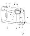
本実施形態は、一般に電子カメラ、デジタルカメラ等と称される形態の撮像装置に本発明を適用したものである。図1に示す本実施形態の撮像装置1は、被写体像を結像するためのレンズ等からなる撮像光学系部材と、撮像光学系部材の結像面に配設された撮像素子96とを保持する鏡枠ユニット20を内部に具備して構成されている。なお、撮像素子96は、CCDやCMOSセンサ等のイメージセンサである。   In the present embodiment, the present invention is applied to an imaging apparatus generally called an electronic camera, a digital camera, or the like. The image pickup apparatus 1 according to the present embodiment shown in FIG. 1 holds an image pickup optical system member composed of a lens or the like for forming a subject image, and an image pickup element 96 disposed on the image formation surface of the image pickup optical system member. The lens frame unit 20 is provided inside. Note that the image sensor 96 is an image sensor such as a CCD or CMOS sensor.

本実施形態の撮像光学系部材は、一例としてプリズム35bを含んでおり、プリズム35bによって光軸を屈曲させる、いわゆる光路反射型、折り曲げ光学系、又は屈曲光学系等と称される形態を有している。本実施形態の撮像装置1では、撮像装置1の被写体に面する側(前方)から入射する光を、いわゆる直角プリズムであるプリズム35bによって90度屈曲させて、撮像素子96の受光部に入射させる構成を有する。   The imaging optical system member of the present embodiment includes a prism 35b as an example, and has a form called a so-called optical path reflection type, a bending optical system, a bending optical system, or the like in which an optical axis is bent by the prism 35b. ing. In the imaging apparatus 1 of the present embodiment, light incident from the side facing the subject (front) of the imaging apparatus 1 is bent by 90 degrees by a prism 35b which is a so-called right-angle prism and is incident on the light receiving unit of the imaging element 96. It has a configuration.

以下の説明では、撮像光学系部材において、被写体からプリズム35bに入射し、プリズム35bの反射面に至るまでの光軸を第1光軸O1と称し、プリズム35bの反射面から撮像素子96に至る光軸を第2光軸O2と称するものとする。言い換えれば、撮像光学系部材において、第1光軸O1はプリズム35bの反射面よりも物体側の光軸のことを指し、第2光軸O2はプリズム35bの反射面よりも像側の光軸のことを指す。   In the following description, in the imaging optical system member, the optical axis from the subject to the prism 35b and reaching the reflecting surface of the prism 35b is referred to as a first optical axis O1, and the reflecting surface of the prism 35b reaches the imaging device 96. The optical axis is referred to as the second optical axis O2. In other words, in the imaging optical system member, the first optical axis O1 indicates the optical axis on the object side with respect to the reflecting surface of the prism 35b, and the second optical axis O2 indicates the optical axis on the image side with respect to the reflecting surface of the prism 35b. Refers to that.

また、以下の説明では、図1に示すように、撮像装置1をいわゆる正立位置で構えた場合のカメラの左右方向をX方向とし、X方向と直交する上下方向をZ方向とし、X、Z方向に直交する前後方向をY方向とする。なお、撮像装置1の正立位置とは、本実施形態では、撮像装置1によって撮像される矩形の画像の長辺が画像中の水平線と略平行となるように撮像装置1を構えた場合のことを称する。また、Y方向について撮像装置1の被写体側を前方とし、撮影者側を後方(背面方向)とする。X方向、Y方向及びZ方向は、一般的には、撮像装置1の幅方向、厚さ方向、高さ方向とも称される。   In the following description, as shown in FIG. 1, when the imaging apparatus 1 is held in a so-called upright position, the left-right direction of the camera is the X direction, the up-down direction orthogonal to the X direction is the Z direction, The front-rear direction perpendicular to the Z direction is taken as the Y direction. In the present embodiment, the erect position of the image pickup apparatus 1 refers to a case where the image pickup apparatus 1 is held so that the long side of the rectangular image picked up by the image pickup apparatus 1 is substantially parallel to the horizontal line in the image. I will call it. Further, in the Y direction, the subject side of the imaging apparatus 1 is the front, and the photographer side is the rear (back direction). The X direction, the Y direction, and the Z direction are generally also referred to as a width direction, a thickness direction, and a height direction of the imaging apparatus 1.

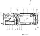
具体的に本実施形態の撮像装置1は、図1、図2及び図3に示すように、箱形状の筐体として互いに対向した状態で結合される筐体部2及び後カバー3と、筐体部2及び後カバー3の内部に収容される鏡枠ユニット20と、カメラ制御基板18とを有して構成されている。   Specifically, as shown in FIGS. 1, 2, and 3, the imaging apparatus 1 of the present embodiment includes a housing unit 2 and a rear cover 3 that are coupled in a state of facing each other as a box-shaped housing, and a housing. The lens frame unit 20 accommodated in the body 2 and the rear cover 3 and the camera control board 18 are configured.

筐体部2には前面部に撮影開口窓部2d、閃光発光装置の発光用窓2e等が配され、上面部に電源スイッチ15およびレリーズスイッチ14が配されている。後カバー3には背面部に撮影モード設定等の操作スイッチ群13と、画像表示装置16が配されている。   The casing 2 is provided with a photographing aperture window 2d on the front surface, a light emission window 2e of a flash light emitting device, and the like, and a power switch 15 and a release switch 14 on the upper surface. The rear cover 3 is provided with an operation switch group 13 for setting a photographing mode and an image display device 16 on the rear surface.

カメラ制御基板18は、カメラの全制御を司るCPU、撮影モード制御部、ストロボ発光制御部、撮像素子による撮影画像データの処理を行う画像処理部、画像記録媒体であるフラッシュメモリに撮影画像データを書き込む記録制御部、ブレ検出センサ等が実装されたプリント回路基板からなり、筐体部2の内部右側に組み込まれる。   The camera control board 18 is a CPU that controls the entire camera, a shooting mode control unit, a strobe light emission control unit, an image processing unit that processes captured image data by the image sensor, and captured image data in a flash memory that is an image recording medium. It consists of a printed circuit board on which a recording control unit for writing, a blur detection sensor, and the like are mounted, and is incorporated in the right side inside the housing unit 2.

図4及び図5に示すように、鏡枠ユニット20は、扁平な外形形状をもつ鏡枠としての鏡枠本体部4と、該鏡枠本体部4内に組み込まれる光学系部材と、鏡枠本体部4のZ方向の下部に配され撮像素子96を保持する撮像素子移動機構部71とを有して構成されている。   As shown in FIGS. 4 and 5, the lens frame unit 20 includes a lens frame main body 4 as a lens frame having a flat outer shape, an optical system member incorporated in the lens frame main body 4, and a lens frame. An image sensor moving mechanism 71 that holds the image sensor 96 is disposed below the main body 4 in the Z direction.

鏡枠本体部4は、鏡枠ユニット20を構成する複数の部材を保持するように構成された、鏡枠ユニット20の骨格となるフレーム部材である。なお、鏡枠本体部4は、単一の部材からなる形態であってもよいし、複数の部材が嵌め合わせ、ネジ締結または接着等によって機械的に結合されて構成される形態であってもよい。   The lens frame main body 4 is a frame member that serves as a skeleton of the lens frame unit 20 and is configured to hold a plurality of members constituting the lens frame unit 20. The lens frame main body 4 may be formed of a single member, or may be formed of a plurality of members fitted and mechanically coupled by screw fastening or adhesion. Good.

鏡枠本体部4の前面には、図5に示すように、所定の厚さを有する略平板状の緩衝部材24が接着剤により固定されている。緩衝部材24は、ゴム等の弾性又は粘弾性を有する材料からなり、一方の主面が、鏡枠ユニット20の鏡枠本体部4の前面部上に接着剤により固定されている。   As shown in FIG. 5, a substantially flat cushioning member 24 having a predetermined thickness is fixed to the front surface of the lens barrel main body 4 with an adhesive. The buffer member 24 is made of a material having elasticity or viscoelasticity such as rubber, and one main surface is fixed on the front surface portion of the lens frame main body 4 of the lens frame unit 20 by an adhesive.

緩衝部材24の前面には、金属又は合成樹脂からなる薄板状の平板部材23が接着剤により固定されている。平板部材23には、後述する筐体部2の凸部2nが内側に嵌合する切り欠き部23aが形成されている。   A thin plate member 23 made of metal or synthetic resin is fixed to the front surface of the buffer member 24 with an adhesive. The flat plate member 23 is formed with a notch portion 23a into which a convex portion 2n of the housing portion 2 described later is fitted.

ここで、撮像装置1内において、鏡枠ユニット20を筐体部2に対して位置決めして保持する構成について説明する。図7に示すように、筐体部2の内面であり、鏡枠ユニット20の前面と対向する面上には、平板部材23の切り欠き部23aに対応した位置に凸部2nが形成されている。凸部2nは、前述したように、平板部材23の切り欠き部23a内に嵌合する形状を有している。   Here, a configuration in which the lens barrel unit 20 is positioned and held with respect to the housing unit 2 in the imaging apparatus 1 will be described. As shown in FIG. 7, a convex portion 2 n is formed on the inner surface of the housing portion 2 on the surface facing the front surface of the lens frame unit 20 at a position corresponding to the notch portion 23 a of the flat plate member 23. Yes. As described above, the protrusion 2n has a shape that fits into the notch 23a of the flat plate member 23.

鏡枠ユニット20は、筐体部2にネジ29によって固定される押さえ板27、28、29によって、筐体部2の凸部2nが設けられた面に向かって付勢される。鏡枠ユニット20は、平板部材23の切り欠き部23aが、筐体部2の凸部2nと嵌合することによって、平板部材23及び緩衝部材24を介して筐体部2に対して所定の位置に保持される。   The lens frame unit 20 is urged toward the surface on which the convex portion 2n of the housing part 2 is provided by pressing plates 27, 28, and 29 fixed to the housing part 2 by screws 29. The lens frame unit 20 has a predetermined portion with respect to the housing part 2 via the flat plate member 23 and the buffer member 24 by fitting the notch part 23a of the flat plate member 23 with the convex part 2n of the housing part 2. Held in position.

緩衝部材24は、弾性又は粘弾性を有する材料からなることから、撮像装置1の落下等によって筐体部2または後カバー3に衝撃力が与えられた場合において、鏡枠ユニット20に加わる衝撃力を緩和する効果を発揮する。ここで、緩衝部材24は、略平板状であり、図8に示すように筐体部2と鏡枠ユニット20との間に介装されていることから、緩衝部材24が生ずる緩衝効果は、緩衝部材24の主面に沿う方向の衝撃力が加わり緩衝部材24がせん断変形する場合に高くなる。すなわち、撮像装置1に、光軸O1に略直交する方向(X方向及びZ方向)の衝撃力が加えられる場合に、緩衝部材24がせん断変形し、緩衝部材24による緩衝効果が最も高くなる。   Since the buffer member 24 is made of a material having elasticity or viscoelasticity, an impact force applied to the lens frame unit 20 when an impact force is applied to the casing unit 2 or the rear cover 3 due to a drop of the imaging device 1 or the like. Demonstrate the effect of relaxing. Here, since the buffer member 24 has a substantially flat plate shape and is interposed between the housing 2 and the lens frame unit 20 as shown in FIG. 8, the buffer effect produced by the buffer member 24 is as follows. It becomes high when the impact force in the direction along the main surface of the buffer member 24 is applied and the buffer member 24 undergoes shear deformation. That is, when an impact force in a direction (X direction and Z direction) substantially orthogonal to the optical axis O1 is applied to the imaging device 1, the buffer member 24 is sheared and the buffer effect by the buffer member 24 becomes the highest.

以上に説明したように、本実施形態の撮像装置1は、筐体部2に対して緩衝部材24を介して鏡枠ユニット20を弾性的に保持する構成を有しており、緩衝部材24が鏡枠ユニット20に対して緩衝効果を発揮するようにせん断変形する方向は、X方向及びZ方向である。すなわち、撮像装置1に光軸O2に沿う方向の衝撃力が加えられた場合には、緩衝部材24がせん断変形し、鏡枠ユニット20は、筐体部2に対して光軸O2に沿う方向に相対的に移動する。   As described above, the imaging apparatus 1 according to the present embodiment has a configuration in which the lens frame unit 20 is elastically held via the buffer member 24 with respect to the housing unit 2. The directions of shear deformation so as to exert a buffering effect on the lens frame unit 20 are the X direction and the Z direction. That is, when an impact force in the direction along the optical axis O <b> 2 is applied to the imaging device 1, the buffer member 24 is sheared and the lens frame unit 20 is in a direction along the optical axis O <b> 2 with respect to the housing unit 2. Move relative to.

鏡枠本体部4の下部には、図5及び図6に示すように、下方に向かって突出する一対の突起部4a、4bが設けられている。突起部4a、4bは、図6のように鏡枠ユニット20を光軸O2に沿って下方から見た場合に露出する位置に配設されている。突起部4a、4bは、緩衝部材24が変形することによって鏡枠ユニット20が筐体部2に対して相対的に下方に変位した場合に、鏡枠ユニット20を構成する部材の中で最初に筐体部2に直接接する部位である。   As shown in FIGS. 5 and 6, a pair of projecting portions 4 a and 4 b projecting downward are provided at the lower portion of the lens frame main body portion 4. The protrusions 4a and 4b are disposed at positions that are exposed when the lens barrel unit 20 is viewed from below along the optical axis O2 as shown in FIG. The protrusions 4a and 4b are the first of the members constituting the lens frame unit 20 when the lens frame unit 20 is displaced downward relative to the housing 2 due to the deformation of the buffer member 24. This is a part that directly contacts the housing part 2.

言い換えれば、鏡枠ユニット20が筐体部2に対して光軸O2に沿って像側に向かって移動した場合に、突起部4a、4bは、鏡枠ユニット20を構成する部材の中で最初に筐体部2に直接接する。すなわち、突起部4a、4bは、鏡枠ユニット20が光軸O2に沿って像側に向かって移動する範囲を規制するストッパーとして機能する。なお、突起部は本実施形態のような2箇所に限らず3箇所以上に設けられる形態であってもよいし、1箇所のみに設けられる形態であってもよい。   In other words, when the lens frame unit 20 moves toward the image side along the optical axis O <b> 2 with respect to the housing unit 2, the protrusions 4 a and 4 b are first among members constituting the lens frame unit 20. Directly in contact with the housing 2. That is, the protrusions 4a and 4b function as stoppers that restrict the range in which the lens barrel unit 20 moves toward the image side along the optical axis O2. In addition, the form provided in three or more places may be sufficient as a projection part not only in two places like this embodiment, The form provided in only one place may be sufficient.

より具体的に本実施形態では、図6に示すように鏡枠ユニット20を光軸O2に沿って下方から見た場合に、一対の突起部4a、4bは、光軸O2をX方向に挟むように配設されている。一方の突起部4aは、光軸O2よりも左側に配設されており、他方の突起部4bは、光軸O2よりも右方に配設されている。言い換えれば、一対の突起部4a、4bは、鏡枠ユニット20を光軸O2に沿って下方から見た場合に、両者間に撮像素子96が位置するように配設されている。   More specifically, in the present embodiment, when the lens barrel unit 20 is viewed from below along the optical axis O2, as shown in FIG. 6, the pair of protrusions 4a and 4b sandwich the optical axis O2 in the X direction. It is arranged like this. One projection 4a is disposed on the left side of the optical axis O2, and the other projection 4b is disposed on the right side of the optical axis O2. In other words, the pair of protrusions 4a and 4b are arranged so that the imaging element 96 is positioned between the pair of protrusions 4a and 4b when the lens barrel unit 20 is viewed from below along the optical axis O2.

鏡枠本体部4内に組み込まれる光学系部材は、図4及びに示すように、プリズム35bを含み鏡枠本体部4に対して位置が固定された第1レンズ群と、光軸O2に沿ってそれぞれが独立して移動可能に配設された第2レンズ群36、第3レンズ群38及び第4レンズ群39とによって構成されている。第2レンズ群36、第3レンズ群38及び第4レンズ群39をそれぞれ光軸O2に沿って移動させる機構については、公知の技術であるためその説明を省略するものとする。なお、図示しないが、光学系部材には、シャッター機構、可変絞り機構、NDフィルタ等が含まれていてもよい。   As shown in FIG. 4 and FIG. 4, the optical system member incorporated in the lens frame main body 4 includes the first lens group including the prism 35 b and the position is fixed with respect to the lens frame main body 4, and along the optical axis O <b> 2. The second lens group 36, the third lens group 38, and the fourth lens group 39 are movably disposed independently of each other. Since the mechanism for moving the second lens group 36, the third lens group 38, and the fourth lens group 39 along the optical axis O2 is a known technique, the description thereof will be omitted. Although not shown, the optical system member may include a shutter mechanism, a variable aperture mechanism, an ND filter, and the like.

次に、撮像素子移動機構部71の構成について説明する。撮像素子移動機構部71は、撮像素子96を、光軸O2に対して相対的に移動可能に保持するように構成されている。撮像素子移動機構部71は、カメラ制御基板18に設けられたブレ検出センサによって検出された撮像装置1の移動(ブレ)量に基づいて撮像素子96を移動させることによって、撮像される画像のブレを防止または抑制する機能を実現するための構成である。この撮像される画像のブレを防止または抑制する機能は、一般に、例えばブレ補正機能等と称される。また、撮像素子96を移動させる形態のブレ補正機能は、一般に、イメージセンサシフト方式等と称される。   Next, the configuration of the image sensor moving mechanism unit 71 will be described. The image sensor moving mechanism 71 is configured to hold the image sensor 96 so as to be movable relative to the optical axis O2. The image sensor moving mechanism 71 moves the image sensor 96 based on the movement (blur) amount of the image pickup apparatus 1 detected by the camera shake detection sensor provided on the camera control board 18, thereby blurring the image to be captured. This is a configuration for realizing a function of preventing or suppressing the above. This function of preventing or suppressing blurring of a captured image is generally called, for example, a blur correction function. Further, the blur correction function in the form of moving the image sensor 96 is generally referred to as an image sensor shift method.

本実施形態の撮像素子移動機構部71は、撮像素子96を、光軸O2に略直交する平面に沿って撮像素子96を移動可能に保持している。より具体的には、撮像素子移動機構部71は、鏡枠本体部4に対してX方向に移動可能な第1移動部材であるXスライダ89と、Xスライダ89に対してY方向に移動可能な第2移動部材であり撮像素子96が固定された撮像素子保持部91と、Xスライダ89及び撮像素子保持部91をそれぞれX方向及びY方向に移動させる駆動機構部を有して構成されている。   The image sensor moving mechanism 71 of the present embodiment holds the image sensor 96 so that the image sensor 96 can move along a plane substantially orthogonal to the optical axis O2. More specifically, the image sensor moving mechanism 71 is movable in the Y direction with respect to the X slider 89 that is a first moving member that can move in the X direction with respect to the lens barrel body 4 and the X slider 89. An image sensor holding unit 91 that is a second moving member and to which the image sensor 96 is fixed, and a drive mechanism unit that moves the X slider 89 and the image sensor holding unit 91 in the X direction and the Y direction, respectively. Yes.

撮像素子保持部91は、詳しくは後述するが、光軸O2が通過する中央開口部91aを有する枠状の部材である。撮像素子保持部91の下方側には撮像素子96が固定され、撮像素子96は、中央開口部91aを介して撮像素子保持部91の上方に向かって露出する。   As will be described in detail later, the image sensor holding unit 91 is a frame-like member having a central opening 91a through which the optical axis O2 passes. An image pickup device 96 is fixed to the lower side of the image pickup device holding portion 91, and the image pickup device 96 is exposed to the upper side of the image pickup device holding portion 91 through the central opening 91a.

図9に示すように、Xスライダ89は、鏡枠本体部4に固定された第1ガイド部である丸軸状のXガイド軸86によって鏡枠本体部4に連結され、Xガイド軸86によってX方向に移動するように案内される。また、図10に示すように、撮像素子保持部91は、Xスライダ89に固定された第2ガイド部である丸軸状のYガイド軸92によってXスライダ89に連結され、Yガイド軸92によってY方向に移動するように案内される。   As shown in FIG. 9, the X slider 89 is connected to the lens frame main body 4 by a round shaft-shaped X guide shaft 86 which is a first guide portion fixed to the lens frame main body 4, and the X guide shaft 86 Guided to move in the X direction. As shown in FIG. 10, the image sensor holding portion 91 is connected to the X slider 89 by a round shaft-shaped Y guide shaft 92 that is a second guide portion fixed to the X slider 89. Guided to move in the Y direction.

より詳細に説明すると、図10に示すように、Xスライダ89にはX方向に同一軸上に配設された貫通孔である一対の軸受部89a及び89bと、Y方向に同一軸上に配設された貫通孔である一対の軸保持穴89c及び89dとが穿設されている。   More specifically, as shown in FIG. 10, the X slider 89 has a pair of bearing portions 89a and 89b which are through holes disposed on the same axis in the X direction, and the same axis in the Y direction. A pair of shaft holding holes 89c and 89d which are provided through holes are formed.

Xスライダ89に設けられた一対の軸受部89a及び89bは、鏡枠本体部4に固定されたXガイド軸86が挿入される穴であり、Xスライダ89は、この一対の軸受部89a及び89bにおいて、Xガイド軸86に沿って摺動する。また、Xスライダ89に設けられた一対の軸保持穴89c及び89dは、内部に嵌入されたYガイド軸92をXスライダ89に対して固定するための穴である。また、Xスライダ89には、軸受部89aの側方位置に、U字状切り欠き部89fが設けられている。   A pair of bearing portions 89a and 89b provided on the X slider 89 are holes into which an X guide shaft 86 fixed to the lens barrel main body 4 is inserted, and the X slider 89 includes the pair of bearing portions 89a and 89b. , Slide along the X guide shaft 86. A pair of shaft holding holes 89 c and 89 d provided in the X slider 89 are holes for fixing the Y guide shaft 92 fitted inside the X slider 89 to the X slider 89. Further, the X slider 89 is provided with a U-shaped notch 89f at a side position of the bearing 89a.

撮像素子保持部91の右側の端部には、Y方向に同一軸上に配設された貫通孔である一対の軸受部91d及び91eが穿設されている。撮像素子保持部91に設けられた一対の軸受部91d及び91eは、Xスライダ89に固定されたYガイド軸92が挿入される穴であり、撮像素子保持部91は、この一対の軸受部91d及び91eにおいて、Yガイド軸92に沿って摺動する。   A pair of bearing portions 91d and 91e, which are through-holes disposed on the same axis in the Y direction, are formed in the right end portion of the image sensor holding portion 91. A pair of bearing portions 91d and 91e provided in the image sensor holding portion 91 are holes into which a Y guide shaft 92 fixed to the X slider 89 is inserted, and the image sensor holding portion 91 is a pair of bearing portions 91d. And 91e slide along the Y guide shaft 92.

また、撮像素子保持部91には、軸受部91eの上方位置に、U字状切り欠き部91fが設けられている。また撮像素子保持部91の左側の端部には、ガイド用突起91cが設けられている。   Further, the image sensor holding portion 91 is provided with a U-shaped cutout portion 91f at a position above the bearing portion 91e. A guide protrusion 91 c is provided at the left end of the image sensor holding portion 91.

撮像素子保持部91とXスライダ89とを連結する場合、まず、Yガイド軸92をXスライダ89の軸保持穴89cから挿入し、その後Yガイド軸92を順に軸受部91d、軸保持穴89d、軸受部91eに貫通させる。そして、Yガイド軸92とXスライダ89とを接着剤により固定する。なおこの状態において、Yガイド軸92は、Xスライダ89に固定された状態において、Yガイド軸92の前方側の先端部が、撮像素子保持部91の前端面よりも前方外部に突出する。   When connecting the image sensor holding portion 91 and the X slider 89, first, the Y guide shaft 92 is inserted from the shaft holding hole 89c of the X slider 89, and then the Y guide shaft 92 is sequentially inserted into the bearing portion 91d, the shaft holding hole 89d, The bearing 91e is penetrated. Then, the Y guide shaft 92 and the X slider 89 are fixed with an adhesive. In this state, when the Y guide shaft 92 is fixed to the X slider 89, the front end portion of the Y guide shaft 92 protrudes forward and outward from the front end surface of the image sensor holding portion 91.

また、撮像素子保持部91とXスライダ89との間には、図示しない引張バネが懸架される。該引張バネは、撮像素子保持部91を、Xスライダ89に対してY方向後方に向かって付勢する力を発生するように配設されている。以上のように、撮像素子保持部91は、Xスライダ89に対して、引張バネによってY方向後方に向かって付勢された状態で、Y方向に相対移動可能に支持されている。   Further, a tension spring (not shown) is suspended between the image sensor holding portion 91 and the X slider 89. The tension spring is disposed so as to generate a force that urges the image sensor holding portion 91 toward the rear in the Y direction with respect to the X slider 89. As described above, the image sensor holding portion 91 is supported so as to be relatively movable in the Y direction while being urged rearward in the Y direction by the tension spring with respect to the X slider 89.

図9及び図11に示すように、鏡枠本体部4の下部であって光軸O2よりも右側には、X方向に同一軸上に配設された貫通孔である一対の軸保持穴4f及び4gが設けられている。鏡枠本体部4に設けられた一対の軸保持穴は、内部に嵌入されたXガイド軸86を鏡枠本体部4に対して固定するための穴である。   As shown in FIGS. 9 and 11, a pair of shaft holding holes 4f, which are through-holes arranged on the same axis in the X direction, on the lower side of the lens frame body 4 and on the right side of the optical axis O2. And 4 g are provided. The pair of shaft holding holes provided in the lens frame main body 4 are holes for fixing the X guide shaft 86 fitted therein to the lens frame main body 4.

鏡枠本体部4とXスライダ89とを連結する場合、Xガイド軸86をXスライダ89の軸受部89aから挿入し、その後Xガイド軸86を順に軸保持穴4f、軸受部89b、軸保持穴4gに挿入する。また、このとき、Xガイド軸86の周囲であって軸受部89bと軸保持穴4fとの間には、圧縮コイルバネ87が配設される(図9)。そして、Xガイド軸86と鏡枠本体部4とを接着剤により固定する。これにより、Xスライダ89は、圧縮コイルバネ87により鏡枠本体部4に対してX方向左方に向かって付勢された状態で、鏡枠本体部4に対してX方向に相対移動可能に支持される。   When connecting the lens frame main body 4 and the X slider 89, the X guide shaft 86 is inserted from the bearing portion 89a of the X slider 89, and then the X guide shaft 86 is inserted into the shaft holding hole 4f, the bearing portion 89b, and the shaft holding hole. Insert into 4g. At this time, a compression coil spring 87 is disposed around the X guide shaft 86 and between the bearing portion 89b and the shaft holding hole 4f (FIG. 9). Then, the X guide shaft 86 and the lens frame body 4 are fixed with an adhesive. As a result, the X slider 89 is supported by the compression coil spring 87 so as to be movable relative to the lens frame body 4 in the X direction while being urged to the left in the X direction with respect to the lens frame body 4. Is done.

また、図11に示すように、軸保持穴4f及び4gの下方位置からY方向前方側に離間した位置の鏡枠本体部4の壁面部には、長手方向がX方向に沿う長穴形状の軸受部4kが設けられている。軸受部4kは、撮像素子保持部91の前端面から前方に向かって突出するYガイド軸92の前方側の先端部が挿入される位置に設けられている。   Further, as shown in FIG. 11, the wall surface of the lens barrel body 4 at a position spaced forward from the lower position of the shaft holding holes 4f and 4g in the Y direction has a long hole shape with the longitudinal direction extending along the X direction. A bearing portion 4k is provided. The bearing portion 4k is provided at a position where the front end portion of the Y guide shaft 92 protruding forward from the front end surface of the image sensor holding portion 91 is inserted.

軸受部4kの幅は、Yガイド軸92の前方側の先端部が内部においてガタなくX方向に摺動可能な値とされている。Yガイド軸92の前方側の先端部が、軸受部4kによって支持されることによって、Xガイド軸86によってX方向に案内されるXスライダ89及び撮像素子保持部91の、Xガイド軸86周りの回動が規制される。   The width of the bearing portion 4k is set such that the front end portion of the Y guide shaft 92 is slidable in the X direction without any play. The front end portion of the Y guide shaft 92 is supported by the bearing portion 4k, so that the X slider 89 and the image sensor holding portion 91 guided in the X direction by the X guide shaft 86 around the X guide shaft 86. The rotation is restricted.

また、鏡枠本体部4の下部であって光軸O2よりも左側には、第3のガイド部である軸受部4rと、フォトインタラプタ69x及び69yが設けられている。フォトインタラプタ69x及び69yは、後述する駆動機構部を構成する電動モータの原点検出用に用いられるものである。   Further, a bearing portion 4r which is a third guide portion and photo interrupters 69x and 69y are provided below the lens frame main body portion 4 and on the left side of the optical axis O2. The photo interrupters 69x and 69y are used for detecting the origin of an electric motor that constitutes a drive mechanism section described later.

軸受部4rは、撮像素子保持部91から左方に突出するガイド用突起91cにZ方向(上下方向)両方向から接する形状を有している。また、軸受部4rとガイド用突起91cとは、X方向及びY方向に相対的に摺動可能である。すなわち、ガイド用突起91cは、軸受部4r内において、Z方向へのガタが無い状態で、X方向及びY方向に摺動可能である。言い換えれば、軸受部4rは、ガイド用突起91cをZ方向(光軸O2に沿う方向)に挟持することによって、ガイド用突起91cのZ方向への移動を規制し、かつガイド用突起91cのX方向及びY方向の移動を妨げないように、ガイド用突起91cを支持するように構成されている。   The bearing portion 4r has a shape that comes into contact with a guide protrusion 91c protruding leftward from the image sensor holding portion 91 from both directions in the Z direction (vertical direction). Further, the bearing portion 4r and the guide projection 91c are relatively slidable in the X direction and the Y direction. That is, the guide protrusion 91c can slide in the X direction and the Y direction in the bearing portion 4r without any play in the Z direction. In other words, the bearing portion 4r regulates the movement of the guide protrusion 91c in the Z direction by sandwiching the guide protrusion 91c in the Z direction (the direction along the optical axis O2), and the guide protrusion 91c X The guide projection 91c is supported so as not to hinder movement in the direction and the Y direction.

撮像素子保持部91の光軸O2よりも左側にあるガイド用突起91cが、軸受部4rによって支持されることによって、Yガイド軸92によってY方向に案内される撮像素子保持部91の、Yガイド軸92周りの回動が規制される。   The guide protrusion 91c on the left side of the optical axis O2 of the image pickup device holding portion 91 is supported by the bearing portion 4r, whereby the Y guide of the image pickup device holding portion 91 guided in the Y direction by the Y guide shaft 92. The rotation around the shaft 92 is restricted.

また、撮像素子保持部91と鏡枠本体部4との間には、図示しない引張バネが懸架される。この引張バネの付勢力によって、Yガイド軸92に対する撮像素子保持部91のガタが除かれる。   Further, a tension spring (not shown) is suspended between the image sensor holding portion 91 and the lens barrel main body portion 4. The backlash of the image sensor holding portion 91 with respect to the Y guide shaft 92 is removed by the urging force of the tension spring.

以上に説明したように、Xスライダ89は、鏡枠本体部4に対してXガイド軸86によりX方向にガイドされ、圧縮コイルバネ87により左方向の付勢力を受けた状態で支持されている。Xスライダ89は、U字状切り欠き部89fを後述するナット76で押圧することにより鏡枠本体部4に対してX方向に変位可能である。一方、撮像素子保持部91は、X方向にはXスライダ89とともに変位可能な状態であり、かつY方向にYガイド軸92によってガイドされ、引張バネによる後方への付勢力を受けた状態で支持されている。撮像素子保持部91は、U字状切り欠き部91fを後述するナットで押圧することにより鏡枠本体部4に対してY方向にも変位可能である。すなわち、撮像素子保持部91は、鏡枠本体部4に対して光軸O2に直交するXY平面上を二次元的に変位可能である。   As described above, the X slider 89 is guided in the X direction by the X guide shaft 86 with respect to the lens barrel main body 4, and is supported in a state in which it receives the urging force in the left direction by the compression coil spring 87. The X slider 89 can be displaced in the X direction with respect to the lens barrel main body 4 by pressing the U-shaped notch 89 f with a nut 76 described later. On the other hand, the image sensor holding portion 91 is displaceable together with the X slider 89 in the X direction, is guided by the Y guide shaft 92 in the Y direction, and is supported in a state of receiving a rearward biasing force by a tension spring. Has been. The image sensor holding portion 91 can be displaced in the Y direction with respect to the lens barrel main body portion 4 by pressing the U-shaped cutout portion 91f with a nut described later. That is, the image sensor holding portion 91 can be displaced two-dimensionally on the XY plane orthogonal to the optical axis O2 with respect to the lens barrel main body portion 4.

以上のように、鏡枠本体部4に対してX方向及びY方向に変位可能に支持されたXスライダ89及び撮像素子保持部91は、駆動機構部によってX方向及びY方向に駆動されるの構成について説明する。駆動機構部は、Xスライダ89をX方向に駆動するX駆動機構部と、撮像素子保持部91をY方向に駆動するY駆動機構部とからなる。   As described above, the X slider 89 and the image sensor holding unit 91 supported so as to be displaceable in the X direction and the Y direction with respect to the lens barrel body 4 are driven in the X direction and the Y direction by the drive mechanism unit. The configuration will be described. The drive mechanism unit includes an X drive mechanism unit that drives the X slider 89 in the X direction, and a Y drive mechanism unit that drives the image sensor holding unit 91 in the Y direction.

X駆動機構部は、図9及び図11に示すように、ステッピングモータからなる電動モータ72と、ギヤ73及び74を介して電動モータ72によって回転駆動されるスクリュー75と、スクリュー75に螺合するナット76とを有して構成されている。   As shown in FIGS. 9 and 11, the X drive mechanism section is screwed into the electric motor 72 formed of a stepping motor, a screw 75 that is rotationally driven by the electric motor 72 via gears 73 and 74, and the screw 75. And a nut 76.

スクリュー75は、Xスライダ89に設けられたU字状切り欠き89f内を通り、回転軸がX方向に沿うように配設されている。ナット76は、スクリュー75周りの回動が規制されており、電動モータ72によって回転駆動されるスクリュー75の回動に伴ってX方向に移動する。   The screw 75 passes through a U-shaped notch 89f provided in the X slider 89, and is arranged so that the rotation axis is along the X direction. The rotation of the nut 76 around the screw 75 is restricted, and the nut 76 moves in the X direction as the screw 75 driven to rotate by the electric motor 72 rotates.

また、Xスライダ89は、Xガイド軸86周りに配設された圧縮コイルバネ87によって、ナット76に向かって付勢される。このため、Xスライダ89は、U字状切り欠き部89f近傍が常にナット76に接し、Xスライダ89は、電動モータ72の回転に応じてX方向に進退移動するナット76に従ってX方向に変位する。   The X slider 89 is biased toward the nut 76 by a compression coil spring 87 disposed around the X guide shaft 86. For this reason, the X slider 89 is always in contact with the nut 76 in the vicinity of the U-shaped notch 89f, and the X slider 89 is displaced in the X direction according to the nut 76 that moves forward and backward in the X direction according to the rotation of the electric motor 72. .

Y駆動機構部の構成は、配設される向きが異なるが、前記X駆動機構部と同様である。図12に示すように、Y駆動機構部は、ステッピングモータからなる電動モータ79と、ギヤ81及び82を介して電動モータ79によって回転駆動されるスクリュー83と、スクリュー83に螺合するナット84とを有して構成されている。   The configuration of the Y drive mechanism section is the same as that of the X drive mechanism section, although the arrangement direction is different. As shown in FIG. 12, the Y drive mechanism section includes an electric motor 79 formed of a stepping motor, a screw 83 that is rotationally driven by the electric motor 79 via gears 81 and 82, and a nut 84 that is screwed into the screw 83. It is comprised.

スクリュー83は、撮像素子保持部91に設けられたU字状切り欠き部91f内を通り、回転軸がY方向に沿うように配設されている。ナット84は、スクリュー83周りの回動が規制されており、電動モータ79によって回転駆動されるスクリュー83の回動に伴ってY方向に移動する。   The screw 83 passes through a U-shaped notch 91f provided in the image sensor holding portion 91, and is arranged so that the rotation axis is along the Y direction. The rotation of the nut 84 around the screw 83 is restricted, and the nut 84 moves in the Y direction as the screw 83 rotated by the electric motor 79 rotates.

また、撮像素子保持部91は、図示しない引張バネによってナット84に向かって付勢される。このため、撮像素子保持部91は、U字状切り欠き91f近傍が常にナット84に接し、撮像素子保持部91は、電動モータ79の回転に応じてY方向に進退移動するナット84に従ってY方向に変位する。   Further, the image sensor holding portion 91 is biased toward the nut 84 by a tension spring (not shown). For this reason, the imaging element holding part 91 is always in contact with the nut 84 in the vicinity of the U-shaped notch 91f, and the imaging element holding part 91 follows the nut 84 that moves forward and backward in the Y direction according to the rotation of the electric motor 79. It is displaced to.

以上に説明したように、撮像素子96が固定された撮像素子保持部91は、駆動機構部によって、鏡枠本体部4に対して光軸O2に直交するX方向及びY方向に変位駆動される。   As described above, the image sensor holding unit 91 to which the image sensor 96 is fixed is displaced and driven by the drive mechanism unit in the X and Y directions perpendicular to the optical axis O2 with respect to the lens barrel main body 4. .

次に、撮像素子保持部91に撮像素子96を固定する構成について説明する。   Next, a configuration for fixing the image sensor 96 to the image sensor holding unit 91 will be described.

図13及び図15に示すように、撮像素子96は、プリント回路基板95上に実装されている。なお、本実施形態では、撮像素子としての機能を発揮するベアチップの周囲をケース及びカバーガラスによって封止した、いわゆる撮像素子パッケージのことを撮像素子96と称している。撮像素子96とプリント回路基板95とは、半田付けや異方性導電接着剤等によって固定されている。   As shown in FIGS. 13 and 15, the image sensor 96 is mounted on a printed circuit board 95. In the present embodiment, a so-called image pickup device package in which the periphery of a bare chip that functions as an image pickup device is sealed with a case and a cover glass is referred to as an image pickup device 96. The image sensor 96 and the printed circuit board 95 are fixed by soldering, anisotropic conductive adhesive, or the like.

本実施形態の撮像素子96は、光軸O2に沿って見た場合に、略矩形状の板状の形状を有している。以下の説明では、撮像素子96が受光する側の面を受光面と称し、受光面とは反対側の面を裏面と称するものとする。また、撮像素子96を光軸O2に沿って見た場合に外周となる面を側面と称する。   The image sensor 96 of the present embodiment has a substantially rectangular plate shape when viewed along the optical axis O2. In the following description, the surface on the side where the image sensor 96 receives light is referred to as a light receiving surface, and the surface opposite to the light receiving surface is referred to as a back surface. In addition, when the imaging device 96 is viewed along the optical axis O2, a surface that is an outer periphery is referred to as a side surface.

プリント回路基板95は、本実施形態では一例として、図示するように両面実装形式の硬質な基板であり、撮像素子96が実装された面とは反対側の裏面上に、電子部品95aやコネクタ95bが実装されている。コネクタ95bは、図示しないフレキシブルプリント回路基板(FPC)を接続可能に構成されている。   As an example in this embodiment, the printed circuit board 95 is a hard board of a double-sided mounting type as illustrated, and an electronic component 95a and a connector 95b are provided on the back surface opposite to the surface on which the image sensor 96 is mounted. Has been implemented. The connector 95b is configured to be able to connect a flexible printed circuit board (FPC) (not shown).

撮像素子96及びプリント回路基板95は、コネクタ95bに接続されるフレキシブルプリント回路基板を介して、カメラ制御基板18に電気的に接続される。なお、プリント回路基板95は、裏面上に電子部品等が実装されない片面実装形式であってもよい、またプリント回路基板95は、柔軟なフレキシブルプリント回路基板であってもよい。   The image sensor 96 and the printed circuit board 95 are electrically connected to the camera control board 18 through a flexible printed circuit board connected to the connector 95b. The printed circuit board 95 may be a single-sided mounting type in which electronic components or the like are not mounted on the back surface, and the printed circuit board 95 may be a flexible flexible printed circuit board.

撮像素子96は、枠部材97に接着剤100によって固定されている。枠部材97は、詳しくは後述するが、ネジ102によって撮像素子保持部91に締結される部材である。すなわち、撮像素子96は、枠部材97を介して、撮像素子保持部91に固定される。   The image sensor 96 is fixed to the frame member 97 with an adhesive 100. Although described in detail later, the frame member 97 is a member fastened to the image sensor holding portion 91 by a screw 102. That is, the image sensor 96 is fixed to the image sensor holding unit 91 via the frame member 97.

枠部材97は、光軸O2に沿って見た場合に、中央部において光軸O2方向に貫通する開口部97aと、光軸O2に沿って見た場合に、外周部の複数箇所において撮像素子96の外形よりも外側に突出する複数の鍔状部97bを有している。   When viewed along the optical axis O2, the frame member 97 has an opening 97a penetrating in the direction of the optical axis O2 at the center portion, and when viewed along the optical axis O2, the image pickup element at a plurality of locations on the outer peripheral portion. A plurality of hook-shaped portions 97b projecting outward from the outer shape of 96.

本実施形態の枠部材97は、板状の部材を、XZ平面による断面がハット状となるように折り曲げた形状を有している。すわなち、枠部材97は、板状部材を、Y方向から見た場合にコ字形状となるように折り曲げた部分であるチャンネル状部と、該チャンネル状部の一対の側面の端部をそれぞれX方向外側に向かって折り曲げた部分である鍔状部97bとを有する。   The frame member 97 of the present embodiment has a shape obtained by bending a plate-like member so that a cross section taken along the XZ plane is a hat shape. In other words, the frame member 97 includes a channel-like portion that is a portion obtained by bending the plate-like member into a U shape when viewed from the Y direction, and ends of a pair of side surfaces of the channel-like portion. Each has a hook-like portion 97b that is a portion bent outward in the X direction.

撮像素子96は、接着剤100によって枠部材97に対して固定されている。撮像素子96及びプリント回路基板95は、枠部材97に直接的に接触しておらず、枠部材97から離れた状態において、枠部材97に対して接着剤100を介して固定されている。撮像素子96の有効画素領域96dは、開口部97aを介して光軸O2の物体側(撮像光学系部材側)に向かって露出する。   The image sensor 96 is fixed to the frame member 97 with an adhesive 100. The imaging element 96 and the printed circuit board 95 are not in direct contact with the frame member 97 but are fixed to the frame member 97 via the adhesive 100 in a state of being separated from the frame member 97. The effective pixel region 96d of the image sensor 96 is exposed toward the object side (imaging optical system member side) of the optical axis O2 through the opening 97a.

枠部材97は、撮像素子保持部材91にZ方向下方から上方に向かって螺合する複数のネジ102によって、撮像素子保持部91の下方側に締結される。枠部材97には、図13に示すように、鍔状部97bに穿設された3つの貫通孔97dが設けられている。3つの貫通孔97dは、Z方向(光軸O2方向)から枠部材97を見た場合に、開口部97aの周囲に、3つ全てが同一直線状に並ばないように配設されている。本実施形態では、左方に延出する鍔状部97bに1つの貫通孔97dが穿設されており、右方に延出する鍔状部97bに2つの貫通孔97dが穿設されている。   The frame member 97 is fastened to the lower side of the image sensor holding unit 91 by a plurality of screws 102 that are screwed onto the image sensor holding member 91 from below in the Z direction upward. As shown in FIG. 13, the frame member 97 is provided with three through-holes 97d drilled in the bowl-shaped portion 97b. The three through holes 97d are arranged around the opening 97a so that all three do not line up in the same straight line when the frame member 97 is viewed from the Z direction (optical axis O2 direction). In the present embodiment, one through hole 97d is formed in the hook-shaped portion 97b extending leftward, and two through-holes 97d are formed in the hook-shaped portion 97b extending rightward. .

撮像素子保持部91の下方側の面上には、ネジ102が螺合するネジ穴を有する略平面状の台座部91hが設けられている。台座部91hは、ネジ穴が枠部材97の貫通孔97dに対応する位置に設けられている。すなわち、本実施形態では、撮像素子保持部91の下方側の面上の3箇所に台座部91hが設けられている。台座部91hは、中央開口部91aに対して右側に1箇所、左側に2箇所設けられている。   On the lower surface of the image sensor holding portion 91, a substantially flat pedestal portion 91h having a screw hole into which the screw 102 is screwed is provided. The pedestal portion 91 h is provided at a position where the screw hole corresponds to the through hole 97 d of the frame member 97. That is, in the present embodiment, the pedestal portions 91 h are provided at three locations on the lower surface of the image sensor holding portion 91. The pedestal portion 91h is provided at one place on the right side and two places on the left side with respect to the central opening 91a.

ここで、本実施形態では一例として、台座部91hは、図14に示すようにネジ穴の軸方向から見て略円形状の凸部であり、周囲の面よりも所定の高さHだけ突出するように形成されている。   Here, as an example in the present embodiment, the pedestal portion 91h is a substantially circular convex portion as seen from the axial direction of the screw hole as shown in FIG. 14, and protrudes by a predetermined height H from the surrounding surface. It is formed to do.

枠部材97は、3箇所の貫通孔97dに挿通され、それぞれ台座部97dのネジ穴に光軸O2と略平行に像側から物体側に向かって螺合する3つネジ102によって、撮像素子保持部91に締結され固定される。なお、本実施形態では、枠部材97は、3箇所においてネジ102によって撮像素子保持部91に締結されるが、枠部材97は4箇所においてネジ102によって撮像素子保持部91に締結される形態であってもよい。   The frame member 97 is inserted into the three through holes 97d, and is held by the image pickup element by three screws 102 that are screwed into the screw holes of the pedestal portion 97d from the image side to the object side substantially parallel to the optical axis O2. Fastened and fixed to the portion 91. In the present embodiment, the frame member 97 is fastened to the image sensor holding portion 91 by screws 102 at three locations, but the frame member 97 is fastened to the image sensor holding portion 91 by screws 102 at four locations. There may be.

枠部材97が撮像素子保持部91に締結されることにより、撮像素子96が撮像素子保持部91に固定される。ここで、枠部材97と3箇所の台座部91hとの間には、後述する調整部材103、104が挟み込まれている。また、枠部材97と3つのネジ102の頭部との間には、後述する付勢部材101が挟み込まれている。   By fastening the frame member 97 to the image sensor holding unit 91, the image sensor 96 is fixed to the image sensor holding unit 91. Here, adjustment members 103 and 104, which will be described later, are sandwiched between the frame member 97 and the three pedestal portions 91h. Further, an urging member 101 to be described later is sandwiched between the frame member 97 and the heads of the three screws 102.

また、枠部材97がネジ102によって撮像素子保持部91に締結された状態において、撮像素子保持部91と撮像素子96の受光面との間には、フィルタ98及びシール部材99が挟持されている。   Further, in a state where the frame member 97 is fastened to the image sensor holding unit 91 with the screw 102, the filter 98 and the seal member 99 are sandwiched between the image sensor holding unit 91 and the light receiving surface of the image sensor 96. .

フィルタ98は、少なくとも可視光を透過する透明な板状の部材である。フィルタ98は、光軸O2に略直交し、撮像素子保持部91の中央開口部91aを塞ぐように配設されている。フィルタ98は、単なる透明なガラス板であってもよいし、ローパスフィルタや赤外線カットフィルタ等の所定の機能を有するものであってもよいし、これらが組み合わされたものであってもよい。   The filter 98 is a transparent plate-like member that transmits at least visible light. The filter 98 is disposed so as to be substantially orthogonal to the optical axis O <b> 2 and close the central opening 91 a of the image sensor holding unit 91. The filter 98 may be a simple transparent glass plate, or may have a predetermined function such as a low-pass filter or an infrared cut filter, or may be a combination of these.

シール部材99は、フィルタ98と、撮像素子96の受光面との間に挟持されている。シール部材99は、Z方向(光軸O2方向)から見て撮像素子96の有効画素領域96dの外側周囲を囲む枠形状であり、全周にわたってフィルタ98と撮像素子96に密接する。このシール部材99によって、撮像素子96の受光面とフィルタ98との間に塵埃が入り込むことが防止される。   The seal member 99 is sandwiched between the filter 98 and the light receiving surface of the image sensor 96. The seal member 99 has a frame shape surrounding the outer periphery of the effective pixel region 96d of the image sensor 96 when viewed from the Z direction (optical axis O2 direction), and is in close contact with the filter 98 and the image sensor 96 over the entire circumference. The seal member 99 prevents dust from entering between the light receiving surface of the image sensor 96 and the filter 98.

プリント回路基板95の下方には、付勢部材101が配設されている。付勢部材101は、枠部材97と共に3箇所においてネジ102によって撮像素子保持部91に締結される。そして、付勢部材101は、弾性変形することによって、撮像素子96及びプリント回路基板95を、Z方向上側(光軸O2に沿って物体側)に向かって付勢する力を発生する板バネ部101bが設けられた部材である。言い換えれば、付勢部材101は、弾性変形することによって、撮像素子96及びプリント回路基板95の少なくとも一方を、フィルタ98に近づく方向に付勢する力を発生する。   A biasing member 101 is disposed below the printed circuit board 95. The urging member 101 is fastened to the image sensor holding portion 91 with screws 102 at three locations together with the frame member 97. The biasing member 101 is elastically deformed to generate a plate spring portion that generates a force that biases the image sensor 96 and the printed circuit board 95 toward the Z-direction upper side (the object side along the optical axis O2). 101b is a member provided. In other words, the urging member 101 is elastically deformed to generate a force that urges at least one of the image sensor 96 and the printed circuit board 95 in a direction approaching the filter 98.

そして、枠部材97と台座部91hとの間には、ネジ102によって締結される箇所において、調整部材103、104が挟持されている。   And between the frame member 97 and the base part 91h, the adjustment members 103 and 104 are clamped in the place fastened by the screw 102.

調整部材104は、中央部にネジ102を挿通可能な貫通孔が設けられた略円盤状の部材である。単純な円板形状の調整部材104は、3箇所のネジ締結部のうちの、Yガイド軸92に最も近い1箇所に配設されている。具体的には、調整部材104は、3箇所のネジ締結部のうちの、光軸O2よりも右側に設けられた1箇所のネジ締結部に配設されている。   The adjustment member 104 is a substantially disk-shaped member provided with a through hole through which the screw 102 can be inserted at the center. The simple disc-shaped adjusting member 104 is disposed at one place closest to the Y guide shaft 92 among the three screw fastening portions. Specifically, the adjustment member 104 is disposed at one screw fastening portion provided on the right side of the optical axis O2 among the three screw fastening portions.

調整部材103は、3箇所のネジ締結部のうちの、光軸O2よりも左側に設けられた2箇所のネジ締結部に配設されている。言い換えれば、調整部材103が配設される2箇所のネジ締結部は、撮像素子保持部91の中央開口部91aに対して、ガイド用突起91cが設けられた側に配設されている。   The adjustment member 103 is disposed at two screw fastening portions provided on the left side of the optical axis O2 among the three screw fastening portions. In other words, the two screw fastening portions where the adjustment member 103 is disposed are disposed on the side where the guide protrusion 91 c is provided with respect to the central opening 91 a of the image sensor holding portion 91.

すなわち、突出部103cを有する調整部材103は、図6に示すように鏡枠ユニット20を光軸O2に沿って下方から見た場合に、Xガイド軸86及びYガイド軸92に対して光軸O2を間に挟んで反対側に設けられた2箇所のネジ締結部に配設されている。言い換えれば、調整部材103が配設されるネジ締結部は、図6に示すように鏡枠ユニット20を光軸O2に沿って下方から見た場合に、Xガイド軸86及びYガイド軸92に対して、間に撮像素子96が存在する位置に配設されている。さらに言い換えるならば、調整部材103が配設されるネジ締結部は、鏡枠本体部4に設けられた突起部4aの近傍に位置している。   That is, the adjusting member 103 having the protruding portion 103c has an optical axis with respect to the X guide shaft 86 and the Y guide shaft 92 when the lens barrel unit 20 is viewed from below along the optical axis O2, as shown in FIG. It is arranged at two screw fastening portions provided on the opposite side with O2 in between. In other words, the screw fastening portion on which the adjustment member 103 is disposed is arranged on the X guide shaft 86 and the Y guide shaft 92 when the lens barrel unit 20 is viewed from below along the optical axis O2, as shown in FIG. On the other hand, it is disposed at a position where the image pickup element 96 exists. In other words, the screw fastening portion on which the adjustment member 103 is disposed is located in the vicinity of the protrusion 4 a provided on the lens barrel body 4.

調整部材103は、1枚の金属の板からなる部材であり、図14に示すように、ネジ挿通穴103bが形成された略円板状のシム部103aと、該シム部103aの外縁から、シム部103aの平面方向に平行に径方向外側に向かって延出する延出部103dと、該延出部103dの端部から折れ曲がってシム部103aと略直交する方向に高さhだけ延出する突出部103cと、を有して構成されている。調整部材103は、突出部103cが、光軸O2に沿って下方(像側)に向かって突出するように、台座部91hと枠部材97との間に挟持される。言い換えれば、突出部103cは、シム部103aが台座部91hと枠部材97との間に挟持された状態において、撮像素子96の裏面方向に向かって突出する。   The adjustment member 103 is a member made of a single metal plate, and as shown in FIG. 14, from a substantially disk-shaped shim portion 103a in which a screw insertion hole 103b is formed, and an outer edge of the shim portion 103a, An extending part 103d extending outward in the radial direction parallel to the planar direction of the shim part 103a, and bent from the end part of the extending part 103d and extending by a height h in a direction substantially perpendicular to the shim part 103a Projecting portion 103c. The adjustment member 103 is sandwiched between the base portion 91h and the frame member 97 so that the protruding portion 103c protrudes downward (image side) along the optical axis O2. In other words, the protruding portion 103 c protrudes toward the back surface of the image sensor 96 in a state where the shim portion 103 a is sandwiched between the pedestal portion 91 h and the frame member 97.

調整部材103の延出部103dは、図16に示すように、シム部103aが台座部91hと枠部材97との間に挟持された状態において、台座部91hの外形よりも外側であって、かつ突出部103cが枠部材97及び付勢部材101と干渉しない位置にまで延出している。また、図14に示すように、延出部103dには、延出部103dの一部の幅が突出部103cの幅よりも狭くなるように、切り欠き部103eが設けられている。   As shown in FIG. 16, the extending portion 103 d of the adjustment member 103 is outside the outer shape of the pedestal portion 91 h in a state where the shim portion 103 a is sandwiched between the pedestal portion 91 h and the frame member 97. And the protrusion part 103c is extended to the position which does not interfere with the frame member 97 and the biasing member 101. FIG. As shown in FIG. 14, the extending portion 103d is provided with a notch 103e so that the width of a part of the extending portion 103d is narrower than the width of the protruding portion 103c.

突出部103cの高さhは、シム部103aが台座部91hと枠部材97との間に挟持された状態において、先端が、鏡枠本体部4の突起部4aよりも所定の距離dhだけ上側に位置するように設定されている。言い換えれば、鏡枠本体部4の突起部4aは、調整部材103の突出部103cよりも、光軸O2に沿って下方(像側)に向かって所定の距離dhだけ突出している。   The height h of the protrusion 103c is such that the tip is above the protrusion 4a of the lens barrel body 4 by a predetermined distance dh when the shim 103a is sandwiched between the base 91h and the frame member 97. Is set to be located. In other words, the protrusion 4a of the lens barrel body 4 protrudes downward (image side) along the optical axis O2 by a predetermined distance dh from the protrusion 103c of the adjustment member 103.

以上のような本実施形態では、調整部材103、104を構成する板の厚さを変更することによって、枠部材97と撮像素子保持部91の台座部91hとの距離を変化させることができる。そして、撮像素子96が固定された枠部材97が、外周部において3箇所のネジ102によって撮像素子保持部91に締結されていることから、枠部材97と撮像素子保持部91の台座部91hとの間に挟持される3箇所の調整部材103、104の厚さをそれぞれ異なるものに変更することによって、撮像素子96の受光面96aと光軸O2とのなす角度を変化させることが可能である。   In the present embodiment as described above, the distance between the frame member 97 and the pedestal portion 91 h of the image sensor holding portion 91 can be changed by changing the thickness of the plates constituting the adjustment members 103 and 104. Since the frame member 97 to which the image pickup device 96 is fixed is fastened to the image pickup device holding portion 91 by three screws 102 at the outer peripheral portion, the frame member 97 and the base portion 91h of the image pickup device holding portion 91 By changing the thicknesses of the three adjustment members 103, 104 sandwiched between the two to different ones, the angle formed by the light receiving surface 96a of the image sensor 96 and the optical axis O2 can be changed. .

例えば、3箇所に配設される調整部材103、104のうちの1つの厚さを、他の2つよりも薄いものとすれば、この薄い調整部材が配設されたネジ締結部では、枠部材97と撮像素子保持部91の台座部91hとの距離が他のネジ締結部よりも小さい値となり、撮像素子保持部91に対する枠部材97の角度が変化する。すなわち、枠部材97に固定された撮像素子96と光軸O2とのなす角度が変化する。このように、撮像素子96と光軸O2とのなす角度を調整することを、一般にアオリ調整等と称する。   For example, if the thickness of one of the adjustment members 103 and 104 arranged at three locations is thinner than the other two, the screw fastening portion provided with this thin adjustment member has a frame The distance between the member 97 and the pedestal portion 91h of the image sensor holding portion 91 is smaller than that of other screw fastening portions, and the angle of the frame member 97 with respect to the image sensor holding portion 91 changes. That is, the angle formed by the image sensor 96 fixed to the frame member 97 and the optical axis O2 changes. Adjustment of the angle formed by the image sensor 96 and the optical axis O2 is generally referred to as tilt adjustment or the like.

また、本実施形態では、3箇所に配設される調整部材のうちの2つの調整部材103に、突出部103cが設けられている。この調整部材103は、鏡枠本体部4に設けられたストッパーとして機能する突起部4aの近傍に配設されている。   Moreover, in this embodiment, the protrusion part 103c is provided in the two adjustment members 103 of the adjustment members arrange | positioned at three places. The adjustment member 103 is disposed in the vicinity of the protrusion 4 a that functions as a stopper provided in the lens barrel body 4.

例えば、撮像装置1の底面に、上方へ向かう衝撃力が加えられた場合、緩衝部材24がせん断変形し、鏡枠ユニット20は筐体部2に対して相対的に下方に移動する。入力された衝撃力が大きい場合には、図17に示すように、鏡枠ユニット20は、鏡枠本体部4に設けられた突起部4a及び4bが、筐体部2の当接面部2a及び2bに接触するまで、筐体部2に対して相対的に下方に向かって移動する。したがって、突起部4a及び4bが筐体部2の当接面部2a及び2bに接触することにより、筐体部2に対して弾性的に保持されている鏡枠ユニット20の移動は停止する。   For example, when an upward impact force is applied to the bottom surface of the imaging device 1, the buffer member 24 undergoes shear deformation, and the lens barrel unit 20 moves downward relative to the housing unit 2. When the input impact force is large, as shown in FIG. 17, the lens frame unit 20 includes protrusions 4 a and 4 b provided on the lens frame body 4, and the contact surface 2 a and the contact surface 2 a of the housing 2. It moves relatively downward with respect to the casing 2 until it contacts 2b. Therefore, when the protrusions 4 a and 4 b come into contact with the contact surface portions 2 a and 2 b of the housing 2, the movement of the lens frame unit 20 that is elastically held with respect to the housing 2 is stopped.

本実施形態のように、鏡枠ユニット20が、撮像素子96を鏡枠本体部4に対して相対的に移動させる撮像素子移動機構部71を備えている場合、複数の部材が摺動するように組み合わされた撮像素子移動機構部71の剛性は、鏡枠本体部4に比して低くなってしまう。このため、衝撃の入力に伴う鏡枠ユニット20の移動が停止する際に、慣性によって比較的剛性の低い撮像素子移動機構部71に弾性的な変形が生じる可能性がある。したがって、突起部4a及び4bが筐体部2の当接面部2a及び2bに接触することによって、鏡枠ユニット20の下方への移動が停止したとしても、撮像素子移動機構部71に弾性変形が生じれば、撮像素子96及びプリント回路基板95はさらに下方に移動して、筐体部2に衝突してしまう可能性がある。   When the lens frame unit 20 includes the image sensor moving mechanism 71 that moves the image sensor 96 relative to the lens frame main body 4 as in the present embodiment, a plurality of members slide. The rigidity of the image sensor moving mechanism 71 combined with the above is lower than that of the lens barrel main body 4. For this reason, when the movement of the lens barrel unit 20 due to the input of the impact is stopped, there is a possibility that the imaging element moving mechanism 71 having relatively low rigidity is elastically deformed due to inertia. Accordingly, even when the downward movement of the lens barrel unit 20 is stopped by the protrusions 4a and 4b coming into contact with the contact surface portions 2a and 2b of the housing portion 2, the image sensor moving mechanism 71 is not elastically deformed. If it occurs, the image pickup device 96 and the printed circuit board 95 may move further downward and collide with the housing unit 2.

具体的に、本実施形態のように、撮像素子保持部91の移動を案内するXガイド軸86及びYガイド軸92が、撮像素子96に対して一方の側である右側に集中して配設されている場合、撮像素子保持部91のXガイド軸86及びYガイド軸92の近傍の領域は、比較的剛性が高く、慣性力が働いたとしても、鏡枠本体部4に対する変位量は小さい。しかし、撮像素子保持部91のXガイド軸86及びYガイド軸92から遠い領域は、比較的剛性が低く、慣性力が働いた場合の鏡枠本体部4に対する変位量が大きくなる。例えば、撮像素子保持部91から突出するガイド用突起91cが弾性変形すれば、図18に示すように、撮像素子保持部91は、Yガイド軸92周りに回動するように変位する。この変位が課題であれば、撮像素子96及びプリント回路基板95が筐体部2に衝突し、これらに損傷が生じるおそれがある。   Specifically, as in the present embodiment, the X guide shaft 86 and the Y guide shaft 92 that guide the movement of the image sensor holding unit 91 are concentrated on the right side that is one side with respect to the image sensor 96. In this case, the area in the vicinity of the X guide shaft 86 and the Y guide shaft 92 of the image sensor holding portion 91 is relatively high in rigidity, and the displacement amount with respect to the lens barrel main body 4 is small even if an inertial force is applied. . However, the region far from the X guide shaft 86 and the Y guide shaft 92 of the image sensor holding unit 91 has relatively low rigidity, and the displacement amount with respect to the lens barrel main body 4 when an inertial force is applied increases. For example, when the guide projection 91c protruding from the image sensor holding portion 91 is elastically deformed, the image sensor holding portion 91 is displaced so as to rotate around the Y guide shaft 92 as shown in FIG. If this displacement is a problem, the image sensor 96 and the printed circuit board 95 may collide with the casing unit 2 and may be damaged.

ここで、本実施形態では、突起部4aの近傍において撮像素子保持部91に対して固定された調整部材103に、下方に向かって突出する突出部103cが設けられている。このため、鏡枠ユニット20の突起部4a及び4bが当接面部2a及び2bに接触した状態から、さらに撮像素子保持部91が下方に向かって変位するように撮像素子移動機構部71が弾性変形した場合には、撮像素子移動機構部71を構成する部材及びこれによって保持された部材(撮像素子96、プリント回路基板95及び付勢部材101)の中で、突出部103cが最初に筐体部2に接触する。   Here, in the present embodiment, the adjustment member 103 that is fixed to the image sensor holding portion 91 in the vicinity of the protrusion 4a is provided with a protruding portion 103c that protrudes downward. Therefore, the imaging element moving mechanism 71 is elastically deformed so that the imaging element holding part 91 is further displaced downward from the state in which the projections 4a and 4b of the lens frame unit 20 are in contact with the contact surface parts 2a and 2b. In this case, among the members constituting the image sensor moving mechanism 71 and the members (the image sensor 96, the printed circuit board 95, and the urging member 101) held by the image sensor moving mechanism 71, the projecting portion 103c is the first housing portion. 2 is contacted.

このように、本実施形態では、突出部103cが、衝撃の入力に伴う撮像素子保持部91の下方(光軸O2に沿って像側)への移動を規制するストッパーとして機能するため、撮像素子96及びプリント回路基板95の筐体部2との衝突を防止することができる。このため、撮像装置1の耐衝撃性が向上する。   Thus, in this embodiment, since the protrusion 103c functions as a stopper that restricts the movement of the image sensor holding unit 91 below the image element along the optical axis O2 due to the input of an impact, the image sensor 96 and the printed circuit board 95 can be prevented from colliding with the casing 2. For this reason, the impact resistance of the imaging device 1 is improved.

なお、衝撃が加えられない通常時において、突出部103cの先端部が、突起部4aよりも所定の距離dhだけ上側に位置していることによって、鏡枠ユニット20が筐体部2に接触することによる衝撃力の大部分は、突起部4aを介して比較的強度の高い鏡枠本体部4に入力される。このため、突出部103cが筐体部2に接触することによって撮像素子保持部91に入力される衝撃力は小さく、撮像素子移動機構部71、撮像素子96及びプリント回路基板95が損傷することはない。   It should be noted that the lens frame unit 20 comes into contact with the housing portion 2 when the tip of the protruding portion 103c is positioned above the protruding portion 4a by a predetermined distance dh during normal times when no impact is applied. Most of the impact force due to this is input to the lens barrel main body 4 having a relatively high strength via the protrusion 4a. For this reason, the impact force input to the image sensor holding unit 91 due to the protrusion 103c coming into contact with the housing unit 2 is small, and the image sensor moving mechanism 71, the image sensor 96, and the printed circuit board 95 are not damaged. Absent.

本実施形態では、このストッパーとして機能する突出部103cを、撮像素子96のアオリ調整を行うための調整部材103と一体に形成している。このため、突出部103cを安価に設けることが可能である。   In the present embodiment, the protruding portion 103 c that functions as the stopper is formed integrally with the adjustment member 103 for adjusting the tilt of the image sensor 96. For this reason, the protrusion 103c can be provided at a low cost.

また、ストッパーとして機能する突出部を撮像素子保持部91に一体成形により設ける場合に比して、金属板である突出部103cはより小型に形成することが可能であり、撮像装置1の小型化を実現することが可能となる。   In addition, the protrusion 103c, which is a metal plate, can be formed in a smaller size as compared with the case where the protrusion functioning as a stopper is provided on the image sensor holding portion 91 by integral molding, and the image pickup apparatus 1 can be downsized. Can be realized.

また、本実施形態では、調整部材103が撮像素子保持部91と接する部分である台座部91hが、周囲よりも高さHだけ突出している。そして、調整部材103の突出部103cは、シム部103aから台座部91hの外形よりも突出するように延出した延出部103dの端部に設けられている。延出部103dには、前述したように延出部103dの幅が狭くなるように切り欠き部103eが形成されていることから、弾性変形しやすくなっている。以上のことから、撮像素子保持部91が下方に移動して延出部103の先端が筐体部2の当接面部2aに接触した場合、図19に示すように、延出部103dは、上方に向かって撮像素子保持部91の台座部91hの周囲に接するように弾性変形する。   In the present embodiment, a pedestal portion 91 h that is a portion where the adjustment member 103 is in contact with the image sensor holding portion 91 protrudes by a height H from the surroundings. And the protrusion part 103c of the adjustment member 103 is provided in the edge part of the extension part 103d extended so that it might protrude from the shim part 103a rather than the external shape of the base part 91h. Since the extending portion 103d is formed with the cutout portion 103e so that the width of the extending portion 103d is narrow as described above, it is easily elastically deformed. From the above, when the image sensor holding part 91 moves downward and the tip of the extension part 103 comes into contact with the contact surface part 2a of the housing part 2, as shown in FIG. It is elastically deformed so as to be in contact with the periphery of the pedestal portion 91h of the image sensor holding portion 91 upward.

このように、突出部103cに衝撃力が加えられた場合に、延出部103dが撮像素子保持部91に接するように変形することによって、突出部103cに加えられた衝撃力のほとんどは、撮像素子保持部91に伝えられる。   Thus, when an impact force is applied to the protrusion 103c, the extension portion 103d is deformed so as to contact the image sensor holding portion 91, so that most of the impact force applied to the protrusion 103c is imaged. This is transmitted to the element holding unit 91.

例えば、突出部103cに衝撃力が加えられた場合に、延出部103dが弾性変形を起こさない場合、突出部103cに加えられた衝撃力の一部は、枠部材97を撮像素子保持部91から離す方向の力として作用し、ネジ102の緩みの原因となる可能性がある。これに対し、本実施形態では、延出部103dに切り欠き部103eを設け、延出部103dを弾性変形しやすくしたことによって、突出部103cに加えられた衝撃力が、枠部材97を撮像素子保持部91から離す方向の力として作用しないように構成されており、ネジ102の緩みの発生を防止している。   For example, when an impact force is applied to the projecting portion 103c and the extension portion 103d does not undergo elastic deformation, a part of the impact force applied to the projecting portion 103c causes the frame member 97 to move to the image sensor holding portion 91. Acting as a force in a direction away from the screw, which may cause the screw 102 to loosen. On the other hand, in this embodiment, the notch part 103e is provided in the extension part 103d so that the extension part 103d is easily elastically deformed, so that the impact force applied to the protrusion part 103c images the frame member 97. It is configured not to act as a force in a direction away from the element holding portion 91, and prevents the screw 102 from being loosened.

なお、本発明は、上述した実施形態に限られるものではなく、請求の範囲及び明細書全体から読み取れる発明の要旨或いは思想に反しない範囲で適宜変更可能であり、そのような変更を伴う撮像装置もまた本発明の技術的範囲に含まれるものである。   Note that the present invention is not limited to the above-described embodiment, and can be appropriately changed without departing from the gist or concept of the invention that can be read from the claims and the entire specification, and an imaging apparatus with such a change Is also included in the technical scope of the present invention.

本発明に係る撮像装置は、上述の実施形態で説明したデジタルカメラの形態に限らず、撮像機能を備えた双眼鏡、録音機器、携帯通信端末、ゲーム機、デジタルメディアプレーヤー、時計、ナビゲーション装置等の他の電子機器の形態であってもよいことは言うまでもない。   The imaging apparatus according to the present invention is not limited to the form of the digital camera described in the above embodiment, but includes binoculars, recording equipment, portable communication terminals, game machines, digital media players, watches, navigation apparatuses, and the like having an imaging function. Needless to say, other electronic devices may be used.

1 撮像装置、
2 筐体部、
2a 当接面部、
2b 当接面部、
2d 撮影開口窓部、
2e 発光用窓、
2n 凸部、
3 後カバー、
4 鏡枠本体部、
4a 突起部、
4b 突起部、
4f 軸保持穴、
4g 軸保持穴、
4k 軸受部、
4r 軸受部、
13 操作スイッチ群、
14 レリーズスイッチ、
15 電源スイッチ、
16 画像表示装置、
18 カメラ制御基板、
20 レンズ鏡枠、
23 平板部材、
23a 切り欠き部、
24 緩衝部材、
26 押さえ板、
27 押さえ板、
28 押さえ板、
29 ネジ、
35b プリズム、
36 第2レンズ群、
38 第3レンズ群、
39 第4レンズ群、
69x フォトインタラプタ、
69y フォトインタラプタ、
71 撮像素子移動機構部、
72 電動モータ、
73 ギヤ、
74 ギヤ、
75 スクリュー、
76 ナット、
79 電動モータ、
81 ギヤ、
82 ギヤ、
83 スクリュー、
84 ナット、
86 Xガイド軸、
87 圧縮コイルバネ、
89 Xスライダ、
89a 軸受部、
89b 軸受部、
89c 軸保持穴、
89d 軸保持穴、
89f U字状切り欠き部、
91 撮像素子保持部、
91a 中央開口部、
91c ガイド用突起、
91d 軸受部、
91e 軸受部、
91f U字状切り欠き部、
91h 台座部、
92 Yガイド軸、
95 プリント回路基板、
96 撮像素子、
96a 受光面、
96b 裏面、
96c 側面、
96d 有効画素領域、
97 枠部材、
97a 開口部、
97b 鍔状部、
97c チャンネル状部、
97ca 底面、
97cb 側面、
97d 貫通孔、
98 フィルタ、
99 シール部材、
99a リップ部、
100 接着剤、
101 付勢部材、
101a 貫通孔、
101b 板バネ部、
102 ネジ、
103 調整部材、
103a シム部、
103b ネジ挿通穴、
103c 突出部、
103d 延出部、
103e 切り欠き部、
104 調整部材。
1 imaging device,
2 housing part,
2a contact surface part,
2b contact surface part,
2d shooting aperture window,
2e Light emitting window,
2n convex part,
3 Rear cover,
4 Mirror frame body,
4a protrusion,
4b protrusion,
4f shaft holding hole,
4g shaft holding hole,
4k bearing part,
4r bearing part,
13 Operation switch group,
14 Release switch,
15 Power switch,
16 image display device,
18 Camera control board,
20 lens frame,
23 flat plate member,
23a Notch,
24 cushioning member,
26 holding plate,
27 holding plate,
28 holding plate,
29 screws,
35b prism,
36 second lens group,
38 Third lens group,
39 Fourth lens group,
69x photo interrupter,
69y photo interrupter,
71 imaging element moving mechanism,
72 electric motor,
73 gear,
74 gears,
75 screws,
76 nuts,
79 electric motor,
81 gears,
82 gears,
83 screw,
84 nuts,
86 X guide shaft,
87 compression coil spring,
89 X slider,
89a bearing part,
89b bearing part,
89c shaft holding hole,
89d shaft holding hole,
89f U-shaped notch,
91 Image sensor holding unit,
91a central opening,
91c guide protrusion,
91d bearing part,
91e bearing part,
91f U-shaped notch,
91h pedestal,
92 Y guide shaft,
95 printed circuit board,
96 image sensor,
96a light receiving surface,
96b reverse side,
96c side,
96d effective pixel area,
97 frame members,
97a opening,
97b bowl-shaped part,
97c channel-shaped part,
97ca bottom,
97cb side,
97d through hole,
98 filters,
99 seal member,
99a Lip part,
100 adhesive,
101 biasing member,
101a through hole,
101b leaf spring part,
102 screws,
103 adjustment member,
103a shim part,
103b Screw insertion hole,
103c protrusion,
103d extension part,
103e cutout,
104 Adjustment member.

Claims (4)

筐体、
前記筐体に対して所定の位置に保持され、光学系部材が組み込まれる鏡枠本体部、
撮像素子、
前記撮像素子が固定される枠部材、
前記枠部材が複数のネジによって締結され、前記鏡枠本体部に対して前記枠部材を所定の位置に保持する撮像素子保持部、
前記撮像素子保持部を含み、当該撮像素子保持部を前記鏡枠本体部に対して移動可能に保持するように構成された撮像素子移動機構部、
前記複数のネジの近傍において、前記撮像素子保持部と前記枠部材との間に挟持されることによって前記撮像素子のアオリ調整を可能とする板状のシム部を有する1つ又は複数の調整部材、及び
前記調整部材のうちの少なくとも1つに設けられ、前記複数のネジの一部または全部の近傍において前記枠部材よりも前記光学系部材の光軸に沿って像側に向かって突出しており、前記筐体に衝撃力が加えられて前記鏡枠本体部が前記光学系部材の光軸に沿って像側に向かって変位した場合に、前記撮像素子、前記枠部材及び前記撮像素子保持部よりも先に前記筐体に接触する突出部、
を含むことを特徴とする撮像装置。
Housing,
A lens frame main body portion that is held at a predetermined position with respect to the housing and in which an optical system member is incorporated,
Image sensor,
A frame member to which the image sensor is fixed;
The frame member is fastened by a plurality of screws, and an image sensor holding unit that holds the frame member in a predetermined position with respect to the lens barrel main body,
An image sensor moving mechanism configured to include the image sensor holding unit and configured to hold the image sensor holding unit movably with respect to the lens barrel main body;
One or more adjustment members having a plate-like shim portion that enables tilt adjustment of the image pickup device by being sandwiched between the image pickup device holding portion and the frame member in the vicinity of the plurality of screws. And provided in at least one of the adjustment members and projecting toward the image side along the optical axis of the optical system member from the frame member in the vicinity of part or all of the plurality of screws. The imaging element, the frame member, and the imaging element holding unit when an impact force is applied to the casing and the lens barrel main body is displaced toward the image side along the optical axis of the optical system member. A protrusion that contacts the housing before
An imaging apparatus comprising:
前記鏡枠本体部は、前記筐体に対して緩衝部材を介して弾性的に保持されており、
前記鏡枠本体部には、前記筐体に衝撃力が加えられて前記鏡枠本体部が前記光学系部材の光軸に沿って像側に向かって変位した場合に、前記突出部よりも先に前記筐体に接触するように構成された突起部が設けられていることを特徴とする請求項1に記載の撮像装置。
The lens frame main body is elastically held via a buffer member with respect to the housing,
When the impact force is applied to the casing and the lens barrel main body portion is displaced toward the image side along the optical axis of the optical system member, the lens barrel main body portion precedes the protruding portion. The imaging apparatus according to claim 1, further comprising a protrusion configured to contact the housing.
前記撮像素子移動機構部は、少なくとも1つの軸状のガイド軸によって、前記撮像素子保持部を前記ガイド軸の軸方向に移動するように案内する構成を有し、
前記突出部を有する前記調整部材は、前記光軸に沿う方向から見た場合に、前記撮像素子を挟んで前記ガイド軸とは反対となる側に、少なくとも1つ配設されることを特徴とする請求項1又は2に記載の撮像装置。
The imaging element moving mechanism unit has a configuration for guiding the imaging element holding unit to move in the axial direction of the guide shaft by at least one shaft-shaped guide shaft,
At least one adjusting member having the projecting portion is disposed on a side opposite to the guide shaft across the imaging element when viewed from a direction along the optical axis. The imaging apparatus according to claim 1 or 2.
前記撮像素子保持部は、前記シム部と接する領域において周囲よりも所定の高さだけ突出した台座部を有し、
前記調整部材は、前記シム部の外縁から前記シム部と平行に延出する延出部を有し、前記突出部は前記延出部の端部を直角に折り曲げることによって形成されたものであって、
前記延出部は、前記光軸に沿って見た場合に、前記台座部の外形よりも突出する長さを有することを特徴とする請求項1から3のいずれか一項に記載の撮像装置。
The imaging element holding unit has a pedestal that protrudes by a predetermined height from the surroundings in a region in contact with the shim,
The adjusting member has an extending portion that extends in parallel with the shim portion from an outer edge of the shim portion, and the protruding portion is formed by bending an end portion of the extending portion at a right angle. And
The imaging device according to any one of claims 1 to 3 , wherein the extension portion has a length that protrudes from an outer shape of the pedestal portion when viewed along the optical axis. .
JP2012195506A 2012-09-05 2012-09-05 Imaging device Active JP6063676B2 (en)

Priority Applications (1)

Application Number Priority Date Filing Date Title
JP2012195506A JP6063676B2 (en) 2012-09-05 2012-09-05 Imaging device

Applications Claiming Priority (1)

Application Number Priority Date Filing Date Title
JP2012195506A JP6063676B2 (en) 2012-09-05 2012-09-05 Imaging device

Publications (2)

Publication Number Publication Date
JP2014052438A JP2014052438A (en) 2014-03-20
JP6063676B2 true JP6063676B2 (en) 2017-01-18

Family

ID=50610988

Family Applications (1)

Application Number Title Priority Date Filing Date
JP2012195506A Active JP6063676B2 (en) 2012-09-05 2012-09-05 Imaging device

Country Status (1)

Country Link
JP (1) JP6063676B2 (en)

Families Citing this family (2)

* Cited by examiner, † Cited by third party
Publication number Priority date Publication date Assignee Title
JP6448711B2 (en) * 2017-06-13 2019-01-09 キヤノン株式会社 Imaging device
JP2023089794A (en) 2021-12-16 2023-06-28 パナソニックIpマネジメント株式会社 Imaging device

Family Cites Families (7)

* Cited by examiner, † Cited by third party
Publication number Priority date Publication date Assignee Title
JP2001021976A (en) * 1999-07-13 2001-01-26 Casio Comput Co Ltd Photographing device
JP2002247442A (en) * 2001-02-21 2002-08-30 Matsushita Electric Ind Co Ltd Mechanism for adjusting mount angle of imaging device
WO2006102371A2 (en) * 2005-03-22 2006-09-28 Pinotage, L.L.C. Imaging device assembly
JP4728313B2 (en) * 2007-11-22 2011-07-20 オリンパスイメージング株式会社 Digital camera
JP2009147477A (en) * 2007-12-12 2009-07-02 Sony Corp Camera module and imaging apparatus
CN101790033B (en) * 2009-01-28 2014-04-16 奥林巴斯映像株式会社 Image pickup apparatus and camera shake correcting apparatus applied to image pickup apparatus
JP5242432B2 (en) * 2009-01-28 2013-07-24 オリンパスイメージング株式会社 Blur correction device

Also Published As

Publication number Publication date
JP2014052438A (en) 2014-03-20

Similar Documents

Publication Publication Date Title
US11579462B2 (en) Reflecting module for OIS and camera module including the same
US8488008B2 (en) Image pickup apparatus and camera shake correcting apparatus applied to image pickup apparatus
KR102046473B1 (en) Mirror Module for OIS and Camera module including the same
KR101354775B1 (en) Camera module
US20070002546A1 (en) Flexible printed wiring board arrangement of an imaging device
CN213814096U (en) Optical system
JP4924351B2 (en) Imaging device
JP2006217473A (en) Mounting structure of solid-state imaging element, and lens device and imaging apparatus using the same
KR20190129799A (en) Mirror Module for OIS and Camera module including the same
JP6063676B2 (en) Imaging device
JP2014085632A (en) Lens driving device
JP2006317547A (en) Catoptric system assembling unit and imaging apparatus using same
JP2011150136A (en) Blur correction device
JP5242432B2 (en) Blur correction device
JP5810526B2 (en) Imaging device
JP2010177964A (en) Image capturing apparatus
JP2012185246A (en) Imaging unit
CN114428431A (en) Optical anti-shake camera module and assembling method thereof
JP3951241B2 (en) Lens barrel and imaging device
JP2010085928A (en) Vibration detection unit, and camera equipped with shake correction function
JP2014045277A (en) Image pick-up apparatus
JP6050128B2 (en) Imaging unit
JP2009147477A (en) Camera module and imaging apparatus
JP2017106950A (en) Lens barrel and optical instrument
JP2010039063A (en) Lens drive mechanism, lens barrel, lens unit, and camera module

Legal Events

Date Code Title Description
A711 Notification of change in applicant

Free format text: JAPANESE INTERMEDIATE CODE: A712

Effective date: 20150423

A621 Written request for application examination

Free format text: JAPANESE INTERMEDIATE CODE: A621

Effective date: 20150723

A977 Report on retrieval

Free format text: JAPANESE INTERMEDIATE CODE: A971007

Effective date: 20160615

A131 Notification of reasons for refusal

Free format text: JAPANESE INTERMEDIATE CODE: A131

Effective date: 20160628

A521 Request for written amendment filed

Free format text: JAPANESE INTERMEDIATE CODE: A523

Effective date: 20160823

A131 Notification of reasons for refusal

Free format text: JAPANESE INTERMEDIATE CODE: A131

Effective date: 20161004

A521 Request for written amendment filed

Free format text: JAPANESE INTERMEDIATE CODE: A523

Effective date: 20161109

TRDD Decision of grant or rejection written
A01 Written decision to grant a patent or to grant a registration (utility model)

Free format text: JAPANESE INTERMEDIATE CODE: A01

Effective date: 20161206

A61 First payment of annual fees (during grant procedure)

Free format text: JAPANESE INTERMEDIATE CODE: A61

Effective date: 20161219

R151 Written notification of patent or utility model registration

Ref document number: 6063676

Country of ref document: JP

Free format text: JAPANESE INTERMEDIATE CODE: R151

R250 Receipt of annual fees

Free format text: JAPANESE INTERMEDIATE CODE: R250

R250 Receipt of annual fees

Free format text: JAPANESE INTERMEDIATE CODE: R250

S111 Request for change of ownership or part of ownership

Free format text: JAPANESE INTERMEDIATE CODE: R313113

R350 Written notification of registration of transfer

Free format text: JAPANESE INTERMEDIATE CODE: R350

R250 Receipt of annual fees

Free format text: JAPANESE INTERMEDIATE CODE: R250

R250 Receipt of annual fees

Free format text: JAPANESE INTERMEDIATE CODE: R250

R250 Receipt of annual fees

Free format text: JAPANESE INTERMEDIATE CODE: R250