JP6061453B2 - Game machine - Google Patents
Game machine Download PDFInfo
- Publication number
- JP6061453B2 JP6061453B2 JP2011181961A JP2011181961A JP6061453B2 JP 6061453 B2 JP6061453 B2 JP 6061453B2 JP 2011181961 A JP2011181961 A JP 2011181961A JP 2011181961 A JP2011181961 A JP 2011181961A JP 6061453 B2 JP6061453 B2 JP 6061453B2
- Authority
- JP
- Japan
- Prior art keywords
- state
- command
- switch
- data
- setting
- Prior art date
- Legal status (The legal status is an assumption and is not a legal conclusion. Google has not performed a legal analysis and makes no representation as to the accuracy of the status listed.)
- Expired - Fee Related
Links
Images


Description
本発明は、弾球遊技機やスロットマシンなどの遊技機に関する。 The present invention relates to a gaming machine such as a ball game machine or a slot machine.
この種の遊技機としては、例えば、特許文献1や特許文献2があった。
Examples of this type of gaming machine include
本発明は、不正行為によって設定変更状態に制御されて、設定変更が行われることを確実に防止することができる遊技機を提供することを目的とする。 An object of the present invention is to provide a gaming machine that can be reliably prevented from being changed by being controlled to a setting change state by an illegal act .
上記課題を解決するために、本発明の請求項1に記載の遊技機は、
遊技を行う遊技機であって、
遊技機の前面に設けられた開閉可能な開閉体と、
前記開閉体が開放状態であるときに操作可能となる電源投入操作手段及び特定操作手段と、
前記開閉体が開放状態であることを検出するための検出手段と、
電源が投入されていない状態で前記電源投入操作手段が操作されて電源が投入されたときに、前記特定操作手段の操作状態に基づいて、遊技者にとっての有利度が異なる複数種類の設定値のうちからいずれかの設定値を設定可能な設定変更状態に制御することが可能な設定変更状態制御手段と、
電源が投入されている状態での前記特定操作手段の操作状態に基づいて、前記設定値を確認可能な設定確認状態に制御する設定確認状態制御手段と、
遊技制御用のデータを記憶するとともに、電力供給が停止しても記憶されているデータを所定期間にわたり保持可能なデータ記憶手段と、
前記設定変更状態に制御されるときに前記データ記憶手段に記憶されている特定の遊技制御用のデータを初期化する初期化手段と、
を備え、
前記設定変更状態制御手段は、
前記設定変更状態に制御するための操作がされかつ前記検出手段の検出結果が前記開閉体が開放状態であることに対応した検出結果であるときには、前記設定変更状態に制御し、
前記設定変更状態に制御するための操作がされかつ前記検出手段の検出結果が前記開閉体が開放状態でないことに対応した検出結果であるときには、前記設定変更状態に制御せず、
前記設定変更状態に制御した後においては、当該設定変更状態における前記検出手段の検出結果に関わらず、前記設定変更状態を終了させる設定終了条件が成立するまで当該設定変更状態を維持し、
前記初期化手段は、
前記設定変更状態に制御するための操作がされかつ前記検出手段の検出結果が前記開閉体が開放状態であることに対応した検出結果であり、前記設定変更状態に制御されるときには、前記特定の遊技制御用のデータを初期化し、
前記設定変更状態に制御するための操作がされかつ前記検出手段の検出結果が前記開閉体が開放状態でないことに対応した検出結果であり、前記設定変更状態に制御されないときには、前記特定の遊技制御用のデータを初期化せず、
前記設定確認状態制御手段は、
前記設定確認状態に制御するための操作がされかつ前記検出手段の検出結果が前記開閉体が開放状態であることに対応した検出結果であるときには、前記設定確認状態に制御し、
前記設定確認状態に制御するための操作がされかつ前記検出手段の検出結果が前記開閉体が開放状態でないことに対応した検出結果であるときには、前記設定確認状態に制御せず、
前記電源投入操作手段と前記検出手段とは離間した位置に設けられており、
前記設定変更状態に制御するための操作がされかつ前記検出手段の検出結果が前記開閉体が開放状態でないことに対応した検出結果であるときに、特定エラー状態に制御し、
前記特定エラー状態とは異なる所定エラー状態においてはリセット操作がされることにより当該所定エラー状態を解除し、
前記特定エラー状態においては、前記リセット操作がされることでは当該特定エラー状態を解除せず、前記設定変更状態に制御されることにより当該特定エラー状態を解除する
ことを特徴としている。
本発明の手段1の遊技機は、
所定の遊技を行うことが可能な遊技機(スロットマシン1)であって、
開閉可能に設けられた開閉体(前面扉1b)と、
前記開閉体(前面扉1b)が開放状態であるときに操作可能となる操作手段(電源スイッチ39、設定キースイッチ37)と、
前記開閉体(前面扉1b)の開閉状態を検出する開閉状態検出手段(ドア開放検出スイッチ25)と、
遊技の進行制御を行うとともに、制御情報(コマンド)を送信する遊技制御手段(メイン制御部41)と、
前記遊技制御手段(メイン制御部41)から受信した制御情報(コマンド)に基づいて演出の制御を行う演出制御手段(サブ制御部91)と、
を備え、
前記遊技制御手段(メイン制御部41)は、
予め決められた順番で処理を実行する基本処理(ゲーム処理)を行う基本処理手段と、
一定時間間隔毎に前記基本処理に割り込んで処理を実行する定期割込処理(タイマ割込処理(メイン))を行う定期割込処理手段と、
前記制御情報(コマンド)を格納可能な制御情報格納手段(送信データレジスタ561)と、
前記基本処理(ゲーム処理)において、遊技の進行に応じて複数個で意味を成す第1の制御情報(第1のコマンド)を生成し、前記制御情報格納手段(送信データレジスタ561)に1個(1バイト)ずつ送信順に格納する第1の制御情報生成手段と、
前記定期割込処理(タイマ割込処理(メイン))において、遊技の進行とは関係なく生じる事象に応じて第2の制御情報(第2のコマンド)を生成し、前記制御情報格納手段(送信データレジスタ561)に格納する第2の制御情報生成手段と、
前記制御情報格納手段(送信データレジスタ561)に格納された制御情報(コマンド)を該制御情報が格納された順番で、前記基本処理(ゲーム処理)及び前記定期割込処理(タイマ割込処理(メイン))を停止させることなく並行して前記演出制御手段(サブ制御部91)に対して送信する制御情報送信手段(シリアル通信回路511)と、
前記定期割込処理(タイマ割込処理(メイン))において、該定期割込処理の開始後、前記制御情報格納手段(送信データレジスタ561)に格納された一の制御情報(コマンド)の送信に要する時間よりも短い時間が経過するよりも前に、前記制御情報格納手段(送信データレジスタ561)に未送信の制御情報(コマンド)が格納されているか、及び前記制御情報送信手段(シリアル通信回路511)が前記制御情報の送信中であるか、を判定する送信状況判定手段と、
前記送信状況判定手段により前記制御情報格納手段(送信データレジスタ561)に未送信の制御情報(コマンド)が格納されている旨、または前記制御情報送信手段(シリアル通信回路511)が前記制御情報(送信中)の送信中である旨(送信完了フラグが0の場合)の少なくとも一方が判定された場合に、該定期割込処理(タイマ割込処理(メイン))の実行中において前記第2の制御情報生成手段による前記第2の制御情報(第2のコマンド)の前記制御情報格納手段(送信データレジスタ561)への格納を禁止する制御情報格納禁止手段と、
前記操作手段(設定キースイッチ37)の操作状態を特定するための信号が所定状態(ON)であるときに、前記開閉状態検出手段(ドア開放検出スイッチ25)の検出結果に基づく前記開閉体(前面扉1b)の開閉状態が、開放状態であるときには複数種類の設定値(1〜6)のうちからいずれかの設定値を選択することで遊技者に対する有利度(内部抽選の当選確率等)を変更可能な設定変更状態に制御し、前記開閉体(前面扉1b)が閉鎖状態であるときには前記設定変更状態に制御しない状態制御手段と、
を含み、
前記状態制御手段は、前記設定変更状態に制御した後においては、当該設定変更状態における前記開閉状態検出手段(ドア開放検出スイッチ25)の検出結果に関わらず、所定の設定終了条件(スタートスイッチ7のONが検出され、かつ設定キースイッチ37のOFFが検出されること)が成立するまで当該設定変更状態を維持する
ことを特徴としている。
この特徴によれば、定期割込処理において制御情報格納手段に未送信の制御情報が格納されているか、制御情報の送信中であると判定された場合には、当該定期割込処理において第2の制御情報を制御情報格納手段に格納されることが禁止されるので、複数個で意味を成す第1の制御情報の全てが制御情報格納手段に格納される前に、第2の制御情報が格納され、これら複数個で意味を成す第1の制御情報の間に第2の制御情報が送信されてしまうことがなくなるので、演出制御手段側で第1の制御情報から遊技制御手段における遊技の進行状況を正確に特定することができる。
また、複数個で意味を成す第1の制御情報のうち最後の制御情報以外の制御情報が格納された後、次の制御情報が格納される前に定期割込処理が実行された場合には、該定期割込処理において実際に第2の制御情報を格納する直前では、既に格納済みの第1の制御情報の送信が完了している可能性もあるが、定期割込処理の開始後、制御情報格納手段に格納された一の制御情報の送信に要する時間よりも短い時間が経過するよりも前に送信状況判定手段による判定が行われるので、第1の制御情報が、制御情報格納手段に格納されているか、或いは第1の制御情報の送信中であるか、を確実に特定することが可能となるので、複数個で意味を成す第1の制御情報の間に第2の制御情報が送信されてしまうことを確実に防止できる。
また、操作手段の操作状態を特定するための信号が所定状態であるときに、開閉体が閉鎖状態であるときには設定変更状態に制御されることがない。すなわち、本来であれば開閉体が開放状態でなければ、操作手段を操作できず操作手段の操作状態を特定するための信号が所定状態にも成り得ないところ、操作手段の操作状態を特定するための信号が所定状態であるときに開閉体が閉鎖状態であり不正行為が行われた可能性があるときには、設定変更状態に制御されることがない。これにより、不正行為によって設定変更状態に制御されて、設定変更が行われることを確実に防止することができる。
また、操作手段の操作状態を特定するための信号が所定状態であるときに、開閉体が開放状態であるときには、設定変更状態に制御し、その後設定終了条件が成立するまで当該設定変更状態が維持される。このため、不正行為ではなく正規に操作が行われて設定変更状態に制御された後においては、設定変更途中において仮に遊技場管理者の手が開閉状態検出手段に触れるなどして、開閉体が閉鎖状態であると判定されたとしても、当該設定変更状態を維持させて、確実に設定変更を行うことができる。
In order to solve the above-described problem, a gaming machine according to
A gaming machine for playing games,
An openable and closable opening / closing body provided on the front of the gaming machine;
A power-on operation means and a specific operation means that can be operated when the opening and closing body is in an open state;
Detecting means for detecting that the opening / closing body is in an open state;
When the power-on operation means is operated in a state where the power is not turned on and the power is turned on, a plurality of types of setting values having different advantages for the player are obtained based on the operation state of the specific operation means. A setting change state control means capable of controlling any one of the set values to a setting change state that can be set;
Setting confirmation state control means for controlling the setting value to a setting confirmation state capable of being confirmed based on an operation state of the specific operation means in a state where power is turned on;
Data storage means for storing game control data and capable of holding stored data for a predetermined period even when power supply is stopped;
Initialization means for initializing specific game control data stored in the data storage means when controlled to the setting change state;
With
The setting change state control means includes
When the operation for controlling the setting change state is performed and the detection result of the detection means is a detection result corresponding to the open / closed body being in an open state, the control is performed to the setting change state,
When the operation for controlling the setting change state is performed and the detection result of the detection means is a detection result corresponding to the opening / closing body not being in the open state, the control is not performed in the setting change state,
After controlling to the setting change state, regardless of the detection result of the detection means in the setting change state, the setting change state is maintained until a setting end condition for ending the setting change state is satisfied,
The initialization means includes
When the operation for controlling to the setting change state is performed and the detection result of the detection means is a detection result corresponding to the opening / closing body being in an open state, Initialize the game control data,
When the operation for controlling the setting change state is performed and the detection result of the detection means is a detection result corresponding to the opening / closing body not being in the open state, and the control is not performed in the setting change state, the specific game control Without initializing the data for
The setting confirmation state control means includes
When an operation for controlling to the setting confirmation state is performed and the detection result of the detection means is a detection result corresponding to the opening / closing body being in an open state, the control is performed to the setting confirmation state,
When the operation for controlling the setting confirmation state is performed and the detection result of the detection means is a detection result corresponding to the opening / closing body not being in the open state, the control is not performed in the setting confirmation state,
The power-on operation means and the detection means are provided at spaced positions ,
When an operation for controlling the setting change state is performed and the detection result of the detection means is a detection result corresponding to the opening / closing body not being in an open state, the control is performed to a specific error state,
In a predetermined error state different from the specific error state, the predetermined error state is canceled by a reset operation,
In the specific error state, the specific error state is not canceled when the reset operation is performed, and the specific error state is canceled by being controlled to the setting change state .
The gaming machine of
A gaming machine (slot machine 1) capable of performing a predetermined game,
An opening / closing body (
Operating means (
An open / close state detection means (door open detection switch 25) for detecting the open / close state of the open / close body (
A game control means (main control unit 41) for controlling the progress of the game and transmitting control information (command);
Production control means (sub control unit 91) for controlling production based on control information (command) received from the game control means (main control unit 41);
With
The game control means (main control unit 41)
Basic processing means for performing basic processing (game processing) for executing processing in a predetermined order;
Periodic interrupt processing means for performing periodic interrupt processing (timer interrupt processing (main)) for interrupting the basic processing and executing processing at regular time intervals;
Control information storage means (transmission data register 561) capable of storing the control information (command);
In the basic process (game process), a plurality of first control information (first commands) that make sense according to the progress of the game is generated, and one is stored in the control information storage means (transmission data register 561). First control information generating means for storing (1 byte) at a time in the order of transmission;
In the periodic interrupt process (timer interrupt process (main)), second control information (second command) is generated according to an event that occurs regardless of the progress of the game, and the control information storage means (transmission) Second control information generating means stored in the data register 561);
The control information (commands) stored in the control information storage means (transmission data register 561) are converted into the basic processing (game processing) and the periodic interruption processing (timer interruption processing ( Control information transmission means (serial communication circuit 511) for transmitting to the effect control means (sub-control unit 91) in parallel without stopping the main)),
In the periodic interrupt process (timer interrupt process (main)), after the start of the periodic interrupt process, one control information (command) stored in the control information storage means (transmission data register 561) is transmitted. Whether the control information storage means (transmission data register 561) stores untransmitted control information (command) before the time shorter than the required time has elapsed, and the control information transmission means (serial communication circuit) 511) transmission status determination means for determining whether the control information is being transmitted;
The fact that untransmitted control information (command) is stored in the control information storage means (transmission data register 561) by the transmission status determination means, or the control information transmission means (serial communication circuit 511) When at least one of transmission in progress (when transmission completion flag is 0) is determined, the second interrupt is executed during execution of the periodic interrupt process (timer interrupt process (main)). Control information storage prohibiting means for prohibiting storage of the second control information (second command) in the control information storage means (transmission data register 561) by the control information generating means;
When the signal for specifying the operation state of the operation means (setting key switch 37) is in a predetermined state (ON), the open / close body (based on the detection result of the open / close state detection means (door open detection switch 25)) When the open / closed state of the
Including
After the state control means has controlled to the setting change state, a predetermined setting end condition (start switch 7) regardless of the detection result of the open / close state detection means (door open detection switch 25) in the setting change state. The setting change state is maintained until (ON is detected and OFF of the
According to this feature, when it is determined that untransmitted control information is stored in the control information storage means in the periodic interrupt process or the control information is being transmitted, the second interrupt process is performed in the periodic interrupt process. Storage of the control information in the control information storage means is prohibited, so that the second control information must be stored before all of the plurality of meaningful first control information is stored in the control information storage means. Since the second control information is not transmitted between the first control information that is stored and makes sense by a plurality of these, the game control means in the game control means from the first control information on the effect control means side. The progress status can be accurately identified.
Further, when control information other than the last control information is stored among a plurality of first control information that makes sense, a periodic interrupt process is executed before the next control information is stored. The transmission of the first control information that has already been stored may be completed immediately before the second control information is actually stored in the periodic interrupt process, but after the start of the periodic interrupt process, Since the determination by the transmission status determination means is performed before the time shorter than the time required for transmission of one control information stored in the control information storage means has elapsed, the first control information is stored in the control information storage means. It is possible to reliably specify whether the first control information is being stored or whether the first control information is being transmitted. Can be reliably prevented from being transmitted.
Further, when the signal for specifying the operation state of the operation means is in a predetermined state, the setting change state is not controlled when the opening / closing body is in the closed state. That is, if the opening / closing body is not in an open state, the operation means cannot be operated, and the signal for specifying the operation state of the operation means cannot be a predetermined state. When the opening / closing body is in a closed state when there is a signal for the purpose and there is a possibility that an illegal act has been performed, the setting change state is not controlled. Thereby, it can control to a setting change state by an unauthorized act, and it can prevent reliably that a setting change is performed.
Further, when the signal for specifying the operation state of the operation means is in a predetermined state, when the opening / closing body is in the open state, the control is controlled to the setting change state, and then the setting change state is kept until the setting end condition is satisfied. Maintained. For this reason, after the operation is properly performed and not the fraudulent act, and the control is changed to the setting change state, the opening / closing body may be temporarily touched in the middle of the setting change by touching the opening / closing state detection means. Even if it is determined to be in the closed state, the setting change state can be maintained and the setting change can be reliably performed.
本発明の手段2の遊技機は、
所定の遊技を行うことが可能な遊技機(スロットマシン1)であって、
開閉可能に設けられた開閉体(前面扉1b)と、
前記開閉体(前面扉1b)が開放状態であるときに操作可能となる操作手段(電源スイッチ39、設定キースイッチ37)と、
前記開閉体(前面扉1b)の開閉状態を検出する開閉状態検出手段(ドア開放検出スイッチ25)と、
遊技の進行制御を行うとともに、制御情報(コマンド)を送信する遊技制御手段(メイン制御部41)と、
前記遊技制御手段(メイン制御部41)から受信した制御情報(コマンド)に基づいて演出の制御を行う演出制御手段(サブ制御部91)と、
を備え、
前記遊技制御手段(メイン制御部41)は、
予め決められた順番で処理を実行する基本処理(ゲーム処理)を行う基本処理手段と、
一定時間間隔毎に前記基本処理に割り込んで処理を実行する定期割込処理(タイマ割込処理(メイン))を行う定期割込処理手段と、
前記制御情報(コマンド)を格納可能な制御情報格納手段(送信データレジスタ561)と、
前記基本処理(ゲーム処理)において、遊技の進行に応じて複数個で意味を成す第1の制御情報(第1のコマンド)を生成し、前記制御情報格納手段(送信データレジスタ561)に1個(1バイト)ずつ送信順に格納する第1の制御情報生成手段と、
前記定期割込処理(タイマ割込処理(メイン))において、遊技の進行とは関係なく生じる事象に応じて第2の制御情報(第2のコマンド)を生成し、前記制御情報格納手段(送信データレジスタ561)に格納する第2の制御情報生成手段と、
前記制御情報格納手段(送信データレジスタ561)に格納された制御情報(コマンド)を該制御情報が格納された順番で、前記基本処理(ゲーム処理)及び前記定期割込処理(タイマ割込処理(メイン))を停止させることなく並行して前記演出制御手段(サブ制御部91)に対して送信する制御情報送信手段(シリアル通信回路511)と、
前記基本処理(ゲーム処理)において前記第1の制御情報生成手段が前記第1の制御情報(第1のコマンド)を成す複数の制御情報(2バイトのコマンド)のうち最初の制御情報(1バイト目のコマンド)を前記制御情報格納手段(送信データレジスタ561)に格納する前に前記第1の制御情報(第1のコマンド)の格納中を示す格納中情報(コマンド転送完了フラグ:0)を設定し、前記第1の制御情報(第1のコマンド)を成す複数の制御情報のうち最後の制御情報(2バイト目のコマンド)を前記制御情報格納手段(送信データレジスタ561)に格納した後に前記格納中情報(コマンド転送完了フラグ:0)を解除する格納中情報設定手段と、
前記定期割込処理(タイマ割込処理(メイン))において前記格納中情報(コマンド転送完了フラグ:0)が設定されているか否かを判定する格納中判定手段と、
前記格納中判定手段により前記格納中情報(コマンド転送完了フラグ:0)が設定されていると判定された場合に、該定期割込処理(タイマ割込処理(メイン))の実行中において前記第2の制御情報生成手段による前記第2の制御情報(第2のコマンド)の前記制御情報格納手段(送信データレジスタ561)への格納を禁止する制御情報格納禁止手段と、
前記操作手段(設定キースイッチ37)の操作状態を特定するための信号が所定状態(ON)であるときに、前記開閉状態検出手段(ドア開放検出スイッチ25)の検出結果に基づく前記開閉体(前面扉1b)の開閉状態が、開放状態であるときには複数種類の設定値(1〜6)のうちからいずれかの設定値を選択することで遊技者に対する有利度(内部抽選の当選確率等)を変更可能な設定変更状態に制御し、前記開閉体(前面扉1b)が閉鎖状態であるときには前記設定変更状態に制御しない状態制御手段と、
を含み、
前記状態制御手段は、前記設定変更状態に制御した後においては、当該設定変更状態における前記開閉状態検出手段(ドア開放検出スイッチ25)の検出結果に関わらず、所定の設定終了条件(スタートスイッチ7のONが検出され、かつ設定キースイッチ37のOFFが検出されること)が成立するまで当該設定変更状態を維持する
ことを特徴としている。
この特徴によれば、定期割込処理において、第1の制御情報を構成する複数個の制御情報全ての制御情報格納手段への格納が完了していない場合には、当該定期割込処理において第2の制御情報を制御情報格納手段に格納されることが禁止されるので、複数個で意味を成す第1の制御情報の全てが制御情報格納手段に格納される前に、第2の制御情報が格納され、これら複数個で意味を成す第1の制御情報の間に第2の制御情報が送信されてしまうことがなくなるので、演出制御手段側で第1の制御情報から遊技制御手段における遊技の進行状況を正確に特定することができる。
さらに第1の制御情報を構成する複数個の制御情報のうち最初の制御情報が格納される前の時点から最後の制御情報が格納されるまでの期間のみ、第2の制御情報の制御情報格納手段への格納が禁止され、第1の制御情報を構成する最後の制御情報の送信が完了していない状態であっても最後の制御情報が既に制御情報格納手段に格納されている状態であれば第2の制御情報の格納は許可されるので、第1の制御情報が格納されている状態においても該第1の制御情報の送信中であっても第2の制御情報の制御情報格納手段への格納が禁止される場合に比較して第2の制御情報の格納が禁止される期間を極力短くすることができる。
また、操作手段の操作状態を特定するための信号が所定状態であるときに、開閉体が閉鎖状態であるときには設定変更状態に制御されることがない。すなわち、本来であれば開閉体が開放状態でなければ、操作手段を操作できず操作手段の操作状態を特定するための信号が所定状態にも成り得ないところ、操作手段の操作状態を特定するための信号が所定状態であるときに開閉体が閉鎖状態であり不正行為が行われた可能性があるときには、設定変更状態に制御されることがない。これにより、不正行為によって設定変更状態に制御されて、設定変更が行われることを確実に防止することができる。
また、操作手段の操作状態を特定するための信号が所定状態であるときに、開閉体が開放状態であるときには、設定変更状態に制御し、その後設定終了条件が成立するまで当該設定変更状態が維持される。このため、不正行為ではなく正規に操作が行われて設定変更状態に制御された後においては、設定変更途中において仮に遊技場管理者の手が開閉状態検出手段に触れるなどして、開閉体が閉鎖状態であると判定されたとしても、当該設定変更状態を維持させて、確実に設定変更を行うことができる。
The gaming machine of
A gaming machine (slot machine 1) capable of performing a predetermined game,
An opening / closing body (
Operating means (
An open / close state detection means (door open detection switch 25) for detecting the open / close state of the open / close body (
A game control means (main control unit 41) for controlling the progress of the game and transmitting control information (command);
Production control means (sub control unit 91) for controlling production based on control information (command) received from the game control means (main control unit 41);
With
The game control means (main control unit 41)
Basic processing means for performing basic processing (game processing) for executing processing in a predetermined order;
Periodic interrupt processing means for performing periodic interrupt processing (timer interrupt processing (main)) for interrupting the basic processing and executing processing at regular time intervals;
Control information storage means (transmission data register 561) capable of storing the control information (command);
In the basic process (game process), a plurality of first control information (first commands) that make sense according to the progress of the game is generated, and one is stored in the control information storage means (transmission data register 561). a first control information generating means to be stored in (1 byte) not a one transmission order,
In the periodic interrupt process (timer interrupt process (main)), second control information (second command) is generated according to an event that occurs regardless of the progress of the game, and the control information storage means (transmission) Second control information generating means stored in the data register 561);
The control information (commands) stored in the control information storage means (transmission data register 561) are converted into the basic processing (game processing) and the periodic interruption processing (timer interruption processing ( Control information transmission means (serial communication circuit 511) for transmitting to the effect control means (sub-control unit 91) in parallel without stopping the main)),
In the basic process (game process), the first control information generating means first control information (1 byte) among a plurality of control information (2-byte command) forming the first control information (first command). Storage information (command transfer completion flag: 0) indicating that the first control information (first command) is being stored before storing the first command) in the control information storage means (transmission data register 561). After setting and storing the last control information (command of the second byte) among the plurality of control information constituting the first control information (first command) in the control information storage means (transmission data register 561) Storing information setting means for canceling the storing information (command transfer completion flag: 0);
In-storage determining means for determining whether or not the storage information (command transfer completion flag: 0) is set in the periodic interrupt processing (timer interrupt processing (main));
When it is determined by the storage-in-progress determination means that the storage-in-progress information (command transfer completion flag: 0) is set, the periodic interrupt process (timer interrupt process (main)) is being executed. Control information storage prohibiting means for prohibiting storage of the second control information (second command) in the control information storage means (transmission data register 561) by the control information generating means of 2;
When the signal for specifying the operation state of the operation means (setting key switch 37) is in a predetermined state (ON), the open / close body (based on the detection result of the open / close state detection means (door open detection switch 25)) When the open / closed state of the
Including
After the state control means has controlled to the setting change state, a predetermined setting end condition (start switch 7) regardless of the detection result of the open / close state detection means (door open detection switch 25) in the setting change state. The setting change state is maintained until (ON is detected and OFF of the setting
According to this feature, in the periodic interrupt process, if the storage of all the plurality of control information constituting the first control information in the control information storage means is not completed, Since the second control information is prohibited from being stored in the control information storage means, the second control information is stored before all of the plurality of first control information that makes sense is stored in the control information storage means. Is stored, and the second control information is not transmitted between the plurality of first control information that makes sense, so that the game in the game control means from the first control information on the effect control means side. It is possible to accurately identify the progress of
Furthermore, the control information is stored in the second control information only during the period from the time before the first control information is stored to the time when the last control information is stored among the plurality of control information constituting the first control information. Even if the last control information is already stored in the control information storage means even if transmission of the last control information constituting the first control information is not completed and storage in the means is prohibited. Since storage of the second control information is permitted, the control information storage means for the second control information is stored even when the first control information is being stored and even during transmission of the first control information. The period during which the storage of the second control information is prohibited can be shortened as much as possible as compared with the case where the storage into the storage is prohibited.
Further, when the signal for specifying the operation state of the operation means is in a predetermined state, the setting change state is not controlled when the opening / closing body is in the closed state. That is, if the opening / closing body is not in an open state, the operation means cannot be operated, and the signal for specifying the operation state of the operation means cannot be a predetermined state. When the opening / closing body is in a closed state when there is a signal for the purpose and there is a possibility that an illegal act has been performed, the setting change state is not controlled. Thereby, it can control to a setting change state by an unauthorized act, and it can prevent reliably that a setting change is performed.
Further, when the signal for specifying the operation state of the operation means is in a predetermined state, when the opening / closing body is in the open state, the control is controlled to the setting change state, and then the setting change state is kept until the setting end condition is satisfied. Maintained. For this reason, after the operation is properly performed and not the fraudulent act, and the control is changed to the setting change state, the opening / closing body may be temporarily touched in the middle of the setting change by touching the opening / closing state detection means. Even if it is determined to be in the closed state, the setting change state can be maintained and the setting change can be reliably performed.
尚、手段1、2において前記第2の制御情報生成手段による前記第2の制御情報の前記制御情報格納手段への格納を禁止するとは、第2の制御情報生成手段による前記第2の制御情報の生成自体を禁止する構成でも良いし、前記第2の制御情報を生成するが、前記制御情報格納手段への格納を禁止する構成でも良い。
また、手段1、2において前記有利度設定手段が設定する有利度とは、入賞の発生が許容される確率、遊技者にとって有利な状態に制御されるか否かを決定する確率、遊技者にとって有利な権利を付与するか否かを決定する確率、遊技者に付与する権利数、この権利数を複数の異なる権利数から選択する際の確率、遊技者にとって有利な情報が報知されるか否かの確率などが該当し、有利度が高いとは、これらの確率やゲーム数、権利数が遊技者にとって有利となるように優遇されることである。
また、手段1、2において操作手段は、一の操作を検出する一の操作手段であっても良く、第1の操作を検出する操作手段と当該第1の操作とは別の第2の操作を検出する操作手段とを含む複数種類の操作手段であっても良い。また、操作手段の操作状態とは、操作手段の操作部の状態(設定キースイッチがONである状態など)であっても良く、また操作手段から出力される信号の状態(設定キースイッチがONであるときに出力される信号の状態など)であっても良い。
また、手段1、2において開閉可能に設けられた前面扉(前面扉1b)を備えており、当該前面扉を開放状態とすることにより操作手段が操作可能となる場合は、当該前面扉が前記開閉体であるといえる(スロットマシン参照)。これに対し、外枠に対して回動自在に設けられた本体を備えており、当該本体を回動させて開放状態とすることにより操作手段が操作可能となる場合は、当該本体が前記開閉体であるといえる。すなわち、開閉体は、開放状態とすることにより操作手段を操作可能とならしめる部材であれば良い。
In the
In addition, the advantage set by the advantage setting means in the
Further, in the
In addition, when the front door (
本発明の手段3の遊技機は、手段1または2に記載の遊技機であって、
前記複数の識別情報(図柄)が配置された表示帯(リール2L、2C、2R)をステッピングモータ(リールモータ32L、32C、32R)により回転させることにより表示状態を変動させる可変表示装置を備え、
前記遊技制御手段(メイン制御部41)は、前記定期割込処理(タイマ割込処理(メイン))において前記ステッピングモータ(リールモータ32L、32C、32R)に対して駆動信号を出力する処理を行う駆動信号出力処理手段を含む
ことを特徴としている。
この特徴によれば、ステッピングモータの駆動信号の出力制御を行う定期割込処理が禁止されることなく、定期割込処理において第2の制御情報を制御情報格納手段に格納されることが禁止されることで、複数個で意味を成す第1の制御情報の間に第2の制御情報が送信されてしまうことを防止しているため、ステッピングモータの位相の励磁時間が一定となり、ステッピングモータを安定して駆動させることができる。
The gaming machine of
A variable display device for changing a display state by rotating display bands (
The game control means (main control unit 41) performs a process of outputting a drive signal to the stepping motors (
According to this feature, it is prohibited to store the second control information in the control information storage means in the periodic interrupt process without prohibiting the periodic interrupt process for controlling the output of the driving signal of the stepping motor. This prevents the second control information from being transmitted between a plurality of first control information that makes sense, so that the excitation time of the phase of the stepping motor is constant, and the stepping motor is It can be driven stably.
本発明の手段4の遊技機は、手段1〜3のいずれかに記載の遊技機であって、
前記操作手段は、一方側(図2において、筐体1aの左の側面)に設けられ、
前記開閉状態検出手段は、前記操作手段と異なる側(図2において、筐体1aの右の側面)に設けられている
ことを特徴としている。
この特徴によれば、操作手段と開閉状態検出手段とが、各々、異なる側に設けられているため、不正行為を操作手段と開閉状態検出手段との双方に対して行うことの困難性を高めることができる。
A gaming machine of
The operating means is provided on one side (the left side surface of the
The open / closed state detecting means is provided on a different side from the operating means (in FIG. 2, the right side surface of the
According to this feature, since the operating means and the open / closed state detecting means are respectively provided on different sides, it is difficult to perform an illegal act on both the operating means and the open / closed state detecting means. be able to.
本発明の実施例を以下に説明する。 Examples of the present invention will be described below.
本発明が適用された遊技機の一例であるスロットマシンの実施例1を図面を用いて説明すると、本実施例のスロットマシン1は、前面が開口する筐体1aと、この筐体1aの側端に回動自在に枢支された前面扉1bと、から構成されている。
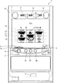
本実施例のスロットマシン1の筐体1aの内部には、図2に示すように、外周に複数種の図柄が配列されたリール2L、2C、2R(以下、左リール、中リール、右リール)が水平方向に並設されており、図1に示すように、これらリール2L、2C、2Rに配列された図柄のうち連続する3つの図柄が前面扉1bに設けられた透視窓3から見えるように配置されている。
Inside the
リール2L、2C、2Rの外周部には、図3に示すように、それぞれ「黒7」、「網7(図中網掛け7)」、「白7」、「BAR」、「リプレイ」、「スイカ」、「黒チェリー」、「白チェリー」、「ベル」、「オレンジ」といった互いに識別可能な複数種類の図柄が所定の順序で、それぞれ21個ずつ描かれている。リール2L、2C、2Rの外周部に描かれた図柄は、透視窓3において各々上中下三段に表示される。
As shown in FIG. 3, on the outer periphery of the
各リール2L、2C、2Rは、各々対応して設けられリールモータ32L、32C、32R(図4参照)によって回転させることで、各リール2L、2C、2Rの図柄が透視窓3に連続的に変化しつつ表示されるとともに、各リール2L、2C、2Rの回転を停止させることで、透視窓3に3つの連続する図柄が表示結果として導出表示されるようになっている。
The
リール2L、2C、2Rの内側には、リール2L、2C、2Rそれぞれに対して、基準位置を検出するリールセンサ33L、33C、33Rと、リール2L、2C、2Rを背面から照射するリールLED55と、が設けられている。また、リールLED55は、リール2L、2C、2Rの連続する3つの図柄に対応する12のLEDからなり、各図柄をそれぞれ独立して照射可能とされている。
Inside the
前面扉1bの各リール2L、2C、2Rの手前側(遊技者側)の位置には、液晶表示器51(図1参照)の表示領域51aが配置されている。液晶表示器51は、液晶素子に対して電圧が印加されていない状態で、透過性を有するノーマリーホワイトタイプの液晶パネルを有しており、表示領域51aの透視窓3に対応する透過領域51b及び透視窓3を介して遊技者側から各リール2L、2C、2Rが視認できるようになっている。また、表示領域51aの透過領域51bを除く領域の裏面には、背後から表示領域51aを照射するバックライト(図示略)が設けられているとともに、さらにその裏面には、内部を隠蔽する隠蔽部材(図示略)が設けられている。
A
前面扉1bには、メダルを投入可能なメダル投入部4、メダルが払い出されるメダル払出口9、クレジット(遊技者所有の遊技用価値として記憶されているメダル数)を用いてメダル1枚分の賭数を設定する際に操作される1枚BETスイッチ5、クレジットを用いて、その範囲内において遊技状態に応じて定められた規定数の賭数のうち最大の賭数を設定する際に操作されるMAXBETスイッチ6、クレジットとして記憶されているメダル及び賭数の設定に用いたメダルを精算する(クレジット及び賭数の設定に用いた分のメダルを返却させる)際に操作される精算スイッチ10、ゲームを開始する際に操作されるスタートスイッチ7、リール2L、2C、2Rの回転を各々停止する際に操作されるストップスイッチ8L、8C、8R、が遊技者により操作可能にそれぞれ設けられている。
On the
また、前面扉1bには、クレジットとして記憶されているメダル枚数が表示されるクレジット表示器11、後述するBB中のメダルの獲得枚数やエラー発生時にその内容を示すエラーコード等が表示される遊技補助表示器12、入賞の発生により払い出されたメダル枚数が表示されるペイアウト表示器13が設けられている。
The
また、前面扉1bには、賭数が1設定されている旨を点灯により報知する1BETLED14、賭数が2設定されている旨を点灯により報知する2BETLED15、賭数が3設定されている旨を点灯により報知する3BETLED16、メダルの投入が可能な状態を点灯により報知する投入要求LED17、スタートスイッチ7の操作によるゲームのスタート操作が有効である旨を点灯により報知するスタート有効LED18、ウェイト(前回のゲーム開始から一定期間経過していないためにリールの回転開始を待機している状態)中である旨を点灯により報知するウェイト中LED19、後述するリプレイゲーム中である旨を点灯により報知するリプレイ中LED20が設けられている。
Further, on the
MAXBETスイッチ6の内部には、1枚BETスイッチ5及びMAXBETスイッチ6の操作による賭数の設定操作が有効である旨を点灯により報知するBETスイッチ有効LED21(図4参照)が設けられており、ストップスイッチ8L、8C、8Rの内部には、該当するストップスイッチ8L、8C、8Rによるリールの停止操作が有効である旨を点灯により報知する左、中、右停止有効LED22L、22C、22R(図4参照)がそれぞれ設けられている。
Inside the
前面扉1bの内側には、所定のキー操作により後述するエラー状態及び後述する打止状態を解除するためのリセット操作を検出するリセットスイッチ23、後述する設定値の変更中や設定値の確認中にその時点の設定値が表示される設定値表示器24、メダル投入部4から投入されたメダルの流路を、筐体1a内部に設けられた後述のホッパータンク34a(図2参照)側またはメダル払出口9側のいずれか一方に選択的に切り替えるための流路切替ソレノイド30、メダル投入部4から投入され、ホッパータンク34a側に流下したメダルを検出する投入メダルセンサ31を有するメダルセレクタ(図示略)、前面扉1bの開放状態を検出するドア開放検出スイッチ25(図4参照)、後述のBB終了時に打止状態(リセット操作がなされるまでゲームの進行が規制される状態)に制御する打止機能の有効/無効を選択するための打止スイッチ36a、後述のBB終了時に自動精算処理(クレジットとして記憶されているメダルを遊技者の操作によらず精算(返却)する処理)に制御する自動精算機能の有効/無効を選択するための自動精算スイッチ36bが設けられている。
Inside the
筐体1a内部には、図2に示すように、前述したリール2L、2C、2R、リールモータ32L、32C、32R、各リール2L、2C、2Rのリール基準位置をそれぞれ検出可能なリールセンサ33L、33C、33R(図4参照)からなるリールユニット2、外部出力信号を出力するための外部出力基板1000、メダル投入部4から投入されたメダルを貯留するホッパータンク34a、ホッパータンク34aに貯留されたメダルをメダル払出口9より払い出すためのホッパーモータ34b、ホッパーモータ34bの駆動により払い出されたメダルを検出する払出センサ34cからなるホッパーユニット34、電源ボックス100が設けられている。
As shown in FIG. 2, a
ホッパーユニット34の側部には、ホッパータンク34aから溢れたメダルが貯留されるオーバーフロータンク35が設けられている。オーバーフロータンク35の内部には、貯留された所定量のメダルを検出可能な高さに設けられた左右に離間する一対の導電部材からなる満タンセンサ35aが設けられており、導電部材がオーバーフロータンク35内に貯留されたメダルを介して接触することにより導電したときに内部に貯留されたメダル貯留量が所定量以上となったこと、すなわちオーバーフロータンクが満タン状態となったことを検出できるようになっている。
On the side of the
電源ボックス100の前面には、設定変更状態または設定確認状態に切り替えるための設定キースイッチ37、通常時においてはエラー状態や前述の打止状態を解除するためのリセットスイッチとして機能し、設定変更状態においては後述する内部抽選の当選確率(出玉率)の設定値を変更するための設定スイッチとして機能するリセット/設定スイッチ38、電源をon/offする際に操作される電源スイッチ39が設けられている。
On the front face of the
また、ドア開放検出スイッチ25は、後述するように設定値を変更する際に操作される設定キースイッチ37、リセット/設定スイッチ38、電源スイッチ39が搭載された電源ボックス100が設けられた側面と対向する側面に設けられている。また、電源ボックス100は、筐体1a内部の下方位置に設けられているのに対し、ドア開放検出スイッチ25は、筐体1a内部の上方位置に設けられている。すなわち、ドア開放検出スイッチ25は、筐体1a内部において、電源ボックス100が設けられている位置に対し、対角する位置に設けられている。
Further, the door opening
尚、ドア開放検出スイッチ25は、電源ボックス100が設けられた側面と対向する側面あるいは電源ボックス100と対角する位置において、前面扉1bの開放状態を検出するものであれば、筐体1aに設けられているものに限らず、前面扉1bの内側に設けられているものであっても良い。
The door
本実施例におけるドア開放検出スイッチ25としては、反射型の光センサを採用している。例えば、光センサは、光(可視光線、赤外線など)を発射する投光部と、該光を検出する受光部とを含み、投光部は所定方向に光を発射し、受光部は投光部から発射された光のうち前面扉1bが閉鎖状態であるときにのみ当該前面扉1bに設けられている反射部材によって反射された光を検出することにより、前面扉1bが閉鎖状態であることを特定可能に構成されている。尚、ドア開放検出スイッチ25は、前面扉1bの開閉状態を検出できるものであれば良く、反射型の光センサに限るものではなく、透過型のものであっても良く、また前面扉1bの開閉状態に応じてON/OFFするスイッチであっても良い。
As the door opening
本実施例のスロットマシン1においてゲームを行う場合には、まず、メダルをメダル投入部4から投入するか、或いはクレジットを使用して賭数を設定する。クレジットを使用するには1枚BETスイッチ5またはMAXBETスイッチ6を操作すれば良い。遊技状態に応じて定められた規定数の賭数が設定されると、入賞ラインL1〜L5(図1参照)が有効となり、スタートスイッチ7の操作が有効な状態、すなわち、ゲームが開始可能な状態となる。尚、遊技状態に対応する規定数のうち最大数を超えてメダルが投入された場合には、その分はクレジットに加算される。
When a game is played in the
入賞ラインとは、各リール2L、2C、2Rの透視窓3に表示された図柄の組み合わせが入賞図柄の組み合わせであるかを判定するために設定されるラインである。本実施例では、図1に示すように、各リール2L、2C、2Rの中段に並んだ図柄に跨って設定された入賞ラインL1、各リール2L、2C、2Rの上段に並んだ図柄に跨って設定された入賞ラインL2、各リール2L、2C、2Rの下段に並んだ図柄に跨って設定された入賞ラインL3、リール2Lの上段、リール2Cの中段、リール2Rの下段、すなわち右下がりに並んだ図柄に跨って設定された入賞ラインL4、リール2Lの下段、リール2Cの中段、リール2Rの上段、すなわち右上がりに並んだ図柄に跨って設定された入賞ラインL5の5種類が入賞ラインとして定められている。
The winning line is a line that is set to determine whether a combination of symbols displayed on the
ゲームが開始可能な状態でスタートスイッチ7を操作すると、各リール2L、2C、2Rが回転し、各リール2L、2C、2Rの図柄が連続的に変動する。この状態でいずれかのストップスイッチ8L、8C、8Rを操作すると、対応するリール2L、2C、2Rの回転が停止し、透視窓3に表示結果が導出表示される。
When the
そして全てのリール2L、2C、2Rが停止されることで1ゲームが終了し、有効化されたいずれかの入賞ラインL1〜L5上に予め定められた図柄の組み合わせ(以下、役とも呼ぶ)が各リール2L、2C、2Rの表示結果として停止した場合には入賞が発生し、その入賞に応じて定められた枚数のメダルが遊技者に対して付与され、クレジットに加算される。また、クレジットが上限数(本実施例では50)に達した場合には、メダルが直接メダル払出口9(図1参照)から払い出されるようになっている。尚、有効化された複数の入賞ライン上にメダルの払出を伴う図柄の組み合わせが揃った場合には、有効化された入賞ラインに揃った図柄の組み合わせそれぞれに対して定められた払出枚数を合計し、合計した枚数のメダルが遊技者に対して付与されることとなる。ただし、1ゲームで付与されるメダルの払出枚数には、上限(本実施例では15枚)が定められており、合計した払出枚数が上限を超える場合には、上限枚数のメダルが付与されることとなる。また、有効化されたいずれかの入賞ラインL1〜L5上に、遊技状態の移行を伴う図柄の組み合わせが各リール2L、2C、2Rの表示結果として停止した場合には図柄の組み合わせに応じた遊技状態に移行するようになっている。
Then, when all the
図4は、スロットマシン1の構成を示すブロック図である。スロットマシン1には、図4に示すように、遊技制御基板40、演出制御基板90、電源基板101が設けられており、遊技制御基板40によって遊技状態が制御され、演出制御基板90によって遊技状態に応じた演出が制御され、電源基板101によってスロットマシン1を構成する電気部品の駆動電源が生成され、各部に供給される。
FIG. 4 is a block diagram showing a configuration of the
電源基板101には、外部からAC100Vの電源が供給されるとともに、このAC100Vの電源からスロットマシン1を構成する電気部品の駆動に必要な直流電圧が生成され、遊技制御基板40及び遊技制御基板40を介して接続された演出制御基板90に供給されるようになっている。また、後述するメイン制御部41からサブ制御部91へのコマンド伝送ラインと、遊技制御基板40から演出制御基板90に対して電源を供給する電源供給ラインと、が一系統のケーブル及びコネクタを介して接続されており、これらケーブルと各基板とを接続するコネクタ同士が全て接続されることで演出制御基板90側の各部が動作可能となり、かつメイン制御部41からのコマンドを受信可能な状態となる。このため、メイン制御部41からコマンドを伝送するコマンド伝送ラインが演出制御基板90に接続されている状態でなければ、演出制御基板90側に電源が供給されず、演出制御基板90側のみが動作してしまうことがない。
The
また、電源基板101には、前述したホッパーモータ34b、払出センサ34c、満タンセンサ35a、設定キースイッチ37、リセット/設定スイッチ38、電源スイッチ39が接続されている。
Further, the above-described
遊技制御基板40には、前述した1枚BETスイッチ5、MAXBETスイッチ6、スタートスイッチ7、ストップスイッチ8L、8C、8R、精算スイッチ10、リセットスイッチ23、投入メダルセンサ31、ドア開放検出スイッチ25、打止スイッチ36a、自動精算スイッチ36b、リールセンサ33L、33C、33Rが接続されているとともに、電源基板101を介して前述した払出センサ34c、満タンセンサ35a、設定キースイッチ37、リセット/設定スイッチ38が接続されており、これら接続されたスイッチ類の検出信号が入力されるようになっている。
On the
また、遊技制御基板40には、前述したクレジット表示器11、遊技補助表示器12、ペイアウト表示器13、1〜3BETLED14〜16、投入要求LED17、スタート有効LED18、ウェイト中LED19、リプレイ中LED20、BETスイッチ有効LED21、左、中、右停止有効LED22L、22C、22R、設定値表示器24、流路切替ソレノイド30、リールモータ32L、32C、32Rが接続されているとともに、電源基板101を介して前述したホッパーモータ34bが接続されており、これら電気部品は、遊技制御基板40に搭載された後述のメイン制御部41の制御に基づいて駆動されるようになっている。
Further, the
遊技制御基板40には、メイン制御部41、制御用クロック生成回路42、乱数用クロック生成回路43、スイッチ検出回路44、モータ駆動回路45、ソレノイド駆動回路46、LED駆動回路47、電断検出回路48、リセット回路49が搭載されている。
The
メイン制御部41は、1チップマイクロコンピュータにて構成され、後述するROM506に記憶された制御プログラムを実行して、遊技の進行に関する処理を行うととともに、遊技制御基板40に搭載された制御回路の各部を直接的または間接的に制御する。
The
制御用クロック生成回路42は、メイン制御部41の外部にて、所定周波数の発振信号となる制御用クロックCCLKを生成する。制御用クロック生成回路42により生成された制御用クロックCCLKは、例えば図5に示すようなメイン制御部41の制御用外部クロック端子EXCを介してクロック回路502に供給される。乱数用クロック生成回路43は、メイン制御部41の外部にて、制御用クロックCCLKの発振周波数とは異なる所定周波数の発振信号となる乱数用クロックRCLKを生成する。乱数用クロック生成回路43により生成された乱数用クロックRCLKは、例えば図5に示すようなメイン制御部41の乱数用外部クロック端子ERCを介して乱数回路509に供給される。
The control
スイッチ検出回路44は、遊技制御基板40に直接または電源基板101を介して接続されたスイッチ類から入力された検出信号を取り込んでメイン制御部41に伝送する。モータ駆動回路45は、メイン制御部41から出力されたモータ駆動信号をリールモータ32L、32C、32Rに伝送する。ソレノイド駆動回路46は、メイン制御部41から出力されたソレノイド駆動信号を流路切替ソレノイド30に伝送する。LED駆動回路は、メイン制御部41から出力されたLED駆動信号を遊技制御基板40に接続された各種表示器やLEDに伝送する。電断検出回路48は、スロットマシン1に供給される電源電圧を監視し、電圧低下を検出したときに、その旨を示す電圧低下信号をメイン制御部41に対して出力する。リセット回路49は、電源投入時または電源遮断時などの電源が不安定な状態においてメイン制御部41にシステムリセット信号を与える。また、リセット回路49は、ウォッチドッグタイマを内蔵し、ウォッチドッグタイマがタイムアップした場合、すなわちメイン制御部41のCPU505の動作が一定時間停止した場合においてメイン制御部41にユーザリセット信号を与える。
The
図5は、遊技制御基板40に搭載されたメイン制御部41の構成例を示している。図5に示すメイン制御部41は、1チップマイクロコンピュータであり、外部バスインタフェース501と、クロック回路502と、固有情報記憶回路503と、リセット/割込コントローラ504と、CPU505と、ROM506と、RAM507と、CTC(カウンタ/タイマサーキット)508と、乱数回路509と、PIP(パラレルインプットポート)510と、シリアル通信回路511と、アドレスデコード回路512とを備えて構成される。
FIG. 5 shows a configuration example of the
図5に示すメイン制御部41が備える外部バスインタフェース501は、メイン制御部41を構成するチップの外部バスと内部バスとのインタフェース機能や、アドレスバス、データバス及び各制御信号の方向制御機能などを有するバスインタフェースである。例えば、外部バスインタフェース501は、メイン制御部41に外付けされた外部メモリや外部入出力装置などに接続され、これらの外部装置との間でアドレス信号やデータ信号、各種の制御信号などを送受信するものであれば良い。この実施の形態において、外部バスインタフェース501には、内部リソースアクセス制御回路501Aが含まれている。
The
内部リソースアクセス制御回路501Aは、外部バスインタフェース501を介した外部装置からメイン制御部41の内部データに対するアクセスを制御して、例えばROM506に記憶されたゲーム制御用プログラムや固定データといった、内部データの不適切な外部読出を制限するための回路である。
The internal resource
メイン制御部41が備えるクロック回路502は、例えば制御用外部クロック端子EXCに入力される発振信号を2分周することなどにより、内部システムクロックSCLKを生成する回路である。本実施例では、制御用外部クロック端子EXCに制御用クロック生成回路42が生成した制御用クロックCCLKが入力される。クロック回路502により生成された内部システムクロックSCLKは、例えばCPU505といった、メイン制御部41において遊技の進行を制御する各種回路に供給される。また、内部システムクロックSCLKは、乱数回路509にも供給され、乱数用クロック生成回路43から供給される乱数用クロックRCLKの周波数を監視するために用いられる。
The
メイン制御部41が備える固有情報記憶回路503は、例えばメイン制御部41の内部情報となる複数種類の固有情報を記憶する回路である。
The unique
メイン制御部41が備えるリセット/割込コントローラ504は、メイン制御部41の内部や外部にて発生する各種リセット、割込要求を制御するためのものである。リセット/割込コントローラ504が制御するリセットには、システムリセットとユーザリセットが含まれている。システムリセットは、外部システムリセット端子XSRSTに一定の期間にわたりローレベル信号(システムリセット信号)が入力されたときに発生するリセットである。ユーザリセットは、外部ユーザリセット端子XURSTに一定の期間にわたりローレベルの信号(ユーザリセット信号)が入力されたとき、または内蔵ウォッチドッグタイマ(WDT)のタイムアウト信号が発生したことや、指定エリア外走行禁止(IAT)が発生したことなど、所定の要因により発生するリセットである。尚、本実施例では前述のように内蔵ウォッチドッグタイマを使用せずにリセット回路49に搭載されたウォッチドッグタイマ(WDT)を用いているため、外部ユーザリセット端子XURSTにユーザリセット信号が入力されるか、指定エリア外走行禁止(IAT)が発生することでユーザリセットが発生することとなる。
The reset / interrupt
リセット/割込コントローラ504が制御する割込には、ノンマスカブル割込NMIとマスカブル割込INTが含まれている。ノンマスカブル割込NMIは、CPU505の割込禁止状態でも無条件に受け付けられる割込であり、外部ノンマスカブル割込端子XNMI(入力ポートP4と兼用)に一定の期間にわたりローレベル信号が入力されたときに発生する割込である。マスカブル割込INTは、CPU505の設定命令により、割込要求の受け付けを許可/禁止できる割込であり、優先順位設定による多重割込の実行が可能である。マスカブル割込INTの要因としては、外部マスカブル割込端子XINT(入力ポートP3と兼用)に一定の期間にわたりローレベル信号が入力されたこと、CTC508に含まれるタイマ回路にてタイムアウトが発生したこと、シリアル通信回路511にてデータ送信による割込要因が発生したこと、乱数回路509にて乱数値となる数値データの取込による割込要因が発生したことなど、複数種類の割込要因が予め定められていれば良い。
Interrupts controlled by the reset / interrupt
メイン制御部41が備えるCPU505は、ROM506から読み出したプログラムを実行することにより、スロットマシン1におけるゲームの進行を制御するための処理などを実行する。このときには、CPU505がROM506から固定データを読み出す固定データ読出動作や、CPU505がRAM507に各種の変動データを書き込んで一時記憶させる変動データ書込動作、CPU505がRAM507に一時記憶されている各種の変動データを読み出す変動データ読出動作、CPU505が外部バスインタフェース501やPIP510などを介してメイン制御部41の外部から各種信号の入力を受け付ける受信動作、CPU505が外部バスインタフェース501やシリアル通信回路511などを介してメイン制御部41の外部へと各種信号を出力する送信動作等も行われる。
The
このように、メイン制御部41では、CPU505がROM506に格納されているプログラムに従って制御を実行するので、以下、メイン制御部41(又はCPU505)が実行する(又は処理を行う)ということは、具体的には、CPU505がプログラムに従って制御を実行することである。このことは、遊技制御基板40以外の他の基板に搭載されているマイクロコンピュータについても同様である。
As described above, in the
メイン制御部41が備えるROM506には、ゲーム制御用のユーザプログラムや固定データ等が記憶されている。また、ROM506には、セキュリティチェックプログラム506Aが記憶されている。CPU505は、スロットマシン1の電源投入やシステムリセットの発生に応じてメイン制御部41がセキュリティモードに移行したときに、ROM506に記憶されたセキュリティチェックプログラム506Aを読み出し、ROM506の記憶内容が変更されたか否かを検査するセキュリティチェック処理を実行する。尚、セキュリティチェックプログラム506Aは、ROM506とは異なる内蔵メモリに記憶されても良い。また、セキュリティチェックプログラム506Aは、例えば外部バスインタフェース501を介してメイン制御部41に外付けされた外部メモリの記憶内容を検査するセキュリティチェック処理に対応したものであっても良い。
A
メイン制御部41が備えるRAM507は、ゲーム制御用のワークエリアを提供する。ここで、RAM507の少なくとも一部は、バックアップ電源によってバックアップされているバックアップRAMであれば良い。すなわち、スロットマシンへの電力供給が停止しても、所定期間はRAM507の少なくとも一部の内容が保存される。尚、本実施例では、RAM507の全ての領域がバックアップRAMとされており、スロットマシンへの電力供給が停止しても、所定期間はRAM507の全ての内容が保存される。
A RAM 507 provided in the
メイン制御部41が備えるCTC508は、例えば8ビットのプログラマブルタイマを3チャネル(PTC0−PTC2)内蔵して構成され、リアルタイム割込の発生や時間計測を可能とするタイマ回路を含んでいる。各プログラマブルタイマPTC0−PTC2は、内部システムクロックSCLKに基づいて生成されたカウントクロックの信号変化(例えばハイレベルからローレベルへと変化する立下りタイミング)などに応じて、タイマ値が更新されるものであれば良い。また、CTC508は、例えば8ビットのプログラマブルカウンタを4チャネル(PCC0−PCC3)内蔵しても良い。各プログラマブルカウンタPCC0−PCC3は、内部システムクロックSCLKの信号変化、或いは、プログラマブルカウンタPCC0−PCC3のいずれかにおけるタイムアウトの発生などに応じて、カウント値が更新されるものであれば良い。CTC508は、セキュリティ時間を延長する際の延長時間(可変設定時間)をシステムリセット毎にランダムに決定するために用いられるフリーランカウンタや、乱数回路509にて生成される乱数のスタート値をシステムリセット毎にランダムに決定するために用いられるフリーランカウンタなどを、含んでも良い。或いは、これらのフリーランカウンタは、例えばRAM507のバックアップ領域といった、CTC508とは異なるメイン制御部41の内部回路に含まれても良い。
The
メイン制御部41が備える乱数回路509は、例えば16ビット乱数といった、所定の更新範囲を有する乱数値となる数値データを生成する回路である。本実施例では、遊技制御基板40の側において、後述する内部抽選用の乱数値を示す数値データがカウント可能に制御される。尚、遊技効果を高めるために、これら以外の乱数値が用いられても良い。CPU505は、乱数回路509から抽出した数値データに基づき、乱数回路509とは異なるランダムカウンタを用いて、ソフトウェアによって各種の数値データを加工或いは更新することで、内部抽選用の乱数値を示す数値データをカウントするようにしても良い。以下では、内部抽選用の乱数値を示す数値データが、ハードウェアとなる乱数回路509からCPU505により抽出された数値データをソフトウェアにより加工しないものとする。尚、乱数回路509は、メイン制御部41に内蔵されるものであっても良いし、メイン制御部41とは異なる乱数回路チップとして、メイン制御部41に外付けされるものであっても良い。
A
内部抽選用の乱数値は、複数種類の入賞について発生を許容するか否かを判定するために用いられる値であり、本実施例では、「0」〜「65535」の範囲の値をとる。 The random number for internal lottery is a value used to determine whether or not to allow a plurality of types of winnings, and takes a value in the range of “0” to “65535” in this embodiment.
メイン制御部41が備えるPIP510は、例えば6ビット幅の入力専用ポートであり、専用端子となる入力ポートP0〜入力ポートP2と、機能兼用端子となる入力ポートP3〜入力ポートP5とを含んでいる。入力ポートP3は、CPU505等に接続される外部マスカブル割込端子XINTと兼用される。入力ポートP4は、CPU505等に接続される外部ノンマスカブル割込端子XNMIと兼用される。入力ポートP5は、シリアル通信回路511が使用する第1チャネル受信端子RXAと兼用される。
The
図5に示すメイン制御部41が備えるアドレスデコード回路512は、メイン制御部41の内部における各機能ブロックのデコードや、外部装置用のデコード信号であるチップセレクト信号のデコードを行うための回路である。チップセレクト信号により、メイン制御部41の内部回路、或いは、周辺デバイスとなる外部装置を、選択的に有効動作させて、CPU505からのアクセスが可能となる。
An address decoding circuit 512 provided in the
メイン制御部41が備えるROM506には、ゲーム制御用のユーザプログラムやセキュリティチェックプログラム506Aの他に、ゲームの進行を制御するために用いられる各種の選択用データ、テーブルデータなどが格納される。例えば、ROM506には、CPU505が各種の判定や決定、設定を行うために用意された複数の判定テーブルや決定テーブル、設定テーブルなどを構成するデータが記憶されている。また、ROM506には、CPU505が遊技制御基板40から各種の制御コマンドとなる制御信号を送信するために用いられる複数のコマンドテーブルを構成するテーブルデータなどが記憶されている。
The
メイン制御部41が備えるRAM507には、スロットマシン1におけるゲームの進行を制御するために用いられる各種のデータを保持する領域として、遊技制御用データ保持エリア590が設けられている。RAM507としては、例えばDRAMが使用されており、記憶しているデータ内容を維持するためのリフレッシュ動作が必要になる。CPU505には、このリフレッシュ動作を行うためのリフレッシュレジスタが内蔵されている。例えば、リフレッシュレジスタは8ビットからなり、そのうち下位7ビットはCPU505がROM506から命令フェッチするごとに自動的にインクリメントされる。したがって、リフレッシュレジスタにおける格納値の更新は、CPU505における1命令の実行時間ごとに行われることになる。
The RAM 507 provided in the
メイン制御部41は、シリアル通信回路511を介してサブ制御部91に各種のコマンドを送信する。メイン制御部41からサブ制御部91へ送信されるコマンドは一方向のみで送られ、サブ制御部91からメイン制御部41へ向けてコマンドが送られることはない。
The
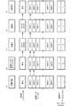
シリアル通信回路511は、図6に示すように、データレジスタ560、送信データレジスタ561、送信用シフトレジスタ562、ステータスレジスタ563を備える。
As shown in FIG. 6, the
データレジスタ560は、CPU505が生成し、内部バスを介して転送されたコマンドデータを一時的にバッファするレジスタであり、データレジスタ560にバッファされたコマンドデータは送信データレジスタ561の空き領域に格納される。
The data register 560 is a register for temporarily buffering command data generated by the
送信データレジスタ561は、送信待ちのコマンドデータが格納されるレジスタである。送信データレジスタ561には、複数のコマンドデータを格納可能な領域が設けられており、最大で32バイトのコマンドデータを格納可能とされている。 The transmission data register 561 is a register that stores command data waiting for transmission. The transmission data register 561 is provided with an area capable of storing a plurality of command data, and can store a maximum of 32 bytes of command data.
送信用シフトレジスタ562は、シリアルデータ化されたコマンドデータが格納されるレジスタであり、送信データレジスタ561に格納されているコマンドデータのうち最も早い段階で格納されたコマンドデータからシリアルデータに変換され、送信用シフトレジスタ562に格納される。そして、送信用シフトレジスタ562にコマンドデータが格納されると直ちにサブ制御部91に対して転送されるようになっている。
The
ステータスレジスタ563は、コマンドデータを送信中か否かを示す送信完了、送信データレジスタ561にコマンドデータが格納されているか否かを示すデータエンプティ等、シリアル通信回路511の送信状態を示すデータが格納されるレジスタである。送信完了の値として“1”が格納されている場合には、コマンドデータの送信を行っていないか、コマンドデータの送信が完了した旨を示し、“0”が格納されている場合には、コマンドデータの送信中、またはコマンドデータの送信待ちである旨を示す。データエンプティの値として“1”が設定されている場合には、送信データレジスタ561に1以上の送信待ちのコマンドデータが格納されている旨を示し、“0”が格納されている場合には、送信データレジスタ561に送信待ちのコマンドデータが格納されていない旨を示す。
The status register 563 stores data indicating the transmission state of the
ステータスレジスタ563の値は、内部バスを介してCPU505が参照可能であり、CPU505は、ステータスレジスタ563の値を読み出すことにより、シリアル通信回路511の送信状態を確認できるようになっている。
The value of the
次にシリアル通信回路511の動作状況を図7に基づいて説明する。
Next, the operation status of the
まず、送信データレジスタ561の全ての領域が空の状態であり、送信用シフトレジスタ562によるコマンドデータの送信も行われていない場合には、図7(a)に示すように、送信完了、データエンプティの値は、ともに“1”が設定されている。
First, when all the areas of the transmission data register 561 are empty and no command data is transmitted by the
図7(b)に示すように、CPU505の転送指令によりコマンドデータ1、2が送信データレジスタ561に格納されると、送信完了、データエンプティの値は、ともに“0”に変化する。
As shown in FIG. 7B, when the
次いで、図7(c)(d)に示すように、送信データレジスタ561に格納されたコマンドデータ1、2のうち先に格納されたコマンドデータ1がシリアルデータに変換され、送信用シフトレジスタ562によってサブ制御部91に対して送信され、コマンドデータ1の送信が完了すると、次に格納されたコマンドデータ2がシリアルデータに変換され、送信用シフトレジスタ562によってサブ制御部91に対して送信されるとともに、最後のコマンドデータがシリアルデータに変換され、送信用シフトレジスタ562に格納され、送信データレジスタ561が空になるとデータエンプティの値が“1”に変化し、図7(e)に示すように、送信用シフトレジスタ562に格納されている最後のコマンドデータの送信も完了すると、送信完了の値も“1”に変化し、全てのコマンドデータの送信が完了した状態となる。
Next, as shown in FIGS. 7C and 7D, the
メイン制御部41は、遊技制御基板40に接続された各種スイッチ類の検出状態が入力ポートから入力される。そしてメイン制御部41は、これら入力ポートから入力される各種スイッチ類の検出状態に応じて段階的に移行する基本処理を実行する。
The
また、メイン制御部41は、割込の発生により基本処理に割り込んで割込処理を実行できるようになっている。本実施例では、CTC508に含まれるタイマ回路にてタイムアウトが発生したこと、すなわち一定時間間隔(本実施例では、約0.56ms)毎に後述するタイマ割込処理(メイン)を実行する。
Further, the
また、メイン制御部41は、割込処理の実行中に他の割込を禁止するように設定されているとともに、複数の割込が同時に発生した場合には、予め定められた順位によって優先して実行する割込が設定されている。尚、割込処理の実行中に他の割込要因が発生し、割込処理が終了してもその割込要因が継続している状態であれば、その時点で新たな割込が発生することとなる。
The
メイン制御部41は、基本処理として遊技制御基板40に接続された各種スイッチ類の検出状態が変化するまでは制御状態に応じた処理を繰り返しループし、各種スイッチ類の検出状態の変化に応じて段階的に移行する処理を実行する。また、メイン制御部41は、一定時間間隔(本実施例では、約0.56ms)毎にタイマ割込処理(メイン)を実行する。尚、タイマ割込処理(メイン)の実行間隔は、基本処理において制御状態に応じて繰り返す処理が一巡する時間とタイマ割込処理(メイン)の実行時間とを合わせた時間よりも長い時間に設定されており、今回と次回のタイマ割込処理(メイン)との間で必ず制御状態に応じて繰り返す処理が最低でも一巡することとなる。
The
演出制御基板90には、スロットマシン1の前面扉1bに配置された液晶表示器51(図1参照)、演出効果LED52、スピーカ53、54、前述したリールLED55等の演出装置が接続されており、これら演出装置は、演出制御基板90に搭載された後述のサブ制御部91による制御に基づいて駆動されるようになっている。
The
尚、本実施例では、演出制御基板90に搭載されたサブ制御部91により、液晶表示器51、演出効果LED52、スピーカ53、54、リールLED55等の演出装置の出力制御が行われる構成であるが、サブ制御部91とは別に演出装置の出力制御を直接的に行う出力制御部を演出制御基板90または他の基板に搭載し、サブ制御部91がメイン制御部41からのコマンドに基づいて演出装置の出力パターンを決定し、サブ制御部91が決定した出力パターンに基づいて出力制御部が演出装置の出力制御を行う構成としても良く、このような構成では、サブ制御部91及び出力制御部の双方によって演出装置の出力制御が行われることとなる。
In this embodiment, the
また、本実施例では、演出装置として液晶表示器51、演出効果LED52、スピーカ53、54、リールLED55を例示しているが、演出装置は、これらに限られず、例えば、機械的に駆動する表示装置や機械的に駆動する役モノなどを演出装置として適用しても良い。
Further, in the present embodiment, the
演出制御基板90には、サブCPU91a、ROM91b、RAM91c、I/Oポート91dなどを備えたマイクロコンピュータにて構成され、演出の制御を行うサブ制御部91、演出制御基板90に接続された液晶表示器51の表示制御を行う表示制御回路92、演出効果LED52、リールLED55の駆動制御を行うLED駆動回路93、スピーカ53、54からの音声出力制御を行う音声出力回路94、電源投入時または電源遮断時にサブCPU91aにリセット信号を与えるリセット回路95、日付情報及び時刻情報を含む時間情報を出力する時計装置97、スロットマシン1に供給される電源電圧を監視し、電圧低下を検出したときに、その旨を示す電圧低下信号をサブ制御部91に対して出力する電断検出回路98が搭載されており、サブ制御部91は、メイン制御部から送信されるコマンドを受けて、演出を行うための各種の制御を行うとともに、演出制御基板90に搭載された制御回路の各部を直接的または間接的に制御する。
The
リセット回路95は、遊技制御基板40においてメイン制御部41にシステムリセット信号を与えるリセット回路49よりもリセット信号を解除する電圧が低く定められており、電源投入時においてサブ制御部91は、メイン制御部41よりも早い段階で起動するようになっている。一方で、電断検出回路98は、遊技制御基板40においてメイン制御部41に電圧低下信号を出力する電断検出回路48よりも電圧低下信号を出力する電圧が低く定められており、電断時においてサブ制御部91は、メイン制御部41よりも遅い段階で停電を検知し、後述する電断処理(サブ)を行うこととなる。
The
サブ制御部91は、メイン制御部41と同様に、割込機能を備えており、メイン制御部41からのコマンド受信時に割込を発生させて、メイン制御部41から送信されたコマンドを取得し、バッファに格納するコマンド受信割込処理を実行する。また、サブ制御部91は、システムクロックの入力数が一定数に到達する毎、すなわち一定間隔毎に割込を発生させて後述するタイマ割込処理(サブ)を実行する。
Similar to the
また、サブ制御部91は、メイン制御部41とは異なり、コマンドの受信に基づいて割込が発生した場合には、タイマ割込処理(サブ)の実行中であっても、当該処理に割り込んでコマンド受信割込処理を実行し、タイマ割込処理(サブ)の契機となる割込が同時に発生してもコマンド受信割込処理を最優先で実行するようになっている。
Also, unlike the
また、サブ制御部91にも、停電時においてバックアップ電源が供給されており、バックアップ電源が供給されている間は、RAM91cに記憶されているデータが保持されるようになっている。
The
本実施例のスロットマシン1は、設定値に応じてメダルの払出率が変わるものである。詳しくは、後述する内部抽選において設定値に応じた当選確率を用いることにより、メダルの払出率が変わるようになっている。設定値は1〜6の6段階からなり、6が最も払出率が高く、5、4、3、2、1の順に値が小さくなるほど払出率が低くなる。すなわち設定値として6が設定されている場合には、遊技者にとって最も有利度が高く、5、4、3、2、1の順に値が小さくなるほど有利度が段階的に低くなる。
In the
設定値を変更するためには、前面扉1bを開放させ、筐体1a内に設けられている電源ボックス100の電源スイッチ39および設定キースイッチ37を操作して、スロットマシン1の電源がON状態である場合には一旦OFF状態にし、設定キースイッチ37をON状態としてからスロットマシン1の電源をONする必要がある。設定キースイッチ37をON状態として電源をONすると、設定値表示器24にRAM507から読み出された設定値が表示値として表示され、リセット/設定スイッチ38の操作による設定値の変更操作が可能な設定変更状態に移行する。設定変更状態において、リセット/設定スイッチ38が操作されると、設定値表示器24に表示された表示値が1ずつ更新されていく(設定6からさらに操作されたときは、設定1に戻る)。そして、スタートスイッチ7が操作されると表示値を設定値として確定する。そして、設定キースイッチ37がOFFされると、確定した表示値(設定値)がメイン制御部41のRAM507に格納され、遊技の進行が可能な状態に移行する。尚、電源スイッチ39を一旦OFF状態にし、設定キースイッチ37をON状態として電源スイッチ39をONさせる操作を行うことにより、設定変更状態に移行されるため、当該操作をまとめて設定変更操作ともいう。
In order to change the set value, the
本実施例においては、前面扉1bを開放状態とすることにより設定変更操作を行うことが可能となるため、当該前面扉1bが開閉体であるといえる。また、前面扉1bの開放状態を検出するためのドア開放検出スイッチ25が開閉状態検出手段であるといえる。
In the present embodiment, since the setting change operation can be performed by opening the
また、設定値を確認するためには、ゲーム終了後、賭数が設定されていない状態で設定キースイッチ37をon状態とすれば良い。このような状況で設定キースイッチ37をon状態とすると、設定値表示器24にRAM507から読み出された設定値が表示されることで設定値を確認可能な設定確認状態に移行する。設定確認状態においては、ゲームの進行が不能であり、設定キースイッチ37をoff状態とすることで、設定確認状態が終了し、ゲームの進行が可能な状態に復帰することとなる。
In order to check the set value, after the game is over, the setting
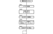
本実施例のスロットマシン1においては、メイン制御部41は、タイマ割込処理(メイン)を実行する毎に、電断検出回路48からの電圧低下信号が検出されているか否かを判定する停電判定処理を行い、停電判定処理において電圧低下信号が検出されていると判定した場合に、電断処理(メイン)を実行する。電断処理(メイン)では、レジスタを後述するRAM507のスタックに退避し、RAM507にいずれかのビットが1となる破壊診断用データ(本実施例では、5AH)、すなわち0以外の特定のデータを格納するとともに、RAM507の全ての領域に格納されたデータに基づくRAMパリティが0となるようにRAMパリティ調整用データを計算し、RAM507に格納する処理を行うようになっている。尚、RAMパリティとはRAM507の該当する領域(本実施例では、全ての領域)の各ビットに格納されている値の排他的論理和として算出される値である。このため、RAM507の全ての領域に格納されたデータに基づくRAMパリティが0であれば、RAMパリティ調整用データは0となり、RAM507の全ての領域に格納されたデータに基づくRAMパリティが1であれば、RAMパリティ調整用データは1となる。
In the
そして、メイン制御部41は、システムリセットによるかユーザリセットによるかに関わらず、その起動時においてRAM507の全ての領域に格納されたデータに基づいてRAMパリティを計算するとともに、破壊診断用データの値を確認し、RAMパリティが0であり、かつ破壊診断用データの値も正しいことを条件に、RAM507に記憶されているデータに基づいてメイン制御部41の処理状態を電断前の状態に復帰させるが、RAMパリティが0でない場合(1の場合)や破壊診断用データの値が正しくない場合には、RAM異常と判定し、RAM異常エラーコードをレジスタにセットしてRAM異常エラー状態に制御し、遊技の進行を不能化させるようになっている。尚、RAM異常エラー状態は、通常のエラー状態と異なり、リセットスイッチ23やリセット/設定スイッチ38を操作しても解除されないようになっており、前述した設定変更状態において新たな設定値が設定されるまで解除されることがない。
The
尚、本実施例では、RAM507に格納されている全てのデータが停電時においてもバックアップ電源により保持されるとともに、メイン制御部41は、電源投入時においてRAM507のデータが正常であると判定した場合に、RAM507の格納データに基づいて電断前の制御状態に復帰する構成であるが、RAM507に格納されているデータのうち停電時において制御状態の復帰に必要なデータのみをバックアップし、電源投入時においてバックアップされているデータに基づいて電断前の制御状態に復帰する構成としても良い。
In this embodiment, all data stored in the RAM 507 is held by the backup power source even in the event of a power failure, and the
また、電源投入時において電断前の制御状態に復帰させる際に、全ての制御状態を電断前の制御状態に復帰させる必要はなく、遊技者に対して不利益とならない最低限の制御状態を復帰させる構成であれば良く、例えば、入力ポートの状態などを全て電断前の状態に復帰させる必要はない。 In addition, when returning to the control state before the power interruption when the power is turned on, it is not necessary to return all the control states to the control state before the power interruption, and the minimum control state that does not disadvantage the player For example, it is not necessary to restore the state of all input ports to the state before power interruption.
また、サブ制御部91もタイマ割込処理(サブ)において電断検出回路98からの電圧低下信号が検出されているか否かを判定し、電圧低下信号が検出されていると判定した場合に電断処理(サブ)を実行する。電断処理(サブ)では、レジスタを後述するRAM91cのスタックに退避し、RAM91cにいずれかのビットが1となる破壊診断用データを格納するとともに、RAM91cの全ての領域に格納されたデータに基づくRAMパリティが0となるようにRAMパリティ調整用データを計算し、RAM91cに格納する処理を行うようになっている。
The
そして、サブ制御部91は、その起動時においてRAM91cの全ての領域に格納されたデータに基づいてRAMパリティを計算し、RAMパリティが0であることを条件に、RAM91cに記憶されているデータに基づいてサブ制御部91の処理状態を電断前の状態に復帰させるが、RAMパリティが0でない場合(1の場合)には、RAM異常と判定し、RAM91cを初期化するようになっている。この場合、メイン制御部41と異なり、RAM91cが初期化されるのみで演出の実行が不能化されることはない。
Then, the
尚、本実施例では、RAM91cに格納されている全てのデータが停電時においてもバックアップ電源により保持されるとともに、サブ制御部91は、電源投入時においてRAM91cのデータが正常であると判定した場合に、RAM91cの格納データに基づいて電断前の制御状態に復帰する構成であるが、RAM91cに格納されているデータのうち停電時において制御状態の復帰に必要なデータのみをバックアップし、電源投入時においてバックアップされているデータに基づいて電断前の制御状態に復帰する構成としても良い。
In this embodiment, all data stored in the
また、電源投入時において電断前の制御状態に復帰させる際に、全ての制御状態を電断前の制御状態に復帰させる必要はなく、遊技者に対して不利益とならない最低限の制御状態を復帰させる構成であれば良く、入力ポートの状態や、演出が途中で中断された場合の途中経過などを全て電断前の状態に復帰させる必要はない。 In addition, when returning to the control state before the power interruption when the power is turned on, it is not necessary to return all the control states to the control state before the power interruption, and the minimum control state that does not disadvantage the player It is not necessary to restore the state of the input port or the progress in the middle of the production when it is interrupted.
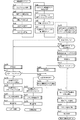
次に、メイン制御部41のRAM507の初期化について説明する。メイン制御部41のRAM507の格納領域は、重要ワーク、一般ワーク、特別ワーク、設定値ワーク、非保存ワーク、非初期化領域、未使用領域、スタック領域に区分されている。
Next, initialization of the RAM 507 of the
重要ワークは、各種表示器やLEDの表示用データ、I/Oの入出力データ、遊技時間の計時カウンタ等、BB終了時に初期化すると不都合があるデータが格納されるワークである。一般ワークは、停止制御テーブル、停止図柄、メダルの払出枚数、BB中のメダル払出総数等、BB終了時に初期化可能なデータが格納されるワークである。特別ワークは、各種ソフトウェア乱数等、設定開始前にのみ初期化されるデータが格納されるワークである。非保存ワークは、各種スイッチ類の状態を保持するワークであり、起動時にRAM507のデータが破壊されているか否かに関わらず必ず値が設定されることとなる。非初期化ワークは、RAM異常エラーや設定変更時にも初期化されないデータが格納されるワークである。非初期化ワークには、さらに内部抽選処理で抽選を行う際に用いる設定値が格納される設定値ワーク、演出制御基板90へ送信されるコマンドが一時的に格納されるコマンドバッファ(コマンドバッファ内のコマンドは次回コマンドが格納されるまで維持されるので、最後に送信されたコマンドが常に格納されることとなる)、外部出力基板1000に対して出力されるメダルIN信号、メダルOUT信号、RB中信号、BB中信号、ドア開放信号、設定変更信号、投入エラー信号、払出エラー信号のうち外部出力基板1000から出力されるセキュリティ信号を構成するドア開放信号、設定変更信号、投入エラー信号、払出エラー信号の出力状態(on/offの状態)が格納されるセキュリティワークが割り当てられている。未使用領域は、RAM507の格納領域のうち使用していない領域であり、後述する複数の初期化条件のいずれか1つでも成立すれば初期化されることとなる。スタック領域は、メイン制御部41のレジスタから退避したデータが格納される領域であり、このうちの未使用スタック領域は、未使用領域と同様に、後述する複数の初期化条件のいずれか1つでも成立すれば初期化されることとなるが、使用中スタック領域は、プログラムの続行のため、初期化されることはない。
The important work is a work in which data which is inconvenient if it is initialized at the end of the BB, such as various display devices, LED display data, I / O input / output data, and game time counter. The general work is a work that stores data that can be initialized at the end of the BB, such as a stop control table, a stop symbol, the number of medals paid out, and the total number of medals paid out in the BB. The special work is a work that stores data such as various software random numbers that are initialized only before the setting is started. The unsaved work is a work that holds the state of various switches, and a value is always set regardless of whether or not the data in the RAM 507 is destroyed at the time of activation. The uninitialized work is a work that stores data that is not initialized even when a RAM error or setting is changed. The non-initialized work further includes a set value work for storing a set value used when a lottery is performed in the internal lottery process, and a command buffer (in the command buffer) in which a command transmitted to the
本実施例においてメイン制御部41は、設定キースイッチ37がonの状態での起動時、RAM異常エラー発生時、BB終了時、設定キースイッチ37がoffの状態での起動時でRAM507のデータが破壊されていないとき、1ゲーム終了時の5つからなる初期化条件が成立した際に、各初期化条件に応じて初期化される領域の異なる4種類の初期化を行う。
In this embodiment, the
初期化1は、起動時において設定キースイッチ37がonの状態であり、設定変更状態へ移行する場合において、その前に行う初期化、またはRAM異常エラー発生時に行う初期化であり、初期化1では、RAM507の格納領域のうち、使用中スタック領域、非初期化領域を除く全ての領域(未使用領域及び未使用スタック領域を含む)が初期化される。初期化2は、BB終了時に行う初期化であり、初期化2では、RAM507の格納領域のうち、一般ワーク、未使用領域及び未使用スタック領域が初期化される。初期化3は、起動時において設定キースイッチ37がoffの状態であり、かつRAM507のデータが破壊されていない場合において行う初期化であり、初期化3では、非保存ワーク、未使用領域及び未使用スタック領域が初期化される。初期化4は、1ゲーム終了時に行う初期化であり、初期化4では、RAM507の格納領域のうち、未使用領域及び未使用スタック領域が初期化される。
尚、本実施例では、初期化1を設定変更状態の移行前に行っているが、設定変更状態の終了時に行ったり、設定変更状態移行前、設定変更状態終了時の双方で行うようにしても良い。
In this embodiment,
このように本実施例では、電源投入時などにRAM異常エラーが発生した場合には、初期化1が実行され、それ以前の制御状態が初期化されることとなるが、この際、非初期化領域に割り当てられたコマンドバッファ、設定値ワーク、セキュリティワークに格納されているデータは初期化されることがなく、保持されるようになっている。そして、この際、コマンドバッファにはRAM異常エラー発生時において最後に送信されたコマンドが、設定値ワークにはRAM異常エラー発生時の設定値が、セキュリティワークには、RAM異常エラー発生時のドア開放信号、設定変更信号、投入エラー信号、払出エラー信号の出力状態がそれぞれ格納された状態で保持されるので、これらのデータからRAM異常発生時において何らかのエラーコマンドが送信されているか、設定値の値が変更されていないか、ドア開放信号、設定変更信号、投入エラー信号、払出エラー信号の出力状態がどのような状態であったか、を特定することが可能となり、RAM異常の原因を特定すること、さらには、何らかの不正行為が行われた可能性を特定することができる。
As described above, in this embodiment, when a RAM abnormality error occurs at the time of power-on or the like,
さらに、RAM異常エラーを解消するために、設定値の変更操作を行っても、非初期化領域は初期化されることがなく、意図的に非初期化領域の格納データを初期化することは不可能であるため、不正行為によってRAM異常エラーが生じた場合でもその痕跡としてコマンドバッファ、設定値ワーク、セキュリティワークの格納データを残すことができる。 Furthermore, in order to eliminate the RAM abnormality error, the uninitialized area is not initialized even if the setting value is changed, and the stored data in the uninitialized area is intentionally initialized. Since it is impossible, even if a RAM abnormality error occurs due to fraud, the stored data of the command buffer, setting value work, and security work can be left as a trace.
本実施例のスロットマシン1は、前述のように遊技状態に応じて設定可能な賭数の規定数が定められており、遊技状態に応じて定められた規定数の賭数が設定されたことを条件にゲームを開始させることが可能となる。尚、本実施例では、遊技状態に応じた規定数の賭数が設定された時点で、全ての入賞ラインL1〜L5が有効化される。
In the
本実施例のスロットマシン1は、全てのリール2L、2C、2Rが停止した際に、有効化された入賞ライン(本実施例の場合、常に全ての入賞ラインが有効化されるため、以下では、有効化された入賞ラインを単に入賞ラインと呼ぶ)上に役と呼ばれる図柄の組み合わせが揃うと入賞となる。役は、同一図柄の組み合わせであっても良いし、異なる図柄を含む組み合わせであっても良い。入賞となる役の種類は、遊技状態に応じて定められているが、大きく分けて、メダルの払い出しを伴う小役と、賭数の設定を必要とせずに次のゲームを開始可能となる再遊技役と、遊技者にとって有利な遊技状態への移行を伴う特別役と、がある。以下では、小役と再遊技役をまとめて一般役とも呼ぶ。遊技状態に応じて定められた各役の入賞が発生するためには、後述する内部抽選に当選して、当該役の当選フラグがRAM507に設定されている必要がある。
In the
尚、これら各役の当選フラグのうち、小役及び再遊技役の当選フラグは、当該フラグが設定されたゲームにおいてのみ有効とされ、次のゲームでは無効となるが、特別役の当選フラグは、当該フラグにより許容された役の組み合わせが揃うまで有効とされ、許容された役の組み合わせが揃ったゲームにおいて無効となる。すなわち特別役の当選フラグが一度当選すると、例え、当該フラグにより許容された役の組み合わせを揃えることができなかった場合にも、その当選フラグは無効とされずに、次のゲームへ持ち越されることとなる。 Of the winning flags for each of these combinations, the winning flag for the small role and the re-playing role is valid only in the game in which the flag is set, and is invalid in the next game. It is valid until the combination of combinations permitted by the flag is complete, and is invalid in a game having the combination of combinations permitted. In other words, once the winning flag for a special role is won, even if the combination of characters allowed by the flag cannot be aligned, the winning flag is not invalidated and is carried over to the next game. It becomes.
以下、本実施例の内部抽選について説明する。内部抽選は、上記した各役への入賞を許容するか否かを、全てのリール2L、2C、2Rの表示結果が導出表示される以前に(実際には、スタートスイッチ7の検出時)決定するものである。内部抽選では、まず、スタートスイッチ7の検出時に内部抽選用の乱数値(0〜65535の整数)を取得する。詳しくは、RAM507に割り当てられた乱数値格納ワークの値を同じくRAM507に割り当てられた抽選用ワークに設定する。そして、遊技状態及び特別役の持ち越しの有無に応じて定められた各役について、抽選用ワークに格納された数値データと、遊技状態、賭数及び設定値に応じて定められた各役の判定値数に応じて行われる。
Hereinafter, the internal lottery of the present embodiment will be described. In the internal lottery, it is determined whether or not the above winning combination is permitted before the display results of all
乱数値格納ワークは、スタートスイッチ7の操作と同時に乱数値レジスタR1Dにラッチされた数値データが格納される記憶領域であり、乱数値レジスタR1Dに新たな数値データがラッチされる毎に、ラッチされた数値データがその後のタイマ割込処理(メイン)において読み出され、乱数値格納ワークに格納された数値データが新たにラッチされた最新の数値データに更新されるようになっている。
The random value storage work is a storage area for storing numerical data latched in the random value register R1D simultaneously with the operation of the
内部抽選では、内部抽選の対象となる役、現在の遊技状態及び設定値に対応して定められた判定値数を、内部抽選用の乱数値(抽選用ワークに格納された数値データ)に順次加算し、加算の結果がオーバーフローしたときに、当該役に当選したものと判定される。このため、判定値数の大小に応じた確率(判定値数/65536)で役が当選することとなる。 In the internal lottery, the number of judgment values determined in accordance with the internal lottery target, the current gaming state, and the set value are sequentially assigned to the random number for internal lottery (numerical data stored in the lottery work). When the result of addition overflows, it is determined that the winning combination is won. For this reason, a winning combination will be won with a probability (number of determination values / 65536) according to the number of determination values.
そして、いずれかの役の当選が判定された場合には、当選が判定された役に対応する当選フラグをRAM507に割り当てられた内部当選フラグ格納ワークに設定する。内部当選フラグ格納ワークは、2バイトの格納領域にて構成されており、そのうちの上位バイトが、特別役の当選フラグが設定される特別役格納ワークとして割り当てられ、下位バイトが、一般役の当選フラグが設定される一般役格納ワークとして割り当てられている。詳しくは、特別役が当選した場合には、当該特別役が当選した旨を示す特別役の当選フラグを特別役格納ワークに設定し、一般役格納ワークに設定されている当選フラグをクリアする。また、一般役が当選した場合には、当該一般役が当選した旨を示す一般役の当選フラグを一般役格納ワークに設定する。尚、いずれの役及び役の組み合わせにも当選しなかった場合には、一般役格納ワークのみクリアする。 If a winning combination of any combination is determined, a winning flag corresponding to the winning combination is set in the internal winning flag storage work assigned to the RAM 507. The internal winning flag storage work consists of a 2-byte storage area, of which the upper byte is assigned as the special role storing work in which the winning flag for the special role is set, and the lower byte is the winning of the general role It is assigned as a general role storage work for which a flag is set. Specifically, when a special combination is won, a special combination winning flag indicating that the special combination is won is set in the special combination storing work, and the winning flag set in the general combination storing work is cleared. When a general combination is won, a winning flag for the general combination indicating that the general combination is won is set in the general combination storing work. If no winning combination is selected, only the general winning combination work is cleared.
次に、リール2L、2C、2Rの停止制御について説明する。
Next, stop control of the
メイン制御部41は、リールの回転が開始したとき、及びリールが停止し、かつ未だ回転中のリールが残っているときに、ROM506に格納されているテーブルインデックス及びテーブル作成用データを参照して、回転中のリール別に停止制御テーブルを作成する。そして、ストップスイッチ8L、8C、8Rのうち、回転中のリールに対応するいずれかの操作が有効に検出されたときに、該当するリールの停止制御テーブルを参照し、参照した停止制御テーブルの滑りコマ数に基づいて、操作されたストップスイッチ8L、8C、8Rに対応するリール2L、2C、2Rの回転を停止させる制御を行う。
The
テーブルインデックスには、内部抽選による当選フラグの設定状態(以下、内部当選状態と呼ぶ)別に、テーブルインデックスを参照する際の基準アドレスから、テーブル作成用データが格納された領域の先頭アドレスを示すインデックスデータが格納されているアドレスまでの差分が登録されている。これにより内部当選状態に応じた差分を取得し、基準アドレスに対してその差分を加算することで該当するインデックスデータを取得することが可能となる。尚、役の当選状況が異なる場合でも、同一の制御が適用される場合においては、インデックスデータとして同一のアドレスが格納されており、このような場合には、同一のテーブル作成用データを参照して、停止制御テーブルが作成されることとなる。 In the table index, an index that indicates the start address of the area in which the data for table creation is stored, from the reference address when referring to the table index, according to the setting state of the winning flag by internal lottery (hereinafter referred to as the internal winning state) Differences up to the address where the data is stored are registered. As a result, a difference corresponding to the internal winning state is acquired, and the corresponding index data can be acquired by adding the difference to the reference address. Even when the winning combinations are different, when the same control is applied, the same address is stored as the index data. In such a case, the same table creation data is referred to. Thus, a stop control table is created.
テーブル作成用データは、停止操作位置に応じた滑りコマ数を示す停止制御テーブルと、リールの停止状況に応じて参照すべき停止制御テーブルのアドレスと、からなる。 The table creation data includes a stop control table indicating the number of sliding frames according to the stop operation position, and an address of the stop control table to be referred to according to the reel stop status.
リールの停止状況に応じて参照される停止制御テーブルは、全てのリールが回転しているか、左リールのみ停止しているか、中リールのみ停止しているか、右リールのみ停止しているか、左、中リールが停止しているか、左、右リールが停止しているか、中、右リールが停止しているか、によって異なる場合があり、更に、いずれかのリールが停止している状況においては、停止済みのリールの停止位置によっても異なる場合があるので、それぞれの状況について、参照すべき停止制御テーブルのアドレスが回転中のリール別に登録されており、テーブル作成用データの先頭アドレスに基づいて、それぞれの状況に応じて参照すべき停止制御テーブルのアドレスが特定可能とされ、この特定されたアドレスから、それぞれの状況に応じて必要な停止制御テーブルを特定できるようになっている。尚、リールの停止状況や停止済みのリールの停止位置が異なる場合でも、同一の停止制御テーブルが適用される場合においては、停止制御テーブルのアドレスとして同一のアドレスが登録されているものもあり、このような場合には、同一の停止制御テーブルが参照されることとなる。 The stop control table referred to according to the reel stop status is whether all reels are rotating, only the left reel is stopped, only the middle reel is stopped, only the right reel is stopped, It may vary depending on whether the middle reel is stopped, the left and right reels are stopped, the middle and right reels are stopped, and if any reel is stopped, stop Since there may be differences depending on the stop position of the reels already completed, the address of the stop control table to be referenced for each situation is registered for each rotating reel, and based on the top address of the table creation data, It is possible to specify the address of the stop control table that should be referred to according to the status of each, and it is necessary according to each status from this specified address. And to be able to identify the stop control table. Even when the reel stop status and the stopped position of the stopped reel are different, when the same stop control table is applied, the same address may be registered as the address of the stop control table. In such a case, the same stop control table is referred to.
停止制御テーブルは、停止操作が行われたタイミング別の滑りコマ数を特定可能なデータである。本実施例では、リールモータ32L、32C、32Rに、336ステップ(0〜335)の周期で1周するステッピングモータを用いている。すなわちリールモータ32L、32C、32Rを336ステップ駆動させることでリール2L、2C、2Rが1周することとなる。そして、リール1周に対して16ステップ(1図柄が移動するステップ数)毎に分割した21の領域(コマ)が定められており、これらの領域には、リール基準位置から0〜20の領域番号が割り当てられている。一方、1リールに配列された図柄数も21であり、各リールの図柄に対して、リール基準位置から0〜20の図柄番号が割り当てられているので、0番図柄から20番図柄に対して、それぞれ0〜20の領域番号が順に割り当てられていることとなる。そして、停止制御テーブルには、領域番号別の滑りコマ数が所定のルールで圧縮して格納されており、停止制御テーブルを展開することによって領域番号別の滑りコマ数を取得できるようになっている。
The stop control table is data that can specify the number of sliding frames for each timing when the stop operation is performed. In the present embodiment, a stepping motor that makes one turn at a cycle of 336 steps (0 to 335) is used for the
前述のようにテーブルインデックス及びテーブル作成用データを参照して作成される停止制御テーブルは、領域番号に対応して、各領域番号に対応する領域が停止基準位置(本実施例では、透視窓3の下段図柄の領域)に位置するタイミング(リール基準位置からのステップ数が各領域番号のステップ数の範囲に含まれるタイミング)でストップスイッチ8L、8C、8Rの操作が検出された場合の滑りコマ数がそれぞれ設定されたテーブルである。 As described above, the stop control table created by referring to the table index and the table creation data corresponds to the area number, and the area corresponding to each area number is the stop reference position (in this embodiment, the perspective window 3). Sliding frame when an operation of the stop switches 8L, 8C, 8R is detected at a timing (a timing in which the number of steps from the reel reference position is included in the range of the number of steps of each region number). It is a table with each number set.
次に、停止制御テーブルの作成手順について説明すると、まず、リール回転開始時においては、そのゲームの内部当選状態に応じたテーブル作成用データの先頭アドレスを取得する。具体的には、まずテーブルインデックスを参照し、内部当選状態に対応するインデックスデータを取得し、そして取得したインデックスデータに基づいてテーブル作成用データを特定し、特定したテーブル作成用データから全てのリールが回転中の状態に対応する各リールの停止制御テーブルのアドレスを取得し、取得したアドレスに格納されている各リールの停止制御テーブルを展開して全てのリールについて停止制御テーブルを作成する。 Next, the procedure for creating the stop control table will be described. First, at the start of reel rotation, the top address of the table creation data corresponding to the internal winning state of the game is acquired. Specifically, the table index is first referred to, index data corresponding to the internal winning state is obtained, table creation data is identified based on the obtained index data, and all reels are identified from the identified table creation data. The address of the stop control table for each reel corresponding to the state of rotation is acquired, and the stop control table for each reel stored at the acquired address is expanded to generate a stop control table for all reels.
また、いずれか1つのリールが停止したとき、またはいずれか2つのリールが停止したときには、リール回転開始時に取得したインデックスデータ、すなわちそのゲームの内部当選状態に応じたテーブル作成用データの先頭アドレスに基づいてテーブル作成用データを特定し、特定したテーブル作成用データから停止済みのリール及び当該リールの停止位置の領域番号に対応する未停止リールの停止制御テーブルのアドレスを取得し、取得したアドレスに格納されている各リールの停止制御テーブルを展開して未停止のリールについて停止制御テーブルを作成する。 Further, when any one reel stops or any two reels stop, the index data acquired at the start of reel rotation, that is, the top address of the table creation data corresponding to the internal winning state of the game The table creation data is identified based on the table creation data, and the stop control table address of the unreacted reel corresponding to the stopped reel and the area number of the stop position of the reel is obtained from the identified table creation data. The stop control table for each stored reel is expanded to create a stop control table for the unstopped reels.
次に、メイン制御部41がストップスイッチ8L、8C、8Rのうち、回転中のリールに対応するいずれかの操作を有効に検出したときに、該当するリールに表示結果を導出させる際の制御について説明すると、ストップスイッチ8L、8C、8Rのうち、回転中のリールに対応するいずれかの操作を有効に検出すると、停止操作を検出した時点のリール基準位置からのステップ数に基づいて停止操作位置の領域番号を特定し、停止操作が検出されたリールの停止制御テーブルを参照し、特定した停止操作位置の領域番号に対応する滑りコマ数を取得する。そして、取得した滑りコマ数分リールを回転させて停止させる制御を行う。具体的には、停止操作を検出した時点のリール基準位置からのステップ数から、取得した滑りコマ数引き込んで停止させるまでのステップ数を算出し、算出したステップ数分リールを回転させて停止させる制御を行う。これにより、停止操作が検出された停止操作位置の領域番号に対応する領域から滑りコマ数分先の停止位置となる領域番号に対応する領域が停止基準位置(本実施例では、透視窓3の下段図柄の領域)に停止することとなる。
Next, when the
本実施例のテーブルインデックスには、一の遊技状態における一の内部当選状態に対応するインデックスデータとして1つのアドレスのみが格納されており、更に、一のテーブル作成用データには、一のリールの停止状況(及び停止済みのリールの停止位置)に対応する停止制御テーブルの格納領域のアドレスとして1つのアドレスのみが格納されている。すなわち一の遊技状態における一の内部当選状態に対応するテーブル作成用データ、及びリールの停止状況(及び停止済みのリールの停止位置)に対応する停止制御テーブルが一意的に定められており、これらを参照して作成される停止制御テーブルも、一の遊技状態における一の内部当選状態、及びリールの停止状況(及び停止済みのリールの停止位置)に対して一意となる。このため、遊技状態、内部当選状態、リールの停止状況(及び停止済みのリールの停止位置)の全てが同一条件となった際に、同一の停止制御テーブル、すなわち同一の制御パターンに基づいてリールの停止制御が行われることとなる。 In the table index of this embodiment, only one address is stored as index data corresponding to one internal winning state in one gaming state, and further, one table creation data includes one reel. Only one address is stored as the address of the storage area of the stop control table corresponding to the stop status (and the stop position of the stopped reel). In other words, table creation data corresponding to one internal winning state in one gaming state and stop control tables corresponding to reel stop states (and stopped positions of stopped reels) are uniquely determined. The stop control table created with reference to is unique for one internal winning state in one gaming state and the reel stop status (and the stop position of the stopped reel). Therefore, when all of the gaming state, the internal winning state, and the reel stop status (and the stop position of the stopped reel) are the same, the reel is based on the same stop control table, that is, the same control pattern. The stop control is performed.
また、本実施例では、滑りコマ数として0〜4の値が定められており、停止操作を検出してから最大4図柄を引き込んでリールを停止させることが可能である。すなわち停止操作を検出した停止操作位置を含め、最大5コマの範囲から図柄の停止位置を指定できるようになっている。また、1図柄分リールを移動させるのに1コマの移動が必要であるので、停止操作を検出してから最大4図柄を引き込んでリールを停止させることが可能であり、停止操作を検出した停止操作位置を含め、最大5図柄の範囲から図柄の停止位置を指定できることとなる。 Further, in this embodiment, has a value of 0-4 is defined as the number of sliding frames, it is possible to stop the reel draws up 4 FIG pattern from the detection of the stop operation. In other words, the stop position of the symbol can be designated from a range of up to 5 frames including the stop operation position where the stop operation is detected. In addition, since it is necessary to move one frame to move the reel for one symbol, it is possible to stop the reel by pulling in a maximum of four symbols after detecting the stop operation. The symbol stop position can be designated from a range of up to five symbols including the operation position.
本実施例では、いずれかの役に当選している場合には、当選役を入賞ライン上に4コマの範囲で最大限引き込み、当選していない役が入賞ライン上に揃わないように引き込む滑りコマ数が定められた停止制御テーブルを作成し、リールの停止制御を行う一方、いずれの役にも当選していない場合には、いずれの役も揃わない滑りコマ数が定められた停止制御テーブルを作成し、リールの停止制御を行う。これにより、停止操作が行われた際に、入賞ライン上に最大4コマの引込範囲で当選している役を揃えて停止させることができれば、これを揃えて停止させる制御が行われ、当選していない役は、最大4コマの引込範囲でハズシて停止させる制御が行われることとなる。 In this embodiment, when any of the winning combinations is won, the winning combination is drawn to the maximum in the range of 4 frames on the winning line, and the non-winning winning combination is drawn so that it is not aligned on the winning line. A stop control table with a defined number of frames is created and reel stop control is performed. If no winning combination is selected, a stop control table with a determined number of sliding symbols that do not have any combination And stop control of the reel. As a result, when a stop operation is performed, if the winning combination can be stopped on the winning line in the drawing range of up to 4 frames, the control is performed so that the winning combination is stopped. The combination that has not been performed will be controlled to be stopped in a drawing range of a maximum of 4 frames.
特別役が前ゲーム以前から持ち越されている状態で小役が当選した場合など、特別役と小役が同時に当選している場合には、当選した小役を入賞ラインに4コマの範囲で最大限に引き込むように滑りコマ数が定められているとともに、当選した小役を入賞ラインに最大4コマの範囲で引き込めない停止操作位置については、当選した特別役を入賞ラインに4コマの範囲で最大限に引き込むように滑りコマ数が定められた停止制御テーブルを作成し、リールの停止制御を行う。これにより、停止操作が行われた際に、入賞ライン上に最大4コマの引込範囲で当選している小役を揃えて停止させることができれば、これを揃えて停止させる制御が行われ、入賞ライン上に最大4コマの引込範囲で当選している小役を引き込めない場合には、入賞ライン上に最大4コマの引込範囲で当選している特別役を揃えて停止させることができれば、これを揃えて停止させる制御が行われ、当選していない役は、4コマの引込範囲でハズシて停止させる制御が行われることとなる。すなわちこのような場合には、特別役よりも小役を入賞ライン上に揃える制御が優先され、小役を引き込めない場合にのみ、特別役を入賞させることが可能となる。尚、特別役と小役を同時に引き込める場合には、小役のみを引き込み、特別役と同時に小役が入賞ライン上に揃わないようになっている。 When a special role and a small role are elected at the same time, such as when a special role is elected while the special role has been carried over from before the previous game, the winning small role is the maximum in the range of 4 frames on the winning line. The number of sliding frames is fixed so that it can be drawn to the limit, and for the stop operation position where the selected small role cannot be drawn in the range of up to 4 frames in the winning line, the winning special role is in the range of 4 frames in the winning line Then, a stop control table in which the number of sliding frames is determined so as to be pulled in as much as possible is created, and reel stop control is performed. As a result, when a stop operation is performed, if it is possible to stop all the small roles that have been elected in the drawing range of up to four frames on the winning line, the control is performed so that the winning combination is stopped. If you can't draw a small role that has been won in the drawing range of up to 4 frames on the line, if you can stop with a special role that has been won in the drawing range of up to 4 frames on the winning line, A control is performed to stop them in a uniform manner, and a winning combination that has not been won will be controlled to be stopped within a 4-frame pull-in range. That is, in such a case, priority is given to the control for aligning the small combination on the winning line over the special combination, and the special combination can be won only when the small combination cannot be drawn. When a special combination and a small combination can be withdrawn at the same time, only the small combination is drawn in, and the small combination is not aligned on the winning line at the same time as the special combination.
尚、本実施例では、特別役が前ゲーム以前から持ち越されている状態で小役が当選した場合や新たに特別役と小役が同時に当選した場合など、特別役と小役が同時に当選している場合には、当選した特別役よりも当選した小役が優先され、小役が引き込めない場合のみ、特別役を入賞ライン上に揃える制御を行っているが、特別役と小役が同時に当選している場合に、小役よりも特別役を入賞ライン上に揃える制御が優先され、特別役を引き込めない場合にのみ、小役を入賞ライン上に揃える制御を行っても良い。 In this example, when a special role is elected while the special role has been carried over from before the previous game, or when a special role and a small role are simultaneously elected, the special role and the small role are won simultaneously. If the selected special role is given priority over the selected special role, the special role is controlled on the winning line only when the small role cannot be withdrawn. When winning simultaneously, priority is given to the control for aligning the special role on the winning line over the small role, and the control for aligning the small role on the winning line may be performed only when the special role cannot be drawn.
特別役が前ゲーム以前から持ち越されている状態で再遊技役が当選した場合など、特別役と再遊技役が同時に当選している場合には、停止操作が行われた際に、入賞ライン上に最大4コマの引込範囲で再遊技役の図柄を揃えて停止させる制御が行われる。尚、この場合、再遊技役を構成する図柄または同時当選する再遊技役を構成する図柄は、リール2L、2C、2Rのいずれについても5図柄以内、すなわち4コマ以内の間隔で配置されており、4コマの引込範囲で必ず任意の位置に停止させることができるので、特別役と再遊技役が同時に当選している場合には、遊技者によるストップスイッチ8L、8C、8Rの操作タイミングに関わらずに、必ず再遊技役が揃って入賞することとなる。すなわちこのような場合には、特別役よりも再遊技役を入賞ライン上に揃える制御が優先され、必ず再遊技役が入賞することとなる。尚、特別役と再遊技役を同時に引き込める場合には、再遊技役のみを引き込み、再遊技役と同時に特別役が入賞ライン上に揃わないようになっている。
If a special player and a replaying player are elected at the same time, such as when a replaying player is elected while the special role has been carried over from before the previous game, when the stop operation is performed, In addition, a control is performed in which the symbols of the re-gamer are aligned and stopped within a drawing range of up to 4 frames. In this case, the symbols constituting the re-gamer or the symbols constituting the re-gamer to be simultaneously elected are arranged at intervals of 5 symbols or less, that is, within 4 frames, for any of the
本実施例においてメイン制御部41は、リール2L、2C、2Rの回転が開始した後、ストップスイッチ8L、8C、8Rの操作が検出されるまで、停止操作が未だ検出されていないリールの回転を継続し、ストップスイッチ8L、8C、8Rの操作が検出されたことを条件に、対応するリールに表示結果を停止させる制御を行うようになっている。尚、リール回転エラーの発生により、一時的にリールの回転が停止した場合でも、その後リール回転が再開した後、ストップスイッチ8L、8C、8Rの操作が検出されるまで、停止操作が未だ検出されていないリールの回転を継続し、ストップスイッチ8L、8C、8Rの操作が検出されたことを条件に、対応するリールに表示結果を停止させる制御を行うようになっている。
In this embodiment, after the rotation of the
尚、本実施例では、ストップスイッチ8L、8C、8Rの操作が検出されたことを条件に、対応するリールに表示結果を停止させる制御を行うようになっているが、リールの回転が開始してから、予め定められた自動停止時間が経過した場合に、リールの停止操作がなされない場合でも、停止操作がなされたものとみなして自動的に各リールを停止させる自動停止制御を行うようにしても良い。この場合には、遊技者の操作を介さずにリールが停止することとなるため、例え、いずれかの役が当選している場合でもいずれの役も構成しない表示結果を導出させることが好ましい。 In this embodiment, control is performed to stop the display result on the corresponding reel on condition that the operation of the stop switches 8L, 8C, and 8R is detected. However, the rotation of the reel is started. When a predetermined automatic stop time has elapsed, even if the reel stop operation is not performed, it is assumed that the stop operation has been performed, and automatic stop control is performed to automatically stop each reel. May be. In this case, since the reels are stopped without the player's operation, it is preferable to derive a display result that does not constitute any combination even if any combination is won.
次に、本実施例におけるメイン制御部41が実行する各種制御内容を、図8〜図23に基づいて以下に説明する。
Next, various control contents executed by the
メイン制御部41は、リセット回路49からシステムリセット信号が入力されると、図8のフローチャートに示す起動処理(メイン)を行う。また、ユーザリセット信号が入力された場合には、起動処理(メイン)のSa2のステップから処理を開始する。すなわち電源投入に伴う起動の場合のみセキュリティチェック処理を行うセキュリティモードから開始する一方、ウォッチドッグタイマのタイムアップによる起動の場合には、セキュリティチェック処理を省略してROM506に記憶されたユーザプログラムを実行するユーザモードから開始されることになる。
When the system reset signal is input from the
システムリセット信号の入力に伴う起動処理(メイン)では、まず、CPU505がROM506から読み出したセキュリティチェックプログラム506Aに基づき、セキュリティチェック処理を実行する(Sa1)。このとき、メイン制御部41は、セキュリティモードとなり、ROM506に記憶されているゲーム制御用のユーザプログラムは未だ実行されない状態となる。
In the startup process (main) accompanying the input of the system reset signal, first, the
Sa1のステップにおけるセキュリティチェック処理の終了後、メイン制御部41の動作状態がセキュリティモードからユーザモードへと移行し、ROM506に記憶されたユーザプログラムの実行が開始されることになる。尚、前述のようにユーザリセット信号の入力に伴う起動時には、セキュリティモードを経ずにユーザモードから開始することとなる。
After the security check process in step Sa1, the operation state of the
ユーザモードではまず、シリアル通信回路511等の内蔵デバイスや周辺IC、割込モード、スタックポインタ等を初期化した後(Sa2)、Iレジスタ及びIYレジスタの値を初期化する(Sa3)。Iレジスタ及びIYレジスタの初期化により、Iレジスタには、割込発生時に参照する割込テーブルのアドレスが設定され、IYレジスタには、RAM507の格納領域を参照する際の基準アドレスが設定される。これらの値は、固定値であり、起動時には常に初期化されることとなる。
In the user mode, first, built-in devices such as the
次いで、RAM507へのアクセスを許可し(Sa4)、RAM507の全ての格納領域(未使用領域及び未使用スタック領域を含む)のRAMパリティを計算する(Sa5)。ついで、打止スイッチ36a、自動精算スイッチ36bの状態を取得し、メイン制御部41の特定のレジスタに打止機能、自動精算機能の有効/無効を設定した後(Sa6)、後述するポート入力処理において取得した各スイッチの入力データ、前回と今回の入力データが同じ状態を示す各スイッチの確定データ、前回と今回の確定データが異なる状態を示す各スイッチのエッジデータをそれぞれクリアし(Sa7)、さらに停電が検知された旨を示す電断フラグをクリアする(Sa8)。さらに、ドア開放検出スイッチ25の検出状態の監視間隔を計時するドア監視タイマの値、ドア開放検出スイッチ25からの検出信号の入力状態の履歴をクリアし(Sa9)、操作検出コマンド送信要求及びドアコマンド送信要求2をクリアするとともに、ドアコマンド送信要求1を設定する(Sa10)。
Next, access to the RAM 507 is permitted (Sa4), and RAM parities of all storage areas (including unused areas and unused stack areas) of the RAM 507 are calculated (Sa5). Next, the states of the
次いで、Sa5のステップにおいて計算したRAMパリティが0か否かを判定する(Sa13)。正常に電断割込処理(メイン)が行われていれば、RAMパリティが0になるはずであり、Sa13のステップにおいてRAMパリティが0でなければ、RAM507に格納されているデータが正常ではなく、この場合には、RAM507の格納領域のうち、使用中スタック領域、非初期化領域を除く全ての格納領域を初期化する初期化1を実行した後(Sa26)、設定キースイッチ37がonか否かを判定し(Sa27)、設定キースイッチ37がonであれば、ドア開放検出スイッチ25の検出状態を取得し、ドア開放検出スイッチ25の検出状態に基づいて前面扉1bが開放状態であるか否かを判定する(Sa32)。
Next, it is determined whether or not the RAM parity calculated in step Sa5 is 0 (Sa13). If the power interruption interrupt processing (main) is normally performed, the RAM parity should be 0. If the RAM parity is not 0 in the step of Sa13, the data stored in the RAM 507 is not normal. In this case, after executing the
Sa32のステップにおいて前面扉1bが開放状態であると判定した場合には、設定開始を示す設定コマンドを生成し、コマンドバッファに格納し(Sa23)、コマンドバッファに格納されたコマンドをシリアル通信回路511の送信データレジスタ561に転送するコマンド格納処理を行い(Sa24)、割込を許可して(Sa25)、設定変更処理、すなわち設定変更状態に移行する。
If it is determined in step Sa32 that the
Sa24のコマンド格納処理では、図9(a)に示すように、コマンドバッファに格納されているコマンドデータのうち1バイト目のデータを送信データレジスタ561に転送し(Sx1)、その後、コマンドバッファに格納されているコマンドデータのうち2バイト目のデータを送信データレジスタ561に転送する(Sx2)。そして、送信データレジスタ561に転送されたコマンドデータは、前述のように送信データレジスタ561に転送された順番でシリアルデータ化され、送信用シフトレジスタ562に格納され、サブ制御部91に対して送信されることとなる。
In the command storage process of Sa24, as shown in FIG. 9A, the first byte of the command data stored in the command buffer is transferred to the transmission data register 561 (Sx1), and then stored in the command buffer. The second byte of the stored command data is transferred to the transmission data register 561 (Sx2). The command data transferred to the transmission data register 561 is converted into serial data in the order of transfer to the transmission data register 561 as described above, stored in the
一方、Sa32のステップにおいて前面扉1bが開放状態ではないと判定した場合には、異常設定操作を示すエラーコードをレジスタに設定し(Sa33)、異常設定操作を示すエラーコマンドを生成してコマンドバッファに格納し(Sa34)、コマンド格納処理を行ってコマンドバッファ内のエラーコマンドを送信データレジスタ561に転送し(Sa30)、割込を許可して(Sa31)、エラー処理、すなわち異常設定操作エラー状態に移行する。
On the other hand, if it is determined in step Sa32 that the
Sa27のステップにおいて設定キースイッチ37がoffであれば、RAM異常を示すエラーコードをレジスタに設定し(Sa28)、RAM異常を示すエラーコマンドを生成してコマンドバッファに格納し(Sa29)、コマンド格納処理を行ってコマンドバッファ内のエラーコマンドを送信データレジスタ561に転送し(Sa30)、割込を許可して(Sa31)、エラー処理、すなわちRAM異常エラー状態に移行する。
If the setting
Sa13のステップにおいて、RAMパリティが0であれば、更に破壊診断用データが正常か否かを判定する(Sa14)。正常に電断処理(メイン)が行われていれば、破壊診断用データが設定されているはずであり、Sa14のステップにおいて破壊診断用データが正常でない場合(破壊診断用データが電断時に格納される5A(H)以外の場合)にも、RAM507のデータが正常ではないので、Sa26のステップに移行して初期化1を実行し、その後、Sa27のステップにおいて設定キースイッチ37がonであれば、前面扉1bが開放状態であるか否かを判定し(Sa32)、前面扉1bが開放状態であると判定した場合には、設定開始を示す設定コマンドの生成(Sa23)、コマンド格納処理(Sa24)の後、割込を許可して(Sa25)、設定変更処理に移行し、Sa32のステップにおいて前面扉1bが開放状態ではないと判定した場合には、異常設定操作を示すエラーコードをレジスタに設定し(Sa33)、異常設定操作を示すエラーコマンドを生成(Sa34)、コマンド格納処理(Sa30)の後、割込を許可して(Sa31)、エラー処理に移行する。また、Sa27のステップにおいて設定キースイッチ37がoffであれば、RAM異常を示すエラーコードの設定(Sa28)、RAM異常を示すエラーコマンドの生成(Sa29)、コマンド格納処理(Sa30)の後、割込を許可して(Sa31)、エラー処理に移行する。
If the RAM parity is 0 in step Sa13, it is further determined whether or not the destructive diagnosis data is normal (Sa14). If the power interruption processing (main) is normally performed, the data for destruction diagnosis should be set. If the data for failure diagnosis is not normal in step Sa14 (the data for destruction diagnosis is stored at the time of power interruption) In the case other than 5A (H), the data in the RAM 507 is not normal. Therefore, the process proceeds to step Sa26 and
Sa14のステップにおいて破壊診断用データが正常であると判定した場合には、RAM507のデータは正常であるので、破壊診断用データをクリアし(Sa15)、RAM507の非保存ワーク、未使用領域及び未使用スタック領域を初期化する初期化3を行った後(Sa16)、設定キースイッチ37がonか否かを判定し(Sa17)、設定キースイッチ37がonであれば、Sa22のステップに移行して初期化1を実行し、前面扉1bが開放状態であるか否かを判定し(Sa32)、前面扉1bが開放状態であると判定した場合には、設定開始を示す設定コマンドの生成(Sa23)、コマンド格納処理(Sa24)の後、割込を許可して(Sa25)、設定変更処理に移行し、Sa32のステップにおいて前面扉1bが開放状態ではないと判定した場合には、異常設定操作を示すエラーコードをレジスタに設定し(Sa33)、異常設定操作を示すエラーコマンドを生成(Sa34)、コマンド格納処理(Sa30)の後、割込を許可して(Sa31)、エラー処理に移行する。
If it is determined in step Sa14 that the destructive diagnosis data is normal, the data in the RAM 507 is normal. Therefore, the destructive diagnosis data is cleared (Sa15), and the unstored work, the unused area, and the unused area in the RAM 507 are cleared. After
Sa17のステップにおいて設定キースイッチ37がoffであれば、各レジスタを電断前の状態、すなわちスタックに保存されている状態に復帰し(Sa18)、復帰コマンドを生成してコマンドバッファに格納し(Sa19)、コマンド格納処理を行ってコマンドバッファ内の復帰コマンドを送信データレジスタ561に転送し(Sa20)、割込を許可して(Sa21)、電断前の最後に実行していた処理に戻る。
If the setting
図10は、メイン制御部41が実行するエラー処理の制御内容を示すフローチャートである。
FIG. 10 is a flowchart showing the control contents of error processing executed by the
エラー処理では、まず、現在の遊技補助表示器12の表示状態をスタックに退避し(Sb1)、レジスタに格納されているエラーコードを遊技補助表示器12に表示し(Sb2)、エラーコードがRAM異常エラーまたは異常設定操作エラーであるか否かを判定し(Sb3)、RAM異常エラーまたは異常設定操作エラーを示すエラーコードである場合には、いずれの処理も行わないループ処理に移行する。
In the error processing, first, the current display state of the game
Sb3のステップにおいてRAM異常エラーを示すエラーコードでも異常設定操作エラーでもないと判定された場合には、エラー状態の発生及びその種類を示すエラーコマンドを生成し、コマンドバッファに格納し(Sb4)、コマンド格納処理を行ってコマンドバッファ内のエラーコマンドを送信データレジスタ561に転送する(Sb5)。 When it is determined in step Sb3 that neither the error code indicating the RAM error error nor the error setting operation error is generated, an error command indicating the occurrence of the error state and its type is generated and stored in the command buffer (Sb4). A command storage process is performed to transfer the error command in the command buffer to the transmission data register 561 (Sb5).
次いで、リセット/設定スイッチ38のoffからonの変化が検出されたか否かを判定し(Sb6)、リセット/設定スイッチ38のoffからonの変化が検出されていなければ、更にリセットスイッチ23のoffからonの変化が検出されているか否かを判定し(Sb7)、リセットスイッチ23のoffからonの変化も検出されていなければ、Sb6のステップに戻る。すなわちリセット/設定スイッチ38またはリセットスイッチ23のoffからonの変化が検出されるまで、遊技の進行が不能な状態で待機する。
Next, it is determined whether or not an on change is detected from the reset / setting
そして、Sb6のステップにおいてリセット/設定スイッチ38のoffからonの変化が検出された場合、またはSb7のステップにおいてリセットスイッチ23のoffからonの変化が検出された場合には、スイッチの検出状態がoffからonに変化した旨またはonからoffに変化した旨を示すエッジデータ(offからonに変化した場合には立上りエッジと呼び、onからoffに変化した場合には立下りエッジと呼ぶ)をクリアし(Sb8)、レジスタに格納されているエラーコードをクリアし(Sb9)、遊技補助表示器12の表示状態をSb1のステップにおいてスタックに退避した表示状態に復帰させ(Sb10)、エラー状態が解除された旨を示すエラーコマンドを生成してコマンドバッファに格納し(Sb11)、コマンド格納処理を行ってコマンドバッファ内のエラーコマンドを送信データレジスタ561に転送した後(Sb12)、もとの処理に戻る。
If a change from on to off of the reset / setting
図11は、メイン制御部41が実行する設定変更処理の制御内容を示すフローチャートである。
FIG. 11 is a flowchart showing the control content of the setting change process executed by the
設定変更処理では、まず、RAM507の設定値ワークに格納されている設定値を読み出して、読み出した値を表示値とし(Sc1)、表示値が設定可能な範囲(1〜6)外か否かを判定し(Sc2)、表示値が設定可能な範囲内であればSc4のステップに進み、表示値が設定可能な範囲外であれば、表示値を1に補正し、Sc5のステップに進む。 In the setting change process, first, the setting value stored in the setting value work of the RAM 507 is read out, and the read value is set as the display value (Sc1). (Sc2), if the display value is within the settable range, the process proceeds to step Sc4. If the display value is outside the settable range, the display value is corrected to 1, and the process proceeds to step Sc5.
Sc5のステップでは、設定値表示器24に表示値を表示させた後、リセット/設定スイッチ38とスタートスイッチ7のoffからonの変化の検出待ちの状態となり(Sc5、Sc6)、Sc5のステップにおいてリセット/設定スイッチ38のoffからonの変化が検出されると、エッジデータをクリアし(Sc9)、表示値を1加算し(Sc10)、Sc2のステップに戻る。
In the step of Sc5, after the display value is displayed on the setting
また、Sc6のステップにおいてスタートスイッチ7のoffからonの変化が検出された場合には、エッジデータをクリアし(Sc9)、さらに後述の確定データを参照して他のスイッチがonの状態か否かを判定し(Sc10)、いずれかのスイッチがonの状態であれば、Sc5のステップに戻り、いずれのスイッチもonの状態でなければ、設定値表示器24に表示されている値を0に更新し(Sc11)、設定キースイッチ37がoffの状態となるまで待機する(Sc12)。
Further, when a change from on to off of the
Sc11のステップにおいて設定キースイッチ37のoffが判定されると、表示値を設定値ワークに格納して(Sc13)、設定の終了及び新たな設定値を示す設定コマンドを生成してコマンドバッファに格納し(Sc14)、コマンド格納処理を行ってコマンドバッファ内の設定コマンドを送信データレジスタ561に転送し(Sc15)、ゲーム処理に移行する。
When the setting
図12は、メイン制御部41が実行するゲーム処理の制御内容を示すフローチャートである。
FIG. 12 is a flowchart showing the control contents of the game process executed by the
ゲーム処理では、BET処理(Sd1)、内部抽選処理(Sd2)、リール回転処理(Sd3)、入賞判定処理(Sd4)、払出処理(Sd5)、ゲーム終了時処理(Sd6)を順に実行し、ゲーム終了時処理が終了すると、再びBET処理に戻る。 In the game process, a BET process (Sd1), an internal lottery process (Sd2), a reel rotation process (Sd3), a winning determination process (Sd4), a payout process (Sd5), and a game end process (Sd6) are sequentially executed. When the end-time process ends, the process returns to the BET process again.
Sd1のステップにおけるBET処理では、賭数を設定可能な状態で待機し、遊技状態に応じた規定数の賭数が設定され、スタートスイッチ7が操作された時点でゲームを開始させる処理を実行する。
In the BET process in the step of Sd1, the process waits in a state where a bet number can be set, and a process for starting a game when a specified number of bets is set according to the gaming state and the
Sd2のステップにおける内部抽選処理では、Sd1のステップにおけるスタートスイッチ7の検出によるゲーム開始と同時にラッチされた内部抽選用の乱数値に基づいて上記した各役への入賞を許容するかどうかを決定する処理を行う。この内部抽選処理では、それぞれの抽選結果に基づいて、RAM507に当選フラグが設定される。
In the internal lottery process in the step of Sd2, it is determined whether or not the above winning combination is allowed based on the internal lottery random value latched simultaneously with the start of the game by the detection of the
Sd3のステップにおけるリール回転処理では、各リール2L、2C、2Rを回転させる処理、遊技者によるストップスイッチ8L、8C、8Rの操作が検出されたことに応じて対応するリール2L、2C、2Rの回転を停止させる処理を実行する。
In the reel rotation process in the step of Sd3, the process of rotating each
Sd4のステップにおける入賞判定処理では、Sd3のステップにおいて全てのリール2L、2C、2Rの回転が停止したと判定した時点で、各リール2L、2C、2Rに導出された表示結果に応じて入賞が発生したか否かを判定する処理を実行する。
In the winning determination process in the step Sd4, when it is determined in the step Sd3 that the rotation of all the
Sd5のステップにおける払出処理では、Sd4のステップにおいて入賞の発生が判定された場合に、その入賞に応じた払出枚数に基づきクレジットの加算並びにメダルの払出等の処理を行う。 In the payout process in step Sd5, when it is determined that a prize is generated in step Sd4, processing such as addition of credits and payout of medals is performed based on the number of payouts according to the win.
Sd6のステップにおけるゲーム終了時処理では、次のゲームに備えて遊技状態を設定する処理を実行する。 In the game end process in the step of Sd6, a process of setting a gaming state in preparation for the next game is executed.
また、ゲーム処理では、ゲームの進行制御に応じてコマンドを生成してコマンドバッファに設定し、直後にコマンド格納処理を実行することでコマンドバッファに格納されたコマンドがシリアル通信回路511の送信データレジスタ561に転送され、サブ制御部91に送信されるようになっている。
In the game process, a command is generated in accordance with the progress control of the game, set in the command buffer, and immediately after executing the command storage process, the command stored in the command buffer is transmitted to the transmission data register of the
図13〜図15は、メイン制御部41がSd1のステップにおいて実行するBET処理の制御内容を示すフローチャートである。
13 to 15 are flowcharts showing the control content of the BET process executed by the
BET処理では、まず、RAM507において賭数の値が格納されるBETカウンタの値をクリアし(Se1)、遊技状態に応じた規定数をRAM507に設定し(Se2)、RAM507にリプレイゲームである旨を示すリプレイゲームフラグが設定されているか否かに基づいて当該ゲームがリプレイゲームであるか否かを判定する(Se3)。 In the BET process, first, the value of the BET counter in which the value of the betting number is stored in the RAM 507 is cleared (Se1), a specified number corresponding to the gaming state is set in the RAM 507 (Se2), and the RAM 507 is a replay game. Whether or not the game is a replay game is determined on the basis of whether or not the replay game flag indicating is set (Se3).
Se3のステップにおいて当該ゲームがリプレイゲームであると判定された場合には、賭数が3加算された旨を示すBETコマンドを生成してコマンドバッファに格納し(Se4)、コマンド格納処理を行ってコマンドバッファ内のBETコマンドを送信データレジスタ561に転送し(Se5)、BETカウンタの値を1加算し(Se6)、RAM507に設定された賭数の規定数を参照し、BETカウンタの値が規定数であるか否か、すなわちゲームの開始条件となる賭数が設定されているか否かを判定し(Se7)、BETカウンタの値が規定数でなければSe6のステップに戻り、BETカウンタの値が規定数であれば、メダルの投入不可を示す投入不可フラグをRAM507に設定し(Se8)、Se10のステップに進む。 If it is determined in step Se3 that the game is a replay game, a BET command indicating that 3 bets have been added is generated and stored in the command buffer (Se4), and command storage processing is performed. The BET command in the command buffer is transferred to the transmission data register 561 (Se5), the value of the BET counter is incremented by 1 (Se6), the specified number of bets set in the RAM 507 is referred, and the value of the BET counter is specified. It is determined whether or not the number is a bet, that is, whether or not the number of bets serving as a game start condition is set (Se7), and if the BET counter value is not a specified number, the process returns to the step of Se6, and the value of the BET counter If is a prescribed number, the insertion prohibition flag indicating that the medal cannot be inserted is set in the RAM 507 (Se8), and the process proceeds to Step Se10.
Se3のステップにおいて当該ゲームがリプレイゲームでないと判定されれば、投入待ち前の設定を行い(Se9)、Se10のステップに進む。投入待ち前の設定では、RAM507に設定されている投入不可フラグをクリアし、メダルの投入が可能な状態とする。 If it is determined in step Se3 that the game is not a replay game, settings before waiting to be made are performed (Se9), and the process proceeds to step Se10. In the setting before waiting for insertion, the insertion disable flag set in the RAM 507 is cleared, and a medal can be inserted.
Se10のステップでは、レジスタにエラーコードが設定されているか否か、すなわちエラーが検知されたか否かを判定し、エラーコードが設定されていれば、図10に示すエラー処理に移行する。 In the step of Se10, it is determined whether or not an error code is set in the register, that is, whether or not an error is detected. If an error code is set, the process proceeds to error processing shown in FIG.
Se10のステップにおいてエラーコードが設定されていなければ、RAM507に投入不可フラグが設定されているか否かに基づいてメダルの投入が可能な状態か否かを判定する(Se11)。Se11のステップにおいてメダルの投入が可能な状態であると判定された場合には、流路切替ソレノイド30をonの状態とし、メダルの流路をホッパータンク側の経路としてメダルの投入が可能な状態とし(Se12)、Se14のステップに進み、メダルの投入が可能な状態でないと判定された場合には、流路切替ソレノイド30をoffの状態とし、メダルの流路をメダル払出口9側の経路として新たなメダルの投入を禁止し(Se13)、Se14のステップに進む。
If no error code is set in the step of Se10, it is determined whether or not a medal can be inserted based on whether or not the insertion prohibition flag is set in the RAM 507 (Se11). When it is determined in step Se11 that the medal can be inserted, the flow
Se14のステップにおいては、設定キースイッチ37がonの状態か否かを判定し、設定キースイッチ37がonであれば、BETカウンタの値が0か否かを判定する(Se15)。そして、Se15のステップにおいてBETカウンタの値が0であれば、設定確認開始を示す設定確認コマンドを生成してコマンドバッファに格納し(Se16)、コマンド格納処理を行ってコマンドバッファ内の設定確認コマンドを送信データレジスタ561に転送し(Se17)、設定確認処理(Se18)、すなわち設定確認状態に移行する。Se18のステップにおける設定確認処理が終了した後は、Se10のステップに戻る。
In the step of Se14, it is determined whether or not the setting
Se14のステップにおいて設定キースイッチ37がonではない場合またはSe15のステップにおいてBETカウンタの値が0ではない場合には、Se19のステップに進み、投入メダルセンサ31により投入メダルの通過が検出されたか否か、すなわち投入メダルの通過が検出された旨を示す投入メダルフラグの有無を判定する。Se19のステップにおいて投入メダルの通過が検出されていなければ、Se31のステップに進み、投入メダルの通過が検出されていれば、投入メダルフラグをクリアし(Se20)、RAM507に投入不可フラグが設定されているか否かに基づいてメダルの投入が可能な状態か否かを判定し(Se21)、メダルの投入が可能な状態でなければSe31のステップに進む。
If the setting
Se21のステップにおいてメダルの投入が可能な状態であれば、RAM507に設定された賭数の規定数を参照し、BETカウンタの値が規定数であるか否を判定し(Se22)、BETカウンタの値が規定数でなければ、BETカウンタの値を1加算し(Se23)、賭数が1加算された旨を示すBETコマンドを生成してコマンドバッファに格納し(Se24)、コマンド格納処理を行ってコマンドバッファ内のBETコマンドを送信データレジスタ561に転送し(Se25)、Se9のステップに戻る。 If the medal can be inserted in the step of Se21, the prescribed number of bets set in the RAM 507 is referred to determine whether or not the value of the BET counter is the prescribed number (Se22), If the value is not the specified number, the value of the BET counter is incremented by 1 (Se23), a BET command indicating that the bet number is incremented by 1 is generated and stored in the command buffer (Se24), and command storage processing is performed. The BET command in the command buffer is transferred to the transmission data register 561 (Se25), and the process returns to the Se9 step.
Se22のステップにおいてBETカウンタの値が規定数であれば、RAM507においてクレジットの値が格納されるクレジットカウンタの値を1加算し(Se26)、現在のクレジットカウンタの値を示すクレジットコマンドを生成してコマンドバッファに格納し(Se27)、コマンド格納処理を行ってコマンドバッファ内のクレジットコマンドを送信データレジスタ561に転送し(Se28)、クレジットカウンタの値が上限値である50であるか否かを判定し(Se29)、クレジットカウンタの値が50でなければ、Se9のステップに戻り、クレジットカウンタの値が50であれば投入不可フラグをRAM507に設定し(Se30)、Se9のステップに戻る。 If the value of the BET counter is the prescribed number in the step of Se22, the credit counter value in which the credit value is stored in the RAM 507 is incremented by 1 (Se26), and a credit command indicating the current credit counter value is generated. The command is stored in the command buffer (Se27), the command storage process is performed, the credit command in the command buffer is transferred to the transmission data register 561 (Se28), and it is determined whether the value of the credit counter is 50 which is the upper limit value. If the value of the credit counter is not 50, the process returns to the step of Se9. If the value of the credit counter is 50, the insertion disable flag is set in the RAM 507 (Se30), and the process returns to the step of Se9.
Se31のステップでは、スタートスイッチ7のoffからonの変化が検出されているか否か、すなわちスタートスイッチ7の立上りを示す立上りエッジが設定されているか否かを判定する。
In step Se31, it is determined whether or not a change from on to off of the
Se31のステップにおいてスタートスイッチ7のoffからonの変化が検出されていないと判定された場合には、Se41のステップに進み、スタートスイッチ7のoffからonの変化が検出されていれば、割込を禁止し(Se32)、エッジデータをクリアし(Se33)、後述する確定データに基づいて他のスイッチがonの状態か否かを判定し(Se34)、いずれかのスイッチがonの状態であれば割込を許可して(Se35)、Se9のステップに戻る。
If it is determined in step Se31 that no change from on to off of the
Se34のステップにおいて他のスイッチがいずれもonの状態でなければさらにRAM507に設定された賭数の規定数を参照し、BETカウンタの値が規定数であるか、すなわちゲームの開始条件となる賭数が設定されているか否かを判定する(Se36)。 If none of the other switches are in the on state in step Se34, the bet number that is set in the RAM 507 is further referred to and the BET counter value is the specified number, that is, a bet that becomes a game start condition. It is determined whether or not the number is set (Se36).
Se36のステップにおいてBETカウンタの値が規定数でなければ、割込を許可して(Se35)、Se9のステップに戻り、BETカウンタの値が規定数であれば、乱数値格納ワークの値を内部抽選用の乱数値として抽選用ワークに設定し(Se37)、割込を許可し(Se38)、投入不可フラグをRAM507に設定するとともに、流路切替ソレノイド30をoffの状態とし、メダルの流路をメダル払出口9側の経路として新たなメダルの投入を禁止し(Se39)、ゲーム開始時の設定を行う(Se40)。そして、Se40のステップの後、BET処理を終了して図12のフローチャートに復帰する。
If the value of the BET counter is not the specified number in the step of Se36, the interrupt is permitted (Se35), and the process returns to the step of Se9. If the value of the BET counter is the specified number, the value of the random number storage work is internally stored. A random value for lottery is set in a lottery work (Se37), interrupt is permitted (Se38), an unloadable flag is set in the RAM 507, the flow
このようにスタートスイッチ7のoffからonへの変化が検出された後、当該スタートスイッチ7の操作が無効とされるか、有効と判断され、乱数値格納ワークの値を抽選用ワークに設定するまでの間、割込が禁止されるようになっており、この間にタイマ割込処理(メイン)が実行され、乱数値格納ワークの値が書き換わってしまうことが防止されるようになっている。
After the change of the
Se41のステップにおいては、1枚BETスイッチ5のoffからonの変化が検出されているか否か、すなわち1枚BETスイッチ5の立上りを示す立上りエッジが設定されているか否かを判定する。Se41のステップにおいて1枚BETスイッチ5のoffからonの変化が検出されていなければ、Se49のステップに進み、1枚BETスイッチ5のoffからonの変化が検出されていればエッジデータをクリアし(Se42)、RAM507に設定された賭数の規定数を参照し、BETカウンタの値が規定数であるか否かを判定する(Se43)。Se46のステップにおいてBETカウンタの値が規定数であればSe9のステップに戻り、BETカウンタの値が規定数でなければ、クレジットカウンタの値が0であるか否かを判定し(Se44)、クレジットカウンタの値が0であればSe9のステップに戻る。Se47のステップにおいてクレジットカウンタの値が0でなければ、クレジットカウンタの値を1減算し(Se45)、BETカウンタの値を1加算して(Se46)、賭数が1加算された旨を示すBETコマンドを生成してコマンドバッファに格納し(Se47)、コマンド格納処理を行ってコマンドバッファ内のBETコマンドを送信データレジスタ561に転送し(Se48)、Se9のステップに戻る。
In the step of Se41, it is determined whether or not a change from on to off of the
Se49のステップにおいては、MAXBETスイッチ6のoffからonの変化が検出されているか否か、すなわちMAXBETスイッチ6の立上り示す立上りエッジが設定されているか否かを判定する。Se49のステップにおいてMAXBETスイッチ6のoffからonの変化が検出されていなければ、Se58のステップに進み、MAXBETスイッチ6のoffからonの変化が検出されていれば、エッジデータをクリアし(Se50)、RAM507に設定された賭数の規定数を参照し、BETカウンタの値が規定数であるか否かを判定する(Se51)。Se51のステップにおいてBETカウンタの値が規定数であれば、Se55のステップに進み、BETカウンタの値が規定数でなければ、クレジットカウンタの値が0であるか否かを判定し(Se52)、クレジットカウンタの値が0であれば、Se55のステップに進む。Se52のステップにおいてクレジットカウンタの値が0でなければ、クレジットカウンタの値を1減算し(Se53)、BETカウンタの値を1加算して(Se54)、Se51のステップに戻る。Se55のステップでは、BETカウンタが加算されたか否かを判定し、BETカウンタが加算されていなければ、Se9のステップに戻り、BETカウンタが加算されていれば、加算された数分賭数が加算された旨を示すBETコマンドを生成してコマンドバッファに格納し(Se56)、コマンド格納処理を行ってコマンドバッファ内のBETコマンドを送信データレジスタ561に転送し(Se57)、Se9のステップに戻る。
In step Se49, it is determined whether or not a change from on to off of the
Se58のステップにおいては、精算スイッチ10のoffからonの変化が検出されているか否か、すなわち精算スイッチ10の立上りを示す立上りエッジが設定されているか否かを判定する。Se58のステップにおいて精算スイッチ10のoffからonの変化が検出されていなければ、Se9のステップに戻り、精算スイッチ10のoffからonの変化が検出されていれば、エッジデータをクリアし(Se59)、RAM507にリプレイゲームフラグが設定されているか否かに基づいて当該ゲームがリプレイゲームであるか否かを判定し(Se60)、当該ゲームがリプレイゲームであればSe9のステップに戻る。Se60のステップにおいて当該ゲームがリプレイゲームでなければ、BETカウンタの値が0か否かを判定し(Se61)、BETカウンタの値が0であればSe63のステップに進み、BETカウンタの値が0でなければ、既に設定済み賭数の精算を行う旨を示す賭数精算フラグをRAM507に設定し(Se62)、Se63のステップに進む。Se63のステップにおいては、ホッパーモータ34bを駆動してクレジットカウンタまたはBETカウンタに格納された値分のメダルを払い出す制御、すなわちクレジットとして記憶されているメダルまたは賭数の設定に用いられたメダルを返却する制御が行われる精算処理を行う。そして、Se63のステップにおける精算処理の後、RAM507に設定されている投入不可フラグをクリアして(Se64)、Se9のステップに戻る。
In the step of Se58, it is determined whether or not a change from on to off of the
図16及び図17は、メイン制御部41がSd3のステップにおいて実行するリール回転処理の制御内容を示すフローチャートである。
16 and 17 are flowcharts showing the control contents of the reel rotation process executed by the
リール回転処理では、まず、フリーズ抽選を実行する(Si1)。フリーズ抽選では、内部抽選の結果等に基づいてフリーズ状態に制御するか否か、フリーズ状態に制御する場合にはその実行時期について決定する。 In the reel rotation process, first, a freeze lottery is executed (Si1). In the freeze lottery, whether to control the freeze state based on the result of the internal lottery or the like is determined, and in the case of controlling to the freeze state, the execution time is determined.
Si1のステップにおけるフリーズ抽選の後、前のゲームのリール回転開始時点からウェイトタイム(本実施例では、約4.1秒)が経過したか否かを判定し(Si2)、ウェイトタイムが経過していなければ、ウェイトタイムが経過するまで待機する。 After the freeze lottery in the Si1 step, it is determined whether or not a wait time (approximately 4.1 seconds in this embodiment) has elapsed since the reel rotation start time of the previous game (Si2), and the wait time has elapsed. If not, wait until the wait time elapses.
そして、Si2のステップにおいてウェイトタイムが経過していれば、ウェイトタイムを新たに設定する(Si3)。 If the wait time has elapsed in the Si2 step, a new wait time is set (Si3).
次いで、リールモータの回転開始時の設定を行い、リールの回転を開始させる(Si4)。そして、回転中のリール別に仮想滑りコマテーブルの滑りコマ数を設定する滑りコマ数設定処理を行い(Si5)、停止準備完了時の設定を行う(Si6)。これにより、停止操作を有効化させることが可能な状態となり、その後、タイマ割込処理(メイン)の原点通過時処理において、リールの定速回転が検出された時点で、停止操作が有効となる。 Next, the reel motor is set to start rotating, and the reel starts rotating (Si4). Then, a sliding frame number setting process for setting the number of sliding frames in the virtual sliding frame table for each rotating reel is performed (Si5), and a setting at the time of completion of stop preparation is performed (Si6). As a result, the stop operation can be validated, and then the stop operation becomes valid when the constant speed rotation of the reel is detected in the origin interruption process of the timer interrupt process (main). .
次いで、フリーズ条件が成立しているか否か、すなわちフリーズ抽選にてフリーズ状態に制御する旨が決定され、かつフリーズ状態に制御する時期であるかを判定し(Si7)、フリーズ条件が成立していなければ、Si9のステップに進み、フリーズ条件が成立していれば、フリーズ状態の時間を計時するためにRAM507に割り当てられたフリーズタイマカウンタに規定値を設定し(Si8)、Si9のステップに進む。フリーズタイマカウンタの値は、タイマ割込処理(メイン)が4回実行される毎に1ずつ減算される。 Next, it is determined whether or not the freeze condition is satisfied, that is, whether it is time to control the freeze state in the freeze lottery (Si7), and the freeze condition is satisfied. If not, the process proceeds to step Si9. If the freeze condition is satisfied, a prescribed value is set in the freeze timer counter assigned to the RAM 507 to measure the time of the freeze state (Si8), and the process proceeds to step Si9. . The value of the freeze timer counter is decremented by 1 every time the timer interrupt process (main) is executed four times.
Si9のステップにおいては、フリーズタイマカウンタの値が0か否か、すなわちフリーズ状態に制御されているか否かを判定する。Si9のステップにおいてフリーズタイマカウンタの値が0ではない場合、すなわちフリーズ状態に制御されている場合には、フリーズタイマカウンタの値が0となるまで待機する。 In step Si9, it is determined whether or not the value of the freeze timer counter is 0, that is, whether or not the freeze timer is controlled. When the value of the freeze timer counter is not 0 in the step of Si9, that is, when it is controlled to the freeze state, the process waits until the value of the freeze timer counter becomes 0.
Si9のステップにおいてフリーズタイマカウンタの値が0の場合、すなわちフリーズ状態に制御されていない場合(当初からフリーズ状態に制御されていない場合、またはフリーズ状態が終了した場合)には、いずれかのストップスイッチのoffからonの変化が検出されたか否か、すなわちいずれかのストップスイッチの立上りを示す立上りエッジが設定されているか否かを判定し(Si10)、いずれのストップスイッチのoffからonの変化も検出されていなければ、リール回転エラー(一定期間以上、リールセンサ33によりリール基準位置が検出されない場合に判定されるエラー)が発生したか否かを判定し(Si11)、リール回転エラーが発生していなければ、更に、投入エラー(メダルの投入が許可されている期間以外で、メダルの投入を検出した場合に判定されるエラー)が発生したか否か、及び払出エラー(メダルの払出が許可されている期間以外で、メダルの払出を検出した場合に判定されるエラー)が発生したか否かを判定し(Si12、Si13)、Si11〜Si13のステップにおいていずれのエラーの発生も判定されなければ、Si9のステップに戻る。 When the value of the freeze timer counter is 0 in the step of Si9, that is, when the freeze state is not controlled (when the freeze state is not controlled from the beginning, or when the freeze state ends), either stop It is determined whether or not a change from on to off of the switch is detected, that is, whether or not a rising edge indicating a rising edge of any stop switch is set (Si10), and a change from off to on of any stop switch is changed. If no reel rotation error is detected, it is determined whether or not a reel rotation error (error determined when the reel reference position is not detected by the reel sensor 33 for a certain period or more) has occurred (Si11), and a reel rotation error occurs. If not, then there will be an insertion error Whether or not a medal insertion is detected, and whether or not a payout error (medal payout is detected in a period other than the period during which medal payout is permitted) is determined. ) Has occurred (Si12, Si13), and if no error is determined in the steps Si11 to Si13, the process returns to the step Si9.
また、Si12のステップにおいて投入エラーの発生が判定された場合、またはSi13のステップにおいて払出エラーが判定された場合には、リール回転中の投入・払出エラーを示すエラーコードをレジスタに設定し(Si14)、図10に示すエラー処理に移行する(Si17)。そして、エラーが解除された場合には、再びSi9のステップに戻る。 If it is determined that an insertion error has occurred in the Si12 step, or if a dispensing error is determined in the Si13 step, an error code indicating a loading / dispensing error during reel rotation is set in the register (Si14). ), And shifts to the error processing shown in FIG. 10 (Si17). When the error is released, the process returns to the Si9 step again.
また、Si11のステップにおいてリール回転エラーの発生が判定された場合には、リール回転エラーを示すエラーコードをレジスタに設定し(Si16)、図10に示すエラー処理に移行する(Si17)。これに伴い、リールの回転も一時的に停止する。そして、エラーが解除された場合には、再びSi4のステップに戻り、リールの回転が再開する。 If it is determined in step Si11 that a reel rotation error has occurred, an error code indicating a reel rotation error is set in the register (Si16), and the process proceeds to error processing shown in FIG. 10 (Si17). Along with this, the rotation of the reels is also temporarily stopped. When the error is released, the process returns to the Si4 step again and the reel rotation is resumed.
また、Si10のステップにおいていずれかのストップスイッチのoffからonの変化が検出された場合には、エッジデータをクリアし(Si18)、他のスイッチがonの状態か否かを判定し(Si19)、他のスイッチが1つでもonの状態であればSi10のステップに戻る。 Further, when a change of on is detected from the off of one of the stop switches in the step of Si10, the edge data is cleared (Si18), and it is determined whether or not the other switch is on (Si19). If there is at least one other switch, the process returns to the step of Si10.
Si19のステップにおいて他のスイッチが全てoffの状態であれば、offからonの変化が検出されたストップスイッチに対応するリールモータにおける、その時点のリール基準位置からのステップ数(停止操作位置となるステップ数)を取得し、停止リールに対応するワークに設定した後(Si20)、リール停止コマンドを生成してコマンドバッファに格納し(Si21)、コマンド格納処理を行ってコマンドバッファ内のBETコマンドを送信データレジスタ561に転送し(Si22)、停止操作に対応するリールの回転が停止するまで待機する(Si23)。 If all the other switches are in the off state in the step of Si19, the number of steps from the reel reference position at that time in the reel motor corresponding to the stop switch in which the change from off to on is detected (becomes the stop operation position). Step number) is obtained and set to the work corresponding to the stop reel (Si20), a reel stop command is generated and stored in the command buffer (Si21), command storage processing is performed, and the BET command in the command buffer is The data is transferred to the transmission data register 561 (Si22) and waits until the reel rotation corresponding to the stop operation stops (Si23).
そして、停止操作に対応するリールの回転が停止すると、全てのリールが停止したか否かを判定し(Si24)、全てのリールが停止していなければ、Si5のステップに戻り、全てのリールが停止していれば、リール回転処理を終了して、図12のフローチャートに復帰する。 When the rotation of the reels corresponding to the stop operation stops, it is determined whether or not all the reels have stopped (Si24). If all the reels have not stopped, the process returns to the Si5 step, and all the reels are If it is stopped, the reel rotation process is terminated and the process returns to the flowchart of FIG.
図18及び図19は、メイン制御部41が一定間隔(0.56msの間隔)で起動処理やゲーム処理に割り込んで実行するタイマ割込処理(メイン)の制御内容を示すフローチャートである。尚、タイマ割込処理(メイン)の実行期間中は自動的に他の割込が禁止される。
FIGS. 18 and 19 are flowcharts showing the control contents of the timer interrupt process (main) executed by the
タイマ割込処理(メイン)においては、まず、使用中のレジスタをスタック領域に退避した後(Sk1)、シリアル通信回路511のステータスレジスタ563の送信完了の値を取得し、取得した値に基づいてRAM507に格納されている送信完了フラグを更新する(Sk2)。詳しくは、ステータスレジスタ563の値が、コマンドデータの送信を行っていないか、コマンドデータの送信が完了した旨を示す1であれば、送信完了フラグの値を1に更新し、ステータスレジスタ563の値が、コマンドの送信中か、コマンドの送信待ちの状態を示す0であれば、送信完了フラグの値を0に更新する。
In the timer interrupt process (main), first, after saving the register in use to the stack area (Sk1), the transmission completion value of the
次いで、停電判定処理を行う(Sk3)。停電判定処理では、電断検出回路48から電圧低下信号が入力されているか否かを判定し、電圧低下信号が入力されていれば、前回の停電判定処理でも電圧低下信号が入力されていたか否かを判定し、前回の停電判定処理でも電圧低下信号が入力されていた場合には停電と判定し、その旨を示す電断フラグを設定する。
Next, a power failure determination process is performed (Sk3). In the power failure determination process, it is determined whether or not a voltage drop signal is input from the power
Sk3のステップにおける停電判定処理の後、電断フラグが設定されているか否かを判定し(Sk4)、電断フラグが設定されていなければ、Sk5に進み、電断フラグが設定されていた場合には、後述する電断処理(メイン)に移行する。 After the power failure determination process in the step of Sk3, it is determined whether or not the power interruption flag is set (Sk4). If the power interruption flag is not set, the process proceeds to Sk5 and the power interruption flag is set The process proceeds to a power interruption process (main) described later.
Sk5のステップでは、入力ポートから各種スイッチ類の検出データを入力するポート入力処理を行う。 In step Sk5, port input processing for inputting detection data of various switches from the input port is performed.
次いで、4種類のタイマ割込1〜4から当該タイマ割込処理(メイン)において実行すべきタイマ割込を識別するための分岐用カウンタを1進める(Sk6)。Sk6のステップでは、分岐用カウンタ値が0〜2の場合に1が加算され、カウンタ値が3の場合に0に更新される。すなわち分岐用カウンタ値は、タイマ割込処理(メイン)が実行される毎に、0→1→2→3→0・・・の順番でループする。 Next, the branch counter for identifying the timer interrupt to be executed in the timer interrupt process (main) is advanced by 1 from the four types of timer interrupts 1 to 4 (Sk6). In the step of Sk6, 1 is added when the branch counter value is 0 to 2, and is updated to 0 when the counter value is 3. That is, the branch counter value loops in the order of 0 → 1 → 2 → 3 → 0... Each time the timer interrupt process (main) is executed.
次いで、分岐用カウンタ値を参照して2または3か、すなわちタイマ割込3またはタイマ割込4かを判定し(Sk7)、タイマ割込3またはタイマ割込4ではない場合、すなわちタイマ割込1またはタイマ割込2の場合には、リールモータ32L、32C、32Rの始動時または定速回転中か否かを確認し、リールモータ32L、32C、32Rの始動時または定速回転中であれば、後述するSk11のモータステップ処理において変更した位相信号データや後述するSk24の最終停止処理において変更した位相信号データを出力するモータ位相信号出力処理を実行する(Sk8)。
Next, referring to the counter value for branching, it is determined whether it is 2 or 3, ie, timer interrupt 3 or timer interrupt 4 (Sk7), and if it is not timer interrupt 3 or timer interrupt 4, that is, timer interrupt In the case of 1 or timer interrupt 2, it is checked whether the
次いで、分岐用カウンタ値を参照して1か否か、すなわちタイマ割込2か否かを判定し(Sk9)、タイマ割込2ではない場合、すなわちタイマ割込1の場合には、リールモータ32L、32C、32Rの始動時のステップ時間間隔の制御を行うリール始動処理(Sk10)、リールモータ32L、32C、32Rの位相信号データの変更を行うモータステップ処理(Sk11)、リールモータ32L、32C、32Rの停止後、一定時間経過後に位相信号を1相励磁に変更するモータ位相信号スタンバイ処理(Sk12)を順次実行した後、Sk26のステップに進む。
Next, referring to the counter value for branching, it is determined whether or not it is 1, that is, timer interrupt 2 (Sk9). If it is not timer interrupt 2, that is, timer interrupt 1, reel motor Reel starting process (Sk10) for controlling the step time interval when starting 32L, 32C, 32R, motor step process (Sk11) for changing phase signal data of the
また、Sk9のステップにおいてタイマ割込2の場合には、各種表示器をダイナミック点灯させるLEDダイナミック表示処理(Sk13)、各種LED等の点灯信号等のデータを出力ポートへ出力する制御信号等出力処理(Sk14)、各種時間カウンタを更新する時間カウンタ更新処理(Sk15)、ドア開放検出スイッチ25の検出状態の監視、ドアコマンドの送信要求などを行うドア監視処理(Sk16)、ドアコマンドや操作検出コマンドのシリアル通信回路511への転送等を行うコマンド送信処理(Sk17)、外部出力信号を更新する外部出力信号更新処理(Sk18)を順次実行した後、Sk26のステップに進む。
In the case of timer interrupt 2 in the step of Sk9, LED dynamic display processing (Sk13) for dynamically lighting various indicators, and output processing of control signals and the like for outputting data such as lighting signals of various LEDs to the output port (Sk14), a time counter update process (Sk15) for updating various time counters, a door monitoring process (Sk16) for monitoring the detection state of the door opening
また、Sk7のステップにおいてタイマ割込3またはタイマ割込4であれば、更に、分岐用カウンタ値を参照して3か否か、すなわちタイマ割込4か否かを判定し(Sk19)、タイマ割込4でなければ、すなわちタイマ割込3であれば、回転中のリール2L、2C、2Rの原点通過(リール基準位置の通過)をチェックし、リール回転エラーの発生を検知するとともに、停止準備が完了しているか(停止準備完了コードが設定されているか)を確認し、停止準備が完了しており、かつ定速回転中であれば、回転中のリールに対応するストップスイッチの操作を有効化する原点通過時処理(Sk20)、スイッチ類の検出状態に変化があったか否かの判定、操作検出コマンドの送信要求等を行うスイッチ入力判定処理(Sk21)を順次実行した後、Sk26のステップに進む。
If the timer interrupt 3 or the timer interrupt 4 is found in the step of Sk7, it is further determined by referring to the branch counter value whether it is 3 or not, that is, the timer interrupt 4 (Sk19). If it is not interrupt 4, that is, if it is timer interrupt 3, the passing of the origin of the rotating
また、Sk19のステップにおいてタイマ割込4であれば、ストップスイッチ8L、8C、8Rの検出に伴って停止リールのワークに停止操作位置が格納されたときに、停止リールのワークに格納された停止操作位置から停止位置を決定し、何ステップ後に停止すれば良いかを算出する停止スイッチ処理(Sk23)、停止スイッチ処理で算出された停止までのステップ数をカウントして、停止する時期になったら2相励磁によるブレーキを開始する停止処理(Sk24)、停止処理においてブレーキを開始してから一定時間後に3相励磁とする最終停止処理(Sk25)を順次実行した後、Sk26のステップに進む。 If the timer interrupt is 4 in the step of Sk19, the stop stored in the work on the stop reel is stored when the stop operation position is stored in the work on the stop reel in accordance with the detection of the stop switches 8L, 8C, 8R. The stop position is determined from the operation position, the stop switch process (Sk23) for calculating the number of steps after which the stop should be performed, and the number of steps until the stop calculated in the stop switch process is counted. A stop process (Sk24) for starting braking by two-phase excitation and a final stop process (Sk25) for three-phase excitation after a certain time from the start of braking in the stop process are sequentially executed, and then the process proceeds to step Sk26.
Sk26のステップでは、Sk1においてスタック領域に退避したレジスタを復帰し、割込前の処理に戻る。 In the step of Sk26, the register saved in the stack area in Sk1 is restored, and the processing before the interruption is returned.
このように本実施例では、一定間隔毎に基本処理に割り込んでタイマ割込処理(メイン)を実行するとともに、タイマ割込処理(メイン)を実行する毎に処理カウンタを更新し、処理カウンタ値に応じて定められた処理を行うようになっており、一度のタイマ割込処理(メイン)に要する負荷を分散できるうえに、処理カウンタ値に関わらず、電圧低下信号に基づいて電断の条件が成立しているか否かを判定する停電判定処理を行い、電断の条件が成立していれば、電断処理を行うようになっており、電断が検知された場合には速やかに電断処理を行うことが可能となる。 As described above, in this embodiment, the timer interrupt process (main) is executed by interrupting the basic process at regular intervals, and the process counter is updated each time the timer interrupt process (main) is executed. In addition to distributing the load required for one timer interrupt process (main), the power interruption condition based on the voltage drop signal regardless of the process counter value. A power failure determination process is performed to determine whether or not the power failure is satisfied.If the power interruption condition is satisfied, the power interruption processing is performed. Disconnection processing can be performed.
また、タイマ割込処理(メイン)内で、電断の条件が成立しているか否かの判定を行い、電断の条件が成立していれば、そのまま電断処理に移行することとなり、タイマ割込処理(メイン)の実行中に電断に伴う割込が発生することもないため、タイマ割込処理(メイン)の実行中に電断処理を割り込ませたり、タイマ割込処理(メイン)の終了を待って電断に伴う割込処理を行う必要がないため、電断条件の成立に伴う処理が複雑化してしまうことがない。 In the timer interrupt process (main), it is determined whether or not the power interruption condition is satisfied. If the power interruption condition is satisfied, the process proceeds to the power interruption process. Since interruptions due to power interruptions do not occur during execution of interrupt processing (main), interruption processing can be interrupted during execution of timer interruption processing (main), or timer interruption processing (main) Since it is not necessary to wait for the end of the interruption to perform an interruption process associated with power interruption, the process associated with establishment of the power interruption condition is not complicated.
図20は、メイン制御部41が前述したタイマ割込処理(メイン)のタイマ割込3内において実行するスイッチ入力判定処理の制御内容を示すフローチャートである。
FIG. 20 is a flowchart showing the control content of the switch input determination process executed by the
スイッチ入力判定処理では、ポート入力処理において取得した各スイッチの入力データを更新し(Sk101)、前回の入力データが示す検出状態と今回の入力データが示す検出状態とが同じであるか否かを判定し(Sk102)、前回の入力データが示す検出状態と今回の入力データが示す検出状態とが同じでなければ、図19のフローチャートに復帰する。 In the switch input determination process, the input data of each switch acquired in the port input process is updated (Sk101), and it is determined whether the detection state indicated by the previous input data is the same as the detection state indicated by the current input data. If the determination is made (Sk102) and the detection state indicated by the previous input data is not the same as the detection state indicated by the current input data, the flow returns to the flowchart of FIG.
Sk102のステップにおいて、前回の入力データが示す検出状態と今回の入力データが示す検出状態とが同じ場合、すなわち2.24msの間同じ検出状態を示している場合には、該当するスイッチの確定データを更新し(Sk103)、Sk104のステップに進む。Sk103のステップでは、今回の確定データを前回の確定データに移動し、前回と今回が同じと判定された入力データが示す検出状態を今回の確定データとして設定する。 In the step of Sk102, when the detection state indicated by the previous input data is the same as the detection state indicated by the current input data, that is, when the same detection state is indicated for 2.24 ms, the determined data of the corresponding switch. Is updated (Sk103), and the process proceeds to Step S104. In step Sk103, the current confirmed data is moved to the previous confirmed data, and the detection state indicated by the input data determined to be the same as the previous time is set as the current confirmed data.
Sk104のステップでは、更新後の前回の確定データと今回の確定データとが同じか否かを判定し、全てのスイッチについて前回の確定データと今回の確定データとが同じであれば、エッジデータをクリアし(Sk105)、図19のフローチャートに復帰する。 In step Sk104, it is determined whether or not the previous confirmed data after the update and the current confirmed data are the same. If the previous confirmed data and the current confirmed data are the same for all the switches, the edge data is determined. Clear (Sk105) and return to the flowchart of FIG.
Sk104のステップにおいていずれか1つのスイッチでも前回の確定データと今回の確定データとが同じでなければ、前回の確定データと今回の確定データとが異なるスイッチについてoffからonに変化したかを判定し(Sk106)、offからonに変化したスイッチがなければSk108のステップに進み、offからonに変化したスイッチがある場合には、該当するスイッチがoffからonに変化した旨を示す立上りエッジを設定した後(Sk107)、Sk108のステップに進む。 In any one of the switches in Sk104, if the previous confirmed data and the current confirmed data are not the same in any one switch, it is determined whether the switch in which the previous confirmed data and the current confirmed data are different from off to on. (Sk106) If there is no switch changed from off to on, the process proceeds to step Sk108. If there is a switch changed from off to on, a rising edge indicating that the corresponding switch has changed from off to on is set. (Sk107), the process proceeds to step Sk108.
Sk108のステップでは、前回の確定データと今回の確定データとが異なるスイッチについてonからoffに変化したかを判定し、onからoffに変化したスイッチがなければ、Sk110に進み、onからoffに変化したスイッチがある場合には、該当するスイッチがonからoffに変化した旨を示す立下りエッジを設定し(Sk109)、Sk110のステップに進む。 In the step of Sk108, it is determined whether or not the switch in which the final confirmed data and the final confirmed data have changed from on to off, and if there is no switch changed from on to off, the process proceeds to Sk110, and changes from on to off. If there is a switch, a falling edge indicating that the corresponding switch has changed from on to off is set (Sk109), and the process proceeds to Step S110.
Sk110のステップでは、前回の確定データと今回の確定データとが同じスイッチがあるか否かを判定し、前回の確定データと今回の確定データとが同じスイッチがなければ、Sk112のステップに進み、前回の確定データと今回の確定データとが同じスイッチがあれば、該当するスイッチのエッジデータのみをクリアし(Sk111)、Sk112のステップに進む。 In the step of Sk110, it is determined whether or not there is a switch in which the previous finalized data and the current finalized data are the same. If there is no switch in which the previous finalized data and the current finalized data are the same, the process proceeds to the step of Sk112. If there is a switch in which the previous fixed data and the current fixed data are the same, only the edge data of the corresponding switch is cleared (Sk111), and the process proceeds to Step Sk112.
Sk112では、操作検出コマンド送信要求を設定し、検出状態が変化したスイッチ(エッジデータが設定されているスイッチ)、当該スイッチがoffからonに変化したか、onからoffに変化したか(立上りエッジか、立下りエッジか)、他のスイッチ(検出状態が変化していないスイッチ)の検出状態(on/off)を示す操作検出コマンドを生成してRAM507に割り当てられた操作検出コマンド格納領域(操作検出コマンドが送信されるまで一時的に操作検出コマンドが格納される領域)に格納する(Sk113)ことで、操作検出コマンドの送信を命令した後、図19のフローチャートに復帰する。 In Sk112, an operation detection command transmission request is set, a switch whose detection state has changed (a switch for which edge data is set), whether the switch has changed from off to on, or from on to off (rising edge) Or a falling edge), an operation detection command storage area (operation) assigned to the RAM 507 by generating an operation detection command indicating a detection state (on / off) of another switch (a switch whose detection state has not changed). The operation detection command is temporarily stored until the detection command is transmitted (Sk113), thereby instructing the transmission of the operation detection command, and then the process returns to the flowchart of FIG.
図21は、メイン制御部41が前述したタイマ割込処理(メイン)のタイマ割込2内において実行するドア監視処理の制御内容を示すフローチャートである。
FIG. 21 is a flowchart showing the control content of the door monitoring process executed by the
ドア監視処理では、まず、ドア開放検出スイッチ25の入力状態の履歴(ポート入力処理において取得したドア開放検出スイッチ25の正論理化した検出信号の確定状態を約100ms論理和し続けた値)であるドアセンサ履歴を更新する(Sk301)。すなわちドア開放検出スイッチ25の正論理化した検出信号の確定状態とドアセンサ履歴との論理和をとって新たなドアセンサ履歴とする。
In the door monitoring process, first, a history of the input state of the door opening detection switch 25 (a value obtained by continuing to logically OR the determination state of the positive detection signal of the door opening
次いで、ドア監視タイマの値が0か否か、すなわち前回の監視から約100msが経過したか否かを判定し(Sk302)、ドア監視タイマの値が0でなければ、ドア監視タイマの値を1減算し(Sk303)、ドア監視処理を終了し、図18のフローチャートに復帰する。 Next, it is determined whether or not the value of the door monitoring timer is 0, that is, whether or not about 100 ms has elapsed since the previous monitoring (Sk302). If the value of the door monitoring timer is not 0, the value of the door monitoring timer is set. 1 is subtracted (Sk303), the door monitoring process is terminated, and the process returns to the flowchart of FIG.
Sk302のステップにおいてドア監視タイマの値が0であれば、ドア監視タイマの値として44を設定し(Sk304)、新たに100msの計時を開始する。そしてドアセンサ履歴をレジスタに取得し、RAM507のドアセンサ履歴をクリアした後(Sk305)、レジスタに取得したドアセンサ履歴が示すドア開放検出スイッチ25の検出状態と、RAM507に割り当てられたドアコマンド格納領域(ドアコマンドが送信されるまで一時的にドアコマンドが格納される領域であり、ドア開放検出スイッチ25の検出状態が変化することで新たな検出状態を示すドアコマンドに更新される)に格納されているドアコマンドが示すドア開放検出スイッチ25の検出状態と、を比較し、ドア開放検出スイッチ25の検出状態に変化があるか否かを判定する(Sk306)。
If the value of the door monitoring timer is 0 in the step of Sk302, 44 is set as the value of the door monitoring timer (Sk304), and a new time measurement of 100 ms is started. After the door sensor history is acquired in the register and the door sensor history in the RAM 507 is cleared (Sk305), the detection state of the door opening
Sk306のステップにおいてドア開放検出スイッチ25の検出状態に変化がなければ、ドアコマンド送信要求1が設定されているか否か、すなわちメイン制御部41の起動またはゲームの終了に伴いドアコマンドの送信が要求されているか否かを判定し(Sk307)、ドアコマンド送信要求1が設定されていなければ、ドア監視処理を終了し、図18のフローチャートに復帰する。
If there is no change in the detection state of the door opening
Sk306のステップにおいてドア開放検出スイッチ25の検出状態に変化がある場合、またはSk307のステップにおいてドアコマンド送信要求1が設定されている場合には、ドアコマンド送信要求1をクリアするとともに、ドアコマンド送信要求2を設定し(Sk308)、取得したドアセンサ履歴(変化後のドア開放検出スイッチ25の検出状態)に基づくドアコマンドを生成してドアコマンド格納領域に格納する(Sk309)ことで、変化後のドアコマンドの送信を命令した後、ドア監視処理を終了し、図18のフローチャートに復帰する。
When there is a change in the detection state of the door opening
図22は、メイン制御部41が前述したタイマ割込処理(メイン)のタイマ割込2内において実行するコマンド送信処理の制御内容を示すフローチャートである。
FIG. 22 is a flowchart showing the control contents of the command transmission process executed by the
コマンド送信処理では、まず、当該コマンド送信処理が行われるタイマ割込処理(メイン)のSk2のステップにおいて更新した送信完了フラグの値が0か否か、すなわち当該タイマ割込処理の開始時点においてシリアル通信回路511がコマンドデータの送信中、或いはコマンドデータの送信待ちの状態か否かを判定し(Sk401)、送信完了フラグの値が0の場合、すなわちシリアル通信回路511がコマンドデータの送信中、或いはコマンドデータの送信待ちの状態であれば、コマンド送信処理を終了し、図18に示すフローチャートに復帰する。
In the command transmission process, first, whether or not the value of the transmission completion flag updated in the step Sk2 of the timer interrupt process (main) in which the command transmission process is performed is 0, that is, the serial number at the start of the timer interrupt process. It is determined whether the
Sk401のステップにおいて送信完了フラグの値が0でなければ、ドアコマンド送信要求2が設定されているか、すなわちドアコマンドの送信が命令されているか否かを判定する(Sk402)。
If the value of the transmission completion flag is not 0 in the step of Sk401, it is determined whether the door
Sk402のステップにおいてドアコマンド送信要求2が設定されている場合には、ドアコマンド送信要求2をクリアし(Sk403)、ドアコマンド格納領域に設定されているドアコマンドを読み出してコマンドバッファに格納し(Sk404)、コマンド格納処理を行ってコマンドバッファ内のドアコマンドを送信データレジスタ561に転送し(Sk408)、図18に示すフローチャートに復帰する。
When the door
Sk402のステップにおいてドアコマンド送信要求2が設定されていない場合には、操作検出コマンド送信要求が設定されているか否か、すなわち操作検出コマンドの送信が命令されているか否かを判定する(Sk405)。
If the door
Sk405のステップにおいて操作検出コマンド送信要求が設定されていない場合には、図18に示すフローチャートに復帰し、操作検出コマンド送信要求が設定されている場合には、操作検出コマンド送信要求をクリアし(Sk406)、操作検出コマンド格納領域に設定されている操作検出コマンドを読み出してコマンドバッファに格納し(Sk407)、コマンド格納処理を行ってコマンドバッファ内の操作検出コマンドを送信データレジスタ561に転送し(Sk408)、図18に示すフローチャートに復帰する。 When the operation detection command transmission request is not set in the step of Sk405, the process returns to the flowchart shown in FIG. 18, and when the operation detection command transmission request is set, the operation detection command transmission request is cleared ( (Sk406), the operation detection command set in the operation detection command storage area is read out and stored in the command buffer (Sk407), command storage processing is performed, and the operation detection command in the command buffer is transferred to the transmission data register 561 ( Sk408), the process returns to the flowchart shown in FIG.
図23は、メイン制御部41が前述したタイマ割込処理(メイン)において電断フラグが設定されていると判定した場合に実行する電断処理(メイン)の制御内容を示すフローチャートである。
FIG. 23 is a flowchart showing the control contents of the power interruption process (main) executed when the
電断処理(メイン)においては、まず、使用している可能性がある全てのレジスタをスタック領域に退避する(Sm1)。尚、前述したIレジスタ及びIYレジスタの値は使用されているが、起動時の初期化に伴って常に同一の固定値が設定されるため、ここでは保存されない。 In the power interruption process (main), first, all registers that may be in use are saved in the stack area (Sm1). Note that the values of the I register and IY register described above are used, but are not saved here because the same fixed value is always set with the initialization at the time of startup.
次いで、破壊診断用データ(本実施例では、5A(H))をセットして(Sm2)、全ての出力ポートを初期化する(Sm3)。次いでRAM507の全ての格納領域(未使用領域及び未使用スタック領域を含む)の排他的論理和が0になるようにRAMパリティ調整用データを計算してセットし(Sm4)、RAM507へのアクセスを禁止する(Sm5)。 Next, destruction diagnosis data (5A (H) in this embodiment) is set (Sm2), and all output ports are initialized (Sm3). Next, the RAM parity adjustment data is calculated and set so that the exclusive OR of all the storage areas (including the unused area and the unused stack area) of the RAM 507 becomes 0 (Sm4), and access to the RAM 507 is performed. Prohibited (Sm5).
その後、電圧が低下してCPU505が停止するか、ユーザリセット信号が入力されて再起動するか、の待機状態に移行する。
Thereafter, the
そしてこの待機状態のまま電圧が低下すると内部的に動作停止状態になる。よって、電断時に確実にメイン制御部41は動作停止する。また、この待機状態において、電圧が低下せずにユーザリセット信号が入力されると前述した起動処理(メイン)がユーザモードから実行され、RAM507の格納データが正常であれば、元の処理に復帰することとなる。
When the voltage drops in this standby state, the operation is stopped internally. Therefore, the
本実施例のメイン制御部41は、電源スイッチ39がOFFからONとなったとき(電源投入時)に、設定キースイッチ37がONを特定するための検出信号が出力されている特定操作状態となったときの前面扉1bの開閉状態を判定し、前面扉1bが開放状態でないと判定されたときには、不正行為とみなし、設定変更状態に制御しないようになっている。すなわち、本来であれば前面扉1bが開放状態でなければ、電源スイッチ39や設定キースイッチ37を操作できず特定操作状態にも成り得ないところ、特定操作状態となったときに前面扉1bが開放状態となっておらず不正行為が行われた可能性があるときには、設定変更状態に制御されることがない。これにより、不正行為によって設定変更状態に制御されて、設定変更が行われることを確実に防止することができる。
The
また、図2で説明したように、ドア開放検出スイッチ25と、設定変更操作を行うための設定キースイッチ37、リセット/設定スイッチ38、および電源スイッチ39が搭載された電源ボックス100とが、各々、筐体1a内の異なる側面に設けられているため、ドア開放検出スイッチ25と電源ボックス100との双方に対して不正行為を行うことの困難性が高められている。
Further, as described with reference to FIG. 2, the door opening
さらに、前面扉1bが筐体1aに対して閉鎖状態でありながら、ドア開放検出スイッチ25により開放状態と同じ検出信号が出力されるようにする不正行為が考えられる。しかし、前述したように、ドア開放検出スイッチ25として反射型の光センサを採用している。このため、上記不正行為を行うためには、例えば反射部材を取り除くなどといった困難性を伴う。また、反射部材が取り除かれているか否かについては、視覚により認識することができるため、不正行為が行われたことを容易に把握することができる。よって、前面扉1bが筐体1aに対して閉鎖状態でありながら、ドア開放検出スイッチ25により開放状態と同じ検出信号が出力されるようにするような不正行為を防止することができる。
Furthermore, an illegal act may be considered in which the same detection signal as that in the open state is output by the door
一方、電源スイッチ39がOFFからONとなったとき(電源投入時)に、設定キースイッチ37がONを特定するための検出信号が出力されている特定操作状態となったときの前面扉1bが開放状態である場合には、設定変更状態に移行し、この間は、前面扉1bの開閉状態の判定は行わない。このため、設定変更状態に移行後は、この設定変更状態が前面扉1bの開閉状態に関わらず、設定キースイッチ37がOFFされるまで継続される。すなわち、一旦設定変更状態に移行されてから、設定キースイッチ37がOFFされて設定終了条件が成立するまで、前面扉1bの開閉状態に関わらず、当該設定変更状態が維持される。このため、不正行為ではなく正規に電源スイッチ39や設定キースイッチ37の操作が行われて設定変更状態に制御された後においては、設定変更途中において、例えばドア開放検出スイッチに誤って手が触れるなどして前面扉1bが閉鎖状態であると誤検出されたとしても、当該設定変更状態を維持させて、確実に設定変更を行うことができる。このため、誤操作によって再度、電源を落として最初から設定変更状態としなければならないといった煩わしさを遊技場管理者に抱かせてしまうことがない。
On the other hand, when the
また、メイン制御部41は、電源スイッチ39がOFFからONとなったとき(電源投入時)に、設定キースイッチ37がONを特定するための検出信号が出力されている特定操作状態となったときの前面扉1bの開閉状態を判定し、前面扉1bが開放状態でないと判定されたときには、不正行為とみなし、設定変更状態に制御しないだけでなく、遊技の進行を不能化させるようになっている。この不能化は、RAM異常エラーと同様に、リセットスイッチ23やリセット/設定スイッチ38を操作しても解除されないようになっており、前述した設定変更状態において新たな設定値が設定されるまで解除されることがない。このため、不正行為が行われたことを、遊技場管理者や他の遊技者などによって容易に特定されてしまうこととなる。その結果、不正行為を行うことのリスクを高めることにより、不正行為を抑止することができる。
Further, when the
また、上記のように、設定変更状態において新たな設定値が設定されることで、遊技の不能化は解除されることとなるので、不正行為を行った者にとっては容易に遊技の不能動化を解除することができないのに対し、前面扉1bを開放状態にして設定キースイッチを操作することができる者(例えば遊技場管理者)であれば、容易かつ速やかに不能動化を解除することができる。
In addition, as described above, when a new setting value is set in the setting change state, the disabling of the game is canceled, so that the game is easily disabled for the person who has performed the illegal act. If it is a person who can operate the setting key switch with the
尚、本実施例では、特定操作状態となったときの前面扉1bの開閉状態を判定し、前面扉1bが開放状態でないと判定され、遊技の進行が不能化された場合に、設定変更状態において新たな設定値が設定されることを条件に当該不能化が解除される構成であるが、これに限るものではなく、所定の解除操作を行うことで不能化が解除されるものであれば良く、例えば、特定操作状態となったときの前面扉1bの開閉状態を判定し、前面扉1bが開放状態でないと判定され、遊技の進行が不能化された場合に、設定キースイッチ37がON状態である限り遊技を不能動化させ、設定キースイッチ37がOFF状態とされることにより当該不能動化を解除するようにしても良く、この場合でも、不正行為を行った者にとっては容易に遊技の不能動化を解除することができないのに対し、前面扉1bを開放状態にして設定キースイッチを操作することができる者(例えば遊技場管理者)であれば、容易かつ速やかに不能動化を解除することができる。
In this embodiment, the open / closed state of the
また、本実施例では、特定操作状態となったときの前面扉1bの開閉状態を判定し、前面扉1bが開放状態でないと判定された場合に、エラー状態に制御することで遊技を不能化する構成であるが、少なくとも遊技の進行が不能化される構成であれば良く、例えば、遊技を進行させるための操作が無効化される構成でも良い。
Also, in this embodiment, the open / close state of the
また、本実施例では、有利度を設定するための設定値が、入賞の発生を許容する旨が決定される確率(当選率)を特定する値である例について説明したが、設定値は、遊技者にとっての有利度を異ならせるものであれば良く、例えば、当選状況に応じた情報が報知されるナビ演出を実行、あるいは当該ナビ演出を実行するアシストタイム(AT)に制御するスロットマシンにおいては、当該ナビ演出を実行する確率、あるいはATに制御する確率を特定する値であっても良い。また、特定の図柄組み合わせにより、再遊技役の当選確率が向上するリプレイタイム(RT)に制御するスロットマシンにおいては、当該RTに制御する確率を特定する値であっても良い。このように、設定値に応じて遊技者にとっての有利度が異なるものであれば、当選率が同じであっても良い。 Further, in the present embodiment, the example in which the setting value for setting the degree of advantage is a value for specifying the probability (winning rate) that it is determined that the occurrence of winning is permitted is described. For example, in a slot machine that executes a navigation effect in which information corresponding to a winning situation is notified or is controlled at an assist time (AT) for executing the navigation effect. May be a value that specifies the probability of executing the navigation effect or the probability of controlling to AT. Further, in a slot machine that is controlled to a replay time (RT) in which the winning probability of a re-gamer is improved by a specific symbol combination, a value that specifies the probability of controlling to the RT may be used. In this way, the winning rates may be the same as long as the player's advantage differs according to the set value.
また、本実施例においては、BET処理において、設定キースイッチ37がON状態であることを条件として、設定確認処理が行われる例について説明したが、これに関連して、BET処理において、設定キースイッチ37がON状態であるときに、前面扉1bが開放状態であるか否かを判定して、前面扉1bが開放状態であるときには設定確認処理に移行可能とし、前面扉1bが閉鎖状態であるときには設定確認処理に移行させないように構成しても良い。さらに、前面扉1bが閉鎖状態であるときには、設定確認処理に移行させないことに加えて、遊技を不能化するようにしても良い。これにより、不正行為によって設定キースイッチ37がON状態となり設定確認操作が行われた可能性があるときには、設定確認処理に制御されて設定値が確認されてしまうことを確実に防止することができる。
In this embodiment, the example in which the setting confirmation process is performed in the BET process on the condition that the setting
また、本実施例においては、メイン制御部41が、電源スイッチ39がOFFからONとなったとき(電源投入時)に、設定キースイッチ37がONを特定するための検出信号が出力されている特定操作状態となったときに、RAM507の格納領域のうち、使用中スタック領域、非初期化領域を除く全ての領域(未使用領域及び未使用スタック領域を含む)が初期化される初期化1の後に、前面扉1bの開閉状態を判定し、前面扉1bが開放状態でないと判定されたときには、不正行為とみなし、設定変更状態に制御しない構成であるが、メイン制御部41が、電源スイッチ39がOFFからONとなったとき(電源投入時)に、設定キースイッチ37がONを特定するための検出信号が出力されている特定操作状態となったときに、前面扉1bの開閉状態を判定し、前面扉1bが開放状態であると判定されたときには、設定変更状態に移行する前、または設定変更状態に移行した後の少なくともいずれかのタイミングで初期化1を行う一方で、前面扉1bが開放状態でないと判定されたときには、不正行為とみなし、設定変更状態に制御せず、さらに初期化1も行わない構成としても良く、このような構成とすることで、本来であれば前面扉1bが開放状態でなければ、電源スイッチ39や設定キースイッチ37を操作できず、設定変更状態にもなり得ないところ、特定操作状態となったときに前面扉1bが開放状態となっておらず不正行為が行われた可能性があるときには、設定変更状態に制御されることがなく、かつRAM41cのデータが初期化されてしまうこともないので、不正行為によって、設定変更状態に制御されて設定変更が行われることが防止できるうえに、その際、データが初期化されてしまうことも防止できるので、不正行為が行われた状態を初期化せずに保持することができる。
In the present embodiment, the
次に、メイン制御部41がサブ制御部91に対して送信するコマンドについて説明する。
Next, commands that the
本実施例では、メイン制御部41がサブ制御部91に対して、BETコマンド、クレジットコマンド、内部当選コマンド、フリーズコマンド、リール回転開始コマンド、リール停止コマンド、入賞判定コマンド、払出開始コマンド、払出終了コマンド、遊技状態コマンド、待機コマンド、打止コマンド、エラーコマンド、復帰コマンド、設定コマンド、設定確認コマンド、ドアコマンド、操作検出コマンドを含む複数種類のコマンドを送信する。
In this embodiment, the
これらコマンドは、コマンドの種類を示す1バイトの種類データとコマンドの内容を示す1バイトの拡張データとからなり、サブ制御部91は、種類データからコマンドの種類を判別できるようになっている。
These commands consist of 1-byte type data indicating the command type and 1-byte extension data indicating the command content, and the
BETコマンドは、メダルの投入枚数、すなわち賭数の設定に使用されたメダル枚数を特定可能なコマンドであり、ゲーム終了後(設定変更後)からゲーム開始までの状態であり、規定数の賭数が設定されていない状態において、メダルが投入されるか、1枚BETスイッチ5またはMAXBETスイッチ6が操作されて賭数が設定されたときに送信される。また、BETコマンドは、賭数の設定操作がなされたときに送信されるので、BETコマンドを受信することで賭数の設定操作がなされたことを特定可能である。
The BET command is a command that can specify the number of inserted medals, that is, the number of medals used to set the bet number, and is a state from the end of the game (after setting change) to the start of the game. Sent when a medal is inserted or the bet number is set by operating the
クレジットコマンドは、クレジットとして記憶されているメダル枚数を特定可能なコマンドであり、ゲーム終了後(設定変更後)からゲーム開始までの状態であり、規定数の賭数が設定されている状態において、メダルが投入されてクレジットが加算されたときに送信される。 The credit command is a command that can specify the number of medals stored as credits, and is a state from the end of the game (after setting change) to the start of the game, and in a state where a predetermined number of bets is set, Sent when a medal is inserted and credits are added.
内部当選コマンドは、内部当選フラグの当選状況、並びに成立した内部当選フラグの種類を特定可能なコマンドであり、スタートスイッチ7が操作されてゲームが開始したときに送信される。また、内部当選コマンドは、スタートスイッチ7が操作されたときに送信されるので、内部当選コマンドを受信することでスタートスイッチ7が操作されたことを特定可能である。
The internal winning command is a command that can specify the winning status of the internal winning flag and the type of the internal winning flag that has been established, and is transmitted when the
フリーズコマンドは、後述するフリーズ状態に制御する旨が決定された場合に、フリーズ状態に制御するか否か及びフリーズ状態に制御する場合にはそのタイミングを示すコマンドであり、後述するフリーズ抽選の終了時に送信される。 The freeze command is a command indicating whether or not to control the freeze state when it is determined to control to the freeze state described later, and the timing when controlling to the freeze state. Sometimes sent.
リール回転開始コマンドは、リールの回転の開始を通知するコマンドであり、リール2L、2C、2Rの回転が開始されたときに送信される。
The reel rotation start command is a command for notifying the start of reel rotation, and is transmitted when rotation of the
リール停止コマンドは、停止するリールが左リール、中リール、右リールのいずれかであるか、該当するリールの停止操作位置の領域番号、該当するリールの停止位置の領域番号、を特定可能なコマンドであり、各リールの停止操作に伴う停止制御が行われる毎に送信される。また、リール停止コマンドは、ストップスイッチ8L、8C、8Rが操作されたときに送信されるので、リール停止コマンドを受信することでストップスイッチ8L、8C、8Rが操作されたことを特定可能である。 The reel stop command is a command that can specify whether the reel to be stopped is the left reel, the middle reel, or the right reel, the area number of the corresponding reel stop operation position, and the area number of the corresponding reel stop position. And is transmitted each time stop control is performed in accordance with the stop operation of each reel. Since the reel stop command is transmitted when the stop switches 8L, 8C, and 8R are operated, it is possible to specify that the stop switches 8L, 8C, and 8R are operated by receiving the reel stop command. .
入賞判定コマンドは、入賞の有無、並びに入賞の種類、入賞時のメダルの払出枚数を特定可能なコマンドであり、全リールが停止して入賞判定が行われた後に送信される。 The winning determination command is a command that can specify the presence / absence of winning, the type of winning, and the number of medals to be paid out at the time of winning, and is transmitted after all the reels are stopped and the winning determination is performed.
払出開始コマンドは、メダルの払出開始を通知するコマンドであり、入賞やクレジット(賭数の設定に用いられたメダルを含む)の精算によるメダルの払出が開始されたときに送信される。また、払出終了コマンドは、メダルの払出終了を通知するコマンドであり、入賞及びクレジットの精算によるメダルの払出が終了したときに送信される。 The payout start command is a command for notifying the start of payout of medals, and is transmitted when the payout of medals is started by paying out a prize or credit (including medals used for setting the number of bets). The payout end command is a command for notifying the end of payout of medals, and is transmitted when the payout of medals by winning and winning a credit is completed.
遊技状態コマンドは、次ゲームの遊技状態を特定可能なコマンドであり、ゲームの終了時に送信される。 The game state command is a command that can specify the game state of the next game, and is transmitted at the end of the game.
待機コマンドは、待機状態へ移行する旨を示すコマンドであり、1ゲーム終了後、賭数が設定されずに一定時間経過して待機状態に移行するとき、クレジット(賭数の設定に用いられたメダルを含む)の精算によるメダルの払出が終了し、払出終了コマンドが送信された後に送信される。 The standby command is a command indicating a transition to the standby state, and after one game is over, a credit (which was used for setting the bet number) is set when the transition to the standby state is made after a predetermined time without setting the bet number. (Including medals) is sent out after the medal payout is completed and the payout end command is sent.
打止コマンドは、打止状態の発生または解除を示すコマンドであり、BB終了後、エンディング演出待ち時間が経過した時点で打止状態の発生を示す打止コマンドが送信され、リセット操作がなされて打止状態が解除された時点で、打止状態の解除を示す打止コマンドが送信される。 The stop command is a command indicating the occurrence or release of the stop state, and after the end of the BB, the stop command indicating the occurrence of the stop state is transmitted when the ending effect waiting time has elapsed, and the reset operation is performed. When the stop state is released, a stop command indicating the release of the stop state is transmitted.
エラーコマンドは、エラー状態の発生または解除、エラー状態の種類を示すコマンドであり、エラーが判定され、エラー状態に制御された時点でエラー状態の発生及びその種類を示すエラーコマンドが送信され、リセット操作がなされてエラー状態が解除された時点で、エラー状態の解除を示すエラーコマンドが送信される。 An error command is a command that indicates the occurrence or cancellation of an error condition and the type of error condition. When an error is determined and controlled to an error condition, an error command indicating the occurrence and type of the error condition is sent and reset. When the error state is canceled after the operation is performed, an error command indicating the cancellation of the error state is transmitted.
復帰コマンドは、メイン制御部41が電断前の制御状態に復帰した旨を示すコマンドであり、メイン制御部41の起動時において電断前の制御状態に復帰した際に送信される。
The return command is a command indicating that the
設定コマンドは、設定変更状態の開始または終了、設定変更後設定値を示すコマンドであり、設定変更状態に移行する時点で設定変更状態の開始を示す設定コマンドが送信され、設定変更状態の終了時に設定変更状態の終了及び設定変更後の設定値を示す設定コマンドが送信される。また、設定変更状態への移行に伴ってメイン制御部41の制御状態が初期化されるため、設定開始を示す設定コマンドによりメイン制御部41の制御状態が初期化されたことを特定可能である。
The setting command is a command indicating the start or end of the setting change state and the setting value after the setting change. At the time of transition to the setting change state, a setting command indicating the start of the setting change state is transmitted, and when the setting change state ends. A setting command indicating the end of the setting change state and the setting value after the setting change is transmitted. Further, since the control state of the
設定確認コマンドは、設定確認状態の開始または終了を示すコマンドであり、設定確認状態に移行する際に設定確認開始を示す設定確認コマンドが送信され、設定確認状態の終了時に設定確認終了を示す設定確認コマンドが送信される。 The setting confirmation command is a command that indicates the start or end of the setting confirmation state. A setting confirmation command that indicates the start of setting confirmation is transmitted when entering the setting confirmation state, and the setting confirmation end is indicated when the setting confirmation state ends. A confirmation command is sent.
ドアコマンドは、ドア開放検出スイッチ25の検出状態、すなわちon(開放状態)/off(閉状態)を示すコマンドであり、電源投入時、1ゲーム終了時(ゲーム終了後、次のゲームの賭数の設定が開始可能となる前までの時点)、ドア開放検出スイッチ25の検出状態が変化(onからoff、offからon)した時に送信される。
The door command is a command indicating the detection state of the door opening
操作検出コマンドは、操作スイッチ類(1枚BETスイッチ5、MAXBETスイッチ6、スタートスイッチ7、ストップスイッチ8L、8C、8R)のうち検出状態(on/off)が変化したスイッチ、検出状態がoffからonに変化したのか、onからoffに変化したのか及び他のスイッチの検出状態(on/off)を示すコマンドであり、これら操作スイッチ類のいずれかの検出状態が変化したときに送信される。
The operation detection command is an operation switch (one
これらコマンドのうちドアコマンド及び操作検出コマンド以外のコマンドは、基本処理において生成され、非初期化領域に割り当てられたコマンドバッファ内のコマンドデータを新たに生成したコマンドデータに更新するとともに、シリアル通信回路511の送信データレジスタ561に転送することで、サブ制御部91に送信される。
Of these commands, commands other than the door command and the operation detection command are generated in the basic process, and the command data in the command buffer assigned to the non-initialized area is updated to the newly generated command data, and the serial communication circuit The data is transmitted to the
一方、ドアコマンドは、タイマ割込処理(メイン)のドア監視処理において生成され、ドアコマンド格納領域に格納される。ドアコマンド格納領域には、電源投入時または1ゲーム終了時にその時点のドア開放検出スイッチ25の検出状態を示すドアコマンドが格納され、ドア開放検出スイッチ25の検出状態が変化した時にその変化後の検出状態を示すドアコマンドが格納される。また、ドアコマンド格納領域に格納されたドアコマンドは、当該ドアコマンドが送信された後もクリアされることがなく、その後、新たに格納されるドアコマンドによって上書きされるようになっている。尚、電源投入時または1ゲーム終了時には、ドアコマンド格納領域に格納されているドアコマンドの送信を要求するドアコマンド送信要求1が設定され、ドアコマンド送信要求1が設定されているか、ドア開放検出スイッチ25の検出状態が変化したときに、ドアコマンド送信要求2が設定されるようになっており、このドアコマンド送信要求2が設定されることによりドアコマンド格納領域に格納されているドアコマンドの送信が命令され、その後実行されるタイマ割込処理(メイン)のコマンド送信処理において、コマンドバッファに格納され、シリアル通信回路511の送信データレジスタ561に転送することで、サブ制御部91に送信される。
On the other hand, the door command is generated in the door monitoring process of the timer interrupt process (main) and stored in the door command storage area. The door command storage area stores a door command indicating the detection state of the door opening
また、操作検出コマンドは、タイマ割込処理(メイン)のスイッチ入力判定処理において、いずれかのスイッチの検出状態の変化が検出された場合(いずれかのスイッチのエッジデータが設定された場合)に生成され、操作検出コマンド格納領域に格納されるとともに、操作検出コマンド送信要求が設定されることにより操作検出コマンド格納領域に格納されている操作検出コマンドの送信が命令され、その後実行されるタイマ割込処理(メイン)のコマンド送信処理において、コマンドバッファに格納され、シリアル通信回路511の送信データレジスタ561に転送することで、サブ制御部91に送信される。
The operation detection command is used when a change in the detection state of any switch is detected in the switch input determination process of the timer interrupt process (main) (when edge data of any switch is set). is generated, together with Ru stored in the operation detection command storage area, the transmission of the operation detection command operation detection command transmission request is stored in the operation detection command storage area by being set is an instruction, the timer split to be subsequently executed In the command transmission processing of the main processing (main), the data is stored in the command buffer and transferred to the transmission data register 561 of the
前述のようにドアコマンドも操作検出コマンドもともにタイマ割込処理(メイン)のコマンド設定処理においてコマンドバッファに格納され、シリアル通信回路511の送信データレジスタ561に転送することで、サブ制御部91に送信されることとなるが、ドアコマンド送信要求2が設定されている場合、すなわちドアコマンドの送信が要求されている場合には、例え、操作検出コマンドの送信が要求されていても、ドアコマンドの送信を優先するようになっており、ドアコマンド送信要求2が設定されていない場合のみ操作検出コマンドが送信されることとなるため、ドアコマンド送信要求2と操作検出コマンド送信要求の双方が設定されている場合には、当該コマンド送信処理では、ドアコマンドが送信され、次回以降のコマンド送信処理において操作検出コマンドが送信されることとなる。
As described above, both the door command and the operation detection command are stored in the command buffer in the command setting process of the timer interrupt process (main), and transferred to the transmission data register 561 of the
また、シリアル通信回路511は、図24(a)に示すように、送信データレジスタ561に未送信のコマンドデータが残っているか、或いはコマンドデータの送信中である場合に、ステータスレジスタ563の送信完了の値を0とし、送信データレジスタ561に格納されたコマンドデータの送信が全て完了するとステータスレジスタ563の送信完了の値を1とする。そしてステータスレジスタ563の値は、CPU505によって参照可能とされており、CPU505は、タイマ割込処理(メイン)においてレジスタを待避した後、最初にステータスレジスタ563から送信完了の値を取得し、取得した値に基づいてRAM507の送信完了フラグの値を更新する。
Also, as shown in FIG. 24A, the
コマンド送信処理では、まずRAM507に格納されている送信完了フラグの値を確認し、図24(b)に示すように、送信完了フラグの値が1の場合、すなわちコマンドデータの送信を行っていないか、コマンドデータの送信が完了している旨を示す場合のみ、ドアコマンドまたは操作検出コマンドの送信データレジスタ561への転送を許可するようになっており、送信完了フラグの値が0の場合、すなわち送信データレジスタ561に未送信のコマンドデータが残っているか、或いはコマンドデータの送信中である旨を示す場合には、ドアコマンド送信要求2が設定されていてもドアコマンドの送信データレジスタ561への転送は禁止され、また、操作検出コマンド送信要求が設定されていても操作検出コマンドの送信データレジスタ561への転送は禁止されるようになっている。
In the command transmission process, first, the value of the transmission completion flag stored in the RAM 507 is confirmed. As shown in FIG. 24B, when the value of the transmission completion flag is 1, that is, command data is not transmitted. Or only when it indicates that the transmission of the command data is completed, the transfer of the door command or the operation detection command to the transmission data register 561 is permitted, and when the value of the transmission completion flag is 0, That is, when there is untransmitted command data remaining in the transmission data register 561 or when command data is being transmitted, even if the door
特に、操作検出コマンドは、無効であるか有効であるかに関わらずスイッチの検出状態が変化するとその送信が要求されるため、無制限に送信が要求される可能性があり、これら操作検出コマンドによってゲームの進行制御に伴うコマンドの送信が遅れてしまうこととなるが、上述のようにコマンドデータの送信を行っていないか、コマンドデータの送信が完了している場合のみ操作検出コマンドを送信データレジスタ561へ転送することが許可されるので、操作検出コマンドの送信に伴ってゲームの進行制御に関連する演出が遅れてしまうことを防止できる。 In particular, the operation detection command is requested to be transmitted when the switch detection state changes regardless of whether it is invalid or valid. Although the transmission of the command accompanying the game progress control will be delayed, the operation detection command is transmitted only when the command data has not been transmitted or the command data has been transmitted as described above. Since transfer to 561 is permitted, it is possible to prevent the effects related to the progress control of the game from being delayed with the transmission of the operation detection command.
また、本実施例では、ゲームの進行制御に伴う事象を契機とするコマンド(以下、第1のコマンドとする)は、基本処理において生成され、送信データレジスタ561に転送することでシリアル通信回路511によってサブ制御部91に送信されることとなるが、ドアコマンドや操作検出コマンドなど、ゲームの進行とは関係なく生じうる事象を契機とするコマンド(以下、第2のコマンドとする)は、基本処理に定期的に割り込んで実行されるタイマ割込処理(メイン)により生成されるようになっている。また、コマンドが2バイトのデータから構成されているため、これら第2のコマンドを生成した時点で直ちに送信データレジスタ561に転送する構成とすると、場合によっては、基本処理においてゲームの進行制御に伴うコマンドデータ1バイト目を転送した後、2バイト目を転送する前にタイマ割込処理が割り込んで実行され、第1のコマンドのデータの1バイト目と2バイト目の間に、第2のコマンドのデータが入り込んでしまって、サブ制御部91側で正規のコマンドとして受信できなくなってしまう可能性がある。
In this embodiment, a command (hereinafter referred to as a first command) triggered by an event associated with the progress control of the game is generated in the basic process and transferred to the transmission data register 561 to transfer the
これに対して本実施例では、前述のようにタイマ割込処理(メイン)の最初にシリアル通信回路511のステータスレジスタ563における送信完了の値を取得し、RAM507の送信完了フラグを更新し、送信完了フラグとして0が設定されている場合、すなわち何らかのコマンドが送信データレジスタ561に残っているか、コマンドの送信中である場合は、第2のコマンドの送信データレジスタ561への転送が禁止されるようになっており、第1のコマンドを構成する複数バイトのコマンドデータの間に、第2のコマンドが入り込んでしまうことがない。
On the other hand, in the present embodiment, as described above, the transmission completion value in the
また、本実施例では、タイマ割込処理(メイン)において第2のコマンドの送信データレジスタ561への転送の直前にステータスレジスタ563の送信完了の値を確認するのではなく、タイマ割込処理(メイン)の最初に取得したステータスレジスタ563の送信完了の値を取得して送信完了フラグを更新し、第2のコマンドの送信データレジスタ561への転送の直前に送信完了フラグの値を参照して第2のコマンドの送信データレジスタ561への転送を禁止するか許可するかが判断されるようになっている。
In the present embodiment, in the timer interrupt process (main), the value of the completion of transmission in the
これは、図24(b)に示すように、第1のコマンドを構成する1バイト目のコマンドデータを送信データレジスタ561に転送した後、第1のコマンドを構成する2バイト目のコマンドデータが転送される前の段階でタイマ割込処理(メイン)が実行されると、このタイマ割込処理(メイン)において第2のコマンドの送信データレジスタへの転送の禁止または許可を判断する前に、第1のコマンドを構成する1バイト目のコマンドデータの送信が完了し、ステータスレジスタ563の送信完了の値が1となってしまい、第1のコマンドを構成する2バイト目のコマンドデータが送信されていないのに、未送信の第1のコマンドデータがないものとして第1のコマンドを構成する1バイト目のコマンドデータと2バイト目のコマンドデータの間に、第2のコマンドデータが送信されてしまう可能性があるからであり、本実施例のように、タイマ割込処理(メイン)の最初に取得したステータスレジスタ563の送信完了の値を取得して送信完了フラグを更新し、第2のコマンドの送信データレジスタ561への転送の直前に送信完了フラグの値を参照して第2のコマンドの送信データレジスタ561への転送を禁止するか許可するかを判断することにより、タイマ割込処理(メイン)において第2のコマンドの送信データレジスタへの転送の禁止または許可を判断する前に、第1のコマンドを構成する1バイト目のコマンドデータの送信が完了し、ステータスレジスタ563の送信完了の値が1となってしまっても、確実に第2のコマンドの送信データレジスタへの転送を禁止することが可能となり、第1のコマンドを構成する1バイト目のコマンドデータと2バイト目のコマンドデータの間に、第2のコマンドデータが送信されてしまうことを確実に防止することができる。
As shown in FIG. 24B, after the command data of the first byte constituting the first command is transferred to the transmission data register 561, the command data of the second byte constituting the first command is transferred. When the timer interrupt process (main) is executed at the stage before transfer, before determining whether to prohibit or permit the transfer of the second command to the transmission data register in this timer interrupt process (main), Transmission of the command data of the first byte constituting the first command is completed, the value of transmission completion of the
尚、本実施例では、タイマ割込処理(メイン)が開始し、レジスタを待避した後、すぐにステータスレジスタ563の送信完了の値を取得する構成であるが、少なくともタイマ割込処理(メイン)の開始後、第2のコマンドの送信データレジスタへの転送を行う前の段階であり、かつタイマ割込処理(メイン)の開始後、シリアル通信回路511が1バイト目のコマンドデータの送信を完了して送信完了の値を更新するのに要する時間が経過する前の段階でステータスレジスタ563の送信完了の値を取得する構成であれば良い。
In this embodiment, the timer interrupt process (main) starts, and after saving the register, the transmission completion value of the
また、本実施例では、タイマ割込処理(メイン)においてステッピングモータにて構成されるリールモータ32L、32C、32Rの駆動制御が行われるとともに、第1のコマンドを送信データレジスタ561に転送する際にタイマ割込処理(メイン)を禁止するのではなく、タイマ割込処理(メイン)において第2のコマンドの転送を禁止することで、第1のコマンドを構成する複数バイトのコマンドデータの間に、第2のコマンドが入り込んでしまうことを防止しているため、リールモータ32L、32C、32Rの位相の励磁時間が一定となり、リールモータ32L、32C、32Rを安定して駆動させることができる。
In the present embodiment, the drive control of the
尚、本実施例では、ゲームの進行とは関係なく生じうる事象を契機とするコマンドとしてドアコマンド及び操作検出コマンドを適用しているが、ゲームの進行とは関係なく生じうるコマンドであり、タイマ割込処理(メイン)においてその送信が要求されるコマンドであれば良く、遊技機の振動など、突発的に生じうるエラーを検知した旨を示すコマンドを第2のコマンドとして適用しても良い。 In this embodiment, the door command and the operation detection command are applied as commands triggered by an event that can occur regardless of the progress of the game. Any command that is required to be transmitted in the interrupt process (main) may be used, and a command indicating that an error that may occur unexpectedly, such as vibration of a gaming machine, may be applied as the second command.
また、本実施例では、何らかのコマンドが送信データレジスタ561に残っているか、コマンドの送信中である場合は、第2のコマンドの送信データレジスタ561への転送が一律に禁止される構成であるが、図19(b)に示すように、基本処理においてコマンドデータを送信データレジスタ561に転送するコマンド格納処理において、1バイト目のコマンドデータを転送(Sx1)する前にRAM507に割り当てられたコマンド転送完了フラグ領域の値を0に設定し(Sx0)、2バイト目のコマンドデータの転送(Sx2)を終えた後にコマンド転送完了フラグ領域の値を1に設定する(Sx3)とともに、タイマ割込処理(メイン)のコマンド設定処理において、コマンド転送完了フラグの値として1が設定されている場合のみ、第2のコマンドの送信データレジスタ561への転送を許可し、コマンド転送完了フラグの値として0が設定されている場合には、第2のコマンドの送信データレジスタ561への転送を禁止する構成としても良く、このような構成とすることで、図24(c)に示すように、第1のコマンドを構成する全てのコマンドデータが送信データレジスタ561に転送された後は、最後のコマンドデータ(2バイト目)が未だ送信データレジスタや送信用シフトレジスタ562に残っており、送信が完了していない状態(ステータスレジスタ563の送信完了の値が0の状態)であっても、第2のコマンドの送信データレジスタ561への転送が許可されることとなるため、第1のコマンドを構成する複数バイトのコマンドデータの間に、第2のコマンドを構成するコマンドデータが入り込んでしまうことがないうえに、第2のコマンドの送信が禁止される期間を極力短くすることができる。
In this embodiment, when any command remains in the transmission data register 561 or when a command is being transmitted, the transfer of the second command to the transmission data register 561 is uniformly prohibited. As shown in FIG. 19B, the command transfer assigned to the RAM 507 before transferring the command data of the first byte (Sx1) in the command storing process for transferring the command data to the transmission data register 561 in the basic process. Set the value of the completion flag area to 0 (Sx0), set the value of the command transfer completion flag area to 1 after completing the transfer of the second byte of command data (Sx2) (Sx3), and timer interrupt processing Only when the command transfer completion flag value is set to 1 in the (main) command setting process Transfer of the second command to the transmission data register 561 is permitted, and when the command transfer completion flag value is set to 0, transfer of the second command to the transmission data register 561 is prohibited. With this configuration, as shown in FIG. 24C, after all the command data constituting the first command is transferred to the transmission data register 561, the last command data ( Even if the second byte) still remains in the transmission data register or
メイン制御部41は、約100ms毎にドア開放検出スイッチ25の検出状態を監視する。詳しくは、タイマ割込処理(メイン)のタイマ割込1〜4のいずれでも行う、すなわち0.56ms毎に行うポート入力処理においてドア開放検出スイッチ25からの検出信号を正論理化した入力状態(ドア開放検出スイッチ25on=1、ドア閉塞状態で0)を取得し、タイマ割込処理(メイン)のタイマ割込2で行う、すなわち2.24ms毎に行うドア監視処理において、前述のポート入力処理において取得したドア開放検出スイッチ25の検出信号の確定状態(2回連続同一となった入力状態)を、約100ms(ドア監視処理45回)論理和し続け、その結果を使用してドア開放検出スイッチ25の検出状態を判定する。そして、約100msが経過した時点で算出結果が1の場合、すなわちその間に1回でもドア開放検出スイッチ25のon(開放状態)が検出された場合には、ドア開放検出スイッチ25のonと判定し、算出結果が0の場合、すなわちその間に1回もドア開放検出スイッチ25のon(開放状態)が検出されていない場合には、ドア開放検出スイッチ25のoffと判定する。この判定の結果と、ドアコマンド格納領域に格納されているドアコマンドが示すドア開放検出スイッチ25の検出状態と、が一致すればドア開放検出スイッチ25の検出状態に変化なしと判定し、一致しなければドア開放検出スイッチ25の検出状態が変化したと判定し、ドアコマンド格納領域に格納されているドアコマンドを、変化後の検出状態を示すドアコマンドに更新し、ドアコマンド送信要求2を設定して当該ドアコマンドの送信を命令する。また、メイン制御部41は、ドア開放検出スイッチ25の検出状態が変化したと判定した場合に、ドアコマンドの送信命令に加えて、外部出力基板1000に対するドア開放信号の出力状態も更新する。
The
また、メイン制御部41は、電源投入時または1ゲーム終了時に、起動処理またはゲーム処理においてドアコマンド送信要求1を設定し、ドアコマンド送信用バッファに格納されているドアコマンドの送信を要求する。一方ドア監視処理においては、ドアコマンド送信要求1が設定されているか否かを判定し、ドアコマンド送信要求1が設定されている場合には、ドアコマンドの送信要求ありと判定し、ドアコマンド送信要求2を設定してドアコマンド格納領域に格納されているドアコマンドの送信を命令する。また、メイン制御部41は、ドアコマンド送信要求1が設定されている場合に、ドアコマンドの送信命令に加えて、外部出力基板1000に対するドア開放信号の出力状態も更新する。
The
このように外部出力基板1000に対するドア開放信号の出力状態は、ドアコマンドの送信命令にリンクして更新されるようになっている。
As described above, the output state of the door opening signal to the
本実施例のスロットマシン1は、メイン制御部41がゲームの進行制御を行う操作スイッチとして1枚BETスイッチ5、MAXBETスイッチ6、スタートスイッチ7、ストップスイッチ8L、8C、8Rを備える。
The
これらスイッチ類の操作は、ゲームの終了時から次回のゲーム終了時までを構成する全ての制御状態において常にゲームの進行制御に関与するものではなく、制御状態に応じてゲームの進行制御に関与することもあれば関与しないことがある。 The operation of these switches is not always related to the progress control of the game in all control states constituting from the end of the game to the end of the next game, but is related to the progress control of the game according to the control state. Sometimes it may not be involved.
メイン制御部41は、これら操作スイッチを、一定時間間隔毎に割り込んで実行されるタイマ割込処理(メイン)中に実行するスイッチ入力判定処理において検出する。スイッチ入力判定処理では、操作スイッチの検出状態を監視し、いずれかの操作スイッチがoffからonに変化した場合に、該当する操作スイッチがoffからonに変化した旨を示すエッジデータ(立上りエッジ)を設定し、onからoffに変化した場合に、該当する操作スイッチがonからoffに変化した旨を示すエッジデータ(立下りエッジ)を設定する。
The
そして、メイン制御部41は、ゲーム処理において現段階の制御状態に応じてゲームの進行制御に関与する操作スイッチの立上りエッジが設定されているか否かに基づいて当該操作スイッチの操作がなされたか否かを判定し、当該操作スイッチの操作がなされていると判定した場合には、エッジデータを全てクリアし、当該操作スイッチの操作に応じたゲームの進行制御を実行するとともに、ゲームの進行制御に伴うコマンド(BETコマンド、内部当選コマンド、リール停止コマンドなど)をシリアル通信回路511の送信データレジスタ561に転送し、サブ制御部91に対して送信させる。尚、いずれかの操作スイッチの操作が検出され、エッジデータが設定された場合でも、次回スイッチ入力判定処理までにクリアされなかった場合には、次回スイッチ入力判定処理でクリアされることとなる。
Then, the
メイン制御部41は、リール回転処理において回転中のリールに対応するストップスイッチの立上りエッジが設定されていると判定した場合に、他の操作スイッチの検出状態がonであるか否かを判定し、他の操作スイッチの検出状態がonであると判定した場合、すなわち他の操作スイッチが操作されている状態で回転中のリールに対応するストップスイッチの操作が検出された場合には、有効な停止操作とせず、対応するリールの停止制御を行わないようになっている。
When determining that the rising edge of the stop switch corresponding to the rotating reel is set in the reel rotation processing, the
これは、ストップスイッチ8L、8C、8Rのうち2つ以上の操作が検出された場合に、いずれかの操作に基づく停止制御を優先すると、他方の停止制御が遅れてしまい、リールの停止態様が不自然になる等の問題が生じ得る虞があるためであり、上記のように他の操作スイッチが操作されている状態で回転中のリールに対応するストップスイッチの操作が検出されても、対応するリールの停止制御を行わないことで、一方のリールの停止制御によって他方のリールの停止制御が遅れることがないようになっている。 This is because, when two or more operations are detected among the stop switches 8L, 8C, and 8R, if priority is given to the stop control based on one of the operations, the other stop control is delayed, and the stop mode of the reel This is because there is a possibility that a problem such as unnaturalness may occur, and even if the operation of the stop switch corresponding to the rotating reel is detected while the other operation switches are operated as described above, By not performing the stop control of the reel to be performed, the stop control of the other reel is not delayed by the stop control of the one reel.
また、メイン制御部41は、リール回転処理において回転中のリールに対応するストップスイッチの立上りエッジが設定されていると判定した場合に、他のストップスイッチに限らず、他の操作スイッチの検出状態がonであるか否かを判定し、他の操作スイッチのいずれかの検出状態がonであると判定した場合には、有効な停止操作とせず、対応するリールの停止制御を行わないようになっており、操作スイッチの検出状態のうちストップスイッチの検出状態のみを抽出することなく、例えば、onを1とし、offを0とした場合に、操作スイッチ全ての検出状態の総和を算出し、2以上であれば、他の操作スイッチが検出状態と判定するなど、操作スイッチ全ての検出状態を一括して判定することが可能となる。
Further, when the
メイン制御部41は、前述したスイッチ入力判定処理においていずれかの操作スイッチの検出状態の変化を判定した場合に、エッジデータを設定するとともに、エッジデータが設定されたスイッチ、立上りエッジであるか、立下りエッジであるか、他のスイッチの検出状態を示す操作検出コマンドを生成し、操作検出コマンド格納領域に格納するとともに、操作検出コマンド送信要求を設定する。
When the
そして、操作検出コマンド送信要求が設定されることで、タイマ割込処理(メイン)におけるコマンド送信処理において、操作検出コマンド格納領域に格納されている操作検出コマンドが読み出され、シリアル通信回路511の送信データレジスタ561に転送し、サブ制御部91に対して送信させる。
When the operation detection command transmission request is set, the operation detection command stored in the operation detection command storage area is read out in the command transmission process in the timer interrupt process (main), and the
このように本実施例では、メイン制御部41が、1枚BETスイッチ5、MAXBETスイッチ6、スタートスイッチ7、ストップスイッチ8L、8C、8Rが操作されたことを特定可能な操作検出コマンドをサブ制御部91に対して送信することで、サブ制御部91が、それぞれの制御状態においてゲームの進行制御に関与する操作スイッチであるか否かに関わらず、メイン制御部41により検出される操作スイッチが操作されたことが特定できるようになっており、ゲームの進行制御に関与しない操作スイッチの操作に応じて演出を実行可能である。
As described above, in this embodiment, the
尚、本実施例では、いずれかの操作スイッチの検出状態(on/off)が変化したときのみ、その旨を示す操作検出コマンドを送信する構成であるが、メイン制御部41が、1枚BETスイッチ5、MAXBETスイッチ6、スタートスイッチ7、ストップスイッチ8L、8C、8Rのいずれかが操作されたか否かに関わらず、1枚BETスイッチ5、MAXBETスイッチ6、スタートスイッチ7、ストップスイッチ8L、8C、8Rそれぞれのon/offの状態を特定可能な操作検出コマンドを一定間隔毎に送信する構成としても良く、このような構成であってもサブ制御部91側で、メイン制御部41により検出される操作スイッチが操作されたことが特定できるようになっており、ゲームの進行制御に関与しない操作スイッチの操作に応じて演出を実行可能である。
In this embodiment, only when the detection state (on / off) of one of the operation switches is changed, an operation detection command indicating that is transmitted. Regardless of whether the
また、本実施例では、ゲームの進行制御に伴うコマンドは、基本処理において生成されるとともに、送信データレジスタ561に転送され、サブ制御部91に送信される一方で、ゲームの進行制御に関与しない操作スイッチの操作に伴う操作検出コマンドは、タイマ割込処理(メイン)のスイッチ入力判定処理において生成され、その後のタイマ割込処理(メイン)のコマンド送信処理において送信データレジスタ561に転送され、サブ制御部91に送信される構成であるが、基本処理においてゲームの進行制御に関与する操作スイッチの操作が検出されたか否かを判定し、ゲームの進行制御に関与する操作スイッチの操作が検出された場合にゲームを進行させる制御を行うとともに、ゲームの進行制御に伴うコマンドを生成し、コマンドバッファに一時的に格納するとともに、基本処理においてゲームの進行制御に関与しない操作が検出されたか否かも判定し、ゲームの進行制御に関与しない操作スイッチの操作が検出された場合に、ゲームの進行制御に関与しない操作が検出された旨の操作検出コマンドを生成し、ゲームの進行制御に伴うコマンドと同様にコマンドバッファに一時的に格納し、その後のタイマ割込処理(メイン)において送信待ちのコマンドがコマンドバッファに格納されている場合に、送信データレジスタ561に転送し、サブ制御部91に対して送信させる構成としても良く、このような構成とすることで、基本処理の制御状態に関わりなく、コマンドの送信制御を共通化することが可能となる。
In this embodiment, a command associated with the progress control of the game is generated in the basic process, transferred to the transmission data register 561, and transmitted to the
また、このような構成を採った場合には、次回タイマ割込処理(メイン)においてコマンドバッファに格納されたコマンドを送信するまでに複数の送信待ちコマンドが格納される可能性がある。そして、複数のコマンドを連続して送信した場合、サブ制御部91側で取りこぼす可能性があるうえに、タイマ割込処理(メイン)の処理時間が長くなってしまい、基本処理が停滞してしまう虞があることから、コマンドバッファに格納されたコマンドが複数ある場合には、タイマ割込処理(メイン)1回につき1つのコマンドのみを送信することが好ましい。しかしながら、タイマ割込処理(メイン)1回につき1つのコマンドのみを送信する構成とすると、コマンドの送信タイミングが遅くなってしまうこととなる。
In addition, when such a configuration is adopted, there is a possibility that a plurality of transmission waiting commands may be stored before the command stored in the command buffer is transmitted in the next timer interrupt process (main). If a plurality of commands are transmitted continuously, the
一方、上記の構成を採った場合、ゲームの進行制御に関与する操作スイッチの操作とゲームの進行制御に関与しない操作スイッチの操作が同時に検出された場合に、ゲームの進行制御に伴うコマンドと、ゲームの進行制御に関与しない操作スイッチの操作に伴う操作検出コマンドと、が同時に生成され、コマンドバッファに格納される可能性がある。この場合、その後のタイマ割込処理(メイン)では、操作検出コマンドよりもゲームの進行制御に伴うコマンドの送信を優先することが好ましく、このようにすることで、ゲームの進行制御に伴うコマンドの送信が遅れてしまうことがなく、ゲームの進行制御に関与しない操作の影響によってゲームの進行制御に関与する操作に応じた演出が遅れてしまうことを防止できる。 On the other hand, in the case of adopting the above configuration, when the operation switch operation involved in the game progress control and the operation switch operation not involved in the game progress control are detected at the same time, There is a possibility that an operation detection command accompanying the operation of the operation switch not involved in the game progress control is generated at the same time and stored in the command buffer. In this case, in the subsequent timer interrupt process (main), it is preferable to prioritize the transmission of the command associated with the game progress control over the operation detection command. The transmission is not delayed, and it is possible to prevent the presentation according to the operation related to the game progress control from being delayed due to the influence of the operation not related to the game progress control.
次に、メイン制御部41が演出制御基板90に対して送信するコマンドに基づいてサブ制御部91が実行する演出の制御について説明する。
Next, the control of the effect performed by the
サブ制御部91は、メイン制御部41からのコマンドを受信した際に、コマンド受信割込処理を実行する。コマンド受信割込処理では、RAM91cに設けられた受信用バッファに、コマンド伝送ラインから取得したコマンドを格納する。
When the
受信用バッファには、最大で16個のコマンドを格納可能な領域が設けられており、複数のコマンドを蓄積できるようになっている。 The reception buffer is provided with an area capable of storing a maximum of 16 commands so that a plurality of commands can be accumulated.
サブ制御部91は、タイマ割込処理(サブ)において、受信用バッファに未処理のコマンドが格納されているか否かを判定し、未処理のコマンドが格納されている場合には、そのうち最も早い段階で受信したコマンドに基づいてROM91bに格納された制御パターンテーブルを参照し、制御パターンテーブルに登録された制御内容に基づいて液晶表示器51、演出効果LED52、スピーカ53、54、リールLED55等の各種演出装置の出力制御を行う。
In the timer interrupt process (sub), the
制御パターンテーブルには、複数種類の演出パターン毎に、コマンドの種類に対応する液晶表示器51の表示パターン、演出効果LED52の点灯態様、スピーカ53、54の出力態様、リールLEDの点灯態様等、これら演出装置の制御パターンが登録されており、サブ制御部91は、コマンドを受信した際に、制御パターンテーブルの当該ゲームにおいてRAM91cに設定されている演出パターンに対応して登録された制御パターンのうち、受信したコマンドの種類に対応する制御パターンを参照し、当該制御パターンに基づいて演出装置の出力制御を行う。これにより演出パターン及び遊技の進行状況に応じた演出が実行されることとなる。
In the control pattern table, the display pattern of the
尚、サブ制御部91は、あるコマンドの受信を契機とする演出の実行中に、新たにコマンドを受信した場合には、実行中の制御パターンに基づく演出を中止し、新たに受信したコマンドに対応する制御パターンに基づく演出を実行するようになっている。すなわち演出が最後まで終了していない状態でも、新たにコマンドを受信すると、受信した新たなコマンドが新たな演出の契機となるコマンドではない場合を除いて実行していた演出はキャンセルされて新たなコマンドに基づく演出が実行されることとなる。
If the
特に、本実施例では、演出の実行中に賭数の設定操作がなされたとき、すなわちサブ制御部91が、賭数が設定された旨を示すBETコマンドを受信したときに、実行中の演出を中止するようになっている。このため、遊技者が、演出を最後まで見るよりも次のゲームを進めたい場合には、演出がキャンセルされ、次のゲームを開始できるので、このような遊技者に対して煩わしい思いをさせることがない。また、演出の実行中にクレジットまたは賭数の精算操作がなされたとき、すなわちサブ制御部91が、ゲームの終了を示す遊技状態コマンドを受信した後、ゲームの開始を示す内部当選コマンドを受信する前に、払出開始コマンドを受信した場合には、実行中の演出を中止するようになっている。クレジットや賭数の精算を行うのは、遊技を終了する場合であり、このような場合に実行中の演出を終了させることで、遊技を終了する意志があるのに、不要に演出が継続してしまわないようになっている。
In particular, in this embodiment, when the betting number setting operation is performed during the execution of the effect, that is, when the
演出パターンは、内部当選コマンドを受信した際に、内部当選コマンドが示す内部抽選の結果に応じた選択率にて選択され、RAM91cに設定される。演出パターンの選択率は、ROM91bに格納された演出テーブルに登録されており、サブ制御部91は、内部当選コマンドを受信した際に、内部当選コマンドが示す内部抽選の結果に応じて演出テーブルに登録されている選択率を参照し、その選択率に応じて複数種類の演出パターンからいずれかの演出パターンを選択し、選択した演出パターンを当該ゲームの演出パターンとしてRAM91cに設定するようになっており、同じコマンドを受信しても内部当選コマンドの受信時に選択された演出パターンによって異なる制御パターンが選択されるため、結果として演出パターンによって異なる演出が行われることがある。
When the internal winning command is received, the effect pattern is selected at a selection rate corresponding to the result of the internal lottery indicated by the internal winning command, and is set in the
以上、本発明の実施例1を図面により説明してきたが、本発明はこの実施例1に限定されるものではなく、本発明の主旨を逸脱しない範囲における変更や追加があっても本発明に含まれることは言うまでもない。 As described above, the first embodiment of the present invention has been described with reference to the drawings. However, the present invention is not limited to the first embodiment, and the present invention can be modified or added without departing from the gist of the present invention. Needless to say, it is included.
前記実施例1では、賭数の設定や入賞に伴う遊技用価値の付与に用いる遊技媒体としてメダルを適用したスロットマシンを例として説明した。しかしながら、本発明を具現化するスロットマシンは、パチンコ遊技機で用いられている遊技球を遊技媒体として適用したスロットマシンであっても良い。遊技球を遊技媒体として用いる場合は、例えば、メダル1枚分を遊技球5個分に対応させることができ、上記の実施例で賭数として3を設定する場合は、15個の遊技球を用いて賭数を設定するものに相当する。 In the first embodiment, a slot machine to which medals are applied as a game medium used for setting a bet number and giving a game value associated with winning is described as an example. However, the slot machine that embodies the present invention may be a slot machine to which a game ball used in a pachinko gaming machine is applied as a game medium. When using game balls as game media, for example, one medal can correspond to five game balls, and when 3 is set as the number of bets in the above embodiment, 15 game balls are used. This is equivalent to setting the number of bets using.
また、前記実施例1では、メダル並びにクレジットを用いて賭数を設定するスロットマシンを用いているが、本発明はこれに限定されるものではなく、遊技球を用いて賭数
を設定するスロットマシンや、クレジットのみを使用して賭数を設定する完全クレジット式のスロットマシンであっても良い。
In the first embodiment, the slot machine for setting bets using medals and credits is used. However, the present invention is not limited to this, and slots for setting bets using game balls are used. It may be a machine or a fully credit type slot machine that uses only credits to set bets.
さらに、流路切替ソレノイド30や投入メダルセンサ31など、メダルの投入機構に加えて、遊技球の取込を行う球取込装置、球取込装置により取り込まれた遊技球を検出する取込球検出スイッチを設けるとともに、ホッパーモータ34bや払出センサ34cなど、メダルの払出機構に加えて、遊技球の払出を行う球払出装置、球払出装置により払い出された遊技球を検出する払出球検出スイッチを設け、メダル及び遊技球の双方を用いて賭数を設定してゲームを行うことが可能であり、かつ入賞の発生によってメダル及び遊技球が払い出されるスロットマシンに適用しても良い。
Further, in addition to the medal insertion mechanism such as the flow
前記実施例1では、遊技機の一例としてスロットマシンを適用した例について説明したが、所定の遊技を行うことが可能な遊技機であり、開閉可能に設けられた開閉体と、開閉体が開放状態であるときに操作可能となる操作手段と、開閉体の開閉状態を検出する開閉状態検出手段と、遊技の進行制御を行う遊技制御手段と、遊技制御手段から受信した制御情報に基づいて演出の制御を行う演出制御手段と、を備える遊技機であれば、本発明を適用可能であり、遊技領域に遊技球を射出して遊技を行うパチンコ遊技機に本発明を適用しても良い。 In the first embodiment, an example in which the slot machine is applied as an example of the gaming machine has been described. However, the gaming machine is capable of performing a predetermined game, and the opening / closing body provided to be opened and closed and the opening / closing body are opened. Production based on the control information received from the operation means that can be operated in the state, the open / close state detection means for detecting the open / close state of the open / close body, the game control means for controlling the progress of the game, and the game control means The present invention can be applied to any game machine provided with an effect control means for performing the above control, and the present invention may be applied to a pachinko game machine in which a game ball is ejected to play a game.
次に、本発明が適用された実施例2のスロットマシンについて説明する。尚、本実施例のスロットマシンは、実施例1と類似した構成であるため、同様の構成については詳細な説明は省略し、ここでは、異なる点について主に説明する。 Next, a slot machine according to a second embodiment to which the present invention is applied will be described. Since the slot machine of the present embodiment has a configuration similar to that of the first embodiment, detailed description of the same configuration is omitted, and different points are mainly described here.
実施例1においてメイン制御部41は、起動処理(メイン)のSa32のステップにおいて前面扉1bが開放状態ではないと判定した場合には、異常設定操作を示すエラーコードをレジスタに設定し(Sa33)、異常設定操作を示すエラーコマンドを生成してコマンドバッファに格納し(Sa34)、コマンド格納処理を行ってコマンドバッファ内のエラーコマンドを送信データレジスタ561に転送し(Sa30)、割込を許可して(Sa31)、エラー処理、すなわち異常設定操作エラー状態に移行する構成であったが、本実施例では、図25に示すように、Sa32のステップにおいて前面扉1bが開放状態ではないと判定した場合に、設定キースイッチ37がON状態であるが前面扉1bが開放状態でない旨を示す、設定時扉閉状態フラグを設定し(Sa35)、Sa18の処理へ移行する。設定時扉閉状態フラグが設定されているときには、後述するように、所定のタイミングで遊技制御の進行が停止されて不能動化される。
In the first embodiment, when determining that the
また、実施例1においてメイン制御部41は、設定変更処理のSc15のステップにおいてコマンド格納処理を行った後にゲーム処理に移行するのに対して、本実施例では、図26に示すように、Sc15のステップの後、遊技を不能動化させるための設定時扉閉状態フラグや不能化フラグが設定されているか否か判定する(Sc16)。そして、Sc16のステップにおいて当該フラグが設定されていないと判定されたときには、そのままゲーム処理に移行する一方、Sc16のステップにおいて当該フラグが設定されていると判定されたときには、設定されている当該フラグをクリアし(Sc17)、ゲーム処理に移行する。これにより、設定時扉閉状態フラグや不能化フラグが一旦設定されると設定変更状態に移行されるまで、当該フラグがクリアされないため、遊技を不能動化することができるようになっている。
In the first embodiment, the
また、実施例1においてメイン制御部41は、BET処理のSe14のステップにおいて設定キースイッチ37がonではない場合またはSe15のステップにおいてBETカウンタの値が0ではない場合には、Se19のステップに進み、投入メダルセンサ31により投入メダルの通過が検出されたか否か、すなわち投入メダルの通過が検出された旨を示す投入メダルフラグの有無を判定する構成であるのに対して、本実施例では、図27に示すように、BET処理のSe14のステップにおいて設定キースイッチ37がonではない場合またはSe15のステップにおいてBETカウンタの値が0ではない場合には、Se65のステップに進み、設定時扉閉状態フラグが設定されているか否かを判定する。設定時扉閉状態フラグが設定されていると判定されたときには、Se66のステップに進み、現在有効な特定操作が検出されたか否か判定する。現在有効な特定操作の検出とは、投入メダルセンサ31の検出、1枚BETスイッチ5の検出、MAXBETスイッチ6の検出、精算スイッチ10の検出などをいう。
In the first embodiment, when the setting
尚、特定操作については、設定時扉閉状態フラグが設定されているときであっても、後述するスタートスイッチ7への操作が検出されるまでの間においては、有効に検出され、対応する処理(例えば、Se19、Se41、Se49、Se58各々においてYESと判定されたときの処理など)が実行される。
Note that the specific operation is effectively detected until the operation to the
Se66において、現在有効な特定操作が検出されたと判定されたときには、Se67のステップに進み、スタートスイッチ7の操作を不能化することにより遊技の進行を停止させて不能動化させるための不能化フラグを設定する。一方、Se65で設定時扉閉状態フラグが設定されていないと判定されたとき、Se66で現在有効な特定操作が検出されていないと判定されたとき、およびSe67において不能化フラグが設定されたときには、Se19のステップに進む。
When it is determined in Se66 that a currently valid specific operation has been detected, the process proceeds to step Se67, and the disabling flag for disabling the operation of the game by disabling the operation of the
また、実施例1では、Se36のステップにおいてBETカウンタの値が規定数であれば、乱数値格納ワークの値を内部抽選用の乱数値として抽選用ワークに設定し(Se37)、割込を許可し(Se38)、投入不可フラグをRAM507に設定するとともに、流路切替ソレノイド30をoffの状態とし、メダルの流路をメダル払出口9側の経路として新たなメダルの投入を禁止し(Se39)、ゲーム開始時の設定を行う(Se40)構成であるのに対して、本実施例では、図27に示すように、Se36のステップにおいてBETカウンタの値が規定数であれば、Se68のステップに進む。Se68では、不能化フラグが設定されているか否かを判定する。通常であれば前面扉1bを開放させなければ設定変更操作を行うことができないところ、Se68において不能化フラグが設定されていると判定されたときには、設定変更操作が行われた際に前面扉1bが閉鎖状態であったような異常時であるため、いずれの処理も行わないループ処理に移行する。これにより、設定変更状態に移行されるまで、遊技が不能動化される。このため、不正行為が行われたことを、遊技場管理者や他の遊技者などによって容易に特定されてしまう。その結果、不正行為を行うことのリスクを高めることにより、不正行為を抑止することができる。
Also, in the first embodiment, if the value of the BET counter is a specified number in the step of Se36, the value of the random number storage work is set in the lottery work as a random value for internal lottery (Se37), and interruption is permitted. (Se38), the insertion impossible flag is set in the RAM 507, the flow
また、不能動化される直前の遊技の進行状況に関わらず、不能化フラグが設定されているときのスタートスイッチ7の操作が無効にされるため、スタートスイッチ7が操作されたときに不能化フラグが設定されているか否かを判断する処理を行い、不能動化フラグが設定されているときにループ処理に移行することにより、それ以後の遊技の進行を不能動化できる。このため、不能動化するための処理を容易化でき、かつ不能動化するために特殊な制御を行う必要性がなく処理負担が増大することを防止することができる。
Further, regardless of the progress status of the game immediately before being disabled, the operation of the
遊技が不能動化されているときに、例えば、設定キースイッチをON状態にせずに電源を再投入した場合には、当該ループ処理に移行される。このため、不能動化を解除することができない。一方、遊技が不能動化されているときに、例えば、前面扉1bを開放させて設定キースイッチをON状態にして電源を再投入した場合には、図26の設定変更処理に移行されて、Sc17において不能動化フラグが消去されることにより、不能動化を解除することができる。このように、遊技の不能動化は、正規に設定変更状態に移行されることにより解除される。よって、不正行為を行った者にとっては容易に遊技の不能動化を解除することができないのに対し、前面扉1bを開放状態にして設定キースイッチ37を操作することができる者(例えば遊技場管理者)であれば、容易かつ速やかに不能動化を解除することができる。
When the game is disabled, for example, when the power is turned on again without turning the setting key switch ON, the process proceeds to the loop process. For this reason, the immobilization cannot be canceled. On the other hand, when the game is disabled, for example, when the
以上、本発明の実施例2を図面により説明してきたが、本発明はこの実施例2に限定されるものではなく、本発明の主旨を逸脱しない範囲における変更や追加があっても本発明に含まれることは言うまでもない。また、実施例1と同一もしくは類似する構成については、実施例1で説明したものと同様の効果を有するものである。また、実施例1について例示した変形例についても実施例2に適用可能である。 As described above, the second embodiment of the present invention has been described with reference to the drawings. However, the present invention is not limited to the second embodiment, and the present invention can be modified or added without departing from the gist of the present invention. Needless to say, it is included. Further, the same or similar configuration as the first embodiment has the same effect as that described in the first embodiment. Further, the modified example illustrated for the first embodiment is also applicable to the second embodiment.
1 スロットマシン
1b 前面扉
2L、2C、2R リール
6 MAXBETスイッチ
7 スタートスイッチ
8L、8C、8R ストップスイッチ
25 ドア開放検出スイッチ25
37 設定キースイッチ
38 リセット/設定スイッチ38
39 電源スイッチ
41 メイン制御部
91 サブ制御部
100 電源ボックス
505 CPU
506 ROM
507 RAM
511 シリアル通信回路
1
37 Setting
39
506 ROM
507 RAM
511 Serial communication circuit
Claims (1)
遊技機の前面に設けられた開閉可能な開閉体と、
前記開閉体が開放状態であるときに操作可能となる電源投入操作手段及び特定操作手段と、
前記開閉体が開放状態であることを検出するための検出手段と、
電源が投入されていない状態で前記電源投入操作手段が操作されて電源が投入されたときに、前記特定操作手段の操作状態に基づいて、遊技者にとっての有利度が異なる複数種類の設定値のうちからいずれかの設定値を設定可能な設定変更状態に制御することが可能な設定変更状態制御手段と、
電源が投入されている状態での前記特定操作手段の操作状態に基づいて、前記設定値を確認可能な設定確認状態に制御する設定確認状態制御手段と、
遊技制御用のデータを記憶するとともに、電力供給が停止しても記憶されているデータを所定期間にわたり保持可能なデータ記憶手段と、
前記設定変更状態に制御されるときに前記データ記憶手段に記憶されている特定の遊技制御用のデータを初期化する初期化手段と、
を備え、
前記設定変更状態制御手段は、
前記設定変更状態に制御するための操作がされかつ前記検出手段の検出結果が前記開閉体が開放状態であることに対応した検出結果であるときには、前記設定変更状態に制御し、
前記設定変更状態に制御するための操作がされかつ前記検出手段の検出結果が前記開閉体が開放状態でないことに対応した検出結果であるときには、前記設定変更状態に制御せず、
前記設定変更状態に制御した後においては、当該設定変更状態における前記検出手段の検出結果に関わらず、前記設定変更状態を終了させる設定終了条件が成立するまで当該設定変更状態を維持し、
前記初期化手段は、
前記設定変更状態に制御するための操作がされかつ前記検出手段の検出結果が前記開閉体が開放状態であることに対応した検出結果であり、前記設定変更状態に制御されるときには、前記特定の遊技制御用のデータを初期化し、
前記設定変更状態に制御するための操作がされかつ前記検出手段の検出結果が前記開閉体が開放状態でないことに対応した検出結果であり、前記設定変更状態に制御されないときには、前記特定の遊技制御用のデータを初期化せず、
前記設定確認状態制御手段は、
前記設定確認状態に制御するための操作がされかつ前記検出手段の検出結果が前記開閉体が開放状態であることに対応した検出結果であるときには、前記設定確認状態に制御し、
前記設定確認状態に制御するための操作がされかつ前記検出手段の検出結果が前記開閉体が開放状態でないことに対応した検出結果であるときには、前記設定確認状態に制御せず、
前記電源投入操作手段と前記検出手段とは離間した位置に設けられており、
前記設定変更状態に制御するための操作がされかつ前記検出手段の検出結果が前記開閉体が開放状態でないことに対応した検出結果であるときに、特定エラー状態に制御し、
前記特定エラー状態とは異なる所定エラー状態においてはリセット操作がされることにより当該所定エラー状態を解除し、
前記特定エラー状態においては、前記リセット操作がされることでは当該特定エラー状態を解除せず、前記設定変更状態に制御されることにより当該特定エラー状態を解除する、遊技機。 A gaming machine for playing games,
An openable and closable opening / closing body provided on the front of the gaming machine;
A power-on operation means and a specific operation means that can be operated when the opening and closing body is in an open state;
Detecting means for detecting that the opening / closing body is in an open state;
When the power-on operation means is operated in a state where the power is not turned on and the power is turned on, a plurality of types of setting values having different advantages for the player are obtained based on the operation state of the specific operation means. A setting change state control means capable of controlling any one of the set values to a setting change state that can be set;
Setting confirmation state control means for controlling the setting value to a setting confirmation state capable of being confirmed based on an operation state of the specific operation means in a state where power is turned on;
Data storage means for storing game control data and capable of holding stored data for a predetermined period even when power supply is stopped;
Initialization means for initializing specific game control data stored in the data storage means when controlled to the setting change state;
With
The setting change state control means includes
When the operation for controlling the setting change state is performed and the detection result of the detection means is a detection result corresponding to the open / closed body being in an open state, the control is performed to the setting change state,
When the operation for controlling the setting change state is performed and the detection result of the detection means is a detection result corresponding to the opening / closing body not being in the open state, the control is not performed in the setting change state,
After controlling to the setting change state, regardless of the detection result of the detection means in the setting change state, the setting change state is maintained until a setting end condition for ending the setting change state is satisfied,
The initialization means includes
When the operation for controlling to the setting change state is performed and the detection result of the detection means is a detection result corresponding to the opening / closing body being in an open state, Initialize the game control data,
When the operation for controlling the setting change state is performed and the detection result of the detection means is a detection result corresponding to the opening / closing body not being in the open state, and the control is not performed in the setting change state, the specific game control Without initializing the data for
The setting confirmation state control means includes
When an operation for controlling to the setting confirmation state is performed and the detection result of the detection means is a detection result corresponding to the opening / closing body being in an open state, the control is performed to the setting confirmation state,
When the operation for controlling the setting confirmation state is performed and the detection result of the detection means is a detection result corresponding to the opening / closing body not being in the open state, the control is not performed in the setting confirmation state,
The power-on operation means and the detection means are provided at spaced positions ,
When an operation for controlling the setting change state is performed and the detection result of the detection means is a detection result corresponding to the opening / closing body not being in an open state, the control is performed to a specific error state,
In a predetermined error state different from the specific error state, the predetermined error state is canceled by a reset operation,
In the specific error state, the specific error state is not canceled when the reset operation is performed, and the specific error state is canceled by being controlled to the setting change state .
Priority Applications (1)
| Application Number | Priority Date | Filing Date | Title |
|---|---|---|---|
| JP2011181961A JP6061453B2 (en) | 2011-08-23 | 2011-08-23 | Game machine |
Applications Claiming Priority (1)
| Application Number | Priority Date | Filing Date | Title |
|---|---|---|---|
| JP2011181961A JP6061453B2 (en) | 2011-08-23 | 2011-08-23 | Game machine |
Related Child Applications (1)
| Application Number | Title | Priority Date | Filing Date |
|---|---|---|---|
| JP2015011794A Division JP6061961B2 (en) | 2015-01-23 | 2015-01-23 | Game machine |
Publications (3)
| Publication Number | Publication Date |
|---|---|
| JP2013042878A JP2013042878A (en) | 2013-03-04 |
| JP2013042878A5 JP2013042878A5 (en) | 2015-03-12 |
| JP6061453B2 true JP6061453B2 (en) | 2017-01-18 |
Family
ID=48007272
Family Applications (1)
| Application Number | Title | Priority Date | Filing Date |
|---|---|---|---|
| JP2011181961A Expired - Fee Related JP6061453B2 (en) | 2011-08-23 | 2011-08-23 | Game machine |
Country Status (1)
| Country | Link |
|---|---|
| JP (1) | JP6061453B2 (en) |
Families Citing this family (4)
| Publication number | Priority date | Publication date | Assignee | Title |
|---|---|---|---|---|
| JP5996133B1 (en) * | 2016-01-07 | 2016-09-21 | 山佐株式会社 | Game machine |
| JP7385316B1 (en) | 2022-12-08 | 2023-11-22 | 株式会社大都技研 | game machine |
| JP7333991B1 (en) | 2022-12-08 | 2023-08-28 | 株式会社大都技研 | playground |
| JP7333992B1 (en) | 2022-12-08 | 2023-08-28 | 株式会社大都技研 | playground |
Family Cites Families (13)
| Publication number | Priority date | Publication date | Assignee | Title |
|---|---|---|---|---|
| JP3801556B2 (en) * | 2002-10-17 | 2006-07-26 | 株式会社オリンピア | Game machine |
| JP4005991B2 (en) * | 2004-08-20 | 2007-11-14 | 株式会社三共 | Slot machine |
| JP4332491B2 (en) * | 2004-11-19 | 2009-09-16 | 株式会社オリンピア | Game machine |
| JP4408096B2 (en) * | 2005-06-08 | 2010-02-03 | 株式会社三共 | Slot machine |
| JP4612576B2 (en) * | 2006-03-31 | 2011-01-12 | 株式会社三共 | Slot machine |
| JP2008132246A (en) * | 2006-11-29 | 2008-06-12 | Yamasa Kk | Slot machine |
| JP4958615B2 (en) * | 2007-04-19 | 2012-06-20 | 株式会社三共 | Slot machine |
| JP4974288B2 (en) * | 2007-06-29 | 2012-07-11 | サミー株式会社 | Game machine |
| JP5014904B2 (en) * | 2007-07-12 | 2012-08-29 | 高砂電器産業株式会社 | Game machine |
| JP5218726B2 (en) * | 2007-08-13 | 2013-06-26 | 株式会社三洋物産 | Game machine |
| JP4757295B2 (en) * | 2008-11-28 | 2011-08-24 | 株式会社大一商会 | Game machine |
| JP5558724B2 (en) * | 2009-02-12 | 2014-07-23 | 株式会社三共 | Slot machine |
| JP5601441B2 (en) * | 2009-03-30 | 2014-10-08 | 株式会社三洋物産 | Game machine |
-
2011
- 2011-08-23 JP JP2011181961A patent/JP6061453B2/en not_active Expired - Fee Related
Also Published As
| Publication number | Publication date |
|---|---|
| JP2013042878A (en) | 2013-03-04 |
Similar Documents
| Publication | Publication Date | Title |
|---|---|---|
| JP6061454B2 (en) | Game machine | |
| JP5566122B2 (en) | Game machine | |
| JP6041681B2 (en) | Slot machine | |
| JP6147950B2 (en) | Slot machine | |
| JP5578943B2 (en) | Slot machine | |
| JP6129147B2 (en) | Slot machine | |
| JP2011147676A (en) | Game machine | |
| JP2011250949A (en) | Slot machine | |
| JP2011245144A (en) | Slot machine | |
| JP6147951B2 (en) | Slot machine | |
| JP6061453B2 (en) | Game machine | |
| JP6061961B2 (en) | Game machine | |
| JP2010193989A (en) | Slot machine | |
| JP6279006B2 (en) | Slot machine | |
| JP6143419B2 (en) | Slot machine | |
| JP5665354B2 (en) | Slot machine | |
| JP2011147677A (en) | Game machine | |
| JP6240651B2 (en) | Game machine | |
| JP5553573B2 (en) | Slot machine | |
| JP6143418B2 (en) | Slot machine | |
| JP6279008B2 (en) | Slot machine | |
| JP6061962B2 (en) | Game machine | |
| JP6279007B2 (en) | Slot machine | |
| JP6243992B2 (en) | Slot machine | |
| JP5850987B2 (en) | Game machine |
Legal Events
| Date | Code | Title | Description |
|---|---|---|---|
| A621 | Written request for application examination |
Free format text: JAPANESE INTERMEDIATE CODE: A621 Effective date: 20140716 |
|
| A521 | Request for written amendment filed |
Free format text: JAPANESE INTERMEDIATE CODE: A523 Effective date: 20150123 |
|
| RD04 | Notification of resignation of power of attorney |
Free format text: JAPANESE INTERMEDIATE CODE: A7424 Effective date: 20150608 |
|
| A131 | Notification of reasons for refusal |
Free format text: JAPANESE INTERMEDIATE CODE: A131 Effective date: 20150915 |
|
| A977 | Report on retrieval |
Free format text: JAPANESE INTERMEDIATE CODE: A971007 Effective date: 20150918 |
|
| A521 | Request for written amendment filed |
Free format text: JAPANESE INTERMEDIATE CODE: A523 Effective date: 20151112 |
|
| A131 | Notification of reasons for refusal |
Free format text: JAPANESE INTERMEDIATE CODE: A131 Effective date: 20151222 |
|
| A521 | Request for written amendment filed |
Free format text: JAPANESE INTERMEDIATE CODE: A523 Effective date: 20160218 |
|
| A02 | Decision of refusal |
Free format text: JAPANESE INTERMEDIATE CODE: A02 Effective date: 20160705 |
|
| A521 | Request for written amendment filed |
Free format text: JAPANESE INTERMEDIATE CODE: A523 Effective date: 20160930 |
|
| A911 | Transfer to examiner for re-examination before appeal (zenchi) |
Free format text: JAPANESE INTERMEDIATE CODE: A911 Effective date: 20161007 |
|
| TRDD | Decision of grant or rejection written | ||
| A01 | Written decision to grant a patent or to grant a registration (utility model) |
Free format text: JAPANESE INTERMEDIATE CODE: A01 Effective date: 20161213 |
|
| A61 | First payment of annual fees (during grant procedure) |
Free format text: JAPANESE INTERMEDIATE CODE: A61 Effective date: 20161213 |
|
| R150 | Certificate of patent or registration of utility model |
Ref document number: 6061453 Country of ref document: JP Free format text: JAPANESE INTERMEDIATE CODE: R150 |
|
| R250 | Receipt of annual fees |
Free format text: JAPANESE INTERMEDIATE CODE: R250 |
|
| R250 | Receipt of annual fees |
Free format text: JAPANESE INTERMEDIATE CODE: R250 |
|
| LAPS | Cancellation because of no payment of annual fees |